

Page 1

tek.com/keithley
Series 2280
Precision Measurement DC Power Supplies
Reference Manual
077085503 / March 2019
*P077085503*
077085503
Page 2

Precision DC Power Supply
Series 2280
Reference Manual
Page 3

© 2019, Keithley Instruments, LLC
Cleveland, Ohio, U.S.A.
All rights reserved.
Any unauthorized reproduction, photocopy, or use of the information herein, in whole or in part,
without the prior written approval of Keithley Instruments, LLC, is strictly prohibited.
These are the original instructions in English.
All Keithley Instruments product names are trademarks or registered trademarks of Keithley
Instruments, LLC. Other brand names are trademarks or registered trademarks of their respective
holders.
Microsoft, Visual C++, Excel, and Windows are either registered trademarks or trademarks of
Microsoft Corporation in the United States and/or other countries.
Document number: 077085503 / March 2019
Page 4

Safety precautions
The following safety precautions should be observed before using this product and any associated instrumentation. Although
some instruments and accessories would normally be used with nonhazardous voltages, there are situations where hazardous
conditions may be present.
This product is intended for use by personnel who recognize shock hazards and are familiar with the safety precautions required
to avoid possible injury. Read and follow all installation, operation, and maintenance information carefully before using the
product. Refer to the user documentation for complete product specifications.
If the product is used in a manner not specified, the protection provided by the product warranty may be impaired.
The types of product users are:
Responsible body is the individual or group responsible for the use and maintenance of equipment, for ensuring that the
equipment is operated within its specifications and operating limits, and for ensuring that operators are adequately trained.
Operators use the product for its intended function. They must be trained in electrical safety procedures and proper use of the
instrument. They must be protected from electric shock and contact with hazardous live circuits.
Maintenance personnel perform routine procedures on the product to keep it operating properly, for example, setting the line
voltage or replacing consumable materials. Maintenance procedures are described in the user documentation. The procedures
explicitly state if the operator may perform them. Otherwise, they should be performed only by service personnel.
Service personnel are trained to work on live circuits, perform safe installations, and repair products. Only properly trained
service personnel may perform installation and service procedures.
Keithley products are designed for use with electrical signals that are measurement, control, and data I/O connections, with low
transient overvoltages, and must not be directly connected to mains voltage or to voltage sources with high transient
overvoltages. Measurement Category II (as referenced in IEC 60664) connections require protection for high transient
overvoltages often associated with local AC mains connections. Certain Keithley measuring instruments may be connected to
mains. These instruments will be marked as category II or higher.
Unless explicitly allowed in the specifications, operating manual, and instrument labels, do not connect any instrument to mains.
Exercise extreme caution when a shock hazard is present. Lethal voltage may be present on cable connector jacks or test
fixtures. The American National Standards Institute (ANSI) states that a shock hazard exists when voltage levels greater than
30 V RMS, 42.4 V peak, or 60 VDC are present. A good safety practice is to expect that hazardous voltage is present in any
unknown circuit before measuring.
Operators of this product must be protected from electric shock at all times. The responsible body must ensure that operators
are prevented access and/or insulated from every connection point. In some cases, connections must be exposed to potential
human contact. Product operators in these circumstances must be trained to protect themselves from the risk of electric shock. If
the circuit is capable of operating at or above 1000 V, no conductive part of the circuit may be exposed.
Do not connect switching cards directly to unlimited power circuits. They are intended to be used with impedance-limited
sources. NEVER connect switching cards directly to AC mains. When connecting sources to switching cards, install protective
devices to limit fault current and voltage to the card.
Before operating an instrument, ensure that the line cord is connected to a properly-grounded power receptacle. Inspect the
connecting cables, test leads, and jumpers for possible wear, cracks, or breaks before each use.
When installing equipment where access to the main power cord is restricted, such as rack mounting, a separate main input
power disconnect device must be provided in close proximity to the equipment and within easy reach of the operator.
For maximum safety, do not touch the product, test cables, or any other instruments while power is applied to the circuit under
test. ALWAYS remove power from the entire test system and discharge any capacitors before: connecting or disconnecting
cables or jumpers, installing or removing switching cards, or making internal changes, such as installing or removing jumpers.
Do not touch any object that could provide a current path to the common side of the circuit under test or power line (earth)
ground. Always make measurements with dry hands while standing on a dry, insulated surface capable of withstanding the
voltage being measured.
Page 5

For safety, instruments and accessories must be used in accordance with the operating instructions. If the instruments or
accessories are used in a manner not specified in the operating instructions, the protection provided by the equipment may be
impaired.
Do not exceed the maximum signal levels of the instruments and accessories. Maximum signal levels are defined in the
specifications and operating information and shown on the instrument panels, test fixture panels, and switching cards.
When fuses are used in a product, replace with the same type and rating for continued protection against fire hazard.
Chassis connections must only be used as shield connections for measuring circuits, NOT as protective earth (safety ground)
connections.
If you are using a test fixture, keep the lid closed while power is applied to the device under test. Safe operation requires the use
of a lid interlock.
If a screw is present, connect it to protective earth (safety ground) using the wire recommended in the user documentation.
The symbol on an instrument means caution, risk of hazard. The user must refer to the operating instructions located in the
user documentation in all cases where the symbol is marked on the instrument.
The symbol on an instrument means warning, risk of electric shock. Use standard safety precautions to avoid personal
contact with these voltages.
The symbol on an instrument shows that the surface may be hot. Avoid personal contact to prevent burns.
The symbol indicates a connection terminal to the equipment frame.
If this symbol is on a product, it indicates that mercury is present in the display lamp. Please note that the lamp must be
properly disposed of according to federal, state, and local laws.
The WARNING heading in the user documentation explains hazards that might result in personal injury or death. Always read
the associated information very carefully before performing the indicated procedure.
The CAUTION heading in the user documentation explains hazards that could damage the instrument. Such damage may
invalidate the warranty.
The CAUTION heading with the symbol in the user documentation explains hazards that could result in moderate or minor
injury or damage the instrument. Always read the associated information very carefully before performing the indicated
procedure. Damage to the instrument may invalidate the warranty.
Instrumentation and accessories shall not be connected to humans.
Before performing any maintenance, disconnect the line cord and all test cables.
To maintain protection from electric shock and fire, replacement components in mains circuits — including the power
transformer, test leads, and input jacks — must be purchased from Keithley. Standard fuses with applicable national safety
approvals may be used if the rating and type are the same. The detachable mains power cord provided with the instrument may
only be replaced with a similarly rated power cord. Other components that are not safety-related may be purchased from other
suppliers as long as they are equivalent to the original component (note that selected parts should be purchased only through
Keithley to maintain accuracy and functionality of the product). If you are unsure about the applicability of a replacement
component, call a Keithley office for information.
Unless otherwise noted in product-specific literature, Keithley instruments are designed to operate indoors only, in the following
environment: Altitude at or below 2,000 m (6,562 ft); temperature 0 °C to 50 °C (32 °F to 122 °F); and pollution degree 1 or 2.
To clean an instrument, use a cloth dampened with deionized water or mild, water-based cleaner. Clean the exterior of the
instrument only. Do not apply cleaner directly to the instrument or allow liquids to enter or spill on the instrument. Products that
consist of a circuit board with no case or chassis (e.g., a data acquisition board for installation into a computer) should never
require cleaning if handled according to instructions. If the board becomes contaminated and operation is affected, the board
should be returned to the factory for proper cleaning/servicing.
Safety precaution revision as of June 2017.
Page 6

Introduction .............................................................................................................. 1-1
Table of contents
Welcome .............................................................................................................................. 1-1
Extended warranty ............................................................................................................... 1-1
Contact information .............................................................................................................. 1-1
Product documentation and drivers ..................................................................................... 1-2
Organization of manual sections .......................................................................................... 1-2
Key features ......................................................................................................................... 1-3
Standard accessories ........................................................................................................... 1-4
Optional accessories ............................................................................................................ 1-4
Available services ................................................................................................................ 1-5
General ratings ..................................................................................................................... 1-5
General operation .................................................................................................... 2-1
Front-panel overview ............................................................................................................ 2-1
Rear-panel overview ............................................................................................................ 2-3
Front-panel user interface .................................................................................................... 2-4
Home screen ................................................................................................ ............................. 2-4
Menu overview ........................................................................................................................ 2-14
Adjusting the backlight brightness and timer ........................................................................... 2-27
Installing the system ........................................................................................................... 2-28
Bumpers .................................................................................................................................. 2-28
Dimensions ............................................................................................................................. 2-29
Power the instrument on and off ............................................................................................. 2-34
Test connections ................................................................................................................ 2-37
Front-panel connector ............................................................................................................. 2-38
Rear-panel output mating connector ....................................................................................... 2-39
Two-wire local sense connection ............................................................................................ 2-39
Four-wire sense connection .................................................................................................... 2-40
Open leads detection .............................................................................................................. 2-42
Reversed sense leads ............................................................................................................. 2-43
Remote communications interfaces ................................................................................... 2-44
Supported remote interfaces ................................................................................................... 2-45
GPIB communications ............................................................................................................. 2-45
LAN communications .............................................................................................................. 2-48
USB communications .............................................................................................................. 2-64
How to install the Keithley I/O Layer ....................................................................................... 2-70
Set voltage and current limit .............................................................................................. 2-71
Constant voltage (CV) and constant current (CC) mode ......................................................... 2-72
Select a measurement function ......................................................................................... 2-74
Select a specific measurement range ................................................................................ 2-75
Selecting a specific measurement range ................................................................................ 2-75
Using autoranging for current measurements ......................................................................... 2-77
Protection ........................................................................................................................... 2-78
Page 7

Table of contents Series 2280 Precision DC Power Supply Reference Manual
Overvoltage protection ............................................................................................................ 2-78
Overcurrent protection ............................................................................................................ 2-79
Overtemperature protection .................................................................................................... 2-80
Overprotection error ................................................................................................................ 2-81
Maximum voltage limits ........................................................................................................... 2-82
Saving setups ..................................................................................................................... 2-83
Save a user setup ................................................................................................................... 2-83
Recall a user setup ................................................................................................................. 2-84
Specify a default setup ............................................................................................................ 2-85
Using the event log ............................................................................................................ 2-85
Information provided for each event log entry ......................................................................... 2-85
Save the event log to an external flash drive .......................................................................... 2-86
Clear the event log .................................................................................................................. 2-86
System information ............................................................................................................ 2-86
Instrument sounds .............................................................................................................. 2-87
Resets ................................................................................................................................ 2-87
Reset the instrument ............................................................................................................... 2-88
Reset default values ................................................................................................................ 2-88
Functions and features ............................................................................................ 3-1
Instrument access ................................................................................................................ 3-1
Changing the instrument access mode ..................................................................................... 3-1
Changing the password ............................................................................................................ 3-2
Graph ................................................................................................................................... 3-2
Changing the window position and zoom .................................................................................. 3-3
Adjusting the scale and offset of the Y-axis .............................................................................. 3-4
Output delay, slew rate, and source delay ........................................................................... 3-5
Output delay .............................................................................................................................. 3-6
Slew rate ................................ ................................................................ ................................... 3-6
Source delay ............................................................................................................................. 3-7
Data buffer ........................................................................................................................... 3-8
Effects of reset and power cycle on buffer ................................................................................ 3-8
Buffer fill status .......................................................................................................................... 3-9
Setting reading buffer size and buffer mode.............................................................................. 3-9
Viewing and saving buffer content .......................................................................................... 3-12
Clearing the buffer ................................................................................................................... 3-18
Digital I/O ........................................................................................................................... 3-19
Digital I/O port ......................................................................................................................... 3-19
Configuring digital I/O lines ..................................................................................................... 3-23
Trigger model ..................................................................................................................... 3-25
Idle and initiate ........................................................................................................................ 3-26
Arm layer ................................................................................................................................. 3-26
Trigger layer ............................................................................................................................ 3-26
Source, source delay, and measure actions ........................................................................... 3-27
Counter ................................................................................................................................... 3-27
Meter complete ....................................................................................................................... 3-27
Running the trigger model ....................................................................................................... 3-28
Level trigger ....................................................................................................................... 3-30
Configuring a voltage level trigger ........................................................................................... 3-30
Configuring a current level trigger ........................................................................................... 3-32
Page 8

Series 2280 Precision DC Power Supply Reference Manual Table of contents
List operation ...................................................................................................................... 3-34
Configuring a list ..................................................................................................................... 3-35
Importing a list from an external USB flash drive .................................................................... 3-37
Exporting a list to an external USB flash drive ........................................................................ 3-38
Configuring and running a list.................................................................................................. 3-38
Aborting a list .......................................................................................................................... 3-49
Sink operation .................................................................................................................... 3-50
Measurement optimization ...................................................................................... 4-1
Introduction .......................................................................................................................... 4-1
Optimizing either measurement accuracy or speed ............................................................ 4-1
Resolution ................................................................................................................................. 4-2
NPLC ........................................................................................................................................ 4-3
Autozero measurements ........................................................................................................... 4-5
Displayed digits ......................................................................................................................... 4-6
Filtering measurement data....................................................................................................... 4-7
Math calculations that you can apply to measurements .................................................... 4-11
mx+b ....................................................................................................................................... 4-11
Setting mx+b math operations ................................................................................................ 4-12
Relative offset .................................................................................................................... 4-13
Establishing a relative offset value .......................................................................................... 4-13
Displayed measurements................................................................................................... 4-15
Select the source of readings .................................................................................................. 4-17
Application examples .............................................................................................. 5-1
Simple voltage output and current measurement ................................................................ 5-1
Equipment required ................................................................................................................... 5-1
Set up remote communications ................................................................................................. 5-1
Device connections ................................................................................................................... 5-2
Set the voltage and current limit ................................................................................................ 5-2
Configure and execute a 10-step linear list sweep .............................................................. 5-4
Equipment required ................................................................................................................... 5-4
Set up remote communications ................................................................................................. 5-4
Device connections ................................................................................................................... 5-4
Configure a 10-step linear list sweep ........................................................................................ 5-5
Execute a 10-step linear list sweep ........................................................................................... 5-6
Perform a fast current load measurement ........................................................................... 5-7
Equipment required ................................................................................................................... 5-7
Set up remote communications ................................................................................................. 5-7
Device connections ................................................................................................................... 5-8
Measure the fast current load changes ................................................................................... 5-10
Introduction to SCPI commands ............................................................................. 6-1
Introduction to SCPI ............................................................................................................. 6-1
Command messages ................................................................................................................ 6-1
Command execution rules......................................................................................................... 6-2
SCPI command programming notes .................................................................................... 6-2
SCPI command formatting ........................................................................................................ 6-2
Using the SCPI command reference ......................................................................................... 6-5
Page 9

Table of contents Series 2280 Precision DC Power Supply Reference Manual
SCPI command reference ........................................................................................ 7-1
Common commands ............................................................................................................ 7-1
*CLS .......................................................................................................................................... 7-2
*ESE ......................................................................................................................................... 7-3
*ESR? ....................................................................................................................................... 7-4
*IDN? ........................................................................................................................................ 7-4
*OPC ......................................................................................................................................... 7-5
*LANG? ..................................................................................................................................... 7-6
*RCL ......................................................................................................................................... 7-6
*RST ......................................................................................................................................... 7-7
*SAV ......................................................................................................................................... 7-7
*SRE ......................................................................................................................................... 7-8
*STB? ........................................................................................................................................ 7-8
*TRG ......................................................................................................................................... 7-9
*TST? ...................................................................................................................................... 7-10
*WAI ........................................................................................................................................ 7-10
:ABORt[n] ................................................................................................................................ 7-11
:CONFigure[n]:<function> ....................................................................................................... 7-12
:FETCh[n]? .............................................................................................................................. 7-13
:FORMat:ELEMents ................................................................................................................ 7-14
:FORCe:TRIGger .................................................................................................................... 7-15
:MEASure[n]:<function>? ........................................................................................................ 7-16
:READ[n]? ............................................................................................................................... 7-18
ARM subsystem ................................................................................................................. 7-19
:ARM[:SEQuence[n]]:COUNt .................................................................................................. 7-19
:ARM[:SEQuence[n]]:SOURce ................................................................................................ 7-20
CALCulate subsystem ........................................................................................................ 7-21
:CALCulate[1]:<function>:FORMat .......................................................................................... 7-21
:CALCulate[1]:<function>:KMATh:MBFactor ........................................................................... 7-22
:CALCulate[1]:<function>:KMATh:MMFactor .......................................................................... 7-23
:CALCulate[1]:<function>:KMATh:MUNits............................................................................... 7-25
:CALCulate[1]:<function>:STATe ............................................................................................ 7-26
:CALCulate2:DATA? ............................................................................................................... 7-27
:CALCulate2:FORMat ............................................................................................................. 7-28
:CALCulate2:FORMat:ELEMents ............................................................................................ 7-30
:CALCulate2:FUNCtion ........................................................................................................... 7-31
:CALCulate2:IMMediate .......................................................................................................... 7-32
:CALCulate2:STATe ................................................................................................................ 7-34
CALibration subsystem ...................................................................................................... 7-35
:CALibration:PROTected:CANCel ........................................................................................... 7-35
:CALibration:PROTected:CODE ............................................................................................. 7-36
:CALibration:PROTected:COUNt? .......................................................................................... 7-36
:CALibration:PROTected:DATA? ............................................................................................ 7-37
:CALibration:PROTected:DATE .............................................................................................. 7-38
:CALibration:PROTected[:DC[n]]:STEP<step> ....................................................................... 7-39
:CALibration:PROTected[:DC[n]]:STEP<step>:DATA ............................................................. 7-41
:CALibration:PROTected:SAVE .............................................................................................. 7-43
:CALibration:PROTected:STATe ............................................................................................. 7-44
Digital subsystem ............................................................................................................... 7-45
:DIGital:LINE<n>:FUNCtion .................................................................................................... 7-45
:DIGital:LINE<n>:MANual:INPut:DATA? ................................................................................. 7-46
DISPlay subsystem ............................................................................................................ 7-47
:DISPlay:BRIGhtness .............................................................................................................. 7-47
:DISPlay:CLEar ....................................................................................................................... 7-48
Page 10

Series 2280 Precision DC Power Supply Reference Manual Table of contents
:DISPlay:SCREen ................................................................................................................... 7-49
:DISPlay:USER:TEXT[:DATA] ................................................................................................. 7-50
INITiate subsystem ............................................................................................................ 7-51
:INITiate[n]:CONTinuous ......................................................................................................... 7-51
:INITiate[n][:IMMediate] ........................................................................................................... 7-52
MMEMory subsystem ......................................................................................................... 7-52
:MMEMory:LOAD:SETup ................................................................ ........................................ 7-52
:MMEMory:SAVE:SETup ........................................................................................................ 7-53
OUTPut subsystem ............................................................................................................ 7-54
:OUTPut:DELay:FALLing ........................................................................................................ 7-54
:OUTPut:DELay:RISing ........................................................................................................... 7-55
:OUTPut:DELay:STATe .......................................................................................................... 7-56
:OUTPut:PROTection:CLEar................................................................................................... 7-57
:OUTPut:PROTection:TRIPped?[<channel>] .......................................................................... 7-58
:OUTPut[:STATe] .................................................................................................................... 7-59
SENSe subsystem ............................................................................................................. 7-60
:SENSe[n]:FUNCtion ............................................................................................................... 7-60
:SENSe[n]:<function>:AVERage:COUNt ................................................................................ 7-61
:SENSe[n]:<function>:AVERage[:STATe] ............................................................................... 7-62
:SENSe[n]:<function>:AVERage:TCONtrol ............................................................................. 7-63
:SENSe[n]:<function>:AVERage:WINDow .............................................................................. 7-64
:SENSe[n]:<function>:DIGits ................................................................................................... 7-65
:SENSe[n]:<function>:NPLCycles ........................................................................................... 7-66
:SENSe[n]:<function>:RANGe ................................................................................................ 7-67
:SENSe[n]:<function>:RANGe:AUTO ..................................................................................... 7-69
:SENSe[n]:<function>:REFerence ........................................................................................... 7-70
:SENSe[n]:<function>:REFerence:ACQuire ............................................................................ 7-71
:SENSe[n]:<function>:REFerence:STATe .............................................................................. 7-72
:SENSe[n]:<function>:RESolution ........................................................................................... 7-73
SOURce subsystem ........................................................................................................... 7-74
[:SOURce[n]]:DELay ............................................................................................................... 7-74
[:SOURce[n]]:DELay:STATe ................................................................................................... 7-75
[:SOURce[n]]:<function>:PROTection[:LEVel] ........................................................................ 7-76
[:SOURce[n]]:<function>[:LEVel][:IMMediate][:AMPLitude] ..................................................... 7-77
[:SOURce[n]]:VOLTage:LIMit[:AMPLitude] ............................................................................. 7-78
[:SOURce[n]]:VOLTage:SLEW:RISing .................................................................................... 7-79
[:SOURce[n]]:VOLTage:SLEW:FALLing ................................................................................. 7-80
[:SOURce[n]]:LIST<listNumber>:<element> ........................................................................... 7-81
[:SOURce[n]]:LIST<listNumber>:<element>:APPend ............................................................. 7-82
[:SOURce[n]]:LIST<listNumber>:<element>:POINts? ............................................................. 7-83
[:SOURce[n]]:LIST:END:ZERO ............................................................................................... 7-84
[:SOURce[n]]:LIST:HTIMe ....................................................................................................... 7-84
[:SOURce[n]]:LIST:LOAD:USB ............................................................................................... 7-85
[:SOURce[n]]:LIST:MCOMPlete .............................................................................................. 7-86
[:SOURce[n]]:LIST:RCL .......................................................................................................... 7-87
[:SOURce[n]]:LIST:SAVE:INTernal ......................................................................................... 7-90
[:SOURce[n]]:LIST:SAVE:USB ................................................................................................ 7-90
[:SOURce[n]]:LIST:STATe ...................................................................................................... 7-91
STATus subsystem ............................................................................................................ 7-95
:STATus:MEASurement[:EVENt]? .......................................................................................... 7-95
:STATus:MEASurement:ENABle ............................................................................................ 7-95
:STATus:MEASurement:INSTrument[:EVENt]? ...................................................................... 7-96
:STATus:MEASurement:INSTrument:ENABle ........................................................................ 7-97
:STATus:MEASurement:INSTrument:ISUMmary[:EVENt]? .................................................... 7-98
:STATus:MEASurement:INSTrument:ISUMmary:ENABle ...................................................... 7-99
:STATus:MEASurement:INSTrument:ISUMmary:CONDition? .............................................. 7-100
Page 11

Table of contents Series 2280 Precision DC Power Supply Reference Manual
:STATus:OPERation[:EVENt]? .............................................................................................. 7-100
:STATus:OPERation:ENABle ................................................................................................ 7-101
:STATus:OPERation:INSTrument[:EVENt]? ......................................................................... 7-101
:STATus:OPERation:INSTrument:ENABle ........................................................................... 7-102
:STATus:OPERation:INSTrument:ISUMmary[:EVENt]? ....................................................... 7-103
:STATus:OPERation:INSTrument:ISUMmary:ENABle .......................................................... 7-104
:STATus:OPERation:INSTrument:ISUMmary:CONDition? ................................................... 7-105
:STATus:PRESet .................................................................................................................. 7-105
:STATus:QUEStionable[:EVENt]? ......................................................................................... 7-106
:STATus:QUEStionable:ENABle ........................................................................................... 7-107
:STATus:QUEStionable:INSTrument[:EVENt]?..................................................................... 7-107
:STATus:QUEStionable:INSTrument:ENABle ....................................................................... 7-108
:STATus:QUEStionable:INSTrument:ISUMmary[:EVENt]? ................................................... 7-109
:STATus:QUEStionable:INSTrument:ISUMmary:ENABle ..................................................... 7-109
:STATus:QUEStionable:INSTrument:ISUMmary:CONDition? .............................................. 7-110
SYSTem subsystem ......................................................................................................... 7-111
:SYSTem:AZERo[n][:STATe] ................................................................................................ 7-111
:SYSTem:BEEPer:ERRor[:STATe] ....................................................................................... 7-112
:SYSTem:COMMunication:ABORt ........................................................................................ 7-113
:SYSTem:COMMunication:LAN:CONFigure ......................................................................... 7-114
:SYSTem:COMMunication:LAN:MACaddress? ..................................................................... 7-115
:SYSTem:DATE .................................................................................................................... 7-115
:SYSTem:ERRor? ................................................................................................................. 7-116
:SYSTem:ERRor:CLEar ........................................................................................................ 7-116
:SYSTem:ERRor:CODE? ...................................................................................................... 7-117
:SYSTem:ERRor:COUNt?..................................................................................................... 7-117
:SYSTem:EVENtlog:SAVE .................................................................................................... 7-118
:SYSTem:GPIB:ADDRess..................................................................................................... 7-118
:SYSTem:KCLick .................................................................................................................. 7-119
:SYSTem:LOCal .................................................................................................................... 7-120
:SYSTem:LFRequency? ....................................................................................................... 7-121
:SYSTem:PASSword:LOCK .................................................................................................. 7-121
:SYSTem:PASSword:MODE ................................................................................................. 7-122
:SYSTem:PASSword:NEW ................................................................................................... 7-122
:SYSTem:PASSword:UNLock ................................................................ ............................... 7-123
:SYSTem:POSetup:STATe ................................................................................................... 7-124
:SYSTem:PRESet ................................................................................................................. 7-124
:SYSTem:RWLock ................................................................................................................ 7-125
:SYSTem:TIME ..................................................................................................................... 7-126
:SYSTem:VERSion? ............................................................................................................. 7-126
TRACe subsystem ........................................................................................................... 7-127
:DATA[n]:CLEar .................................................................................................................... 7-127
:DATA[n]:CLEar:AUTO ......................................................................................................... 7-127
:DATA[n]:DATA? ................................................................................................................... 7-128
:DATA[n]:DATA:SELected?................................................................................................... 7-130
:DATA[n]:FEED ..................................................................................................................... 7-132
:DATA[n]:FEED:CONTrol ...................................................................................................... 7-133
:DATA[n]:POINts ................................................................................................................... 7-134
:DATA[n]:POINts:ACTual? .................................................................................................... 7-134
:TRACe[n]:CLEar .................................................................................................................. 7-135
:TRACe[n]:CLEar:AUTO ....................................................................................................... 7-135
:TRACe[n]:DATA? ................................................................................................................. 7-136
:TRACe[n]:DATA:SELected? ................................................................................................ 7-138
:TRACe[n]:FEED ................................................................................................................... 7-140
:TRACe[n]:FEED:CONTrol .................................................................................................... 7-141
:TRACe[n]:POINts ................................................................................................................. 7-142
:TRACe[n]:POINts:ACTual? .................................................................................................. 7-142
:TRACe[n]:SAVE ................................................................................................................... 7-143
:TRACe[n]:TRIGger:CURRent:DIRection .............................................................................. 7-144
Page 12

Series 2280 Precision DC Power Supply Reference Manual Table of contents
:TRACe[n]:TRIGger:CURRent[:LEVel] .................................................................................. 7-144
:TRACe[n]:TRIGger:CURRent:STATe .................................................................................. 7-145
:TRACe[n]:TRIGger:OCCur? ................................................................................................. 7-146
:TRACe[n]:TRIGger:OFFSet ................................................................................................. 7-146
:TRACe[n]:TRIGger:VOLTage:DIRection .............................................................................. 7-147
:TRACe[n]:TRIGger:VOLTage[:LEVel] .................................................................................. 7-147
:TRACe[n]:TRIGger:VOLTage:STATe .................................................................................. 7-148
TRIGger subsystem ......................................................................................................... 7-149
:TRIGger[:SEQuence[n]]:COUNt ........................................................................................... 7-149
:TRIGger[:SEQuence[n]]:SAMPle:COUNt ............................................................................. 7-150
:TRIGger[:SEQuence[n]]:SOURce ........................................................................................ 7-151
Troubleshooting guide ............................................................................................ 8-1
Introduction .......................................................................................................................... 8-1
Contacting support ............................................................................................................... 8-1
What to do if the power supply does not turn on ................................................................. 8-2
LAN troubleshooting suggestions ........................................................................................ 8-3
Error summary ..................................................................................................................... 8-4
Next steps ................................................................................................................. 9-1
Additional Series 2280 information ...................................................................................... 9-1
Maintenance ................................ ............................................................................. A-1
Introduction .......................................................................................................................... A-1
Line fuse replacement .......................................................................................................... A-1
Upgrading the firmware ........................................................................................................ A-2
From the front panel .................................................................................................................. A-3
Perform DIN VDE 701 test ................................................................................................... A-4
Cleaning the front-panel display .......................................................................................... A-4
Verification ............................................................................................................... B-1
Overview .............................................................................................................................. B-1
Test record ........................................................................................................................... B-2
DC voltage setting accuracy with remote sense ........................................................................ B-3
DC voltage setting accuracy without remote sense ................................................................... B-4
DC voltage readback accuracy with remote sense ................................................................... B-5
DC voltage readback accuracy without remote sense .............................................................. B-6
DC voltage load regulation ........................................................................................................ B-7
DC overvoltage protection ......................................................................................................... B-8
DC current accuracy ................................................................................................................. B-9
DC current readback accuracy ................................................................................................ B-10
DC voltage line regulation ................................................................ ....................................... B-13
DC current line regulation........................................................................................................ B-14
DC current load regulation ...................................................................................................... B-14
DC overcurrent protection ....................................................................................................... B-15
Voltage noise at 20 MHz ......................................................................................................... B-16
Page 13

Table of contents Series 2280 Precision DC Power Supply Reference Manual
Current noise at 20 MHz, 1 Ω load .......................................................................................... B-16
Performance verification procedures ................................................................................. B-17
Performance verification conditions ........................................................................................ B-17
Required equipment ................................................................................................................ B-18
Check DC voltage setting readback accuracy with remote sense ........................................... B-18
Check DC voltage setting accuracy with remote sense .......................................................... B-21
Check DC voltage readback accuracy without remote sense ................................................. B-23
Check DC voltage line regulation ............................................................................................ B-25
Check DC voltage load regulation ........................................................................................... B-27
Check DC overvoltage protection ............................................................................................ B-28
Check DC current accuracy .................................................................................................... B-29
Check DC current readback accuracy (10 A and 1 A ranges) ................................................. B-31
Check DC current readback accuracy (100 mA and 10 mA ranges) ....................................... B-33
Check DC current line regulation ............................................................................................ B-35
Check DC current load regulation ........................................................................................... B-37
Check overcurrent protection .................................................................................................. B-38
Check voltage noise (20 MHz) ................................................................................................ B-39
Check current noise (20 MHz) ................................................................................................. B-41
Calibration and adjustment ..................................................................................... C-1
Overview .............................................................................................................................. C-1
Environmental conditions ..................................................................................................... C-1
Warmup period .......................................................................................................................... C-2
Line power................................................................................................................................. C-2
Calibration considerations .................................................................................................... C-2
Calibration cycle ........................................................................................................................ C-2
Required equipment .................................................................................................................. C-3
Characterization shunts ............................................................................................................ C-4
Calibration connection.......................................................................................................... C-6
Voltage calibration connections................................................................................................. C-7
Current calibration connections ................................................................................................. C-8
Front-panel calibration procedure ...................................................................................... C-10
Voltage calibration ................................................................................................................... C-11
Low-current calibration ............................................................................................................ C-12
High-current calibration ........................................................................................................... C-13
Saving calibration constants from the front panel.................................................................... C-15
Remote calibration procedure ............................................................................................ C-16
Remote voltage calibration ...................................................................................................... C-17
Remote low-current calibration ................................................................................................ C-18
Remote high-current calibration .............................................................................................. C-20
Saving calibration constants using SCPI commands .............................................................. C-23
Configure the calibration date ................................................................................................. C-23
Exit the calibration procedure using SCPI commands ............................................................ C-24
Change the calibration password ....................................................................................... C-24
Calibration constants .......................................................................................................... C-25
Status model ............................................................................................................ D-1
Overview .............................................................................................................................. D-1
Programming and reading registers ..................................................................................... D-5
Programming enable registers .................................................................................................. D-5
Page 14

Series 2280 Precision DC Power Supply Reference Manual Table of contents
Reading the registers ................................................................................................................ D-6
Clearing the registers ........................................................................................................... D-6
Status byte and service request ........................................................................................... D-7
Status Byte Register ................................................................................................................. D-7
Service Request Enable Register ............................................................................................. D-9
Status register sets .............................................................................................................. D-9
Register bit descriptions ............................................................................................................ D-9
Event registers ........................................................................................................................ D-20
Event enable registers ............................................................................................................ D-20
Condition registers .................................................................................................................. D-20
Queues ............................................................................................................................... D-20
Output queue .......................................................................................................................... D-21
Error queue ............................................................................................................................. D-21
Serial polling and SRQ ....................................................................................................... D-21
Status model programming examples ............................................................................... D-22
SRQ when reading buffer becomes full ................................................................................... D-22
SRQ when trigger model is finished ........................................................................................ D-23
Page 15

In this section:
Welcome ...................................................................................1-1
Extended warranty ....................................................................1-1
Contact information ...................................................................1-1
Product documentation and drivers ..........................................1-2
Organization of manual sections ...............................................1-2
Key features ................................................................ ..............1-3
Standard accessories ...............................................................1-4
Optional accessories .................................................................1-4
Available services .....................................................................1-5
General ratings .........................................................................1-5
Section 1
Introduction
Welcome
Thank you for choosing a Keithley Instruments product. The Series 2280 Precision DC Power Supply
is a high-sensitivity, low-noise, programmable instruments that source low noise, stable voltage, and
can monitor load currents over a wide dynamic range, from amperes to nanoamperes.
With a high-resolution, 4.3-inch TFT color display, numerous parameters describing the state of the
instrument are displayed to enable you to get the most information from your measurements.
Extended warranty
Additional years of warranty coverage are available on many products. These valuable contracts
protect you from unbudgeted service expenses and provide additional years of protection at a fraction
of the price of a repair. Extended warranties are available on new and existing products. Contact your
local Keithley Instruments office, sales partner, or distributor for details.
Contact information
If you have any questions after you review the information in this documentation, please contact your
local Keithley Instruments office, sales partner, or distributor. You can also call the corporate
headquarters of Keithley Instruments (toll-free inside the U.S. and Canada only) at 1-800-935-5595,
or from outside the U.S. at +1-440-248-0400. For worldwide contact numbers, visit the Keithley
Instruments website (tek.com/keithley).
Page 16

Section 1: Introduction Series 2280 Precision DC Power Supply Reference Manual
1-2 077085503 / March 2019
Product documentation and drivers
The following documentation and drivers for the Series 2280 are available for download from the
Keithley Instruments support website (tek.com/support).
Quick Start Guide: Provides unpacking instructions, describes basic connections, reviews basic
operation information, and provides a quick test procedure to ensure the instrument is
operational.
Reference Manual: Includes advanced operation topics, maintenance information,
troubleshooting procedures, and in-depth descriptions of programming commands.
Accessories information: Documentation for accessories that are available for the Series 2280.
Drivers and release notes: IVI Instrument Driver, National Instruments LabVIEW™ driver, and
related release notes.
Organization of manual sections
The information in this manual is organized into the following major categories:
General operation: Describes the components of the instrument and basic operation.
Functions and features: Describes features and functions, such as measure operations, list
mode, reading buffers, triggering, the digital I/O port, graph function, output delay, and slew rate.
Measurement optimization: Describes best practices and recommended procedures that can
increase measurement speed, accuracy, and sensitivity.
Application examples: Provides set-ups for applications, such as for low-current measurements,
and list mode operations.
Introduction to SCPI commands: Describes how to control the instrument using SCPI
commands.
SCPI command reference: Contains programming notes and an alphabetical listing of all SCPI
commands available for the Series 2280.
Troubleshooting guide: Describes the event log and basic LAN troubleshooting.
Next steps: Contains sources of additional information.
Maintenance: Contains information about instrument maintenance, including line fuse
replacement and firmware upgrades.
Verification: Contains performance verification procedures.
Calibration and adjustment: Contains information about instrument calibration from the front
panel and using SCPI commands.
Status model: Describes the Series 2280 status model.
Page 17

Series 2280 Precision DC Power Supply Reference Manual Section 1: Introduction
077085503 / March 2019 1-3
Key features
Model
Description
2280S-32-6
Precision measurement DC power supply. 32 V, 6 A
2280S-60-3
Precision measurement DC power supply. 60 V, 3.2 A
The Series 2280 has the following features:
High current resolution and sensitivity to measure a wide range of load currents
6½-digit measurement resolution to enable a wide range of measurements while on one current range
Fast current measurements to test or study load current pulses as narrow as 100 μs
Linear mode, low noise output
Color TFT display with icon-based and soft key user interface
Data logging and analysis with graphical display and statistics for trend analysis
Up to nine groups of user-definable lists with up to 99 steps for each list
GPIB, USB-TMC, and LAN LXI interfaces for automated test development
Filtering to reduce noise on load current readings
Digital I/O for rich trigger functions
Direct parameter entry using the numeric keypad, soft keys, or the navigation wheel
Front-panel USB-A connector for flash-drive support
Front and rear inputs with remote sense connections on the rear panel connector
Overcurrent, overvoltage, and over temperature protection
Compact, 2U, half rack, stackable form factor fits easily in a test rack
Page 18

Section 1: Introduction Series 2280 Precision DC Power Supply Reference Manual
1-4 077085503 / March 2019
Standard accessories
Accessory
Part number
Model 2280-001 Output Mating Connector
2280-001
Standard LAN crossover cable
N/A
Quick start guide
For details, see the following table.
Certification of Calibration
Varies
Languages
Part number
English
0713190xx*
Simplified Chinese
0713260xx*
Traditional Chinese
0713261xx*
French
0713254xx*
Spanish
0713257xx*
Italian
0713255xx*
German
0713256xx*
Japanese
0713258xx*
Portuguese
0713259xx*
Korean
0713262xx*
Russian
0713263xx*
* Where xx represents the revision number.
Optional accessory
Part number
Model 2280-001 Output Mating Connector
2280-001
USB Cable Type A to B, 1 m (3.3 ft)
USB-B-1
Standard LAN crossover cable
N/A
IEEE-488.2 Interface Board for the PCI Bus
KPCI-488LPA
Double Shielded Premium IEEE-488 Interface Cables, 0.5m (1.6 ft)
7007-05
Double Shielded Premium IEEE-488 Interface Cables, 1m (3.2 ft)
7007-1
Double Shielded Premium IEEE-488 Interface Cables, 2m (6.5 ft)
7007-2
Double Shielded Premium IEEE-488 Interface Cables, 3m (10 ft)
7007-3
Double Shielded Premium IEEE-488 Interface Cables, 4m (13 ft)
7007-4
Dual Fixed Rack-Mount Kit for 2280S and 2281S instruments
4299-14
Model 2450-TLINK Trigger Link Cable
131909200
You will get one of the following quick start guides.
Optional accessories
Page 19

Series 2280 Precision DC Power Supply Reference Manual Section 1: Introduction
077085503 / March 2019 1-5
Available services
Service
Model Number
1 additional year of factory warranty beyond the 3-Year factory
warranty (total of 4 years)
2280S-32-6-EW
2280S-60-3-EW
2 additional years of factory warranty beyond the 3-Year factory
warranty (total of 5 years)
2280S-32-6-5Y-EW
2280S-60-3-5Y-EW
KeithleyCare® 3 Year Standard Calibration Plan
C/2280S-32-6-3Y-STD
C/2280S-60-3-3Y-STD
KeithleyCare 3 Year Calibration w/Data Plan
C/2280S-32-6-3Y-DATA
C/2280S-60-3-3Y-DATA
KeithleyCare 5 Year Standard Calibration Plan
C/2280S-32-6-5Y-STD
C/2280S-60-3-5Y-STD
KeithleyCare 5 Year Calibration w/Data Plan
C/2280S-32-6-5Y-DATA
C/2280S-60-3-5Y-DATA
KeithleyCare 3 Year ISO 17025 Calibration Plan
C/2280S-32-6-3Y-1702
C/2280S-60-3-3Y-1702
KeithleyCare 5 Year ISO 17025 Calibration Plan
C/2280S-32-6-5Y-1702
C/2280S-60-3-5Y-1702
Category
Specification
Supply voltage range
Four ranges: 100 V, 120 V, 220 V, 240 V and each range capable of ±10%
tolerance, 50 Hz or 60 Hz.
Selectable by the line-voltage selector switch on the rear panel.
Output connections
See Test connections (on page 2-37).
Environmental conditions
For indoor use only.
Altitude: Maximum 2000 meters (6562 feet) above sea level.
Operating: 0 °C to 40 °C, full accuracy to 80% relative humidity at up to 35 °C,
noncondensing.
Storage: –20 °C to 70 °C, 5% to 95% relative humidity at up to 40 °C and 5% to
60% relative humidity above 40 °C up to 70 °C.
Pollution degree: 2.
Model
100 VAC/120 VAC source
220 VAC/240 VAC source
2280S-32-6
250 V, 5 A, Time delay
250 V, 2.5 A, Time delay
2280S-60-3
250 V, 5 A, Time delay
250 V, 2.5 A, Time delay
For the current list of available services and accessories, upgrades, and options for your instrument,
visit tek.com/keithley.
General ratings
The Series 2280 instrument's general ratings and connections are listed in the following table.
Line fuse characteristics are shown in the following table.
Page 20
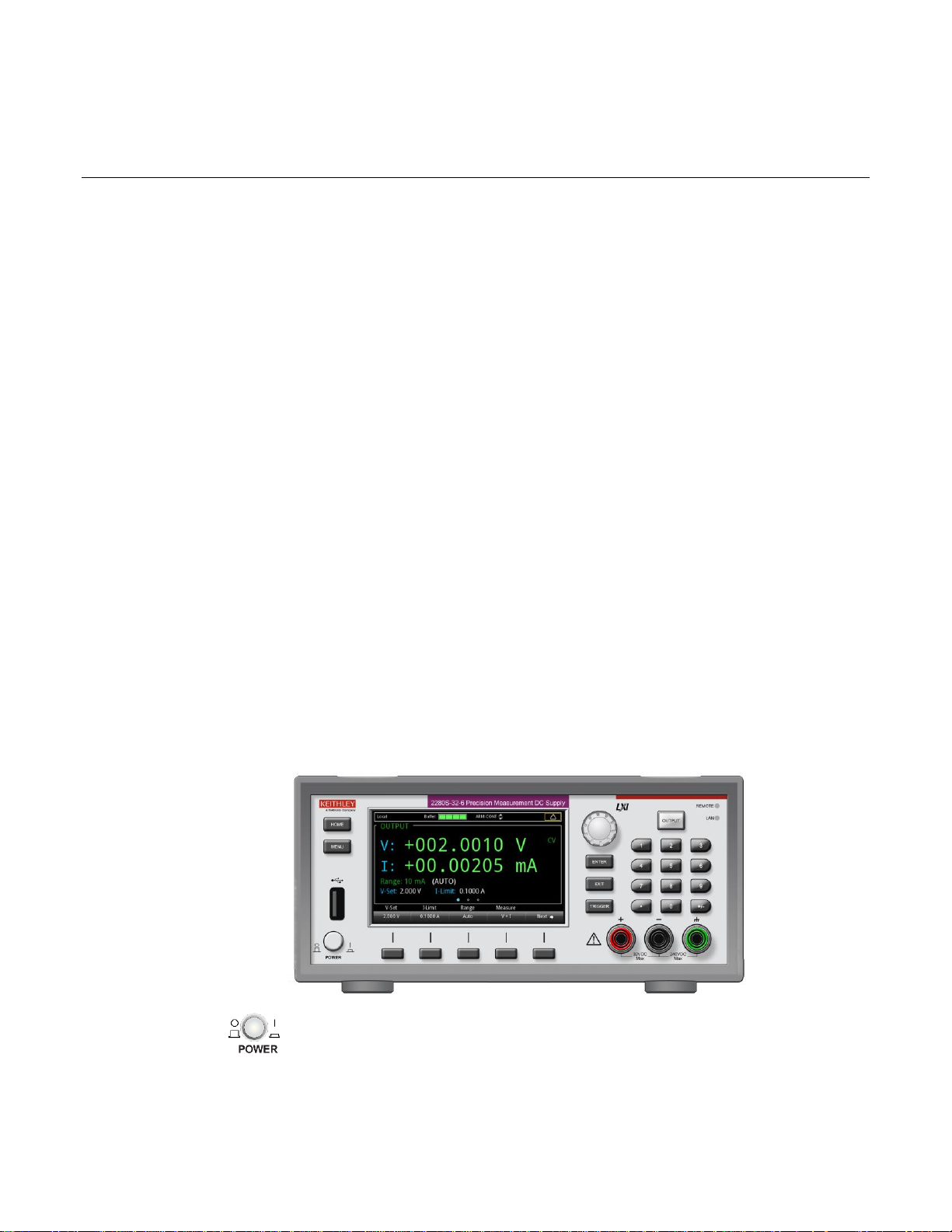
In this section:
Front-panel overview ................................................................2-1
Rear-panel overview .................................................................2-3
Front-panel user interface .........................................................2-4
Installing the system ...............................................................2-28
Test connections .....................................................................2-37
Remote communications interfaces ........................................2-44
Set voltage and current limit....................................................2-71
Select a measurement function ...............................................2-74
Select a specific measurement range .....................................2-75
Protection ................................................................................2-78
Saving setups .........................................................................2-82
Using the event log .................................................................2-85
System information .................................................................2-86
Instrument sounds ..................................................................2-87
Resets .....................................................................................2-87
POWER switch
Turns the instrument on or off. To turn the instrument on, press
the power switch so that it is in the on position (|). To turn it off,
press the power switch so that it is in the off position (O).
Section 2
General operation
Front-panel overview
The front panel of Series 2280 is shown below. Descriptions of the controls on the front panel follow
the figure.
Figure 1: Series 2280 front panel
Page 21
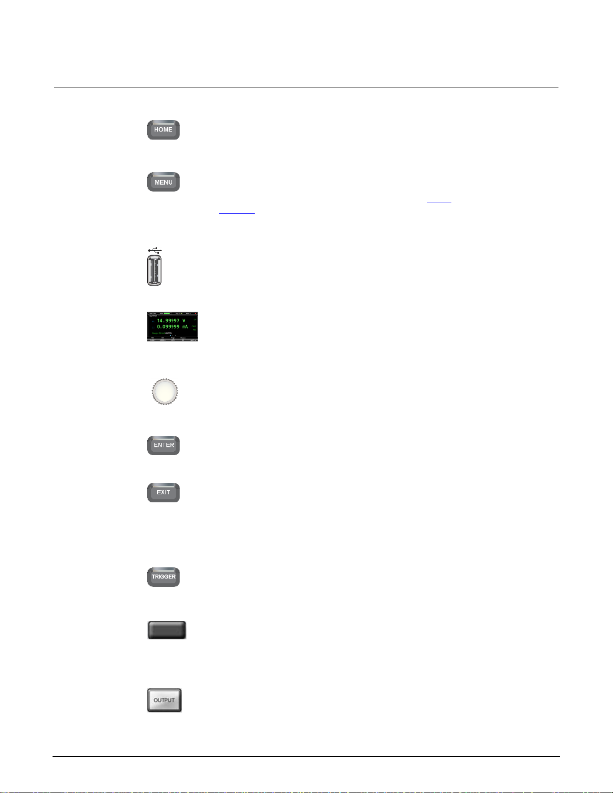
Section 2: General operation Series 2280 Precision DC Power Supply Reference Manual
2-2 077085503 / March 2019
HOME key
Returns the display to the home screen.
MENU key
Opens the main menu. Select the icons using the navigation
control and pressing the ENTER key to open source, measure,
views, trigger, and system screens. For details, see Menu
overview (on page 2-14).
USB port
Saves reading buffer data to a USB flash drive. You can also
store and retrieve scripts to and from a USB flash drive. The flash
drive must be formatted as a FAT or FAT32 drive.
LCD screen
The Series 2280 has a high-resolution, 4.3-inch color TFT LCD
display. You can access additional interactive screens by pressing
the front-panel MENU key.
Navigation control
Turning the navigation control: Moves the cursor to the left or
the right to highlight a listed value or menu item so that you can
select it.
ENTER key
Selects the highlighted choice or allows you to edit the selected
field.
EXIT key
Returns to the previous screen or closes a dialog box. For
example, press the EXIT key when the main menu is displayed to
return to the home screen. When you are viewing a subscreen
(for example, the Event Log screen), press the EXIT key to return
to the main menu screen.
TRIGGER key
Accesses trigger-related settings and operations. The action of
the TRIGGER key depends on the instrument state.
Soft keys
There are five soft keys located under the display. They provide
access to additional settings on multiple screens. For example,
press the first soft key when the main menu screen is displayed to
move the cursor to the left.
OUTPUT ON/OFF
switch
Turns the output source on or off. The switch illuminates when the
source output is on.
Page 22
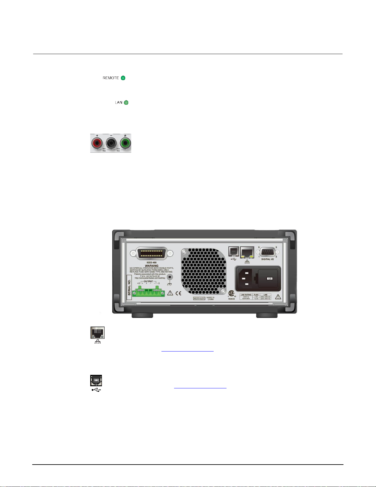
Series 2280 Precision DC Power Supply Reference Manual Section 2: General operation
077085503 / March 2019 2-3
REMOTE LED
indicator
Illuminates when the instrument is controlled through a remote
interface.
LAN LED indicator
Illuminates when the instrument is connected to a local area network
(LAN).
Front-panel
binding posts
Positive, negative, and ground output binding posts for output
connections.
LAN port
Supports full connectivity on a 10 Mbps or 100 Mbps network. The
Series 2280 is a version 1.4 Core 2011 compliant instrument that
supports TCP/IP and complies with IEEE Std 802.3 (ethernet
LAN). See LAN communications (on page 2-48).
USB port
USB-B connection for communication, control, and data transfer.
For details, see USB communications (on page 2-64).
Rear-panel overview
The rear panel of the Series 2280 is shown below; descriptions follow the figure.
Figure 2: Series 2280 rear panel
Page 23
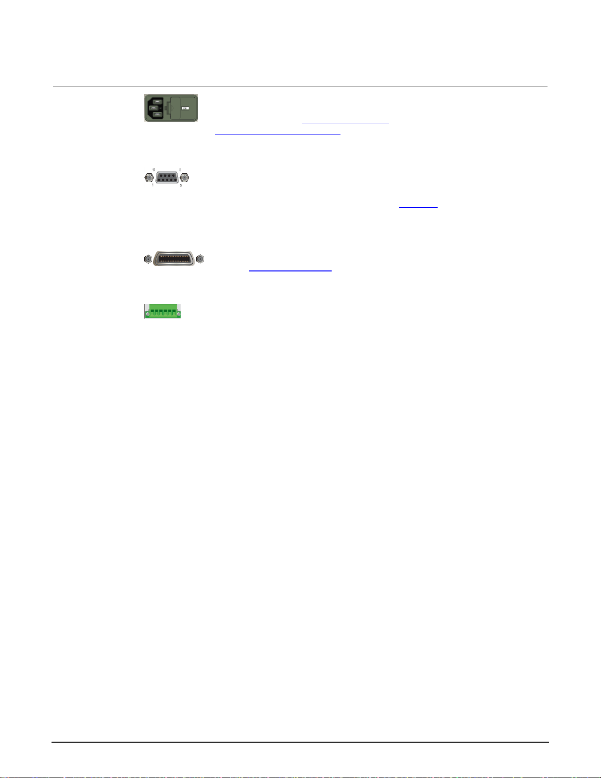
Section 2: General operation Series 2280 Precision DC Power Supply Reference Manual
2-4 077085503 / March 2019
Power module
The power module contains the AC line receptacle, the power line
fuse, and the line voltage selector switch. For safety precautions
and other details, see Line fuse replacement (on page A-1) and
Power the instrument on and off (on page 2-34).
Digital I/O port
A digital input/output port that detects and outputs digital signals.
The port provides six digital I/O lines. Each output is set high
(+5 V) or low (0 V) and can read high or low logic levels. Each
digital I/O line is an open-drain signal. Refer to Digital I/O (on
page 3-19) for information.
IEEE-488 port
GPIB connection; the default setting for the Series 2280 is 5.
Refer to GPIB communication (on page 2-45).
Rear output
terminals
Connections for the source outputs and the sense inputs.
Front-panel user interface
The front-panel user interface gives you quick access to source settings, measure settings, system
configuration, instrument status, reading buffer information, and other instrument functionality.
The following topics describe the features of the user interface in more detail.
Home screen
The default screen that you see whenever you turn the Series 2280 on is the main home screen. The
following figure shows the home screen with the different areas of the screen numbered. Descriptions
of the screen areas are in the table following the figure.
Page 24
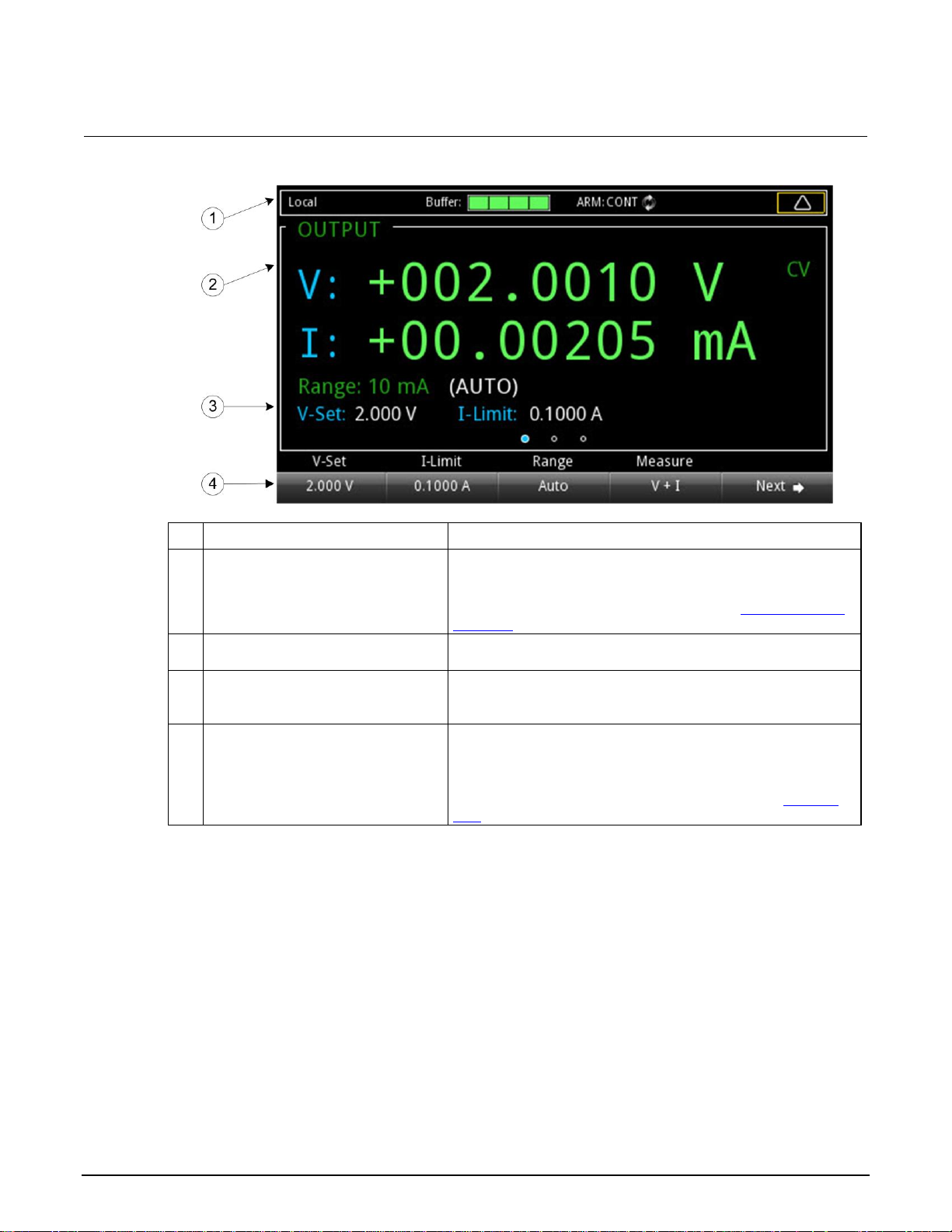
Series 2280 Precision DC Power Supply Reference Manual Section 2: General operation
077085503 / March 2019 2-5
Figure 3: Power supply home screen
#
Screen element
Description
1
System status and event indicators
Located at the top of the home screen, these indicators provide
information about the present state of the instrument. Some of
the indicators open up a dialog box with more information or a
settings menu when selected. For details, see Status and error
indicators (on page 2-5).
2
OUTPUT view area
The green part of the home screen; displays the value of the
present outputs and status indicators.
3
Setting area
Located in the lower left corner of the OUTPUT view area.
Shows the presently set measure range, voltage, and current
limit.
4
Soft-key area
The soft-key area is on the bottom of the home screen. There
are three soft-key areas that show the present setting values.
You can change these values by pressing the buttons below the
screen. To see the additional soft-key areas, select Next at the
bottom right of the screen. For more information, see Soft-key
area (on page 2-10).
Status and error indicators
The indicators across the top of the home screen contain information about the following instrument
settings and states. Highlight an indicator by turning the navigation control and then pressing ENTER
to get more information about the present state of the instrument.
Page 25
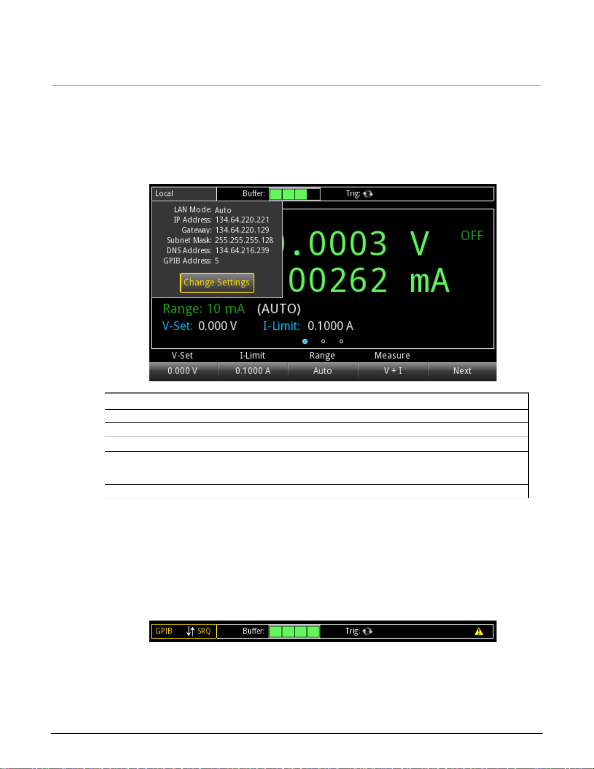
Section 2: General operation Series 2280 Precision DC Power Supply Reference Manual
2-6 077085503 / March 2019
Communication settings status indicator
Indicator
Meaning
Local
Instrument is controlled from the front panel.
GPIB
Instrument is communicating through a GPIB interface.
VXI-11
Instrument is communicating using VXI-11.
USBTMC
Instrument is communicating through a USB interface
(firmware version 1.05 and earlier, port number raw socket 5050; firmware version
1.06 and later, port number raw socket 5025).
WebPage
Instrument is communicating through a web page.
Move the focus to the communication indicator using the navigation control and press the ENTER key
to see a list of present communications settings.
Figure 4: Series 2280 communication status indicator
Instrument communication activity indicator
The activity indicator is located to the right of the communication settings status indicator. When the
instrument is communicating with a remote interface, the up and down arrows flash.
Figure 5: Instrument communication activity indicator
Page 26
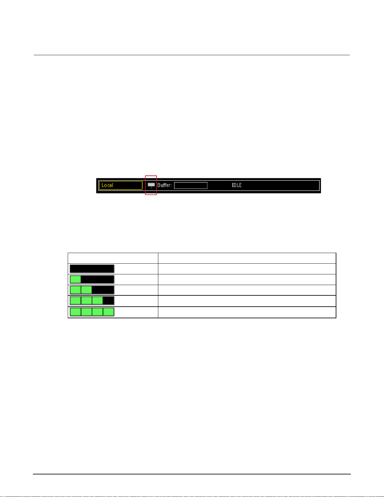
Series 2280 Precision DC Power Supply Reference Manual Section 2: General operation
077085503 / March 2019 2-7
Green bar
Buffer status
Empty
Less than one-quarter full
Less than half full, more than one-quarter full
Less than three-quarter full, more than half full
More than three-quarter full
If a service request has been generated, SRQ is displayed to the right of the up and down arrows. You
can configure the instrument to generate a service request (SRQ) when one or more errors or
conditions occur. This indicator stays on until the serial poll byte is read or all the conditions that
caused SRQ are cleared.
Level trigger enabled indicator
When a voltage level trigger or current level trigger is enabled, a solid white square indicator is visible
to the left of the Buffer indicator.
When a level trigger is enabled, data is logged to the buffer when the triggering condition is met.
Buffer indicator
The bar next to Buffer indicates how full the buffer is.
Figure 6: Level trigger enabled indicator
Page 27
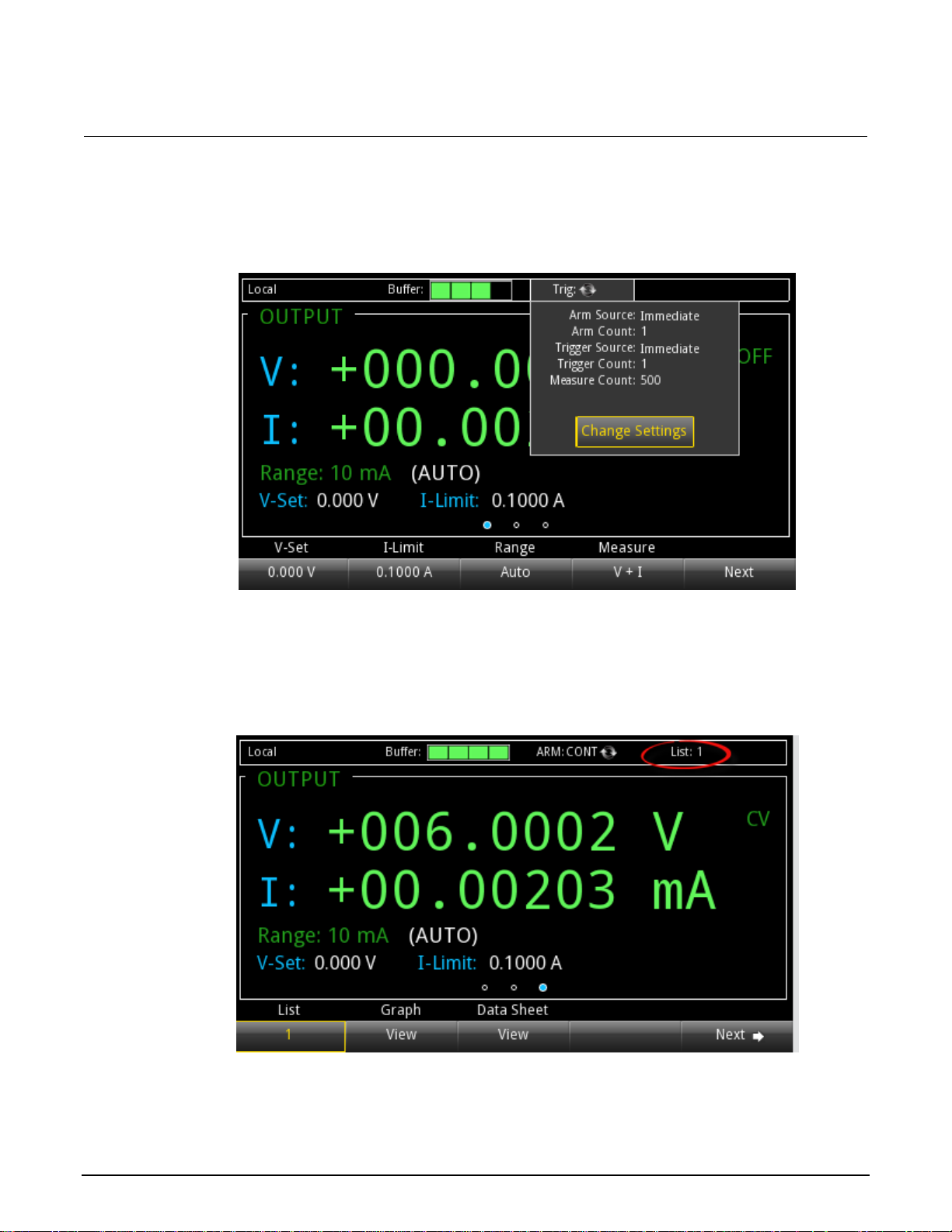
Section 2: General operation Series 2280 Precision DC Power Supply Reference Manual
2-8 077085503 / March 2019
Trigger mode settings indicator
This indicator shows the status of the trigger operation.
Figure 7: Trigger indicator
List and recall settings indicator
This indicator shows the specified list number or recall settings.
Figure 8: List and recall settings indicator
Page 28
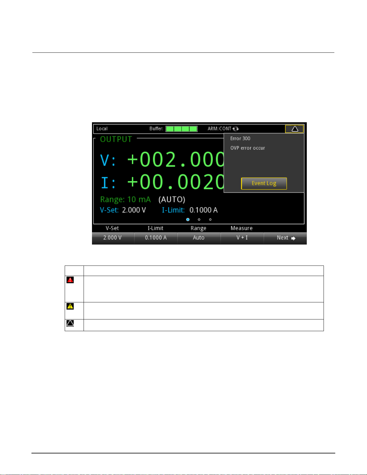
Series 2280 Precision DC Power Supply Reference Manual Section 2: General operation
077085503 / March 2019 2-9
Error and event indicator
Icon
Description
A serious error has occurred. These major errors are:
Overprotection error (overvoltage, overcurrent, or overtemperature protection).
Reverse sense leads.
A normal error has occurred. All the errors except the serious errors listed above are normal errors,
such as SCPI command errors and data overflow errors.
No new error or event messages have been logged since you last viewed the error log.
Move the focus to the error and event indicator using navigation control and press the ENTER key to
see the present error and event messages. With the focus on the Event Log button, press ENTER to
see the Error and Event Log.
Figure 9: Error and event indicator
This indicator has a different appearance based on the type of event that has been logged.
Page 29

Section 2: General operation Series 2280 Precision DC Power Supply Reference Manual
2-10 077085503 / March 2019
OUTPUT view area
Indicator
Status description
Output status
The instrument always has one of the following indicators visible:
OFF: The output is turned off.
CV: The output is turned on and the power supply is in constant voltage (CV)
mode.
CC: The output is turned on and the power supply is in constant current (CC)
mode.
DISABLE: The output is turned off and pressing the OUTPUT switch does
not turn on the output.
Fault status
The fault status indicator means that an error occurred:
OVP: Overvoltage protection.
OCP: Overcurrent protection.
OTP: Overtemperature protection.
RVS: Reversed sense leads on rear panel.
Calculation status
CALC: If either math or filter operation is enabled, the CALC indicator is displayed
in the OUTPUT view area. If none of them are enabled, the CALC indicator is
cleared.
Relative offset status
REL: If relative offset is enabled, the REL indicator is displayed.
Remote status
RWLOCK: All of the front-panel keys are disabled. The instrument can only be
controlled using a remote interface.
This area displays the values for the present measurements and instrument status indicators.
The following table lists the indicators shown on the right of the OUTPUT view area.
Page 30
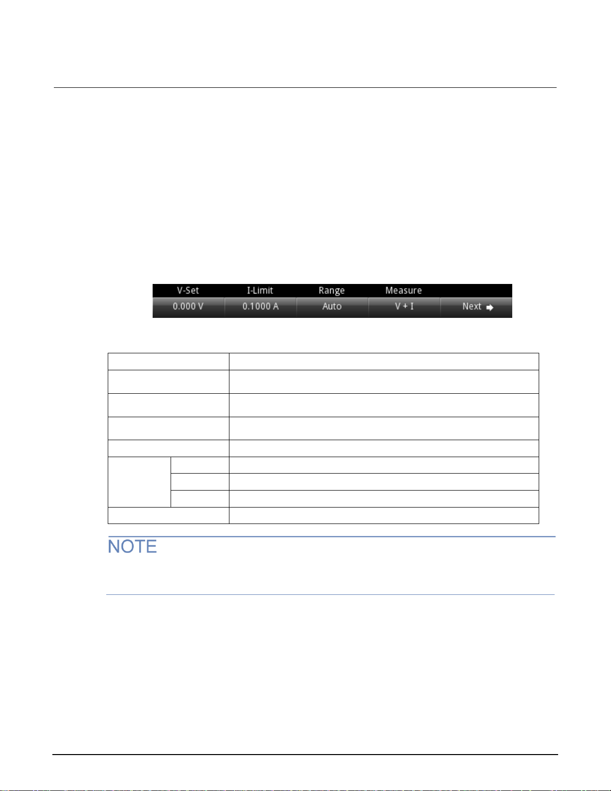
Series 2280 Precision DC Power Supply Reference Manual Section 2: General operation
077085503 / March 2019 2-11
Soft key area
Setting
Description
V-Set
Configure the voltage setting using the numerical keys, soft keys, and
navigation control.
I-Limit
Configure the current setting using the numerical keys, soft keys, and
navigation control.
Range
Press the up arrow to move up a range; press the down arrow to move
down a range. Press AUTO to set autorange.
Measure
Configure the measurement function.
V + I
Press soft key 1 to change the measurement function to concurrent.
V
Press soft key 2 to change the measurement function to voltage.
I
Press soft key 3 to change the measurement function to current.
Next
Switch to home screen 2.
The Series 2280 display has multiple soft-key areas that you can access by pressing the NEXT soft
key. The soft-key areas give you front-panel access to some instrument settings so that you can
change, enable, or disable them quickly. The following topics describe each of these screens.
Soft key area 1
Soft-key area 1 contains the settings shown in the following figure and explained in the table. To
change a setting, press the soft key to open a setting window. After configuration, close the window
by pressing the ENTER or EXIT key.
Figure 10: Soft key area 1 for power supply
If you use the navigation control to adjust the voltage and current settings, the values are applied to
the instrument immediately when output is on.
Page 31

Section 2: General operation Series 2280 Precision DC Power Supply Reference Manual
2-12 077085503 / March 2019
Setting
Description
Protect
Configure the safety settings using the numerical keys, soft keys, and
navigation control.
OVP
Edit the voltage threshold for overvoltage protection.
OCP
Edit the current threshold for overcurrent protection.
VMAX
Edit the maximum voltage setting value.
Resolution
Specify the measurement resolution for the selected measurement function.
Calculate
Specify the calculate functions including relative, math, and filter.
Rel
Enable or disable the relative function, and set the current value as the
reference value.
Math
Enable or disable the math function.
Filter
Enable or disable the filter function.
Acquire
Configure the source trigger mode.
Immediate
Set the source to immediate triggering.
External
Set the source to external triggering.
Manual
Set the source to manual triggering.
Next
Switch to home screen 3.
Soft key area 2
Soft key area 2 contains the settings shown in the following figure and explained in the table.
Figure 11: Soft key area 2 for power supply
Page 32

Series 2280 Precision DC Power Supply Reference Manual Section 2: General operation
077085503 / March 2019 2-13
Soft key area 3
Setting
Description
List
Configure the list function.
Enable
Run a specified list.
Number
Specify the list number. The default setting for list number is Demo. You can
run a predefined list. For more information about Demo, see System
Information menu (on page 2-27).
Hold Time
Set the list running time as Point or Time.
End Zero
Enable or disable setting the voltage to 0 V after the list operation has ended.
Mode
Select a list mode and specify the list cycle.
Graph
View the data plot.
Data Sheet
View the data sheet.
Buffer
Clear the data buffer.
Next
Switch to home screen 1.
Soft key area 3 contains the settings shown in the following figure and explained in the table. To
change a setting, press the soft key to open a settings window. After configuration, close the window
by pressing the ENTER or EXIT key.
Figure 12: Soft key area 3
Page 33

Section 2: General operation Series 2280 Precision DC Power Supply Reference Manual
2-14 077085503 / March 2019
Menu overview
To access the main menu, press the MENU key on the Series 2280 front panel. The organization of
the main menu is shown in the figure below.
Figure 13: Power supply main menu
The main menu is organized into five submenus, which are labeled in green across the top of the
display. The icons in each column open interactive screens.
Source menu
The menus organized under Source in the main menu allow you to select, configure, and perform
source and list operations from the Series 2280 front panel. The following topics describe the settings
that are available on these interactive screens.
Page 34

Series 2280 Precision DC Power Supply Reference Manual Section 2: General operation
077085503 / March 2019 2-15
Source Settings menu
Setting
Description
V-Set
Configure the voltage setting using the numerical keys, soft keys, and
navigation control.
I-Limit
Configure the current setting using the numerical keys, soft keys, and
navigation control.
Output
Turn the output on or off. You can also disable the output. Once output is
disabled, the output is off and the OUTPUT switch is ignored.
Output Delay
Enable or disable output delay.
Slew Rise
Set the rising rate for voltage source.
Slew Fall
Set the falling rate for voltage source.
Delay Rise
Set the delay time that the instrument waits before turning on the output.
Delay Fall
Set the delay time that the instrument waits before turning off the output.
Setting
Description
Overvoltage Protection
Set the overvoltage protection limit of the source output to restrict the
maximum voltage level that the instrument can source.
Overcurrent Protection
Set the overcurrent protection limit of the source output to restrict the
maximum current level that the instrument can source.
Maximum Voltage
Set the maximum voltage that can be set. This influences the voltage setting
range.
You can change the following settings by pressing the MENU key, moving focus to the Source
Settings icon, and pressing the Enter key.
Source Protect menu
This menu allows you to configure the protection settings.
Page 35

Section 2: General operation Series 2280 Precision DC Power Supply Reference Manual
2-16 077085503 / March 2019
Source List menu
Setting
Description
List
Select a list from nonvolatile memory; import a list from an external USB flash
drive; save a list to an external USB flash drive.
Save
Save the present list to nonvolatile memory.
Delete
Delete the specified points from the list.
Insert
Insert one point with default settings before each specified point. The default
settings are: 0.000 V, 0.1000 A, 0.100 s.
Copy
Copy the selected settings of the point and insert a new point with the same
settings before each point.
Points
Displays the number of points in the list (read only).
List table
This table shows all the setting values in the list. You can edit them by
moving focus and pressing the ENTER key.
Setting
Description
Source Delay
Configure the delay time using the numerical keys, navigation wheel, and
soft keys.
State
Enable or disable the delay that occurs when the source is turned on.
This menu allows you to set up a source configuration list.
Source Delay menu
This menu allows you to set a delay for the source. For details, refer to Source delay (on page 3-7).
Page 36

Series 2280 Precision DC Power Supply Reference Manual Section 2: General operation
077085503 / March 2019 2-17
Measure menu
Setting
Description
Function
Select which type of measurement is active:
V + I: Concurrent measurement function. The instrument measures
voltage and current at the same time.
V: Voltage measurement function. The instrument only measures
voltage.
I: Current measurement function. The instrument only measures
current.
Range
Set the measurement range for the selected measurement function or select
Auto to have the instrument select the range automatically.
Digits
Select the display digits: 6½, 5½, or 4½ digits.
Auto Zero
Set Auto Zero to On so that the instrument periodically gets new
measurements of its internal ground and voltage reference. This setting
increases measurement accuracy, but may slow measurement time.
NPLC
Set the amount of time that the input signal is measured. A lower number of
power line cycles (NPLCs) results in faster reading rates, but increased
noise. A higher number of NPLCs results in lower reading noise, but slower
reading rates.
Power Line Freq
Read only; shows the present power line frequency setting.
The menus organized under Measure in the main menu allow you to select, configure, and perform
measure operations from the Series 2280 front panel. The following topics describe the settings that
are available on these interactive screens.
Measure Settings menu
This menu contains settings for the presently selected measurement function, which is identified by
the Type indicator in the upper right corner of the menu. The line frequency is also shown here.
Page 37

Section 2: General operation Series 2280 Precision DC Power Supply Reference Manual
2-18 077085503 / March 2019
Measure Rel/Filter menu
Setting
Description
Function
Displays the presently selected function.
Rel State
Use the relative offset feature to subtract a set value or a baseline reading
from measurement readings. When you enable relative offset, all subsequent
measurements are displayed as the difference between the actual measured
value and the relative offset value.
Rel Acquire
Acquire the present reading as a relative value.
Reference
Configure the offset value. You can use Rel Acquire to set the present
reading as the relative offset value. You can also specify the relative offset
using the numerical keys, navigation control, and soft keys. The default value
is 0.
Type
The Series 2280 only supports moving average filtering. This filter
continuously adds measurements to the stack on a first-in, first-out basis,
replacing the oldest measurement in the stack with a new measurement.
Filter State
Enable or disable filtering of measurements.
Count
Sets the number of measurements that are averaged when filtering is
enabled. The number of measurements can be 2 through 100.
Window
Filtering uses a window to control filter threshold. When the input signal
remains within the selected window, measurements continue to be placed in
the stack. If the input signal changes to a value outside the window, the filter
resets and starts processing again, starting with new measurements.
Setting
Description
Type
When the Math State is set to On, the mx+b math operation is performed on
measurements.
mx+b: Manipulate normal display readings by adjusting the m and b factors.
State
When the state is set to On, any math operations specified for the present
measurement function are performed before completing the measurement.
m(Gain)
Specify the scale factor for mx+b math operation. The valid range is –1e6 to
+1e6.
b(Offset)
Specify the offset for mx+b math operation. The valid range is –1e6 to +1e6.
Function
Displays the presently selected function.
Units
Specify the units suffix name for mx+b operation. You can only select one
capital letter for the name from the front panel.
Buffer Data Type
Select Reading to store measurements to the buffer without performing math
operations on them.
Select CALC to store measurements to the buffer after performing specified
math operations.
This menu contains settings that specify the way measurement information is returned.
Measure Math menu
This menu contains settings that configure the math function.
Page 38

Series 2280 Precision DC Power Supply Reference Manual Section 2: General operation
077085503 / March 2019 2-19
Measure Data Buffers menu
Setting
Description
Size
Set the maximum number of readings the buffer can store (2 to 2,500). Note
that when you resize a buffer, the readings contained in that buffer are
cleared.
Mode
Select Always to have the buffer fill continuously, overwriting old data when
the buffer is filled.
Select Next to have the buffer stop collecting data when it is filled (no data is
overwritten).
Select Never to have the buffer stop collecting data.
Statistics
Select statistics to apply to the readings in the buffer. Available statistics:
Minimum: Minimum value
Maximum: Maximum value
Peak-Peak: Maximum value - minimum value
Mean: Average
Std Dev: Standard deviation
Statistics Function
Select whether to apply statistics calculations to current or voltage readings.
You can only specify one of them at a time.
Auto Clear
Enable or disable autoclear for the buffer. When autoclear is enabled, the
buffer will automatically clear when the storage process starts.
Statistics Format
Select the data elements to be shown on the graph and data sheet screen.
Available data elements:
Value: Voltage and current reading
Time: The timestamp for the data point
Number: Reading number
All: Voltage and current reading, timestamp for the data point, and
reading number
Export To USB
Save the buffer to a .csv file, which can be opened by a spreadsheet
program.
Clear Buffer
Clear all the data in the buffer.
From this screen you can save, resize, and clear buffers. You also can set buffer fill mode and
statistics functions.
Page 39

Section 2: General operation Series 2280 Precision DC Power Supply Reference Manual
2-20 077085503 / March 2019
Views menu
Setting
Description
Graph
View the readings in a graphical representation.
Statistics
Turn the statistics function on or off. You can view statistics results on the
graph screen when this function is on.
Window
Fine-tune the output on the graph view screen.
Position
Set the center point of the graph for buffer data. For example, if the buffer
size is 100, a position of 30% means the 30th reading in the buffer is at the
middle point in the plot.
Zoom
Specify the number of readings that are displayed on the screen.
Y-Axis
Select the data that is plotted on the Y-axis. You can select Current,
Voltage, or Both.
I Auto Adjust
Enable or disable the automatic adjustment of the current scale and offset of
the Y-axis. When automatic adjustment is disabled, you can adjust the scale
and offset manually.
V Auto Adjust
Enable or disable the automatic adjustment of the voltage scale and offset of
the Y-axis. When automatic adjustment is disabled, you can adjust the scale
and offset manually.
I Manual Adjust
Manually adjust the current scale and offset of the Y-axis.
Scale is the volts/division, or amps/division. A plot has 7 divisions.
Offset is the value of the lowest division displayed.
V Manual Adjust
Manually adjust the voltage scale and offset of the Y-axis.
Scale is the volts/division, or amps/division. A plot has 7 divisions.
Offset is the value of the lowest division displayed.
Setting
Description
Data Sheet
Show the data in the reading buffer.
Statistics
Turn on or off the statistics function. You can view statistics results in the
data sheet when this function is on.
The menus organized under View in the main menu allow you to view the data plot, sheet, and
statistics results on the Series 2280 front panel. The following topics describe the settings that are
available on these interactive screens.
Views Graph menu
Selecting the Graph menu opens a screen that allows you set up and see the measurements in a
graphical format.
Views Sheet menu
This menu allows you to view data in the selected reading buffer.
Page 40

Series 2280 Precision DC Power Supply Reference Manual Section 2: General operation
077085503 / March 2019 2-21
Trigger menu
Setting
Description
List type
Displays the list type when the list function is enabled. The Series 2280
supports the following types of lists:
Step: One trigger signal will output one list step.
Sweep: One trigger signal will output the entire list.
Disable: The list is disabled.
Idle
Cont:On: Continuous trigger is on.
Cont:Off: Continuous trigger is off and no readings are taken.
Arm Source
Select the control source for the arm layer.
Arm Count
Set the number of times to repeat the arm event.
Trigger Source
Select the control source for the trigger layer.
Trigger Count
Set the number of times to repeat the trigger event.
Reset Configuration
Reset the trigger settings to factory default, including trigger source and
trigger count.
Sample Count
Set the number of measurements to be performed when a measurement is
requested.
This menu allows you to configure triggering operations from the Series 2280 front panel. The
following topics describe the settings that are available on these interactive screens.
Trigger Configure menu
This menu allows you to configure the triggering operations. The Series 2280 has two trigger layers:
Arm layer and trigger layer.
Page 41

Section 2: General operation Series 2280 Precision DC Power Supply Reference Manual
2-22 077085503 / March 2019
Trigger Digital In/Out menu
Setting
Description
Line 1
Specify one of the following line modes for digital I/O line 1:
Trigger In
Output HI
Output LO
Manual In
Line 2
Specify one of the following line modes for digital I/O line 2:
Meter Out
Output HI
Output LO
Manual In
Line 3
Specify one of the following line modes for digital I/O line 3:
Fault Out
Output HI
Output LO
Manual In
Line 4
Specify one of the following line modes for digital I/O line 4 to line 6:
Output HI
Output LO
Manual In
Line 5
Line 6
This menu allows you to configure the mode for each digital I/O line. The Series 2280 has 6 digital I/O
lines (line 1 to line 6). For details, refer to Digital I/O (on page 3-19).
Page 42

Series 2280 Precision DC Power Supply Reference Manual Section 2: General operation
077085503 / March 2019 2-23
Level Trigger menu
Setting
Description
Voltage
If you set this as On, the triggering point is based on the value of voltage.
If you set this as Off, the triggering point is not based on the value of voltage.
Current
If you set this as On, the triggering point is based on the value of current.
If you set this as Off, the triggering point is not based on the value of current.
Voltage Level
Set the value of the voltage that will trigger the data logging in the data buffer.
Current Level
Set the value of the current that will trigger the data logging in the data buffer.
Voltage
Direction
If you set this as Rise, the trigger will be activated when the voltage rises above the
triggering point.
If you set this as Fall, the trigger will be activated when the voltage falls below the
triggering point.
Current
Direction
If you set this as Rise, the trigger will be activated when the current rises above the
triggering point.
If you set this as Fall, the trigger will be activated when the current falls below the
triggering point.
Offset
Set how many points will be saved before the trigger is activated.
This menu allows you to configure a triggering condition to start to log the data in the data buffer
during the test. You can set the triggering point based on the voltage or current. The triggering
condition is based on whether the current or voltage rises or falls.
When the level trigger function is enabled, it clears all the data in the buffer and the buffer mode is
set to Always.
When the level trigger is activated, it clears the data in the buffer (except the points set by the Offset
parameter) and the buffer mode is set to Next.
When the level trigger is enabled, a solid white rectangle is visible at the top of the display screen, as
shown in the following figure.
Figure 14: Level trigger enabled indicator
Page 43

Section 2: General operation Series 2280 Precision DC Power Supply Reference Manual
2-24 077085503 / March 2019
Setting
Description
Save
Save the present instrument settings as a user-saved setup. The Series 2280
supports up to five setups.
Recall
Return the instrument to the specified setup.
Auto Load Setup 1
If you choose On, the instrument will load setup1 after it is powered
on.
If you choose Off, the instrument will not load setup1 after it is
powered on.
You can use the following SCPI commands to configure the level trigger:
:TRACe[n]:TRIGger:VOLTage:STATe
:TRACe[n]:TRIGger:VOLTage[:LEVel]
:TRACe[n]:TRIGger:VOLTage:DIRection
:TRACe[n]:TRIGger:CURRent:STATe
:TRACe[n]:TRIGger:CURRent[:LEVel]
:TRACe[n]:TRIGger:CURRent:DIRection
:TRACe[n]:TRIGger:OFFSet
In addition, you can query whether any level trigger has been activated using the following SCPI
command:
:TRACe[n]:TRIGger:OCCUR?
System menu
The menus under System in the main menu allow you to configure general instrument settings from
the Series 2280 front panel. Among these settings are the event log, communications, error beeper,
key clicks, backlight brightness and timer, time and date, calibration, and system and calibration
passwords and settings.
The following topics describe the settings that are available on these interactive screens.
System Save/Recall menu
This menu allows you to save the present settings and any source or measure configuration lists to
internal memory or an external USB flash drive. You can also run a setup from internal memory or a
USB flash drive.
Page 44

Series 2280 Precision DC Power Supply Reference Manual Section 2: General operation
077085503 / March 2019 2-25
System Settings menu
GPIB settings
Description
Address
The default GPIB address is 5. You can set the address to any address from 1 to
30, if it is unique in the system. This address cannot conflict with an address that is
assigned to another instrument or to the GPIB controller.
LXI LCI
Reset the LAN configuration
LAN settings*
Description
TCP/IP Mode
Select Manual to manually set the Local IP, gateway, and subnet mask values.
Select Auto to set the instrument to automatically obtain an IP address.
Gateway
When TCP/IP Mode is set to Manual, you can see the present gateway address.
To change the address, select the button next to Gateway and enter a new
address.
IP Address
When TCP/IP Mode is set to Manual, you can see the present local IP address. To
change the address, select the button next to Local IP and enter a new address.
Subnet
When TCP/IP Mode is set to Manual, you can see the present subnet mask
address. To change the address, select the button next to Subnet and enter a new
address.
MAC Address
Read-only text that shows the present MAC address of the instrument.
Apply Settings
To save any changes you made on the LAN tab, select Apply Settings.
* You must select Apply Settings after changing any of the settings on this tab to save your settings.
This menu contains general instrument settings.
Communication settings
This menu allows you to configure GPIB, LAN, and USB communications settings.
To access the System Communication settings screen:
1. Move focus to the communication indicator at the top left of the home screen and press the
ENTER key. A dialog box opens that shows current communication settings.
2. Select Change Settings. The System Communication screen is displayed.
3. Select an interface by moving focus to the Interface button and pressing the ENTER key.
You can also access this menu through the main menu by selecting Settings (under System) >
Communications.
There are no settings for the USB interface.
The Series 2280 powers up using the last remote interface used.
Page 45

Section 2: General operation Series 2280 Precision DC Power Supply Reference Manual
2-26 077085503 / March 2019
Setting
Description
Key Click
Turn the instrument key-click sound on or off from this menu.
Backlight Timer
You can set the front-panel display to dim after a period of time, or
you can set it so that it will never dim.
Backlight Brightness
You can adjust the brightness of the front-panel display. Selecting
this setting opens a sliding adjustment scale that adjusts the
brightness as a percent of total brightness.
Time and Date
Set the instrument month, day, year, and time from this menu.
Error Beeper
Turn the error beeper on or off.
System Password
Change the remote connection or calibration passwords. You need
the remote connection password to open the LXI virtual front panel
and send SCPI commands. You need the calibration password
before you can calibrate the Series 2280.
Reset
System Reset
Selecting this option resets many of the instrument commands to
their default values. For more information about what commands get
reset, see Reset default values (on page 2-88).
Password Reset
Selecting this option reverts the passwords to their default values.
Settings
Description
Export to USB
Saves the event log to a .csv file on the USB flash drive. The file name is
eventlog.csv.
Clear Event Log
Clears all entries from the event log.
Other system settings
System Event Log menu
The System Event Log menu allows you to view, save, and clear the event log. The event log entries
are error messages, which may indicate that a command was sent incorrectly.
Page 46

Series 2280 Precision DC Power Supply Reference Manual Section 2: General operation
077085503 / March 2019 2-27
System Information menu
Setting
Description
Demo
When you select Demo mode, you can choose List Mode or Pulse.
Upgrade
Selecting this option initiates a firmware upgrade from a file on a USB flash
drive (the flash drive must be less than or equal to 2 GB and formatted in
the FAT file format). For details, see Upgrading the firmware (on page A-2).
New
Update the firmware to the latest version. During the upgrade process, the
instrument verifies that the version you are loading is newer than what is on
the instrument. If the version is older or at the same revision level, no
changes are made.
Previous
Selecting this option returns the Series 2280 to a previous version of the
firmware from a file on a USB flash drive. When you return to a previous
version, the instrument verifies that the version you are loading is earlier
than what is on the instrument.
If there are several versions on the USB flash drive that are older than what
is on the instrument, the newest one is selected.
Calibrate
Start to calibrate the instrument.
The System Information menu shows the serial number, firmware version, and the calibration adjust
date and count. It also allows you to upgrade the firmware and calibrate the instrument.
Adjusting the backlight brightness and timer
You can adjust the brightness of the Series 2280 display from the front panel or over a remote
interface. You can also set the backlight to dim after a specified period of time has passed with no
front-panel activity (available for the front-panel display only). The backlight settings are not affected
by reset.
Screen life is affected by how long the screen is on at full brightness. The higher the brightness
setting and the longer the screen is bright, the shorter the screen life.
To adjust the backlight brightness from the front panel:
1. Press the MENU key.
2. Under System, select Settings.
3. Highlight the button next to Backlight Brightness and press ENTER. The Backlight Brightness
dialog box opens.
4. Enter a value and press ENTER.
Page 47

Section 2: General operation Series 2280 Precision DC Power Supply Reference Manual
2-28 077085503 / March 2019
To set the backlight timer from the front panel:
1. Press the MENU key.
2. Under System, select Settings.
3. Select the button next to Backlight Timer and press ENTER. The Backlight Timer dialog box
opens.
4. Select a timer setting and press ENTER.
To adjust the brightness using the SCPI remote interface:
Send the following command:
:DISPlay:BRIGhtness <brightness>
Where <brightness> is from 1 to 100. For example, 75 represents 75 percent brightness and 100
represents full brightness.
Installing the system
This section contains information on how to install your Series 2280 power supply.
Bumpers
The Series 2280 has front and rear bumpers for using the instrument on a benchtop.
Removing bumpers
You can remove the bumpers on the Series 2280 if you want to mount the instrument in a rack.
If you remove the bumpers, be sure to store them for future benchtop use.
To remove the bumpers:
1. Grasp the front bumper on each side of the Series 2280 and gently pull it toward you until the
bumper comes off of the instrument.
Page 48

Series 2280 Precision DC Power Supply Reference Manual Section 2: General operation
077085503 / March 2019 2-29
Remove all connections to the rear panel of the Series 2280 before removing the rear bumper.
2. To remove the rear bumper, repeat the procedure in step 1.
Dimensions
Figure 15: Removing the front bumper
The following figures show the mounting screw locations and the dimensions of the instrument with
and without the bumpers.
The instrument weighs 10.67 kg (23.53 lb) with the bumpers and 10.40 kg (22.95 lb) without them.
The following figure shows the mounting screw locations and dimensions. Mounting screws must be
#6-32 with a maximum screw length of 11.13 mm (0.438 in.). The dimensions shown are typical for
both sides of the instrument.
Figure 16: Series 2280 mounting screw locations and dimensions
Page 49

Section 2: General operation Series 2280 Precision DC Power Supply Reference Manual
2-30 077085503 / March 2019
The following figures show the dimensions when the bumpers are installed.
Figure 17: Series 2280 front and rear panel dimensions with bumpers
Page 50

Series 2280 Precision DC Power Supply Reference Manual Section 2: General operation
077085503 / March 2019 2-31
Figure 18: Series 2280 top and side dimensions with bumpers
Page 51

Section 2: General operation Series 2280 Precision DC Power Supply Reference Manual
2-32 077085503 / March 2019
The following figures show the dimensions when the bumpers have been removed.
Figure 19: Series 2280 front and rear panel dimensions with bumpers removed
Page 52

Series 2280 Precision DC Power Supply Reference Manual Section 2: General operation
077085503 / March 2019 2-33
Figure 20: Series 2280 top and side dimensions with bumpers removed
Page 53

Section 2: General operation Series 2280 Precision DC Power Supply Reference Manual
2-34 077085503 / March 2019
Power the instrument on and off
Follow the procedure below to connect the Series 2280 to line power and turn on the instrument. The
Series 2280 operates on the following ranges: 100 V, 120 V, 220 V, or 240 V at a frequency of 50 Hz
or 60 Hz. You need to select the line voltage and frequency on the rear panel. Make sure the line
voltage setting is compatible with the line voltage in your area.
The Series 2280 must be turned on and allowed to warm up for at least one hour to achieve rated
accuracies.
The power cord supplied with the Series 2280 contains a separate protective earth (safety
ground) wire for use with grounded outlets. When proper connections are made, the
instrument chassis is connected to power-line ground through the ground wire in the power
cord. In addition, a redundant protective earth connection is provided through a screw on the
rear panel. This terminal should be connected to a known protective earth. In the event of a
failure, not using a properly grounded protective earth and grounded outlet may result in
personal injury or death due to electric shock.
Do not replace detachable mains supply cords with inadequately rated cords. Failure to use
properly rated cords may result in personal injury or death due to electric shock.
Operating the instrument on an incorrect line voltage may cause damage to the instrument,
possibly voiding the warranty.
Figure 21: Series 2280 rear panel
Page 54

Series 2280 Precision DC Power Supply Reference Manual Section 2: General operation
077085503 / March 2019 2-35
To connect the power cord:
1. Make sure that the front panel POWER switch is in the off (O) position.
2. Properly set the 100 V/120 V or 220 V/240 V selector switch located on the rear panel.
3. Connect the female end of the supplied power cord to the AC receptacle on the rear panel.
4. Connect the other end of the power cord to a grounded AC outlet.
To turn a Series 2280 on and off:
On some sensitive or easily damaged devices under test (DUTs), the instrument power-up
sequence can apply transient signals to the DUT that may affect or damage it. When testing
this type of DUT, do not make final connections to it until the instrument has completed its
power-up sequence and is in a known operating state.
1. Disconnect any devices under test (DUTs) from the Series 2280 before turning the instrument on.
2. To turn your instrument on, press the front-panel POWER switch to place it in the on (I) position.
A status bar is displayed as the instrument powers up. The home screen is displayed when power
up is complete.
3. To turn your instrument off, press the front-panel POWER switch to place it in the off (O) position.
On some sensitive or easily damaged devices under test (DUTs), the instrument power-down
sequence can apply transient signals to the DUT that may affect or damage it. When testing
this type of DUT, disconnect it from the instrument before turning the instrument off.
Turning the Series 2280 output on
You can turn the Series 2280 output on from the front panel or by sending remote commands.
To turn the output on using the front panel:
Press the OUTPUT switch. The instrument is in the output-on state when the switch is illuminated.
The instrument is in the output-off state when the switch is not illuminated.
For the power supply function only, you can also turn on the output from the Source Setting screen.
Select the button next to Output and press the State soft key. The output state screen is displayed.
You can enable the output by pressing the On soft key.
Page 55

Section 2: General operation Series 2280 Precision DC Power Supply Reference Manual
2-36 077085503 / March 2019
To turn the output on using a SCPI command:
:OUTPut:STATe ON
When you are using a remote interface to control the instrument and the output is turned off,
pressing the OUTPUT switch cannot turn the output on. However, if the output is turned on, you can
press the OUTPUT switch to turn the output off.
Turning the Series 2280 output off
Turning the Series 2280 output off does not place the instrument in a safe state.
Hazardous voltages may be present on all output and guard terminals. To prevent electrical
shock that could cause injury or death, never make or break connections to the Series 2280
while the instrument is powered on. Turn off the equipment from the front panel or
disconnect the main power cord from the rear of the Series 2280 before handling cables.
Putting the equipment into an output-off state does not guarantee that the outputs are
powered off if a hardware or software fault occurs.
Using the front panel:
Press the OUTPUT switch. The instrument is in the output-on state when the switch is illuminated.
The instrument is in the output-off state when the switch is not illuminated.
You can also turn off the output from the Source Setting screen. Select the button next to Output
and press the State soft key. The output state screen is displayed. You can turn off the output by
pressing the Off soft key.
Using SCPI commands:
To turn the output off, send the command:
:OUTPut[:STATe] OFF
Page 56

Series 2280 Precision DC Power Supply Reference Manual Section 2: General operation
077085503 / March 2019 2-37
Disable the Series 2280 output
You can disable the Series 2280 output from the front panel and by sending remote commands. If
disabled, pressing the OUTPUT switch on the front panel does not turn on the output.
Using the front panel:
1. From the home screen, press MENU.
2. Under Source, select Settings.
3. Select the button next to Output and press ENTER. The Output window is displayed.
4. Select Status. The Status window is displayed.
5. Select the box below Disable.
Using a SCPI command:
To disable the output, send the command:
:OUTPut[:STATe] DISable
Test connections
You can use either the front-panel or rear-panel terminals to make connections to the device under
test (DUT). You must use either the front or rear terminals. You cannot use connections to both the
front panel and rear panel for the same test setup; you must choose one or the other.
Hazardous voltages may be present on all output and guard terminals. To prevent electrical
shock that could cause injury or death, never make or break connections to the Series 2280
while output is on.
To prevent electric shock, test connections must be configured such that the user cannot
come in contact with conductors or any device under test (DUT) that is in contact with the
conductors. It is good practice to disconnect DUTs from the instrument before powering the
instrument. Safe installation requires proper shields, barriers, and grounding to prevent
contact with conductors.
The basic connection configurations for the Series 2280 include:
Two-wire sense connection
Four-wire remote sense connection
Page 57

Section 2: General operation Series 2280 Precision DC Power Supply Reference Manual
2-38 077085503 / March 2019
Front-panel connector
Front-panel connectors are available to connect load wires for bench operation. A chassis ground
binding post is also provided on the front panel.
There are two locations on the binding post to connect the wire. See the picture above. You can use
one of the methods below to connect the outputs from the front panel:
Insert standard banana plugs into the front connectors as shown in location 1.
Insert safety test leads into the front connectors as shown in location 1. For details, see the
following figure.
Figure 22: Front-panel binding post
Insert the wires into the hole as shown in location 2, and fasten the wires by hand-tightening the
binding posts. The wire size should be from American wire gage (AWG) 20 to AWG 12.
Figure 23: Safety test lead connection
The wire must be heavy enough not to overheat while carrying the short-circuit output
current of the unit. You must meet the wiring requirements described above. Make sure the
wire you use is enclosed inside a safety cover.
Page 58

Series 2280 Precision DC Power Supply Reference Manual Section 2: General operation
077085503 / March 2019 2-39
Rear-panel output mating connector
Available connections on the rear output mating connector include the output high (+), output low (-),
sense high (+), and sense low (-) terminals. The rear output terminals accept wire sizes from AWG 20
to AWG 12.
Two-wire local sense connection
You can connect a device to the instrument in a two-wire sense connection as shown in the following
figure.
Figure 24: Two-wire connection
If you use a two-wire sense connection, you can use the offset function of Series 2280 to cancel out
the wire resistance. For details, refer to Relative offset (on page 4-12).
Page 59

Section 2: General operation Series 2280 Precision DC Power Supply Reference Manual
2-40 077085503 / March 2019
Four-wire sense connection
Using four-wire remote sensing connections ensures that the programmed voltage is applied to the
load and compensates for the voltage drop in the leads between the power supply and the load. The
maximum voltage drop is 1 V per lead.
As shipped, the sense terminals are connected to the output terminals by shorting jumpers. Before
connecting the wire, make sure the shorting jumpers have been removed. When you connect the
power supply for remote sensing, the overvoltage protection (OVP) circuit senses the voltage at the
sensing points (load) and not the output terminals.
Figure 25: Four-wire (remote sensing) DUT connection to rear panel
Page 60

Series 2280 Precision DC Power Supply Reference Manual Section 2: General operation
077085503 / March 2019 2-41
To reduce the environmental noise, load wires and sense wires must be twisted. For more
information, refer to the following figure.
Figure 26: Four-wire connection with twisted-pair wires
Make sure you make the connections correctly. Incorrect connections between output and
sense terminals will result in a serious error and may damage the device under test (DUT).
For more information, see Open leads detection (on page 2-42) and Reverse sense leads (on
page 2-43).
Page 61

Section 2: General operation Series 2280 Precision DC Power Supply Reference Manual
2-42 077085503 / March 2019
Open leads detection
When using four-wire sense connections, a missing or faulty connection with Sense HI, Sense LO,
Output HI, or Output LO results in improperly regulated voltage and inaccurate voltage
measurements. The voltage readback shown on the front panel is not equal to the real output voltage.
The open leads clamp circuit can limit the output voltage between Output HI and Output LO to less
than V
V
total
total
= V
set
.
+ V
clamp
Where V
V
clamp
is the voltage setting.
set
is introduced from a clamp circuit, typically less than 7 V. Without the clamp circuit, the
instrument could output its maximum voltage when the open lead occurs.
Example
1. Connect a 300 Ω resistor to the rear-panel mating connector. For details, refer to Four-wire sense
connections (on page 2-40).
2. Set the voltage to 3 V and current limit to 1 A.
3. Turn on the output.
The following figure shows the voltage readback and output voltage when you make a correct
four-wire sense connection.
Figure 27: Correct four-wire connections
4. Power off the instrument and remove one of the test leads.
To avoid damage to the device under test (DUT), you must power off the instrument before
making any changes on the connections. Otherwise, it may damage the device under test
(DUT).
Page 62

Series 2280 Precision DC Power Supply Reference Manual Section 2: General operation
077085503 / March 2019 2-43
5. Power on the instrument and repeat steps 1 through 3.
The following figure shows the error that is displayed on the front panel.
Figure 28: Open lead error
You can retrieve the error number and message through a remote interface by sending
the :SYSTem:ERRor? command.
Reversed sense leads
When the following connections occur, the instrument generates a reversed sense leads error.
Sense HI is connected to Output LO
Sense HI is connected to Sense LO
Sense LO is connected to Output HI
When a reverse sense leads error occurs, the instrument:
Generates an overprotection error message.
Displays an error dialog box on the screen.
Turns off the output.
Resets the voltage setting value and current limit to defaults.
Sets the digital I/O line 3 to logic high.
Page 63

Section 2: General operation Series 2280 Precision DC Power Supply Reference Manual
2-44 077085503 / March 2019
Figure 29: Reversed sense leads error
To clear the error, you need to clear the Questionable Instrument Summary Event Register bit and
initiate the trigger model using the front panel or SCPI commands. For more information on registers,
refer to Questionable Instrument Summary Event Register (on page D-16).
To clear an overprotection error using the front panel:
When the overprotection error dialog box is displayed, you can press the ENTER key to initiate the
trigger model.
To clear an overprotection error using a SCPI command:
When an overprotection error occurs, send the following command to clear the register and initiate
the trigger model:
:OUTPut:PROTection:CLEar
Remote communications interfaces
You can choose from one of several communication interfaces to send commands to and receive
responses from the Series 2280.
The Series 2280 can be controlled from only one communication interface at a time. The first
interface from which it receives a message takes control of the instrument. To remove control from
the present interface, send the following command:
:SYSTem:COMMunication:ABORt
The Series 2280 powers up using the last remote interface used.
Page 64

Series 2280 Precision DC Power Supply Reference Manual Section 2: General operation
077085503 / March 2019 2-45
Supported remote interfaces
The Series 2280 supports the following remote interfaces:
GPIB: IEEE-488 instrumentation general purpose interface bus
USB: Type B USB connection
GPIB communications
This topic contains information about GPIB standards, bus connections, and primary address
selection.
The Series 2280 GPIB interface is IEEE Std 488.1 compliant and supports IEEE Std 488.2 common
commands and status model topology.
You can have up to 15 devices connected to a GPIB interface, including the controller. The maximum
cable length is the lesser of either:
The number of devices multiplied by 2 m (6.5 ft)
20 m (65.6 ft)
You may see erratic bus operation if you ignore these limits.
Install the GPIB driver software
Check the documentation for your GPIB controller for information about where to acquire drivers.
Keithley Instruments also recommends that you check the vendor's website for the latest version of
drivers or software.
Ethernet: Local area network ethernet communications
It is important that you install the drivers before you connect the hardware to prevent associating the
incorrect driver with the hardware.
Connect the GPIB cables to your instrument
To connect a Series 2280 to the GPIB interface, use a cable equipped with standard GPIB
connectors, as shown below.
Page 65

Section 2: General operation Series 2280 Precision DC Power Supply Reference Manual
2-46 077085503 / March 2019
Figure 30: GPIB connector
To allow many parallel connections to one instrument, stack the connectors. Each connector has two
screws on it to ensure that connections remain secure. The figure below shows a typical connection
diagram for a test system with multiple instruments.
To avoid possible mechanical damage, stack no more than three connectors on any one
instrument. To minimize interference caused by electromagnetic radiation, use only shielded
GPIB cables. Contact Keithley Instruments for shielded cables.
Figure 31: IEEE-488 connections example
Page 66

Series 2280 Precision DC Power Supply Reference Manual Section 2: General operation
077085503 / March 2019 2-47
To connect the instrument to the GPIB:
1. Align the cable connector with the connector on the Series 2280 rear panel. The location of the
connector is shown in the following figure.
2. Attach the connector. Tighten the screws securely but do not overtighten them.
Figure 32: GPIB interface on rear panel
3. Connect any additional connectors from other instruments, as required for your application.
Set the GPIB address
The default GPIB address is 5. You can set the address to any number from 1 to 30 if it is unique in
the system. This address cannot conflict with an address that is assigned to another instrument or to
the GPIB controller.
GPIB controllers are usually set to 0 or 21. To be safe, do not configure any instrument to have an
address of 21. To change the controller address, see the documentation for the controller.
4. Make sure the other end of the cable is properly connected to the controller.
Page 67

Section 2: General operation Series 2280 Precision DC Power Supply Reference Manual
2-48 077085503 / March 2019
The address is saved in nonvolatile memory, so it does not change when a reset is done or when the
instrument power is turned off and then turned on again.
To set the GPIB address from the front panel:
1. Press the MENU key.
2. Under System, select Communication. The SYSTEM COMMUNICATION window opens.
3. Select the GPIB interface.
4. Next to Address, select the number. The Set GPIB Address dialog box is displayed.
5. Enter the address.
6. Select OK.
If you are using a Series 2280 with no front panel, you can set the GPIB address with the SCPI
command :SYSTem:GPIB:ADDRess.
LAN communications
The Series 2280 comes with one standard LAN crossover cable for LAN communication. However,
you can use any standard LAN crossover cable (RJ-45, male-to-male) or straight-through cable to
connect your equipment. The instrument automatically senses which cable you have connected.
The following figure shows the location of the LAN connection on the rear panel of the instrument.
Connect the LAN cable between this connection and the LAN connector on the computer.
Figure 33: Series 2280 LAN connection
Page 68

Series 2280 Precision DC Power Supply Reference Manual Section 2: General operation
077085503 / March 2019 2-49
You can connect the instrument to the LAN in a one-to-one, one-to-many, two-network card, or
enterprise configuration, as described in the following topics.
One-to-one connection
With most instruments, a one-to-one connection is done only when you are connecting a single
instrument to a single network interface card.
A one-to-one connection using a network crossover cable connection is similar to a typical RS-232
hookup using a null modem cable. The crossover cable has its receive (RX) and transmit (TX) lines
crossed to allow the receive line input to be connected to the transmit line output on the network
interfaces.
Figure 34: One-to-one connection with a crossover cable
One-to-many connection
With a LAN hub, a single network interface card can be connected to as many instruments as the hub
can support. This requires straight-through network (not crossover) cables for hub connections.
The advantage of this method is easy expansion of measurement channels when the test
requirements exceed the capacity of a single instrument. With only the instruments connected to the
hub, this is an isolated instrumentation network. However, with a corporate network attached to the
hub, the instruments become part of the larger network.
Page 69

Section 2: General operation Series 2280 Precision DC Power Supply Reference Manual
2-50 077085503 / March 2019
Figure 35: One-to-many connection using a network hub or switch
Two network card connection
If you need to connect independent corporate and instrumentation networks, two network interface
cards are required in the computer controller. Though the two networks are independent, stations on
the corporate network can access the instruments, and the instruments can access the corporate
network, using the same computer.
This configuration resembles a GPIB setup in which the computer is connected to a corporate
network, but also has a GPIB card in the computer to communicate with instruments.
Figure 36: Two network card connection
Page 70

Series 2280 Precision DC Power Supply Reference Manual Section 2: General operation
077085503 / March 2019 2-51
Instrumentation connection to enterprise routers or servers
This connection uses an existing network infrastructure to connect instruments to the computer
controller. In this case, you must get the network resources from the network administrator.
Usually, the instruments are kept inside the corporate firewall, but the network administrator can
assign resources that allow them to be outside the firewall. This allows instruments to be connected
to the Internet using appropriate security methods. Data collection and distribution can be controlled
from virtually any location.
Figure 37: Instrumentation connection to enterprise routers or servers
Raw socket connection
All Keithley instruments with LAN connections support raw socket communication. This means that
you can connect your computer to the TCP/IP port on the instrument and send and receive
commands. A programmer can easily communicate with the instrument using the Winsock API on
computers with the Microsoft® Windows® operating system or using the Berkeley Sockets API on
Linux® or Apple® computers.
Beginning with firmware version 1.06 and later, the raw socket port number changed to 5025. For
firmware versions 1.06 and earlier, the raw socket port number is 5050.
Page 71

Section 2: General operation Series 2280 Precision DC Power Supply Reference Manual
2-52 077085503 / March 2019
Set up LAN communications on the instrument
This section describes how to set up manual or automatic LAN communications on the instrument.
Check communication settings
Before setting up the LAN configuration, you can check the communication settings on the instrument
without making any changes.
To check communication settings on the instrument:
1. Press the MENU key.
2. Under System, select SETTINGS. The SYSTEM SETTINGS window opens.
3. Select COMMUNICATION. The SYSTEM COMMUNICATION window opens.
4. Select one of the three interfaces (GPIB, USB, or LAN) to see the settings for that interface.
5. Press the EXIT key to leave the SYSTEM COMMUNICATION window without making any
changes.
You can also check the settings with the SCPI command:
:SYSTem:COMMunication:LAN:CONFigure
Set up automatic LAN configuration
If you are connecting to a LAN that has a DHCP server or if you have a direct connection between the
instrument and a host computer, you can use automatic IP address selection.
If you select Auto, the instrument attempts to get an IP address from a DHCP server. If this fails, it
reverts to an IP address in the range of 169.254.1.0 through 169.254.254.255.
Both the host computer and the instrument should be set to use automatic LAN configuration.
Though it is possible to have one set to manual configuration, it is more complicated to set up.
To set up automatic IP address selection using the front panel:
1. From the home screen, press MENU.
2. Under System, select SETTINGS. Then select COMMUNICATION.
3. Select the LAN interface.
4. For TCP/IP Mode, select Auto.
5. Select Apply Settings to save your settings.
The Series 2280 powers up using the last remote interface used.
Page 72

Series 2280 Precision DC Power Supply Reference Manual Section 2: General operation
077085503 / March 2019 2-53
If you are using a Series 2280 with no front panel, you can configure the LAN using SCPI
commands. For details, see the SCPI command :SYSTem:COMMunication:LAN:CONFigure (on
page 7-114).
Set up manual LAN configuration
If necessary, you can set the IP address on the instrument manually.
You can also enable or disable the DNS settings and assign a host name to the DNS server.
Contact your corporate information technology (IT) department to secure a valid IP address for the
instrument when placing the instrument on a corporate network.
The instrument IP address has leading zeros, but the computer IP address does not.
To set up manual IP address selection on the instrument:
1. From the home screen, press MENU.
2. Under System, select SETTINGS. Then select COMMUNICATION.
3. Select the LAN interface.
4. For TCP/IP Mode, select Manual.
5. Select the button next to IP Address and enter the LAN IP address using the numerical or soft
keys.
6. Select the button next to Gateway and enter the gateway address.
7. Select the button next to Subnet and enter the subnet mask.
8. Select Apply Settings to save your settings.
If you are using a Series 2280 with no front panel, you can configure the LAN using SCPI
commands. For details, see the SCPI command :SYSTem:COMMunication:LAN:CONFigure (on
page 7-114).
Page 73

Section 2: General operation Series 2280 Precision DC Power Supply Reference Manual
2-54 077085503 / March 2019
Set up LAN communications on the computer
1 When lit, indicates that the LAN port is connected to a 100 Mbps network.
2 When blinking, indicates that the port is receiving or sending information.
This section describes how to set up the LAN communications on your computer.
Do not change your IP address without consulting your system administrator. Entering an incorrect
IP address can prevent your computer from connecting to your corporate network.
Record all network configurations before modifying any existing network configuration information on
the network interface card. Once the network configuration settings are updated, the previous
information is lost. This may cause a problem reconnecting the host computer to a corporate
network, particularly if DHCP is disabled.
Be sure to return all settings to their original configuration before reconnecting the host computer to a
corporate network. Contact your system administrator for more information.
LAN status indicator
When the LAN status indicator on the front panel of the instrument turns solid green, it confirms that
the instrument has been assigned an IP address. Note that it may take several minutes for the
computer and instrument to establish a connection.
Use the LXI Discovery Tool
To find the IP address of the Series 2280, use the LXI Discovery Tool, a utility that is available from
the Resources tab of the LXI Consortium website (lxistandard.org/).
LAN status LEDs
The figure below illustrates the two status light emitting diodes (LEDs) that are located at the bottom
of the LAN port of the instrument. The table below the figure provides explanations of the LED states.
If neither LED is lit, the network is not connected.
Figure 38: LAN status LEDs
Page 74

Series 2280 Precision DC Power Supply Reference Manual Section 2: General operation
077085503 / March 2019 2-55
Web interface
When the LAN and instrument establish a connection, you can open a web page for the instrument.
To access the web interface:
1. Open a web browser on the host computer.
2. Enter the IP address of the instrument in the address box of the web browser. For example, if the
instrument IP address is 169.254.152.168, enter 169.254.152.168 in the browser address box.
3. Press Enter on the computer keyboard to open the instrument web page.
4. If a dialog box is displayed, enter a user name and password. The default is admin for both.
If the web page does not open in the browser, see LAN troubleshooting suggestions (on page 8-3).
Web interface welcome page
Figure 39: Series 2280 web interface welcome page
Page 75

Section 2: General operation Series 2280 Precision DC Power Supply Reference Manual
2-56 077085503 / March 2019
The welcome page of the web interface gives you basic information about the instrument, including:
The instrument model, manufacturer, serial number, firmware revision, and the last LXI message
An ID button to help you locate the instrument
Identify the instrument
Links to the instrument web options, including administrative options and LXI information
If you have a bank of instruments, you can select the ID button to determine which one you are
communicating with.
Before trying to identify the instrument, make sure you have a remote connection to the instrument.
To identify the instrument:
1. On the home page, select the ID button. The button turns green and the LAN status indicator on
the instrument blinks.
2. Select the ID button again to return the button to its original color and return the LAN status
indicator to steady on.
Change the IP configuration through the web interface
The LAN settings, such as IP address, subnet mask, gateway, and DNS address, can be changed
through the web page of the instrument.
If you change the IP address through the web page, the web page will try to redirect to the IP address
that gets configured in the instrument. In some cases, this may fail. This generally happens if you
switch from static IP address assignment to IP address assignment using a DHCP server. If this
happens, you need to revert to either using the front panel to set the IP address or use an automatic
discovery tool to determine the new IP address.
You can also change the IP configuration through the front panel or with SCPI commands. See Set
up LAN communications on the instrument (on page 2-51) for information.
To change the IP configuration using the instrument web page:
1. Access the internal web page as described in the previous topic.
2. From the navigation bar on the left, in the LXI home menu, select IP Configuration.
3. Select Modify. The Modify IP Configuration page is displayed.
Page 76

Series 2280 Precision DC Power Supply Reference Manual Section 2: General operation
077085503 / March 2019 2-57
Figure 40: Modify IP configuration
4. Change the values.
5. Select Submit. The instrument reconfigures its settings, which may take a few seconds.
You may lose your connection with the web interface after selecting Submit. This is normal and
does not indicate an error or failure of the operation. If this occurs, find the correct IP address and
reopen the web page of the instrument to continue.
Change the web interface password
You can change the instrument password from the web interface.
To change the password:
1. From the web interface home page, select Set Password.
2. In the Current password box, enter the presently used password.
3. In the New password and Confirm new password boxes, enter the new password.
4. Select Submit.
The default password is admin.
Page 77

Section 2: General operation Series 2280 Precision DC Power Supply Reference Manual
2-58 077085503 / March 2019
Take a snapshot and fetch data in the virtual front panel
You can take a snapshot of the Series 2280 LCD display and fetch buffered test data on the web
page.
To take a snapshot:
1. From the navigation bar of the web interface home page, select Virtual Front Panel.
2. If you are prompted for a password, enter it and select Submit. The default password is admin.
3. In the left upper corner of the virtual front panel, select Operation. The Snapshot and Fetch Data
options are displayed.
Figure 41: Series 2280 Virtual Front Panel
4. Select Snapshot. A dialog box indicating Screen Snapshot copied to clipboard is
displayed.
5. Select OK.
6. Paste the snapshot into your report.
Page 78

Series 2280 Precision DC Power Supply Reference Manual Section 2: General operation
077085503 / March 2019 2-59
To get buffered data:
1. From the navigation bar of the web interface home page, select Virtual Front Panel.
2. If you are prompted for a password, enter it and select Submit. The default password is admin.
3. In the left upper corner of the virtual front panel, select Operation. The Snapshot and Fetch Data
options are displayed.
Figure 42: Series 2280 Virtual Front Panel
4. Select Fetch Data. A dialog box indicating Copying completed: 100% is displayed.
5. Select OK.
6. Paste the data into your report.
Page 79

Section 2: General operation Series 2280 Precision DC Power Supply Reference Manual
2-60 077085503 / March 2019
Control the instrument through the virtual front-panel web page
You can operate the instrument using the virtual front panel shown in the figure below.
Figure 43: Series 2280 LXI virtual front panel
For more information about using the virtual front panel, refer to Front-panel user interface (on page
2-4).
The Series 2280 only allows fewer than three clients to open the virtual front panel web page at the
same time. Only the first successfully connected client can operate the instrument. Other clients can
only view the virtual front panel.
Send SCPI commands through the web interface
You can send SCPI commands from the web interface.
To send SCPI commands using the web page:
1. From the navigation bar on the left, select SCPI command. The web page is displayed as
follows.
Page 80

Series 2280 Precision DC Power Supply Reference Manual Section 2: General operation
077085503 / March 2019 2-61
Figure 44: SCPI command web page
2. In the Command box, enter the SCPI command. You can enter a single command or batch
commands, as shown in the figure.
3. Select Send to send the command to the instrument.
4. Select Read to get the returned value for a query command.
5. Select Send & Read to send a command and read the response from the instrument.
6. Select View Errors to get the oldest error in the event log and remove it.
7. Select Clear to clear all the history information shown on the web page.
If you enter batch commands in the command box and select Auto, you will run the batch
commands automatically, one-by-one. Select Stop to stop the automatic run of the batch
commands.
If you select Step, you will run the batch commands manually, one at a time. You can select any
command from the left panel to start running the batch. You can edit the commands that are
displayed in the left panel.
Page 81

Section 2: General operation Series 2280 Precision DC Power Supply Reference Manual
2-62 077085503 / March 2019
Data logging
You can save test data on the web interface to expand the data buffering. This function is useful
when you monitor the device under test (DUT) for a long period.
To log data on the web interface:
1. From the navigation bar of the web interface home page, select Data Logging. The following
screen is displayed.
Figure 45: Data logging web page
There are three ways to log data on the web page:
There is a STOP MODE box in the upper right corner of the screen. If you choose Manual, you
start and stop the data logging manually.
If you choose Time (ms), the data logging stops at the preset time limit.
If you choose Points, the data logging stops at the preset point limit.
2. Select Start on the right side of the screen to start logging test data on the web page.
Page 82

Series 2280 Precision DC Power Supply Reference Manual Section 2: General operation
077085503 / March 2019 2-63
3. If the data logging mode is set to Manual, select Stop on the right side of the screen to stop
logging test data. If the mode is set to Time or Point, the logging will stop automatically when the
time or point limit is reached. The data is logged as shown in the following figure:
Figure 46: Data logged on web page
Page 83

Section 2: General operation Series 2280 Precision DC Power Supply Reference Manual
2-64 077085503 / March 2019
Name
Description
Math
If you set a function to calculate the logged data, 1 will be displayed in the cell in this
column. 0 means the data will not be calculated in a function. For more information
about this function, refer to Math calculations that you can apply to measurements
(on page 4-11).
Relative
In this column, 1 means the deviation caused by the line resistor is cancelled; 0
means the deviation is not cancelled. For more details about this setting, refer to
Relative offset (on page 4-12).
OXP
In this column, 1 means any kind of protection is enabled; 0 means that no protection
is enabled. For more details about this setting, refer to Protection (on page 2-78).
Overflow
In this column, 1 means the current has exceeded the preset current range; 0 means
the current is within the range. For more details about this setting, refer to Setting
overcurrent protection limits (on page 2-80).
Clear
If you select this button, all the data logged will be cleared.
Copy
If you select some rows in the logged data table and select Copy, you can then paste
the data into your report.
Copy all
If you select Copy all, you can paste all the logged data into your report.
Some of the fields in this pane are explained in the following table. Math, Relative, OXP, and
Overflow settings visible in the table are saved in the instrument setup. You can save and recall
special setups before using the data logging function; see Saving setups (on page 2-82) for more
information.
USB communications
To use the rear-panel USB port, you must have the Virtual Instrument Software Architecture (VISA)
layer on the host computer. See How to install the Keithley I/O Layer (on page 2-69) for more
information.
VISA contains a USB-class driver for the USB Test and Measurement Class (USBTMC) protocol that,
once installed, allows the Microsoft Windows operating system to recognize the instrument.
When you connect a USB device that implements the USBTMC or USBTMC-USB488 protocol to the
computer, the VISA driver automatically detects the device. Note that the VISA driver only
automatically recognizes USBTMC and USBTMC-USB488 devices. It does not recognize other USB
devices, such as printers, scanners, and storage devices.
In this section, "USB instruments" refers to devices that implement the USBTMC or
USBTMC-USB488 protocol.
Page 84

Series 2280 Precision DC Power Supply Reference Manual Section 2: General operation
077085503 / March 2019 2-65
Using USB
To communicate from a computer to the instrument you need a USB cable with a USB Type B
connector end and a USB type A connector end. You need a separate USB cable for each instrument
you plan to connect to the computer at the same time using the USB interface.
To connect an instrument to a computer using USB:
1. Connect the Type A end of the cable to the computer.
2. Connect the Type B end of the cable to the instrument.
3. Turn on the instrument power. When the computer detects the new USB connection, the Found
New Hardware Wizard starts.
4. If the "Can Windows connect to Windows Update to search for software?" dialog box opens,
select No, and then select Next.
Communicate with the instrument
For the instrument to communicate with the USB device, you must use NI-VISATM. VISA requires a
resource string in the following format to connect to the correct USB instrument:
USB0::0x05E6::0x2280::[serial number]::INSTR
Where:
0x05e6 = The Keithley Instruments vendor ID
0x2280 = The instrument model number
[serial number] = The serial number of the instrument (the serial number is also on the rear
panel)
INSTR = Use the USBTMC protocol
To determine these parameters, you can run the Keithley Configuration Panel, which automatically
detects all instruments connected to the computer.
If you installed the Keithley I/O Layer, you can access the Keithley Configuration Panel through the
Microsoft® Windows® Start menu.
5. On the "USB Test and Measurement device" dialog box, select Next, and then select Finish.
Page 85

Section 2: General operation Series 2280 Precision DC Power Supply Reference Manual
2-66 077085503 / March 2019
To use the Keithley Configuration Panel to determine the VISA resource string:
1. Select Start > Programs > Keithley Instruments > Keithley Configuration Panel. The Select
Operation dialog box is displayed.
2. Select Add.
3. Select Next. The Select Communication Bus dialog box is displayed.
Figure 47: Select Communication Bus dialog box
Page 86

Series 2280 Precision DC Power Supply Reference Manual Section 2: General operation
077085503 / March 2019 2-67
4. Select USB.
5. Select Next. The Select Instrument Driver dialog box is displayed.
Figure 48: Select Instrument Driver dialog box
6. Select Auto-detect Instrument Driver - Model.
7. Select Next. The Configure USB Instrument dialog box is displayed with the detected instrument
VISA resource string visible.
Page 87

Section 2: General operation Series 2280 Precision DC Power Supply Reference Manual
2-68 077085503 / March 2019
8. Select Next. The Name Virtual Instrument dialog box is displayed.
Figure 49: Name Virtual Instrument dialog box
9. In the Virtual Instrument Name box, enter a name that you want to use to refer to the instrument.
10. Select Finish.
11. Select Cancel to close the Wizard.
12. Save the configuration. From the Configuration Utility, select File > Save.
13. In the Keithley Communicator, select File > Open Instrument to open the instrument you just
named.
Page 88

Series 2280 Precision DC Power Supply Reference Manual Section 2: General operation
077085503 / March 2019 2-69
Figure 50: Keithley Communicator Open an Instrument
14. Select OK.
15. Send a command to the instrument and see if it responds.
If you have a full version of NI-VISA on your system, you can run NI-MAX or the VISA Interactive
Control utility. See the National Instruments (NITM) documentation for information.
If you have a full version of TEK-VISA on your system, you can run Openchoice Instrument
Manager. See the Tektronix documentation for information.
If you have the Keysight IO Libraries Suite on your system, you can run Keysight Connection Expert
to check your USB instruments. See the Keysight documentation for information.
Page 89

Section 2: General operation Series 2280 Precision DC Power Supply Reference Manual
2-70 077085503 / March 2019
How to install the Keithley I/O Layer
Before installing, it is a good practice to check the Product Support web page (tek.com/product-
support) to see if a later version of the Keithley I/O Layer is available. Search for Keithley I/O
Layer.
You can download the Keithley I/O Layer from the Keithley website.
The software installs the following components:
Microsoft
TM
NI
NI-VISA
®
.NET Framework
IVI Compliance Package
TM
Run-Time Engine
Keithley SCPI-based Instrument IVI-C driver
Keithley I/O Layer
To install the Keithley I/O Layer from the Keithley website:
1. Download the Keithley I/O Layer Software from the Product Support web page (tek.com/product-
support), as described above. The software is a single compressed file and should be
downloaded to a temporary directory.
2. Run the downloaded file from the temporary directory.
3. Follow the instructions on the screen to install the software.
4. Reboot your computer to complete the installation.
Page 90

Series 2280 Precision DC Power Supply Reference Manual Section 2: General operation
077085503 / March 2019 2-71
Set voltage and current limit
Before you source voltage and current, you should specify a voltage and current limit.
To configure the limit using the front-panel home screen:
1. Press the HOME key. The home screen is displayed.
2. Press the Voltage or I-Limit soft key. The editing window is displayed at the bottom of the
screen.
Enter a value using the numerical keys on the right side of the front panel. Also, you can change the
value using the arrows or navigation control.
When the output is turned on, changing the value using the navigation control will change the source
voltage and current instantly. Make sure that the output does not damage your device under test
(DUT).
To configure the limit from the front-panel Source Settings screen:
1. Press the Menu key.
2. Under Source, select Settings.
3. For voltage, select the button next to Voltage and enter a value.
4. For current, select the button next to I-Limit and enter a value.
If the limit setting is out of range, a warning message is displayed in the editing window.
To set voltage and current limit separately, send the following commands:
VOLTage 10
CURRent 2
Page 91

Section 2: General operation Series 2280 Precision DC Power Supply Reference Manual
2-72 077085503 / March 2019
Constant voltage (CV) and constant current (CC) mode
The Series 2280 power supplies feature a constant voltage and constant current automatic crossover.
This feature permits continuous operation in the transition from constant-voltage mode to constantcurrent mode as the load changes. Where the current setting (Iset) and the voltage setting (Vset)
intersect is known as the crossover point (see the following figure).
Figure 51: CC and CV mode
For example, if the resistive load is such that the power supply is operating in constant-voltage mode,
the power supply provides a regulated output voltage. As the load increases, the output voltage
remains constant until the preset current limit is reached. Then the crossover occurs.
Once the crossover occurs, the voltage drops in proportion to further load increases as the output
current becomes constant. The front panel will indicate the state of constant current or constant
voltage by indicating CC or CV. If CC is shown, the instrument is operating in constant-current mode.
If CV is shown, the instrument is operating in constant-voltage mode.
For this example, connect a 5 Ω resistor to the binding posts on the front panel, set the voltage to 5 V
and current limit to 2.5 A, and turn on the output. The power supply is operating in CV mode. For
details, refer to the following figure.
Page 92

Series 2280 Precision DC Power Supply Reference Manual Section 2: General operation
077085503 / March 2019 2-73
Figure 52: Constant voltage mode
Crossover from the constant-voltage mode to the constant-current mode also occurs automatically in
response to an increase in load. For example, connect a 5 Ω resistor to the binding posts on the front
panel, set the voltage to 25 V and current limit to 1.0 A, and turn on the output. The power supply is
operating in CC mode. For details, refer to the following figure.
Figure 53: Constant current mode
Page 93

Section 2: General operation Series 2280 Precision DC Power Supply Reference Manual
2-74 077085503 / March 2019
Measurement functions
What the instrument measures
Concurrent (V + I)
Measure voltage and current at the same time
Voltage (V)
Only measure voltage
Current (I)
Only measure current
You can use the :FORMat:ELEMents SCPI command to set the constant current or constant voltage
mode.
To set the constant current mode, send:
:FORMat:ELEMents "MODE, CC"
To set the constant voltage mode, send:
:FORMat:ELEMents "MODE, CV"
To turn off the constant current or constant voltage mode, send:
:FORMat:ELEMents "MODE, OFF"
For additional information about the :FORMat:ELEMents command, see :FORMat:ELEMents (on
page 7-14).
Select a measurement function
The Series 2280 allows you to perform the following measurement functions.
To select the function from the front-panel:
1. Press the Menu key.
2. Under Measure, select Settings.
3. Select the button next to Function and press the ENTER key. The selection window is displayed.
4. Select a measurement function.
You can also select the measurement function from home screen 1. In soft key area 1, press the
Measure soft key. The selection window is displayed. Select a measurement function.
To configure the measurement function using SCPI commands:
To measure voltage only, send the command:
SENSe:FUNCtion "VOLTage"
Page 94

Series 2280 Precision DC Power Supply Reference Manual Section 2: General operation
077085503 / March 2019 2-75
Select a specific measurement range
Model
Current measurement range
Voltage measurement range
2280S-32-6
10 A
32 V
1 A
100 mA
10 mA
2280S-60-3
10 A
60 V
1 A
100 mA
10 mA
You can set specific measurement ranges or allow the instrument to choose the ranges automatically.
The measurement range determines the full-scale input for the measurement. The measurement
range also affects the accuracy of the measurements and the maximum signal that can be measured.
Selecting a lower measurement range can increase measurement accuracy, but the measurement
must not exceed the range. If the measurement exceeds the range, an "Overflow" error will occur.
The Series 2280 has multiple current measurement ranges and one voltage range. These ranges are
listed in the following table.
Selecting a specific measurement range
You must set the measurement function before you can set the measurement range. If you set the
measurement range to a specific value, measurement autoranging is disabled.
To ensure the best accuracy and resolution when selecting a measurement range, use the lowest
range possible that does not cause an overflow error.
To select a measurement range using the front-panel home screen:
1. Press the HOME key and select the Range key. The Range dialog box is displayed.
2. Use the up and down arrows to select the range. The home page is displayed again with the
selected value.
Page 95

Section 2: General operation Series 2280 Precision DC Power Supply Reference Manual
2-76 077085503 / March 2019
To select a measurement range using the front-panel Measure Settings screen:
1. Press the MENU key.
2. Under Measure, select Settings.
3. Select the button next to Range. The Range dialog box is displayed.
4. Select the range.
If the instrument displays an overflow message, select a higher range.
You can set specific measurement ranges or allow the instrument to choose the ranges
automatically.
For a current measurement, send the command:
SENSe:CURRent:RANGe <n>
Where <n> is the positive full-scale value of the measurement range.
To set the range for a concurrent measurement, send the command:
SENSe:CONCurrent:RANGe <n>
For voltage measurements, the instrument supports only one range.
You can set specific measurement ranges or allow the instrument to choose the ranges
automatically.
Page 96

Series 2280 Precision DC Power Supply Reference Manual Section 2: General operation
077085503 / March 2019 2-77
Using autoranging for current measurements
When measurement autoranging is selected, the instrument automatically selects the best range to
measure the signal. If the measurement reaches 120 percent of the present range (except for the
10 A range), the instrument changes the measurement range to the next higher range. If the
measurement reaches 80 percent to 90 percent of the next lower range, the instrument changes the
range to the next lower range.
If you enable measurement autoranging, the measurement range is changed when a measurement is
made.
To read the measurement range that the instrument chose, you must query the range after a
measurement is made.
You must set the measurement function before the measurement range can be set.
If you set the measurement range manually for a function, measurement autoranging is automatically
turned off for that function and remains off until you enable it again.
To select measurement autoranging using the front-panel home screen:
1. Press the HOME key.
2. Press the soft key under Range. The Range dialog box is displayed.
3. Select AUTO. The home screen is displayed with autoranging enabled.
To select measurement autoranging using the front-panel Measure Settings screen:
1. Press the MENU key.
2. Under Measure, select Settings.
3. Select the button next to Range. The Range dialog box is displayed.
4. Select AUTO.
You can set specific measurement ranges or allow the instrument to choose the ranges
automatically.
Page 97

Section 2: General operation Series 2280 Precision DC Power Supply Reference Manual
2-78 077085503 / March 2019
To set the current measurement range, send the command:
:SENSe:CURRent:RANGe:AUTO ON
To set the concurrent measurement range, send the command:
:SENSe:CONCurrent:RANGe:AUTO ON
You can set specific measurement ranges or allow the instrument to choose the ranges
automatically.
Protection
The Series 2280 provides several methods for ensuring that the source remains within certain values.
This helps to protect the device under test (DUT) from damage.
The protection settings that affect the source are:
Overvoltage protection (on page 2-78). This is the voltage at the instrument terminals.
Overcurrent protection (on page 2-79). This is the current at the instrument terminals.
Maximum voltage limits (on page 2-82). This is the sourced voltage value at the device.
The Series 2280 also provides overtemperature protection to prevent damaging heat build-up.
Overvoltage protection
Overvoltage protection restricts the maximum voltage level that the instrument can source. This
protects the device under test (DUT) from high voltage levels.
For example, if a sense lead is disconnected or broken during a 4-wire sense measurement, the
instrument can interpret the missing sense lead as a decrease in voltage and respond by increasing
the source output. If overvoltage protection is set, the sourced output is not allowed to exceed the
overvoltage protection limit.
When overvoltage protection is set and the sourced voltage exceeds the setting:
The output is turned off.
On the home screen, an indicator to the right of the voltage displays OVP.
An error is generated. For more information, refer to Overprotection error (on page 2-81).
When overvoltage protection is used in a test sequence, it should be set before turning the source on.
Page 98

Series 2280 Precision DC Power Supply Reference Manual Section 2: General operation
077085503 / March 2019 2-79
Even with the overvoltage protection set to the lowest value, never touch anything connected
to the terminals of the Series 2280 when the output is on. Always assume that a hazardous
voltage (greater than 30 V RMS) is present when the output is on. To prevent damage to the
DUT or external circuitry, do not set the voltage source to levels that exceed the value that is
set for overvoltage protection.
Setting overvoltage protection limits
Overvoltage protection has a default value of the maximum output.
To set overvoltage protection using the front panel:
1. Press the MENU key.
2. Under Source, select Protect.
3. Select OVP and set the limit.
4. Select HOME to return to the operating display.
To set overvoltage protection using SCPI commands:
To set the overvoltage limit for the voltage source to 20 V, send the command:
:VOLTage:PROTection 20
See the command description for [:SOURce[n]]:<function>:PROTection[:LEVel] (on page 7-76) for the
full list of options.
Overcurrent protection
Overcurrent protection restricts the maximum current level that the instrument can source. This
protects the device under test (DUT) from high current levels.
For example, if a sense lead is disconnected or broken during a 4-wire sense measurement, the
instrument can interpret the missing sense lead as a decrease in voltage and respond by increasing
the source output. If overcurrent protection is set, the sourced output is not allowed to exceed the
overcurrent protection limit.
When overcurrent protection is set and the sourced voltage exceeds the setting:
The output is turned off.
On the front panel, an indicator to the right of the voltage displays OCP.
An error is generated. For more information, refer to Overprotection error (on page 2-81).
When overcurrent protection is used in a test sequence, it should be set before turning the source on.
Page 99

Section 2: General operation Series 2280 Precision DC Power Supply Reference Manual
2-80 077085503 / March 2019
Even with the overcurrent protection set to the lowest value, never touch anything connected
to the terminals of the Series 2280 when the output is on. Always assume that a hazardous
voltage (greater than 30 V RMS) is present when the output is on. To prevent damage to the
DUT or external circuitry, do not set the current source to levels that exceed the value that is
set for overcurrent protection.
Setting overcurrent protection limits
To set overcurrent protection using the front panel:
1. Press the MENU key.
2. Under Source, select Protect.
3. Select OCP and set the limit.
4. Select HOME to return to the operating display.
To set overcurrent protection using SCPI commands:
To set the overcurrent limit for the current source to 4 A, send the command:
:CURRent:PROTection 4
See the command description for [:SOURce[n]]:<function>:PROTection[:LEVel] (on page 7-76) for the
full list of options.
Overtemperature protection
To prevent damaging heat build-up and ensure specified performance, make sure there is adequate
ventilation and air flow around the instrument to ensure proper cooling. Do not cover the ventilation
holes on the top, sides, or bottom of the instrument.
Even with proper ventilation, the instrument can overheat in the following situations:
If the ambient temperature is too high.
If you use the instrument as a power sink for long periods.
If the instrument overheats, the output is turned off and an event message is displayed.
Page 100

Series 2280 Precision DC Power Supply Reference Manual Section 2: General operation
077085503 / March 2019 2-81
If an overtemperature condition occurs, turn off the instrument and allow it to cool for
30 minutes. You cannot turn the output on until the instrument cools down. Verify that there
is adequate ventilation. When you return power to the instrument, verify that the cooling fan
is running. If not, contact Keithley Instruments. Leaving the instrument turned on with the
failure message displayed or with an inoperative cooling fan may result in damage to the
instrument.
Overprotection error
When an overcurrent, overvoltage, or overtemperature protection error occurs, the instrument:
Generates an overprotection error message.
Displays an error dialog box is displayed.
Turns off the output.
Resets the voltage setting value and current limit to defaults.
Sets the digital I/O line 3 to logic high.
To clear the error, you need to clear the Questionable Instrument Summary Event Register bit and
initiate the trigger model using the front panel or SCPI commands. For more information on registers,
refer to Questionable Instrument Summary Event Register (on page D-16).
Figure 54: Overprotection error dialog box
 Loading...