

Page 1
Model 2280-001 Output Mating Connector
Keithley Instruments
28775 Aurora Road
Cleveland, Ohio 44139
1-888-KEITHLEY
http://www.keithley.com
Installation Instructions
Introduction
The Model 2280-001 Output Mating Connector allows you to make 2-wire and 4-wire sense connections with the
Series 2280 Precision Measurement Power supplies. This document contains information that will help you install
the output mating connector.
Electrical characteristics
• Rating: 300 V AC/DC, 12 A
• Applicable wire size: 24 to 12 AWG
• Insulation withstands voltage: 2000 V AC for 1 minute
• Insulation resistance: ≥ 500 MΩ at 500 V DC
• Screw torque val
ue: 0.5 Nm (4.4 in. lb.)
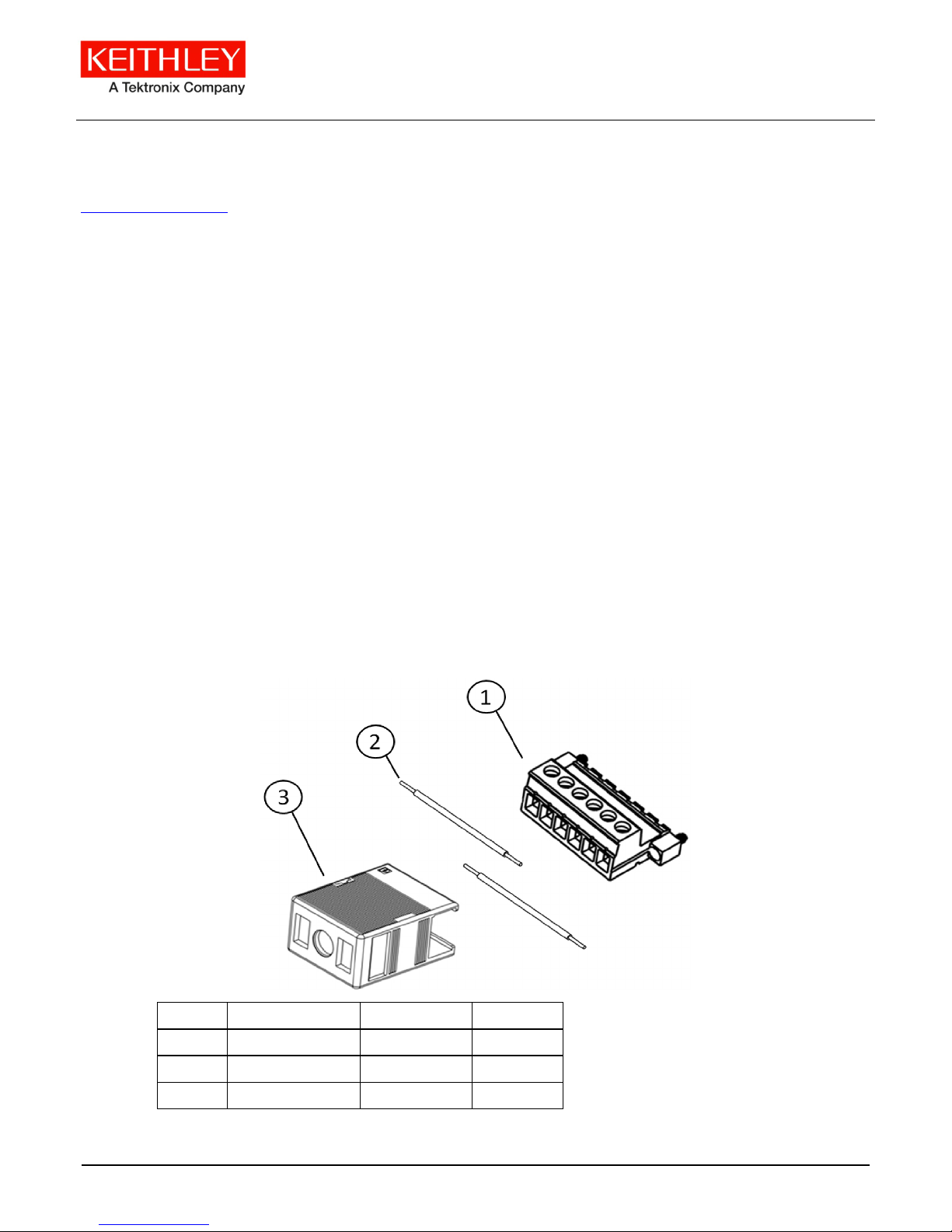
Parts list
The following figure shows the hardware supplied with this connector; the table below it contains part names,
numbers, and supplied quantities.
Figure 1: Model 2280-001 Output Mating Connector
Description Part number Quantity
1 Plug connector 131917500 1
2 Jumper wire 174656900 2
3 Cable housing 380126600 1
077085600 /June 2014 *P077085600* 1
Page 2
Model 2280-001 Output Mating Connector
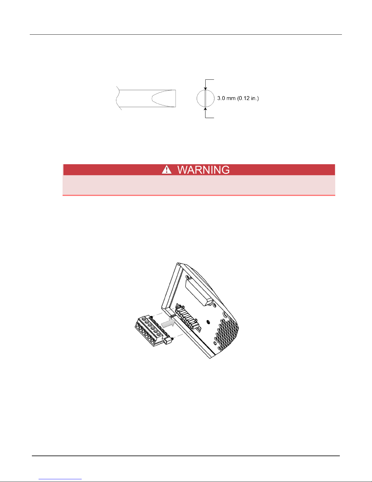
Tools required for installation
• Flat-head screwdriver
Figure 2: Screwdriver specifications
Installation precautions
Use the following procedure to install the Model 2280-001 Output Mating Connector.
Turn off instrument power before installing the mating connector to the instrument. Failure to
remove power before installation may cause personal injury or death from electrical shock.
Installing the M odel 2280-001 Output Mating Connector
To install the connector for 2-wire operation:
1. Power off the instrument.
2. Insert the plug connector into the female connector on the Series 2280.
Figure 3: Install the plug connector
2 077085600/June 2014
Page 3
Model 2280-001 Output Mating Connector
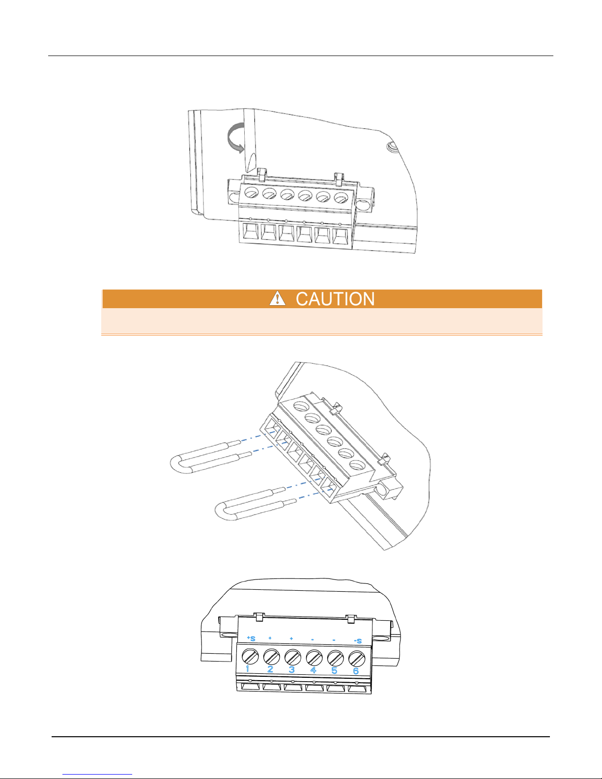
3. Loosen the flat head screws on the output mating connector
Figure 4: Loosen the screws
4. Insert the two jumper wires into the plug connector. One jumper goes in terminals 1 and 2 and the other goes in
terminals 5 and 6, as shown below.
Make sure that the jumpers connect to the correct pins on the plug connector. Incorrect connections
may cause instrument damage.
Figure 5: Install the jumper wires
Figure 6: Connector terminals
077085600/June 2014 3
Page 4

Model 2280-001 Output Mating Connector
5. Tighten the screws with the screwdriver.
6. Connect the output wires (Source HI is connected to terminal 3 and Source LO is connected to terminal 4, as
shown above).
7. Slide the cable housing over the output mating connector and wires.
The jumper cables must be installed if you are going to use 2-wire connections.
Even if you are using the front-panel connectors, the output mating connector (with jumper wires
installed) must be connected to the Series 2280 rear-panel output connector to ensure proper
instrument performance.
Figure 7: Install the output mating connector for 2-wire operation
To install the connector for 4-wire operation:
1. Power off the instrument.
2. Insert the output mating connector into the female connector on the rear panel of the Series 2280.
Figure 8: Install the plug connector
4 077085600/June 2014
Page 5

Model 2280-001 Output Mating Connector
3. Loosen the flat-head screws on the output mating connector.
4. Insert the source wires and the sense wires into the plug connector.
Make sure that the source and sense wires connect to the appropriate terminals of the plug connector
(Source HI is connected to terminal 2 and Source LO is connected to terminal 5; Sense HI is
connected to terminal 1 and Sense LO is connected to terminal 6). An incorrect connection may cause
instrument damage.
5. Tighten the screws with the screwdriver.
Figure 9: Install the output mating connector for 4-wire operation
6. Slide the cable housing over the output mating connector and wires.
077085600/June 2014 5
Page 6

6 077085600/June 2014
Safety precaut ions
The following safety precaut ions should be ob served before u sing this product and any associated in strumentation. A lthough some
instruments and accessories would normally be used with nonhazardous voltages, there are situations where hazardous
conditions may be present.
This product is intended for use by qualified personnel who recognize shock hazards and are familiar with the safety precautions
required to avoid pos sible injur y. Read a nd follow all install ation, oper ation, an d maintena nce inform ation carefu lly befor e using the
product. Refer to the user documentation for complete product specifications.
If the product is used in a manner not specified, the protection provided by the product warranty may be impaired.
The types of product users are:
Responsible body is the individual or group responsible for the use and maintenance of equipment, for ensuring that the
equipment is operated within its specifications and operating limits, and for ensuring that operators are adequately trained.
Operators use the product for its intended function. They must be trained in electrical safety procedures and proper use of the
instrument. They must be protected from electric shock and contact with hazardous live circuits.
Maintenance personnel perform routine procedures on the product to keep it operating properly, for example, setting the line
voltage or replacing consumable materials. Maintenance procedures are described in the user documentation. The procedures
explicitly state if the operator may perform them. Otherwise, they should be performed only by service personnel.
Service personnel are trained to w ork on live circuits, perform safe in stallations, an d repair produ cts. Only proper ly trained serv ice
personnel may perform installation and service procedures.
Keithley Instruments produ cts are designed for use with elect rical signals tha t are measurement, control, and da ta I/O connections,
with low transient overvoltages, and must not be directly connected to mains voltage or to voltage sources with high transient
overvoltages. Measurement Category II (as referenced in IEC 60664) connections require protection for high transient
overvoltages often associated with local AC mains connections. Certain Keithley measuring instruments may be connected to
mains. These instruments will be marked as category II or higher.
Unless explicitly allowed in the specifications, operating manual, and instrument labels, do not connect any instrument to mains.
Exercise extreme c aution w hen a s hock hazard is pres ent. L ethal v olt age m ay be prese nt o n cabl e connect or ja cks or test f ix tures.
The American National Standards Institute (ANSI) states that a shock hazard exists when voltage levels greater than 30 V RMS,
42.4 V peak, or 60 VDC are present. A good safety practice is to expect that hazardous voltage is present in any unknown circuit
before measuring.
Operators of this product must be protected from electric shock at all times. The responsible body must ensure that operators are
prevented access and/or insulated from every connection point. In some cases, connections must be exposed to potential human
contact. Product operat ors in these cir cumstances must be trained to protect th emselves from the r isk of electri c shock. If th e circuit
is capable of operating at or above 1000 V, no conductive part of the circuit may be exposed.
For maximum safety, do not touch the pro duct, test c ables, or any other instr uments while pow er is applied to the circuit un der test .
ALWAYS remove power from the entire test system and discharge any capacitors before: connecting or disconnecting cables or
jumpers, installing or removing switching cards, or making internal changes, such as installing or removing jumpers.
Do not touch any ob ject that could provide a curr e nt path to the common side of the circuit under test or power line ( earth) ground.
Always make measurements with dry hands while standing on a dry, insulated surface capable of withstanding the voltage being
measured.
For safety, instruments and accessories must be used in accordance with the operating instructions. If the instruments or
accessories are used in a manner not specified in the operating instructions, the protection provided by the equipm ent ma y be
impaired.
Do not exceed the maximum signal levels of the instruments and accessories, as defined in the specifications and operating
information, and as shown on the instrument or test fixture panels, or switching card.
Chassis connections must only be used as shield connections for measuring circuits, NOT as protective earth (safety ground)
connections.
The WARNING heading in the user d ocu me ntation explains dangers th at m ight res ult in personal injury or death. Always read the
associated information very carefully before performing the indicated procedure.
Page 7

077085600/June 2014 7
The CAUTION heading in the user documentation explains h az ards that coul d dama ge the instr ume nt. Such dam age may
invalidate the warranty.
Instrumentation and accessories shall not be connected to humans.
Before performing any maintenance, disconnect the line cord and all test cables.
To maintain protection from e lectric shock and fire, repla ce m ent co mpo nent s in mai ns circ u its — including the power tr ans former,
test leads, and input jacks — must be purchased from Keithley Instruments. Standard fuses with applicable national safety
approvals may be used if the rating and type are the same. Other components that are not safety-related may be purchased fr o m
other suppliers as long as t hey are equivalen t to the original c omponent (note t hat selected p arts should be purc hased only throu gh
Keithley Instruments to maintain accuracy and functionality of the product). If you are unsure about the applicability of a
replacement component, call a Keithley Instruments office for information.
To clean an instrument, use a damp cloth or mild, water-based cleaner. Clean the exterior of the instrument only. Do not apply
cleaner directly to the instrument or allow liquids to enter or spill on the instrument. Products that consist of a circuit board with no
case or chassis (e.g., a data acquis ition board for in stallation i nto a computer ) should never r equire cleaning if handled a ccording to
instructions. If the board becomes contaminated and operation is affected, the board should be returned to the factory for proper
cleaning/servicing.
Safety precaution revision as of January 2013.
 Loading...