

Page 1

Ninja ZX-6R
2008 Ninja ZX-6R
Racing Kit Manual
This manual contains only the information of the racing kit parts. Refer to the base
manual listed below for information of the original model.
Base Manual Part Number
Ninja ZX-6R
Motorcycle Service Manual
© 2008 Kawasaki Heavy Industries, Ltd. First Edition (1): Jan. 25, 2008
99924-1382-02
Page 2

Page 3

Congratulation on your purchase of racing kit parts for the 2008 Ninja ZX-6R.
IMPORTANT
This manual provides how to install racing kit parts for the 2008 Ninja ZX-6R and how to
tune up basically.
As for the basic knowledge, refer to the base Service Manual for the Ninja ZX-6R (P/No.
99924-1382-02).
When you participate in a race, it is necessary to modify the machine for the regulation.
So we want you to ask for the tuning up shop.
WARNING
AFTER ANY MODIFICATION TO TUNE THE VEHICLE TO A COMPETITION MACHINE,
IT SHOULD NOT BE USED ON PUBLIC STREETS, ROADS OR HIGHWAYS. THE USE
OF THIS VEHICLE SHOULD BE LIMITED TO PARTICIPATION IN SANCTIONED
COMPETITION EVENTS UPON A CLOSED COURSE.
CAUTION
When operating the engine, be careful not to trouble persons with noise. Do not turn the
engine with loud engine and exhaust noise.
DISCLAIMER OF WARRANTY
ON OPTIONAL TUNING PARTS FOR RACING ARE NO WARRANTIES EXPRESSED
OR IMPLIED.
BASIC WORKS IN INSTALLING KIT PARTS
We are going to make up the original Ninja ZX-6R for the racing machine. We
recommend that the rider himself should do the basic works, removing parts or installing
parts etc., given advices by the tuning shop. In a race, although trouble will be apt to
happen, if you participate in basic works, you can discriminate cause of trouble, so you can
return the race soon.
But concerning difficult technical works, you should as tuning shop.
1
Page 4

Dummy page
2
Page 5

Table of Contents
General Specifications ......................................................................................................4
Racing Kit Service Data ....................................................................................................6
Periodic Maintenance Chart .............................................................................................7
Preparation......................................................................................................................... 9
Before Installing ....................................................................................................................................9
Racing Kit Parts................................................................................................................. 9
Engine Parts Installation...................................................................................................9
Air Intake Parts .....................................................................................................................................9
Cylinder Head .....................................................................................................................................11
Camshaft Chain Tensioner..................................................................................................................12
Camshafts, Sprockets.........................................................................................................................13
Valve Springs......................................................................................................................................14
Cylinder Compression.........................................................................................................................14
Crankshaft Main Journal and Connecting Rod Big End Bushings ......................................................16
Connecting Rod Bolts .........................................................................................................................19
Clutch Adjustment (Back-Torque Limiter Setting)................................................................................20
Transmission.......................................................................................................................................24
Transmission Shimming ......................................................................................................................24
Generator (Option)..............................................................................................................................25
Generator Cover (Option) ...................................................................................................................25
Cover Gaskets ....................................................................................................................................25
Ducts (Air Funnels) .............................................................................................................................25
Muffler.................................................................................................................................................26
Water Temperature Sensor.................................................................................................................26
Radiator (Kit).......................................................................................................................................26
Oil Catch Tank Installation ..................................................................................................................30
Frame Parts Installation ..................................................................................................33
Throttle Parts (Kit)...............................................................................................................................33
Brake Pads (Kit)..................................................................................................................................34
Steering Damper (Kit) .........................................................................................................................34
Seat Height Adjustment ......................................................................................................................35
Front Fork Springs (Kit).......................................................................................................................37
Electric Parts Installation................................................................................................39
Battery ................................................................................................................................................39
Main Harness and Sub Harness (Kit) .................................................................................................39
Meter (Kit) Installation.........................................................................................................................40
Wiring Routing ....................................................................................................................................42
Wiring Diagram (with Kit Meter) .....................................................................................44
Wiring Diagram (with Original Meter Assembly)...........................................................46
3
Page 6

General Specifications
Item 2008 Ninja ZX-6R Racing
Engine:
Ignition timing 12.5°BTDC @1 300 r/min (rpm)
Fuel (Recommended) Racing gasoline
Engine oil (Recommended): Racing oil
Level Between upper and lower levels of oil level gauge.
Drive Train:
Primary drive reduction ratio 1.900 (76/40)
Transmission Gear Table
In 13127-0044 13127-0055
1st
2nd
3rd
4th
5th
6th
Out 13262-0507 13262-0526 13262-0535
Teeth (Out/In) 38/14 37/14 36/14
Gear Ratio 2.714 2.643 2.571
In 13262-0372 13262-0527 13262-0536 13262-0677
Out 13262-0508 13262-0528 13262-0537 13262-0678
Teeth (Out/In) 33/15 39/18 34/16 36/16
Gear Ratio 2.200 2.167 2.125 2.25
In
Out 13262-0509 13262-0683
Teeth (Out/In) 37/20 32/17
Gear Ratio 1.850 1.882
In
Out 13262-0510 13262-0530 13262-0684 13262-0685
Teeth (Out/In) 32/20 33/20 39/23 30/19
Gear Ratio 1.600 1.650 1.696 1.579
In 13262-0374 13262-0531 13262-0538 13262-0686
Out 13262-0380 13262-0532 13262-0539 13262-0687
Teeth (Out/In) 27/19 30/20 32/22 32/23
Gear Ratio 1.421 1.500 1.455 1.391
In 13262-0375 13262-0533 13262-0540 13262-0688
Out 13262-0582 13262-0534 13262-0541 13262-0689
Teeth (Out/In) 26/20 32/23 35/26 29/23
Gear Ratio 1.300 1.391 1.346 1.261
STD
(Type A)
See Gear
Selection
See Gear
Selection
Type B Type C Type D
(13127-0055)
See Gear
Selection
See Gear
Selection
See Gear
Selection
See Gear
Selection
4
Page 7
Input 3rd/4th Gear Selection Table
3rd Gear
A 13262-0506 13262-0529 13262-0679
B 13262-0680 13262-0681 13262-0682
A B C D
Gear Identification Slit Number Table
1st
2nd
3rd
4th
5th
6th
In 0 1 1
Out 0 1 2
In 0 1 2 3
Out 0 1 2 3
In 0 1
Out 0 1
In 0 1 2 3
Out 0 1 2 3
In 0 1 2 3
Out 0 1 2 3
In 0 1 2 3
Out 0 1 2 3
STD
(Type A)
4th Gear
Type B Type C Type D
5
Page 8

Racing Kit Service Data
Item Standard
Cylinder Head, Valves:
Duration:
Intake 288°
Exhaust 266°
Camshaft timing (cam lift center):
Intake 105° (ATDC)
Exhaust 110° (BTDC)
Valve clearance:
Intake 0.16 mm
Exhaust 0.28 mm
Valve to piston clearance:
Intake 0.80 mm (Minimum) @12°ATDC
Exhaust 1.40 mm (Minimum) @11°BTDC
Ignition System:
Spark plugs
Spark plug tightening torque 13 N·m (1.3 kgf·m, 113 in·lb)
NGK R0045Q-10, R0373A-10
These values show the specifications when standard cylinder head and gasket are used.
When the clearance between the valve and the piston head is smaller than the minimum
specific values, turn the installed position of the camshaft sprocket on the camshaft and
change the camshaft timing.
6
Page 9

Periodic Maintenance Chart
The scheduled maintenance must be done in accordance with this chart to keep the
motorcycle in good running condition.
FREQENCY
OPERATION
Engine
Clutch plate - - check* ●
Throttle grip play - - check* ●
Spark plug - - clean/gap* ●
Engine oil - - change ●
Oil filter - - replace ●
Valve lapping ●
Cylinder head/valve - - decarbonization ●
Cylinder - - check* ●
Piston/cylinder clearance - - check* ●
Piston, Piston ring, Piston pin - - replace ●
Crankshaft main bearing - - check* ●
Connecting rod big end bearing - - check* ●
Transmission gear, bearing - - check* ●
Engine sprocket - - check* ●
Coolant - - change ●
Radiator hoses, connections - - check* ●
Frame
Brake operation - - check* ●
Brake pad wear - - check* ●
Brake fluid level - - check* ●
Brake fluid - - change* year
Brake master cylinder cup and dust seal - - replace year
Brake caliper piston seal and dust seal - - replace year
Brake hose - - replace 2 years
Drive chain - - adjust ●
Drive chain - - lubricate ●
Drive chain wear - - check* ●
Drive chain guide - - replace If damaged
Front fork - - clean/check* ●
Front fork oil - - change First change after 2 races, then every 5 races
Nut, bolt, and fastener tightness - - check* ●
Fuel system - - clean ●
Fuel hose, fuel filter - - replace ●
Steering play - - check* ●
Steering stem bearing - - grease ●
Rear sprocket - - replace ●
General lubrication of chassis - - perform ●
Each
Race
(300 km)
Every
3 races
(1 000 km)
Every
5 races
(1 500 km) (3 000 km)
Every
10 races
As
Required
7
Page 10

FREQENCY
OPERATION
Wheel bearing (rear) - - grease ●
Swingarm pivot, uni-track linkage - - grease ●
Swingarm pivot, uni-track linkage - - check* ●
Each
Race
(300 km)
Every
3 races
(1 000 km)
Every
5 races
(1 500 km)
Every
10 races
(3 000 km)
As
Required
*: Replace, add, adjust, clean, or torque if necessary.
8
Page 11
Preparation
Before Installing
Modify the parts based on your race regulation.
To avoid misuse keep the parts replaced with the kit parts separate.
When reusing parts, clean them and check them for damage or deterioration.
Main Removal Parts:
Lights
Rear View Mirrors
Side Stand
Starter Lockout Switch
Remove the side stand switch. When the optional main harness is not used, connect
removing Black/Yellow and Green/White Leads directly.
Racing Kit Parts
Also, we have provided the spare parts, and other optional parts (engine, frame, and
electric parts) for racing. So please order each parts referring to the “Racing Kit Parts List”
in the back of this manual.
Engine Parts Installation
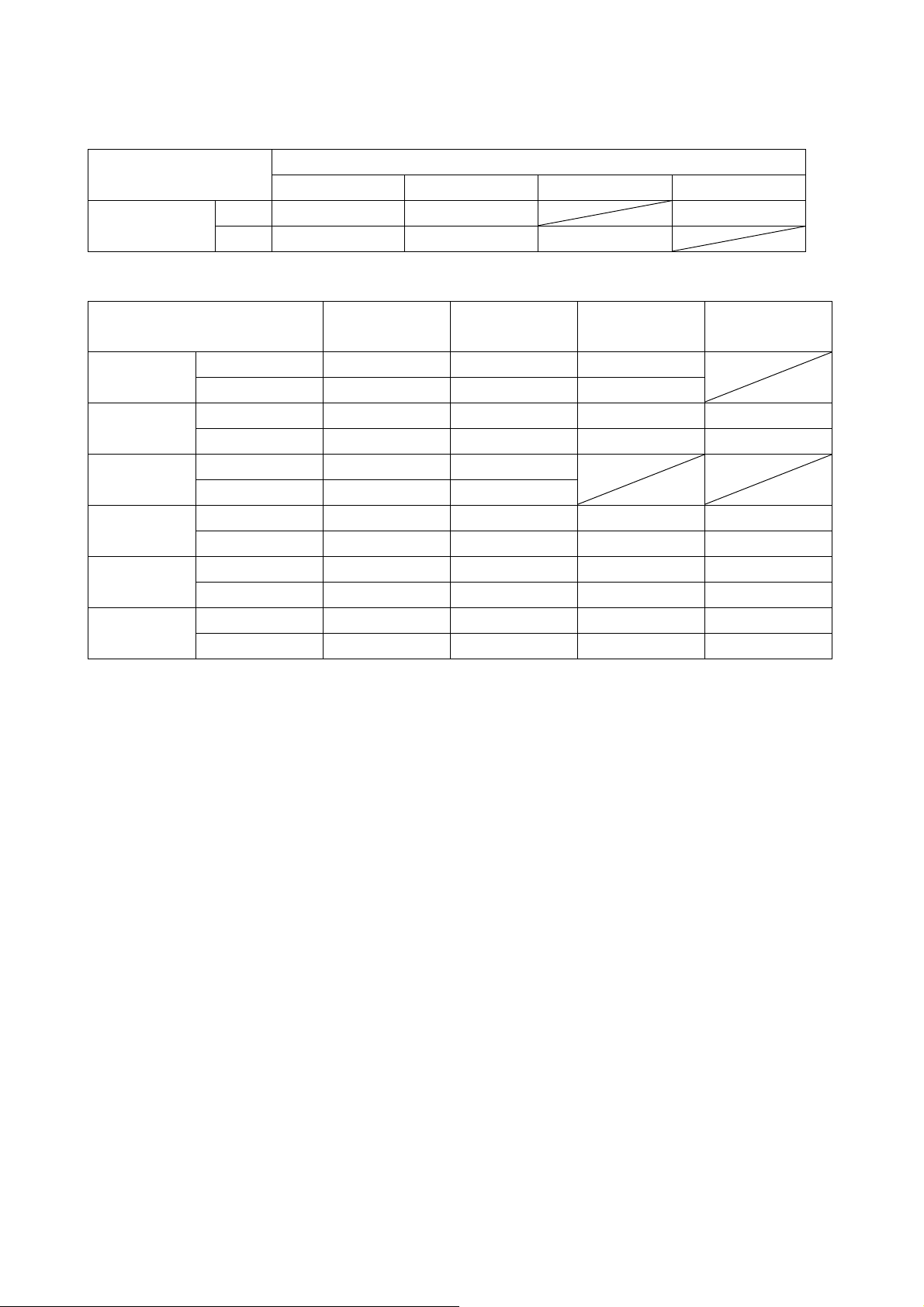
Air Intake Parts
Remove the wire net of Ram – Air duct intake to reduce the air flow resistance.
Remove the tank (16181-0011) to reduce the weight. Plug the holes firmly with a tape.
The air pressure in the duct rises during high speed operation because the Ram Air
System is used.
A. Wire Net (14037-0057)
B. Tank (16181-0011)
9
Page 12

Remove the secondary valves of cylinder head and relational parts, then plug the each
holes.
Remove the oil receiver and plug the hole.
Remove the air cleaner element or cut the cleaner element off remaining punched plate
to reduce the air flow resistance.
1. Remove the parts.
2. Plug the holes.
3. Replace with plugs (92043-1506), and plug the holes.
10
Page 13
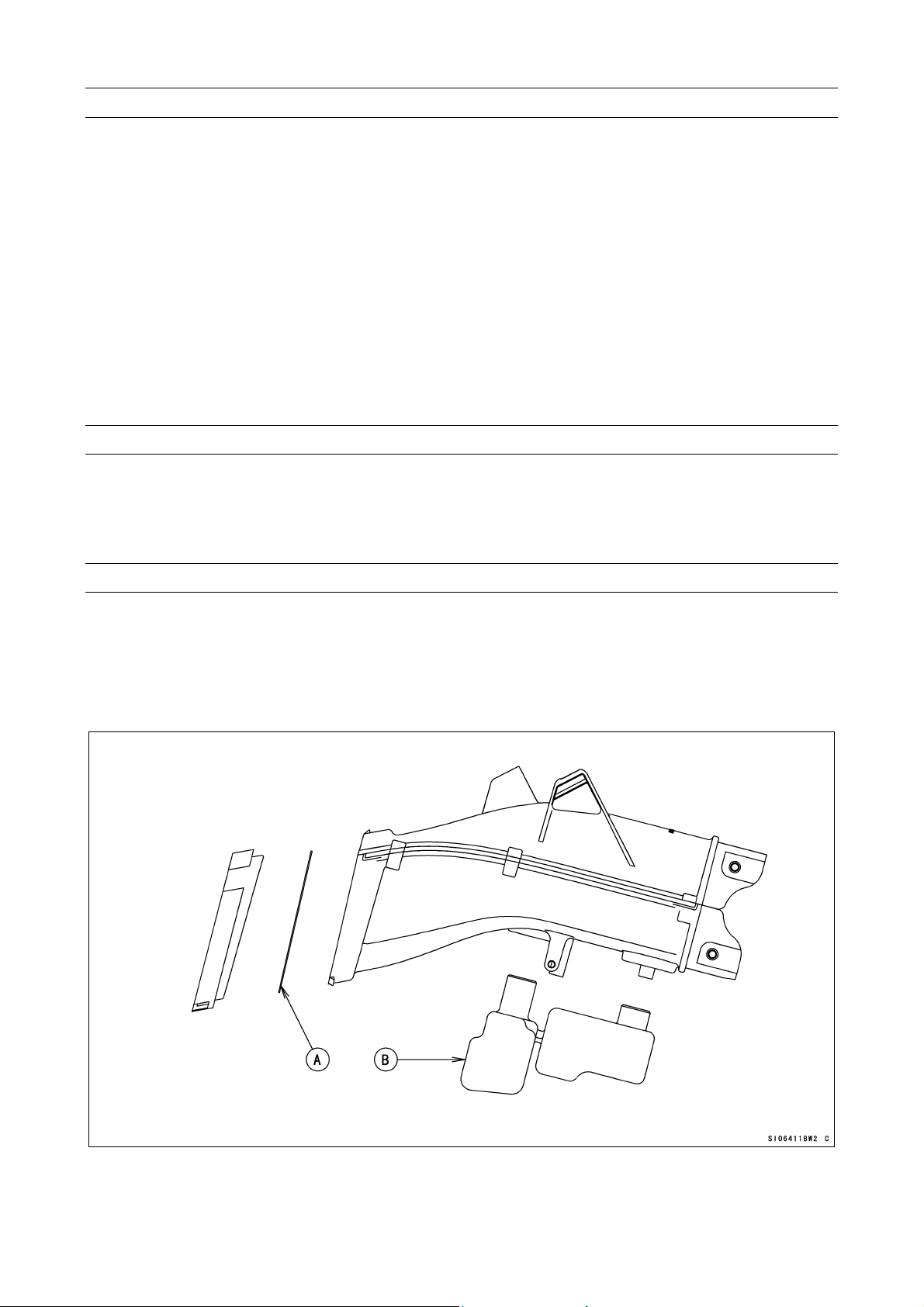
Cylinder Head
Grind off the stepped portions of the ports and smooth the inside of ports to make
intake/exhaust gas flow more smooth.
Grind off the stepped portion only at the mating surface between the carburetor holder
and the intake port. Do not port it. To extend the intake port, air flow speed will be
reduced and the engine performance at the high speed range may be down.
Mark the carburetor holders so that they can be installed in their original positions.
Grind off and smooth the stepped portions at the mating surface between valve seat and
the port.
Smooth the inside of the intake port and exhaust port.
Use the hand grinder.
Use #200 oil stone for eliminating any stepped portions.
Use #200 oil stone for smoothing and #300 oil stone for finishing.
NOTE
These procedures make air resistance less and intake/exhaust gas flow more smooth.
However, much more effect can not be expected by excessive grinding and smoothing.
It may be done to the extent of getting rid of uneven surfaces.
1. Stepped Portions of carburetor holder and cylinder head.
2. Stepped Portions of valve seat and cylinder head.
11
Page 14
The combustion chambers are modified by cutting work but the edges shown must be
hand finished for smooth corners (Round them to about R1).
Chamfer the machining edge of the cylinder head where the valve seat is installed, also
smooth the dome of the combustion chamber with the valves installed. Excessive
smoothing may reduce the cylinder compression.
XXX. Edges
NOTE
When grinding the cylinder head bottom surface or using thinner gaskets, adjust the
valve timing to keep that the valve to piston clearance is not less than the minimum
value (IN: 0.8 mm, EX: 1.4 mm).
Camshaft Chain Tensioner
Replace the cam chain tensioner with the kit to gain the durability.
Apply the engine oil to the tensioner rod, O-ring and tensioner body, insert them into the
tensioner body.
Check to see that the tensioner rod turns freely in the body, if not, polish the tensioner rod
or fine the female threads in the body with a tap (Diameter × Pitch = 6 mm × 1.0 mm).
Install the tensioner on the cylinder block with the tensioner rod is fully pushed back.
Turn the tensioner rod in with a screwdriver until it becomes hard to turn.
Turn the crankshaft clockwise forcing lightly to the tensioner rod with twisting force to
take up any gap and tighten the locknut.
Tighten the rock nut after adjustment.
NOTE
Never forward the tensioner rod forcibly, this will increase mechanical loss of the
tensioner and may damage to the chain guide.
The cam chain tensioner must be adjusted at every race.
12
Page 15
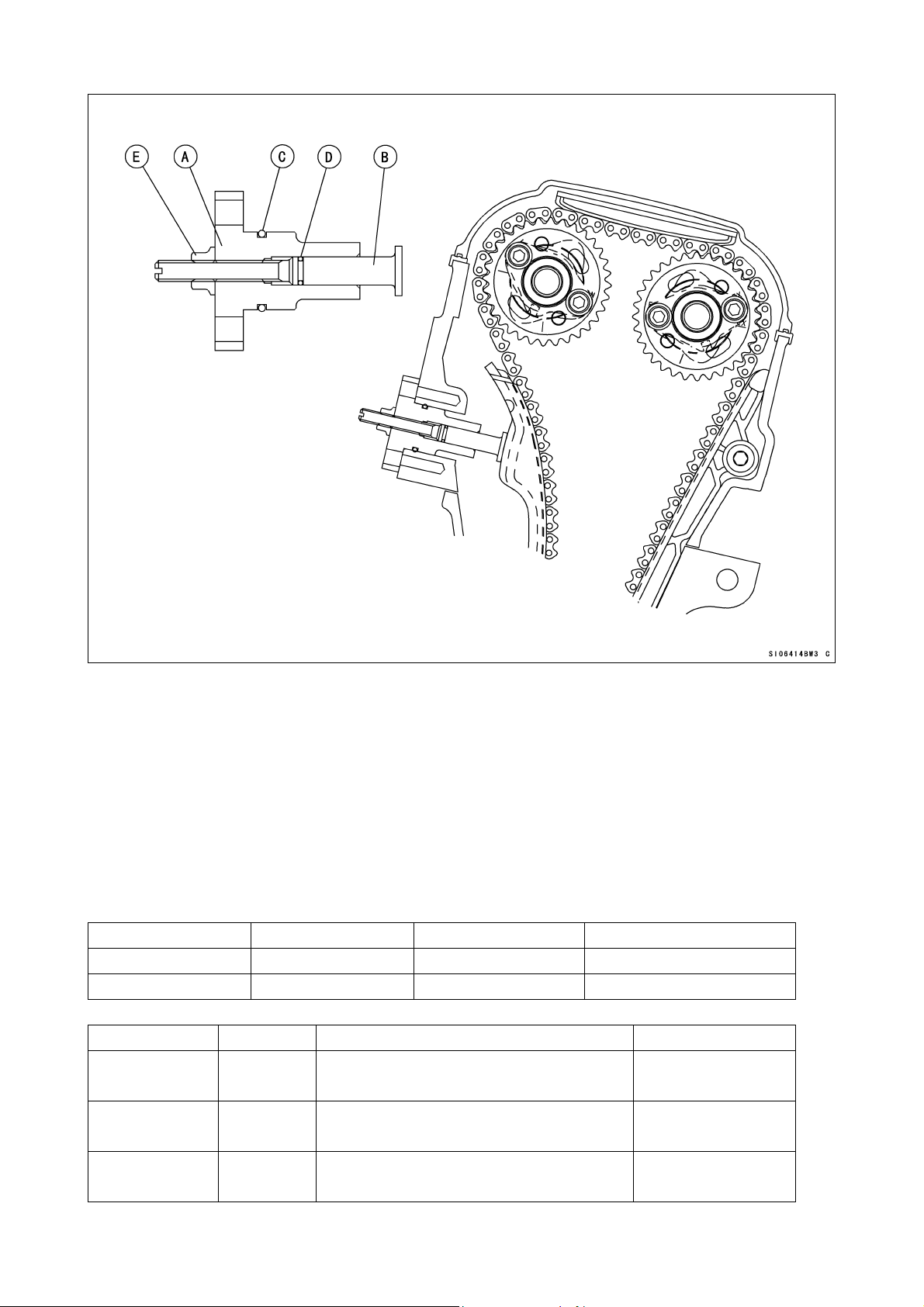
A. Tensioner
B. Tensioner Rod
C. O-ring
D. O-ring
E. Lock nut
Camshafts, Sprockets
Camshafts, Sprockets:
Adjust the valve clearance within the specified value, but more performance is expected
when adjusted from middle value to upper limit between adjustable range.
Original Timing Cam Lift Valve Clearance
Intake 288° 8.30 mm 0.13 ∼ 0.19 mm
Exhaust 266° 7.50 mm 0.24 ∼ 0.31 mm
Kit Timing Cam Lift Valve Clearance
Intake
49118-0110
Exhaust
49118-0111
Exhaust
49118-0120
308°
274°
274°
(conformed to FIM regulation)
(not conformed to FIM regulation)
(conformed to FIM regulation)
8.30 mm
7.30 mm
7.50 mm
0.13 ∼ 0.19 mm
0.24 ∼ 0.31 mm
0.24 ∼ 0.31 mm
13
Page 16

If you don’t adjust the valve timing for racing, install the camshaft sprocket to the kit
camshaft using the round bolt holes and adjust the cam chain timing according to the
Ninja ZX-6R Service Manual. If you adjust the valve timing, install the sprocket to the
camshaft between the adjustable range of the long bolt holes.
Tighten the camshaft sprocket bolts to 15 N·m (1.5 kgf·m, 11.0 ft·lb) of torque.
Valve Timing (when the round bolt holes are used)
Timing (cam lift center) Intake Exhaust
Original 105° 110°
Race use 105° 110°
When grinding the cylinder head bottom surface, grinding the cylinder top surface or
using thinner gaskets, be sure the valve to piston clearance especially.
When using the sprocket long bolt holes and adjusting the valve timing to be different
from the standard timing, check the valve to piston clearance of all cylinders after
adjusting the valve clearance correctly.
Valve to Piston Clearance (Min.)
Intake 0.8 mm
Exhaust 1.4 mm
If the valve to piston clearance is less than the minimum value, do not start the engine
because the valves will touch the piston and the engine may be damaged.
Measure the valve to piston clearance at about 12° ATDC (Intake) and 11° BTDC
(Exhaust) of crankshaft timing. At this point, the valve to piston clearance will be
minimum.
Valve Springs
The original machine’s valve springs should be used
.
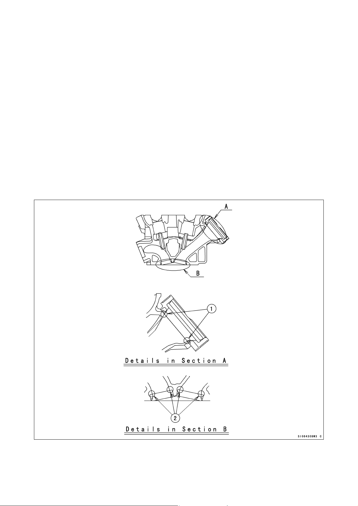
Cylinder Compression
To adjust the cylinder compression, adjust the thickness of the cylinder head gasket and
the cylinder base gasket or smooth the cylinder top surface to make the piston squish
0.65 ~ 0.8 mm. Keep the piston squish more than 0.65 mm.
Position the piston at Top Dead Center, and put a small piece of modeling clay on the
shoulder of the piston. Install the cylinder head gasket and cylinder head, and tighten
the head bolts to the specified torque.
Remove the cylinder head and measure the thickness of the clay. The thickness of the
collapsed clay is the size of the squish.
Squish Measurement
[1] Front and Rear 0.65 ~ 0.80 mm
[2] Left and Right 0.67 ~ 0.85 mm
The most preferable squish measurement is [1] 0.65 mm/[2] 0.67 mm.
Select proper cylinder head gasket and cylinder base gasket.
Note that by grinding the cylinder head surface only left and right squishes become
narrower, while by grinding the cylinder top surface or decreasing the gasket-thickness
all the squishes become narrower.
14
Page 17

Cylinder Head Gasket
Part No. Thickness Note
11004-0071 0.45 mm KIT
11004-0070 0.50 mm KIT
11004-0069 0.55 mm KIT
11004-0068 0.60 mm KIT
11004-0057 0.65 mm Original
11004-0067 0.70 mm KIT
1. Squish, Front/Rear
2. Squish, Left/Right
15
Page 18
Crankshaft Main Journal and Connecting Rod Big End Bushings
To adjust clearance of crankshaft main journal you can select proper bush in accordance
with the marks.
The kit bushings are improved in anti-seizuring characteristics as well as in
wear-resistance as compared with the standard bushings.
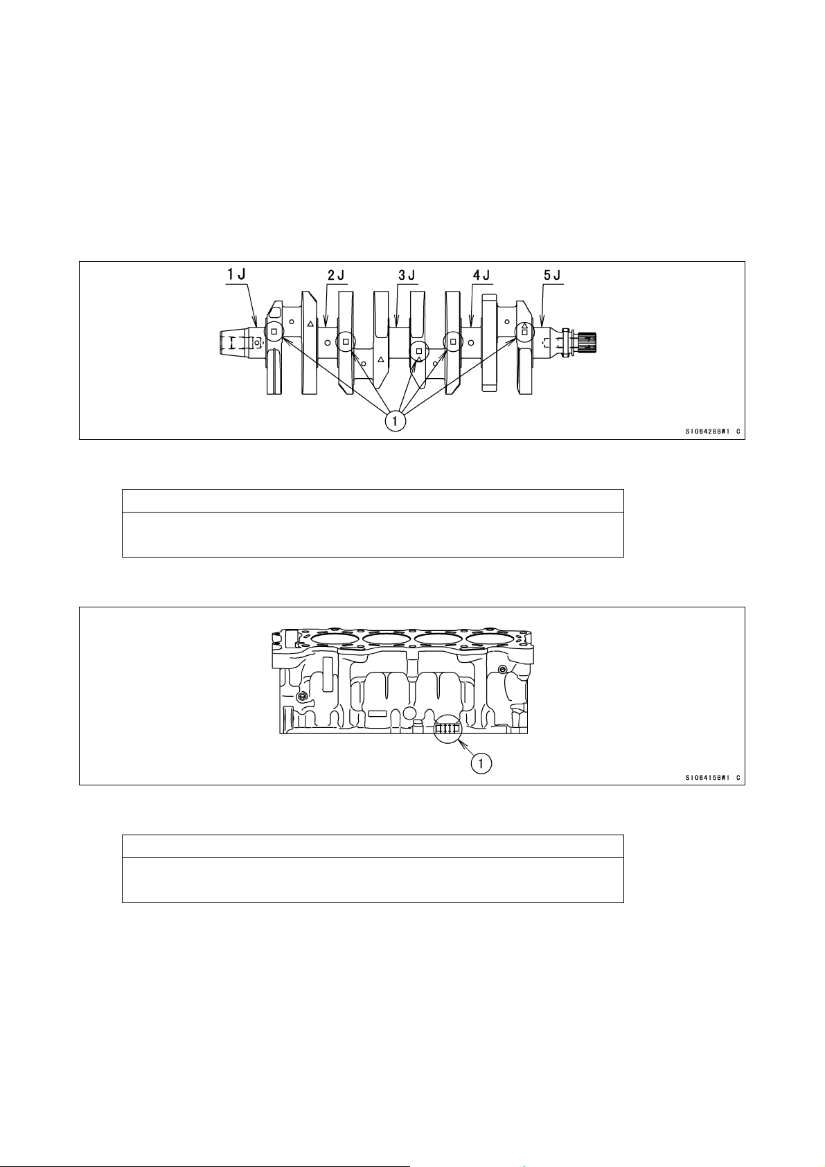
1) Crankshaft Main Journal
Crankshaft Main Journal Diameter
1. Crankshaft Main Journal Diameter Marks
SIZE
“1” mark : over 30.992 mm within 31.000 mm
None : over 30.984 mm within 30.992 mm
Crankcase Main Journal inside Diameter
1. Main Journal Diameter Marks
“{” mark : over 34.000 mm within 34.008 mm
None : 34.008 mm and over within 34.016 mm
SIZE
16
Page 19
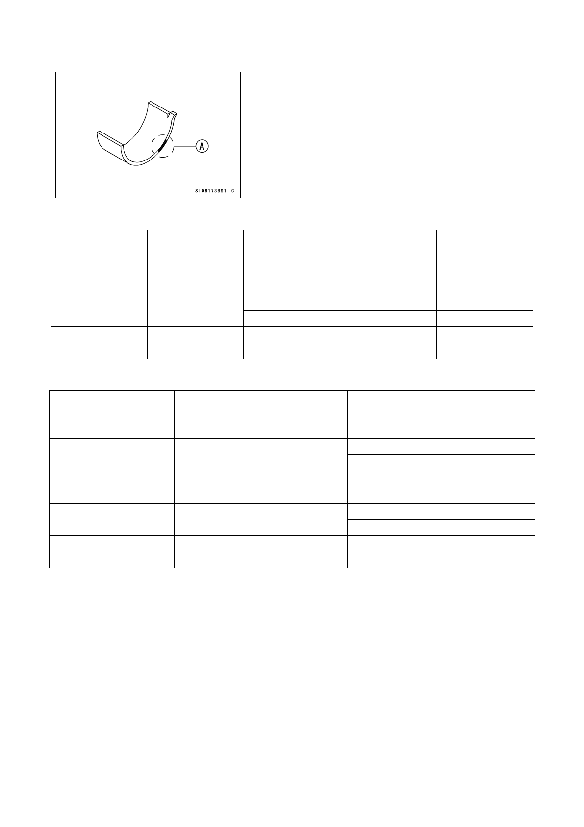
Main Journal Bush
A. Size Color
Size Color Thickness mm Journal Number
blue 1.499-1.503
1-4 92139-0189 92139-0200
5 92139-0171 92139-0197
black 1.495-1.499
1-4 92139-0190 92139-0201
5 92139-0172 92139-0198
brown 1.491-1.495
1-4 92139-0191 92139-0202
5 92139-0173 92139-0199
Selection Table
Crankcase inner Diameter Crankshaft Diameter
○
(34.000 mm ~ 34.008 mm) (30.992 mm ~ 31.000 mm)
○
(34.000 mm ~ 34.008 mm) (30.984 mm ~ 30.992 mm)
NONE 1 1-4 92139-0190 92139-0201
(34.008 mm ~ 34.016 mm) (30.992 mm ~ 31.000 mm)
NONE NONE 1-4 92139-0189 92139-0200
(34.008 mm ~ 34.016 mm) (30.984 mm ~ 30.992 mm)
1 1-4 92139-0191 92139-0202
NONE 1-4 92139-0190 92139-0201
Size
Color
brown
black
black
blue
Part Number
(STD)
Journal
Number
5 92139-0173 92139-0199
5 92139-0172 92139-0198
5 92139-0172 92139-0198
5 92139-0171 92139-0197
Part Number
(KIT)
Part
Number
(STD)
Part
Number
(KIT)
17
Page 20
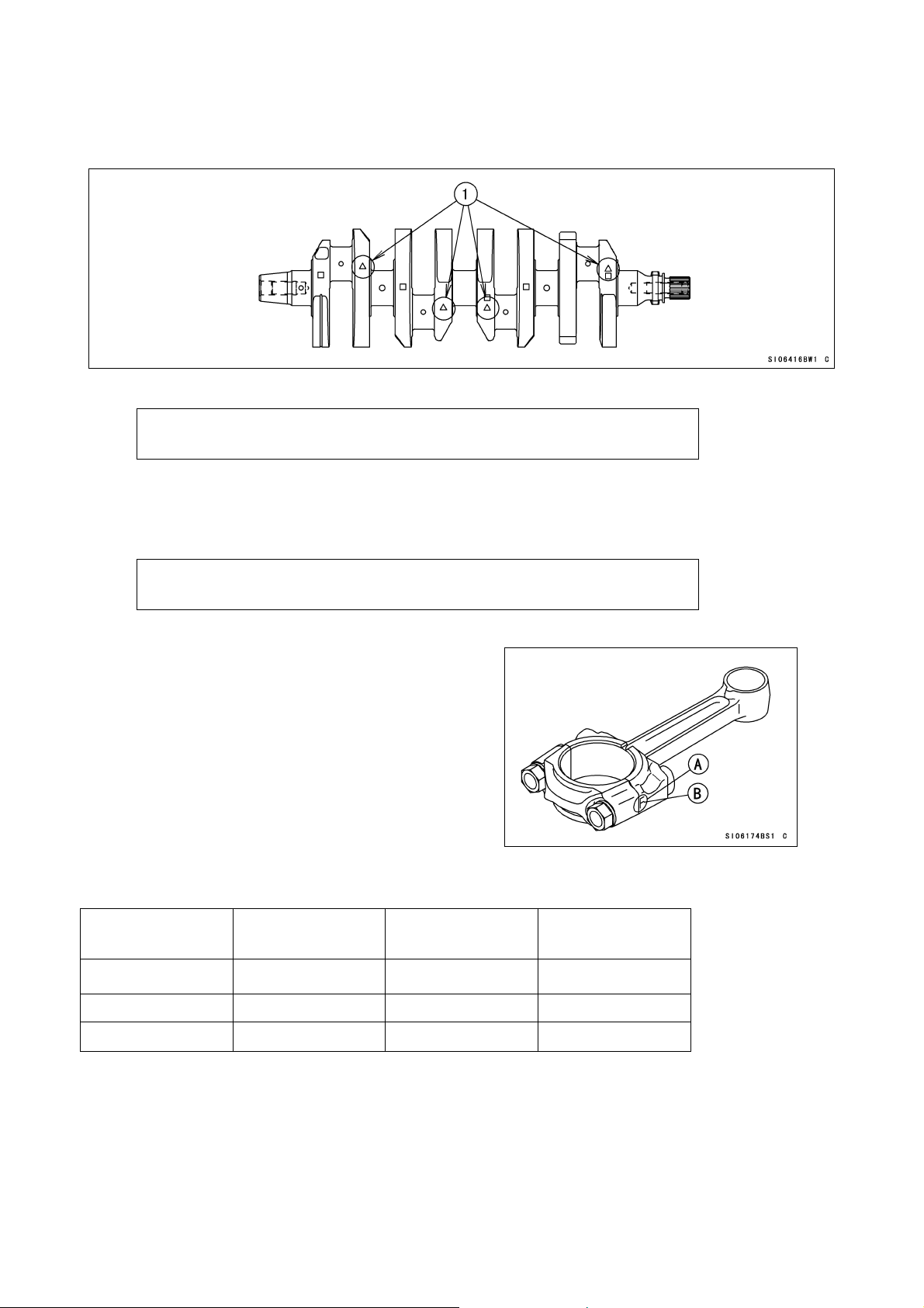
2) Crankpin
Crankpin Diameter
1. Crankpin Diameter Marks
“{” mark : over 29.992 mm within 30.000 mm
None : 29.984 mm and over within 29.992 mm
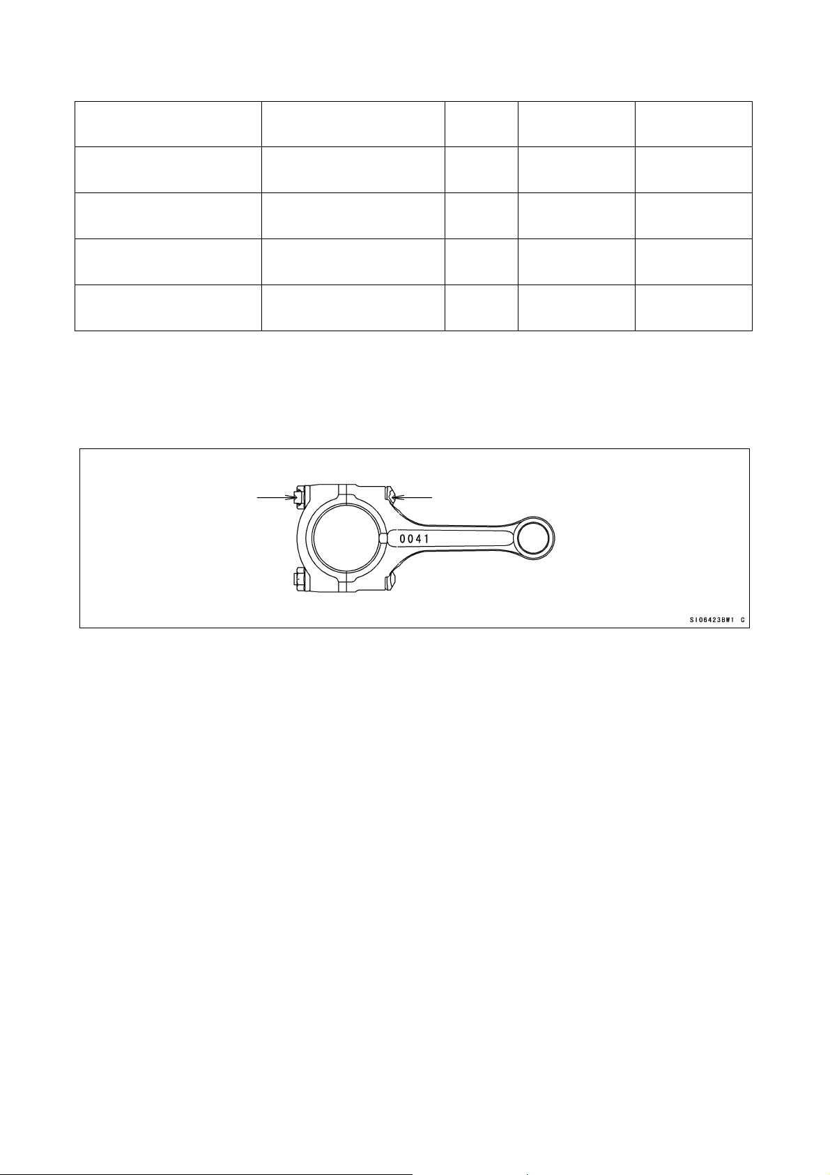
Connecting Rod Big End Inside Diameter
Connecting Rod Big End Inside Diameter Marks
“{” mark : over 33.008 mm within 33.016 mm
None : 33.000 mm and over within 33.008 mm
A. Inside Diameter Mark
({ or None)
B. Weight Mark, Alphabet
(G.H etc)
Connecting Rod Big End Bushings
Size Color Thickness mm
Part Number
(STD)
Part Number
(KIT)
blue 1.485-1.490 92139-0165 92139-0194
black 1.480-1.485 92139-0166 92139-0195
brown 1.475-1.480 92139-0167 92139-0196
18
Page 21
Selection Table
Connecting Rod Big End
Inside Diameter
None
(33.000 mm ~ 33.008 mm) (29.992 mm ~ 30.000 mm)
None None
(33.000 mm ~ 33.008 mm) (29.984 mm ~ 29.992 mm)
○ ○
(33.008 mm ~ 33.016 mm) (29.992 mm ~ 30.000 mm)
○
(33.008 mm ~ 33.016 mm) (29.984 mm ~ 29.992 mm)
Crankpin Diameter Mark
○
None
Size
Color
brown 92139-0167 92139-0196
black 92139-0166 92139-0195
black 92139-0166 92139-0195
blue 92139-0165 92139-0194
Part Number
(STD)
Part Number
(KIT)
Connecting Rod Bolts
Use the original connecting bolts and nuts.
The original connecting rod bolt has recesses at both ends to measure its length and
determine the bolt stretch.
Install the original bolts into the connecting rod.
Before every tightening, use a point micrometer to measure the length of the bolts and
record the values to find the bolt stretch.
Apply a small amount of molybdenum disulfide grease to the threads of bolts.
Tighten the big end nuts at the torque of 11.8 ±2 N·m (1.2 ±0.2 kgf·m): reference
Check the length of the bolts and find the bolt stretch.
Bolt Length after tightening – Bolt Length before tightening = Stretch
Bolt Stretch
Usable Range: 0.33 ~ 0.38 mm (0.013 ~ 0.015 in.)
Turn the big end nuts more until the bolt stretch reaches the usable range.
NOTE
Replace the original bolts with new ones if they have already been tightened up to usable
range 2 times.
19
Page 22

Clutch Adjustment (Back-Torque Limiter Setting)
The Ninja ZX-6R engine is equipped with the Kawasaki back-torque limiter mechanism in
the clutch. The back-torque limiter works to reduce the chance of rear wheel hop caused by
engine braking during hard braking and down shifting. The back-torque limiter operating
condition can be changed by changing the total thickness of clutch plates and changing the
number of leaf springs. Try different settings and select the best.
20
Page 23

The standard setting of length [A], total thickness of clutch plates shown in the illastration,
becomes about 40.7 mm. For this setting the effective stroke of clutch spring plate during
the back-torque limiter operation is adjusted between 0.45 and 0.75 mm. By increasing
the effective stroke the back-torque limiter causes more slip. The effective stroke
increases by decreasing the length [A]. The length [A] between 39.5 and 40.7 mm is
available by changing the combination of the steel plates. Replace one steel plate with a
thinner one and try the setting. If the operation of the back-torque limiter is not enough
replace other steel plates one by one.
* Steel plates of former model’s are available.
Thickness (mm) Part Number
2.0 13089-1073
For precise setting the measurement of the effective stroke of clutch spring plate is
recommended.
• Remove oil from clutch plates.
• Hold an extra drive shaft in a vise and install the following clutch parts on the shaft.
21
Page 24

Recommended Clutch
[A] Spacers
[B] Needle Bearing
[C] Bushing
[D] Clutch Outer Casing
[E] Clutch Hub
[F] Sub Clutch Hub
[G] Friction Plates: total 8 pcs.
[H] Steel Plates
[I] Spring Plate
[J] Steel Plate with Spring
22
Page 25

• Engage the cam followers (Clutch Hub) with the cams (Sub Clutch Hub).
• To measure the effective stroke of clutch spring plate, set a dial gauge [A] against the raised
center [B] of the clutch spring plate.
• Move the clutch housing gear back and forth [C]. The difference between the highest and
lowest gauge readings is the amount of the effective stroke of clutch spring plate.
[D] Drive Shaft
After installing the clutch to the engine, measure and record the depth [B] shown in the
figure on page 21 and 22. The length from the clutch spring plate to the top surface of the
sub clutch hub, using a caliper or a depth gauge. Manage the depth [B] to adjust the
effective stroke after that, because the friction disks would be worn and the length [A]
(Total thickness of all clutch plates) would change. The decrease of the depth [B] from
the initial setting shows the increase of the effective stroke of clutch spring plate from the
value initially measured.
When decreasing the length [A], total thickness of clutch plates, use the optional spring
retainers (provided as optional production parts) to keep the preload of clutch springs
according to the table below. If you have clutch slip during acceleration use shorter
spring retainers by 1 mm to increase preload of clutch springs.
When decreasing the length [A], total thickness of clutch plates, use the optional shim
(provided as optional production part) to keep the position of clutch release lever
according to the table below.
The standard setting of the number of leaf springs is four. By decreasing the number of
the leaf springs the sub clutch hub operates easily and pushes the clutch operating plate
causing more slip. Two types of nuts are available for the number of leaf springs, two and
three. They are provided as optional production parts. The number of leaf springs affects
all over the operation of the back-torque limiter but especially the beginning of the
operation.
Standard Selection of Spring Retainers
Total Thickness of Clutch Plates Size of Spring Retainers Remarks
40.2 ~ 40.7 mm 6 mm
P/No. 13091-1041
Original Setting
39.5 ~ 40.2 mm 5 mm P/No. 39108-0004
* If clutch slip is occurred with a retainer of 6 mm, try with a retainer of 5 mm.
23
Page 26

Standard Selection of Shim
Total Thickness of Clutch Plates Size of Shim Remarks
Approx. 40.7 mm 2.0 mm
P/No. 92180-0149
Original Setting
40.2 mm 1.5 mm P/No. 92026-1590
39.5 ~ 40 mm 1.2 mm 92025-1137
Transmission
Remove the three steel balls (600A0500) from the output shaft assembly.
Take kit and optional transmission gears are available to be closer to each gear ratio.
Transmission Shimming
By using washers with various thickness, keep the axial clearance between 0.3 mm and
0.5 mm, to prevent the seizure of gears and to keep smooth gear-shifting.
Thickness Part No.
1.6 mm 92200-0050 Original
Spline washer (input)
Plane washer
(input, output)
1.8mm 92200-0231 Kit
1.4 mm 92200-0230 Kit
1.4 mm 92200-0138 Original
1.6 mm 92022-212 Production part
1.8 mm 92202-1722 Production part
1. Spline washer (input)
2. Plane washer
24
Page 27

Generator (Option)
To quicken response by reducing the flywheel mass and to reduce the weight, use the
optional inner rotor generator.
Select using the optional generator or original generator according to the situation.
Use the optional regulator and optional generator cover set when using the optional
generator.
The output power of the optional generator is 10A/8000 rpm (Original: 30A/5000rpm).
The consume current of the racing model in running condition is 7 ~ 8A.
Installing Option Generator
Generator Cover (Option)
Use the option generator with the optional generator cover.
NOTE
When using the optional generator cover, use the optional generator.
Cover Gaskets
The optional cover gaskets are available.
They are made from “meta-form” and made easy to exfoliation.
Ducts (Air Funnels)
Select suitable combination for target characteristic of engine.
Length (mm)
15 14073-0124 Option
20 14073-0125 Option
30 14073-0174 Option
40 14073-0151 STD
50 14073-0152 STD
Part Number
25
Page 28

Muffler
With recommended muffler engine performance can be improved.
Recommended muffler: Beet NASSERT-R 1002-E02-00
Web Site : http://www.beet.co.jp/(beetjapan)
* For further information contact the manufacturer of muffler directly.
Water Temperature Sensor
The original water temperature sensor installed in the cylinder head must be remain and
connected to the main harness because the electronic control unit (E.C.U.) needs the
output signal from the original water temperature sensor. The optional tachometer is
equipped with a water temperature display. Install the optional water temperature sensor to
the optional water pipe and connect the sensor and the optional meter unit with the optional
harness.
Radiator (Kit)
’05 model ZX-6RR and ’08 ZX-6R Racing Kit provides the capacity increased main
radiator (39060-0020) to improve cooling performance.
26
Page 29

Radiator Installation
Use the radiator stay (35063-0439) and bracket (11054-1818) belong to kit, and fasten
the radiator to the Crankcase by bolts as shown in the figure.
Stay has several installation holes. Install position is adjustable for proper position of
radiator.
Some muffler may interfere with stay. In such case, make appropriate stay yourself.
Machine the original cowl to meet the outline of radiator.
Standard Resave tank is not available. Use some appropriate tank.
Fill the space between the cowl and the sides of radiator by fixing a sponge or the like.
NOTE
After radiator’s installation, be sure to check that there is no interference between the
radiator and the manifold, or fender, tire and the front fork full bottomed.
If you don’t use water temperature meter, use standard pipe, not oil cooler hose
(39062-0220). Nipple of radiator is plugged by CAP (11065-1056).
27
Page 30

Water Hose Installation
Radiator inlet
Divide the original water hose (39062-0156) at suitable position, and insert the hose
between cylinder head and radiator.
1. Water Hose 39062-0156
Insert the water hose (39062-0220) between oil cooler outlet and radiator.
Radiator outlet
Apply a non-permanent locking agent to the thread of the water temperature sensor (Kit:
for Meter Lamp). Mount the sensor on the pipe (39192-0011).
Insert the ground terminal of the water temperature sensor lead between the hose and
the pipe, and clamp the hose as shown in the figure. Fasten the another terminal to the
cover (generator) by the bolt.
* If you don’t use water temperature meter, use standard pipe and hose at oilcooler outlet
side and cover it radiator side with cap (11065-1056).
28
Page 31

1. Water Hose 39062-0219 4. Sensor 21176-1099
2. Ground Wire 26011-0071 5. Lead Wire 26011-1779
3. Water Hose 39062-0166 (Standard) 6. Clamp 92171-0179
Reserve Tank Installation
When using the radiator (Kit), the original reserve tank cannot be used. Prepare a
suitable substitue.
Reserve Tank should be equipped with a band so as not to affect the running and the
handling.
NOTE
Capacity of a reserve tank should be more than
200 cc.
Position of the hose to a reserve tank.
* End of the hose to the radiator should be always
in the liquid.
* End of the hose to atmosphere should be always
beyond the liquid surface.
29
Page 32

Oil Catch Tank Installation
Fasten the Bracket (E) to the Engine Hanger by using bolt (D).
Fasten Oil Catch Tank (A) to the Bracket (E) by using bolt (F) and nut (I).
Connect Air Cleaner, Crankcase and Oil Catch Tank by using hose1 (B) and hose2 (C).
A) Oil Catch Tank (52001-0004)
B) Hose1 (Air Cleaner – Oil Catch Tank)
C) Hose2 (Crankcase – Oil Catch Tank)
D) Bolt (130BA0835 standard)
E) Bracket (11054-1799)
F) Bolt (120P0620)
G) Dumper (92075-277)
H) Collar (92027-194)
I) Nut (92015-1193)
J) Washer (92022-304)
K) Drain Bolt (130Y0610)
30
Page 33

Hose1 (B) and Hose2 (C) assembling
Divide Hose (92059-1587, KIT) and Hose (92059-1629, KIT) as shown below.
Divide installed tube (92192-0429, standard) as shown below.
31
Page 34

Assemble hoses as shown below
5. Fitting (92005-0080)
32
Page 35

Frame Parts Installation
Throttle Parts (Kit)
The following throttle cases, grip and reels are available as optional parts. These optional
parts quicken throttle response to the twist grip.
1) Throttle Case
Parts P/No.
Throttle Case, Upper 32099-0004
Throttle Case, Lower 32099-0005
Bolts (2) 120S0625
Grip, Right 46075-1143
2) Throttle Reels
Tow types are available.
P/No. I.D. Mark
59101-0001 R21.5 60°
59101-0002 R20.0 65°
Throttle Reel Travel Angle················Effective angle excluding throttle cable free play.
Twist Grip Turn Angle
to Full Throttle
1. Identification Mark
1. Upper Case: 32099-0004
2. Lower Case: 32099-0005
3. Reel, 60°: 59101-0001
4. Reel, 65°: 59101-0002
5. Throttle Cable, Open Side: 54012-0232
6. Throttle Cable, Close Side: 54012-0233
7. Bolt: 120S0625
8. Gap
33
Page 36

1) Drive Chain
#520 Joint endless drive chain is available as an optional parts.
2) Chain Guard
1. Guard: 55020-0028
2. Bolt: 130J1020
3. Swingarm (Left Side)
Brake Pads (Kit)
The front and rear brake pads for racing use are available. The front pads are for higher
braking force, and the rear pads are for lower braking force.
Front Brake Pads
P/No. Mark Braking Force
43082-0074 2508 High
Original TT2172HH Low
↨
Rear Brake Pads
P/No. Mark Braking Force
Original FO GG High
43082-1220 C93G
43082-1192 G196 Low
↨
Steering Damper (Kit)
The steering damper is useful at high speeds to prevent handlebar vibration.
The steering damper should be installed to do not the steering handle movement stop by
the steering damper itself at the fully locket position both left and right side.
(Steering angle should be controlled by the regulation)
34
Page 37

1) Recommended Steering Damper
OHLINS SD121
Set the steering damper to the holder as shown.
2) Stroke(s)
SD121: 68 mm
1. Steering Damper: OHLINS SD121
2. Bracket: 11054-1816
3. Bracket: 11054-1817
4. Collar: 92152-0589
5. Ring: 670 B 2012
6. Washer: 410 B 0800
7. Bolt, Socket: 120 CA0630
8. Bolt, Socket: 120 CA0825
9. Bolt, Socket: 120 CA0865
10. Nut: 92105-1397
Seat Height Adjustment
Loosen the nut (1) and insert the spacer (2) as required.
Tighten the nut (1) to 59 N·m (6.0 kgf·m, 43 ft·lb) of torque.
One turn of the spring adjusting nut changes the spring length by 1.5 mm.
Rear Suspension Condition of Seat Height Adjustment
When the seat height adjusts spacer applied, the rear suspension should be softened.
Seat Height Adjustment
Spacer Set: 92026-1586
P/No. Quantity Thickness
92026-1582 1 1.0 mm
92026-1583 1 2.0 mm
92026-1584 1 3.2 mm
92026-1585 2 4.5 mm
35
Page 38

1. Nut 3. Collar
2. Spacer 4. Bracket
36
Page 39

Front Fork Springs (Kit)
The optional front fork springs are available for racing.
1) Front Fork Specifications
Items Original
Rebounded damping setting (Upper) 1 1/2 turns out from the fully clockwise position
Compression damping setting (Lower) 1 1/2 turns out from the fully clockwise position
Fork oil SHOWA SS47
Fork oil level 97 mm
Oil lock Oil lock piece
Oil seal – – –
Spring length 257.0 mm (Free Length)
Spring constant 9.0 N/mm
Sub spring stroke 28 mm
2) Front Fork Spring
P/No. A × B × C (mm) Number of Winding Spring Constant
Original 4.7 × 31.5 × 257.0 17.5 K = 9.0 N/mm
92145-0507 4.6 × 31.6 × 257.0 16.9 K = 8.25 N/mm
92145-0508 4.7 × 31.5 × 257.0 16.6 K = 9.25 N/mm
92145-0509 4.8 × 31.4 × 257.0 17.3 K = 9.75 N/mm
A: Coil Diameter
B: Spring Inside Diameter
C: Spring Free Length
3) Front Fork Spring Replacement
Replace the main spring referring to the Fork Oil Change section of the base Service
Manual.
Identification Mark
The spring constant value is stamped on the one side surface of the spring.
37
Page 40

Fork Spring Installation
38
Page 41

Electric Parts Installation
Battery
Use the original battery or a battery with 12 V 7 Ah or more capacity.
Main Harness and Sub Harness (Kit)
Main harness and sub harness are available for racing use as optional parts. Select one
of them in accordance with your race regulation.
Main Harness (with Optional Meter): 26031-0559
Main Harness (with Original Meter): 26031-0558
Sub Harness (with Original Meter and Original Main Harness): 26031-0327
(Immobilizer non-installed model only)
This set can not apply to the immobilizer installed model. For immobilizer
installed model, apply the main harness of part number 26031-0058 or
26031-0559.
39
Page 42

Meter (Kit) Installation
1. Tachometer with Water Temperature Gauge (Optional): 25031-1142
2. Collar (Optional): 92152-0058
3. Pad (Optional): 39156-0098
4. Bracket (Optional): 11053-1749
5. Rivet (Optional): 92039-1106
6. Nut (Optional): 92015-1233
7. Collar (Optional): 92152-1074
8. Bolt (Optional): 130J0625
9. Damper (Original): 92160-1167
10. Lamp Assembly (Optional): 23016-0006
Insert the three collars [2] into the damper [3].
Insert the rivet [5] from the backside of the bracket [4] and fix them.
Install the bracket [4] to the original bracket [10].
40
Page 43

Main Harness Combination Parts Table
Main Harness and Kit Part Combination Table
Harness
Part
Meter Assembly (Kit)
Harness for
Kit Meter
26031-0559
× ○ ○
Tachometer with Water
Temperature Gauge (Kit)
○ × ×
25031-1142
Water Temperature Gauge
Lead (Kit)
○ × ×
26011-1779
Water Temperature Sensor
Ground Lead (Kit)
○ × ×
26011-0071
Water Temperature Sensor
○ × ×
21176-1099
Relay Box (Original)
× × ○
27002-0007
Relay Assembly (Original)
○ ○ ×
27002-3703
Main Harness and Original Part Combination Table
Harness
Part
Main Harness (Original)
Meter Assembly (Original)
Left Handlebar Switches
License Light
Rear Brake Light Switch
Turn Signal Light (Front, Rear, Left, Right)
Headlight
Tail/Brake Light
Ignition Switch
Fan Motor
Horn
Side Stand Switch
Turn Signal Relay
Fuse Box
Neutral Switch
Oil Pressure Switch
Harness for
Original Meter
26031-0558
Harness for Kit
Meter
26031-0559
× ×
× ○
× ○
× ×
× ×
× ×
× ×
× ×
× ×
× ×
× ×
× ×
× ×
× ×
× ×
× ×
○: need ×: no need.
Sub Harness
26031-0327
○
: need ×: no need.
Harness for
Original Meter
26031-0558
41
Page 44

Wiring Routing
1. Vehicle-down Sensor 12. Main Throttle Sensor
2. Meter Assembly 13. Injector, Secondary
3. Shift Up Indicator Light 14. Injector, Primary
4. Right Handlebar Switch 15. Coolant Temperature Sensor
5. Left Handlebar Bar Switch 16. Speed Sensor
6. Intake Air Temperature Sensor 17. Crank Shaft Position Sensor
7. Boost Sensor 18. Gear Position Sensor
8. Cam Shaft Position Sensor 19. Battery (-)
9. Ignition Coil 20. Auto Shifter
10. Subthrottle Valve Actuator 21. Frame Ground
11. Cylinder Head Ground 22. Regulator
The headlight beam (Hi/Lo) change switch on the left handlebar switch works as a speed
limit switch of the pit-road and passing switch works as same also.
In case of using optional meter, the connector of coolant temperature sensor “15” must
used.
The auto shifter “20” should be used according to local regulation.
42
Page 45

1. Fuel Pump
2. Magnetic Switch
3. ECU
4. Relay Assembly (27002-3703)
5. Atmospheric Pressure Sensor
6. Power Source for Measuring Instruments
7. Setting Tool
The relay assembly “4” should make sure to avoid the interference with other parts.
When apply the measuring instruments, the power source “6” available as a 12 V power
source.
The setting tool should be used according to the manual of “Kawasaki FI Calibration
Tool”.
43
Page 46

Wiring Diagram (with Kit Meter)
44 45
Page 47

Page 48

Wiring Diagram (with Original Meter Assembly)
46
Page 49

47
Page 50

Dummy Page
48
Page 51

Racing Kit Parts List
Page 52

’08
P8FR
Quantity-ZX600
Cylinder
This grid covers:
GRID NO.
Part No. Description Spec Code
Ref.
92055 92055-011 RING-O,5MM 1
(OPTION)
1 DEC.27,2007
132 132BA0620 BOLT-FLANGED-SMALL,6X20 2
92055A 92055-086 RING-O,18.8X1.9 1
(OPTION)
(OPTION)
(OPTION)
(OPTION)
(OPTION)
(OPTION)
(OPTION)
(OPTION)
(OPTION)
No.
11004 11004-0067 GASKET-HEAD,T=0.70 1
11004A 11004-0068 GASKET-HEAD,T=0.60 1
11004B 11004-0069 GASKET-HEAD,T=0.55 1
11004C 11004-0070 GASKET-HEAD,T=0.50 1
11004D 11004-0071 GASKET-HEAD,T=0.45 1
12048 12048-1175 TENSIONER-ASSY 1
49118 49118-0110 CAMSHAFT-COMP,INTAKE 1
49118A 49118-0111 CAMSHAFT-COMP,EXHAUST 1
49118B 49118-0120 CAMSHAFT-COMP,EXHAUST 1
92015 92015-1078 NUT,FLANGED,6MM 1
(OPTION)
92043 92043-1506 PIN,10X14 4
This catalog covers:
’08 ZX600P8FR Engine B-3
Page 53

’08
P8FR
Quantity-ZX600
(OPTION)
(OPTION)
(OPTION)
(OPTION)
(OPTION)
(OPTION)
(OPTION)
(OPTION)
(OPTION)
Crankshaft
This grid covers:
GRID NO.
Part No. Description Spec Code
Ref.
2 DEC.27,2007
No.
92139 92139-0194 BUSHING,CONROD,BLUE AR
92139A 92139-0195 BUSHING,CONROD,BLACK 8
92139B 92139-0196 BUSHING,CONROD,BROWN AR
92139C 92139-0197 BUSHING,CRANK #5,BLUE AR
92139D 92139-0198 BUSHING,CRANK #5,BLACK 2
92139E 92139-0199 BUSHING,CRANK #5,BROWN AR
92139F 92139-0200 BUSHING,CRANK #1,BLUE AR
92139G 92139-0201 BUSHING,CRANK #1,BLK 8
92139H 92139-0202 BUSHING,CRANK #1,BRN AR
This catalog covers:
’08 ZX600P8FR Engine B-4
Page 54

’08
P8FR
Quantity-ZX600
(OPTION)
(OPTION)
(OPTION)
This grid covers:
GRID NO.
Clutch
Part No. Description Spec Code
Ref.
3 DEC.27,2007
No.
39108 39108-0004 RETAINER-SPRING,T=5.0(STD-1.0) 6
92025 92025-1137 SHIM,15.3X27.5X1.20 1
92026 92026-1590 SPACER,T=1.5 1
This catalog covers:
’08 ZX600P8FR Engine B-5
Page 55

’08
P8FR
Quantity-ZX600
(OPTION)
(OPTION)
(OPTION)
(OPTION)
(OPTION)
(OPTION)
(OPTION)
(OPTION)
(OPTION)
(OPTION)
(OPTION)
(OPTION)
(OPTION)
(OPTION)
(OPTION)
(OPTION)
(OPTION)
(OPTION)
(OPTION)
(OPTION)
(OPTION)
Part No. Description Spec Code
Transmission(TYPE-B)
This grid covers:
No.
Ref.
13127 13127-0055 SHAFT-TRANSMISSION INPUT,14T 1
13144 13144-0047 SPROCKET-OUTPUT,16T 1
GRID NO.
4 DEC.27,2007
13144A 13144-0048 SPROCKET-OUTPUT,15T 1
13262 13262-0526 GEAR,OUTPUT LOW,37T 1
13262A 13262-0527 GEAR,INPUT 2ND,18T 1
13262B 13262-0528 GEAR,OUTPUT 2ND,39T 1
13262C 13262-0529 GEAR,INPUT 3RD&4TH,20T&20T 1
13262D 13262-0530 GEAR,OUTPUT 4TH,33T 1
13262E 13262-0531 GEAR,INPUT 5TH,20T 1
13262F 13262-0532 GEAR,OUTPUT 5TH,30T 1
13262G 13262-0533 GEAR,INPUT 6TH,23T 1
13262H 13262-0534 GEAR,OUTPUT 6TH,32T 1
13262I 13262-0679 GEAR,INPUT 3RD&4TH,20T&19T 1
13262J 13262-0680 GEAR,INPUT 3RD&4TH,17T&20T 1
13262K 13262-0681 GEAR,INPUT 3RD&4TH,17T&20T 1
13262L 13262-0682 GEAR,INPUT 3RD&4TH,17T&23T 1
13262M 13262-0683 GEAR,OUTPUT 3RD,32T 1
92022 92022-1722 WASHER,22.3X35X1.8 AR
92022A 92022-212 WASHER,22.3X35X1.6 AR
92200 92200-0230 WASHER,28.3X34.0X1.4 AR
92200A 92200-0231 WASHER,28.3X34.0X1.8 AR
This catalog covers:
’08 ZX600P8FR Engine B-6
Page 56

’08
P8FR
Quantity-ZX600
(OPTION)
(OPTION)
(OPTION)
(OPTION)
(OPTION)
(OPTION)
(OPTION)
(OPTION)
(OPTION)
(OPTION)
(OPTION)
(OPTION)
(OPTION)
(OPTION)
Part No. Description Spec Code
Transmission(TYPE-C)
This grid covers:
No.
Ref.
13144 13144-0047 SPROCKET-OUTPUT,16T 1
13144A 13144-0048 SPROCKET-OUTPUT,15T 1
GRID NO.
5 DEC.27,2007
13262 13262-0535 GEAR,OUTPUT LOW,36T 1
13262A 13262-0536 GEAR,INPUT 2ND,16T 1
13262B 13262-0537 GEAR,OUTPUT 2ND,34T 1
13262C 13262-0538 GEAR,INPUT 5TH,24T 1
13262D 13262-0539 GEAR,OUTPUT 5TH.32T 1
13262E 13262-0540 GEAR,INPUT 6TH,26T 1
13262F 13262-0541 GEAR,OUTPUT 6TH,35T 1
13262G 13262-0684 GEAR,OUTPUT 4TH,39T 1
92022 92022-1722 WASHER,22.3X35X1.8 AR
92022A 92022-212 WASHER,22.3X35X1.6 AR
92200 92200-0230 WASHER,28.3X34.0X1.4 AR
92200A 92200-0231 WASHER,28.3X34.0X1.8 AR
This catalog covers:
’08 ZX600P8FR Engine B-7
Page 57

’08
P8FR
Quantity-ZX600
(OPTION)
(OPTION)
(OPTION)
(OPTION)
(OPTION)
(OPTION)
(OPTION)
(OPTION)
(OPTION)
(OPTION)
(OPTION)
(OPTION)
(OPTION)
Part No. Description Spec Code
Transmission(TYPE-D)
This grid covers:
No.
Ref.
13144 13144-0047 SPROCKET-OUTPUT,16T 1
13144A 13144-0048 SPROCKET-OUTPUT,15T 1
GRID NO.
6 DEC.27,2007
13262 13262-0677 GEAR,INPUT 2ND,16T 1
13262A 13262-0678 GEAR,OUTPUT 2ND,36T 1
13262B 13262-0685 GEAR,OUTPUT 4TH,30T 1
13262C 13262-0686 GEAR,INPUT 5TH,23T 1
13262D 13262-0687 GEAR,OUTPUT 5TH,32T 1
13262E 13262-0688 GEAR,INPUT 6TH,23T 1
13262F 13262-0689 GEAR,OUTPUT 6TH,29T 1
92022 92022-1722 WASHER,22.3X35X1.8 AR
92022A 92022-212 WASHER,22.3X35X1.6 AR
92200 92200-0230 WASHER,28.3X34.0X1.4 AR
92200A 92200-0231 WASHER,28.3X34.0X1.8 AR
This catalog covers:
’08 ZX600P8FR Engine B-8
Page 58

’08
P8FR
Quantity-ZX600
(OPTION)
(OPTION)
(OPTION)
(OPTION)
(OPTION)
(OPTION)
This grid covers:
GRID NO.
Engine Cover(s)
Ref.
Part No. Description Spec Code
No.
7 DEC.27,2007
11061 11061-0303 GASKET,CLUTCH COVER 1
11061A 11061-0304 GASKET,GENERATOR COVER 1
11061B 11061-0305 GASKET,OIL PAN 1
11061C 11061-0306 GASKET,LARGE COVER 1
11061D 11061-0307 GASKET,SMALL COVER 1
14031 14031-0084 COVER-GENERATOR 1
This catalog covers:
’08 ZX600P8FR Engine B-9
Page 59

’08
P8FR
Quantity-ZX600
(OPTION)
(OPTION)
(OPTION)
(OPTION)
(OPTION)
(OPTION)
(OPTION)
(OPTION)
(OPTION)
Fuel Injection
This grid covers:
GRID NO.
Part No. Description Spec Code
Ref.
8 DEC.27,2007
No.
21175 21175-0145 CONTROL UNIT-ELECTRONIC 1
21176 21176-1099 SENSOR,TEMP 1
26011 26011-0071 WIRE-LEAD,TEMP SENSOR EARTH 1
26011A 26011-1779 WIRE-LEAD,METER-TEMP SENSOR 1
26031 26031-0240 HARNESS,INTERFACE BOX 1
26031A 26031-0327 HARNESS,SUB,STD METER&HARNESS 1
26031B 26031-0558 HARNESS,MAIN,STD METER 1
26031C 26031-0559 HARNESS,MAIN,KIT METER 1
27002 27002-3703 RELAY-ASSY 1
This catalog covers:
’08 ZX600P8FR Engine B-10
Page 60

’08
P8FR
Quantity-ZX600
(OPTION)
(OPTION)
(OPTION)
(OPTION)
(OPTION)
(OPTION)
(OPTION)
(OPTION)
(OPTION)
(OPTION)
(OPTION)
(OPTION)
(OPTION)
(OPTION)
(OPTION)
(OPTION)
(OPTION)
(OPTION)
(OPTION)
(OPTION)
(OPTION)
Generator
This grid covers:
GRID NO.
Part No. Description Spec Code
Ref.
9 DEC.27,2007
120 120CA0620 BOLT-SOCKET,6X20 2
No.
11054 11054-1799 BRACKET,OIL TANK 2
11054A 11054-1810 BRACKET,REGULATOR 1
14073 14073-0124 DUCT,FUNNEL,L=15 2
14073A 14073-0125 DUCT,FUNNEL,L=20 2
14073B 14073-0174 DUCT,FUNNNEL,L=30 2
21003 21003-0068 STATOR 1
21007 21007-0083 ROTOR 1
21066 21066-0010 REGULATOR-VOLTAGE 1
26031 26031-0635 HARNESS,ACG-REGULATOR 1
52001 52001-0004 TANK-OIL 1
92002 92002-1696 BOLT,SOCKET,6X25 4
92005 92005-0080 FITTING 2
92015 92015-1193 NUT,FLANGED,6MM 2
92022 92022-304 WASHER,6.2X11X1 1
92027 92027-194 COLLAR,L=11.1 2
92059 92059-1587 TUBE 1
92059A 92059-1629 TUBE,L=100MM 1
92075 92075-277 DAMPER 2
92150 92150-1717 BOLT,12X40 1
92200 92200-0306 WASHER,12X36X3.2 1
130 130BD0610 BOLT-FLANGED,6X10 1
This catalog covers:
’08 ZX600P8FR Engine B-11
Page 61

’08
P8FR
Quantity-ZX600
(OPTION)
(OPTION)
(OPTION)
(OPTION)
(OPTION)
(OPTION)
(OPTION)
(OPTION)
(OPTION)
(OPTION)
(OPTION)
(OPTION)
(OPTION)
(OPTION)
Radiator
This grid covers:
GRID NO.
Part No. Description Spec Code
Ref.
10 DEC.27,2007
130 130BA0612 BOLT-FLANGED,6X12 1
No.
11054 11054-1818 BRACKET,RADIATOR 1
11065 11065-1056 CAP 1
35063 35063-0439 STAY,RADIATOR 1
39060 39060-0020 RADIATOR,BIG 1
39062 39062-0219 HOSE-COOLING,KIT RAD.-PIPE 1
39062A 39062-0220 HOSE-COOLING,O.COOLER-KIT RAD 1
39192 39192-0011 PIPE-WATER 1
49085 49085-1066 CAP-ASSY-PRESSURE 1
92043 92043-1436 PIN 1
92075 92075-1123 DAMPER,RUBBER 3
92170 92170-1287 CLAMP,COOLING HOSE 1
92171 92171-0179 CLAMP 3
554 554DA1000 PIN-SNAP,10MM 1
This catalog covers:
’08 ZX600P8FR Engine B-12
Page 62

’08
P8FR
Quantity-ZX600
(OPTION)
(OPTION)
(OPTION)
(OPTION)
(OPTION)
(OPTION)
(OPTION)
(OPTION)
(OPTION)
(OPTION)
(OPTION)
(OPTION)
(OPTION)
(OPTION)
(OPTION)
(OPTION)
(OPTION)
(OPTION)
(OPTION)
This grid covers:
GRID NO.
Part No. Description Spec Code
Ref.
11 DEC.27,2007
No.
11054 11054-1816 BRACKET 1
11054A 11054-1817 BRACKET 1
13061 13061-1628 BOSS 1
13280 13280-0011 HOLDER,STEERING DAMPER 1
13280A 13280-0012 HOLDER,STEERING DAMPER 1
31064 31064-1151 PIPE-COMP,GRIP 1
32099 32099-0004 CASE,UPP 1
32099A 32099-0005 CASE,LWR 1
46003 46003-1351 HANDLE 2
46012 46012-1238 HOLDER-HANDLE,LH 1
46012A 46012-1239 HOLDER-HANDLE,RH 1
46075 46075-1143 GRIP,THROTTLE 1
54012 54012-0232 CABLE-THROTTLE,OPENING 1
54012A 54012-0233 CABLE-THROTTLE,CLOSING 1
59101 59101-0001 REEL,R21.5,60DEG 1
59101A 59101-0002 REEL,R20.0,65DEG 1
92015 92015-1316 NUT,FLANGED,16MM 1
92015A 92015-1397 NUT,LOCK,FLANGED,8MM 1
92026 92026-1586 SPACER,SET 1
92150 92150-1090 BOLT,6MM 2
92150A 92150-1494 BOLT,SOCKET,10X50 2
92151 92151-1593 BOLT,SOCKET,8X25 2
120 120CA0630 BOLT-SOCKET,6X30 3
92152 92152-0589 COLLAR 1
This catalog covers:
’08 ZX600P8FR Chassis C-3 Frame Fittings(1/2)
Page 63

’08
P8FR
Quantity-ZX600
(OPTION)
(OPTION)
(OPTION)
(OPTION)
(OPTION)
This grid covers:
GRID NO.
Part No. Description Spec Code
Ref.
12 DEC.27,2007
120A 120CA0635 BOLT-SOCKET,6X35 2
120B 120CA0825 BOLT-SOCKET,8X25 1
120C 120CA0830 BOLT-SOCKET,8X30 2
120D 120CA0865 BOLT-SOCKET,8X65 1
120E 120CB0625 BOLT-SOCKET,6X25 2
410 410AA0800 WASHER-PLAIN-SMALL,8MM 2
No.
670 670B2012 O RING,12MM 1
This catalog covers:
’08 ZX600P8FR Chassis C-4 Frame Fittings(2/2)
Page 64

’08
P8FR
Quantity-ZX600
(OPTION)
(OPTION)
(OPTION)
This grid covers:
GRID NO.
Part No. Description Spec Code
Ref.
13 DEC.27,2007
No.
92145 92145-0507 SPRING,FRONT FORK,K=8.25N/MM 2
92145A 92145-0508 SPRING,FRONT FORK,K=9.25N/MM 2
92145B 92145-0509 SPRING,FRONT FORK,K=9.75N/MM 2
This catalog covers:
’08 ZX600P8FR Chassis C-5 Front Fork
Page 65

’08
P8FR
Quantity-ZX600
(OPTION)
(OPTION)
(OPTION)
(OPTION)
(OPTION)
(OPTION)
(OPTION)
(OPTION)
(OPTION)
This grid covers:
GRID NO.
Part No. Description Spec Code
Ref.
14 DEC.27,2007
No.
11053 11053-1749 BRACKET,KIT METER 1
23016 23016-0006 LAMP-ASSY,INDICATOR 1
25031 25031-1142 METER-ASSY 1
39156 39156-0098 PAD,KIT METER 1
92015 92015-1233 NUT,FLANGED,6MM,BLACK 2
92039 92039-1231 RIVET 3
92152 92152-0058 COLLAR 3
130 130BB0625 BOLT-FLANGED,6X25 2
92152A 92152-1074 COLLAR 2
This catalog covers:
’08 ZX600P8FR Chassis C-6 Meter(s)
Page 66

’08
P8FR
Quantity-ZX600
(OPTION)
(OPTION)
(OPTION)
(OPTION)
(OPTION)
(OPTION)
(OPTION)
(OPTION)
(OPTION)
(OPTION)
(OPTION)
This grid covers:
GRID NO.
Part No. Description Spec Code
Ref.
15 DEC.27,2007
No.
43082 43082-0074 PAD-ASSY-BRAKE,FR 1
43082A 43082-1192 PAD-ASSY-BRAKE,RR,C93 1
43082B 43082-1220 PAD-ASSY-BRAKE,RR,C93G 1
55020 55020-0028 GUARD,CHAIN 1
92057 92057-1529 CHAIN,DRIVE,120L(#520) 1
92058 92058-1090 JOINT-CHAIN,DRIVE(#520) 1
92145 92145-0504 SPRING,SHOCKABSORBER,K=95N/MM 1
92145A 92145-0505 SPRING,SHOCKABSORBER,K=100N/MM 1
92145B 92145-0506 SPRING,SHOCKABSORBER,K=105N/MM 1
130 130BB1020 BOLT-FLANGED,10X20 1
92153 92153-1777 BOLT,FLANGED,10X60 4
This catalog covers:
’08 ZX600P8FR Chassis C-7 Other
Page 67

Doc No. 99929-0231-01
 Loading...