

Page 1
Cautions to be taken to ensure safety
For those persons involved with the operation/service of your system, including Kawasaki Robot, they must
strictly observe all safety regulations at all times. They should carefully read the manuals and other related
safety documents.
Products described in this catalogue are general industrial robots. Therefore, if a customer wishes to use the
Robot for special purposes, which might endanger operators or if the robot has any problems, please contact
us. We will be pleased to help you.
Be careful as photographs illustrated in this catalogue are frequently taken after removing safety fences and
other safety devices stipulated in the safety regulations from the Robot operation system.
Inquiries
Kawasaki Robotics GmbH Germany
Headquarter Neuss: Tel.
Sperberweg 29 · 41468 Neuss Fax
Munich Ofce: Tel.
Konrad-Zuse-Platz 12 · 81829 München Fax
Osnabrück Ofce: Tel.
Rheiner Str. 195a · 49078 Osnabrück Fax
e-mail: info@kawasakirobot.de · www.kawasakirobot.de
+ 49 - (0)21313426 - 0
+ 49 - (0)21313426 - 22
+ 49 - (0)89 454591- 30
+ 49 - (0)89 454591- 45
+ 49 - (0)541 4069398 - 0
+ 49 - (0)541 4069398 - 11
EUROPE
Kawasaki Robotics (UK) Ltd.
Units 6&7 Easter Court, Europa Boulevard, Westbrook Tel.
Warrington WA5 5ZB · United Kingdom Fax
e-mail: info@kawasakirobot.uk.com · www.kawasakirobot.uk.com
French Ofce:
Parc d‘activites de la clef de Saint-Pierre
Rond Point de l‘Epine des champs Tel.
78996 Elandourt Cedex, France Fax
e-mail: info@kawasakirobot.fr · www.kawasakirobot.fr
Agent
+ 44 - (0)1925 71 3000
+ 44 - (0)1925 71 3001
+ 33- (0)1 30 68 9522
+ 33- (0)1 30 68 9139
printed in Germany Apr. 2008 • GE109 Materials and specications are subject to change without notice.
100 – 300 kg Payload
Page 2
Automotive and
General Industries, …
Improved cycle times
A weight-optimised construction, the use of high-speed motors and high-efciency gears permit an
optimisation of the maximum speed and acceleration.
Large working range
and low power consumption
The Z Series has a broad working range thanks to the large reach and small blind angle. Axis 1 can
be pivoted around 360° and has mechanical locks. Through the use of the patented hybrid link con-
guration by Kawasaki the power consumption during the robot movements could be reduced.
Space saving and easy installation
through a small foot print
More space means higher costs. The small base sizes and slim arm prole of the Z Series robot arm
allows a space-saving construction of working cells.
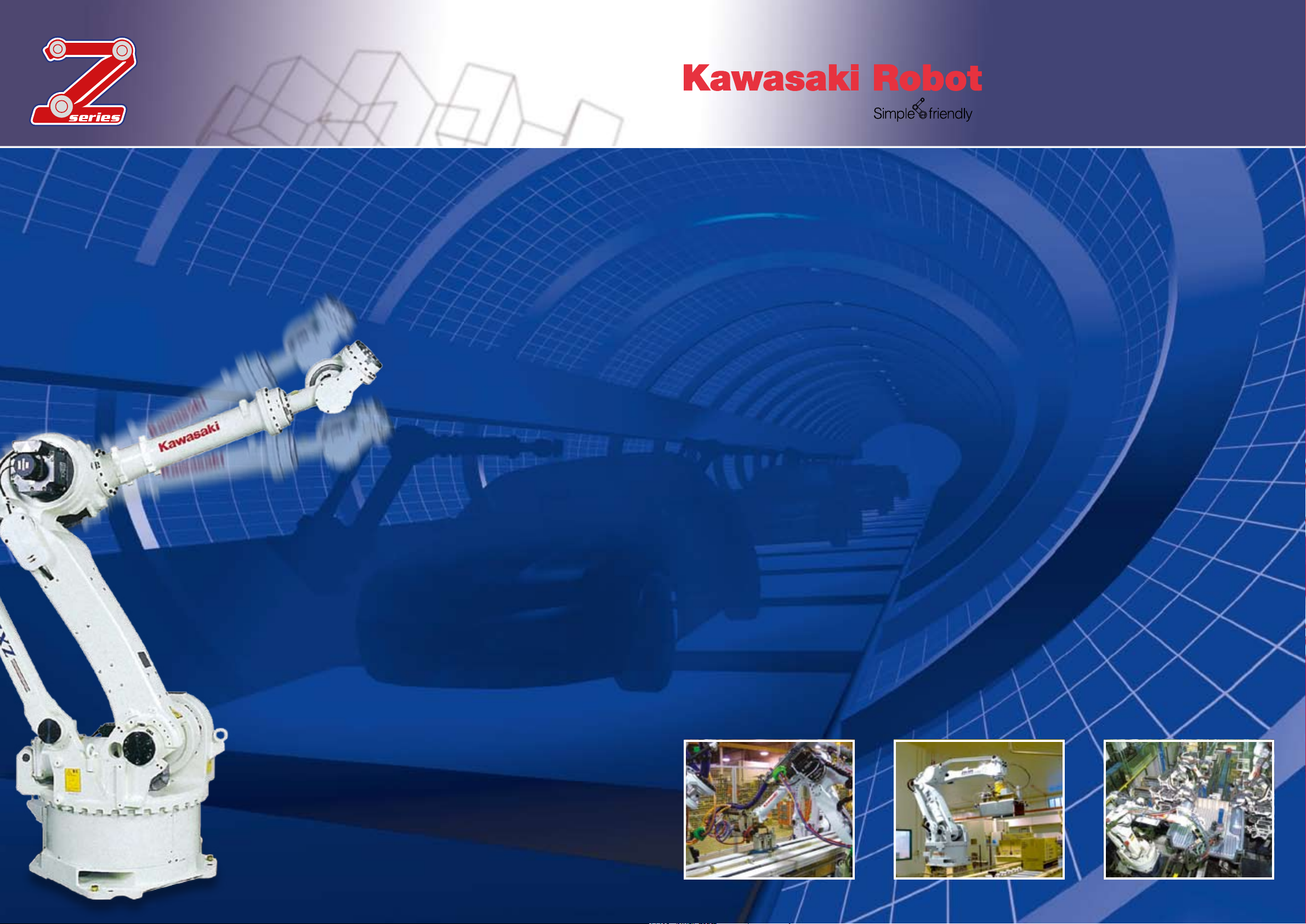
The Kawasaki Z-Series high performance robots provide
exibility as well as the ability, at high payloads and long
reach, to suit all applications, including welding, handling,
tending and much more. With twelve different versions,
divided into three distinct design groups the Z-series can
provide the right model for all future applications.
Whether it‘s the “ZX” for oor mounting, the “ZT” for shelf
mounting or the “ZB” as a compact arm, the Z-series can
do it all. All Z-Series robots are powered by the D-Controller,
exible Controller Unit.
Protective congurations IP65, IP67
Protection class IP65 applies for the robot arm and IP67 for the wrist part. This means that the
Z Series can be used without problems in rough working environments.
Convertability
Simple hardware and software modications allow an optimisation of the ZX165U in terms of reach or
payload. A subsequent adjustment of the robot to different tasks poses no problems and can be car-
ried out at low cost
Spot welding Palletizing Spot welding
Page 3

Specifications Specifications
TYP
Type of arm
Degrees of freedom
Reach
Maximum Payload
JT1
JT2
JT3
Maximum
JT4
stroke
JT5
JT6
JT7
JT1
JT2
JT3
Maximum
JT4
speed
JT5
JT6
JT7
Repeatability
JT4
Moment*
JT5
JT6
JT4
Moment
JT5
of inertia
JT6
Weight
Recommended Controller
Installation
Integrated functions
Optional
Colour
ZB150S ZT130L ZT130U ZT165U ZT200UZB100L
1,655 mm
100 kg
± 160°
+120°~-70°
+100°~-150°
± 360°
± 130°
± 360°
standard 2,000 mm
100°/s
100°/s
90°/s
135°/s
135°/s
210°/s
1,000 mm/s
0 N·m
0 N·m
0 N·m
78.4 kg/m²
78.4 kg/m²
40.18 kg/m²
915 kg
1,500 mm/s
Air Line (12 mm Ø)
Mechanical stopper JT1/JT2/JT3,
special colour.
1,365 mm
150 kg
± 160°
+120°~-70°
+100°~-150°
± 360°
± 130°
± 360°
standard 2,000 mm
100°/s
100°/s
90°/s
135°/s
135°/s
210°/s
1,000 mm/s
911.4 N·m
911.4 N·m
450.8 N·m
78.4 kg/m²
78.4 kg/m²
40.18 kg/m²
900 kg
1,500 mm/s
ZX130U ZX165L ZX165U ZX200U ZX300SZX130L
Articulated arm
6 axes (optional 7 axes)
3,530 mm
130 kg
± 180°
+60°~-75°
+165°~-95°
± 360°
± 130°
± 360°
standard 2,000 mm
105°/s
105°/s
105°/s
140°/s
135°/s
230°/s
1,000 mm/s
735 N·m
735 N·m
421 N·m
51.9 kg/m²
51.9 kg/m²
27.4 kg/m²
1,565 kg
2,500 mm/s
Air lines (12 mm Ø x 2), wiring for the solenoid valves of the grab (A.C. 24V)
Mechanical stopper JT1/JT2/JT3, special colour, internal wiring for end effector,
twin solenoid valve 1/2, single solenoid valve 1/2, twin solenoid valve 1 + single
solenoid valve 1, 1 lter control unit, internal hoses for welding gun cooling water
Munsell 10GY9/1 or equivalent Munsell 10GY9/1 or equivalent
± 0,3mm
3,230 mm
130 kg
± 180°
+60°~-75°
+165°~-95°
± 360°
± 130°
± 360°
standard 2,000 mm
105°/s
105°/s
105°/s
140°/s
135°/s
230°/s
1,000 mm/s
735 N·m
735 N·m
421,4 N·m
51.9 kg/m²
51.9 kg/m²
27.44 kg/m²
1,550 kg
2,500 mm/s
D42
Floor
3,230 mm
165 kg
± 180°
+60°~-75°
+165°~-95°
± 360°
± 130°
± 360°
standard 2,000 mm
105°/s
105°/s
105°/s
135°/s
135°/s
210°/s
1,000 mm/s
911,4 N·m
911,4 N·m
450,8 N·m
78.4 kg/m²
78.4 kg/m²
40.18 kg/m²
1,550 kg
2,500 mm/s
3,230 mm
200 kg
± 180°
+60°~-75°
+165°~-95°
± 360°
± 130°
± 360°
standard 2,000 mm
90°/s
90°/s
90°/s
120°/s
115°/s
180°/s
1,000 mm/s
980 N·m
980 N·m
490 N·m
93.1 kg/m²
93.1 kg/m²
46.1 kg/m²
1,550 kg
2,500 mm/s
2,951 mm
130 kg
± 180°
+75°~-60°
+250°~-120°
± 360°
± 130°
± 360°
standard 2,000 mm
110°/s
110°/s
110°/s
140°/s
135°/s
230°/s
1,000 mm/s
7.35 N·m
7.35 N·m
221.4 N·m
51.94 kg/m²
51.94 kg/m²
27.44 kg/m²
1,400 kg
2,500 mm/s
twin solenoid valve 1/2, single solenoid valve 1/2, twin solenoid valve 1 + single solenoid valve 1,
2,651 mm
130 kg
± 180°
+75°~-60°
+250°~-120°
± 360°
± 130°
± 360°
standard 2,000 mm
110°/s
110°/s
110°/s
140°/s
135°/s
230°/s
1,000 mm/s
7.35 N·m
7.35 N·m
221.4 N·m
51.94 kg/m²
51.94 kg/m²
27.44 kg/m²
1,350 kg
2,500 mm/s
Air lines (12 mm Ø x 2), wiring for the solenoid valves of the grab (A.C. 24V)
Mechanical stopper JT1/JT2/JT3, special colour, internal wiring for end effector,
1 lter control unit, internal hoses for welding gun cooling water
+250°~-120°
standard 2,000 mm
1,000 mm/s
40.18 kg/m²
2,500 mm/s
Articulated arm
6 axes (optional 7 axes)
2,810 mm
165 kg
± 180°
+75°~-60°
± 360°
± 130°
± 360°
standard 2,000 mm
100°/s
105°/s
95°/s
135°/s
135°/s
210°/s
911.4 N·m
911.4 N·m
450.8 N·m
78.4 kg/m²
78.4 kg/m²
1,355 kg
D42
Floor
2,651 mm
165 kg
± 180°
+75°~-60°
+250°~-120°
± 360°
± 130°
± 360°
110°/s
110°/s
110°/s
135°/s
135°/s
210°/s
1,000 mm/s
911.4 N·m
911.4 N·m
450.8 N·m
78.4 kg/m²
78.4 kg/m²
40.18 kg/m²
1,355 kg
2,500 mm/s
2,651 mm
200 kg
± 180°
+75°~-60°
+250°~-120°
± 360°
± 130°
± 360°
standard 2,000 mm
95°/s
95°/s
95°/s
120°/s
115°/s
180°/s
1,000 mm/s
± 0,3mm
980 N·m
980 N·m
490 N·m
93.1 kg/m²
93.1 kg/m²
46.1 kg/m²
1,350 kg
2,500 mm/s
2,501 mm
300 kg
± 180°
+75°~-60°
+250°~-120°
± 360°
± 120°
± 360°
standard 2,000 mm
100°/s
85°/s
85°/s
90°/s
90°/s
150°/s
1,000 mm/s
1,715 N·m
1,715 N·m
862.4 N·m
166.6 kg/m²
166.6 kg/m²
107.8 kg/m²
1,400 kg
2,500 mm/s
Type of arm
Degrees of freedom
Reach
Maximum Payload
JT1
JT2
JT3
JT4
JT5
JT6
JT7
JT1
JT2
JT3
JT4
JT5
JT6
JT7
Repeatability
JT4
JT5
JT6
JT4
JT5
JT6
Weight
Recommended Controller
Installation
Integrated functions
Optional
Colour
TYP
Maximum
stroke
Maximum
Speed
Moment*
Moment
of inertia
ZT130LZB150S ZX300SZX130U
ZT130U
ZT165U
ZT200U
ZX130LZB100L
ZX165U
ZX200U
Page 4

Motion Range & DimensionsMotion Range & Dimensions
:Unnecessary
to tighten bolts
Ø0.04
X
YXØ0.15
Y
X
ISO FLANGE
OPTION FLANGE
* Dimension:228
X YØ0.15
Ø0.04
X
Y
X
* Dimension:244
A
VIEW
Ø9H7 Depth12
6–M10 Depth 16
60
°
30
°
Ø160
Ø55H7
Depth 12
Ø9
2
30
°
30
°
Ø160
6–M10 Depth 12
2–Ø10H7 Depth 12
Ø80H7
Depth 8
Ø125
JT5±130°
JT6±360°
JT4±360°
A
JT1
JT3
JT1
JT3
JT3
JT2
JT2
Point P
Working range
based on point P
Point P
100
°
150
°
300
410
50 50
5050
700
25
650
25
700
6557065
4-Ø22
4-Ø40
23
427
195
1,315
565
474
545
565
545
*
850 250
70
°
120
°
150
°
160
°
160
°
587.5 1,960
2,547.5
1,665 1,131
957 708
329
Installations Dinensions
:Unnecessary
to tighten bolts
Ø0.04 X
YXØ0.15
Y
X
ISO FLANGE
OPTION FLANGE
* Dimension:228
X YØ0.15
Ø0.04
X
Y
X
* Dimension:244
A
VIEW
Ø9H7
+0.015
0
Depth 12
6-M10 Depth 16
60
°
30
°
Ø160
Ø55H7
+0.030
0
Depth 12
Ø9
2
30
°
30
°
Ø160
6–M10 Depth 12
2-Ø10H7
+0.015
0
Depth 12
Ø80H7
+0.030
0
Depth 8
Ø125
* TOOL, HAND, etc. may interfere
with robot arm depending on
angle of wrist axes.
JT5±130°
JT6±360°
JT4±360°
A
JT1
JT3
JT1
JT3
JT3
JT2
JT2
Installation Dimensions
Point P
Working range
based on point P
Point P
100
°
150
°
300
410
50 50
5050
700
25 650 25
700
6557065
4–Ø22
4-Ø40
467
23
427
195
1,315
565
287.5
474
539
216
1,947.5
1,115832.5
8311,365
545
565
545
*
550 250
7
0°
120
°
150
°
826
160
°
160
°
Ø0.05
JT1 180°
JT1 180°
A
JT3
JT3
JT2
JT2
JT4±360°
JT6±360°
JT5±130°
B
370
75
125
125
125
500100 100
500 100
100
770
770
125
2–Ø25G8
300
300300
8–Ø22
30
173.05
4,571
530
1,100
300
600
78 1,300
2,103
80
3,230
24.40600.5210
00
9090
80
58
95
°
16
5
°
60
°
75
°
24.401,300
395510150
1.30
90
142
5 x 2–M10–20/25
10 x 2–M6–12/18
Y
X
Ø0.04
X
Ø0.15
YX
Depth 8
Ø1
2
5
2–Ø10H7
+0.015
0
Depth 12
6–M10 Depth 12
Ø1
60
30
°
30
°
Unnecessary
for standard spec.
Ø80H7
+0.030
0
• ISO 9409-1 Series 2 (Ø125)
for 130S/165U
JT3
JT2
JT3
JT2
JT4±360˚
JT6±360˚
JT5±130˚
JT1
JT1
A
288
60
˚
75
˚
70
˚
120
˚
3,340
3,415
1,965 2,651
1,490
1,225
670 1,100 270
1,300 244
395510150
13
90
142
370
75
125
125 125
500 100100
500 100
2–Ø25G8
Ø0.05
100
770
770
125
300
Installation Dimensions
300 300
9090
80
58
8–Ø22
R517
180
˚
180
˚
R1,289
1,199
600.5210
30
Y
X
X
YX
ISO FLANGE
30
˚
30
˚
5 x 2–M10–20/25
10 x 2–M6–12/18
6–M10 Depth 12
Ø0.15
Ø
160
Ø
12
5
Ø0.04
2
–Ø10H7
Depth 12
Ø80H7
Depth 8
* Dimension:228
ZB100L
ZT130U
ZT165U
ZT200U
ZB150S
ZX130U
ZX165U
ZX200U
Page 5

Motion Range & DimensionsMotion Range & Dimensions
Unnecessary
to tighten bolts
YX
Ø0.15
Y
X
ISO FLANGE
OPTION FLANGE
*Dimension:228
X Y
Ø0.15
Ø0.04
X
Y
X
* Dimension:244
Ø0.04
X
VIEW A
2–Ø9H7
Depth 12
6–M10 Depth 16
60
°
30
°
Ø160
Ø55H7
Depth 12
Ø92
30
°
30
°
Ø160
6–M10 Depth 12
2–Ø10H7
Depth 12
Ø80H7
Depth 8
Ø
125
JT3
JT2
JT3
JT2
Ø0.05
JT4±360°
JT6±360°
JT5±130°
JT1
JT1
A
Inter feren ce rad ius a round
the r otati onal a xis
Rear side
Interference area
Installation Dimensions
Point P
Point P
Work ing r ange
base d on point P
ISO FLANGE
OPTION FLANGE
* Dimension
228
244
8–Ø22
30
*
288
60
°
75
°
70
°
120
°
1,490
1,459
270
1,100
670
395669
150
13
90
142
370
75
125
125 125
500
100100
500
100100
770
770
125
2–Ø25G8
300
300 300
10 x 2–M6–12/18
5 x 2–M10–20/25
9090
80
58
R517
180°
180°
LINK H
1,199
R1,289
600.5
210
3,499
3,733
1,225
2,124
2,810
LINK H
Ø0.05
JT4±360°
JT6±360°
JT5±120°
JT1 180°
JT1
Int erf ere nc e r adi us ar oun d
the ro tat io nal ax is
A
JT2
JT3
JT2
JT3
1,150 248
395360150
13
90
142
370
75
125
125 125
500 100100
500 100100
770
770
125
2–Ø25G8
300
300 300
9090
80
58
5 x 2–M10–20/25
10 x 2–M6–12/18
8–Ø22
R
5
1
7
Link H
Link H
1,199
30
288
250.05
3,190
1,490
1,225
70
°
1
2
0
°
75
°
6
0
°
1,815
3,115
2701,100670
600.5210
R1,289
Rear side interference area
X
Ø0.15
X
Ø0.04
XYY
Depth 8
X
Ø0.15
Ø0.04
XYY
X
• Conventional Type (Ø113)
Unnecessary
for standard spec.
VIEW A
6–M10 Depth 12
3
0
°
3
0
°
Ø160
2–Ø10H7
+0.015
0
Depth 12
• ISO 9409-1 Series 1 (Ø160)
+0.035
0
Ø100H7
Ø2
0
0
10–M10 Depth 17
3
0
°
3
0°
2–Ø10H7
+0.015
0
Depth 17
Ø2
0
0
Ø1
1
3
Depth 12
+0.030
0
Ø68H7
180°
Dimensions for Base
JT3
JT2
JT3
JT2
Ø0.05
JT4±360°
JT6±360°
JT5±130°
Dimensions for Base
JT1
180°
A
288
6
0
°
75
°
7
0
°
1
2
0
°
1,490
670 1,100 270
1,600
695510150
13
90
142
370
75
125
125 125
500 100100
500 100100
770
770
125
2–Ø25G8
300
300 300
9090
80
58
5 x 2–M10–20/25
10 x 2–M6–12/18
8–Ø22
R
5
1
7
180
°
Link H
Link H
R1,289
1,199
Rear side interference area
600.5210
30
3,640
4,015
2,951
1,225
2,265
Y
X
Ø0.04
X
Ø0.15
YX
Depth 8
X
Depth 12
Y
Ø0.15
YX
X
Ø0.04
Y
Ø1
2
5
2–Ø10H7
+0.015
0
Depth 12
6–M10 Depth 12
Ø1
6
0
30
°
30
°
Ø9
2
+0.030
0
Ø55H7
Ø
16
0
30
°
6
0
°
6–M10 Depth 16
Ø9H7
+0.015
0
Depth 12
Interference radius around
the rotational axis
JT1
Ø80H7
• ISO 9409-1 Series 2 (Ø125)
Unnecessary
for standard spec.
• Conventional Type (Ø92)
ZX130L
ZX300S
ZX165L
Page 6

Controller
‚q‚d‚o‚d‚`‚s‚s‚d‚`‚b‚g
‚d‚q‚q‚n‚q
?@‚o‚n‚v‚d‚q
‚b‚n‚m‚s‚q‚n‚k
SIDE VIEW
FRONT VIEW
SIDE VIEW
REAR VIEW
1,200
550
600
470
160
‚q‚t‚m
‚b‚x‚b‚k‚d
‚r‚s‚`‚q‚s
‚g‚n‚k‚c
‚l‚n‚s‚n‚q
‚o‚n‚v‚d‚q
‚q‚d‚r‚d‚s
‚d‚q‚q‚n‚q
Ergonomic operation
• Optimised work at the teach pendant
The Teach Pendant (TP) is a combination of control
keyboard and an easy-read, 6.4 inch colour LCD touchscreen. A new hardware structure for the TP reduces the
key response time and the ergonomic arrangement of
the keys helps the operator achieve optimised inputs and
programming. The workow is optimised and the TP becomes an ergonomic user platform for operating the robot.
Special software
combined with standards
Applications Software Modules facilitate programming for
a wide range of applications such as palletizing, handling,
spot welding, bonding and arc welding. The simplied
block programming and Kawasaki‘s high level robot
language (AS-language) provide enormous possibilities
for innovative movement- and process control. Using the
available options – such as servo-welding, network support and a high-performance visualisation system –
a platform is created to nd exible solutions for even
the most complex of applications.
High performance through
modern control technology
A RISC, 64-bit high-speed dual processor provides the
computing power. The use of a fully digitally controlled
servo-system has signicantly improved operating performance, cycle time and path accuracy. In addition, system
errors have been reduced to a minimum through collision
detection/automatic stop and path recovery after an emergency stop.
The controller is of course fully downwardly compatible.
This means that the D controller can be integrated in existing old systems with no problems.
Teach Pendant
• Large LCD colour monitor with
touchscreen functions.
• Ergonomically arranged cursor keys.
• The key layout has been optimised
with respect to the frequency of use
by the operator.
Modular and
exible control design
• Connection of peripheral equipment
Standard I/O connections and a number of eld bus interfaces such as Interbus, Probus, CC-Link and DeviceNet
etc. are available as interfaces to the peripheral equipment. The peripheral equipment is connected directly
and permits the system‘s high exibility.
Furthermore, K-Logic (integrated software PLC) allows
the creation of a highly complex Integrated system at a
minimum cost
• Network communication
The controller also supports network communication via
Ethernet to communicate with a host computer and for
an easy upload and download of the programs to be run.
Furthermore, the status of the robot can be monitored
per remote access via an Intranet/Internet connection.
• Extension with aditional axes
A further two axes can be integrated in the standard
controller without any problems and without an additional housing. Three or more additional axes are available
by selecting SSCNET-compatible motors. This allows
multi-axial systems to be easily congured to match the
customer‘s requirements.
User-friendly design
A reduction of the robot‘s internal wiring and the use of
modular assemblies facilitates servicing and ensures
shorter working times when repairing or replacing parts
with no long and costly downtimes.
What‘s more, supporting service functions
such as data storage help the user locate
the causes of existing problems. The
service software includes restoration
procedures* in the event of system
errors (Z Series) and an Ethernet
interface allows a remote system
diagnosis.
* In the event of system er rors th e serv ice and su ppor t
function of t he Z Seri es offe rs proc edures t o display:
possible so urces of error s and probabiliti es as well
as diagnosis , replac ement instructions and t imes to
remedy faults.
Specifications
MODEL
Design
Number of controlled axes
Servomotor
Position detection
Drive system
Programming
Coordinates Systems
Types of motion control
Ext. control signals
Multi-
purpose
Input signals
signals
Output signals
Storage capacity
External memory
PC, network, etc.
Data com-
munication
Field bus
interface
Teach pendant
Control panel
Teach Pendant
Cable
length
Robot controller
Dimensions (WxDxH)
Weight
Necessary
power supply
Own earthing of the robot
temperature/humidity
Colour
*
¹ Please c ontact us if you use 7 a xes or mor e.
teach lock switch, deadman‘s switch, 58 hardware keys
(keys for manual operation of the robot, cursor keys, etc.)
Basic switch: motor voltage on, cycle star t, error reset,
0-45° C, 35-85% humidity without dew formation and frost
External View & Dimensions
D42
Fully digitally controlled servo -system
Movement with axis, linear and circle interpolation
1 MB: approx. 10,000 program steps
6.4 “ TFT LCD touchscreen, 640x480 VGA, “E-Stop”,
“E-Stop”, run/hold, teach/repeat, etc.
A.C. 380/400/415/440/460/480 V ± 10%,
< 100 Ω; maximum leakage current 100 mA
STANDARD
Standalone main housing
6 axes
A.C. servomotor
Absolute encoder
Block teaching or AS language
Axis, basis, tool
Motor voltage Off, Hold
32 channels
32 channels
PCMCIA card slot
RS232C, Ethernet
10 m
10 m
600 mm x 550 mm x 1,200 mm
130 kg
50/60 Hz, 3 phases, 11,4 KVA
Munsell 10GY9/1 or equivalent
D 42
OPTION
Maximum 16 axes*¹
Fixed tool point
64/96/128 channels
64/96/128 channels
2/4/8 MB: approx. 20,000/40,000/80,000 program steps
RS485
CC-Link, DeviceNet, Probus-DP,
ControlNET, AB Remote I/O, Interbus
5 m, 15 m, 20 m, 25 m, 30 m
5 m, 15 m, 20 m, 25 m, 30 m, 35 m, 40 m
approx. 200 kg (with transformer)
A.C. 200/220 V ± 10%,
50/60 Hz, 3 phases, 11,4 KVA
< 100 Ω; max. leakage current 100 mA (with transformer)
• Deadman‘s switch with three positions
on rear.
 Loading...