


Kawasaki Z750S, Z750S 2005, Z750 2005 Service Manual
Z750S
Motorcycle
Service Manual

Quick Reference Guide
General Information 1 j
Periodic Maintenance 2 j
Fuel System (DFI) 3 j
Cooling System 4 j
Engine Top End 5 j
Clutch 6 j
Engine Lubrication System 7 j
Engine Removal/Installation 8 j
Crankshaft/Transmission 9 j
This quick reference guide will assist
you in locating a desired topic or procedure.
•Bend the pages back to match the
black tab of the desired chapter number with the black tab on the edge at
each table of contents page.
•Refer to the sectional table of contents
for the exact pages to locate the specific topic required.
Wheels/Tires 10 j
Final Drive 11 j
Brakes 12 j
Suspension 13 j
Steering 14 j
Frame 15 j
Electrical System 16 j
Appendix 17 j


Z750S
Motorcycle
Service Manual
All rights reserved. No parts of this publication may be reproduced, stored in a retrieval system, or
transmitted in any form or by any means, electronic mechanical photocopying, recording or otherwise,
without the prior written permission of Quality Division/Consumer Products & Machinery Company/Kawasaki
Heavy Industries, Ltd., Japan.
No liability can be accepted for any inaccuracies or omissions in this publication, although every possible
care has been taken to make it as complete and accurate as possible.
The right is reserved to make changes at any time without prior notice and without incurring an obligation
to make such changes to products manufactured previously. See your Motorcycle dealer for the latest
information on product improvements incorporated after this publication.
All information contained in this publication is based on the latest product information available at the time
of publication. Illustrations and photographs in this publication are intended for reference use only and may
not depict actual model component parts.
© 2004 Kawasaki Heavy Industries, Ltd. First Edition (1) : Nov. 8, 2004 (M)

LIST OF ABBREVIATIONS
A ampere(s) lb pound(s)
ABDC after bottom dead center m meter(s)
AC alternating current min minute(s)
ATDC after top dead center N newton(s)
BBDC before bottom dead center Pa pascal(s)
BDC
BTDC before top dead center
°C degree(s) Celsius
DC direct current rpm revolution(s) per minute
F farad(s) TDC top dead center
°F degree(s) Fahrenheit TIR total indicator reading
ft foot, feet V volt(s)
g gram(s) W watt(s)
h hour(s) Ω ohm(s)
L liter(s)
bottom dead center
PS
psi
r revolution
horsepower
pound(s) per square inch
Read OWNER’S MANUAL before operating.

EMISSION CONTROL INFORMATION
To protect the environment in which we all live, K awasaki has incorporated crankcase emission (1) and exhaust emission (2) control systems in compliance with applicable regulations of
the United States Environmental Protection Agency and California Air Resources Board. Additionally, Kawasaki has incorporated an evaporative emission control system (3) in compliance
with applicable regulations of the California Air Resources Board on vehicles sold in California
only.
1. Crankcase Emission Control System
This system eliminates the release of crankcase vapors into the atmosphere. Instead, the vapors
are routed through an oil separator to the intake side of the engine. While the engine is operating,
the vapors are drawn into combustion chamber, where they are burned along with the fuel and air
supplied by the fuel injection system.
2. Exhaust Emission Control System
This system reduces the amount of pollutants discharged into the atmosphere by the exhaust
of this motorcycle. The fuel, ignition, and exhaust systems of this motorcycle have been carefully
designed and constructed to ensure an efficient engine with low exhaust pollutant levels.
The exhaust system of this model motorcycle manufactured primarily for sale in California includes
a catalytic converter system.
3. Evaporative Emission Control System
Vapors caused by fuel evaporation in the fuel system are not vented into the atmosphere. In-
stead, fuel vapors are routed into the running engine to be burned, or stored in a canister when
the engine is stopped. Liquid fuel is caught by a vapor separator and returned to the fuel tank.
The Clean Air Act, which is the Federal law covering motor vehicle pollution, contains what is
commonly referred to as the Act’s "tampering provisions."
"Sec. 203(a) The following acts and the causing thereof are prohibited...
(3)(A) for any person to remove or render inoperative any device or element of design installed
on or in a motor vehicle or m otor vehicle engine in compliance with regulations under this
title prior to its sale and delivery to the ultimate purchaser, or for any manufacturer or dealer
knowingly to remove or render inoperative any such device or element of design after such
sale and delivery to the ultimate purchaser.
(3)(B) for any person engaged in the business of repairing, servicing, selling, leasing, or trading
motor v ehicles or motor vehicle engines, or who operates a fleet of motor vehicles knowingly to remove o r render inoperative any device or element of design installed on or in a
motor vehicle or motor vehicle engine in compliance with regulations under this title following its sale and delivery to the ultimate purchaser..."
The phrase "remove or render inoperative any device or element of design" has been generally
○
interpreted as follows:
1. Tampering does not in clude the temporary removal or rendering inoperative of devices or elements of design in order to perform maintenance.
2. Tampering could include:
a.Maladjustment of vehicle components such t hat the emission standards are ex-
ceeded.
b.Use of replacement parts or accessories which adversely affect the performance
or durability of the motorcycle.
c.Addition of components or accessories that result in the vehicle exceeding the stan-
dards.
d.Permanently removing, disconnecting, or rendering inoperative any component or
element of design of the emission control systems.
WE RECOMMEND THAT ALL DEALERS OBSERVE THESE PROVISIONS OF FEDERAL
LAW, THE VIOLATION OF WHICH IS PUNISHABLE BY CIVIL PENALTIES NOT
EXCEEDING $10,000 PER VIOLATION.
NOTE

TAMPERING WITH NOISE CONTROL SYSTEM PROHIBITED
Federal law prohibits the following acts or the causing thereof: (1) The removal or rendering
inoperative by any person other than for purposes of maintenance, repair, or replacement, of any
device o r element of design incorporated into any new vehicle for the purpose of noise control
prior to its sale or delivery to the ultimate purchaser or while it is in use, or (2) the use of the
vehicle after such device or element of design has been removed or rendered inoperative by
any person.
Among those acts presumed to constitute tampering are the acts listed below:
Replacement of the original exhaust system or muffler with a component not in compliance
•
with Federal regulations.
Removal of the muffler(s) or any internal portion of the muffler(s).
•
Removal of the air box or air box cover.
•
Modifications to the muffler(s) or air inlet system by cutting, drilling, or other means if such
•
modifications result in increased noise levels.
Foreword
This manual is designed primarily for use by
trained mechanics in a properly equipped shop.
However, it contains enough detail and basic information to make it useful to the owner who desires to perform his own basic maintenance and
repair work. A basic knowledge of mechanics,
the proper use of tools, and workshop procedures must be understood in order to carry out
maintenance and repair satisfactorily. Whenever the owner has insufficient experience or
doubts his ability to do the work, all adjustments, maintenance, and repair should be carried out only by qualified mechanics.
In order to perform the work efficiently and
to avoid costly mistakes, read the text, thoroughly familiarize yourself with the procedures
before starting work, and then do the work carefully in a c lean area. Whenever special tools or
equipment are specified, do not use makeshift
tools or equipment. Precision measurements
can only be made if the proper instruments are
used, and the use of substitute tools may adversely affect safe operation.
For the duration of the warranty period,
we recommend that all repairs and scheduled
maintenance be performed in accordance with
this service manual. Any owner maintenance or
repair procedure not performed in accordance
with this manual may void the warranty.
To get the longest life out of your vehicle:
Follow the Periodic Maintenance Chart in the
•
Service Manual.
Be alert for problems and non-scheduled
•
maintenance.
Use proper tools and genuine Kawasaki Mo-
•
torcycle parts. Special tools, gauges, and
testers that are necessary when servicing
Kawasaki motorcycles are introduced by the
Special Tool Catalog or Manual. Genuine
parts provided as spare parts are listed in the
Parts Catalog.
Follow the procedures in this manual care-
•
fully. Don’t take shortcuts.
Remember to keep complete records of main-
•
tenance and repair with dates and any new
parts installed.
How to Use This Manual
In preparing this manual, we divided the product into its major systems. These systems became the manual’s chapters. All information
for a particular system from adjustment through
disassembly and inspection is located in a single chapter.
The Quick Reference Guide shows you all
of the product’s system and assists in locating
their chapters. Each chapter in turn has its own
comprehensive Table of Contents.
The Periodic Maintenance Chart is located in
the Periodic Maintenance chapter. The chart
gives a time schedule for required maintenance
operations.
If you want spark plug information, for example, go to the Periodic Maintenance Chart first.
The chart tells you how frequently to clean and
gap the plug. Next, use the Quick Reference
Guide to locate the Periodic Maintenance chapter. Then, use the Table of Contents on the first
page of the chapter to find the Spark Plug section.
Whenever you see these WARNING and
CAUTION symbols, heed their instructions!
Always follow safe operating and maintenance
practices.
WARNING
This warning symbol identifies special
instructions or procedures which, if not
correctly followed, could result in per-
sonal injury, or loss of life.
CAUTION
This caution symbol identifies special
instructions or procedures which, if not
strictly observed, could result in dam-
age to or destruction of equipment.
This manual contains four more symbols (in
addition to WARNING and CAUTION) which will
help you distinguish different types of information.

NOTE
This note symbol indicates points of par-
○
ticular interest for more efficient and convenient operation.
Indicates a procedural step or work to be
•
done.
Indicates a procedural sub-step or how to do
○
the work of the procedural step it follows. It
also precedes the text of a NOTE.
Indicates a conditional step or what action to
take based on the results of the test or inspection in the procedural step or sub-step it fol-
lows.
In most chapters an exploded view illustration
of the system components follows the Table of
Contents. In these illustrations you will find the
instructions indicating which parts require specified tightening torque, oil, grease or a locking
agent during assembly.

GENERAL INFORMATION 1-1
General Information
Table of Contents
Before Servicing ..................................................................................................................... 1-2
Model Identification................................................................................................................. 1-7
General Specifications............................................................................................................ 1-9
Technical Information - Air Inlet System ................................................................................. 1-12
Technical Information - New Ignition Interlock Side Stand ..................................................... 1-14
Technical Information - Tail/Brake Lights Employing LED ...................................................... 1-15
Technical Information - KAWASAKI LOW EXHAUST EMISSION SYSTEM .......................... 1-17
Technical Information - Immobilizer System (Equipped Models) ............................................ 1-18
Unit Conversion Table ............................................................................................................ 1-21
1
1-2 GENERAL INFORMATION
Before Servicing
Before starting to perform an inspection service or carry out a disassembly and reassembly operation on a motorcycle, read the precautions given below. To facilitate actual operations, notes, illustrations, photographs, cautions, and detailed descriptions have been included in each chapter wherever
necessary. This section explains the items that require particular attention during the removal and
reinstallation or disassembly and reassembly of general parts.
Especially note the following:
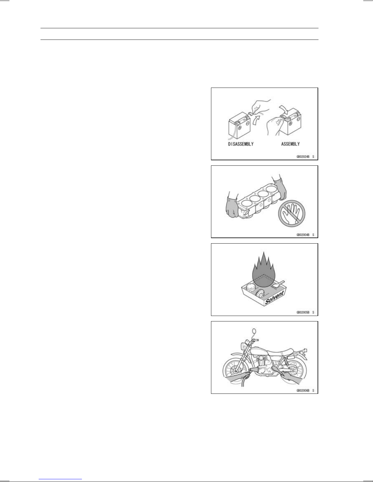
Battery Ground
Before completing any service on the motorcycle, disconnect the battery wires from the battery to prevent the engine
from accidentally turning over. Disconnect the ground wire
(–) first and then the positive (+). When completed with the
service, first connect the positive (+) wire to the positive (+)
terminal of the battery then the negative (–) wire to the negative terminal.
Edges of Parts
Lift large or heavy parts wearing gloves to prevent injury
from possible sharp edges on the parts.
Solvent
Use a high-flush point solvent when cleaning parts. High
-flush point solvent should be used according to directions
of the solvent manufacturer.
Cleaning vehicle before disassembly
Clean the vehicle thoroughly before disassembly. Dirt or
other foreign materials entering into sealed areas during vehicle disassembly can cause excessive wear and decrease
performance of the vehicle.
Before Servicing
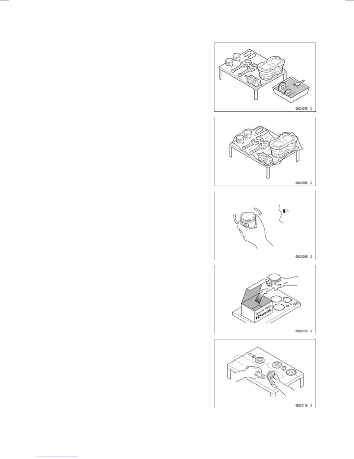
Arrangement and Cleaning of Removed Parts
Disassembled parts are easy to confuse. Arrange the
parts according to the order the parts were disassembled
and clean the parts in order prior to assembly.
Storage of Removed Parts
After all the parts including subassembly parts have been
cleaned, store the parts in a clean area. Put a clean cloth
or plastic sheet over the parts to protect from any foreign
materials that may collect before re-assembly.
GENERAL INFORMATION 1-3
Inspection
Reuse of worn or damaged parts may lead to serious accident. Visually inspect removed parts for corrosion, discoloration, or other damage. Refer to the appropriate sections
of this manual for service limits on individual parts. Replace
the parts if any damage has been found or if the part is beyond its service limit.
Replacement Parts
Replacement parts must be KAWASAKI genuine or
recommended by KAWASAKI. Gaskets, O-rings, oil seals,
grease seals, circlips or cotter pins must be replaced with
new ones whenever disassembled.
Assembly Order
In most cases assembly order is the reverse of disassembly, however, if assembly order is provided in this Service
Manual, follow the procedures given.
1-4 GENERAL INFORMATION
Before Servicing
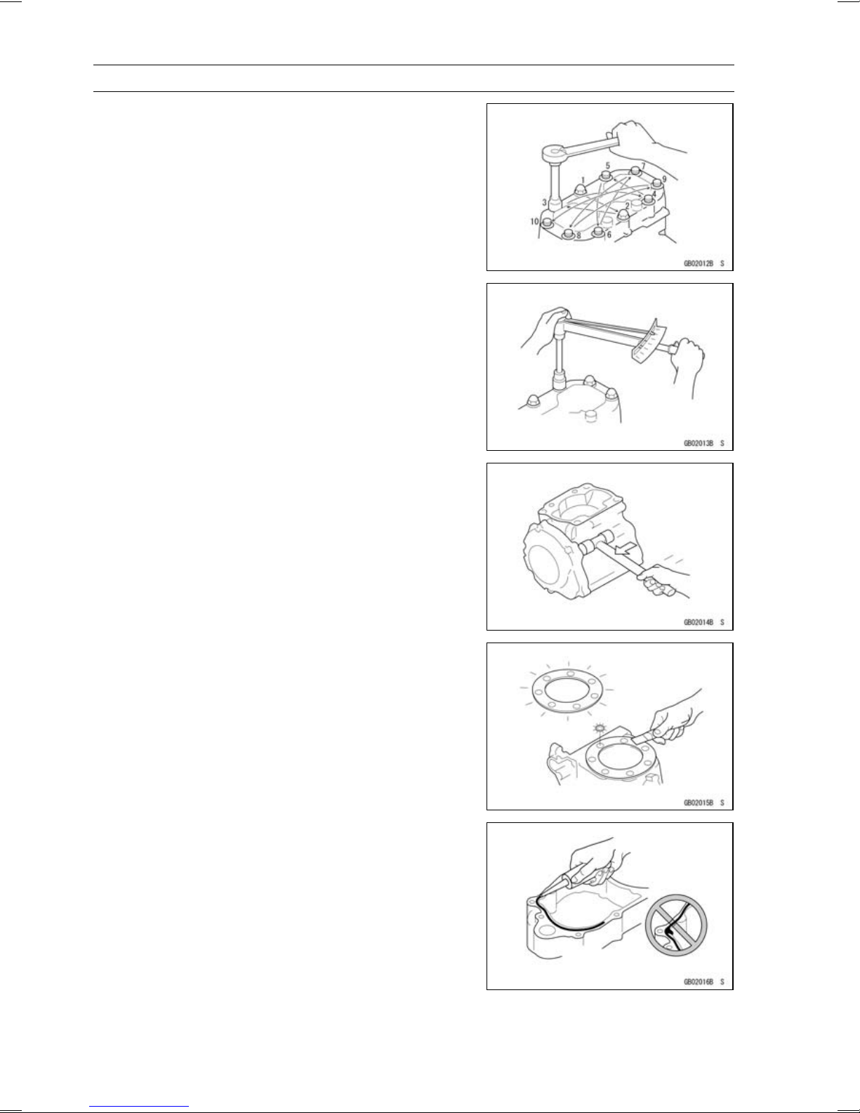
Tightening Sequence
Generally, when installing a part with several bolts, nuts,
or screws, start them all in their holes and tighten them to
a snug fit. Then tighten them according to the specified sequence to prevent case warpage or deformation which can
lead to malfunction. Conversely when loosening the bolts,
nuts, or screws, first loosen all of them by about a quarter turn and then remove them. If the specified tightening
sequence is not indicated, tighten the fasteners a lternating
diagonally.
Tightening Torque
Incorrect torque applied to a bolt, nut, or screw may
lead to serious damage. Tighten fasteners to the specified
torque using a good quality torque wrench. Often, the
tightening sequence is followed twice-initial tightening and
final tightening with torque wrench.
Force
Use common sense during disassembly and assembly,
excessive force can cause expensive or hard to repair damage. When necessary, remove screws that have a non
-permanent locking agent applied using an impact driver.
Use a plastic-faced mallet whenever tapping is necessary.
Gasket, O-ring
Hardening, shrinkage, or damage of both gaskets
and O-rings after disassembly can reduce sealing performance. Remove old gaskets and clean the sealing
surfaces thoroughly so that no gasket material or other
material remains. Install new gaskets and replace used
O-rings when re-assembling
Liquid G asket, Non-permanent Locking Agent
For applications that require Liquid Gasket or a
Non-permanent Locking Agent, clean the surfaces so
that no oil residue remains before applying liquid gasket or
non-permanent locking agent. Do not apply them excessively. Excessive application can clog oil passages and
cause serious damage.
Before Servicing
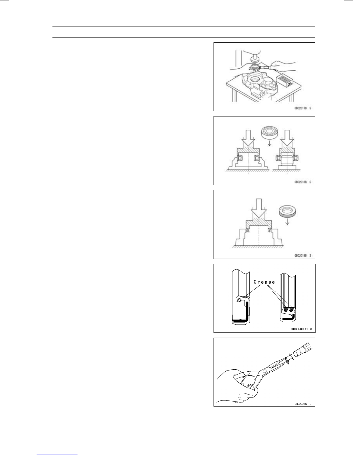
Press
For items such as bearings or oil seals that must be
pressed into place, apply small amount of oil to the contact area. Be sure to maintain proper alignment and use
smooth movements when installing.
Ball Bearing and Needle Bearing
Do not remove pressed ball or needle unless removal is
absolutely necessary. Replace with new ones whenever
removed. Press bearings with the manufacturer and size
marks facing out. Press the bearing into place by putting
pressure on the correct bearing race as shown.
Pressing the incorrect race can cause pressure between
the inner and outer race and result in bearing damage.
GENERAL INFORMATION 1-5
Oil Seal, Grease Seal
Do not remove pressed oil or grease seals unless removal
is necessary. Replace with new ones whenever removed.
Press new oil seals with manufacture and size marks facing
out. Make sure the seal is aligned properly when installing.
Apply specified grease to the lip of seal before installing
the seal.
Circlips, Cotter Pins
Replace circlips or cotter pins that were removed with new
ones. Take care not to open the clip excessively when installing to prevent deformation.
1-6 GENERAL INFORMATION
Before Servicing
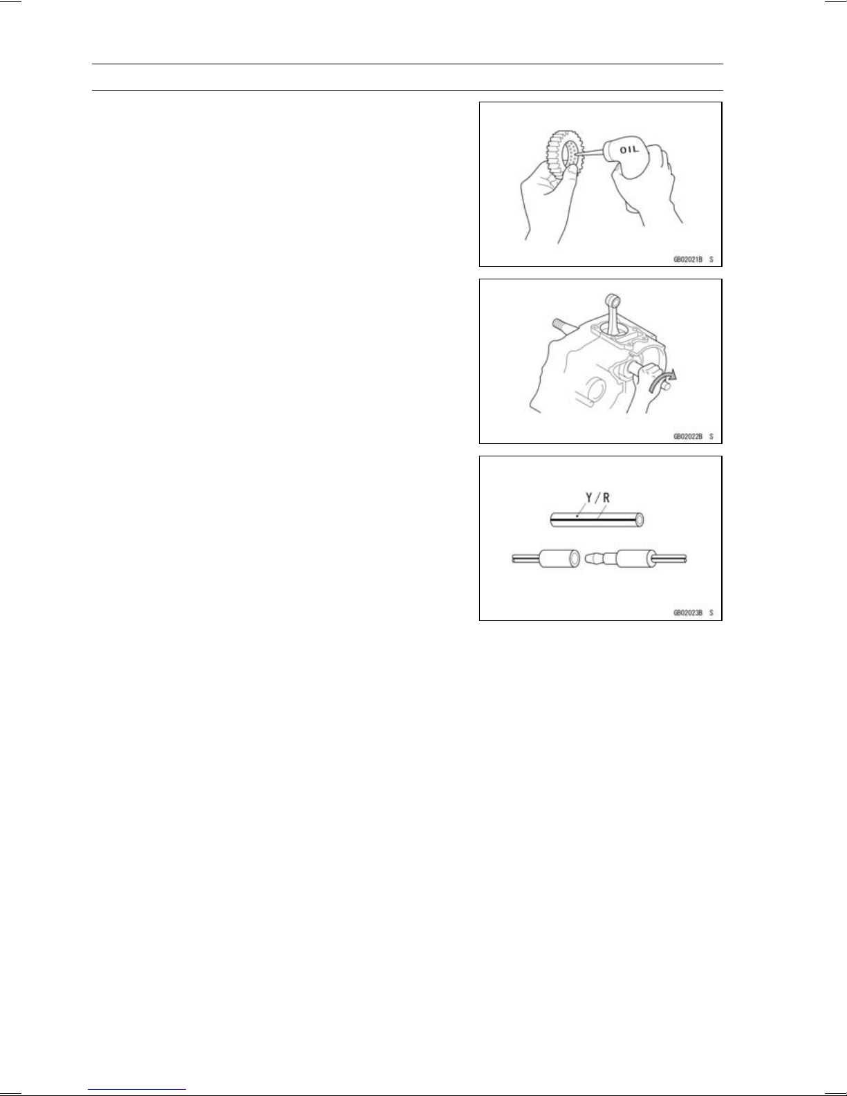
Lubrication
It is important to lubricate rotating or sliding parts during
assembly to minimize wear during initial operation. Lubrication points are called out throughout this manual, apply
the specific oil or grease as specified.
Direction of Engine Rotation
When rotating the crankshaft by hand, the free play
amount of rotating direction will affect the adjustment. Rotate the crankshaft to positive direction (clockwise viewed
from output side).
Electrical Wires
A two-color wire is identified first by the primary color and
then the stripe color. Unless instructed otherwise, electrical
wires must be connected to those of the same color.
GENERAL INFORMATION 1-7
Model Identification
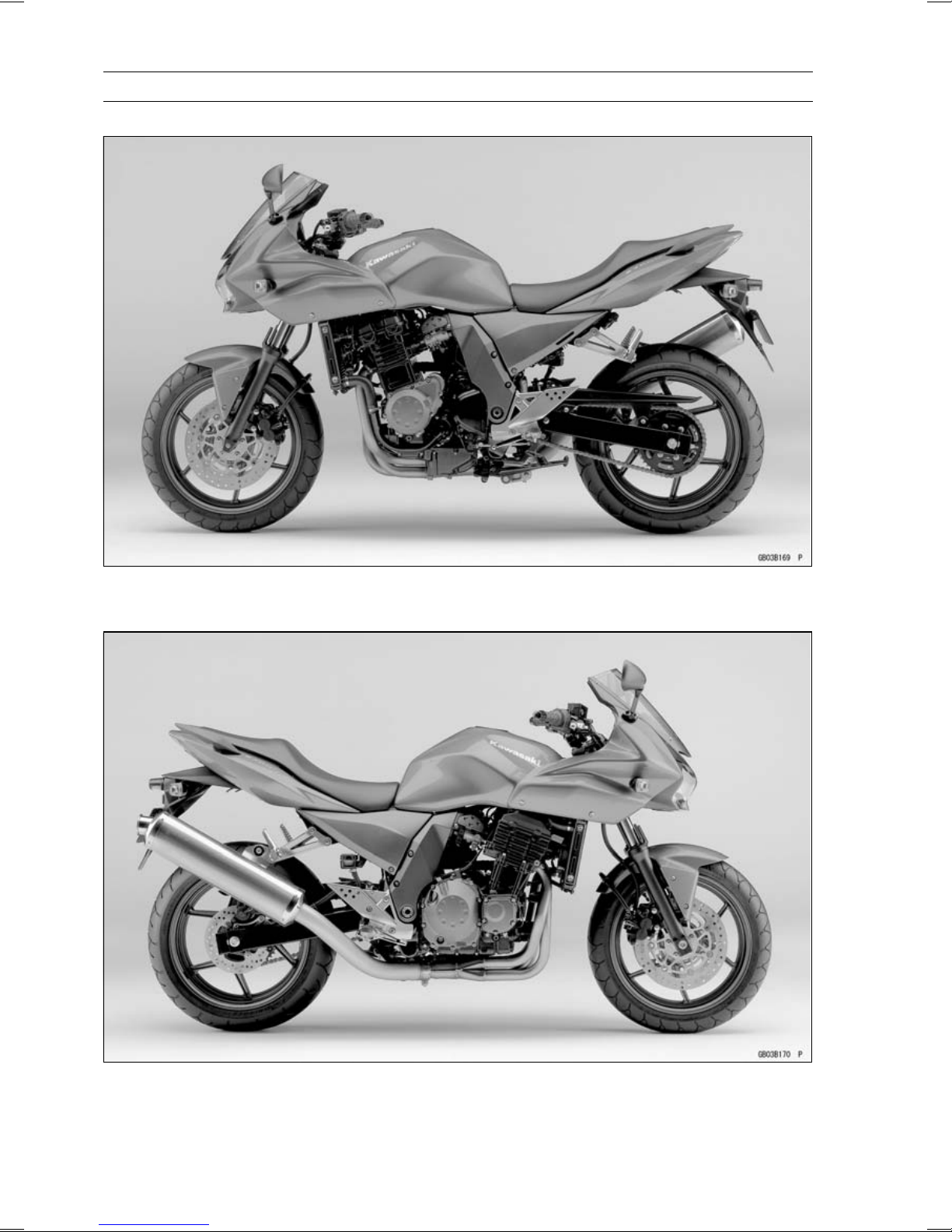
ZR750-K1 (United States and Canada) Left Side View
ZR750-K1 (United States and Canada) Right Side View
1-8 GENERAL INFORMATION
Model Identification
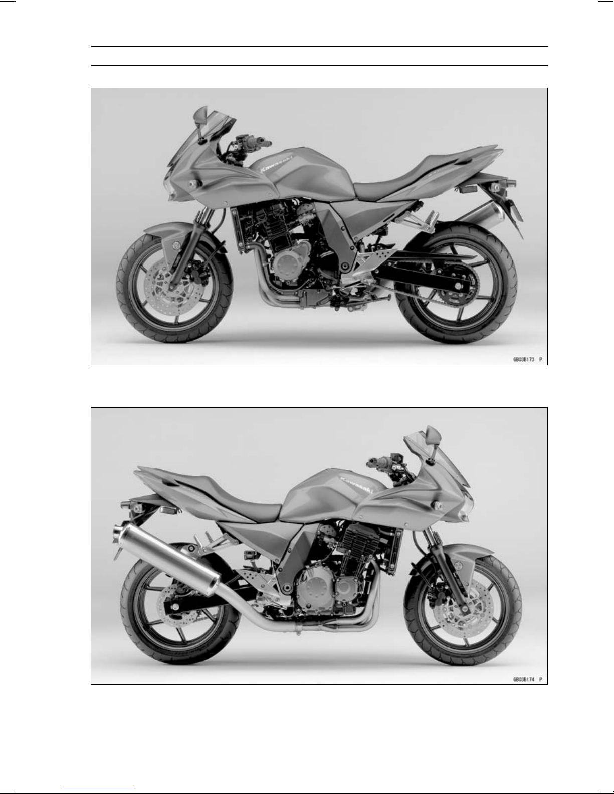
ZR750-K1 (Europe) Left Side View
ZR750-K1 (Europe) Right Side View

GENERAL INFORMATION 1-9
General Specifications
Items ZR750-K1
Dimensions
Overall Length 2 080 mm (81.9 in.)
Overall Width 780 mm (30.7 in.)
Overall Height 1 180 mm (46.5 in.)
Wheelbase 1 425 mm (56.1 in.)
Road Clearance 165 mm (6.5 in.)
Seat Height 805 mm (31.7 in.)
Dry Mass
Curb Mass:
Front 113 kg (249.2 lb)
Rear 109 kg (240.3 lb)
Fuel Tank Capacity 18 L (5.0 US gal.)
Performance
Minimum Turning Radius 2.9 m (9.5 ft)
Engine
Type 4-stroke, DOHC, 4-cylinder
Cooling System Liquid-cooled
Bore and Stroke 68.4 × 50.9 mm (2.7 × 2.0 in.)
Displacement 748 mL (45.64 cu in.)
Compression Ratio 11.3 : 1
Maximum Horsepower 81 kW (110 PS) @11 000 r/min (rpm),
Maximum Torque
Carburetion System FI (Fuel Injection) KEIHIN TTK34 × 4
Starting System Electric starter
Ignition System Battery and coil (transistorized)
Timing Advance Electronically advanced (digital igniter)
Ignition Timing From 10° BTDC @1 100 r/min (rpm) to 37° BTDC @5 800
Spark Plug NGK CR9EK or ND U27ETR
Cylinder Numbering Method Left to right, 1-2-3-4
Firing Order
Valve Timing:
Inlet
Open 38° BTDC
Close 66° ABDC
Duration 284°
Exhaust
Open 57° BBDC
Close 31° ATDC
199 kg (438.8 lb)
(MY) 80 kW (109 PS) @11 000 r/min (rpm)
(HR) 78.2 kW (106 PS) @11 000 r/min (rpm)
(US, CA) – – –
75 N·m (7.6 kgf·m, 55 ft·lb) @8 200 r/min (rpm),
(HR) 73 N·m (7.4 kgf·m, 54 ft·lb) @8 200 r/min (rpm)
(US, CA) – – –
r/min (rpm)
1-2-4-3

1-10 GENERAL INFORMATION
General Specifications
Items ZR750-K1
Duration 268°
Lubrication System Forced lubrication (wet sump)
Engine Oil:
Type API SE, SF or SG
API SH or SJ with JASO MA
Viscosity SAE 10W-40
Capacity 3.8L(4.0USqt)
Drive Train
Primary Reduction System:
Type Gear
Reduction Ratio 1.714 (84/49)
Clutch Type Wet multi disc
Transmission:
Type 6-speed, constant mesh, return shift
Gear Ratios:
1st 2.571 (36/14)
2nd 1.941 (33/17)
3rd 1.555 (28/18)
4th
5th
6th
Final Drive System:
Type Chain drive
Reduction Ratio 2.867 (43/15)
Overall Drive Ratio 5.382 @Top gear
Frame
Type Tubular, diamond
Caster (Rake Angle) 25°
Trail 107 mm (4.2 in.)
Front Tire:
Type Tubeless
Size 120/70 ZR17 M/C (58W)
Rear Tire:
Type Tubeless
Size 180/55 ZR17 M/C (73W)
Front Suspension:
Type Telescopic fork
Wheel Travel 120 mm (4.7 in.)
Rear Suspension:
Type Swingarm (uni-trak)
Wheel Travel 126 mm (5.0 in.)
Brake Type:
Front Dual discs
Rear
1.333 (28/21)
1.200 (24/20)
1.095 (23/21)
Single disc

GENERAL INFORMATION 1-11
General Specifications
Items ZR750-K1
Electrical Equipment
Battery 12 V 8 Ah
Headlight:
Type Semi-sealed beam
Bulb 12 V 55 W × 2/55 W (Hi/Lo)
Tail/Brake Light 12 V 0.5/4.1 W (LED)
Alternator:
Type Three-phase AC
Rated O utput 24 A/14 V @5 000 r/min (rpm)
Specifications are subject to change without notice, and may not apply to every country.
CA: Canada Model
US: United States
HR: With Honeycomb Catalytic Converter (Restricted Model)
MY: Malaysia Model
1-12 GENERAL INFORMATION
Technical Information - Air Inlet System
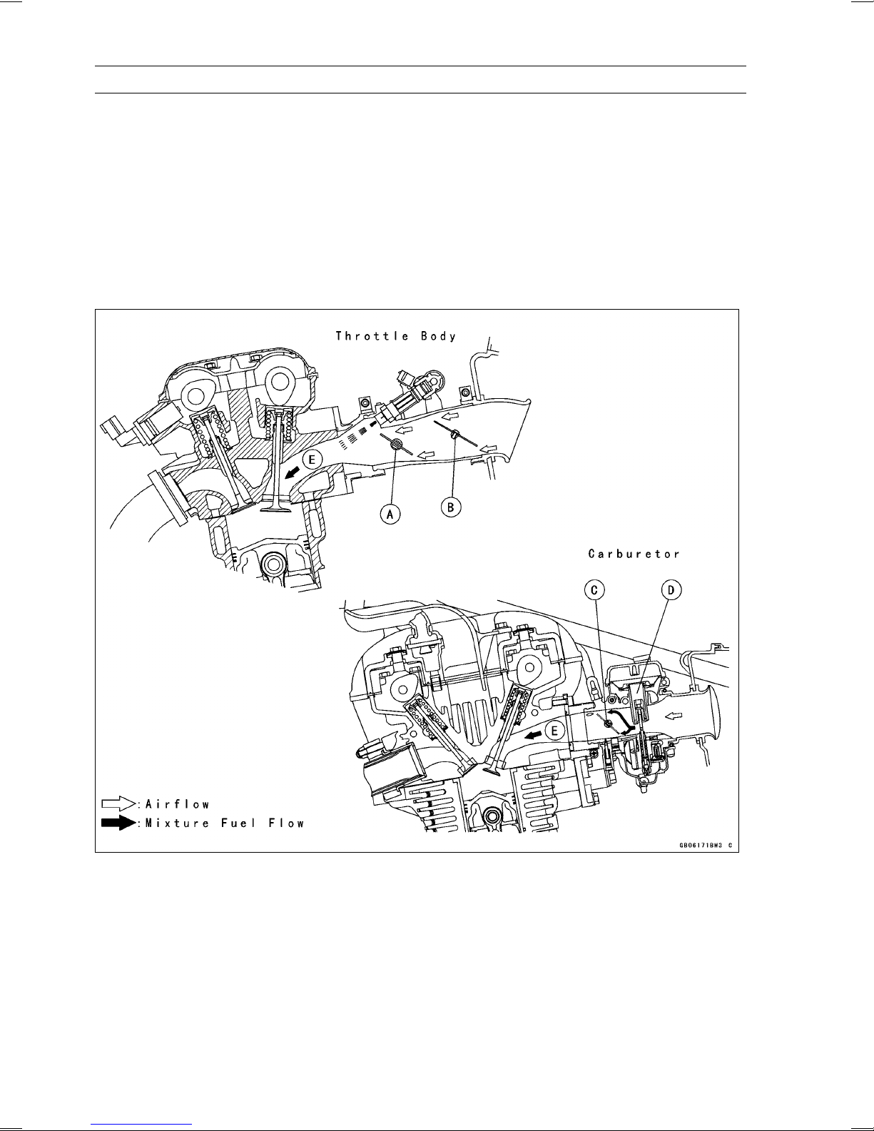
Subthrottle Control System
The ZR750-K models employs large bore throttle bodies to increase power output. However, sudden changes in throttle opening can cause hesitation and jerky throttle response with a single butterfly
valve in a large bore. Therefore two throttle valves are placed in each inlet tract, the main throttle valve
located closest to the cylinder and a subthrottle valve placed further up the inlet tract. The main throttle valve is operated by the rider when the throttle grip is turned clockwise or counterclockwise, while
the subthrottle valve is operated by a stepping motor controlled by the ECU. The subthrottle valve
automatically adjusts air inlet to more precisely match engine demand, so that when the main throttle
is opened quickly there is no hesitation or jerky response.
The subthrottle valves allow the fuel injection system to provide smooth throttle response, similar to
that of a constant velocity carburetor, no matter how quickly the throttle is opened.
A. Main Throttle Valve
B. Subthrottle Valve
C. Throttle Valve
D. Vacuum Piston
E. Inlet Air
GENERAL INFORMATION 1-13
Technical Information - Air Inlet System
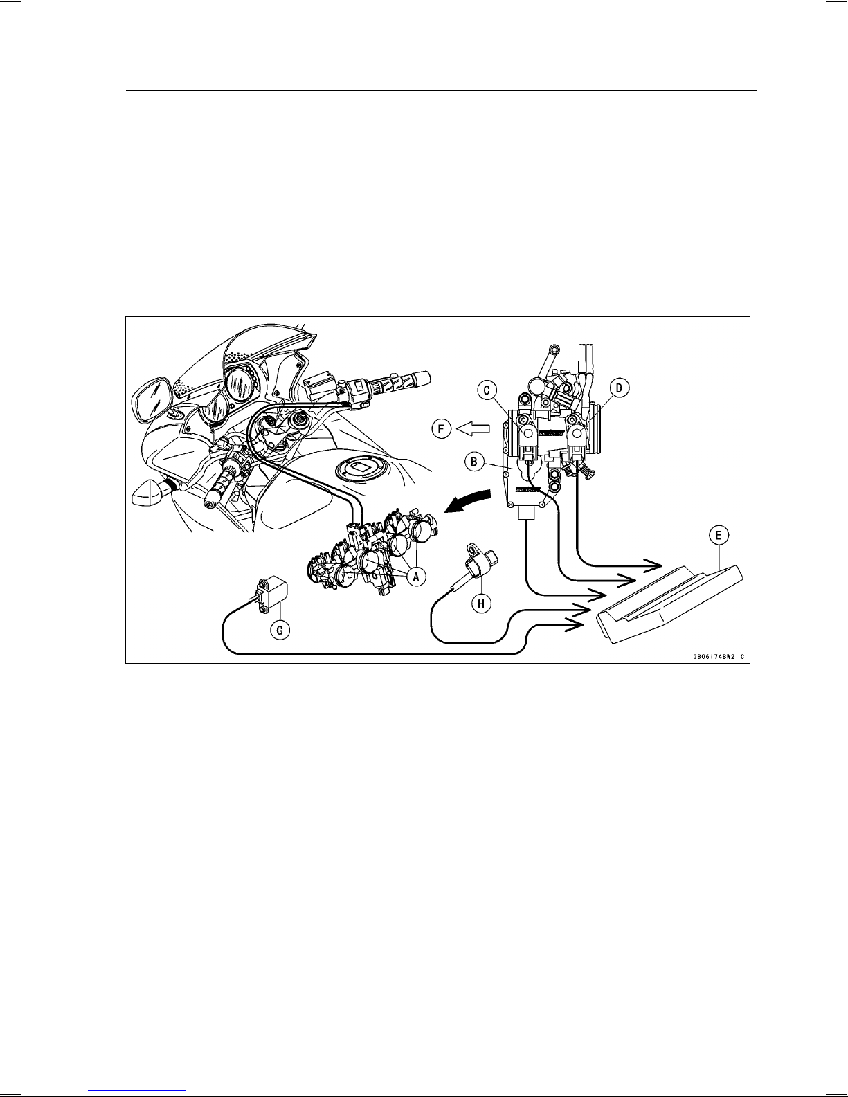
Operation
The subthrottle control system consists of the subthrottle valve, subthrottle valve actuator with a
stepping motor built in it, ECU, and subthrottle sensor. The subthrottle valve is built in the each throttle
body.
The subthrottle control system operates on the signal supplied from the ECU. The open/close operation of the subthrottle valve is performed by the subthrottle actuator which is controlled by the ECU
to change the current direction into the motor of the subthrottle valve actuator.
The subthrottle sensor detects the subthrottle valve actuator movement by measuring voltage and
the ECU determines the subthrottle valve angle based on the operation map.
When turning the ignition switch ON, every time the ECU automatically drives the subthrottle valve
from fully closed position to fully opened position. The ECU memorizes these positions and turns
back the subthrottle valve to the original point to confirm the subthrottle valve idling voltage.
A. Subthrottle Valves
B. Subthrottle Valve Actuator
C. Subthrottle Sensor
D. Main Throttle Sensor
E. ECU (Electronic Control Unit)
F. Air Cleaner Side
G. Crankshaft Sensor
H. Speed Sensor

1-14 GENERAL INFORMATION
Technical Information - New Ignition Interlock Side Stand
Outline
The New Ignition Interlock Side Stand System applied to ZR750-K models that cannot function if
gears are engaged and/or the side stand is not lifted upward even though clutch lever pulled in, which
differs from the traditional one. Refer to the tables below as to the engine starts and/or the driving at
each condition.
New Ignition Interlock Side Stand System
Side Stand Gear Position Clutch Lever Engine Start Engine Run
A Up Neutral Released Starts Continue running
B Up Neutral Pulled in Starts Continue running
C Up In Gear Released Doesn’t start Continue running
D Up In Gear Pulled in Starts Continue running
E Down Neutral Released
F Down Neutral Pulled in Starts Continue running
G Down In Gear Released Doesn’t start Stops
H Down In Gear Pulled in Doesn’t start Stops
Current Ignition Interlock Side Stand System
Side Stand Gear Position Clutch Lever Engine Start
A Up Neutral Released Starts Continue running
B Up Neutral Pulled in Starts Continue running
C Up In Gear Released Doesn’t start Continue running
D Up In Gear Pulled in Starts Continue running
E Down Neutral Released Starts Continue running
F Down Neutral Pulled in
Down
G
H Down In Gear Pulled in Start Continue running
In Gear
Relea
sed
Starts Continue running
Engine Run
Starts Continue running
Doesn
’t start
Stops
GENERAL INFORMATION 1-15
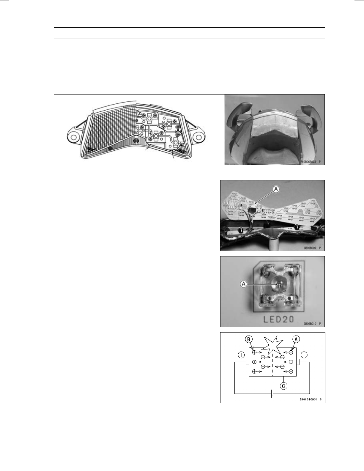
Technical Information - Tail/Brake Lights Employing LED
Outline
This model employs a tail/brake light containing 9 Light Emitting Diodes (LED). The LED emits luminous beams over a longer life span than those emitted from a traditional electric heated bulb (more
than 5 times longer), uses lower voltage, expends lower wattage (approx. 1/5), and is quicker responsing.
Due Position of LED Installation
The resistors, the diodes, and the Zener diodes are
mounted in the electronic circuits [A] of the LED, which
supplies the steady current and voltage to the light.
Light Emitting Diode (LED)
The Light Emitting Diode (LED) [A] is an element of semiconductor diode that converts applied voltage to light.
The LED emits luminous beams by the collision of negative charge electrons [A] and positive charge holes [B] when
applied the forward voltage and current to the PN junction
diode [C].

1-16 GENERAL INFORMATION
Technical Information - Tail/Brake Lights Employing LED
The emitting color differs according to the materials of
semi-conductors.
Materials of Semi-Conductor and Emitting Color
Materials of Semi-Conductor Emitting Color
GaAsP,
GaAlAs
GaP Green
GaN
Al: Aluminum
As: Arsenic
Ga: Gallium
N: Nitrogen
P: Phosphorus
Red
Blue
GENERAL INFORMATION 1-17
Technical Information - KAWASAKI LOW EXHAUST EMISSION SYSTEM
Since the emission regulations become more severe, Kawasaki has adopted a type of simplified
KAWASAKI LOW EXHAUST EMISSION SYSTEM (KLEEN), which have no catalyst protection system, according to each regulation of different countries.
The muffler with built-in catalyst has the same durability as the conventional muffler, however, do
not use leaded gasoline and do not coast with the ignition system OFF. Running the engine without
ignition damages catalyst.
Refer to the ZX900E Service Manual (Part No. 99924-1255) for more information about the KLEEN
(theory, maintenance, and handling precautions), including the secondary air injection system.
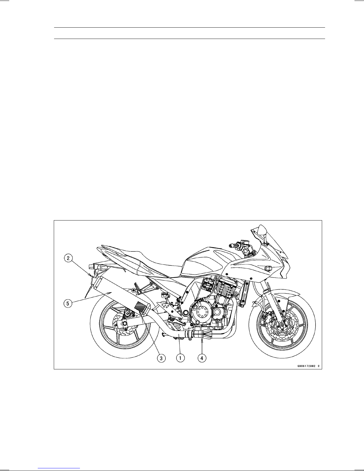
Honeycomb Type Catalytic Converter
The converter is a three-way catalytic converter, and its surface is covered with alumina upon which
○
platinum and rhodium are applied, and has a c ylindrical metallic honeycomb structure made by
bending a corrugated sheet and a flat sheet of stainless steel into a spiral of increasing diameter.
The honeycomb structure is convenient for the catalytic converter because it has a large surface
area but small size to react effectively and has low exhaust resistance. In addition, its inherent
strength helps resist vibration, and has simple structure welded directly on the silencer.
Generally, the temperature of the exhaust gas must be higher than activation temperature, so the
○
converters are installed in the exhaust manifold rear end where the temperature of exhaust gas is
still high. And, the converters will be activated even under low load conditions.
After the exhaust gas is diluted with the secondary air injection, the catalytic converter works well
○
because of rich oxygen to reduce CO, HC, and NO
emission within regulation.
This type of converter works more efficiently as a three-way c atalytic converter to reduce CO, HC,
○
and NO
x than the pipe type catalytic converter because of its more and denser catalysts.
x. Accordingly, we c an keep the exhaust gas
1. Manifold
2. Silencer
3. Honeycomb Type Catalyst
4. Mark for Manifold
5. Mark for Silencer
1-18 GENERAL INFORMATION
Technical Information - Immobilizer System (Equipped Models)
Overview
This system provides a theft proof device by means of matching a code between the inbuilt key
transponder and the ECU (Electronic Control Unit). If this code does not match, the fuel pump, injectors, ignition system, sub-throttle valve actuator and exhaust butterfly valve actuator will not operate
and the engine will not start.
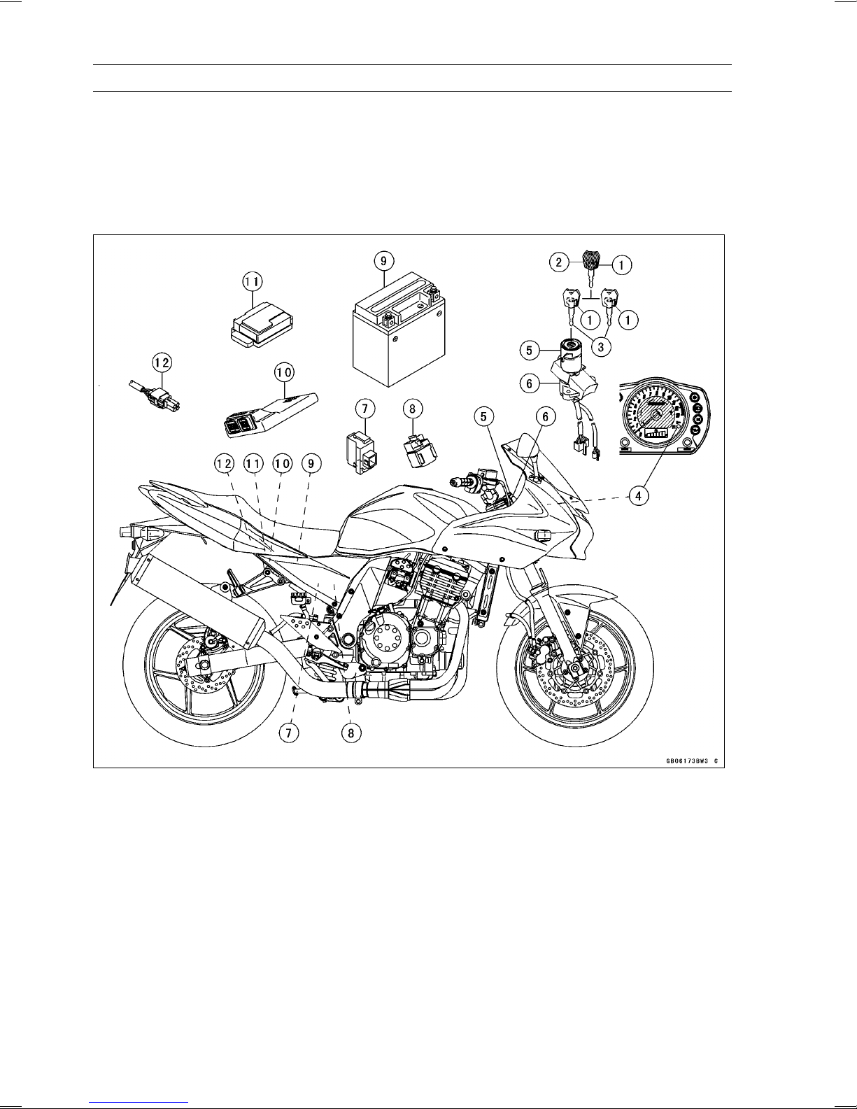
Related Parts and Function
1. Transponder (Inside Keys)
2. Master Key
3. User Keys
4. FI Indicator Light
5. Immobilizer Antenna
6. Ignition Switch
7. Immobilizer Amplifier
Master Key (1 piece)
The master key (colored red) has an inbuilt transponder, containing a master key code. These
codes are unique to each key. This code and an additional two user key codes must be registered
in the ECU for the system to operate. The master key is necessary when registering user keys and
should not be used as the main key to start the motorcycle except in emergencies (loss or damage of
user keys). It should be kept in a safe place.
8. Starter Relay
9. Battery
10. Electronic Control Unit (ECU)
11. Junction Box
12. Immobilizer/Kawasaki Diagnostic System
Connector

GENERAL INFORMATION 1-19
Technical Information - Immobilizer System (Equipped Models)
Transponder (in Keys)
The transponder (made by Texas Instruments, Inc.) has an integrated circuit with a unique code
that also calculates data sent by the ECU. When the ignition switch is turned ON, the transponder
is excited by the radio wave transmitted from the antenna and then transmits a unique code to the
antenna.
User Key (2 pieces)
The user keys (colored black) should be used when riding the motorcycle. These keys have unique
codes which differ from the master key. Up to a maximum of five user key codes can be stored by
the ECU at any one time. These codes can not be registered to the ECU without firstly registering the
master key code.
Antenna
The antenna transmits a radio wave to excite the transponder, receives the code from the transponder and then transmits the code to the ECU through the amplifier.
Ignition Switch
The ignition switch turns the main circuit ON and OFF.
Amplifier
The amplifier (which is approximately the same size as a match box), amplifies signals from the
antenna and the ECU.
ECU
The ECU has the capacity to store a maximum of six key code memories (one master and five user
keys). The owner can have a total of five user keys at any one time. The master key memory can not
be rewritten after initial registration, whereas the user key memories can be rewritten as necessary.
When the ECU communicates with the transponder, a cipher generator changes the code every time
it is used to avoid cloning.
FI Indicator Light
The condition or the failure of the immobilizer system is indicated by various patterns of the FI indicator light blinking.
Sequence of Operation
1. Turn ON the ignition switch, the ECU, amplifier and antenna start working, and the meter assembly
FI indicator lights up.
2. The transponder excited by radio waves transmitted from the antenna receives the ciphered code
from the ECU.
3. The transponder transmits the calculated result from the key’s unique code to the ECU.
4. The ECU compares this with its memorized code, and if they match the engine can start. At this
time, the FI indicator in the meter assembly is switched off.
1-20 GENERAL INFORMATION
Technical Information - Immobilizer System (Equipped Models)
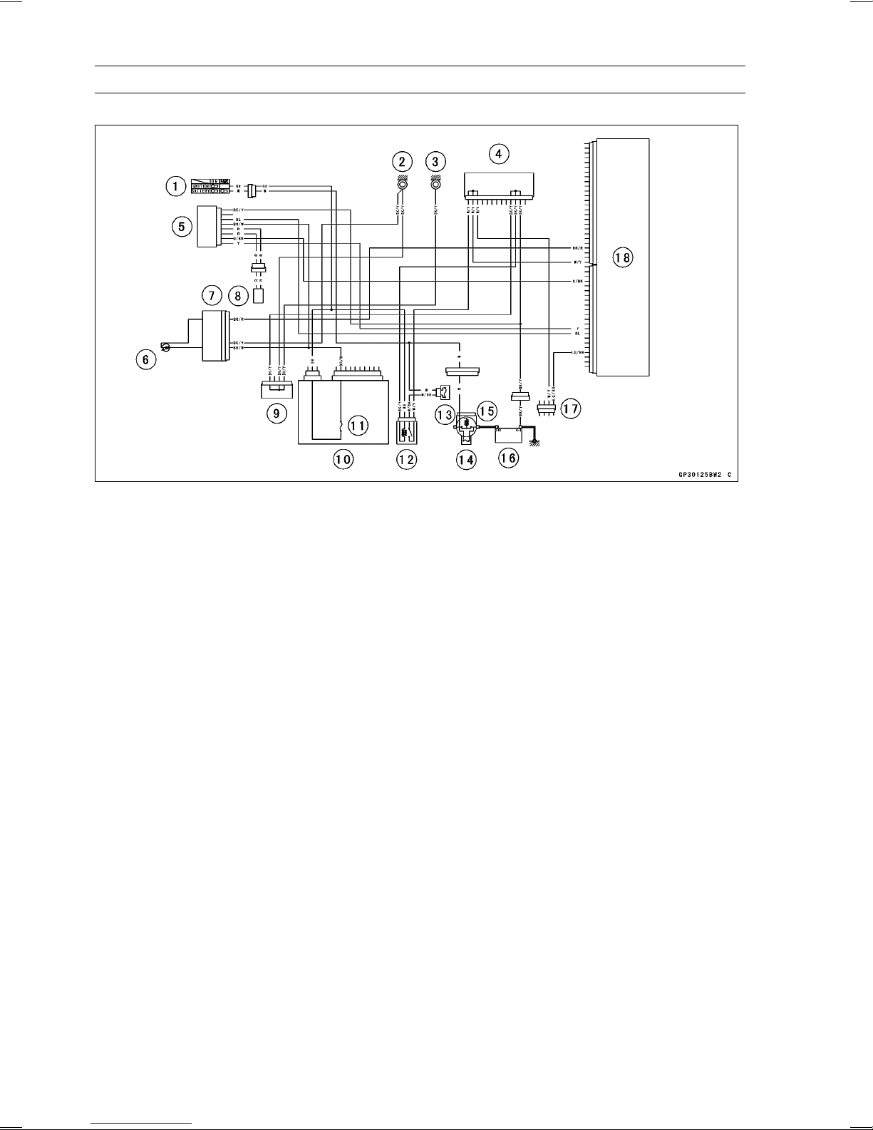
Immobilizer System Circuit
1. Ignition Switch
2. Meter Ground
3. Frame Ground
4. Joint Connector B
5. Immobilizer Amplifier
6. FI Indicator Light (LED)
7. Meter Unit
8. Immobilizer Antenna
9. Joint Connector A
10. Junction Box
11. Ignition Fuse 10 A
12. ECU Main Relay
13. ECU Fuse 15 A
14. Main Fuse 30 A
15. Starter Relay
16. Battery 12 V 8 Ah
17. Immobilizer/Kawasaki Diagnostic System
Connector
18. Electronic Control Unit (ECU)
 Loading...