


Kawasaki KX250F Service Manual

KX250F
Motorcycle
Service Manual

This quick reference guide will assist
you in locating a desired topic or procedure.
•Bend the pages back to match the
black tab of the desired chapter number with the black tab on the edge at
each table of contents page.
•Referto the sectional table of contents
for the exact pages to locate the specific topic required.
Quick Reference Guide
General Information 1
j
Periodic Maintenance 2
j
Fuel System 3
j
Cooling System 4
j
Engine Top End 5
j
Clutch 6
j
Engine Lubrication System 7
j
Engine Removal/Installation 8
j
Crankshaft/Transmission 9
j
Wheels/Tires 10
j
Final Drive 11
j
Brakes 12
j
Suspension 13
j
Steering 14
j
Frame 15
j
Electrical System 16
j
Appendix 17
j


KX250F
Motorcycle
Service Manual
All rights reserved. No parts of this publication may be reproduced, stored in a retrieval system, or
transmitted in any form or by any means, electronic mechanical photocopying, recording or otherwise,
without the prior written permission of Quality Assurance Division/Consumer Products & Machinery
Company/Kawasaki Heavy Industries, Ltd., Japan.
No liability can be accepted for any inaccuracies or omissions in this publication, although every possible
care has been taken to make it as complete and accurate as possible.
The right is reserved to make changes at any time without prior notice and without incurring an obligation
to make such changes to products manufactured previously. See your Motorcycle dealer for the latest
information on product improvements incorporated after this publication.
All information contained in this publication is based on the latest product information available at the time
of publication. Illustrations and photographs in this publication are intended for reference use only and may
not depict actual model component parts.
© 2009 Kawasaki Heavy Industries, Ltd. First Edition (1) : Jul. 28, 2009 (S)
LIST OF ABBREVIATIONS
A ampere(s) lb pound(s)
ABDC after bottom dead center
m
meter(s)
AC
alternating current min
minute(s)
ATDC after top dead center N newton(s)
BBDC before bottom dead center Pa pascal(s)
BDC bottom dead center PS horsepower
BTDC before top dead center psi pound(s) per square inch
°C degree(s) Celsius r revolution
DC direct current r/min, rpm revolution(s) per minute
F farad(s) TDC top dead center
°F degree(s) Fahrenheit TIR total indicator r eading
ft foot, feet V volt(s)
g gram(s) (mass) W watt(s)
h
hour(s) Ω ohm(s)
kg
(mass)
kgf (force)
L liter(s)
COUNTRY AND AREA CODES
AU Australia EUR Europe
BR Brazil US United States
CA Canada
Foreword
This manual is designed primarily for use by
trained mechanics in a properly equipped shop.
However,itcontainsenoughdetailandbasicinformationtomakeitusefultotheownerwho desiresto perform his own basic maintenanceand
repair work. A basic knowledge of mechanics,
the proper use of tools, and workshop procedures must be understood in order to carry out
maintenance and repair satisfactorily. Whenever the owner has insufficient experience or
doubts his ability to do the work, all adjustments, maintenance, and repair should be carried out only by qualified mechanics.
In order to perform the work efficiently and
to avoid costly mistakes, read the text, thoroughly familiarize yourself with the procedures
beforestarting work, and then do the work ca
refully in a clean area. Whenever special tools or
equipment are specified, do not use makeshift
tools or equipment. Precision measurem
ents
can only be made if the proper instruments are
used, and the use of substitute tools may adversely affect safe operation.
To get the longest life out of your vehicle:
•
Follow the Periodic Maintenance Chart in the
Service Manual.
•
Be alert for problems and non-scheduled
maintenance.
•
Use proper tools and genu
ine Kawasaki Motorcycle parts. Special tools, gauges, and
testers that are necessary when servicing
Kawasaki motorcycle
s are introduced by the
Service Manual. Genuine parts provided as
spare parts are listed in the Parts Catalog.
•
Follow the procedu
res in this manual care-
fully. Don’t take shortcuts.
•
Rememberto keep completerecords ofmaintenance and r
epair with dates and any new
parts installed.
How to Use This Manual
In this manual, the product is divided into
its major systems and these systems make up
the manual’s chapters. The Quick Reference
Guide shows you all of the product’s system
and assists in locating their chapters. Each
chapter in turn has its own comprehensive Table of Contents.
Forexample, if youwant stickcoil information,
use the Quick Reference Guide to locate the
Electrical System chapter. Then, use the Table
of Contents on the first page of the chapter to
find the Stick Coil section.
Whenever you see symbols, heed their instructions! Always follow safe operating and
maintenance practices.
DANGER
DANGER indicates a hazardous situa-
tion which, if not avoided, will result in
death or serious injury.
WARNING
WARNING indicates a hazardous situa-
tion which, if not avoided, could result
in death or serious injury.
CAUTION
CAUTION indicates a hazardous situa-
tion which, if not avoided, could result
in minor or moderate injury.
NOTICE
NOTICE is used to address practices not
related to personal injury.
This manual contains four more symbols
which will help you distinguish different types
of information.
NOTE
○
This note symbol indicates points of par-
ticular interest for more efficient and con-
venient operation.
•
Indicates a procedural step or work to be
done.
○
Indicates a procedural sub-step or how to do
the work of the procedural step it follows. It
also precedes the text of a NOTE.
Indicates a conditional step or what action to
takebased on the resultsofthe test or inspec-
tion in the procedural step or sub-step it fol-
lows.
In most chapters an exploded view illustration
of the system components follows the Table of
Contents. In these illustrations you will find the
instructionsindicating which parts require specified tightening torque, oil, grease or a locking
agent during assembly.


GENERAL INFORMATION 1-1
1
General Information
Table of Contents
Before Servicing ..................................................................................................................... 1-2
Model Identification................................................................................................................. 1-7
General Specifications............................................................................................................ 1-8
Unit Conversion T able............................................................................................................ 1-10
1-2 GENERAL INFORMATION
Before Servicing
Before starting to perform an inspection service or carry out a disassembly and reassembly operation on a motorcycle, read the precautions given below. To facilitate actual operations, notes, illustrations, photographs, cautions, and detailed descriptions have been included in each chapter wherever
necessary. This section explains the items that require particular attention during the removal and
reinstallation or disassembly and reassembly of general parts.
Especially note the following:
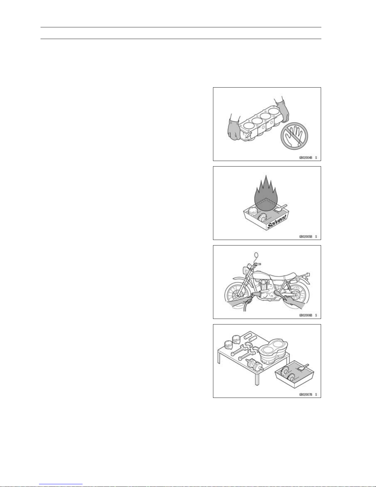
Edges of Parts
Lift large or heavy parts wearing gloves to prevent injury
from possible sharp edges on the parts.
Solvent
Use a high-flash point solvent when cleaning parts. High
-flash point solvent should be used according to directions
of the solvent manufacturer.
Cleaning Vehicle before Disassembly
Clean the vehicle thorou
ghly before disassembly. Dirt or
otherforeign materials enteringinto sealed areas duringvehicle disassembly can cause excessive wear and decrease
performance of t
he vehicle.
Arrangement and Cleaning of Removed Parts
Disassembled parts are easy t o confuse. Arrange the
parts according to the order the parts were disassembled
and clean the parts in order prior to assembly.
GENERAL INFORMATION 1-3
Before Servicing
Storage of Removed Parts
After all the parts including subassemblyparts havebeen
cleaned, store the parts in a clean area. Put a clean cloth
or plastic sheet over the parts to protect from any foreign
materials that may collect before re-assembly.
Inspection
Reuse of worn or damaged parts may lead to serious accident. Visually inspect removed parts for corrosion,discoloration, or other damage. Refer to the appropriate sections
of this manual for service limits on individual parts. Replace
the parts if any damage has been found or if the part is beyond its service limit.
Replacement Parts
Replacement parts must be KAWASAKI genuine or
recommended by KAWASAKI. Gaskets, O-rings, oil seals,
grease seals, circlips, cotter pins or self-locking nuts must
be replaced with new ones whenever disassembled.
Assembly Order
In most cases assembly order is the reverseof disassembly, however, if assembly order is provided in this Service
Manual, follow the procedures given.
Tightening Sequence
Generally, when installing a part with several bolts, nuts,
or screws, start them all in their holes and t ighten them to
a snug fit. Then tighten them according to the specified sequence to prevent case warpage or deformation which can
lead to malfunction. Conversely when loosening the bolts,
nuts, or screws, first loosen all of them by about a quarter turn and then remove them. If the specified tightening
sequence i s not indicated, tighten the fasteners alternating
diagonally.
1-4 GENERAL INFORMATION
Before Servicing
Tightening Torque
Incorrect torque applied to a bolt, nut, or screw may
lead to serious damage. Tighten fasteners to the specified
torque using a good quality torque wrench. Often, the
tightening sequence is followed twice-initial tightening and
final tightening with torque wrench.
Force
Use common sense during disassembly and assembly,
excessiveforce can cause expensive or hard to repair damage. When necessary, remove screws that have a non
-permanent locking agent applied using an impact driver.
Use a plastic-faced mallet whenever tapping is necessary.
Gasket, O-ring
Hardening, shrinkage, or dam
age of both gaskets
and O-rings after disassembly can reduce sealing performance. Remove old gaskets and clean the sealing
surfaces thoroughly so th
at no gasket material or other
material remains. Install new gaskets and replace used
O-rings when re-assembling.
Liquid Gasket, Non-permanent Locking Agent
For applications that require Liquid Gasket or a
Non-permanent Locking Agent, clean the surfaces so
that no oil residue remains before applying liquid gasket or
non-permanent locking agent. Do not apply them excessively. Excessive application can clog oil passages and
cause serious damage.
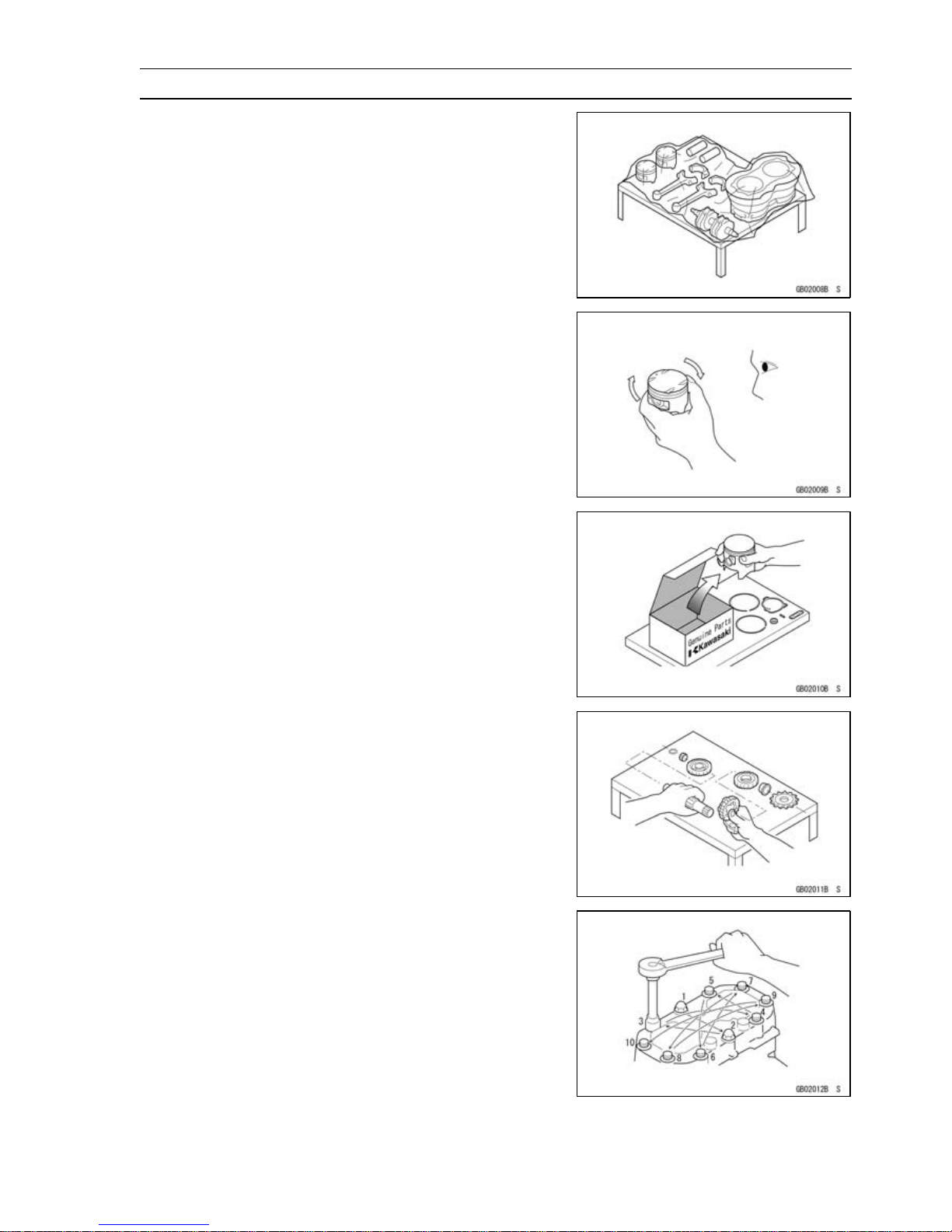
Press
For items such as bearings or oil seals that must be
pressed into place, apply small amount of oil to the contact area. Be sure to maintain proper alignment and use
smooth movements when installing.
GENERAL INFORMATION 1-5
Before Servicing
Ball Bearing and Needle Bearing
Do not remove pressed ball or needle unless removal is
absolutely necessary. Replace with new ones whenever
removed. Press bearings with the manufacturer and size
marks facing out. Press the bearing into place by putting
pressure on the correct bearing race as shown.
Pressing the incorrect race can cause pressure between
the inner and outer race and result in bearing damage.
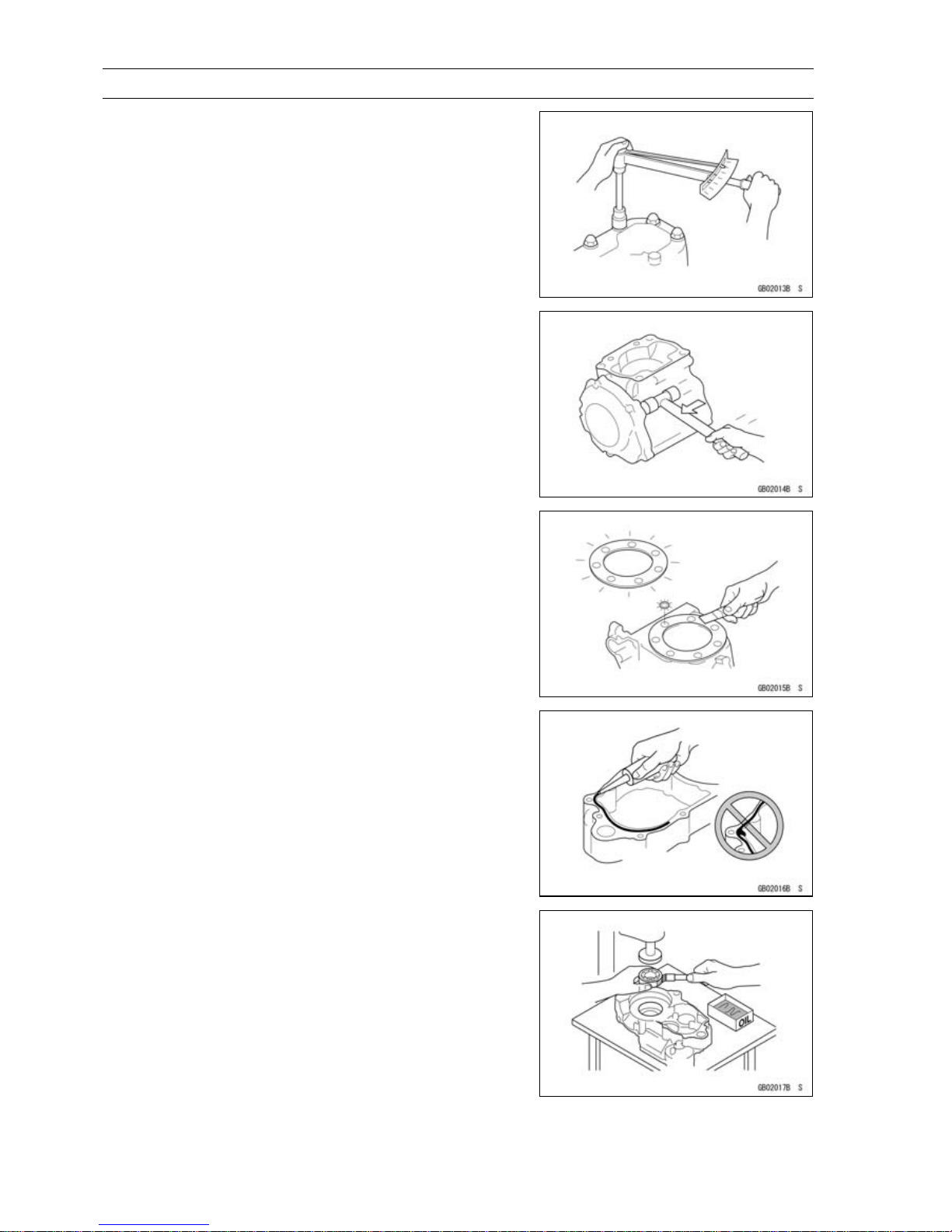
Oil Seal, Grease Seal
Donot remove pressedoil or greaseseals unlessremoval
is necessary. Replace with new ones whenever removed.
Pressnew oil seals with manufacture and size marks facing
out. Make sure the seal is aligned properly when installing.
Apply specified grease to the lip of seal before installing
the seal.
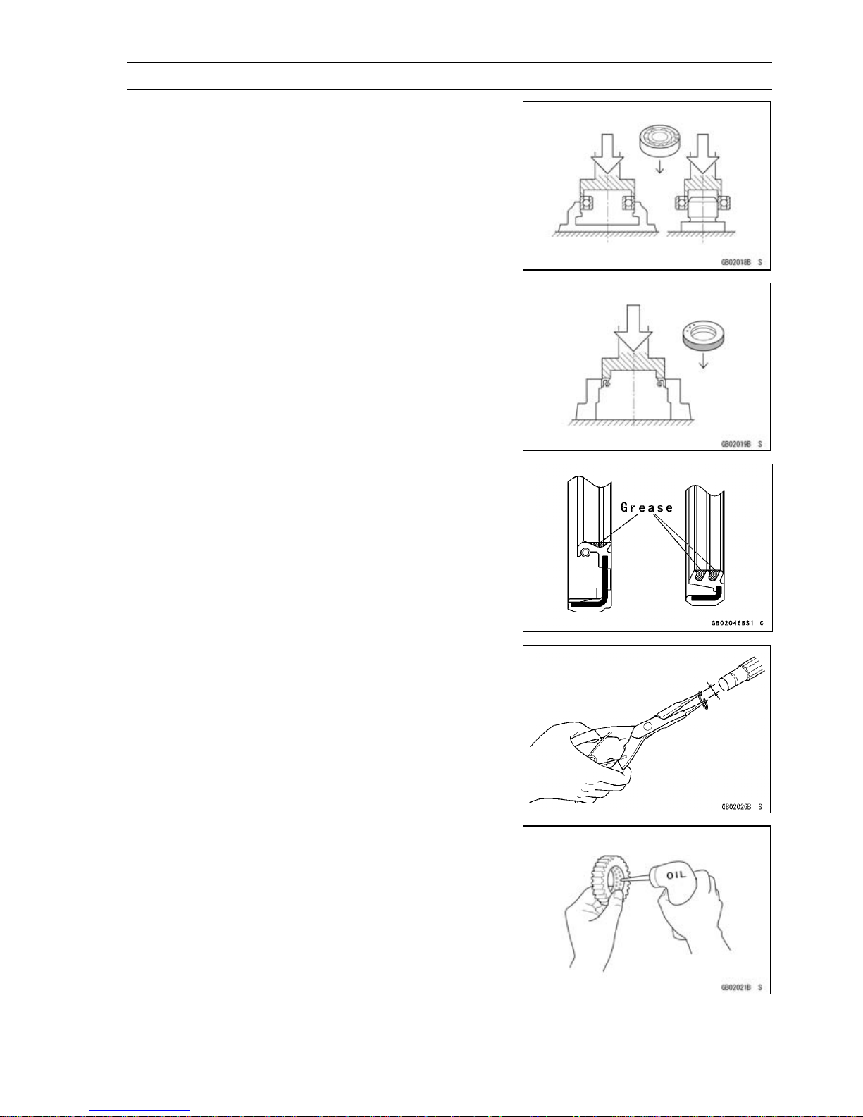
Circlips, Cotter Pins
Replacecirclips orcotter pinst hat were removedw ith new
ones. Take care not to open the clip excessively when installing to prevent deformation.
Lubrication
It is important to lubricate rotating or sliding parts during
assembly to minimize wear during initial operation. Lubrication points are called out throughout this manual, apply
the specific oil or grease as specified.
1-6 GENERAL INFORMATION
Before Servicing
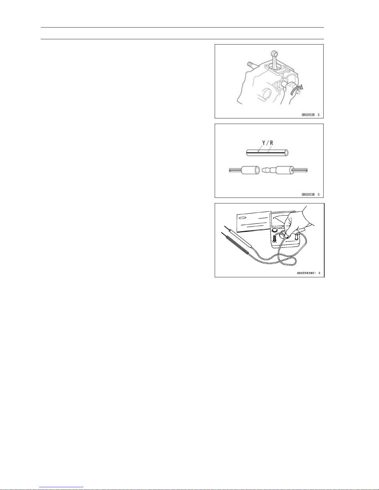
Direction of Engine Rotation
When rotating the crankshaft by hand, the free play
amount of rotating direction will affect the adjustment. Rotate the crankshaft to positive direction (clockwise viewed
from output side).
Electrical Leads
A two-color lead is identified first by theprimary color and
then the stripe color. Unless instructedotherwise, electrical
leads must be connected to those of the same color.
Instrument
Use a meter that has enough acc
uracy for an accurate
measurement. Read the manufacture’s instructions thoroughly before using the meter. Incorrect values may lead
to improper adjustments.
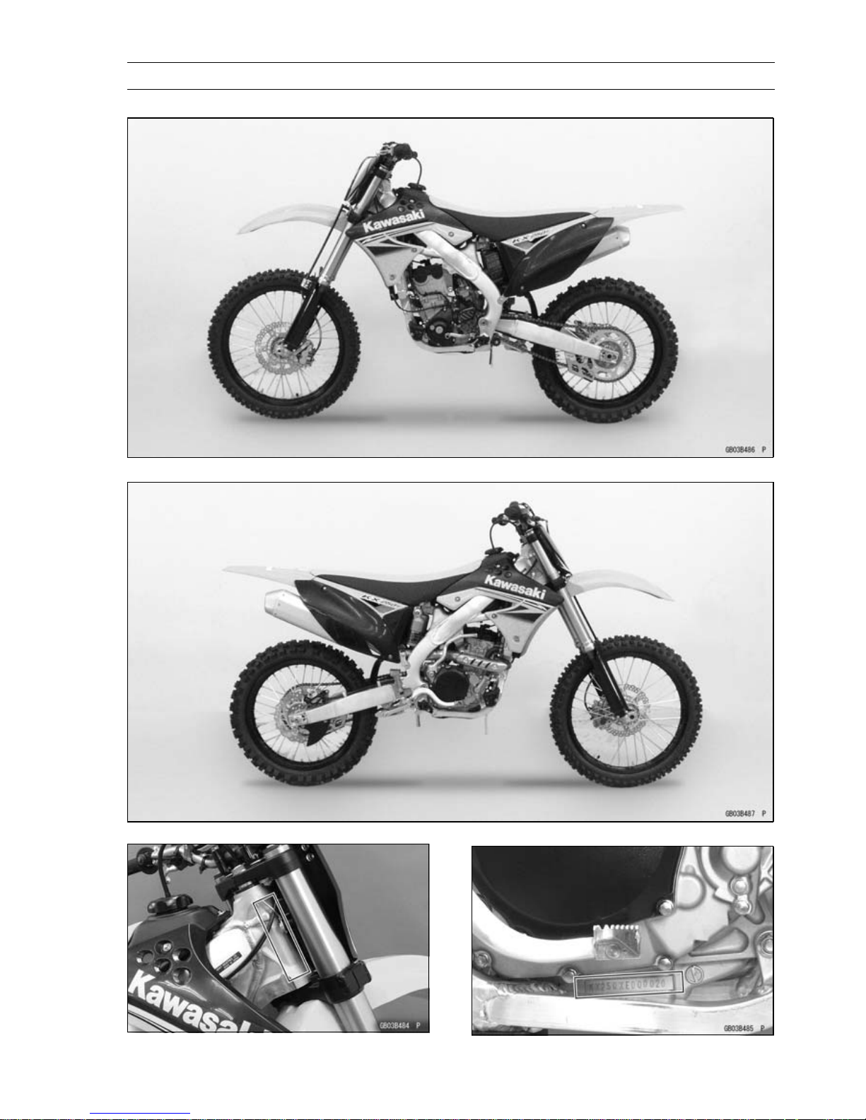
GENERAL INFORMATION 1-7
Model Identification
KX250XAF Left Side View
KX250XAF Right Side View
Frame Number Engine Number

1-8 GENERAL INFORMATION
General Specifications
Items KX250XAF
Dimensions
Overall Length 2 170 mm (85.43 in.)
Overall Width 820 mm (32.3 in.)
Overall Height 1 270 mm (50.00 in.)
Wheelbase 1 470 mm (57.87 in.)
Road Clearance 340 mm (13.4 in.)
Seat Height 955 mm (37.6 in.)
Curb Mass: 105.1 kg (231.7 lb)
(US, CA) 105.0 kg (231.5 lb)
Front 50.8 kg (112 lb)
Rear 54.3 kg (119.7 lb)
(US, CA) 54.2 kg (119.5 lb)
Fuel Tank Capacity 8.0 L (2.1 US gal)
Engine
Type 4-stroke, single cylinder, DOHC 4 valve
Cooling System Liquid-cooled
Bore and Stroke 77.0 × 53.6 mm (3.03 × 2.11 in.)
Displacement
249 cm³ (15.2 cu in.)
Compression Ratio
13.2 : 1
Carburetion System Carburetor, KEIHIN FCR-MX37
Starting System Primary kick
Ignition System Digital AC-CDI
Timing Advance Electronically advanced
Ignition Timing BTDC 8° @2 000 r/min (rpm)
Spark Plug:
Standard NGK CR8E
Option NGK CR9E
Valve Timing:
Inlet:
Open BTDC 41°
Close ABDC 71°
Duration 292°
Exhaust:
Open BBDC 69°
Close ATDC 49°
Duration 298°
Lubrication System Forced lubrication (semi-dry sump)
Engine Oil:
Grade API SG, SH, SJ or SL with JASO MA, MA1 or MA2
Viscosity SAE 10W-40
Capacity 1.0 L (1.1 USqt)

GENERAL INFORMATION 1-9
General Specifications
Items KX250XAF
Drive Train
Primary Reduction System:
Type Gear
Reduction Ratio 3.350 (67/20)
Clutch Type Wet multi disc, Manual
Transmission:
Type 5-speed, constant mesh, return shift
Gear Ratios:
1st 2.142 (30/14)
2nd 1.769 (23/13)
3rd 1.444 (26/18)
4th 1.200 (24/20)
5th 1.045 (23/22)
Final Drive System:
Type Chain drive
Reduction Ratio
3.692 (48/13)
Overall Drive Ratio 12.931 @Top gear
Frame
Type
Semi-double cradle
Steering Angle 42° to either side
Caster (Rake Angle) 27.4°
Trail 118.6 mm (4.669 in.)
Front Wheel:
Tire Size 80/100-21 51M
Tire Make/Type BRIDGESTONE M403, Tube type
Rim Size 21 × 1.60
Rear Wheel:
Tire Size 100/90-19 57M
Tire Make/Type BRIDGESTONE M404, Tube type
Rim Size 19 × 1.85
Front Suspension:
Type Telescopic fork (upside down)
Wheel Travel 315 mm (12.4 in.)
Rear Suspension:
Type Swingarm (New Uni-trak)
Wheel Travel 310 mm (12.2 in.)
Brake Type:
Front and Rear Single disc
Effective Disc Diameter:
Front
225 mm (8.86 in.)
Rear
215 mm (8.46 in.)
Specifications are subject to change without notice, and may not apply to every country.
1-10 GENERAL INFORMATION
Unit Conversion Table
Prefixes for Units:
Prefix Symbol
Power
mega M × 1 000 000
kilo k × 1 000
centi c ×0.01
milli m × 0.001
micro µ × 0.000001
Units of Mass:
kg ×2.205=lb
g × 0.03527 = oz
Units of Volume:
L × 0.2642 = gal (US)
L × 0.2200 = gal (imp)
L × 1.057 = qt (US)
L × 0.8799 = qt (imp)
L×2.113=
pint (US)
L × 1.816 = pint (imp)
mL × 0.03381 = oz (US)
mL × 0.02816 = oz (imp)
mL × 0.06102 = cu in
Units of Force:
N × 0.1020 = kgf
N × 0.2248 = lb
kgf × 9.807 = N
kgf × 2.205 = lb
Units of Length:
km × 0.6214 = mile
m × 3.281 =
ft
mm × 0.03937 = in
Units of Torque:
N·m × 0.1020 = kgf·m
N·m × 0.7376 =
ft·lb
N·m × 8.851 = in·lb
kgf·m × 9.807 = N·m
kgf·m
× 7.233 =
ft·lb
kgf·m
× 86.80 = in·lb
Units of Pressure:
kPa × 0.01020 = kgf/cm²
kPa × 0.1450 = psi
kPa × 0.7501 = cm Hg
kgf/cm² × 98.07 = kPa
kgf/cm² × 14.22 = psi
cmHg×1.333=kPa
Units of Speed:
km/h × 0.6214 = mph
Units of Power:
kW ×1.360=PS
kW ×1.341=HP
PS × 0.7355 = kW
PS × 0.9863 = HP
Units of Temperature:

PERIODIC MAINTENANCE 2-1
2
Periodic Maintenance
Table of Contents
Periodic Maintenance Chart ................................................................................................... 2-3
Torque and Locking Agent...................................................................................................... 2-5
Specifications ......................................................................................................................... 2-9
Special Tools .......................................................................................................................... 2-11
Periodic Maintenance Procedures.......................................................................................... 2-12
Fuel System......................................................................................................................... 2-12
Fuel Hose and Connection Inspection.............................................................................. 2-12
Throttle Grip (Throttle Cable) Free Play Inspection .......................................................... 2-12
Throttle Grip (Throttle Cable) Free Play Adjustment......................................................... 2-12
Hot Starter Lever (Hot Starter Cable) Free Play Inspection.............................................. 2-13
Idle Speed (Carburetor) Inspection .................................................................................. 2-13
Idle Speed (Carburetor) Adjustment ................................................................................ 2-14
Air Cleaner Element Cleaning and Inspection.................................................................. 2-15
Fuel System Clean............................................................................................................ 2-17
Cooling System.................................................................................................................... 2-18
Coolant Level Inspection................................................................................................... 2-18
Coolant Deterioration Inspection....................................................................................... 2-19
Water Hoses and Connections Inspection........................................................................ 2-19
Engine Top End ................................................................................................................... 2-19
Valve Clearance Inspection .............................................................................................. 2-19
Valve Clearance Adjustment............................................................................................. 2-20
Cylinder Head Warp Inspection ........................................................................................ 2-22
Cylinder Wear Inspection.................................................................................................. 2-22
Piston/Cylinder Clearance Inspection............................................................................... 2-23
Piston, Piston Ring and Piston Pin Replacement ............................................................. 2-23
Exhaust System Inspection............................................................................................... 2-23
Muffler Baffle Replacement............................................................................................... 2-24
Clutch................................................................................................................................... 2-25
Clutch Operation Inspection.............................................................................................. 2-25
Clutch Plates Inspection ................................................................................................... 2-26
Engine Lubrication System.................................................................................................. 2-26
Engine Oil Change............................................................................................................ 2-27
Oil Filter Change............................................................................................................... 2-28
Breather Hose Inspection ................................................................................................. 2-28
Crankshaft/Transmission..................................................................................................... 2-29
Crankshaft Inspection ....................................................................................................... 2-29
Wheel/Tires.......................................................................................................................... 2-29
Air Pressure Inspection/Adjustment.................................................................................. 2-29
Tires Inspection.................................................................................................................2-30
Spoke Tightness Inspection.............................................................................................. 2-30
Rim R unout Inspection...................................................................................................... 2-30
Wheel Bearing Inspection................................................................................................. 2-31
Final Drive............................................................................................................................ 2-31
Drive Chain Wear Inspection ............................................................................................ 2-31
Drive Chain Slack Inspection............................................................................................ 2-32
Drive Chain Slack Adjustment .......................................................................................... 2-33
Drive Chain Lubrication..................................................................................................... 2-34
Sprocket Wear Inspection................................................................................................. 2-34
Rear Sprocket Warp (Runout) Inspection......................................................................... 2-34
Brakes.................................................................................................................................. 2-35

2-2 PERIODIC MAINTENANCE
Brake Lever and Pedal Adjustment .................................................................................. 2-35
Brake Fluid Level Inspection............................................................................................. 2-36
Brake Fluid Change.......................................................................................................... 2-37
Brake Pad Wear Inspection .............................................................................................. 2-39
Brake Master Cylinder Rubber Parts Replacement.......................................................... 2-39
Caliper Rubber Parts Replacement.................................................................................. 2-41
Brake Hoses and Connections Inspection........................................................................ 2-44
Brake Hose Replacement................................................................................................. 2-44
Suspension.......................................................................................................................... 2-46
Front Fork Inspection........................................................................................................ 2-46
Front Fork Oil Change (each fork leg) .............................................................................. 2-46
Rear Shock Absorber Oil Change..................................................................................... 2-56
Swingarm and Uni-Trak Linkage Inspection ..................................................................... 2-65
Swingarm and Uni-Trak Linkage Pivot Lubrication........................................................... 2-65
Steering ............................................................................................................................... 2-66
Steering Inspection........................................................................................................... 2-66
Steering Adjustment ......................................................................................................... 2-66
Steering Stem Bearing Lubrication................................................................................... 2-68
Frame .................................................................................................................................. 2-68
Frame Inspection.............................................................................................................. 2-68
Electrical System................................................................................................................. 2-69
Spark Plug Cleaning and Inspection................................................................................. 2-69
Spark Plug Replacement.................................................................................................. 2-69
General Lubrication and Cable Inspection........................................................................... 2-70
Lubrication........................................................................................................................ 2-70
Nut, Bolt, and Fastener Tightness Inspection...................................................................... 2-71
Tightness Inspection ......................................................................................................... 2-71

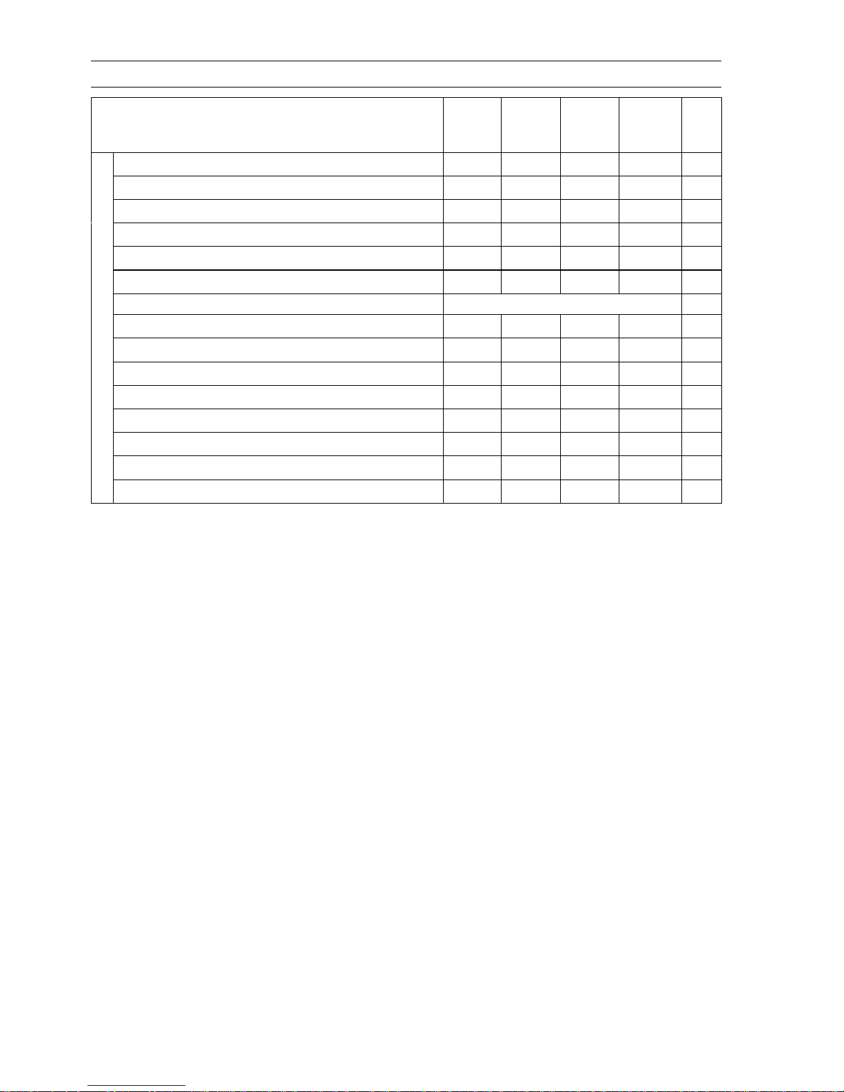
PERIODIC MAINTENANCE 2-3
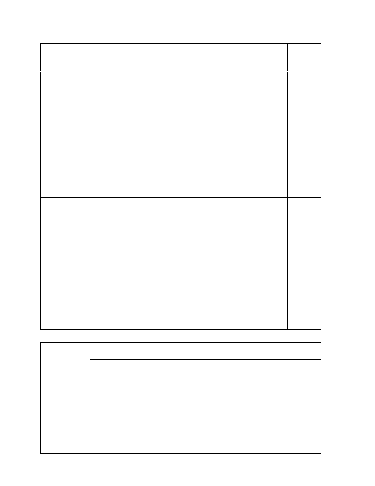
Periodic Maintenance Chart
The maintenancemust be done in accordance with this chart to keepthemotorcyclein good running
condition.
FREQUENCY
OPERATION
Each
race or
2.5 hr
Every 3
races or
7.5 hr
Every 6
races or
15 hr
Every12
races or
30 hr
See
Page
Spark plug - clean, inspect †
•
2-69
Spark plug - replace
•
2-69
Clutch - inspect
•
2-25
Clutch plates - inspect †
•
2-26
Throttle cable - inspect and adjust
•
2-12
Air cleaner element - clean
•
2-15
Air cleaner element - replace If damaged 2-15
Carburetor - inspect and adjust
•
2-13
Engine Oil - change
•
2-27
Piston and piston ring - replace
•
2-23
Cylinder head, cylinder - inspect
•
2-22
Piston pin - replace
•
2-23
Valve clearance - inspect †
•
2-19
Hot starter cable - inspect
•
2-13
Oil filter - replace
•
2-28
Exhaust system - inspect†
•
2-23
Muffler baffle- change
•
2-24
Kick pedal and shift pedal - clean
•
–
Engine sprocket - inspect †
•
2-34
Coolant level - inspect
•
2-18
Water hoses and connections - inspect †
•
2-19
Crankshaft - inspect
•
2-29
E
N
G
I
N
E
Breather hose - inspect
•
2-28
Brake - adjust †
•
2-35
Brake pad wear - inspect †
•
2-39
Brake fluid level - inspect †
•
2-36
Brake fluid - change Every 2 years 2-37
Brake master cylinder cup and dust cover - replace Every 2 years 2-39
Brake caliper fluid seal and dust seal - r eplace Every 2 years 2-41
Brake hoses - replace Every 4 years 2-44
Brake hoses, connections - inspect †
•
2-44
Spoke tightness and rim runout - inspect †
•
2-30
Wheel bearing - inspect †
•
2-31
Frame - inspect
•
2-68
Drive chain wear - inspect †
•
2-31
Drive chain - inspect and adjust
•
2-32
C
H
A
S
S
I
S
Drive chain - lubricate
•
2-34
2-4 PERIODIC MAINTENANCE
Periodic Maintenance Chart
FREQUENCY
OPERATION
Each
race or
2.5 hr
Every 3
races or
7.5 hr
Every 6
racesor
15 hr
Every12
races or
30 hr
See
Page
Wheels/tires - inspect
•
2-30
Rear sprocket - inspect †
•
2-34
Front fork - inspect and clean
•
2-46
Front fork oil - change
•
2-46
Rear shock absorber oil - change
•
2-56
Cable - inspect
•
2-70
Fuel hose - replace Every 4 years 2-12
Fuel hose, connections - inspect †
•
2-12
Fuel system - clean
•
2-17
Steering play - inspect †
•
2-66
Steering stem bearing - lubricate
•
2-68
Swingarm and Uni-Trak linkage pivots - l ubricate
•
2-65
Swingarm and Uni-Trak linkage pivots - inspect †
•
2-65
Nuts, bolts, fasteners - inspect †
•
2-71
General lubrication - perform
•
2-70
†: Replace, add, adjust, clean or torque if necessary.
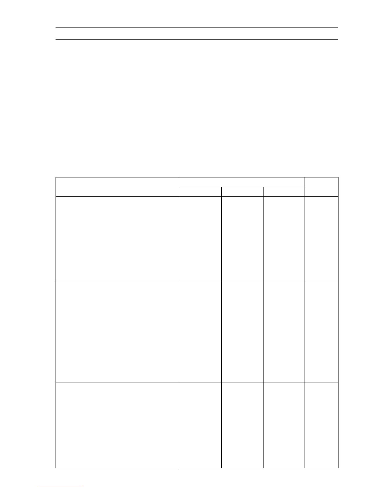
PERIODIC MAINTENANCE 2-5
Torque and Locking Agent
Tighten all bolts and nuts to the proper torque using an accurate torque wrench. If insufficiently
tightened, a bolt or nut may becomedamaged, strip an internalthread, or break and then fall out. The
following table lists the tighteningtorque for the major bolts and nuts, and the parts requiring use of a
non-permanent locking agent or silicone grease etc.
When checking the tightening torque of the bolts and nuts, first loosen the bolt or nut by half a turn
and then tighten to specified torque.
Letters used in the "Remarks" column mean:
AL: Tighten the two clamp bolts alternately two times to ensure even tightening torque.
G: Apply grease.
L: Apply a non-permanent locking agent.
Lh: Left-hand Threads
MO: Apply molybdenum disulfide oil.
(mixture of engine oil and molybdenum disulfide grease with a weight ratio 10 : 1)
R: Replacement Parts
S: Follow the specified tightening sequence.
Si: Apply silicone grease (ex. PBC grease).
Torque
Fastener
N·m kgf·m ft·lb
Remarks
Fuel System
Throttle Pulley Cover Bolt 3.4 0.35 30 in·lb
Throttle Cable Bolts
3.5 0.36 31 in·lb
Hot Starter Plunger Cap Bolt
1.0 0.10 9in·lb
Air Cleaner Element Wing Bolt – – –
Hand
Tighten
Air Cleaner Duct Nuts 3.0 0.30 27 in·lb
Air Cleaner Duct Bolt 7.1 0.72 63 in·lb
Air Cleaner Housing Bolts 9.8 1.0 87 in·lb
Cooling System
Water Pump Cover Bolts (L = 30, 65
mm)
9.8 1.0 87 in·lb
Water Pump Cover Bolts (L = 55 mm)
9.8 1.0 87 in·lb L
Coolant Drain Bolt 7.0 0.71 62 in·lb
Water Pump Impeller Bolt 7.0 0.71 62 in·lb
Water Hose Clamp Screws
3.0 0.31 27 in·lb
Water Pipe Bolt 9.8 1.0 87 in·lb
Radiator Mounting Bolts 9.8 1.0 87 in·lb
Radiator Screen Bolts 9.8 1.0 87 in·lb
Radiator Shroud Bolts 9.8 1.0 87 in·lb
Engine Top End
Auto-Decompressor Bolt 12 1.2 106 in·lb
Cylinder Head Cover Bolts 9.8 1.0 87 in·lb
Camshaft Cap Bolts 9.8 1.0 87 in·lb S, MO
Cylinder Head Bolts (M10) 49 5.0 36 S, MO
Cylinder Head Bolts (M6) 12 1.2 106 in·lb S
Plug 20 2.0 15 L
Decompressor Plug Plate Bolt 9.8 1.0 87 in·lb
Carburetor Holder Clamp Screw 2.0 0.20 18 in·lb

2-6 PERIODIC MAINTENANCE
Torque and Locking Agent
Torque
Fastener
N·m
kgf·m ft·lb
Remarks
Carburetor Clamp Screw 2.0 0.20 18 in·lb
Cylinder Bolt 12 1.2 106 in·lb S
Camshaft Chain Tensioner Cap Bolt 20 2.0 15
Camshaft Chain Tensioner Mounting
Bolts
9.8 1.0 87 in·lb
Lower Camshaft Chain Guide Bolt 9.8 1.0 87 in·lb
Rear Camshaft Chain Guide Bolt 15 1.5 11
Exhaust Pipe Cover Screws
12 1.2 106 in·lb
Exhaust Pipe Holder Nuts 15 1.5 11
S
Muffler M ounting Bolts 21 2.1 15 S
Muffler Clamp Bolt 11 1.1 97 in·lb S
Clutch
Clutch Cover Bolts 9.8 1.0 87 in·lb
Right Engine Cover Bolts 9.8 1.0 87 in·lb
Clutch Spring Bolts 9.8 1.0 87 in·lb
Clutch Hub Nut 98 10 72 R
Oil Filler Plug 5.0 0.51 44 in·lb
Primary Gear Nut 98 10 72 Lh, R
Engine Lubrication System
Breather Fitting 15 1.5 11 L
Oil Pump Mounting Bolts 7.0 0.71 62 in·lb L
Oil Pump Idle Gear Shaft Screws 5.9 0.60 52 in·lb L
Oil Filter Cap Bolts
9.8 1.0 87 in·lb
Piston Oil Nozzle
2.9 0.30 26 in·lb
Engine Oil Drain Bolt 20 2.0 15
Engine Removal/Installation
Upper Engine Mounting Bolts (M10) 49 5.0 36 S
Upper Engine Bracket Bolts (M8) 29 3.0 21 S
Middle Engine Mounting Nut (M10) 49 5.0 36 R, S
Middle Engine Bracket Nuts (M8) 29 3.0 21 R, S
Lower Engine Mounting Nut (M10) 49 5.0 36 R, S
Swingarm Pivot Shaft N ut 98 10 72 R, S
Crankshaft/Transmission
Crankcase Bolts 50 mm (2.0 in.) 9.8 1.0 87 in·lb S
Crankcase Bolts 60
mm (2.4 in.)
9.8 1.0 87 in·lb
S
Crankcase Bolts 65 mm (2.6 in.)
9.8 1.0 87 in·lb
S
Crankcase Bolts 70 mm (2.8 in.) 9.8 1.0 87 in·lb S
Crankcase Bearing Retainer Bolts 15 1.5 11 L
Piston Oil Nozzle 2.9 0.30 26 in·lb
Reed Valve Screws 7.0 0.71 62 in·lb
Primary Gear Nut 98 10 72 Lh, R
Kick Pedal Bolt 25 2.5 18 L
Kick Ratchet Guide Bolt 8.8 0.90 78 in·lb L

PERIODIC MAINTENANCE 2-7
Torque and Locking Agent
Torque
Fastener
N·m kgf·m ft·lb
Remarks
Ratchet Plate Bolt (Front) 9.8 1.0 87 in·lb L, S
Ratchet Plate Bolt (Rear) 15 1.5 11 L, S
Shift Drum Cam Bolt 24 2.4 18 L
Gear Positioning Lever Nut 8.8 0.90 78 in·lb
Shift Pedal Bolt 9.8 1.0 87 in·lb
Wheels/Tires
Spoke Nipples
Not Less
Than 2.2
Not Less
Than 0.22
Not Less
Than 19 in·lb
Front Axle Nut 79 8.1 58
Front Axle Clamp Bolts 20 2.0 15 AL
Rear Axle Nut 108 11.0 80
Final Drive
Rear Sprocket Nuts 34 3.5 25 R
Engine Sprocket C over Bolts 4.9 0.50 43 in·lb
Brakes
Front Brake Reservoir Cap Screws 1.5 0.15 13 in·lb
Front Master Cylinder Clamp Bolts 8.8 0.90 78 in·lb S
Brake Lever Pivot Bolt 5.9 0.60 52 in·lb Si
Brake Lever Pivot Bolt Locknut 5.9 0.60 52 in·lb
Brake Hose Banjo Bolts 25 2.5 18
Brake Hose Clamp Mounting Bolt 3.0 0.31 27 in·lb
Front Brake Disc Mounting Bolts 9.8 1.0 87 in·lb L
Caliper Bleed Valve 7.8 0.80 69 in·lb
Front Brake Pad Pin 17 1.7 13
Front Caliper Mounting Bolts 25 2.5 18
Rear Brake Reservoir Cap Screws 1.5 0.15 13 in·lb
Rear Master Cylinder Mounting Bolts 9.8 1.0 87 in·lb
Rear Master Cylinder Push Rod Locknut 17 1.7 13
Brake Pedal Bolt 25 2.5 18 L, G
Rear Brake Disc Mounting Bolts 23 2.3 17 L
Rear Brake Pad Pin Plug 2.5 0.25 22 in·lb
Rear Brake Pad Pin 17 1.7 13
Rear Caliper Holder Shaft 27 2.8 20 Si
Suspension
Front Fork Cylinder Unit 34 3.5 25
Front Fork Clamp Bolts (Lower) 20 2.0 15 AL
Front Fork Clamp Bolts (Upper) 20 2.0 15 AL, L
Front Fork Adjuster Assembly Locknut 22 2.2 16
Front Fork Base Valve Assembly 30 3.1 22
Front Fork A djuster Assembly 69 7.0 51 L
Pressure Relief Screws 1.3 0.13 12 in·lb
Swingarm Pivot Shaft Nut 98 10 72 R
Rocker Arm Pivot Nut 59 6.0 44 R
2-8 PERIODIC MAINTENANCE
Torque and Locking Agent
Torque
Fastener
N·m
kgf·m ft·lb
Remarks
Tie-Rod Mounting Nuts 59 6.0 44 R
Rear Shock Absorber Mounting Nut
(Upper)
39 4.0 29 R
Rear Shock Absorber Mounting Nut
(Lower)
34 3.5 25 R
Rear Shock Absorber Spring Locknut 45 4.6 33
Piston Rod Locknut 37 3.8 27 R
Gas R eservoir Damping Adjuster
Assembly
29 3.0 21
Steering
Handlebar Clamp Bolts 25 2.5 18 AL
Steering Stem Head Nut 98 10 72
Steering Stem Nut 4.9 0.50 43 in·lb
Front Fork Clamp Bolts (Upper ) 20 2.0 15 AL, L
Front Fork Clamp Bolts (Lower) 20 2.0 15 AL
Frame
Rear Frame Mounting Bolts 34 3.5 25
Footpeg Bracket Bolts (Upper) 54 5.5 40 L
Electrical System
C.D.I. Unit Mounting B olts 9.8 1.0 87 in·lb
Spark Plug 13 1.3 115 in·lb
Timing Inspection Cap 3.9 0.40 35 in·lb
Flywheel Cap 4.9 0.50 43 in·lb
Magneto Cover Bolts 9.8 1.0 87 in·lb
Flywheel Nut 49 5.0 36
Stator Bolts 7.0 0.71 62 in·lb L
Crankshaft Sensor Bolts 7.0 0.71 62 in·lb L
Neutral Switch 12 1.2 106 in·lb
Neutral Switch Terminal Screw
1.5 0.15 13 in·lb
Basic Torque for General Fasteners
Threads
diameter
Torque
(mm) N·m kgf·m ft·lb
5 3.4 ∼ 4.9 0.35 ∼ 0.50 30 ∼ 43 in·lb
6 5.9 ∼ 7.8 0.60 ∼ 0.80 52 ∼ 69 in·lb
8 14 ∼ 19 1.4 ∼ 1.9 10.0 ∼ 13.5
10 25 ∼ 34 2.6 ∼ 3.5 19.0 ∼ 25
12 44 ∼ 61 4.5 ∼ 6.2 33 ∼ 45
14 73 ∼ 98 7.4 ∼ 10.0 54 ∼ 72
16 115 ∼ 155 11.5 ∼ 16.0 83 ∼ 115
18 165 ∼ 225 17.0 ∼ 23.0 125 ∼ 165
20 225 ∼ 325 23 ∼ 33 165 ∼ 240

PERIODIC MAINTENANCE 2-9
Specifications
Item Standard Service Limit
Fuel System
Throttle Grip Free Play 2 ∼ 3 mm (0.08 ∼ 0.12 in.) –––
Hot Starter Lever Free Play 0.5 ∼ 1.0 mm (0.02 ∼ 0.04 in.) –––
Idle Speed 1 950 ±50 r/min (rpm) –––
Air Cleaner Element O il High quality foam air filter oil –––
Cooling System
Coolant:
Type (recommended) Permanent type antifreeze
–––
Color Green –––
Mixed Ratio Soft water 50%, antifreeze 50% –––
Freezing Point –35°C (–31°F) –––
Total Amount 1.2 L (1.3 US qt.) –––
Engine Top End
Valve Clearance:
Exhaust 0.17 ∼ 0.22 mm (0.0067 ∼ 0.0087 in.) –––
Inlet 0.10 ∼ 0.15 mm (0.0039 ∼ 0.0059 in.) –––
Cylinder Head Warp ––– 0.05 mm
(0.0020 in.)
Cylinder Inside Diameter (see text) 77.000 ∼ 77.012 mm 77.10 mm
(3.0315 ∼ 3.0320 in.) (3.035 in.)
Piston/Cylinder Clearance 0.041 ∼ 0.068 mm –––
(0.0016 ∼ 0.0027 in.)
Clutch
Clutch Lever Free Play 8 ∼ 13 mm (0.3 ∼ 0.5 in.) –––
Friction Plate Thickness 2.72 ∼ 2.88 mm (0.107 ∼ 0.113 in.) 2.5 mm (0.10 in.)
Friction Plate Warp 0.15 mm (0.0059 in.) or less 0.3 mm (0.012 in.)
Steel Plate Warp 0.15 mm (0.0059 in.) or less 0.3 mm (0.012 in.)
Engine Lubrication System
Engine Oil:
Grade Castrol “POWER1 R4 Racing” 5W-40
or API SG, SH, SJ or SL with JASO
MA, MA1 or MA2
–––
Viscosity SAE 10W-30, 10W-40, or 10W-50 –––
Capacity
0.75 L (0.79 U S qt.) (when filter is not
removed)
–––
0.80 L (0.85 US qt.) (when filter is
remove)
1.00 L (1.06 US qt.) (when engine is
completely dry)
Crankshaft/Transmission
0.25 ∼ 0.35 mm 0.6 mm
Connecting Rod Big End Side
Clearance
(0.0098 ∼ 0.0138 in.) (0.02 in.)

2-10 PERIODIC MAINTENA NCE
Specifications
Item Standard Service Limit
Wheels/Tires
Rim Runout (with tire installed):
Axial TIR 1.0 mm (0.039 in.) or less TIR 2.0 mm
(0.079 in.)
Radial TIR 1.0 mm (0.039 in.) or less TIR 2.0 mm
(0.079 in.)
Tires Air Pressure (Front/Rear) 100 kPa (1.00 kgf/cm², 14 psi) –––
Standard Tire:
Front:
Size 80/100-21 51M –––
Make BRIDGESTONE –––
Type M403, Tube –––
Rear:
Size 100/90-19 57M –––
Make BRIDGESTONE –––
Type M404, Tube –––
Final Drive
DriveChainSlack 52 ∼ 58 mm (2.0 ∼ 2.3 in.) –––
Drive Chain 20-link Length 317.5 ∼ 318.2 mm (12.50 ∼ 12.53 in.) 323 mm (12.7 in.)
Rear Sprocket Warp (Runout) TIR 0.4 mm (0.016 in.) or less TIR 0.5 mm
(0.020 in.)
Brakes
Brake Lever Free Play Adjustable (to suit rider) –––
Brake Fluid Type:
Front DOT3 or DOT4 –––
Rear DOT3 or DOT4 –––
Brake Pad Lining Thickness:
Front 4.0 mm (0.16 in.) 1 mm (0.04 in.)
Rear 6.4 mm (0.25 in.) 1 mm (0.04 in.)
Suspension
Fork Oil:
Viscosity SHOWA SS-19 or equivalanet S AE 5W –––
Capacity (per unit):
Cylinder Unit 180 mL (6.09 US oz.)
–––
Cylinder Unit Oil Level 42 ∼ 49 mm (1.7 ∼ 1.9 in.) –––
Outer Tube 369 ±2.5 mL (12.5 ±0.085 US oz.) 307 ∼ 408 mL
(10.4 ∼ 13.8 US oz.)
Rear Shock Absorber Oil:
Viscosity SHOWA SS-25 or equivalent SAE 2.5W –––
Capacity Approximately 395 mL (13.4 US oz.) –––
Electrical System
Spark Plug Gap 0.7 ∼ 0.8 mm (0.026 ∼ 0.031 in.) –––
PERIODIC MAINTENANCE 2-11
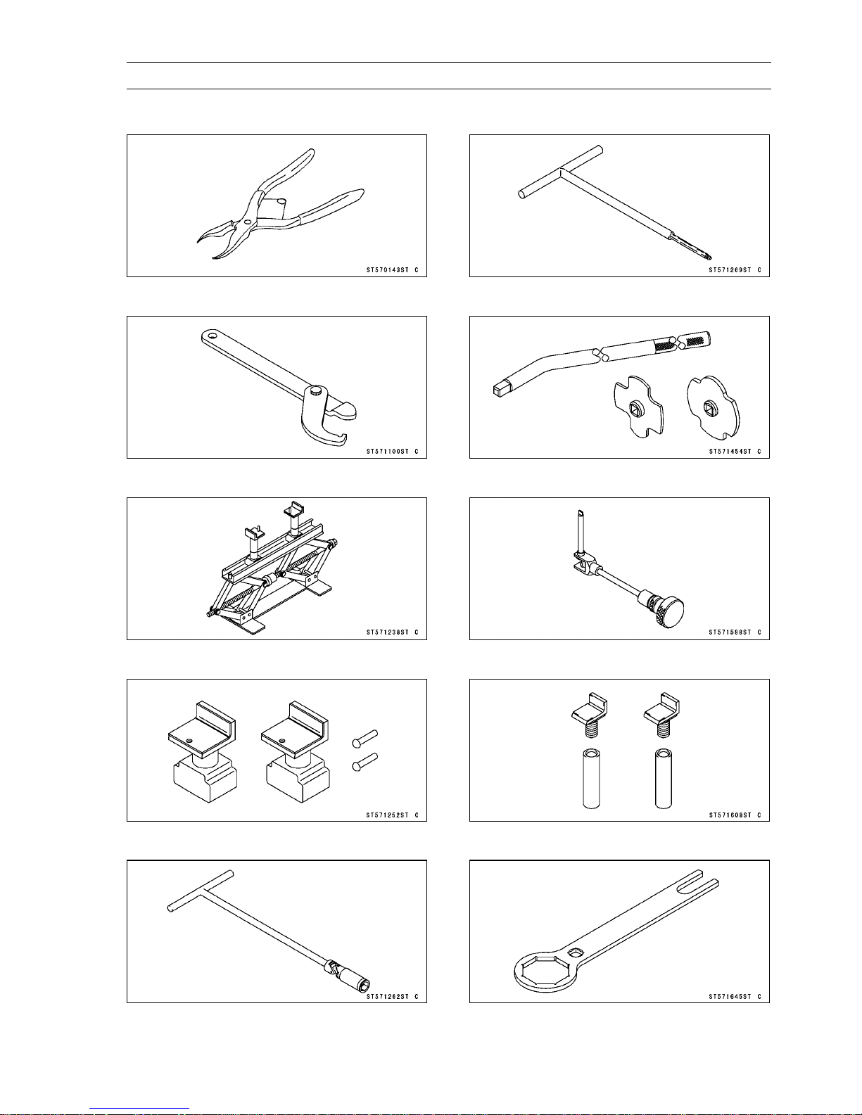
Special Tools
Inside Circlip Pliers:
57001-143
Steering Stem Nut Wrench:
57001-1100
Jack:
57001-1238
Attachment Jack:
57001-1252
Spark Plug Wrench, Hex 16:
57001-1262
Carburetor Drain Plug Wrench, Hex 3:
57001-1269
Filler Cap Driver:
57001-1454
Pilot Screw Adjuster, D:
57001-1588
Jack Attachment:
57001-1608
Top Plug Wrench, 50 mm:
57001-1645
2-12 PERIODIC MAINTENA NCE
Periodic Maintenance Procedures
Fuel System
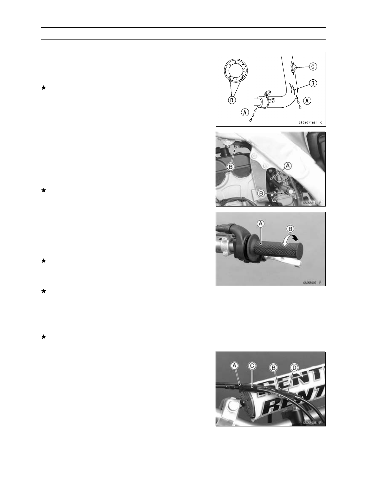
Fuel Hose and Connection Inspection
○
If the motorcycle is not properly handled, the inside the
fuel line can cause fuel to leak [A].
•
Check the fuel hose.
Replace thefuelhose ifany fraying, cracks [B], bulges [C]
or ozone cracks [D] are noticed.
•
Check that the hose [A] are securely connected and
clamps [B] are tightened correctly.
•
Routethehoseaccording to Cable, Wire, and HoseRouting section in the Appendix chapter.
○
Avoid sharp bending, kinking, flattening or twisting, and
route the fuel hosewith a minimum of bending so that the
fuel flow will not be obstructed.
Replace the hose if it has been sharply bent or kinked.
ThrottleGrip(ThrottleCable)FreePlayInspection
•
Check throttle grip free play by lightly turning the throttle
grip [A] back and forth [B].
Throttle Grip Free Play
Standard: 2 ∼ 3 mm (0.08 ∼ 0.12 in.)
If the free play is improper, adjust the throttle cable.
•
Checkthatthethrottlegrip moves smoothly from full open
to close, and the throttle closes quickly and completely in
all steering positions by the return spring.
Ifthe throttlegrip does not returnproperly,check the throttle cable routing, grip free play, and cable damage. Then
lubricate the throttle cable.
•
Run t he engine at the idle speed, and turn the handlebar
allthe wayto the rightand leftto ensurethatthe idlespeed
does not change.
If the idle speed increase, check the throttle cable free
play and the cable routing.
Throttle G rip (Throttle Cable) Free Play
Adjustment
•
Loosen the locknuts [A] [B] at theupper end ofthe throttle
cable.
•
Screw both throttle cable adjuster [C][D] togive the throttle grip plenty of play.
•
Turn out the decelerator adjuster [C] until there is no play
when the t hrottle grip is completely closed.
•
Tighten the locknut [A].
•
Turn the accelerator cable adjuster [D] until 2 ∼ 3mm
(0.08 ∼ 0.12 in.) of throttle grip play is obtained.
•
Tighten the locknut [B].
 Loading...