

Page 1
BPP 3000/42
BPP 4000/48
BPP 4500/50
Deutsch 5
English 13
Français 21
Italiano 29
Nederlands 37
Español 45
Português 53
Ελληνικά 61
Українська 70
Register and win!
www.kaercher.com
59644630 10/12
Page 2

2
Page 3
3
Page 4
6.997-350.0 / 6.997-349.0
6.997-360.0 6.997-345.0 / 6.997-342.0 6.997-341.0
6.997-348.0 6.997-347.0 / 6.997-346.0
6.997-343.0 / 6.997-344.0
6.997-356.0
4
6.997-359.0
6.997-355.0 6.997-417.0
6.997-358.0 / 6.997-340.0
Page 5
Inhaltsverzeichnis
Inhaltsverzeichnis. . . . . . . . DE . . .1
Allgemeine Hinweise . . . . . DE . . .1
Sicherheitshinweise . . . . . . DE . . .2
Bedienung . . . . . . . . . . . . . DE . . .3
Pflege, Wartung . . . . . . . . . DE . . .4
Transport . . . . . . . . . . . . . . DE . . .4
Lagerung . . . . . . . . . . . . . . DE . . .4
Sonderzubehör. . . . . . . . . . DE . . .5
Hilfe bei Störungen. . . . . . . DE . . .6
Technische Daten. . . . . . . . DE . . .8
Allgemeine Hinweise
Sehr geehrter Kunde,
Lesen Sie vor der ersten Benut-
zung Ihres Gerätes diese Originalbetriebsanleitung, handeln Sie danach
und bewahren Sie diese für späteren Gebrauch oder für Nachbesitzer auf.
Bestimmungsgemäße Verwendung
Dieses Gerät wurde für den privaten Gebrauch entwickelt und ist nicht für die Beanspruchungen des gewerblichen Einsatzes
vorgesehen.
Der Hersteller haftet nicht für eventuelle
Schäden, die durch nicht bestimmungsgemäßen Gebrauch oder falsche Bedienung
verursacht werden.
Das Gerät ist zum Einsatz als Hauswasserwerk bestimmt.
Beim Einsatz der Pumpe zur Druckverstärkung darf der max. Zuleitungsdruck von 1,0
bar (Pumpeneintritt) nicht überschritten
werden.
Zugelassene Förderflüssigkeiten:
Brauchwasser
Brunnenwasser
Quellwasser
Regenwasser
Schwimmbadwasser (bestimmungsge-
mäße Dosierung der Additive vorausgesetzt)
몇 Warnung
Nicht gefördert werden dürfen ätzende,
leicht brennbare oder explosive Stoffe
(z.B. Benzin, Petroleum, Nitroverdünnung), Fette, Öle, Salzwasser und Abwasser aus Toilettenanlagen und
verschlammtes Wasser, das eine geringere Fließfähigkeit als Wasser hat. Die
Temperatur der geförderten Flüssigkeit
darf 35°C nicht überschreiten.
Umweltschutz
Die Verpackungsmaterialien sind recyclebar. Bitte werfen Sie die Verpackungen nicht in den Hausmüll,
sondern führen Sie diese einer Wiederverwertung zu.
Altgeräte enthalten wertvolle recyclingfähige Materialien, die einer
Verwertung zugeführt werden sollten. Bitte entsorgen Sie Altgeräte deshalb
über geeignete Sammelsysteme.
Hinweise zu Inhaltsstoffen (REACH)
Aktuelle Informationen zu Inhaltsstoffen finden Sie unter:
www.kaercher.de/REACH
Garantie
In jedem Land gelten die von unserer zuständigen Vertriebsgesellschaft herausgegebenen Garantiebedingungen. Etwaige
Störungen an Ihrem Gerät beseitigen wir
innerhalb der Garantiefrist kostenlos, sofern ein Material- oder Herstellungsfehler
die Ursache sein sollte. Im Garantiefall
wenden Sie sich bitte mit Kaufbeleg an Ihren Händler oder die nächste autorisierte
Kundendienststelle.
Symbole in der Betriebsanleitung
Gefahr
Für eine unmittelbar drohende Gefahr, die
zu schweren Körperverletzungen oder zum
Tod führt.
– 1
5DE
Page 6

몇 Warnung
Für eine möglicherweise gefährliche Situation, die zu schweren Körperverletzungen
oder zum Tod führen könnte.
Vorsicht
Für eine möglicherweise gefährliche Situation, die zu leichten Verletzungen oder zu
Sachschäden führen kann.
Sicherheitshinweise
Lebensgefahr
Bei Nichtbeachtung der Sicherheitshinweise besteht Lebensgefahr durch elektrischen Strom!
Anschlussleitung mit Netzstecker vor
jedem Betrieb auf Schäden prüfen. Beschädigte Anschlussleitung unverzüglich durch autorisierten Kundendienst/
Elektro-Fachkraft austauschen lassen.
Alle elektrischen Steckerverbindungen
sind im überflutungssicheren Bereich
anzubringen.
Nicht am Netzanschlusskabel, sondern
am Stecker ziehen, um das Gerät vom
Netz zu trennen.
Das Netzanschlusskabel nicht über
scharfe Kanten ziehen und nicht einquetschen.
Das Gerät stand- und überflutungssi-
cher aufstellen.
Die angegebene Spannung auf dem
Typenschild muss mit der Spannung
der Stromquelle übereinstimmen.
Um Gefährdungen zu vermeiden, dür-
fen Reparaturen und der Einbau von
Ersatzteilen nur vom autorisierten Kundendienst durchgeführt werden.
Bei fehlender Wasserzufuhr schaltet
die Pumpe nicht ab. Das Wasser in der
Pumpe erhitzt sich und kann bei Austritt
zu Verletzungen führen!
Pumpe max. 3 Minuten in diesem Betriebszustand betreiben.
Tipp: Trockenlaufsicherung (6.997-
355.0), Schwimmerschalter (6.997-
356.0) optional erhältlich!
Die Pumpe darf nicht als Tauchpumpe
verwendet werden.
Bei Verwendung der Pumpe an
Schwimmbecken, Gartenteichen oder
Springbrunnen einen Mindestabstand
von 2m einhalten und Gerät gegen Abrutschen ins Wasser sichern.
Elektrische Schutzeinrichtungen be-
achten:
Pumpen dürfen an Schwimmbecken,
Gartenteichen und Springbrunnen nur
über einen Fehlerstromschutzschalter
mit einem Nennfehlerstrom von max.
30mA betrieben werden. Wenn sich
Personen im Schwimmbecken oder
Gartenteich befinden, darf die Pumpe
nicht betrieben werden.
Aus Sicherheitsgründen empfehlen wir
grundsätzlich, das Gerät über einen
Fehlerstromschutzschalter (max.
30mA) zu betreiben.
Der elektrische Anschluss darf nur von
einer Elektrofachkraft vorgenommen
werden. Die nationalen Bestimmungen
hierzu sind unbedingt zu beachten!
In Österreich müssen Pumpen zum
Gebrauch an Schwimmbecken und
Gartenteichen, die mit einer festen Anschlussleitung ausgestattet sind, nach
ÖVE B/EN 60555 Teil 1 bis 3, über einen ÖVE-geprüften Trenn-Transformator gespeist werden, wobei die
Nennspannung sekundär 230V nicht
überschreiten darf.
Das Gerät kann von Kindern ab acht
Jahren und von Personen mit verringerten physischen, sensorischen oder
geistigen Fähigkeiten oder Mangel an
Erfahrung und Wissen benutzt werden,
wenn sie beaufsichtigt oder bezüglich
des sicheren Gebrauchs des Gerätes
unterwiesen wurden und die daraus resultierenden Gefahren verstehen.
Kinder beaufsichtigen, um sicherzustel-
len, dass sie nicht mit dem Gerät spielen.
6 DE
– 2
Page 7

Voraussetzungen für die Standsi-
cherheit
Vorsicht
Vor allen Tätigkeiten mit oder am Gerät
Standsicherheit herstellen, um Unfälle oder
Beschädigungen durch Umfallen des Geräts zu vermeiden.
– Die Standsicherheit des Gerätes ist ge-
währleistet wenn es auf einer ebenen
Fläche abgestellt wird.
Bedienung
Vor Inbetriebnahme der Pumpe sind unbedingt die Sicherheitshinweise zu beachten!
Gerätebeschreibung
1 Netzanschlusskabel mit Stecker
2 Anschluss G1 (33,3 mm) Saugleitung
3 Anschluss G1 (33,3 mm) Druckleitung
4 Einfüllstutzen mit Vorfilter
5 Druckanzeige
6 Ablassöffnung
7 Rückschlagventil
Vorbereiten
Abbildung
Vor Inbetriebnahme Druck der Luftfül-
lung im Speicherkessel prüfen. Ggf. im
ausgeschalteten / drucklosen Zustand
auf 2,0 bar nachfüllen.
Abbildung
Gerät gegen Verrutschen sichern (evtl.
verschrauben).
Abbildung
Rückschlagventil montieren.
Vakuumfesten Saugschlauch mit integ-
riertem Rückflussstop an Saugseite anschließen.
(als Sonderzubehör erhältlich)
Druckseite zur Geräuschreduzierung
über flexiblen Schlauch mit Druckleitung verbinden.
Abbildung
Um die spätere Entleerung und Druck-
entlastung des Systems zu vereinfachen, empfehlen wir die Montage eines
Ablasshahns zwischen Pumpe und
Saugschlauch / Rückschlagventil.
(nicht im Lieferumfang enthalten)
Abbildung
Deckel am Einfüllstutzen abschrauben
und Wasser bis zum Überlaufen einfüllen.
Deckel fest auf den Einfüllstutzen
schrauben.
Vorhandene Absperrventile in der
Druckleitung öffnen.
Hinweis: Geringste Undichtigkeiten führen
zu Fehlfunktion.
Betrieb
Netzstecker in Steckdose stecken.
몇 Achtung
Pumpe läuft sofort an. Warten bis Pumpe
ansaugt und gleichmäßig fördert, dann Absperrventile in Druckleitung schließen.
Nach Erreichen des Abschaltdrucks schaltet der Druckschalter den Motor aus. Der
Speicherkessel ist jetzt gefüllt, das Hauswasserwerk ist betriebsbereit.
Bei fehlender Wasserzufuhr wird der Abschaltdruck nicht erreicht, der Druckschalter kann das Gerät nicht mehr abschalten,
das Wasser im Pumpenkopf erhitzt sich dadurch bis zur Gerätebeschädigung. In den
Geräten BPP 4000/48 und BPP 4500/50
wird die Stromzufuhr bei Überhitzung durch
einen Thermoschalter unterbrochen. Nach
Abkühlung wird die Stromzufuhr wieder hegestellt.
Wir empfehlen zur regulären Absicherung
des Wassermangels den Einsatz einer
Trockenlaufsicherung.
몇 Achtung
System steht unter Druck!
(Druck siehe Kapitel technische Daten)
Betrieb beenden
Netzstecker aus Steckdose ziehen.
– 3
7DE
Page 8

Pflege, Wartung
Transport
Gefahr
Vor allen Wartungs- und Reinigungsarbeiten Netzstecker ziehen.
System steht unter Druck!
Vor dem Öffnen von Einfüll- oder Ablassdeckel bzw. vor dem Trennen von Leitungsverbindungen, Absperrventil auf
Druckseite öffnen und System über Ablasshahn (im Fachhandel erhältlich) entleeren.
Pflege
Abbildung
Vorfilter regelmäßig auf Verschmutzun-
gen kontrollieren. Bei sichtbaren Verschmutzungen wie folgt vorgehen:
Deckel am Einfüllstutzen abschrauben.
Vorfilter entnehmen und unter fließen-
dem Wasser reinigen.
Wartung
Abbildung
Druck der Luftfüllung im Speicherkessel
jährlich prüfen. Ggf. im ausgeschalteten
/ drucklosen Zustand auf 2,0 bar nachfüllen (Gerät ausstecken, Wasserhahn
öffnen).
Vorsicht
Um Unfälle oder Verletzungen zu vermeiden beim Transport das Gewicht des Gerätes beachten (siehe technische Daten).
Transport von Hand
Gerät am Tragegriff hochheben und tra-
gen.
Transport in Fahrzeugen
Gerät gegen Verrutschen und Kippen
sichern.
Lagerung
Vorsicht
Um Unfälle oder Verletzungen zu vermeiden bei der Auswahl des Lagerortes das
Gewicht des Gerätes beachten (siehe technische Daten).
Gerät aufbewahren
Gerät an einem frostfreien Ort aufbe-
wahren.
8 DE
– 4
Page 9

Sonderzubehör
Die Abbildungen der nachfolgend aufgeführten Sonderzubehöre finden Sie auf Seite 4
dieser Anleitung.
6.997-350.0 Sauggarnitur 3,5m Komplett anschlussfertiger, vakuumfester Saug-
6.997-349.0 Sauggarnitur 7,0m
6.997-348.0 Saugschlauch 3,5m Komplett anschlussfertiger, vakuumfester Saug-
schlauch mit Saugfilter und Rückflussstopp. Auch
als Verlängerung des Saugschlauchs verwendbar.
3/4“ (19mm) Schlauch mit G1 (33,3mm) Anschlussgewinde.
schlauch zum Direktanschluss an die Pumpe. Zur
Verlängerung der Sauggarnitur oder zur Verwendung mit Saugfiltern. 3/4“ (19mm) Schlauch mit G1
(33,3mm) Anschlussgewinde.
6.997-347.0 Saugschlauch Meterware 3/4“ (19
mm), 25 m
6.997-346.0 Saugschlauch Meterware 1“ (25,4
mm), 25 m
6.997-360.0 Saugschlauch für
Rammbrunnen und
Rohrleitungen
6.997-345.0 Saugfilter Basic 3/4“
(19mm)
6.997-342.0 Saugfilter Basic 1“
(25,4mm)
6.997-341.0 Saugfilter Premium Zum Anschluss an die Saugschlauch-Meterware.
6.997-343.0 Vorfilter (Durchfluss
bis 3000 l/h)
6.997-344.0 Vorfilter (Durchfluss
bis 6000 l/h)
Vakuumfester Spiralschlauch zum Zuschneiden
von individuellen Schlauchlängen. Kombiniert mit
Anschlussstücken und Saugfilter als individuelle
Sauggarnitur einsetzbar.
Vakuumfester Spiralschlauch zum Anschluss an
der Saugseite der Pumpe. 1“(25,4mm) Schlauch
mit beidseitigem G1(33,3mm) Anschlussgewinde.
Achtung: Der Saugschlauch darf nicht als Druckschlauch eingesetzt werden.
Zum Anschluss an die Saugschlauch-Meterware.
Der Rückflussstopp verkürzt die Wiederansaugzeit.
(Inklusive Schlauchklemmen)
Der Rückflussstopp verkürzt die Wiederansaugzeit.
(Inklusive Schlauchklemmen). Robuste MetallKunststoff-Ausführung. Passend für 3/4“ (19mm)
oder 1“ (25,4mm) Schläuche.
Pumpenvorfilter zum Schutz der Pumpe vor groben
Schmutzpartikeln oder Sand. Der Filtereinsatz
kann zur Reinigung entnommen werden. Mit G1
(33,3mm) Anschlussgewinde.
– 5
9DE
Page 10

6.997-359.0 Pumpenanschlussstück G1 (33,3mm)
Passend für 3/4“(19mm) oder 1“(25,4mm) Schläuche. Mit G1 (33,3mm) Anschlussgewinde. Inklusive
Rückschlagventil, Flachdichtung und Schlauchklemme. Bei Verwendung für Gartenpumpen die
Flachdichtung einsetzen.
6.997-358.0 Anschlusssatz Basic G1 (33,3mm)
6.997-340.0 Anschlusssatz Premium G1 (33,3mm)
6.997-356.0 Schwimmerschalter Schaltet die Pumpe in Abhängigkeit vom Wasser-
6.997-355.0 Trockenlaufsicherung
6.997-417.0 Druckausgleichsschlauch 3/4“
(19mm), 1m
Zum Anschluss von 1/2“ (12,7mm) Wasserschläuchen an Pumpen mit G1 (33,3mm) Anschlussgewinde.
Zum Anschluss von 3/4“ (25,4mm) Wasserschläuchen an Pumpen mit G1 (33,3mm) Anschlussgewinde. Für erhöhten Wasserdurchfluss.
stand des Wasserreservoirs automatisch ein und
aus. Mit 10m Spezial-Anschlusskabel.
Läuft kein Wasser durch die Pumpe, schützt die
Trockenlaufsicherung die Pumpe vor Schäden und
schaltet diese automatisch ab. Mit G1 (33,3mm)
Anschlussgewinde.
Anschlussschlauch zum Druckausgleich in der
Hauswasserinstallation. Zum Anschluss der Pumpe an starre Rohrleitungssysteme. Zudem verhindert internes Speichervolumen im Schlauch
häufiges Ein- und Ausschalten der Pumpe.
Hilfe bei Störungen
Gefahr
Um Gefährdungen zu vermeiden, dürfen Reparaturen und der Einbau von Ersatzteilen
nur vom autorisierten Kundendienst durchgeführt werden.
Vor allen Arbeiten am Gerät, Gerät ausschalten und Netzstecker ziehen.
Störung Ursache Behebung
Pumpe läuft
aber fördert
nicht
Pumpe läuft
nicht an oder
bleibt während
des Betriebs
plötzlich stehen
10 DE
Luft in der Pumpe siehe Kapitel „Vorbereiten“ Abb. E
Luft kann an der Druckseite
nicht entweichen
Stromversorgung unterbrochen
Thermoschutzschalter im Motor hat die Pumpe wegen
Überhitzung des Motors abgeschaltet.
Entnahmestelle an der Druckseite öffnen
Sicherungen und elektrische Verbindungen prüfen.
Netzstecker ziehen, Pumpe abkühlen
lassen, Ansaugbereich reinigen,
Trockenlauf verhindern.
– 6
Page 11

Störung Ursache Behebung
Pumpe schaltet sich selbst
aus und auch
wieder ein
(BPP 4000/48
und BPP 4500/
50)
Motor läuft
nach dem Abschalten sofort
wieder an
Förderleistung
nimmt ab oder
ist zu gering
Vibrierendes
Geräusch bei
Wasserentnahme
Thermoschutzsicherung hat
die Pumpe zum Schutz vor
Überhitzung abgeschaltet
bzw. nach Abkühlung wieder
eingeschaltet.
Druck im System geht verloren Verbindungen inklusive Dichtungen
Luftdruck im Speicherkessel
ist zu niedrig.
Rückschlagventil schließt nicht
richtig
Membran im Druckkessel defekt
Saugfilter oder Rückschlagventil verunreinigt
Förderleistung der Pumpe ist
abhängig von der Förderhöhe
und der angeschlossenen Peripherie
Vorfilter verunreinigt Vorfilter entnehmen und unter fließen-
Membran im Druckkessel vibriert
Um einer Wiederholung vorzubeugen
sollte das System auf Leckagen überprüft und abgedichtet werden.
überprüfen und Wasseraustritt kontrollieren.
Geringste Undichtheiten wirken sich
auf den Betrieb aus.
Speicherkessel mit 2,0 bar befüllen.
Siehe Kapitel „Wartung“ Abb. A
Rückschlagventil auf Saugseite überprüfen.
Membran erneuern
Saugfilter bzw. Rückschlagventil reinigen
Max. Förderhöhe beachten, siehe
technische Daten, ggf. anderen
Schlauchdurchmesser oder andere
Schlauchlänge wählen.
dem Wasser reinigen.
Betriebsbedingtes Geräusch das
durch Reduzieren des Drucks der
Luftfüllung im Speicherkessel beseitigt werden kann.
Bei Fragen oder Störungen hilft Ihnen unsere Kärcher-Niederlassung gerne weiter.
Adresse siehe Rückseite.
– 7
11DE
Page 12
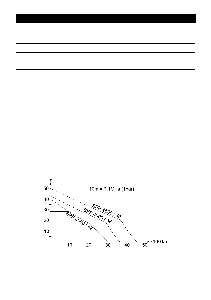
Technische Daten
BPP
3000/42
BPP
4000/48
BPP
4500/50
Spannung V 230 - 240 230 - 240 230 - 240
Frequenz Hz 50 50 50
Leistung P
nenn
W 700 900 1200
Max. Fördermenge l/h 3000 3700 4500
Max. Ansaughöhe m 8 8 8
Max. Druck der Pumpe MPa
(bar)
Arbeitsdruck MPa
(bar)
Max. Druck der Luftfüllung im Speicherkessel
Max. zulässiger Innendruck im Speicherkessel
MPa
(bar)
MPa
(bar)
0,40
(4,0)
0,17 - 0,28
(1,7 - 2,8)
0,18 - 0,2
(1,8 - 2,0)
0,50
(5,0)
0,43
(4,3)
0,17 - 0,30
(1,7 - 3,0)
0,18 - 0,2
(1,8 - 2,0)
0,50
(5,0)
0,50
(5,0)
0,17 - 0,32
(1,7 - 3,2)
0,18 - 0,2
(1,8 - 2,0)
0,50
(5,0)
Gewicht kg 16 16 17
Technische Änderungen vorbehalten!
Betriebsdruck und Fördermenge ist abhängig von der Ansaughöhe und der angeschlossenen Peripherie!
Die mögliche Fördermenge ist umso größer:
- je geringer die Ansaug- und Förderhöhen sind
- je größer die Durchmesser der verwendeten Schläuche sind
- umso kürzer die verwendeten Schläuche sind
- je weniger Druckverlust das angeschlossene Zubehör verursacht
12 DE
– 8
Page 13

Contents
Contents. . . . . . . . . . . . . . . EN . . .1
General information . . . . . . EN . . .1
Safety instructions . . . . . . . EN . . .2
Operation . . . . . . . . . . . . . . EN . . .3
Maintenance and Care. . . . EN . . .4
Transport . . . . . . . . . . . . . . EN . . .4
Storage. . . . . . . . . . . . . . . . EN . . .4
Special accessories . . . . . . EN . . .5
Troubleshooting . . . . . . . . . EN . . .6
Technical specifications . . . EN . . .8
General information
Dear Customer,
Please read and comply with
these original instructions prior
to the initial operation of your appliance and
store them for later use or subsequent owners.
Proper use
This appliance has been designed for use
in private households and is not intended
for commercial use.
The manufacturer is not responsible for any
damages that may occur on account of improper use or wrong operations.
The device is meant for use as house water
tank.
While using the pump for pressure build-up,
the maximum supply pressure of 1.0 bar
(pump entry) should not be exceeded.
Approved fluids that can be drained:
Used water
Well water
Water source
Rain water
Water from swimming pool (provided
the dosing of additives is proper)
몇 Warning
Caustic, slightly inflammable and other
explosive substances such as petrol,
petroleum, diluted nitrogen, greases,
oils, salt water and waste water from
toilets as well as sludgy water that has
a slower flow capacity than water,
should not be transported using the
pump. The temperature of the transported fluids should not exceed 35°C.
Environmental protection
The packaging material can be recy-
cled. Please do not place the packaging into the ordinary refuse for disposal,
but arrange for the proper recycling.
Old appliances contain valuable materials that can be recycled. Please
arrange for the proper recycling of
old appliances. Please dispose your old appliances using appropriate collection systems.
Notes about the ingredients (REACH)
You will find current information about the
ingredients at:
www.kaercher.com/REACH
Warranty
The warranty terms published by the relevant sales company are applicable in each
country. We will repair potential failures of
your appliance within the warranty period
free of charge, provided that such failure is
caused by faulty material or defects in manufacturing. In the event of a warranty claim
please contact your dealer or the nearest
authorized Customer Service centre.
Please submit the proof of purchase.
Symbols in the operating instruc-
tions
Danger
Immediate danger that can cause severe
injury or even death.
몇 Warning
Possible hazardous situation that could
lead to severe injury or even death.
Caution
Possible hazardous situation that could
lead to mild injury to persons or damage to
property.
– 1
13EN
Page 14

Safety instructions
Danger of death
Violating these safety instructions may result in death through electrocution.
Check the power cord with mains plug
for damage before every use. If the
power cord is damaged, please arrange
immediately for the exchange by an authorized customer service or a skilled
electrician.
All electrical sockets should be fixed in
an area that is protected against floods.
To separate the machine from the
mains, pull the plug and not the power
cord.
Do not scrape the power cord across
sharp edges and ensure that it does not
get pressed.
Install the appliance in a safe position at
a place protected against flooding.
The voltage indicated on the type plate
must correspond to the voltage of the
electrical source.
To avoid risks, all repairs and replace-
ment of spare parts may only be carried
out by the authorised customer service
personnel.
The pump does not switch off if there is
no water supply. The water in the pump
gets heated and can cause injury when
it comes out!
The pump may be operated for maximum 3 minutes in this operating status.
Tip: Dry run protection ((6.997-355.0),
swimmer switch (6.997-356.0) are
available as options!
Do not use this pump as an immersion
pump.
When using the pump near to pools,
garden ponds or fountains, observe a
minimum distance of 2m and safeguard
the device against slipping into the water.
Follow the rules for electrical safety of
equipment:
Only operate pumps near to pools, garden ponds or fountains, if they are
equipped with an earth leakage circuit
breaker with a nominal error current of
max. 30 mA. It is not permitted to activate the pump, if persons are in the pool
or garden pond.
For safety reasons, we recommend that
you operate the appliance only via a
earth-leakage circuit breaker (max. 30
mA).
The electrical connection of the system
may only be performed by a qualified
electrician. Please follow the respective
national regulations!
In Austria pumps to be used in swimming pools and garden ponds should
be equipped with a fixed connection line
according to ÖVE B/EN 60555 Part 1 to
3; power supply should be via a ÖVEtested isolating transformer whereby
the secondary nominal voltage should
not exceed 230V.
The appliance may be used by children
over the age of eight and individuals
with limited physical, sensory or cognitive abilities or lack of experience and
knowledge if they are under supervision
or were instructed regarding the safe
use of the appliance and understand
the resulting risks.
Supervise children to prevent them
from playing with the appliance.
Prerequisites for the appliance's
stability
Caution
Create stability for the appliance prior to all
work on or with the appliance to prevent accidents or damage.
– The stability of the appliance is warrant-
ed when it is placed onto an even surface.
14 EN
– 2
Page 15

Operation
Please follow the safety instructions before
start-up!
Description of the Appliance
1 Power cord with plug
2 Connection G1(33.3mm) Suction pipe
3 Connection G1(33.3mm) Pressure pipe
4 Filling nozzle with pre-filter
5 Pressure display
6 Drain opening
7 Backflow valve
Preparing the Appliance
Illustration
Before start-up, check the pressure of
the air filling in the storage boiler. If necessary, refill up to 2.0 bar in switched off
/ zero-pressure state.
Illustration
Secure device against slipping off (fix it
with screws, if needed).
Illustration
Install the non-return valve.
Connect the vacuum-proof suction
hose with integrated backflow stop on
the suction side.
(available as optional accessory)
Connect the pressure side for noise re-
duction to the pressure pipe via flexible
hose.
Illustration
To simplify the subsequent discharge
and pressure release of the system, we
recommend that a release cock be installed between pump and suction hose
/ non-return valve.
(not included in delivery)
Illustration
Unscrew the lid of the filling nozzle and
fill in water till it overflows.
Screw on the lid on the filling nozzle.
Open existing shutoff valves in the
pressure pipe.
Note: Even the smallest of leakages leads
to malfunctioning.
Operation
Insert the mains plug into the socket.
몇 Caution
Pump starts running immediately. Wait till
the pump sucks in and pumps uniformly,
then shut the gate valve in the pressure
pipe. The pressure switch deactivates the
motor when the shut-off pressure is
reached. The storage boiler is now full; the
domestic water supply system is ready for
operation.
If there is a lack of supplied water, the
switch-off pressure is not reached; the
pressure switch cannot shut off the appliance, the water in the pump head will then
heat up enough to damage the appliance.
In models BPP 4000/48 and BPP 4500/50,
the supplied power is interrupted by a thermal switch if there is an overheated condition. The supplied power is switched back
on after the appliance has cooled off.
We recommend installing a dry run protection unit to regulate the lack of water situation.
몇 Caution
System is under pressure!
(For pressure details see chapter on technical specifications)
Finish operation
Disconnect the main plug from the
socket.
– 3
15EN
Page 16

Maintenance and Care
Transport
Danger
Pull out the mains plug before doing any
maintenance or cleaning jobs.
System is under pressure!
After opening the filling or drain lid or before
separating the pipes, open the locking
valve on the pressure side and empty the
system via the drain tap (available in
plumbing stores).
Care
Illustration
Check pre-filter regularly for dirt. If it is
visibly dirty, proceed as follows:
Unscrew the lid of the filling nozzle.
Remove the pre-filter and clean it under
flowing water.
Maintenance
Illustration
Check the pressure of the air filling in
the storage boiler annually. If necessary, refill up to 2.0 bar in switched off /
zero-pressure state (disconnect device,
open the water cock).
Caution
In order to prevent accidents or injuries,
keep in mind the weight of the appliance
during transport (see Specifications).
When transporting by hand
Lift appliance by the carrying handle
and carry it.
When transporting in vehicles
Secure the appliance against shifting
and tipping over.
Storage
Caution
In order to prevent accidents or injuries,
keep in mind the weight of the appliance
when selecting a storage location for it (see
Specifications).
Storing the Appliance
Store the appliance in a frost free area.
16 EN
– 4
Page 17

Special accessories
The figures of the following special accessories can be found on page 4 of these instructions.
6.997-350.0 Suction assembly,
3.5 m
6.997-349.0 Suction assembly,
7.0m
6.997-348.0 Suction hose 3.5m Complete ready to connect, vacuum tight suction
6.997-347.0 Suction hose, by the
meter, 3/4" (19 mm)
25 m
6.997-346.0 Suction hose, by the
meter, 1" (25.4mm)
25 m
6.997-360.0 Suction hose for
driven well and pipelines
6.997-345.0 Suction filter Basic
3/4“(19 mm)
6.997-342.0 Suction filter Basic
1“(25.4 mm)
Complete, ready to connect, vacuum-tight suction
hose with suction filter and backflow preventer. Can
also be used as an extension for the suction hose.
3/4“ (19 mm) hose with G1 (33.3 mm) threaded
connection.
hose for direct connection to the pump. To extend
the suction assembly or for use with suction filters.
3/4“ (19 mm) hose with G1 (33.3 mm) threaded
connection.
Vacuum-tight spiral hose, to be cut into individual
lengths. Can be used as individual suction assembly combined with connections and suction filters.
Vacuum-tight spiral hose to be connected on the
suction side of the pump. 1“ (25.4 mm) hose with
threaded connection G1 (33.3 mm) on both ends.
Caution: The suction hose may not be used as a
pressure hose.
To be connected to the suction hose meter length.
The backflow preventer shortens the re-suction
time. (including hose clamps)
6.997-341.0 Suction filter Premi-umTo be connected to the suction hose meter length.
The backflow preventer shortens the re-suction
time. (including hose clamps). Durable metal/plastic construction. Suitable for 3/4“ (19 mm) or 1“
(25.4 mm) hoses.
6.997-343.0 Prefilter (flow up to
3,000 l/h)
6.997-344.0 Prefilter (flow up to
6,000 l/h)
Pump prefilter to protect the pump from coarse dirt
particles or sand. The filter insert can removed for
cleaning. With G1 (33.3 mm) threaded connection.
– 5
17EN
Page 18
6.997-359.0 Pump connection
piece G1 (33.3 mm)
Suitable for 3/4“ (19 mm) or 1“ (25.4 mm) hoses.
With G1“ (33.3 mm) threaded connection. Including
backflow valve, flat seal and hose clamp. If used for
garden pumps, install the flat seal.
6.997-358.0 Connection kit Basic
G1 (33.3 mm)
6.997-340.0 Connection kit Premium G1(33.3 mm)
6.997-356.0 Swimmer switch Switches the pump on and off automatically de-
6.997-355.0 Dry run fuse If no more water flows through the pump, the dry
6.997-417.0 Pressure compensating hose 3/4“
(19mm), 1m
To connect 1/2“ (12.7 mm) water hoses to pumps
with G1 (33.3 mm) threaded connections.
To connect 3/4“ (25.4mm) water hoses to pumps
with G1 (33.3 mm) threaded connections. For increased water flow.
pending on the water level in the water tank. With
10 m special connection cable.
run fuse will protect the pump from damage and automatically turn it off. With G1“ (33.3 mm) threaded
connection.
Connecting hose for the pressure compensation in
the domestic water supply system. To connect the
pump to rigid pipe line systems. Furthermore, the
internal storage volume in the hose prevents frequent switching on and off of the pump.
Troubleshooting
Danger
To avoid risks, all repairs and replacement of spare parts may only be carried out by authorized customer service personnel.
First pull out the plug from the mains before carrying out any tasks on the machine.
Fault Cause Remedy
Pump runs but
does not transport
Pump does not
run or suddenly
comes to a
standstill during
operations
18 EN
Air in the pump Refer to Chapter "Preparation" Figure
Air does not come out on the
pressure side
Power supply interrupted Check fuses and electrical connec-
Thermal protection switch in
the motor has switched off the
pump as it was overheated.
– 6
E
Open tap on pressure side
tions
Pull out the mains plug, let the pump
cool down, clean the suction area,
prevent dry running
Page 19

Fault Cause Remedy
Pump switches
itself off and
back on (BPP
4000/48 and
BPP 4500/50)
Motor starts up
immediately after switch off
Pump transports is reducing or
transported
quantity is too
low
Thermal protection fuse has
switched the pump off to protect from overheating or turned
it back on after it has cooled
off.
Pressure is not retained in the
system
Air pressure in the storage
boiler is too low.
Backflow valve does not close
properly
Membrane in pressure tank is
defective
Suction filter or backflow valve
contaminated
The quantity transported by
the pump depends on the
transport height and the connected periphery
Pre-filter is dirty Remove the pre-filter and clean it un-
In order to prevent a repetition, the
system should be checked for leaks
and sealed.
Check connections including sealings
and control the water outlet.
The smallest of leakages can affect
the operation adversely.
Fill storage boiler with 2.0 bar. Refer
to Chapter "Maintenance" Figure A
Check backflow valve on suction side.
Replace membrane
Clean suction filter or backflow valve
Keep max. flow height, see technical
data. If necessary, select a different
hose diameter or hose length.
der flowing water.
Vibrating sound
while taking out
water
Our Kärcher branch will be pleased to help you further in the case of questions or faults.
See address on the reverse.
Membrane in pressure tank vibrates
– 7
Noise caused by operations and the
noise can be reduced by reducing the
pressure in the air filling of the storage
tank.
19EN
Page 20

Technical specifications
BPP
3000/42
BPP
4000/48
BPP
4500/50
Voltage V 230 - 240 230 - 240 230 - 240
Frequency Hz 50 50 50
Output P
nom
W 700 900 1200
Max. flow rate l/h 3000 3700 4500
Max. Suction height m 8 8 8
Max. pump pressure MPa
(bar)
Working pressure MPa
(bar)
Max. air pressure in the storage tank MPa
(bar)
Max. permissible internal pressure in
the storage tank
MPa
(bar)
0,40
(4,0)
0,17 - 0,28
(1,7 - 2,8)
0,18 - 0,2
(1,8 - 2,0)
0,50
(5,0)
0,43
(4,3)
0,17 - 0,30
(1,7 - 3,0)
0,18 - 0,2
(1,8 - 2,0)
0,50
(5,0)
0,50
(5,0)
0,17 - 0,32
(1,7 - 3,2)
0,18 - 0,2
(1,8 - 2,0)
0,50
(5,0)
Weight kg 16 16 17
Subject to technical modifications!
Operating pressure and transported quantity depends on the suction height and
the connected periphery!
The possible feed volume is even larger:
- the lower the suction and flow heights
- the larger the diameter of the hoses used
- the shorter the hoses used are
- the lower the pressure loss caused by the connected accessories
20 EN
– 8
Page 21
Table des matières
Table des matières. . . . . . . FR . . .1
Consignes générales . . . . . FR . . .1
Consignes de sécurité . . . . FR . . .2
Utilisation . . . . . . . . . . . . . . FR . . .3
Entretien, maintenance . . . FR . . .4
Transport . . . . . . . . . . . . . . FR . . .4
Entreposage. . . . . . . . . . . . FR . . .4
Accessoires en option . . . . FR . . .5
Assistance en cas de panne FR . . .6
Caractéristiques techniques FR . . .8
Consignes générales
Cher client,
Lire cette notice originale avant
la première utilisation de votre
appareil, se comporter selon ce qu'elle requièrt et la conserver pour une utilisation ultérieure ou pour le propriétaire futur.
Utilisation conforme
Cet appareil ne doit être utilisé que pour un
usage domestique.
Le fabricant décline tout responsabilité en
cas de dommages issus d'une utilisation
non conforme ou incorrecte de l'appareil.
L'appareil est destiné à une utilisation
comme générateur domestique.
La pression maximale de la conduite
d'amenée de 1,0 bar (entrée de la pompe)
ne doit pas être dépassée lorsque la
pompe est utilisée pour le renforcement de
la pression.
Fluides d'alimentation autorisés :
Eau d'usage
Eau de puits
Eau de source
Eau de pluie
Eau de piscine (dosage de l'additif se-
lon les dispositions imposé au préalable)
몇 Avertissement
Il est interdit de transporter des substances corrosives, facilement inflammables ou explosives (par ex. essence,
pétrole, diluant pour laque cellulosique), graisses, huiles, eau salée et
eaux usées en provenance des toilettes
et pour les eaux boueuses dont la fluidité est inférieure à celle de l'eau. La température du fluide transporté ne doit pas
dépasser 35° C.
Protection de l’environnement
Les matériaux constitutifs de l’em-
ballage sont recyclables. Ne pas jeter les emballages dans les ordures
ménagères, mais les remettre à un système de recyclage.
Les appareils usés contiennent des
matériaux précieux recyclables les-
quels doivent être apportés à un
système de recyclage. Pour cette raison,
utilisez des systèmes de collecte adéquats
afin d'éliminer les appareils usés.
Instructions relatives aux ingrédients
(REACH)
Les informations actuelles relatives aux ingrédients se trouvent sous :
www.kaercher.com/REACH
Garantie
Dans chaque pays, les conditions de garantie en vigueur sont celles publiées par
notre société de distribution responsable.
Les éventuelles pannes sur l’appareil sont
réparées gratuitement dans le délai de validité de la garantie, dans la mesure où
celles-ci relèvent d'un défaut matériel ou
d'un vice de fabrication. En cas de recours
en garantie, adressez-vous à votre revendeur ou au service après-vente agréé le
plus proche munis de votre preuve d'achat.
– 1
21FR
Page 22

Symboles utilisés dans le mode
d'emploi
Danger
Pour un danger immédiat qui peut avoir
pour conséquence la mort ou des blessures corporelles graves.
몇 Avertissement
Pour une situation potentiellement dangereuse qui peut avoir pour conséquence des
blessures corporelles graves ou la mort.
Attention
Pour une situation potentiellement dangereuse qui peut avoir pour conséquence des
blessures légères ou des dommages matériels.
Consignes de sécurité
Danger de mort
Danger de mort par le courant électrique en
cas de non-respect des consignes de sécurité !
Vérifier avant chaque utilisation que le
câble et la fiche mâle ne sont pas défectueux. Un câble d’alimentation endommagé doit immédiatement être
remplacé par le service après-vente ou
un électricien agréé.
Toutes les connexions enfichées élec-
triques doivent être effectuées dans
une zone protégée contre les inondations.
Pour débrancher l'appareil, tirer au ni-
veau de la fiche secteur et non sur le
câble d'alimentation.
Ne pas faire passer le câble d'alimenta-
tion sur des arêtes vives et ne pas le
coincer.
Disposer l'appareil à un endroit stable
et qui ne risque pas d'être inondé.
La tension indiquée sur la plaque signa-
létique de l'appareil doit correspondre à
celle de la prise.
Afin d'éviter tout danger, seul le service
après-vente agréé est habilité à effectuer des réparations ou à monter des
pièces de rechanger sur l'appareil.
En cas d'absence d'alimentation en
eau, la pompe se met hors service.
L'eau chauffe dans la pompe et peut
provoquer des blessures lorsqu'elle en
sort.
Exploiter la pompe pendant max. 3 minutes dans ce mode de fonctionnement.
Conseil : la sécurité contre la marche à
sec (6.997-355.0) et l'interrupteur à flotteur (6.997-356.0) sont disponibles en
option !
La pompe ne doit pas être utilisée
comme pompe submersible.
En cas d'utilisation de la pompe près de
piscines, d'étangs de jardin ou de fontaines, respecter une distance minimale
de 2 m et bloquer l'appareil contre tout
glissement dans l'eau.
Respecter les dispositifs de sécurité
électriques :
Les pompes peuvent être exploitées
près des piscines, des étangs de jardin
et des fontaines uniquement avec un
disjoncteur à courant de défaut d'une
intensité nominale de max. 30 mA. Si
des personnes se trouvent dans les piscines ou l'étang de jardin, la pompe ne
doit pas être utilisée.
Pour des raisons de sécurité, nous recommandons fondamentalement que
l'appareil soit exploité avec un disjoncteur de courant de défaut (max. 30mA).
Le raccordement électrique doit être
exécuté uniquement par un électricien.
Respecter impérativement les dispositions nationales pour cette opération !
En Autriche les pompes qui sont destinées à une utilisation près des piscines
et des étangs de jardin qui sont équipés
d'une conduite de raccordement fixe
doivent être, selon ÖVE B/EN 60555
parties 1 à 3, alimentées par un transformateur d'isolation contrôlé selon
ÖVE, la tension nominale secondaire
ne devant pas dépasser 230V.
L'appareil peut être utilisé par des en-
fants à partir de huit ans personnes
22 FR
– 2
Page 23

ayant des capacités physiques, sensorielles ou intellectuelles réduites ou par
des personnes qui manquent d'expérience ou de connaissances si elles
sont surveillées ou informées de
l'usage sûr de l'appareil et des dangers
qui peuvent en résulter.
Surveiller les enfants pour s'assurer
qu'ils ne jouent pas avec l'appareil.
Conditions pour la stabilité
Attention
Avant d'effectuer toute opération avec ou
sur le travail, en assurer la stabilité afin
d'éviter tout accident ou tout endommagement.
– La stabilité de l'appareil est assurée
lorsqu'il peut être posé sur une surface
plane.
Utilisation
Avant la mise en service de la pompe, respecter impérativement les consignes de
sécurité !
Description de l’appareil
1 Câble d’alimentation avec fiche secteur
2 Raccord G1(33,3 mm) conduite d'aspi-
ration
3 Raccord G1(33,3 mm) conduite de
pression
4 Tubulure de remplissage avec préfiltre
5 Affichage de la pression
6 Orifice de rejet
7 Clapet antiretour
Préparation
Illustration
Avant la mise en service, contrôler la
pression du remplissage d'air dans la
chaudière réservoir, le cas échéant
faire l'appoint à 2,0 bar en état hors
pression / hors service.
Illustration
Protéger l'appareil contre tout glisse-
ment (le visser éventuellement).
Illustration
Monter la soupape anti-retour.
Raccorder un flexible d'aspiration résis-
tant à la dépression avec clapet anti-retour intégré du côté aspiration
(accessoire disponible en option)
Connecter le côté pression avec un
tuyau flexible à la conduite de pression
pour la réduction du bruit.
Illustration
pour simplifier la purge et l'élimination
de la pression du système à l'avenir,
nous recommandons de monter un robinet de purge entre la pompe et le
flexible d'aspiration / le clapet anti-retour.
(ces éléments ne font pas partie de
l’étendue de livraison).
Illustration
Déviser le couvercle de la tubulure de
remplissage et remplir d'eau jusqu'au
débordement.
Visser fermement le couvercle sur la tu-
bulure de remplissage.
Ouvrir les vannes d'arrêt présentes
dans la conduite de pression.
Remarque : Les fuites les plus minimes
entraînent un dysfonctionnement.
Fonctionnement
Brancher la fiche secteur dans une
prise de courant.
몇 Attention
La pompe démarre immédiatement. Attendre jusqu'à ce que la pompe aspire et
transporte uniformément, puis fermer les
soupapes d'arrêt dans la conduite de pression. Après voir atteint la pression de mise
hors service, le pressostat coupe le moteur.
La chaudière réservoir est maintenant remplie, le système d'eau domestique est opérationnel.
Si l'alimentation en eau est défectueuse, la
pression d'arrêt n'est pas atteinte, le pressostat ne peut plus arrêter l'appareil, l'eau
dans la tête de pompe est chauffée jusqu'à
endommager l'appareil. Dans les appareils
BPP 4000/48 et BPP 4500/50, l'alimentation électrique en cas de surchauffe est in-
– 3
23FR
Page 24

terrompue par un thermocontact. Après le
refroidissement, l'alimentation électrique
est de nouveau générée.
Nous recommandons l'utilisation d'une protection contre la marche à sec pour que
votre appareil soit en permanence protégé
en cas de manque d'eau.
몇 Attention
Le système est sous pression !
(Pression, voir chapitre "Caractéristiques
techniques")
Fin de l'utilisation
Débrancher la fiche secteur.
Entretien, maintenance
Danger
Toujours débrancher la fiche de secteur
avant d'effectuer des travaux de maintenance et de réparation.
Le système est sous pression !
Avant d'ouvrir le couvercle de remplissage
et de purge ou avant de couper les
connexions des conduites, ouvrir la soupape d'arrêt côté pression et purger le système avec le robinet de purge (disponible
chez votre revendeur spécialisé).
Entretien
Illustration
Contrôler régulièrement l'encrassement
du préfiltre. Procéder de la manière sui-
vante pour les salissures visibles :
Dévisser le couvercle du col de remplis-
sage.
Retirer le préfiltre et le nettoyer à l'eau
courante.
Maintenance
Illustration
Contrôler chaque année la pression du
remplissage d'air dans la chaudière ré-
servoir, le cas échéant faire l'appoint à
2,0 bar (débrancher l'appareil, ouvrir le
robinet d'eau) en état hors pression /
hors service.
Transport
Attention
Afin d'éviter tout accident ou toute blessure
lors du transport, tenir compte du poids de
l'appareil (voir les caractéristiques techniques).
Transport manuel
Soulever l'appareil avec la poignée et le
porter.
Transport dans des véhicules
Freiner l'appareil pour l'empêcher de
glisser et de basculer.
Entreposage
Attention
Afin d'éviter tout accident ou toute blessure, tenir compte du poids de l'appareil
(voir les caractéristiques techniques) en
choisissant son emplacement pour le stockage.
Ranger l’appareil
Conserver l'appareil dans un lieu à l'abri
du gel.
24 FR
– 4
Page 25

Accessoires en option
Les illustrations des accessoires en option présentés ci-dessous se trouvent sur la page
4 de ce manuel.
6.997-350.0 Garniture d'aspiration 3,5m
6.997-349.0 Garniture d'aspiration 7,0m
6.997-348.0 Tuyau d'aspiration
3,5m
6.997-347.0 Tuyau d'aspiration
au mètre 3/4“
(19mm) 25m
6.997-346.0 Tuyau d'aspiration
au mètre 1“
(25,4mm) 25m
6.997-360.0 Flexible d'aspiration
pour puits abyssins
et conduites tubulaires
6.997-345.0 Filtre d'aspiration
Basic 3/4“(19mm)
6.997-342.0 Filtre d'aspiration
Basic 1“(25,4mm)
Tuyau d'aspiration résistant au vide, entièrement
prêt à être connecté avec filtre d'aspiration et clapet
anti-retour. Aussi utilisable comme rallonge du
tuyau d'aspiration. Tuyau 3/4“ (19mm) avec filetage
de raccord G1 (33,3mm).
Tuyau d'aspiration résistant au vide, entièrement
prêt à être connecté pour une connexion directe à
la pompe. Pour le prolongement de la garniture
d'aspiration ou pour une utilisation avec des filtres
d'aspiration. Tuyau 3/4“ (19mm) avec filetage de
raccord G1 (33,3mm).
Tuyau spiralé résistant au vide pour la découpe de
longueurs de tuyau individuelles. Combiné à des
pièces de raccordement et des filtres d'aspiration,
aussi utilisable comme garniture d'aspiration individuelle.
Flexible en spirale résistant au vide pour le raccordement au côté dépression de la pompe. Flexible 1“
(25,4mm) avec filetage de raccordement
G1(33,3mm) des deux côtés. Attention : Le flexible
d'aspiration ne doit pas être mis en œuvre comme
flexible de pression.
Pour la connexion au tuyau d'aspiration au mètre.
Le clapet anti-retour raccourcit le temps de réaspiration. (avec pinces à tuyau)
6.997-341.0 Filtre d'aspiration
Premium
6.997-343.0 Préfiltre (débit jusqu'à 3000 l/h)
6.997-344.0 Préfiltre (débit jusqu'à 6 000 l/h)
Pour la connexion au tuyau d'aspiration au mètre.
Le clapet anti-retour raccourcit le temps de réaspiration. (avec pinces à tuyau). Version robuste en
métal et plastique. Convient pour les tuyaux de 3/4“
(19mm) ou 1“ (25,4mm).
Préfiltre de la pompe pour protéger la pompe des
grandes particules de saletés ou du sable. La cartouche de filtre peut être prélevée pour le nettoyage. Avec un filetage de raccord G1 (33,3mm).
– 5
25FR
Page 26

6.997-359.0 Elément de raccordement de pompe
G1 (33,3mm)
Convient pour les tuyaux de 3/4“ (19 mm) ou 1“
(25,4 mm). Avec un filetage de raccord G1
(33,3mm). Y compris soupape anti-retour, joint plat
et collier. Utiliser le joint plat en cas d'utilisation pour
pompes de jardin.
6.997-358.0 Bloc de raccordement Basic G1
(33,3mm)
6.997-340.0 Bloc de raccordement Premium G1
(33,3mm)
6.997-356.0 Interrupteur à flotteur
6.997-355.0 Sécurité contre la
marche à sec
6.997-417.0 Flexible de compensation de pression 3/
4“ (19mm), 1m
Pour la connexion de tuyaux d'eau de 1/2“
(12,7mm) aux pompes avec filetage de raccord G1
(33,3mm).
Pour la connexion de tuyaux d'eau de 3/4“
(25,4mm) aux pompes avec filetage de raccord G1
(33,3mm). Pour un débit d'eau plus important.
Allume et éteint automatiquement la pompe en
fonction du niveau du réservoir d'eau. Avec câble
de raccordement spécial de 10 m.
Si aucune eau ne coule à travers la pompe, la sécurité contre la marche à sec protège la pompe des
dégâts et l'éteint automatiquement. Avec un filetage de raccord G1“ (33,3mm).
Flexible de raccordement pour la compensation de
pression dans l'installation d'eau domestique. Pour
le raccordement de la pompe à des systèmes de
conduite rigides. Un volume de réserve interne
dans le flexible empêche en outre une mise en et
hors service fréquente de la pompe.
Assistance en cas de panne
Danger
Afin d'éviter tout danger, seul le service après-vente agréé est habilité à effectuer des réparations ou à monter des pièces de rechanger sur l'appareil.
Avant d'effectuer tout type de travaux sur l'appareil, le mettre hors service et débrancher
la fiche électrique.
Panne Cause Remède
La pompe
tourne mais ne
débite pas
26 FR
Air dans la pompe voir chapitre "Préparer" ill. E
La pression ne peut pas
s'échapper côté pression
– 6
Ouvrir le point de prélèvement côté
pression
Page 27

Panne Cause Remède
La pompe ne
tourne pas ou
s'arrête soudainement en
cours de fonctionnement
La pompe se
coupe d'ellemême et remet
en marche
(BPP 4000/48
et BPP 4500/
50)
Le moteur redémarre immédiatement après la
mise hors service
Alimentation électrique coupée
Le disjoncteur thermique dans
le moteur a mis la pompe hors
service en raison d'une surchauffe du moteur.
L'interrupteur thermique a coupé la pompe pour la protéger
contre les surcharges ou l'a remise en marche après son refroidissement.
La pression est perdue dans le
système
La pression d'air est trop
basse dans la chaudière réservoir.
Le clapet anti-retour ne ferme
pas correctement
Membrane défectueuse dans
le réservoir de pression
Contrôler les fusibles et les
connexions électriques
Débrancher la fiche secteur, laisser
refroidir la pompe, nettoyer la zone
d'aspiration, empêcher qu'elle ne
tourne à sec
Afin de prévenir toute répétition, le
système devrait être vérifié quant à la
présence de fuites, puis étanché.
Contrôler les connexions, y compris
joints et vérifier la sortie d'eau.
Les fuites les plus minimes affectent
le fonctionnement.
Remplir la chaudière réservoir à 2,0
bar. voir chapitre "Entretien" ill. A
Contrôler le clapet anti-retour côté
pression.
Remplacer la membrane
Le débit diminue ou est trop
faible
Bruit de vibration lors du prélèvement de
l'eau
Notre succursale Kärcher se tient à votre entière disposition pour d'éventuelles questions
ou problèmes. L'adresse figure au dos.
Filtre d'aspiration ou clapet
anti-retour impur
Le débit de la pompe dépend
de la hauteur manométrique et
des périphériques raccordés
Préfiltre sale Retirer le préfiltre et le nettoyer à l'eau
La membrane dans le réservoir de pression vibre
Nettoyer le filtre d'aspiration ou le clapet anti-retour
Respecter la hauteur manométrique
max., cf. les caractéristiques techniques, le cas échéant sélectionner
un autre diamètre de flexible ou une
autre longueur de flexible.
courante.
Bruit provoqué par le fonctionnement
qui peut être éliminé en réduisant la
pression de remplissage d'air dans la
chaudière réservoir.
– 7
27FR
Page 28

Caractéristiques techniques
BPP
3000/42
BPP
4000/48
BPP
4500/50
Tension V 230 - 240 230 - 240 230 - 240
Fréquence Hz 50 50 50
Puissance P
nom
W 700 900 1200
Débit max. l/h 3000 3700 4500
Hauteur max. de l'aspiration m 8 8 8
Pression maximale de la pompe MPa
(bar)
Pression de service MPa
(bar)
Pression max. du remplissage d'air
dans la chaudière réservoir
Pression interne maximale admissible
dans la chaudière réservoir
MPa
(bar)
MPa
(bar)
0,40
(4,0)
0,17 - 0,28
(1,7 - 2,8)
0,18 - 0,2
(1,8 - 2,0)
0,50
(5,0)
0,43
(4,3)
0,17 - 0,30
(1,7 - 3,0)
0,18 - 0,2
(1,8 - 2,0)
0,50
(5,0)
0,50
(5,0)
0,17 - 0,32
(1,7 - 3,2)
0,18 - 0,2
(1,8 - 2,0)
0,50
(5,0)
Poids kg 16 16 17
Sous réserve de modifications techniques !
La pression de service et le débit de la pompe dépendent de la hauteur de l'apiration et des périphériques raccordés !
La quantité transportée possible augmente
- parallèlement à la réduction des hauteurs de transport et d'aspiration
- Plus le diamètre des flexibles utilisés est grand,
- plus les flexibles utilisés sont petits
- moins les accessoires raccordés ne causent de perte de pression
28 FR
– 8
Page 29

Indice
Indice . . . . . . . . . . . . . . . . . IT . . .1
Avvertenze generali . . . . . . IT . . .1
Norme di sicurezza . . . . . . IT . . .2
Uso. . . . . . . . . . . . . . . . . . . IT . . .3
Cura e manutenzione. . . . . IT . . .4
Trasporto . . . . . . . . . . . . . . IT . . .4
Supporto. . . . . . . . . . . . . . . IT . . .4
Accessori optional . . . . . . . IT . . .5
Guida alla risoluzione dei guasti IT . . .6
Dati tecnici . . . . . . . . . . . . . IT . . .8
Avvertenze generali
Gentile cliente,
Prima di utilizzare l'apparecchio
per la prima volta, leggere le
presenti istruzioni originali, seguirle e conservarle per un uso futuro o in caso di rivendita dell'apparecchio.
Uso conforme a destinazione
Questo apparecchio è concepito per il solo
uso domestico e non deve essere adibito
ad uso commerciale o industriale.
Il produttore non è responsabile per eventuali danni causati dall'uso improprio e/o
uso che non corrisponde a quello conforme
a destinazione.
L'apparecchio è indicato per essere impiegato come impianto di acqua di servizio.
Nel caso in cui la pompa venga impiegata
per l'incremento della pressione, la pressione di mandata max. non deve superare 1,0
bar (entrata pompa).
Liquidi trasportabili consentiti:
Acqua riciclata
acqua di pozzo
acqua sorgiva
acqua piovana
Acqua piscine (partendo da un dosag-
gio conforme degli additivi)
몇 Attenzione
Non è possibile trasportare materiali irritanti, facilmente infiammabili o esplosivi (ad es. benzina, petrolio,
nitrodiluente), grassi, oli, acqua salata e
acque di scarico delle toilette ed acquafango con una fluidità inferiore all'acqua. La temperatura del liquido trasportato non deve superare i 35° C.
Protezione dell’ambiente
Tutti gli imballaggi sono riciclabili. Gli
imballaggi non vanno gettati nei rifiuti
domestici, ma consegnati ai relativi centri di
raccolta.
Gli apparecchi dismessi contengono materiali riciclabili preziosi e van-
no perciò consegnati ai relativi centri
di raccolta. Si prega quindi di smaltire gli
apparecchi dismessi mediante i sistemi di
raccolta differenziata.
Avvertenze sui contenuti (REACH)
Informazioni aggiornate sui contenuti sono
disponibili all'indirizzo:
www.kaercher.com/REACH
Garanzia
Le condizioni di garanzia valgono nel rispettivo paese di pubblicazione da parte
della nostra società di vendita competente.
Entro il termine di garanzia eliminiamo gratuitamente eventuali guasti all’apparecchio,
se causati da difetto di materiale o di produzione. Nei casi previsti dalla garanzia si
prega di rivolgersi al proprio rivenditore, oppure al più vicino centro di assistenza autorizzato, esibendo lo scontrino di acquisto.
Simboli riportati nel manuale d'uso
Pericolo
Per un rischio imminente che determina lesioni gravi o la morte.
몇 Attenzione
Per una situazione di rischio possibile che
potrebbe determinare lesioni gravi o la morte.
Attenzione
Per una situazione di rischio possibile che
potrebbe determinare danni leggeri a persone o cose.
– 1
29IT
Page 30

Norme di sicurezza
Pericolo di morte
In caso di inosservanza delle avvertenze di
sicurezza sussiste il pericolo di morte a
causa di scosse elettriche!
Prima di ogni utilizzo controllate even-
tuali danni sulla linea di allacciamento e
sulla spina di alimentazione. Lasciate
sostituire immediatamente la linea di allacciamento danneggiata dal servizio
clienti autorizzato/personale specializzato in elettricità.
Tutte le connessioni elettriche a spina
devono essere collocate in una zona
antiallagamento.
Non scollegare la spina dalla presa ti-
rando il cavo di collegamento.
Tenere lontano il cavo di allacciamento
da spigoli vivi ed evitare di schiacciarlo.
Montare l'apparecchio in modo stabile e
antiallagamento.
La tensione indicata sulla targhetta
dell'apparecchio deve corrispondere a
quella della sorgente di corrente.
Per escludere qualsiasi rischio, gli inter-
venti di riparazione e il montaggio dei
pezzi di ricambio vanno effettuati esclusivamente dal servizio assistenza autorizzato.
In caso di assenza di alimentazione idri-
ca, la pompa non si disattiva. L'acqua
nella pompa si surriscalda ed alla fuoriuscita potrebbe comportare gravi lesioni!
Alimentare la pompa per max. 3 minuti
in questo stato operativo.
Consiglio: Dispositivo di sicurezza per il
funzionamento a secco (6.997-355.0),
interruttore a galleggiante (6.997-
356.0) disponibili opzionalmente!
La pompa non può essere usata come
pompa sommersa.
Nel caso in cui si utilizzi la pompa in pi-
scine, vasche da giardino o fontane, rispettare una distanza minima di 2m ed
assicurare l'apparecchio affinché non
possa scivolare in acqua.
Rispettare le norme vigenti per i dispo-
sitivi elettrici di protezione:
Le pompe possono essere utilizzate in
piscine, vasche da giardino e fontane a
getto solo con un interruttore differenziale con una corrente di guasto nominale di max. 30 mA. Non utilizzare la
pompa se nella piscina o nella vasca da
giardino si trovano delle persone.
Per motivi di sicurezza si consiglia in linea di principio di utilizzare l'apparecchio solo con un interruttore
differenziale (max. 30 mA).
Il collegamento elettrico deve essere
eseguito solo da un elettricista qualificato. Osservare assolutamente le disposizioni nazionali vigenti.
In Austria le pompe da utilizzare per piscine e vasche da giardino, dotate di
una linea di allacciamento fissa, devono
essere alimentate secondo ÖVE B/EN
60555 parte 1-3, mediante un trasformatore di separazione certificato ÖVE,
laddove la tensione nominale secondaria non deve superare i 230 V.
Questo apparecchio è indicato per es-
sere usato da bambini con età di 8 anni
e più e da persone con delle limitate capacità fisiche, sensoriali o mentali e da
persone che abbiano poca esperienza
e/o conoscenza dell'apparecchio, solo
se queste vengono supervisionate oppure se hanno ricevuto istruzioni su
come usare l'apparecchio e che abbiano capito i pericoli derivanti dall'uso.
Sorvegliare i bambini per assicurarsi
che non giochino con l'apparecchio.
Presupposti per la stabilità
Attenzione
Prima di qualsiasi intervento con o sull'apparecchio è necessario renderlo stabile per
evitare incidenti o danneggiamenti.
– La stabilità dell'apparecchio è garantita
quando viene posizionato su una superficie piana.
30 IT
– 2
Page 31

Uso
Prima di mettere in funzione la pompa è necessario osservare le avvertenze di sicurezza!
Descrizione dell’apparecchio
1 Cavo di allacciamento alla rete con spi-
na
2 Collegamento tubo di aspirazione
G1(33,3mm)
3 Collegamento tubo di mandata
G1(33,3mm)
4 Bocchettone di riempimento con pre-fil-
tro
5 Indicatore di pressione
6 Apertura di scarico
7 Valvola di non ritorno
Operazioni preliminari
Figura
Prima della messa in esercizio control-
lare la pressione dell'aria nell'accumu-
latore. Se necessario rabboccare allo
stato disattivato / depressurizzato a 2,0
bar.
Figura
Assicurare l'apparecchio affinché non
possa scivolare (event. avvitarlo).
Figura
Montare la valvola di non ritorno.
Collegare un tubo flessibile di aspirazio-
ne resistente al vuoto con un dispositivo
antiriflusso integrato al lato di aspirazio-
ne.
(disponibile come accessorio optional)
Per la riduzione della rumorosità, colle-
gare il lato di mandata al tubo di manda-
ta con un tubo flesssibile.
Figura
Per semplificare il successivo svuota-
mento e lo scarico della pressione dal
sistema, consigliamo il montaggio di un
rubinetto di scarico tra pompa e il tubo
di mandata / la valvola di non ritorno.
(non compreso nella fornitura)
Figura
Svitare il coperchio sul bocchettone di
riempimento e versare acqua fino alla
fuoriuscita.
Stringere a mano l'apparecchio sul boc-
chettone di riempimento.
Aprire le valvole di chiusura presenti nel
tubo di mandata.
Avviso: Perdite anche minime determinano un malfunzionamento.
Funzionamento
Inserire la spina in una presa elettrica.
몇 Attenzione
La pompa si avvia immediatamente. Attendere fino a quando la pompa aspira ed alimenta, quindi chiudere le valvole di
chiusura nel tubo di mandata. Dopo il raggiungimento della pressione di arresto, il tasto a pressione disattiva il motore.
L'accumulatore a questo punto è pieno,
l'impianto di acqua di servizio è pronto.
In assenza di acqua la pressione di disinserimento non viene raggiunta, il pressostato
non può più spegnere l'apparecchio, l'acqua nella testata della pompa si surriscalda
fino al danneggiamento dell'apparecchio.
Negli apparecchi BPP 4000/48 e BPP
4500/50 in caso di surriscaldamento la
mandata di corrente viene interrotta da un
termointerruttore. La mandata di corrente
viene ripristinata dopo il loro raffreddamento.
Come protezione dalla mancanza d'acqua
regolare, consigliamo di impiegare una sicurezza contro il funzionamento a secco.
몇 Attenzione
Il sistema è sotto pressione!
(per la pressione consultare il capitolo dei
dati tecnici)
Dopo l’uso
Staccare la spina di alimentazione dalla
presa.
– 3
31IT
Page 32

Cura e manutenzione
Trasporto
Pericolo
Prima di qualsiasi intervento di manutenzione o di pulizia, estrarre la spina di alimentazione.
Il sistema è sotto pressione!
Prima di aprire il coperchio di riempimento
o di chiusura oppure prima di scollegare i
raccordi, aprire la valvola di chiusura sul
lato di mandata e svuotare il sistema attraverso il rubinetto di scarico (disponibile nei
negozi specializzati).
Cura
Figura
Controllare regolarmente il pre-filtro e
verificare la presenza di impurità. In
caso di impurità visibili, procedere nel
modo seguente:
Svitare il coperchio sul bocchettone di
riempimento.
Rimuovere il pre-filtro e pulirlo sotto ac-
qua corrente.
Manutenzione
Figura
Controllare una volta all'anno la pres-
sione dell'aria nell'accumulatore. Se ne-
cessario rabboccare allo stato
disattivato / depressurizzato a 2,0 bar
(disattivare l'apparecchio, aprire il rubi-
netto).
Attenzione
Per prevenire incidenti o lesioni durante il
trasporto è necessario rispettare il peso
dell'apparecchio (vedi dati tecnici).
Posizione manuale
Sollevare l'apparecchio con l'apposito
manico e trasportarlo.
Posizione in veicoli
Bloccare l'apparecchio in modo tale che
non possa scivolare o ribaltarsi.
Supporto
Attenzione
Per prevenire incidenti o lesioni nella scelta
del luogo di stoccaggio è necessario rispettare il peso dell'apparecchio (vedi dati tecnici).
Deposito dell’apparecchio
Conservare l'apparecchio in un luogo
protetto dal gelo.
32 IT
– 4
Page 33

Accessori optional
Le illustrazioni relative agli accessori speciali riportate di seguito si trovano a pagina 4 delle presenti istruzioni.
6.997-350.0 Raccordo di aspirazione 3,5m
6.997-349.0 Raccordo di aspirazione 7,0m
6.997-348.0 Tubo di aspirazione
3,5m
6.997-347.0 Tubo flessibile di
aspirazione a metro
3/4“ (19mm) 25m
6.997-346.0 Tubo flessibile di
aspirazione a metro
1“ (25,4mm) 25m
6.997-360.0 Tubo flessibile di
aspirazione per pozzi e tubazioni
6.997-345.0 Filtro di aspirazione
Basic 3/4“ (19mm)
6.997-342.0 Filtro di aspirazione
Basic 1“ (25,4mm)
Tubo flessibile di aspirazione pronto da montare e
resistente al vuoto con filtro di aspirazione e valvola
antiriflusso. Utilizzabile anche come prolunga del
tubo flessibile di aspirazione. Tubo flessibile da 3/4“
(19mm) con filettatura di raccordo G1 (33,3mm).
Tubo flessibile di aspirazione pronto da montare e
resistente al vuoto per il collegamento diretto alla
pompa. Per la prolunga del raccordo di aspirazione
o per l'uso con filtri di aspirazione. Tubo flessibile da
3/4“ (19mm) con filettatura di raccordo G1
(33,3mm).
Tubo flessibile a spirale resistente al vuoto per il taglio di lunghezze su misura. Combinato con elementi di raccordo e filtri di aspirazione è impiegabile
come raccordo di aspirazione individuale.
Tubo flessibile resistente al vuoto per il collegamento al lato di aspirazione della pompa. Tubo flessibile
da 1“ (25,4mm) con filettatura di raccordo bilaterale
G1 (33,3mm). Attenzione: Il tubo flessibile di aspirazione non deve essere impiegato come tubo flessibile a pressione.
Per il collegamento al tubo flessibile di aspirazione
a metro. La valvola antiriflusso riduce il tempo di riaspirazione. (inclusi morsetti per tubi flessibili)
6.997-341.0 Filtro di aspirazione
Premium
6.997-343.0 Prefiltro (portata fino
a 3000 l/h)
6.997-344.0 Prefiltro (portata fino
a 6.000 l/h)
Per il collegamento al tubo flessibile di aspirazione
a metro. La valvola antiriflusso riduce il tempo di riaspirazione. (inclusi morsetti per tubi flessibili).
Esecuzione robusta in metallo-plastica. Adatto per
tubi flessibili da 3/4“ (19mm) o 1“ (25,4mm).
Prefiltro della pompa per proteggere la pompa da
particelle di sporco grossolane o sabbia. La cartuccia del filtro può essere rimossa per la pulizia. Con
filettatura di raccordo G1 (33,3mm).
– 5
33IT
Page 34

6.997-359.0 Raccordo per pompa G1 (33,3mm)
Adatto per tubi flessibili da 3/4“ (19mm) o
1“(25,4mm). Con filettatura di raccordo G1
(33,3mm). Inclusa vavola di non ritorno, guarnizione piatta e morsetto per tubo flessibile. Quando si
utilizzano pompe da giardino, si prega di introdurre
la guarnizione piatta.
6.997-358.0 Set di collegamento
Basic G1 (33,3mm)
6.997-340.0 Set di collegamento
Premium G1
(33,3mm)
6.997-356.0 Interruttore a galleggiante
6.997-355.0 Dispositivo di sicurezza per il funzionamento a secco
6.997-417.0 Tubo flessibile di
compensazione
pressione 3/4“
(19mm), 1m
Guida alla risoluzione dei guasti
Per il collegamento di tubi flessibili per acqua da 1/
2“ (12,7mm) a pompe con filettatura di collegamento da G1 (33,3mm).
Per il collegamento di tubi flessibili per acqua da 3/
4“ (25,4mm) a pompe con filettatura di collegamento da G1 (33,3mm). Per un maggiore l'afflusso di
acqua.
Attiva o disattiva la pompa automaticamente in
base al livello dell'acqua della riserva di acqua. Con
cavo di collegamento speciale di 10m.
Quando attraverso la pompa non scorre acqua, il
dispositivo di sicurezza per il funzionamento a secco protegge la pompa da danni e la disattiva automaticamente. Con filettatura di raccordo G1“
(33,3mm).
Tubo flessibile di collegamento per la compensazione della pressione nell'installazione di acqua domestica. Per il collegamento della pompa a sistemi
di tubature rigidi. Inoltre il volume di accumulo interno nel tubo flessibile impedisce una frequente attivazione e disattivazione della pompa.
Pericolo
Per escludere qualsiasi rischio, gli interventi di riparazione e il montaggio dei pezzi di ricambio vanno effettuati esclusivamente dal servizio assistenza autorizzato.
Disattivare l'apparecchio ed estrarre la spina di alimentazione prima di effettuare interventi sull'apparecchio.
Guasto Causa Rimedio
La pompa funziona ma non
trasporta
34 IT
Aria nella pompa consultare il capitolo „Operazioni pre-
liminar“ Fig. E
L'aria non riesce a fuoriuscire
sul lato di mandata
Aprire il punto di prelievo sul lato di
mandata
– 6
Page 35

Guasto Causa Rimedio
La pompa non
si avvia o si ferma improvvisamente durante
il funzionamento
La pompa si
spegne e si riaccende automaticamente
(BPP 4000/48 e
BPP 4500/50)
Il motore si avvia immediatamente dopo
l'arresto
Interruzione dell'alimentazione
di corrente
Il termointerruttore di protezione nel motore ha spento la
pompa per motivi di surriscaldamento del motore.
La protezione termica ha spento la pompa per proteggerla da
un surriscaldamento o la riattiva dopo il raffreddamento.
La pressione nel sistema si
perde
Pressione nell'accumulatore
troppo bassa.
La valvola di non ritorno non
chiude correttamente
Membrana nella caldaia a
pressione difettosa
Controllare i fusibili e i collegamenti
elettrici
Togliere la spina, fare raffreddare la
pompa, pulire la zona di aspirazione,
evitare il funzionamento a secco
Per prevenire una revisione è necessario verificare l'eventuale presenza
di perdite nel sistema e ripararle.
Controllare i collegamenti incluse le
guarnizioni e verificare la fuoriuscita di
acqua.
Perdite anche minime influiscono sul
corretto funzionamento.
Rifornire l'accumulatore con 2,0 bar.
Consultare il capitolo „Manutenzione“
Fig. A
Controllare la valvola di non ritorno sul
lato di aspirazione.
Sostituire la membrana
La portata si riduce o è troppo
bassa
Rumore vibrante durante il
prelievo di acqua
In caso di domande o anomalie la filiale Kärcher è felice di poterla aiutare. Indirizzo vedi
retro.
Filtro di aspirazione o valvola
di non ritorno sporchi
La portata della pompa dipende dall'altezza di alimentazione e dalla periferica collegata
Pre-filtro sporco Rimuovere il pre-filtro e pulirlo sotto
La membrana nella caldaia a
pressione vibra
Pulire il filtro di aspirazione o la valvola di non ritorno
Rispettare l'altezza di trasporto max,
vedi Dati tecnici ed all'occorrenza
usare un diametro o una lunghezza
diversa del tubo flessibile
acqua corrente.
Rumore che può essere rimosso con
la riduzione della pressione del riempimento d'aria nell'accumulatore.
– 7
35IT
Page 36

Dati tecnici
BPP
3000/42
BPP
4000/48
BPP
4500/50
Tensione V 230 - 240 230 - 240 230 - 240
Frequenza Hz 50 50 50
Potenza P
nom
W 700 900 1200
Quantità di trasporto max. l/h 3000 3700 4500
Max. altezza di aspirazione m 8 8 8
Max. pressione della pompa MPa
(bar)
Pressione di esercizio MPa
(bar)
Max. pressione d'aria nell'accumulatore MPa
(bar)
Max. pressione interna consentita
nell'accumulatore
MPa
(bar)
0,40
(4,0)
0,17 - 0,28
(1,7 - 2,8)
0,18 - 0,2
(1,8 - 2,0)
0,50
(5,0)
0,43
(4,3)
0,17 - 0,30
(1,7 - 3,0)
0,18 - 0,2
(1,8 - 2,0)
0,50
(5,0)
0,50
(5,0)
0,17 - 0,32
(1,7 - 3,2)
0,18 - 0,2
(1,8 - 2,0)
0,50
(5,0)
Peso kg 16 16 17
Con riserva di modifiche tecniche!
La pressione di esercizio e la portata dipendono dall'altezza di aspirazione e dalla
periferica collegata!
La portata possibile sarà più elevata:
- quanto più bassa sarà l'altezza di aspirazione e di alimentazione
- quanto più grande sarà il diametro dei tubi flessibili impiegati
- quanto più corti saranno i tubi flessibili impiegati
- quando meno perdita di pressione provocano gli accessori collegati
36 IT
– 8
Page 37

Inhoud
Inhoud . . . . . . . . . . . . . . . . NL . . .1
Algemene instructies . . . . . NL . . .1
Veiligheidsinstructies . . . . . NL . . .2
Bediening . . . . . . . . . . . . . . NL . . .3
Reiniging en onderhoud . . . NL . . .4
Vervoer. . . . . . . . . . . . . . . . NL . . .4
Opslag . . . . . . . . . . . . . . . . NL . . .4
Bijzondere toebehoren . . . . NL . . .5
Hulp bij storingen . . . . . . . . NL . . .6
Technische gegevens. . . . . NL . . .8
Algemene instructies
Beste klant,
Lees vóór het eerste gebruik
van uw apparaat deze originele
gebruiksaanwijzing, ga navenant te werk
en bewaar deze voor later gebruik of voor
een latere eigenaar.
Doelmatig gebruik
Dit apparaat is voor privé-gebruik ontwikkeld en is niet bedoeld voor industrieel gebruik.
De fabrikant is niet aansprakelijk voor schade die door onoordeelkundig gebruik of
verkeerde bediening wordt veroorzaakt.
Het apparaat is geschikt voor het gebruik
als hydrofoorpomp.
Bij het gebruik van de pomp voor de
drukstijging mag de max. toegelaten toevoerdruk van 1,0 bar (pompinlaat) niet
overschreden worden.
Toegelaten vloeistoffen:
Industriewater
Pompwater
Bronwater
Regenwater
Zwembadwater (reglementaire dose-
ring van de additieven verondersteld)
몇 Waarschuwing
Bijtende, licht brandbare of explosieve
stoffen (bv. benzine, petroleum, nitroverdunning), vetten, oliën, zout water
en afvalwater uit toiletinstallaties en
modderwater met een lagere vloeibaarheid dan water mogen niet getransporteerd worden. De temperatuur van de
getransporteerde vloeistof mag niet hoger zijn dan 35°C.
Zorg voor het milieu
Het verpakkingsmateriaal is her-
bruikbaar. Deponeer het verpakkingsmateriaal niet bij het huishoudelijk
afval, maar bied het aan voor hergebruik.
Onbruikbaar geworden apparaten
bevatten waardevolle materialen die
geschikt zijn voor hergebruik. Lever
de apparaten daarom in bij een inzamelpunt voor herbruikbare materialen.
Aanwijzingen betreffende de inhoudsstoffen (REACH)
Huidige informatie over de inhoudsstoffen
vindt u onder:
www.kaercher.com/REACH
Garantie
In ieder land zijn de door ons bevoegde
verkoopkantoor uitgegeven garantiebepalingen van toepassing. Eventuele storingen
aan het apparaat verhelpen wij zonder kosten binnen de garantietermijn, mits een materiaal of fabrieksfout de oorzaak van deze
storing is. Neem bij klachten binnen de garantietermijn contact op met uw leverancier
of de dichtstbijzijnde klantenservicewerkplaats en neem uw aankoopbewijs mee.
Symbolen in de gebruiksaanwijzing
Gevaar
Voor een onmiddellijk dreigend gevaar dat
leidt tot ernstige en zelfs dodelijke lichamelijke letsels.
몇 Waarschuwing
Voor een mogelijks gevaarlijke situatie die
zou kunnen leiden tot ernstige en zelfs dodelijke lichamelijke letsels.
Voorzichtig
Voor een mogelijks gevaarlijke situatie die
kan leiden tot lichte lichamelijke letsels of
materiële schade.
– 1
37NL
Page 38

Veiligheidsinstructies
Levensgevaar
Bij niet-naleving van de veiligheidsinstructies bestaat levensgevaar door elektrische
stroom!
Controleer voor ieder gebruik of aan-
sluitkabel en netstekker onbeschadigd
zijn. Laat beschadigde voedingskabels
onmiddellijk vervangen door een bevoegde medewerker van de technische
dienst of een elektro-vakman.
Alle elektrische steekverbindingen
moeten in een overstromingsveilige
sector aangebracht worden.
Trek niet aan het snoer, om de stekker
uit het stopcontact te trekken, maar aan
de stekker.
Het elektriciteitssnoer niet over scherpe
randen trekken en niet bekneld laten raken.
Het apparaat moet in een stabiele en
overstromingsveilige sector opgesteld
worden.
De op het typeplaatje aangegeven
spanning moet met de spanning van de
stroombron overeenkomen.
Om risico 's te vermijden, mogen repa-
raties en het vervangen van onderdelen
aan het apparaat alleen worden uitgevoerd door een erkende klantendienst.
Bij een ontbrekende watertoevoer
schakelt de pomp niet uit. Het water in
de pomp wordt heet en kan eruitspuitend verwondingen veroorzaken!
Pomp max. 3 minuten in die bedrijfsmodus gebruiken.
Tip: droogloopbeveiliging (6.997-
355.0), vlotterschakelaar (6.997-356.0)
optioneel verkrijgbaar!
De pomp mag niet gebruikt worden als
dompelpomp.
Bij gebruik van de pomp bij zwemba-
den, tuinvijvers of fonteinen moet een
minimumafstand van 2 m gerespecteerd worden en moet het apparaat be-
veiligd worden zodat het niet in het
water kan glijden.
Elektrische veiligheidsinrichtingen in
acht nemen:
Pompen mogen aan zwembaden, tuin-
vijvers en fonteinen enkel gebruikt worden via een aardlekschakelaar met een
nominale afschakelstroom van max.
30mA. Indien er zich personen in het
zwembad of de vijver bevinden, mag de
pomp niet gebruikt worden.
Om veiligheidsredenen raden wij principieel aan het apparaat te gebruiken via
een aardlekschakelaar (max. 30mA).
De elektrische aansluiting mag alleen
uitgevoerd worden door een electricien.
De nationale bepalingen daartoe moeten zeker in acht genomen worden!
In Oostenrijk moeten pompen voor het
gebruik in zwembaden en tuinvijvers
die uitgerust zijn met een vaste aansluitleiding, conform ÖVE B/EN 60555
Deel 1 tot 3, gevoed worden via een
ÖVE-geteste scheidingstransformator,
waarbij de nominale spanning secundair niet hoger mag liggen dan 230V.
Het apparaat mag gebruikt worden door
kinderen vanaf 8 jaar en personen met
beperkte fysische, zintuigelijke of mentale capaciteiten of gebrek aan ervaring
en kennis, op voorwaarde dat ze onder
toezicht staan of over het veilige gebruik van het apparaat werden ingelicht
en de daaruit resulterende gevaren begrijpen.
Kinderen moeten gecontroleerd wor-
den om te garanderen dat ze niet met
het apparaat spelen.
Voorwaarden voor de stabiliteit
Voorzichtig
Voor alle handelingen met of aan het apparaat moet de stabiliteit gegarandeerd worden om ongevallen of beschadigingen te
vermijden.
– De stabiliteit van het apparaat is gega-
randeerd wanneer het op een effen ondergrond wordt geplaatst.
38 NL
– 2
Page 39

Bediening
Voor de inbedrijfname van de pomp moeten de veiligheidsinstructies in elk geval in
acht genomen worden!
Beschrijving apparaat
1 Netsnoer met stekker
2 Aansluiting G1(33,3mm) zuigleiding
3 Aansluiting G1(33,3mm) drukleiding
4 Vulopening met voorfilter
5 Drukindicatie
6 Aflaatopening
7 Terugslagklep
Voorbereiding
Afbeelding
Voor de inbedrijfstelling de druk van de
luchtvulling in het reservoir controleren.
Indien nodig in de uitgeschakelde /
drukloze toestand op 2,0 bar navullen.
Afbeelding
Apparaat beveiligen tegen verschuiven
(evtl. vastschroeven).
Afbeelding
Terugslagklep monteren.
Vacuümvaste zuigslang met geïnte-
greerde terugstroomstop aansluiten
aan de zuigzijde.
(als apart accessoire verkrijgbaar)
Drukzijde voor de geluidsbeperking via
een flexibele slang verbinden met de
drukleiding.
Afbeelding
Om de latere lediging en drukontlasting
van het systeem te vereenvoudigen,
bevelen wij de montage van een aflaatkraan tussen pomp en zuigslang / terugslagklep aan.
(behoort niet tot het leveringspakket)
Afbeelding
Deksel van de vulopening losschroeven
en water vullen tot het overloopt.
Deksel handvast op de vulopening
schroeven.
Voorhanden afsluitkleppen in de druk-
leiding openen.
Instructie: Zelfs de kleinste ondichtheden
leiden tot storingen.
Gebruik
Netstekker in het stopcontact steken.
몇 Let op
Pomp start onmiddellijk. Wachtern tot de
pomp aanzuigt en gelijkmatig water pompt,
dan afsluitkleppen in drukleiding sluiten.
Nadat de uitschakeldruk bereikt is, schakelt
de drukschakelaar de motor uit. Het reservoir is nu gevuld, de hydrofoorpomp is bedrijfsklaar.
Bij een ontbrekende watertoevoer wordt de
uitschakeldruk niet bereikt, de drukschakelaar kan het apparaat niet meer uitschakelen, waardoor het water in de pompkop
verhit en het apparaat beschadigt. In de apparaten BPP 4000/48 en BPP 4500/50
wordt de stroomtoevoer bij oververhitting
onderbroken door een thermoschakelaar.
Na afkoeling wordt de stroomtoevoer opnieuw tot stand gebracht.
Ter reguliere beveiliging tegen watertekort
bevelen wij aan om een droogloopbeveiliging te gebruiken.
몇 Let op
Systeem staat onder druk!
(druk zie hoofdstuk "Technische gegevens")
De werkzaamheden beëindigen
Stekker uit het stopcontact trekken.
– 3
39NL
Page 40

Reiniging en onderhoud
Vervoer
Gevaar
Neem altijd vóór onderhouds- en/of reparatiewerkzaamheden de stekker uit het stopcontact.
Systeem staat onder druk!
Voor het openen van het vul- of aflaatdeksel resp. voor het scheiden van leidingverbindingen, afsluitklep aan drukzijde openen
en systeem via aflaatkraan (verkrijgbaar in
de vakhandel) leegmaken.
Zorg
Afbeelding
Voorfilter regelmatig controleren op ver-
ontreinigingen. Bij zichtbare verontreinigingen gaat u als volgt te werk:
deksel aan de vulopening losschroeven
voorfilter wegnemen en onder stro-
mend water reinigen
Onderhoud
Afbeelding
De druk van de luchtvulling in het reser-
voir jaarlijks controleren. Indien nodig in
de uitgeschakelde / drukloze toestand
op 2,0 bar navullen (stekker van het apparaat uittrekken, waterkraan openen).
Voorzichtig
Om ongevallen of verwondingen bij het
transport te vermijden, moet het gewicht
van het apparaat in acht genomen worden
(zie technische gegevens).
Transport met de hand
Apparaat aan de draaggreep optillen en
dragen.
Transport in voertuigen
Apparaat beveiligen tegen verschuiven
en kantelen.
Opslag
Voorzichtig
Om ongevallen of verwondingen te vermijden, moet bij de keuze van de opslagplaats
het gewicht van het apparaat in acht genomen worden (zie technische gegevens).
Apparaat opslaan
Apparaat op een vorstvrije plaats bewa-
ren.
40 NL
– 4
Page 41

Bijzondere toebehoren
De afbeeldingen van de hierna vermelde accessoires vindt u op pagina 4 van deze handleiding.
6.997-350.0 Zuiggarnituur 3,5m Volledig aansluitklare, vacuümvaste zuigslang met
6.997-349.0 Zuiggarnituur 7,0m
6.997-348.0 Zuigslang 3,5m Volledig aansluitklare, vacuümvaste zuigslang voor
zuigfilter en terugloopstop. Ook als verlenging van
de zuigslang te gebruiken. 3/4“ (19mm) slang met
G1 (33,3mm) aansluit-schroefdraad.
de directe aansluiting aan de pomp. Voor de verlenging van de zuiggarnituur of het gebruik met zuigfilters. 3/4“ (19mm) slang met G1 (33,3mm) aansluitschroefdraad.
6.997-347.0 Zuigslang aan de lopende meter 3/4“
(19mm) 25m
6.997-346.0 Zuigslang aan de lopende meter 1“
(25,4mm) 25m
6.997-360.0 Zuigslang voor geslagen putten en
buisleidingen
6.997-345.0 Zuigfilter Basic 3/4“
(19mm)
6.997-342.0 Zuigfilter Basic 1“
(25,4mm)
6.997-341.0 Zuigfilter Premium Voor de aansluiting aan de zuigslang (aan de lo-
6.997-343.0 Voorfilter (debiet tot
3000 l/h)
6.997-344.0 Voorfilter (debiet tot
6.000 l/h)
Vacuümvaste spiraalslang voor het voorsnijden
van individuele slanglengten. Kan als individuele
zuiggarnituur gebruikt worden in combinatie met
aansluitingsonderdelen en zuigfilters.
Vacuümvaste spiraalslang voor de aansluiting aan
de zuigzijde van de pomp. 1“ (25,4 mm) slang met
G1“ (33,3mm) aansluit-schroefdraad aan beide
kanten. Let op: De zuigslang mag niet als drukslang
gebruikt worden.
Voor de aansluiting aan de zuigslang (aan de lopende meter). De terugloopstop verkort de heraanzuigtijd. (incl. slangklemmen)
pende meter). De terugloopstop verkort de heraanzuigtijd. (incl. slangklemmen). Robuuste uitvoering
van metaal en kunststof. Geschikt voor 3/4“ (19mm)
of 1“ (25,4mm) slangen.
Pompvoorfilter ter bescherming van de pomp tegen
grove vuildeeltjes of zand. De filterinzet kan voor de
reiniging verwijderd worden. Met G1 (33,3mm) aansluit-schroefdraad.
– 5
41NL
Page 42

6.997-359.0 Pompaansluitstuk
G1 (33,3mm)
Passend voor 3/4“(19mm) of 1“(25,4mm) slangen.
Met G1 (33,3mm) aansluitdraad. Inclusief terugslagklep, platte pakking en slangklem. Bij gebruik
voor tuinpompen de vlakke pakking aanbrengen.
6.997-358.0 Aansluitset Basic
G1 (33,3mm)
6.997-340.0 Aansluitset Premium G1 (33,3mm)
6.997-356.0 Vlotterschakelaar Schakelt de pomp afhankelijk van de waterstand
6.997-355.0 Droogloopbeveiliging
6.997-417.0 Drukslang 3/4“
(19mm), 1m
Voor de aansluiting van 1/2“ (12,7mm) waterslangen aan pompen met G1 (33,3mm) aansluitschroefdraad.
Voor de aansluiting van 3/4“ (25,4mm) waterslangen aan pompen met G1 (33,3mm) aansluitschroefdraad. Voor een hogere doorstroming van
water.
van het waterreservoir automatisch in en uit. Met 10
m speciale aansluitkabel.
Indien geen water door de pomp loopt, beschermt
de droogloopbeveiliging de pomp tegen schade en
schakelt die automatisch uit. Met G1“ (33,3mm)
aansluit-schroefdraad.
Aansluitslang voor de drukcompensatie in de huiswaterinstallatie. Voor de aansluiting van de pomp
aan starre leidingsystemen. Bovendien verhindert
intern opslagvolume in de slang vaak in- en uitschakelen van de pomp.
Hulp bij storingen
Gevaar
Om risico 's te vermijden, mogen reparaties en het vervangen van onderdelen aan het
apparaat alleen worden uitgevoerd door een erkende klantendienst.
Bij alle werkzaamheden aan het apparaat, het apparaat uitschakelen en de netstekker
uittrekken.
Storing Oorzaak Oplossing
Pomp draait
maar pompt
niet
42 NL
Lucht in de pomp zie hoofdstuk „Voorbereiden“ afb. E
Lucht kan niet ontsnappen aan
de drukzijde
Ontneemplaats aan de drukzijde openen
– 6
Page 43

Storing Oorzaak Oplossing
Pomp draait
niet of valt tijdens de werking plots stil
Pomp schakelt
zichzelf uit en
ook opnieuw in
(BPP 4000/48
en BPP 4500/
50)
Motor start onmiddellijk na
het uitschakelen opnieuw
Vermogen daalt
of is te laag
Stroomtoevoer onderbroken Zekeringen en elektrische verbindin-
gen controleren
Thermoveiligheidsschakelaar
in de motor heeft de pomp wegens oververhitting van de motor uitgeschakeld.
Zekering van de thermoschakelaar heeft de pomp ter bescherming tegen
oververhitting uitgeschakeld
c.q. na afkoeling opnieuw ingeschakeld.
Druk in het systeem gaat verloren
Luchtdruk in het reservoir is te
laag.
Terugslagklep sluit niet correct Terugslagklep aan zuigzijde controle-
Membraan in het drukvat defect
Zuigfilter of terugslagklep verontreinigd
Stekker uittrekken, pomp laten afkoelen, aanzuigbereik reinigen, droogloop verhinderen
Om herhaling te voorkomen, moet het
systeem op dichtheid gecontroleerd
en afgedicht worden.
Verbindingen incl. afdichtingen en wateruitlaat controleren.
De kleinste ondichtheden hebben een
invloed op de werking.
Reservoir met 2,0 bar vullen. Zie
hoofdstuk „Onderhoud“ afb. A
ren.
Membraan vernieuwen
Zuigfilter resp. terugslagklep reinigen
Vermogen van de pomp is afhankelijk van de hoogte en de
aangesloten periferie
Voorfilter verontreinigd voorfilter wegnemen en onder stro-
Vibrerend geluid bij de afname van water
Bij vragen of storingen helpt onze Kärcher-vestiging u graag verder. Adres zie achterzijde.
Membraan in het drukvat vibreert
Max. hoogte in acht nemen, zie technische gegevens, indien nodig een
andere slangdiameter of slanglengte
kiezen
mend water reinigen
Bedrijfsafhankelijk geluid dat door het
verlagen van de druk van de luchtvulling in het reservoir kan opgelost worden.
– 7
43NL
Page 44

Technische gegevens
BPP
3000/42
Spanning V 230 - 240 230 - 240 230 - 240
Frequentie Hz 50 50 50
Vermogen Pnom. W 700 900 1200
Max. volume l/h 3000 3700 4500
Max. aanzuighoogte m 8 8 8
Maximumdruk van de pomp MPa
(bar)
Werkdruk MPa
(bar)
Maximumdruk van de luchtvulling in het
reservoir
Hoogste toegelaten binnendruk in het
reservoir
Gewicht kg 16 16 17
Technische veranderingen voorbehouden!
Bedrijfsdruk en volume is afhankelijk van de aanzuighoogte en de aangesloten periferie!
MPa
(bar)
MPa
(bar)
0,40
(4,0)
0,17 - 0,28
(1,7 - 2,8)
0,18 - 0,2
(1,8 - 2,0)
0,50
(5,0)
BPP
4000/48
0,43
(4,3)
0,17 - 0,30
(1,7 - 3,0)
0,18 - 0,2
(1,8 - 2,0)
0,50
(5,0)
BPP
4500/50
0,50
(5,0)
0,17 - 0,32
(1,7 - 3,2)
0,18 - 0,2
(1,8 - 2,0)
0,50
(5,0)
Het mogelijke volume is nog zo groot:
- hoe lager de aanzuig- en oppomphoogten zijn
- hoe groter de diameter van de gebruikte slangen zijn
- hoe korter de gebruikte slangen zijn
- hoe minder drukverlies het aangesloten accessoire veroorzaakt
44 NL
– 8
Page 45

Índice de contenidos
Índice de contenidos . . . . . ES . . .1
Indicaciones generales . . . ES . . .1
Indicaciones de seguridad . ES . . .2
Manejo . . . . . . . . . . . . . . . . ES . . .3
Cuidado y mantenimiento . ES . . .4
Transporte . . . . . . . . . . . . . ES . . .4
Almacenamiento . . . . . . . . ES . . .4
Accesorios especiales . . . . ES . . .5
Ayuda en caso de avería . . ES . . .6
Datos técnicos . . . . . . . . . . ES . . .8
Indicaciones generales
Estimado cliente:
Antes del primer uso de su apa-
rato, lea este manual original,
actúe de acuerdo a sus indicaciones y
guárdelo para un uso posterior o para otro
propietario posterior.
Uso previsto
Este aparato ha sido diseñado para el uso
particular y no para los esfuerzos del uso
industrial.
El fabricante no asume responsabilidad alguna por los daños que pudieran derivarse
de un uso inadecuado o incorrecto.
El aparato está diseñado para usarlo como
sistema de agua doméstico.
Si se utiliza la bomba para reforzar la presión, la presión máx. del conducto no puede superar 1,0 bar (entrada de bomba).
Líquidos que se permiten extraer:
Agua industrial
Agua de fuente
Agua de manantial
Agua de lluvia
agua de piscinas (es imprescindible
una dosificación correcta de los aditivos)
몇 Advertencia
No puede transportar sustancias corrosivas, ligeramente inflamables o explosivas (como gasolina, petróleo,
disolvente de nitroglicerina), grasas,
aceites, agua salada y agua residual de
aseos y agua con barro que tenga una
fluidez menor que el agua. La temperatura del líquido que se va a transportar
no debe superar los 35°C.
Protección del medio ambiente
Los materiales de embalaje son reci-
clables. Po favor, no tire el embalaje
a la basura doméstica; en vez de ello, entréguelo en los puntos oficiales de recogida
para su reciclaje o recuperación.
Los aparatos viejos contienen materiales valiosos reciclables que debe-
rían ser entregados para su
aprovechamiento posterior. Por este motivo, entregue los aparatos usados en los
puntos de recogida previstos para su reciclaje.
Indicaciones sobre ingredientes
(REACH)
Encontrará información actual sobre los ingredientes en:
www.kaercher.com/REACH
Garantía
En todos los países rigen las condiciones
de garantía establecidas por nuestra empresa distribuidora. Las averías del aparato
serán subsanadas gratuitamente dentro
del periodo de garantía, siempre que se deban a defectos de material o de fabricación.
En un caso de garantía, le rogamos que se
dirija con el comprobante de compra al distribuidor donde adquirió el aparato o al servicio al cliente autorizado más próximo a su
domicilio.
Símbolos del manual de instruccio-
nes
Peligro
Para un peligro inminente que acarrea lesiones de gravedad o la muerte.
몇 Advertencia
Para una situación que puede ser peligrosa, que puede acarrear lesiones de gravedad o la muerte.
– 1
45ES
Page 46

Precaución
Para una situación que puede ser peligrosa, que puede acarrear lesiones leves o
daños materiales.
Indicaciones de seguridad
Peligro mortal
El incumplimiento de las indicaciones de
seguridad puede causar un peligro mortal
por una descarga eléctrica.
Antes de cada puesta en marcha, com-
pruebe si el cable de conexión y el enchufe de red están dañados. Si el cable
de conexión estuviera dañado, debe
pedir inmediatamente a un electricista
especializado del servicio técnico autorizado que lo sustituya.
Se deben colocar todas las conexiones
de clavija eléctricas en una zona a
prueba de inundaciones.
No tire del cable para desconectar el
aparato de la red, sino de la clavija de
enchufe.
Evitar que el cable quede tirante en las
esquinas o quede aplastado.
Montar el aparato de forma fija y a prue-
ba de inundaciones.
La tensión de la fuente de corriente tie-
ne que coincidir con la indicada en la
placa de características.
Para evitar riesgos, es necesario que
las reparaciones y el montaje de piezas
de repuesto sean realizados únicamente por el servicio técnico autorizado.
Si no se dispone de alimentación de
agua la bomba no se desconecta. El
agua en la bomba se caliente y puede
provocar lesiones si se sale.
Operar la bomba un máx. de 3 minutos
en este estado de funcionamiento.
Sugerencia: Dispoisitivo de seguridad
para marcha en seco (6.997-355.0), interruptor de flotador (6.997-356.0) se
puede obtener opcionalmente.
La bomba no se debe utilizar como
bomba sumergible.
Si se utiliza la bomba en una piscina,
estanque o fuente, se debe mantener
una distancia mínima de 2 m y asegurar
el aparato para que no se deslice.
Tener en cuenta los dispositivos protec-
tores eléctricos:
las bombas sólo se pueden usar en pis-
cinas, estanques de jardín y fuentes
con un interruptor de corriente de defecto con una corriente de defecto nominal de máx. 30mA. Si hay personas
en la piscina o en el estanque, no se
puede utilizar la bomba.
Por razones de seguridad, también recomendamos utilizar el aparato siempre con un interruptor de corriente por
defecto (máx. 30mA).
La conexión eléctrica del aparato sólo
puede ser realizada por un electricista
especializado. Respetar las normativas
nacionales sobre el tema.
En Austria, para utilizar bombas en
piscinas y estanques con una conexión
fija que cumpla la ÖVE B/EN 60555
sección 1 a 3, se deben alimentar con
un transformador separador certificado
por la ÖVE, pero no se debe sobrepasar la corriente nominal secundaria de
230V.
El aparato puede ser operado por niños
a partir de ocho años y personas con
capacidades físicas, sensoriales o intelectuales reducidas o falta de experiencia y conocimientos, si son
supervisados o han sido informados sobre cómo utilizar el aparato de forma
segura y comprenden los posibles peligros.
Supervisar a los niños para asegurarse
de que no jueguen con el aparato.
46 ES
– 2
Page 47

Requisitos para la seguridad de po-
sición
Precaución
Antes de realizar cualquier trabajo con el
aparato o en el aparato, asegúrese de que
está bien posicionado para evitar accidentes o daños.
– La posición segura del aparato se ga-
rantiza si se coloca sobre una superficie lisa.
Manejo
Antes de poner la bomba en marcha, es imprescindible respetar las indicaciones de
seguridad.
Descripción del aparato
1 Cable de conexión a red con enchufe
2 Conexión G1(33,3mm) tubo de absor-
ción
3 Conexión G1(33,3mm) tubo de presión
4 Tubo de alimentación con filtro previo
5 Indicador de presión
6 Orificio de salida
7 Válvula de retención
Preparación
Figura
Antes de la puesta en marcha, compro-
bar la presión del relleno de aire en la
caldera de almacenamiento. Si es ne-
cesario, rellenar hasta 2,0 bar mientras
esté desconectado/sin presión.
Figura
Asegurar el aparato para evitar que res-
bale (si es necesario atornillar).
Figura
Montar la válvula de retorno.
Conectar un tubo de aspiración al vacio
con parada de retorno integrada a la
parte de aspiración.
(disponible como accesorio opcional)
Conectar la parte de presión con la tu-
bería de presión para reducir el ruido
mediante un tubo flexible.
Figura
Para facilitar un posterior vaciado y
descarga de presión del sistema, recomendamos el montaje de un grifo de
salida entre la bomba y el tubo de aspiración / válvula de retorno.
(no viene incluido en el volumen de suministro)
Figura
Enroscar la tapa del manguito de relle-
no y llenar con agua hasta que rebose.
Enroscar bien la tapa sobre el manguito
de relleno.
Abrir las válvulas de cierre existentes
en el conducto de presión.
Nota: Incluso las fugas más pequeñas provocan un fallo en el funcionamiento.
Funcionamiento
Enchufar la clavija de red a una toma de
corriente.
몇 Atención:
La bomba se pone en marcha inmediatamente. Esperar a que la bomba aspire y
transporte de forma uniforme, después cerrar las válvulas de cierre en la tubería de
presión. Tras alcanzar la presión de desconexión, el presostato desconecta el motor.
La caldera de almacenamiento está ahora
llena, el sistema de agua doméstico está
listo para el uso.
Si no hay suministro de agua, no se alcanzará la presión de desconexión y no se podrá desconectar el aparato, se calentará el
agua del cabezal de la bomba y provocará
daños en el aparato. En los aparatos BPP
4000/48 y BPP 4500/50, el interruptor termostático interrumpirá el suministro de corriente en caso de sobrecalentamiento.
Tras la refrigeracion, se reestablecerá la
alimentación de corriente.
Recomendamos usar un seguro contra la
marcha en seco para asegurar regularmente contra la falta de agua.
몇 Atención:
El sistema está bajo presión.
(Presión, véase capítulo datos técnicos)
– 3
47ES
Page 48

Finalización del funcionamiento
Saque el enchufe de la toma de corrien-
te.
Cuidado y mantenimiento
Peligro
Antes de efectuar los trabajos de mantenimiento y limpieza, desconecte el enchufe
de la red.
El sistema está bajo presión.
Antes de abrir la tapa de llenado y salida o
antes de separar el cableado, abrir la válvula de cierre por la parte de presión y vaciar el sistema mediante el grifo de salida
(se puede adquirir en tiendas especializadas).
Cuidado del aparato
Figura
Comprobar regularmente si el filtro pre-
vio tiene suciedades. Si se detectan su-
ciedades visibles, proceder de la
siguiente manera:
Desenroscar la tapa del manguito de
relleno.
Retirar el filtro previo y limpiar con
agua.
Mantenimiento
Figura
Comprobar anualmente la presión del
relleno de aire en la caldera de almace-
namiento. Si es necesario, rellenar has-
ta 2,0 bar mientras esté desconectado/
sin presión (desenchufar el aparato,
abrir el grifo del agua).
Transporte
Precaución
Para evitar accidentes o lesiones, tener en
cuenta el peso del aparato para el transporte (véase Datos técnicos).
Transporte manual
Levante el aparato por el asa y de so-
pórtelo.
Transporte en vehículos
Asegurar el aparato para evitar que se
deslice o vuelque.
Almacenamiento
Precaución
Para evitar accidentes o lesiones, tener en
cuenta el peso del aparato al elegir el lugar
de almacenamiento (véase Datos técnicos).
Almacenamiento del aparato
Coloque el aparato en un lugar a salvo
de las heladas.
48 ES
– 4
Page 49

Accesorios especiales
Las figuras de los accesorios especiales indicados a continuación se pueden ver en la
página 4 del manual de instrucciones.
6.997-350.0 Guarnición de absorción, 3,5m
6.997-349.0 Guarnición de absorción, 7,0m
6.997-348.0 Manguera de absorción de 3,5m
6.997-347.0 Manguera de aspiración por metrose
3/4“ (19mm) 25m
6.997-346.0 Manguera de aspiración por metrose
1“ (25,4mm) 25m
6.997-360.0 Manguera de aspiración para pozos
abisinios y tuberías
Manguera de aspiración completa, lista para la conexión, al vacío con filtro de absorción y dispositivo
de retención de reflujo. También se puede utilizar
como prologación de la manguera de absorción.
Manguera de 3/4“ (19mm) con rosca de conexión
de G1 (33,3mm).
Manguera de absorción completa, lista para la conexión, al vacío para conectar directamente a la
bomba. Para prolongar la guarnición de absorción
o para utilizar con filtros de absorción. Manguera
de3/4“ (19mm) con rosca de conexión de G1
(33,3mm).
Manguera con refuerzo espiral al vacío para cortar
los largos de manguera individualmente. Se puede
combonar con piezas de conexión y filtros de absorción o utilizar individualmente.
Manguera con refuerzo espiral al vacío para conexión en el lado de aspiración de la bomba. Manguera de 1“(25,4mm) con rosca de conexión de
G1(33,3mm) en ambos lados. Atención: La manguera de aspiración no debe usarse como manguera de presión.
6.997-345.0 Filtro de absorción
Basic 3/4“ (19mm)
6.997-342.0 Filtro de absorción
Basic 1“ (25,4mm)
6.997-341.0 Filtro de absorción
Premium
6.997-343.0 Filtro previo (caudal
hasta 3000 l/h)
6.997-344.0 Filtro previo (caudal
hasta 6.000 l/h)
Para conectar a la manguera de absorción por metros: El dispositivo de retención de reflujo reduce el
tiempo de reabsorción. (incluidas pinzas de la manguera)
Para conectar a la manguera de absorción por metros: El dispositivo de retención de reflujo reduce el
tiempo de reabsorción. (incluidas pinzas de la manguera). Modelo de plástico y metal robusto. Para
mangueras de 3/4“ (19mm) o 1“ (25,4mm).
Filtro previo de bomba para proteger la bomba de
partículas de suciedad grandes o arena. El filtro
puede retirarse para la limpieza. Con rosca de conexión G1 (33,3mm).
– 5
49ES
Page 50

6.997-359.0 Toma de la bomba
G1“(33,3mm)
Para mangueras de 3/4“ (19mm) o 1“(25,4mm).
Con rosca de conexión G1(33,3mm). Incluidas válvula de retorno, junta plana y abrazadera. Si se utilizan bombas de jardín, usar la junta plana.
6.997-358.0 Juego de conexión
Basic G1 (33,3mm)
6.997-340.0 Juego de conexión
Premium G1
(33,3mm)
6.997-356.0 interruptor de flotador
6.997-355.0 Fusible de marcha
en seco
6.997-417.0 Manguera de compensación de presión 3/4“ (19mm),
1m
Para conectar mangueras de agua de 1/2“
(12,7mm) a bombas con rosca de conexión de G1
(33,3mm).
Para conectar mangueras de agua de 3/4“
(25,4mm) a bombas con rosca de conexión de G1
(33,3mm). Para un mayor caudal de agua.
Desconecta y conecta la bomba dependiendo del
nivel de agua de la reserva de agua automáticamente. Con un cable de conexión especial de 10 m.
Si no pasa agua por la bomba, el dispositivo de seguridad en caso de falta de agua protege a la bomba de daños y la apaga automáticamente. Con
rosca de conexión G1“ (33,3mm).
Manguera de conexión para compensación de presión en la instalación de agua doméstica. Para conectar la bomba a sistemas de tubería fijos. El
volumen de acumulación interno en la manguera
impide una conexión y desconexión demasiado frecuente de la bomba.
Ayuda en caso de avería
Peligro
Para evitar riesgos, es necesario que las reparaciones y el montaje de piezas de repuesto sean realizados únicamente por el servicio técnico autorizado.
Antes de efectuar cualquier trabajo en el aparato, hay que desconectar de la red eléctrica.
Avería Causa Modo de subsanarla
La bomba funciona pero no
transporta nada
50 ES
Aire en la bomba véase capítulo "Preparar" fig. E
El aire no puede salir por la
parte de presión
Abrir la zona de salida de la parte de
presión
– 6
Page 51

Avería Causa Modo de subsanarla
La bomba no
funciona o se
apaga de repente.
La bomba se
desconecta y
conecta automáticamente
(BPP 4000/48 y
BPP 4500/50)
El motor arranca inmediatamente tras la
desconexión
La potencia de
transporte disminuye o es demasiado baja
Suministro de corriente interrumpido
El interruptor térmico de protección del motor ha desconectado la bomba por
sobrecalentamiento del motor.
El seguro térmico ha desconectado la bomba protegerla
de sobrecalentamiento o la ha
conectado de nuevo tras haberse enfriado.
La presión se pierde en el sistema
La presión del aire en la caldera de almacenamiento es demasiado baja.
La vávula de retorno no cierra
bien
La membrana de la caldera de
presión está defectuosa
Filtro de aspiración o válvula
de retorno sucios
La potencia de transporte de la
bomba depende de la altura de
transporte y la periferia conectada
Prefiltro sucio Retirar el filtro previo y limpiar con
Comprobar los fusibles y conexiones
eléctricas
Desenchufar, dejar enfriar la bomba,
limpiar la zona de aspiración, evitar
que funcione en seco
Para evitar una repetición, se debe
comprobar si el sistema tiene fugas y
sellarlo.
Comprobar las conexiones incluidas
las juntas y comprobar la salida de
agua.
Incluso las fugas más pequeñas afectan al funcionamiento.
Rellenar la caldera de almacenamiento con 2,0 bar. Véase capítulo "Mantenimieno" fig. A
Comprobar la válvula de retorno por
la parte de aspiración.
Cambiar la membrana
Limpiar el filtro de aspiración o la válvula de retorno
Respetar la altura máx. de transporte,
véase los datos técnicos, si es necesario elegir otro diámetro o longitud
de tubo.
agua.
Ruido de vibración al extraer
el agua
En caso de dudas o alteraciones, la sucursal de Kärcher estará encantada de ayudarle.
La dirección figura al dorso.
La membrana de la caldera de
presión vibra
– 7
Ruido relacionado con el funcionamiento que se puede solucionar al reducir la presión del llenado de aire en
la caldera.
51ES
Page 52

Datos técnicos
BPP
3000/42
BPP
4000/48
BPP
4500/50
Tensión V 230 - 240 230 - 240 230 - 240
Frecuencia Hz 50 50 50
Potencia P
nom
W 700 900 1200
Cantidad máx. de transporte l/h 3000 3700 4500
Altura de absorción máx. m 8 8 8
Presión máx. de la bomba MPa
(bar)
Presión de trabajo MPa
(bar)
Presión máx. del llenado de aire en la
caldera
Presión interna máx. permitida en la caldera
MPa
(bar)
MPa
(bar)
0,40
(4,0)
0,17 - 0,28
(1,7 - 2,8)
0,18 - 0,2
(1,8 - 2,0)
0,50
(5,0)
0,43
(4,3)
0,17 - 0,30
(1,7 - 3,0)
0,18 - 0,2
(1,8 - 2,0)
0,50
(5,0)
0,50
(5,0)
0,17 - 0,32
(1,7 - 3,2)
0,18 - 0,2
(1,8 - 2,0)
0,50
(5,0)
Peso kg 16 16 17
Reservado el derecho a realizar modificaciones técnicas.
La presión de funcionamiento y el caudal de transporte depende de la altura de absorción y la periferia conectada.
El caudal posible es aún más grande:
- cuanto más bajas sean las alturas de absorción y transporte.
- cuanto mayor sea el diámetro de los tubos utilizados.
- cuanto más cortos sean los tubos utilizados.
- cuanta menos pérdida de presión causen los accesorios conectados
52 ES
– 8
Page 53

Índice
Índice . . . . . . . . . . . . . . . . . PT . . .1
Instruções gerais . . . . . . . . PT . . .1
Avisos de segurança . . . . . PT . . .2
Manuseamento . . . . . . . . . PT . . .3
Conservação, manutenção PT . . .4
Transporte . . . . . . . . . . . . . PT . . .4
Armazenamento. . . . . . . . . PT . . .4
Acessórios especiais . . . . . PT . . .5
Ajuda em caso de avarias . PT . . .6
Dados técnicos. . . . . . . . . . PT . . .8
Instruções gerais
Estimado cliente,
Leia o manual de manual origi-
nal antes de utilizar o seu aparelho. Proceda conforme as indicações no
manual e guarde o manual para uma consulta posterior ou para terceiros a quem
possa vir a vender o aparelho.
Utilização conforme as disposições
Este aparelho foi desenvolvido para o uso
privado e não foi concebido para suster as
necessidades de uma utilização industrial.
O fabricante não se responsabiliza por danos provenientes do uso impróprio ou incorrecto deste aparelho.
O aparelho destina-se à aplicação como
bomba de uso doméstico.
Durante a utilização da bomba para o reforço da pressão, a pressão máxima da linha
adutora de 1,0 bar (entrada da bomba) não
pode ser excedida.
Líquidos de transporte permitidos:
Água não potável
Água de poço
Água de fonte
Água pluvial
Água de piscina (partindo do princípio
de uma dosagem exacta dos aditivos
necessários)
몇 Advertência
Não podem ser transportados líquidos
corrosivos, facilmente inflamáveis ou
explosivos (p. ex. gasolina, petróleo, nitro diluído), massas lubrificantes, óleos,
água salgada e efluentes de lavados e
água enlamada, que apresenta menor
capacidade de fluidez que água. A temperatura do líquido transportado não
pode exceder os 35°C.
Protecção do meio-ambiente
Os materiais de embalagem são re-
cicláveis. Não coloque as embalagens no lixo doméstico, envie-as para uma
unidade de reciclagem.
Os aparelhos velhos contêm materiais preciosos e recicláveis e deve-
rão ser reutilizados. Por isso,
elimine os aparelhos velhos através de sistemas de recolha de lixo adequados.
Avisos sobre os ingredientes (REACH)
Informações actuais sobre os ingredientes
podem ser encontradas em:
www.kaercher.com/REACH
Garantia
Em cada país vigem as respectivas condições de garantia estabelecidas pelas nossas Empresas de Comercialização.
Eventuais avarias no aparelho durante o
período de garantia serão reparadas, sem
encargos para o cliente, desde que se trate
dum defeito de material ou de fabricação.
Em caso de garantia, dirija-se, munido do
documento de compra, ao seu revendedor
ou ao Serviço Técnico mais próximo.
Símbolos no Manual de Instruções
Perigo
Para um perigo eminente que pode conduzir a graves ferimentos ou à morte.
몇 Advertência
Para uma possível situação perigosa que
pode conduzir a graves ferimentos ou à
morte.
Atenção
Para uma possível situação perigosa que
pode conduzir a ferimentos leves ou danos
materiais.
– 1
53PT
Page 54

Avisos de segurança
Perigo de vida
No caso de desrespeito pelos avisos de segurança existe o perigo de vida devido a
choque eléctrico!
Antes de qualquer utilização do aparelho,
verifique se o cabo de ligação e a ficha de
rede não apresentam quaisquer danos.
O cabo de ligação danificado tem que ser
imediatamente substituído pelos nossos
Serviços Técnicos ou por um electricista
autorizado.
Todas as ligações eléctricas devem ser
instaladas em locais seguros contra inundação.
Para desligar o aparelho da rede, não
puxe no cabo eléctrico, mas sim na ficha.
Não entale o cabo de ligação à rede nem
o passe sobre arestas vivas.
Posicionar o aparelho de modo seguro e
protegido contra inundações.
A tensão indicada na placa sinalética
deve corresponder à tensão da fonte
eléctrica.
De modo a evitar riscos, as reparações e
a montagem de peças sobressalentes só
podem ser efectuadas pelo serviço de
assistência autorizado.
A bomba não desliga automaticamente
com a falta de água. A bomba aquece na
água e pode provocar ferimentos aquando da sua saída!
Operar a bomba no máx. 3 minutos neste
estado operativo.
Conselho: dispositivo de protecção contra funcionamento a seco (6.997-355.0),
interruptor flutuador (6.997-356.0) disponível opcionalmente!
A bomba não pode ser utilizada como
bomba submersível.
No caso de utilização da bomba junto a
piscinas, lagos de jardim ou fontes, esta
deve ser posicionada a uma distância mínima de 2m e protegida contra deslize
que possa implicar a queda do aparelho
na água.
Ter atenção aos dispositivos de protec-
ção eléctricos:
As bombas só podem ser operadas junto
a piscinas, lagos e fontes de água de jardim com um disjuntor para corrente de
defeito, cuja corrente de defeito não seja
superior a máx. 30mA. A bomba não
pode ser operada com pessoas na piscina ou no lago de jardim.
Por motivos de segurança recomendamos, regra geral, que o aparelho seja
operado com um disjuntor para corrente
de defeito (máx. 30mA).
A ligação eléctrica do aparelho só pode
ser realizada por um técnico electricista.
As prescrições nacionais em vigor devem
ser respeitadas!
Na Áustria as bombas que são utilizadas
em piscinas e em jardins de lago e que
estão equipadas com um cabo de ligação
fixo devem ser alimentadas, segundo
ÖVE B/EN 60555 Parte 1 até 3, por um
transformador testado pela ÖVE, onde a
tensão nominal não pode exceder secundariamente 230V.
O aparelho pode ser utilizado por crian-
ças a partir dos oito anos de idade e por
pessoas com deficiências físicas, psíquicas ou sensoriais ou com falta de conhecimentos e de experiência, se forem
supervisionadas ou tiverem sido instruídas sobre os perigos inerentes à utilização do aparelho e se tiverem
compreendido os respectivos perigos.
Supervisionar as crianças, de modo a as-
segurar que não brincam com o aparelho.
Pré-requisitos para a segurança da
estabilidade do aparelho
Atenção
Antes de iniciar quaisquer trabalhos com
ou no aparelho, deve-se assegurar o posicionamento estável do aparelho, de modo
a evitar acidentes ou danos.
– A segurança de estabilidade do apare-
lho é assegurada se este for posicionado sobre uma superfície plana.
54 PT
– 2
Page 55

Manuseamento
Antes de proceder à colocação em funcionamento é importante ler os avisos de segurança!
Descrição da máquina
1 Cabo de ligação à rede com ficha
2 Ligação G1(33,3mm) tubagem de aspi-
ração
3 Ligação G1(33,3mm) tubagem de pres-
são
4 Bocal de enchimento com pré-filtro
5 Indicação da pressão
6 Abertura de sopro
7 Válvula de retenção
Preparação
Figura
Controlar a pressão do ar no reservató-
rio de pressão antes de proceder à co-
locação em funcionamento.
Eventualmente reabastecer em estado
desligado/sem pressão para 2,0 bar.
Figura
Proteger aparelho contra deslize (apa-
rafusar eventualmente).
Figura
Montar a válvula de retenção
Ligar a mangueira de aspiração resis-
tente a vácuo (com bloqueio de retorno
integrado) no lado de aspiração.
(disponível como acessório especial)
Ligar o lado de aspiração, através da
mangueira flexível, à tubagem de pres-
são de modo a reduzir a emissão de ru-
ídos.
Figura
De modo a facilitar o esvaziamento
posterior e o descarregamento da pres-
são do sistema recomendamos a mon-
tagem de uma válvula de escoamento /
de retenção entre a bomba e a man-
gueira de aspiração.
(não incluído no volume de fornecimen-
to)
Figura
Desaparafusar a tampa no bocal de en-
chimento e encher com água até verter.
Enroscar a tampa no bocal de enchi-
mento.
Abrir as válvulas de bloqueio existentes
na tubagem de pressão.
Aviso: As mais pequenas fugas resultam
em falhas de funcionamento.
Funcionamento
Ligue a ficha de rede à tomada de cor-
rente.
몇 Atenção
A bomba arranca imediatamente. Aguardar
até a bomba aspirar e transportar a água
univormemente e fechar posteriormente as
válvulas de retenção da tubagem de pressão. O interruptor manométrico desliga o
motor assim que a pressão de desactivação for atingida. O reservatório de pressão
está agora cheio, a bomba de uso doméstico está operacional.
Em caso de falta de alimentação da água,
a pressão de desactivação não é atingida,
o pressostato não consegue desligar o
aparelho, a água na cabeça da bomba
aquece provocando a danificação do aparelho. Nos aparelhos BPP 4000/48 e BPP
4500/50 a alimentação eléctrica é interrompida pelo sobreaquecimento através de um
interruptor térmico. A alimentação eléctrica
é restabelecida após o arrefecimento.
Para garantir a protecção contra situações
de falta de água, recomendamos a utilização de uma protecção contra o funcionamento a seco.
몇 Atenção
O sistema está sob pressão!
(Consulte a pressão no capítulo dos dados
técnicos)
Desligar o aparelho
Puxar a ficha de rede da tomada.
– 3
55PT
Page 56

Conservação, manutenção
Transporte
Perigo
Retirar a ficha de rede antes de todos os
trabalhos de manutenção e de conservação.
O sistema está sob pressão!
Antes de proceder à abertura da tampa de
enchimento ou de evacuação, resp., antes
de separar as ligações das tubagens devese abrir a válvula de retenção no lado de
pressão e esvaziar o sistema através da
válvula de escoamento (disponível no comércio especializado).
Conservação
Figura
Controlar o pré-filtro regularmente
quanto a sujidade. No caso de sujidade
visível proceder do seguinte modo:
Desenroscar a tampa no bocal de en-
chimento.
Retirar o pré-filtro e limpar sob água
corrente.
Manutenção
Figura
Controlar anualmente a pressão do ar
no reservatório de pressão. Eventual-
mente reabastecer em estado desliga-
do/sem pressão para 2,0 bar
(desencaixar o aparelho, abrir a tornei-
ra da água).
Atenção
De modo a evitar acidentes ou ferimentos
durante o transporte, deve ter-se atenção
ao peso do aparelho (ver dados técnicos).
Transporte manual
Levantar o aparelho no manípulo e
transportar.
Transporte em veículos
Proteger o aparelho contra deslizamen-
tos e tombamentos.
Armazenamento
Atenção
De modo a evitar acidentes ou ferimentos
durante a selecção do local de armazenamento, deve ter-se em consideração o
peso do aparelho (ver dados técnicos).
Guardar a máquina
Guardar a máquina num local ao abrigo
do gelo.
56 PT
– 4
Page 57

Acessórios especiais
As figuras dos acessórios especiais mencionados a seguir são indicadas na página 4
destas instruções.
6.997-350.0 Guarnição de aspiração, 3,5m
6.997-349.0 Guarnição de aspiração, 7,0m
6.997-348.0 Mangueira de aspiração 3,5m
6.997-347.0 Mangueira de aspiração a metro 3/4“
(19mm) 25m
6.997-346.0 Mangueira de aspiração a metro 1“
(25,4mm) 25m
6.997-360.0 Mangueira de aspiração para poços
tipo ponteira e tubagens
6.997-345.0 Filtro de aspiração
Basic 3/4“ (19mm)
6.997-342.0 Filtro de aspiração
Basic 1“ (25,4mm)
Mangueira de aspiração completa, resistente a vácuo com filtro de aspiração e válvula anti-retorno.
Também utilizável como extensão da mangueira de
aspiração. Mangueira 3/4“ (19mm) com rosca de ligação G1 (33,3mm).
Mangueira de aspiração completa, resistente a vácuo para ligação directa à bomba. Para a extensão
da guarnição de aspiração ou para utilização com
filtros de aspiração. Mangueira 3/4“ (19mm) com
rosca de ligação G1 (33,3mm).
Mangueira em espiral resistente ao vácuo para recortar comprimentos individuais de mangueiras.
Combinada com peças de conexão e filtro de aspiração aplicável como guarnição de aspiração individual.
Mangueira em espiral, resistente a vácuo, para a ligação ao lado de aspiração da bomba. Mangueira
1“ (25,4mm) com rosca de ligação G1(33,3mm) de
ambos os lados. Atenção: A mangueira de aspiração não pode ser utilizada como mangueira de
pressão.
Para ligação à mangueira de aspiração vendida ao
metro. A válvula anti-retorno reduz o tempo de reaspiração. (Incluindo braçadeira para mangueira)
6.997-341.0 Filtro de aspiração
Premium
6.997-343.0 Pré-filtro (débito até
3000 l/h)
6.997-344.0 Pré-filtro (débito até
6.000 l/h)
Para ligação à mangueira de aspiração vendida ao
metro. A válvula anti-retorno reduz o tempo de reaspiração. (Incluindo braçadeira para mangueira).
Versão robusta em material de plástico/metal. Adequada para mangueiras 3/4“ (19mm) ou 1“
(25,4mm).
Pré-filtro de bomba para protecção da bomba contra partículas de sujidade de grande dimensão ou
areia. O elemento filtrante pode ser retirado para a
limpeza. Com rosca de ligação G1 (33,3mm).
– 5
57PT
Page 58

6.997-359.0 Peça de ligação da
mangueira G1
(33,3mm)
Adequada para mangueiras 3/4“ (19mm) ou
1“(25,4mm). Com rosca de ligação G1(33,3mm).
Incluindo válvula de retenção, vedante plano e braçadeira de mangueira. Utilizar o vedante plano
sempre que utilizar bombas de jardim.
6.997-358.0 Conjunto de ligação
Basic G1 (33,3mm)
6.997-340.0 Conjunto de ligação
Premium G1
(33,3mm)
6.997-356.0 Interruptor do flutuador
6.997-355.0 Dispositivo de protecção contra funcionamento a seco
6.997-417.0 Mangueira de compensação da pressão 3/4“ (19mm),
1m
Para a ligação de mangueiras de água de 1/2“
(12,7mm) a bombas com uma rosca de ligação G1
(33,3mm).
Para a ligação de mangueiras de água de 3/4“
(25,4mm) a bombas com uma rosca de ligação G1
(33,3mm). Para elevado débito de água.
Liga e desliga a bomba automaticamente consoante o nível de água no reservatório. Cabo especial
de ligação de 10 m.
O dispositivo de protecção contra funcionamento a
seco protege a bomba contra danos e desliga-a
imediatamente no caso de esta trabalhar a seco.
Com rosca de ligação G1“ (33,3mm).
Mangueira de conexão para a compensação da
pressão na instalação de água doméstica. Para a ligação da bomba a sistemas de tubagem rígidos.
Além disso, um volume interno de acumulação na
mangueira impede uma frequente activação e desactivação da bomba.
Ajuda em caso de avarias
Perigo
De modo a evitar riscos, as reparações e a montagem de peças sobressalentes só podem ser efectuadas pelo serviço de assistência autorizado.
Desligar o aparelho e retirar a ficha de rede antes de efectuar quaisquer trabalhos no
aparelho.
Avaria Causa Eliminação da avaria
A bomba trabalha mas não
transporta o líquido
58 PT
Ar na bomba ver capítulo "Preparação" fig. E
O ar não consegue sair do
lado de pressão
Abrir o ponto de admissão no lado de
pressão
– 6
Page 59

Avaria Causa Eliminação da avaria
A bomba não
entra em funcionamento ou
pára inadvertidamente
A bomba desliga e volta a ligar
automaticamente (BPP
4000/48 e BPP
4500/50)
Motor arranca
imediatamente
após a desactivação
Redução da potência de transporte
(alimentação),
ou demasiado
baixa
Ruído de vibração durante a
admissão de
água
Interrupção da alimentação
eléctrica
O interruptor térmico no motor
desligou a bomba devido ao
sobreaquecimento do motor.
O fusível térmico desligou a
bomba para a progeter contra
um sobreaquecimento e volta
a ligá-la após o arrefecimento.
Perda de pressão no sistema Controlar as ligações, incluindo os ve-
Pressão de ar insuficiente no
reservatório de pressão.
Válvula de retenção não fecha
correctamente
Membrana no reservatório de
pressão com defeito
Filtro de aspiração ou válvula
de retenção com sujidade
A potência de transporte da
bomba depende da altura de
transporte e da periferia conectada
Pré-filtro com sujidade Retirar o pré-filtro e limpar sob água
Membrana no reservatório de
pressão vibra
Controlar os fusíveis e as ligações
eléctricas
Puxar a ficha de rede, deixar a bomba
arrefecer, limpar a zona de aspiração,
evitar o funcionamento a seco
De modo a prevenir uma repetição
deve-se controlar o sistema relativamente a fugas e vedá-lo.
dantes e a saída de água.
As mais pequenas fugas têm influência sobre o funcionamento.
Reabastecer o reservatório de pressão com 2,0 bar. Ver capítulo "Manutenção" fig. A
Controlar a válvula de retenção no
lado de aspiração.
Substituir membrana
Limpar filtro de aspiração ou válvula
de retenção
Ter atenção à altura máxima de débito (ver dados técnicos), e utilizar
eventualmente um tubo com outro diâmetro e comprimento.
corrente.
Ruído de funcionamento pode ser eliminado com a redução da pressão do
ar no reservatório de pressão.
Em caso de dúvidas ou avarias, a nossa filial Kärcher local está à sua disposição. Endereços no verso.
– 7
59PT
Page 60

Dados técnicos
BPP
3000/42
BPP
4000/48
BPP
4500/50
Tensão V 230 - 240 230 - 240 230 - 240
Frequência Hz 50 50 50
Potência P
nom
W 700 900 1200
Quantidade máxima de transporte l/h 3000 3700 4500
Máx. altura de aspiração m 8 8 8
Pressão máx. da bomba MPa
(bar)
Pressão de serviço MPa
(bar)
Pressão máx. do enchimento de ar no
reservatório de pressão
Máx. pressão permissível no reservatório de pressão
MPa
(bar)
MPa
(bar)
0,40
(4,0)
0,17 - 0,28
(1,7 - 2,8)
0,18 - 0,2
(1,8 - 2,0)
0,50
(5,0)
0,43
(4,3)
0,17 - 0,30
(1,7 - 3,0)
0,18 - 0,2
(1,8 - 2,0)
0,50
(5,0)
0,50
(5,0)
0,17 - 0,32
(1,7 - 3,2)
0,18 - 0,2
(1,8 - 2,0)
0,50
(5,0)
Peso kg 16 16 17
Reservados os direitos a alterações técnicas!
A pressão de operação e o volume de transporte dependem da altura de aspiração
e da periferia conectada!
O possível volume de débito é maior:
- Quanto menor for a altura de aspiração e de débito
- Quanto maior for o diâmetro das magueiras utilizadas
- Quanto mais curtas forem as mangueiras utilizadas
- Quanto menor perda de pressão for provocada pelos acessórios conectados
60 PT
– 8
Page 61

Πίνακας περιεχομένων
Πίνακας περιεχομένων. . . . EL . . .1
Γενικές υποδείξεις . . . . . . . EL . . .1
Υποδείξεις ασφαλείας. . . . . EL . . .2
Χειρισμός . . . . . . . . . . . . . . EL . . .3
Φροντίδα, Συντήρηση. . . . . EL . . .4
Μεταφορά. . . . . . . . . . . . . . EL . . .4
Αποθήκευση. . . . . . . . . . . . EL . . .4
Πρόσθετα εξαρτήματα . . . . EL . . .5
Αντιμετώπιση βλαβών . . . . EL . . .7
Τεχνικά χαρακτηριστικά . . . EL . . .9
Γενικές υποδείξεις
Αγαπητέ πελάτη,
Πριν χρησιμοποιήσετε τη συ-
σκευή σας για πρώτη φορά, διαβάστε αυτές τις πρωτότυπες οδηγίες
χρήσης, ενεργήστε σύμφωνα με αυτές και
κρατήστε τις για μελλοντική χρήση ή για τον
επόμενο ιδιοκτήτη.
Αρμόζουσα χρήση
Η παρούσα συσκευή σχεδιάστηκε ειδικά
για ιδιωτική χρήση και δεν είναι σε θέση να
ανταποκριθεί στις καταπονήσεις
πάγεται μία ενδεχόμενη επαγγελματική της
χρήση.
Ο κατασκευαστής δεν ευθύνεται για ενδεχόμενες ζημιές, που οφείλονται σε μη ενδεδειγμένη χρήση ή σε λάθος χειρισμό.
Η συσκευή προορίζεται για τον καθαρισμό
οικιακών υδάτων.
Κατά τη χρήση της αντλίας για αύξηση της
πίεσης, δεν πρέπει να παρατηρηθεί υπέρβαση της
bar (είσοδος αντλίας).
Επιτρεπόμενα υγρά άντλησης:
Νερό χρήσης
Νερό πηγαδιού
Νερό πηγής
Βρόχινο νερό
Νερό πισίνας (προϋποτίθεται η ανάμει-
μέγ. πίεσης προσαγωγής των 1,0
ξη με πρόσθετα σύμφωνα με τους κανονισμούς)
που συνε-
몇 Προειδοποίηση
Δεν επιτρέπεται η άντληση διαβρωτικών,πολύ εύφλεκτων ή εκρηκτικών υλικών (π.χ. βενζίνη, πετρέλαιο, νιτρικά
διαλύματα), λιπών, ελαίων, άρμης, λυμάτων τουαλέτας και λασπωδών υδάτων, με πολύ περιορισμένη ρευστότητα.
Η θερμοκρασία του αντλούμενου υγρού
δεν πρέπει να υπερβαίνει τους 35°C.
Προστασία περιβάλλοντος
Τα υλικά συσκευασίας είναι ανακυ-
κλώσιμα. Μην πετάτε
στα οικιακά απορρίμματα, αλλά παραδώστε την προς ανακύκλωση.
Οι παλιές συσκευές περιέχουν ανακυκλώσιμα υλικά, τα οποία θα πρέ-
πει να παραδίδονται προς
επαναχρησιμοποίηση. Για το λόγο αυτό
αποσύρετε τις παλιές συσκευές με κατάλληλες διαδικασίες συγκέντρωσης αποβλήτων.
Υποδείξεις για τα συστατικά (REACH)
Ενημερωμένες πληροφορίες για τα συστα
τικά μπορείτε να βρείτε στη διεύθυνση:
www.kaercher.com/REACH
Εγγύηση
Σε κάθε χώρα ισχύουν οι όροι εγγύησης
που εκδόθηκαν από την αρμόδια εταιρία
μας προώθησης πωλήσεων. Αναλαμβάνουμε τη δωρεάν αποκατάσταση οποιασδήποτε βλάβης στη συσκευή σας, εφόσον
οφείλεται σε αστοχία υλικού ή κατασκευαστικό σφάλμα, εντός της προθεσμίας που
ορίζεται στην εγγύηση. Σε
επιθυμείτε να κάνετε χρήση της εγγύησης,
παρακαλούμε απευθυνθείτε με την απόδειξη αγοράς στο κατάστημα από το οποίο
προμηθευτήκατε τη συσκευή ή στην πλησιέστερη εξουσιοδοτημένη υπηρεσία τεχνικής εξυπηρέτησης πελατών μας.
τη συσκευασία
περίπτωση που
-
– 1
61EL
Page 62

Σύμβολα στο εγχειρίδιο οδηγιών
Κίνδυνος
Για άμεσα επαπειλούμενο κίνδυνο, ο οποίος μπορεί να οδηγήσει σε σοβαρό τραυματισμό ή θάνατο.
몇 Προειδοποίηση
Για ενδεχόμενη επικίνδυνη κατάσταση, η
οποία μπορεί να οδηγήσει σε σοβαρό τραυματισμό ή θάνατο.
Προσοχή
Για ενδεχόμενη επικίνδυνη κατάσταση, η
οποία μπορεί να οδηγήσει σε ελαφρό τραυματισμό ή υλικές βλάβες.
Υποδείξεις ασφαλείας
Κίνδυνος - θάνατος
Σε περίπτωση μη τήρησης των οδηγιών
ασφαλείας, υφίσταται θανάσιμος κίνδυνος
ηλεκτροπληξίας!
Πριν από κάθε λειτουργία της συσκευής
ελέγχετε το καλώδιο ρεύματος και το
φις για τυχόν ζημιές. Αναθέτετε αμέσως
σε εξουσιοδοτημένη υπηρεσία τεχνικής
εξυπηρέτησης πελατών/εξειδικευμένο
ηλεκτρολόγο την αλλαγή του χαλασμένου καλωδίου σύνδεσης στο δίκτυο.
Όλες οι
τοποθετούνται σε σημεία, όπου δεν
υφίσταται κίνδυνος πλημμύρας.
Για να αποσυνδέσετε τη συσκευή από
το δίκτυο παροχής ρεύματος, τραβήξτε
τον ρευματολήπτη από την πρίζα και
όχι το καλώδιο σύνδεσης.
Μην τραβάτε το καλώδιο τροφοδοσίας
πάνω από κοφτερές ακμές και μην το
συνθλίβετε.
Τοποθετήστε το μηχάνημα
θέση και προστατέψτε το από την εισροή νερού.
Η αναγραφόμενη τάση στην πινακίδα
τύπου πρέπει να είναι ίδια με την τάση
της πηγής ρεύματος.
Για την αποφυγή ενδεχόμενων κινδύ-
νων, οι επιδιορθώσεις και η τοποθέτηση ανταλλακτικών θα πρέπει να
εκτελούνται μόνον από την εξουσιοδο-
ηλεκτρικές συνδέσεις πρέπει να
σε σταθερή
τημένη υπηρεσία
τών.
Η αντλία δεν απενεργοποιείται σε περί-
πτωση απουσίας προσαγόμενου ύδατος. Το νερό στην αντλία θερμαίνεται
και δύναται να προκαλέσει τραυματισμούς κατά την εκροή του!
Ενεργοποιήστε την αντλία σε αυτή την
κατάσταση λειτουργίας για έως 3 λεπτά.
Συμβουλή: Προαιρετική διάθεση ασφάλειας ξηρής λειτουργίας (6.997-355.0),
διακόπτη με πλωτήρα
Η αντλία δεν πρέπει να χρησιμοποιείται
ως βυθιζόμενη αντλία.
Κατά τη χρήση της αντλίας σε πισίνες,
λίμνες κήπου ή σιντριβάνια, διατηρείτε
απόσταση 2m και ασφαλίστε το μηχάνημα για να αποτρέψετε την πτώση του
στο νερό.
Λάβετε υπόψη τα ηλεκτρολογικά συ-
στήματα προστασίας:
Οι αντλίες σε πισίνες, λίμνες κήπου και
σιντριβάνια πρέπει να λειτουργούν μόνον με προστατευτικό διακόπτη ρεύματος διαφυγής με ονομαστικό ρεύμα
διαφυγής έως 30mA. Η αντλία δεν πρέπει να λειτουργεί, εάν στην πισίνα ή τη
λίμνη κήπου υπάρχουν άτομα.
Για λόγους ασφαλείας συνιστούμε τη
λειτουργία της συσκευής κατά κανόνα
μέσω ενός προστατευτικού διακόπτη
ρεύματος διαρροής (έως 30mA).
Η ηλεκτρική σύνδεση πρέπει να εκτελεστεί μόνον από έναν εξειδικευμένο ηλεκτρολόγο. Πρέπει να τηρείτε
οπωσδήποτε τους εθνικούς κανονισμούς!
Στην Αυστρία οι αντλίες που προορίζονται για χρήση σε πισίνες και λίμνες
κήπου, οι οποίες διαθέτουν σταθερές
ηλεκτρολογικές συνδέσεις, πρέπει να
τροφοδοτούνται μέσω μετατροπέα διαχωρισμού με έγκριση ÖVE σύμφωνα
τον κανονισμό ÖVE B/EN 60555 Μέρος
1 έως 3, με ονομαστική ισχύ η οποία
δευτερογενώς δεν πρέπει να υπερβαίνει τα 230V.
εξυπηρέτησης πελα-
(6.997-356.0)!
με
62 EL
– 2
Page 63

Η συσκευή αυτή μπορεί να χρησιμοποι-
είται από παιδιά από 8 ετών και άνω,
καθώς και από άτομα με μειωμένες σωματικές, αισθητηριακές ή νοητικές ικανότητες ή με ελλιπή εμπειρία και
γνώση, εφόσον βρίσκονται υπό επίβλεψη ή έχουν ενημερωθεί για την ασφαλή
χρήση της συσκευής και έχουν γνώση
των
συνεπαγόμενων κινδύνων.
Τα παιδιά πρέπει να βρίσκονται υπό
επιτήρηση, ώστε να εξασφαλιστεί ότι
δεν θα παίζουν με τη συσκευή.
Προϋποθέσεις ευστάθειας
Προσοχή
Πριν από κάθε ενέργεια με ή στη συσκευή,
φροντίστε για την ευστάθεια της συσκευής,
ώστε να αποφύγετε ατυχήματα ή βλάβες.
– Η ευστάθεια της συσκευής είναι βέβαιη,
όταν την αποθέτετε σε επίπεδη επιφάνεια.
Χειρισμός
Πριν την ενεργοποίηση της αντλίας, να
εφαρμόζετε οπωσδήποτε τις υποδείξεις
ασφαλείας!
Περιγραφή της συσκευής
1 Καλώδιο σύνδεσης δικτύου με φις
2 Σύνδεση αγωγού αναρρόφησης
G1(33,3mm)
3 Σύνδεση αγωγού πίεσης G1(33,3mm)
4 Στόμιο πλήρωσης με προφίλτρο
5 Ένδειξη πίεσης
6 Άνοιγμα εκροής
7 Βαλβίδα αντεπιστροφής
Προετοιμασία
Εικόνα
Πριν την ενεργοποίηση
ση πλήρωσης αέρα στο λέβητα αποθή-
κευσης. Εάν είναι αναγκαίο,
συμπληρώστε έως τα 2,0 bar σε κατά-
σταση απενεργοποίησης και απουσίας
πίεσης.
Εικόνα
ελέγξτε την πίε-
Ασφαλίστε το μηχάνημα κατά της ολί-
σθησης (βιδώστε το, εάν είναι απαραίτητο).
Εικόνα
Συναρμολογήστε τη βαλβίδα αντεπι-
στροφής.
Συνδέστε τον ελαστικό σωλήνα αναρ-
ρόφησης
μένο πώμα αναρροής στην πλευρά
αναρρόφησης.
(διατίθεται ως πρόσθετος εξοπλισμός)
Συνδέστε την πλευρά πίεσης με τον
αγωγό πίεσης μέσω ενός ελαστικού
σωλήνα για μείωση του θορύβου.
Εικόνα
Για να απλοποιήσετε τη μεταγενέστερη
εκκένωση και την εκτόνωση της πίεσης
του συστήματος, συνιστούμε να συναρμολογήσετε
ταξύ της αντλίας και του ελαστικού
σωλήνα αναρρόφησης / της βαλβίδας
αντεπιστροφής.
(δεν παραδίδεται μαζί με το μηχάνημα)
Εικόνα
Ξεβιδώστε το καπάκι του στομίου πλή-
ρωσης και γεμίστε με νερό, ώσπου να
υπερχειλίσει.
Βιδώστε σφικτά το καπάκι στο στόμιο
πλήρωσης.
Ανοίξτε τις υπάρχουσες βαλβίδες απο-
κοπής στον αγωγό πίεσης.
Υπόδειξη: Ακόμη και η ελάχιστη διαρροή
μπορεί να προκαλέσει προβλήματα λειτουργίας.
κενού αέρος με το ενσωματω-
μια στρόφιγγα εκροής με-
– 3
63EL
Page 64

Λειτουργία
Εισάγετε τον ρευματολήπτη στην πρίζα.
몇 Προσοχή
Η αντλία ξεκινά αμέσως. Περιμένετε έως
ότου η αντλία αρχίσει να αναρροφά και να
προωθεί το υλικό ομοιόμορφα και στη συνέχεια κλείστε τις βαλβίδες αποκοπής του
αγωγού πίεσης. Όταν επιτευχθεί η πίεση
απενεργοποίησης, ο διακόπτης πίεσης απενεργοποιεί τον κινητήρα. Ο λέβητας αποθήκευσης έχει γεμίσει και το σύστημα
καθαρισμού οικιακών υδάτων είναι έτοιμο
για λειτουργία.
Εάν δεν υπάρχει παροχή νερού, δεν επιτυγχάνεται η πίεση απενεργοποίησης, ο πιεζοδιακόπτης δεν μπορεί πλέον να
απενεργοποιήσει τη συσκευή και, συνεπώς,
το νερό στην κεφαλή της αντλίας θερμαίνεται προκαλώντας βλάβη στη συσκευή. Στις
συσκευές BPP 4000/48 και BPP 4500/50, η
παροχή ρεύματος διακόπτεται από το
μοδιακόπτη σε περίπτωση υπερθέρμανσης.
Η παροχή ρεύματος αποκαθίσταται όταν
κρυώσει η συσκευή.
Συνιστούμε τη χρήση μιας ασφάλειας κατά
της ξηρής λειτουργίας για μόνιμη προστασία
από την έλλειψη νερού.
θερ-
몇 Προσοχή
Το σύστημα βρίσκεται υπό πίεση!
(Σχετικά με την πίεση, βλέπε "Τεχνικά χαρα-
κτηριστικά")
Τερματισμός λειτουργίας
Βγάλτε το φις από την πρίζα.
Φροντίδα, Συντήρηση
Φροντίδα
Εικόνα
Ελέγχετε τακτικά το προφίλτρο για ρύ-
πους. Σε περίπτωση ορατών ρύπων,
ενεργήστε ως ακολούθως:
Ξεβιδώστε το κάλυμμα του στομίου
πλήρωσης.
Αφαιρέστε το προφίλτρο και καθαρίστε
το με τρεχούμενο νερό.
Συντήρηση
Εικόνα
Ελέγχετε την πίεση πλήρωσης αέρα
στο λέβητα αποθήκευσης κάθε χρόνο
Εάν είναι αναγκαίο, συμπληρώστε έως
τα 2,0 bar σε κατάσταση απενεργοποίησης και απουσίας πίεσης (αποσυνδέστε τη συσκευή, ανοίξτε τη στρόφιγγα
νερού).
Μεταφορά
Προσοχή
Για να αποφύγετε ατυχήματα ή τραυματισμού, λάβετε υπόψη κατά τη μεταφορά το
βάρος της συσκευής (βλ. τεχνικά χαρακτηριστικά).
Μεταφορά με το χέρι
Σηκώστε και μεταφέρετε τη συσκευή
από τη λαβή
μεταφοράς.
Μεταφορά σε οχήματα
Ασφαλίστε τη συσκευή έναντι της ολί-
σθησης και της ανατροπής.
Αποθήκευση
.
Κίνδυνος
Πριν από κάθε εργασία συντήρησης και καθαρισμού βγάζετε το ρευματολήπτη από
την πρίζα.
Το σύστημα βρίσκεται υπό πίεση!
Πριν από το άνοιγμα του καλύμματος πλήρωσης ή εκροής και/ή πριν την αποσύνδεση των αγωγών, ανοίξτε τη βαλβίδα
αποκοπής της πλευράς πίεσης και εκκενώστε το σύστημα μέσω
ής (διατίθεται στα ειδικά καταστήματα).
64 EL
της στρόφιγγας εκρο-
Προσοχή
Για να αποφύγετε ατυχήματα ή τραυματισμούς, λάβετε υπόψη κατά την επιλογή του
χώρου αποθήκευσης το βάρος της συσκευής (βλ. τεχνικά χαρακτηριστικά).
Φύλαξη της συσκευής
Αποθηκεύετε τη συσκευή σε χώρο στον
οποίο δεν επικρατεί παγετός.
– 4
Page 65

Πρόσθετα εξαρτήματα
Οι εικόνες των ακόλουθων ειδικών εξαρτημάτων βρίσκονται στη σελίδα 4 του παρόντος
εγχειριδίου.
6.997-350.0 Εξοπλισμός αναρρόφησης 3,5m
6.997-349.0 Εξοπλισμός αναρρόφησης 7,0m
6.997-348.0 Ελαστικός σωλήνας
αναρρόφησης 3,5m
6.997-347.0 Ελαστικός σωλήνας
αναρρόφησης με το
μέτρο 3/4“ (19mm)
25m
6.997-346.0
6.997-360.0 Ελαστικός σωλήνας
Ελαστικός σωλήνας
αναρρόφησης με το
μέτρο 1“ (25,4mm)
25m
αναρρόφησης για
αβησσυνιακά φρέατα και σωληνώσεις
Άμεσης σύνδεσης ελαστικός σωλήνας αναρρόφησης κενού αέρος με φίλτρο αναρρόφησης και αναστολέα αναρροής. Χρησιμοποιείται και ως
προέκταση του σωλήνα αναρρόφησης. Ελαστικός
σωλήνας 3/4“ (19mm) με σπείρωμα σύνδεσης G1
(33,3mm).
Άμεσης σύνδεσης ελαστικός σωλήνας αναρρόφησης κενού αέρος για άμεση σύνδεση με την
Για προέκταση του εξοπλισμού αναρρόφησης ή
χρήση με φίλτρα αναρρόφησης. Ελαστικός σωλήνας 3/4“ (19mm) με σπείρωμα σύνδεσης G1
(33,3mm).
Σπειροειδής ελαστικός σωλήνας κενού αέρος για
κοπή αναλόγως του απαιτούμενου μήκους. Χρησιμοποιείται σε συνδυασμό με συνδέσμους και φίλτρα αναρρόφησης ως μεμονωμένος εξοπλισμός
αναρρόφησης.
Σπειροειδής ελαστικός σωλήνας με αντοχή στην πίεση για σύνδεση με την πλευρά αναρρόφησης της
αντλίας. Ελαστικός σωλήνας 1“(25,4mm) με σπείρωμα σύνδεσης G1(33,3mm) και στα δύο άκρα.
Προσοχή: Ο ελαστικός σωλήνας αναρρόφησης δεν
πρέπει να χρησιμοποιείται
πίεσης.
ως ελαστικός σωλήνας
αντλία.
6.997-345.0 Φίλτρο αναρρόφησης Basic 3/4“
(19mm)
6.997-342.0 Φίλτρο αναρρόφησης Basic 1“
(25,4mm)
Για σύνδεση με τον ελαστικό σωλήνα αναρρόφησης
που διατίθεται με το μέτρο. Ο αναστολέας αναρροής μειώνει το χρόνο επαναναρρόφησης. (συμπεριλαμβάνει σφικτήρες)
– 5
65EL
Page 66

6.997-341.0 Φίλτρο αναρρόφησης Premium
Για σύνδεση με τον ελαστικό σωλήνα αναρρόφησης
που διατίθεται με το μέτρο. Ο αναστολέας αναρροής μειώνει το χρόνο επαναναρρόφησης. (συμπεριλαμβάνει σφικτήρες). Συμπαγής έκδοση μετάλλουσυνθετικού υλικού. Κατάλληλο για ελαστικούς σωλήνες 3/4“ (19mm) ή 1“ (25,4mm).
6.997-343.0 Προφίλτρο (ροή έως
3000 l/h)
6.997-344.0 Προφίλτρο (ροή έως
6 000 l/h)
6.997-359.0 Σύνδεσμος αντλίας
G1 (33,3mm)
6.997-358.0 Εξάρτημα σύνδεσης
Basic G1 (33,3mm)
6.997-340.0 Εξάρτημα σύνδεσης
Premium G1
(33,3mm)
6.997-356.0 Διακόπτης πλωτήρα Ενεργοποιεί και απενεργοποιεί αυτόματα την
6.997-355.0 Σύστημα ασφαλείας
κατά της ξηρής λειτουργίας
Προφίλτρο αντλίας για την προστασία της αντλίας
από μεγάλα
τρου μπορεί να αφαιρεθεί για να καθαριστεί. Με
σπείρωμα σύνδεσης G1 (33,3mm).
Κατάλληλο για ελαστικούς σωλήνες 3/4“ (19mm) ή
1“(25,4mm). Με σπείρωμα σύνδεσης G1(33,3mm).
Συμπεριλαμβάνονται βαλβίδα αντεπιστροφής, λεπτό μονωτικό παρέμβυσμα και κολάρο ελαστικού
σωλήνα. Κατά τη χρήση ως αντλία κήπου τοποθε
τήστε οπωσδήποτε το λεπτό μονωτικό παρέμβυσμα.
Για σύνδεση ελαστικών σωλήνων νερού 1/2“
(12,7mm) σε αντλίες με σπείρωμα σύνδεσης G1
(33,3mm).
Για σύνδεση ελαστικών σωλήνων νερού 3/4“
(25,4mm) σε αντλίες με σπείρωμα σύνδεσης G1
(33,3mm). Για αυξημένη ροή νερού.
αντλία ανάλογα με τη στάθμη
μενή νερού. Με ειδικό καλώδιο σύνδεσης 10m.
Εάν από την αντλία δεν διέρχεται νερό, το σύστημα
ασφαλείας κατά της ξηρής λειτουργίας προστατεύει
την αντλία από βλάβες και την απενεργοποιεί αυτόματα. Με σπείρωμα σύνδεσης G1“ (33,3mm).
σωματίδια ρύπων ή άμμο. Το σετ φίλ-
του νερού στη δεξα-
-
6.997-417.0 Ελαστικός σωλήνας
εξισορρόπησης πίεσης 3/4“ (19mm),
1m
66 EL
Ελαστικός σωλήνας σύνδεσης για εξισορρόπηση
της πίεσης στην εγκατάσταση οικιακών υδάτων. Για
σύνδεση της αντλίας με άκαμπτα συστήματα σωληνώσεων. Στη συνέχεια, ο εσωτερικός όγκος του
συλλέκτη στο σωλήνα εμποδίζει τη συχνή ενεργοποίηση και απενεργοποίηση της αντλίας.
– 6
Page 67

Αντιμετώπιση βλαβών
Κίνδυνος
Για την αποφυγή ενδεχόμενων κινδύνων, οι επιδιορθώσεις και η τοποθέτηση ανταλλακτικών θα πρέπει να εκτελούνται μόνον από την εξουσιοδοτημένη υπηρεσία εξυπηρέτησης
πελατών.
Πριν από όλες τις εργασίες στη συσκευή, απενεργοποιήστε τη συσκευή και τραβήξτε το
φις από την πρίζα.
Βλάβη Αιτία Αντιμετώπιση
Η αντλία λειτουργεί χωρίς
να κάνει άντληση
Η αντλία δεν τίθεται σε λειτουργία ή
απενεργοποιείται ξαφνικά στη
διάρκεια της
λειτουργίας.
Αέρας στην αντλία ανατρέξτε στο κεφάλαιο "Προετοιμα-
σία" Εικ. E
Ο αέρας δεν μπορεί να διαφύγει από την πλευρά πίεσης
Διακοπή
Ο θερμοδιακόπτης του κινητήρα έχει θέσει την αντλία εκτός
λειτουργίας λόγω υπερθέρμανσης του κινητήρα.
παροχής ρεύματος Ελέγξτε τις ασφάλειες και τις ηλεκτρι-
Ανοίξτε τα σημεία λήψης της πλευράς
πίεσης
κές συνδέσεις
Τραβήξτε το φις, αφήστε την αντλία να
κρυώσει, καθαρίστε το τμήμα αναρρόφησης και αποφύγετε την ξηρή λειτουργία
Η αντλία απενεργοποιείται
και επανενεργοποιείται
τόματα (BPP
4000/48 και
BPP 4500/50)
Ο κινητήρας
επανεκκινείται
αμέσως μετά
την απενεργοποίηση
αυ-
Ο θερμοδιακόπτης απενεργοποίησε την αντλία για προστασία από την υπερθέρμανση ή
την επανενεργοποίησε αφού
κρύωσε.
Απώλεια πίεσης στο σύστημα Ελέγξτε τις συνδέσεις συμπεριλαμβα-
Η πίεση αέρος του λέβητα
αποθήκευσης είναι πολύ χαμηλή.
Η βαλβίδα αντεπιστροφής δεν
κλείνει σωστά
Βλάβη στη μεμβράνη του υπό
πίεση λέβητα
Για να αποφύγετε την επανάληψη,
ελέγξτε το σύστημα για διαρροές και
στεγανοποιήστε το.
νομένων και
παρεμβυσμάτων και του στομίου εξόδου νερού.
Ακόμη και η ελάχιστη διαρροή έχει συνέπειες για τη λειτουργία.
Γεμίστε το λέβητα αποθήκευσης με
2,0 bar. Ανατρέξτε στο κεφάλαιο "Συντήρηση", Εικ. Α
Ελέγξτε τη βαλβίδα
στην πλευρά αναρρόφησης.
Αντικαταστήστε τη μεμβράνη
– 7
των στεγανοποιητικών
αντεπιστροφής
67EL
Page 68

Βλάβη Αιτία Αντιμετώπιση
Η ισχύς παροχής μειώνεται ή
είναι πολύ χαμηλή
Βρώμικο φίλτρο αναρρόφησης
ή βαλβίδα αντεπιστροφής
Η ισχύς παροχής της αντλίας
εξαρτάται από το ύψος άντλησης και από τις συνδεδεμένες
περιφερειακές μονάδες.
Βρώμικο προφίλτρο Αφαιρέστε το προφίλτρο και καθαρί-
Καθαρίστε το φίλτρο αναρρόφησης
και/ή τη βαλβίδα αντεπιστροφής
Λάβετε υπόψη το μέγιστο ύψος
άντλησης, ανατρέξτε στα τεχνικά χα
ρακτηριστικά και, εάν είναι αναγκαίο,
επιλέξτε μια διαφορετική διάμετρο ή
διαφορετικό μήκος ελαστικού σωλήνα
στε το με τρεχούμενο νερό.
-
Ήχος κραδασμού κατά την
λήψη νερού
Σε περίπτωση αποριών ή βλαβών μπορείτε να απευθύνεστε στο πλησιέστερο υποκατάστημα του Οίκου Kδrcher, το οποίο θα σας βοηθήσει ευχαρίστως. Για τη διεύθυνση βλ.
στην πίσω σελίδα.
Κραδασμοί στη μεμβράνη του
υπό πίεση λέβητα
Λειτουργικός θόρυβος, ο οποίος καταπολεμάται με μείωση της πίεσης πλήρωσης αέρος
αποθήκευσης.
στο λέβητα
68 EL
– 8
Page 69

Τεχνικά χαρακτηριστικά
BPP
3000/42
BPP
4000/48
BPP
4500/50
Τάση V 230 - 240 230 - 240 230 - 240
Συχνότητα Hz 50 50 50
Ισχύς P
ονομ
W 700 900 1200
Μέγ, ποσότητα άντλησης l/h 3000 3700 4500
Μέγ. ύψος αναρρόφησης m888
Μέγ. πίεση αντλίας MPa
(bar)
Πίεση εργασίας MPa
(bar)
Μέγ. πίεση πλήρωσης αέρα στο λέβητα
αποθήκευσης
Μέγ. επιτρεπόμενη εσωτερική πίεση
στο λέβητα αποθήκευσης
MPa
(bar)
MPa
(bar)
0,40
(4,0)
0,17 - 0,28
(1,7 - 2,8)
0,18 - 0,2
(1,8 - 2,0)
0,50
(5,0)
0,43
(4,3)
0,17 - 0,30
(1,7 - 3,0)
0,18 - 0,2
(1,8 - 2,0)
0,50
(5,0)
0,50
(5,0)
0,17 - 0,32
(1,7 - 3,2)
0,18 - 0,2
(1,8 - 2,0)
0,50
(5,0)
Βάρος kg 16 16 17
Με την επιφύλαξη τεχνικών αλλαγών!
Η λειτουργική πίεση και η
ποσότητα άντλησης εξαρτώνται από το ύψος άντλησης
και από τις συνδεδεμένες περιφερειακές μονάδες!
Η ενδεχόμενη αντλούμενη ποσότητα αυξάνεται:
- όσο μικρότερο είναι το ύψος αναρρόφησης και άντλησης
- όσο μεγαλύτερη είναι η διάμετρος των χρησιμοποιούμενων ελαστικών σωλήνων
- όσο μικρότεροι σε μήκος είναι οι χρησιμοποιούμενοι ελαστικοί σωλήνες
- όσο μικρότερη είναι η απώλεια πίεσης που προκαλούν τα συνδεδεμένα εξαρτήματα
– 9
69EL
Page 70

Зміст
Зміст . . . . . . . . . . . . . . . . . UK . . .1
Загальні вказівки. . . . . . . . UK . . .1
Правила безпеки. . . . . . . . UK . . .2
Експлуатація . . . . . . . . . . . UK . . .3
Догляд, технічне
обслуговування. . . . . . . . . UK . . .4
Транспортування . . . . . . . UK . . .4
Зберігання . . . . . . . . . . . . . UK . . .4
Спеціальне допоміжне
обладнання . . . . . . . . . . . . UK . . .5
Допомога у випадку
неполадок . . . . . . . . . . . . . UK . . .7
Технічні характеристики . . UK . . .9
Загальні вказівки
Шановний покупець!
Перед першим застосуванням
вашого пристрою прочитайте
цю оригінальну інструкцію з
експлуатації, після цього дійте
відповідно неї та збережіть її для
подальшого користування або для
наступного власника.
Правильне застосування
Цей пристрій призначається для
приватного використання і не
пристосований до навантажень
промислового використання.
Виробник не несе відповідальності за
збитки, завдані невідповідним або
неправильним використанням
пристрою.
Прилад призначений для використання
в ролі домашньої водопровідної станції.
При використанні насоса для
збільшення тиску максимальне
значення тиску, що підводиться, не
повинне перевищувати 1,0 бар
(прийомний патрубок насоса).
Допустимі для перекачування рідини:
Споживча вода
Колодязна вода
Джерельна вода
Дощова вода
Вода у ванній (за умови відповідного
дозування добавок)
몇 Попередження
Не дозволяється перекачування
їдких, легкозаймистих або
вибухонебезпечних речовин
(наприклад, бензин, гас,
нітророзчин), жирів, масел, нафти,
солоної води і стоків з туалетів і
замуленої води, що має меншу
плинність, ніж вода. Температура
рідини, що перекачується, не
повинна перевищувати 35°C.
Охорона довкілля
Матеріали упаковки піддаються
переробці для повторного
використання. Будь ласка, не викидайте
пакувальні матеріали
сміттям, віддайте їх для повторного
використання.
Старі пристрої містять цінні
матеріали, що можуть
використовуватися повторно.
Тому, будь ласка, утилізуйте старі
пристрої за допомогою спеціальних
систем збору сміття.
Інструкції із застосування
компонентів (REACH)
Актуальні відомості про компоненти
наведені на веб-вузлі за адресою:
www.kaercher.com/REACH
У кожній країні діють умови гарантії
наданої відповідною фірмоюпродавцем. Неполадки в роботі
пристрою ми усуваємо безплатно
протягом терміну дії гарантії, якщо вони
викликані браком матеріалу чи
помилками виготовлення. У випадку
чинності гарантії звертіться до продавця
чи в найближчий авторизований
сервісний центр з документальним
підтвердженням покупки.
разом із домашнім
Гарантія
,
70 UK
– 1
Page 71

Знаки у посібнику
Обережно!
Для небезпеки, яка безпосередньо
загрожує та призводить до тяжких
травм чи смерті.
몇 Попередження
Для потенційно можливої небезпечної
ситуації, що може призвести до
тяжких травм чи смерті.
Увага!
Для потенційно можливої небезпечної
ситуації, що може призвести до легких
травм чи спричинити матеріальні
збитки.
Правила безпеки
Небезпека для життя
При недотриманні вказівок по техніці
безпеки існує небезпека для життя від
електричного струму!
Перевіряти підключення приладу до
мережі на предмет пошкодження
перед кожним використанням.
Замініть дефектний провід через
авторизовану сервісну службу/
електрика.
Всі електричні штепсельні з'єднання
повинні перебувати в захищеному
від затоплення місці.
Для того щоб
мережі потрібно тягнути не за
з’єднувальний шнур, а за штекер.
Не тягнути з’єднувальний шнур через
гострі кути та не затискати його.
Встановити пристрій в стійкому і
захищеному від переливу положенні.
Зазначена напруга на заводській
табличці повинна збігатися з
напругою у джерелі току.
Щоб уникнути небезпеки, ремонт і
установку запасних деталей повинні
виконувати тільки авторизовані
сервісні центри.
У випадку відсутності подачі води
насос не виключається. Вода в насосі
від’єднати пристрій від
нагрівається і на виході може
викликати тілесні пошкодження!
Експлуатувати насос в цьому
робочому стані макс. 3 хвилини.
Порада: Захист від сухого ходу
(6.997-355.0), перемикач поплавка
(6.997-356.0) поставляються
опціонально!
Не можна використовувати насос як
занурювальний насос.
При використанні насосу біля
плавальних басейнів, садових
ставків або фонтанів дотримуватися
мінімальної відстані 2 м і захистити
прилад від зісковзування у воду.
Стежити за електричними захисними
пристроями:
Використовувати занурювальні
насоси в басейнах, садових ставках
та фонтанах тільки з автоматом
захисту від струму
номінальним струмом витоку 30 мА.
Забороняється використовувати
насос, якщо в басейні або ставку
перебувають люди.
З міркувань безпеки, ми
рекомендуємо використовувати
пристрій з автоматом захисту від
струму витоку (витоку 30 мА).
Електричні з'єднання повинні
виконуватися тільки електриком.
Слід обов'язково дотримуватися
національних вимог!
В Австрії насоси для використання в
басейнах
обладнані фіксованим
з’єднувальним трубопроводом,
згідно з ÖVE B/EN 60555 частина 1 -
3, повинні живитись від схваленого
ÖVE розділового трансформатора,
причому не повинна перевищуватись
номінальна напруга 230В.
Пристрій дозволяється
використовувати дітям старше 8
років і особами з обмеженими
фізичними, сенсорними або
розумовими можливостями, а також
особам, що не мають потрібного
і садових ставках,
витоку з
– 2
71UK
Page 72

досвіду чи знань, якщо вони
знаходяться під наглядом або
пройшли підготовку в області
безпечного використання
обладнання та усвідомлюють
витікаючи з цього ризики.
Стежити за тим, щоб діти не грали із
пристроєм.
Умови для забезпечення
стійкості
Увага!
Перед виконанням будь-яких дій з
приладом або біля нього необхідно
забезпечити стійкість, щоб запобігти
нещасним випадкам та
– Стійкість приладу гарантована лише
у тому випадку, коли його
встановлено на рівній поверхні.
травмуванню.
Експлуатація
Перед використанням насосу
обов'язково додержуйтесь правил
безпеки!
Опис пристрою
1 Мережевий кабель зі штекером
2 Підключення G1(33,3 мм)
всасувальний трубопровід
3 Підключення G1(33,3 мм) напірний
трубопровід
4 Патрубок заповнення з попереднім
фільтром
5 Індикатор тиску
6 Випускний отвір
7 Зворотній клапан
Підготовка
Малюнок
Перед введенням в експлуатацію
слід
перевірити тиск повітря, що
подається для заповнення
акумуляційного котла. При
необхідності залити воду в пристрій,
що перебуває у вимкнутому/
безнапірному стані.
Малюнок
Захистити прилад від сповзання (при
необхідності укріпити шурупами).
Малюнок
Встановити зворотний клапан.
Підключити вакуум-щільний
всмоктувальний шланг зі вбудованим
захистом від зворотного потоку до
сторони всмоктування.
(поставляється
оснащення)
З метою зменшення шуму з’єднати
сторону тиску через гнучкий шланг з
напірним трубопроводом.
Малюнок
Щоб надалі спростити відкачку та
зниження тиску в системі, радимо
здійснити монтаж зливного крану між
насосом та всмоктувальним
шлангом/зворотним клапаном.
(не входить в комплект поставки)
Малюнок
Відкрутити кришку на заливному
патрубку і заповнити воду до
переливу.
Міцно прикрутити кришку на
заливний патрубок.
Відкрити наявні запірні клапани
напірного трубопроводу.
Вказівка: Наявність навіть незначної
кількості негерметичних ділянок
приводить до збою.
як спеціальне
Експлуатація
Вставте мережевий штекер у
розетку.
몇 Увага
Насос вмикається відразу. Почекати,
доки насос не буде всмоктувати та
одночасно із цим качати, потім закрити
запірні клапани напірного трубопроводу.
При досягненні тиску вимикання
манометричний вимикач відключає
двигун. Акумуляційний котел тепер
заповнений, а домашній водопровід
готовий до експлуатації.
При відсутності водопостачання не
досягається тиск вимикання,
72 UK
– 3
Page 73

пневматичний вимикач не може
вимкнути пристрій, вода в голівці насоса
нагрівається, що може привести до
пошкодження пристрою. У пристроях
BPP 4000/48 і BPP 4500/50 при перегріві
подача живлення уривається
термовимикачем. Після охолоджування
подача живлення поновлюється.
В цілях забезпечення регулярного
захисту від нестачі води ми
рекомендуємо застосовувати
запобіжник від роботи в суху.
몇 Увага
Система знаходиться під тиском!
(тиск, див. главу “Технічні дані”)
Закінчення роботи
Витягнути штепсель з розетки.
Догляд, технічне
обслуговування
Обережно!
Перед проведенням будь-яких видів
профілактичних робіт та очищення
приладу слід витягати з розетки
штепсельну вилку приладу.
Система знаходиться під тиском!
Перед відкриттям кришки заповнення і
спуску або перед роз’єднанням
трубопроводів слід відкрити запірний
клапан на стороні тиску і спустити
воду з системи через спускний кран (є в
продажу
Малюнок
Регулярно перевіряти попередній
Відкрутити кришку на патрубку
Зняти попередній фільтр і почистити
).
Догляд
фільтр на наявність забруднень. У
випадку видимих забруднень діяти
таким чином:
заповнення.
під проточною водою.
Технічне обслуговування
Малюнок
Рівень тиску повітря, що подається
для заповнення акумуляційного
котла, слід перевіряти один раз на
рік. При необхідності залити воду
пристрій, що перебуває у
вимкнутому/безнапірному стані
(вимкнути пристрій від мережі,
відкрити водопровідний кран).
в
Транспортування
Увага!
Для запобігання нещасним випадкам та
травмуванню при транспортуванні
приладу слід прийняти до уваги вагу
приладу (див. розділ "Технічні дані").
Транспортування вручну
Високо підняти пристрій за ручку та
перенести.
Транспортування транспортними
засобами
Зафіксувати прилад від зсунення та
перекидання.
Зберігання
Увага!
Для запобігання нещасним випадкам та
травмуванню при виборі місця
зберігання приладу слід прийняти до
уваги вагу приладу (див. розділ "Технічні
дані").
Зберігати пристрій
Прилад слід зберігати в захищеному
від морозу приміщенні.
– 4
73UK
Page 74

Спеціальне допоміжне обладнання
Зображення зазначених далі спеціального приладдя ви знайдете на сторінці 4
даного керівництва.
6.997-350.0 Всмоктувальна
гарнітура 3,5 м
6.997-349.0 Всмоктувальна
гарнітура 7,0 м
6.997-348.0 Всмоктувальний
шланг 3,5 м
6.997-347.0 Всмоктувальний
шланг, що
продається на
метри 3/4" (19 мм)
25 м
6.997-346.0 Всмоктувальний
шланг,
продається на
метри 1" (25,4 мм)
25 м
6.997-360.0 Всмоктувальний
шланг для
забивного
колодязя та
трубопроводів
що
Повністю готовий до підключення,
вакуумщільний всмоктувальний шланг із
всмоктувальним фільтром і системою зупинки
зворотного потоку. Також застосовується як
подовжувач всмоктувального шлангу. 3/4" (19
мм) шланг із з'єднальним різьбленням G1 (33,3
мм)
Повністю готовий до підключення,
вакуумщільний всмоктувальний шланг для
прямого підключення до насоса. Для
подовження
використання з всмоктувальними фільтрами. 3/
4" (19 мм) шланг із з'єднальним різьбленням G1
(33,3 мм)
Вакуумщільний спіральний шланг для нарізки
окремих шлангів необхідної довжини.
Сполучений зі з'єднальними деталями й
всмоктувальним фільтром, застосовується в
якості окремої всмоктувальної гарнітури.
Вакуумщільний спіральний шланг для
підключення на всмоктувальній стороні насоса.
1" (25,4 мм) шланг із з'єднальним різьбленням з
обох сторін G1 (33,3 мм). Увага: Всмоктувальний
шланг не можна використовувати як напірний
шланг.
всмоктувальної гарнітури або для
6.997-345.0 Всмоктувальний
фільтр Basіc 3/4"
(19мм)
6.997-342.0 Всмоктувальний
фільтр Basіc 1"
(25,4мм)
74 UK
Для підключення до всмоктувального
що продається на метри. Система зупинки
зворотного потоку зменшує час повторного
всмоктування. (включаючи клеми шлангів)
шланга,
– 5
Page 75

6.997-341.0 Всмоктувальний
фільтр Premіum
Для підключення до всмоктувального шланга,
що продається на метри. Система зупинки
зворотного потоку зменшує час повторного
всмоктування. (включаючи клеми шлангів).
Міцне металопластикове виконання. Підходить
для шлангів 3/4" (19мм) або 1" (25,4мм).
6.997-343.0 Фільтр грубого
очищення (витрата
до 3000 л/ч)
6.997-344.0 Фільтр грубого
очищення (витрата
до 6000 л/ч)
6.997-359.0 З'єднальна деталь
насоса G1 (33,3
мм)
6.997-358.0 Набір для
підключення Basіc
G1 (33,3мм)
6.997-340.0 Набір для
підключення
Premium G1
(33,3мм)
6.997-356.0 Поплавковий
вимикач
6.997-355.0 Запобіжник від
роботи насухо
6.997-417.0 Гнучкий шланг для
вирівнювання
тиску 3/4“ (19mm),
1m
Фільтр грубого очищення насоса для захисту
насоса від великих часток
Фільтрувальну вставку можна вийняти для
подальшого очищення. Зі з'єднальним
різьбленням G1 (33,3 мм).
Підходить для шлангів 3/4" (19мм) або
1"(25,4мм). Зі з'єднальним різьбленням G1(33,3
мм). Включаючи зворотний клапан, плоске
ущільнення і клему шланга. При застосуванні як
садовий насос слід встановити плоске
ущільнення.
Для підключення до 1/2" (12,7 мм) гумових
шлангів у насосах зі з'єднальними різьбленням
G1 (33,3 мм).
Для підключення до 3/4" (25,4 мм) гумових
шлангів у насосах зі з'єднальними різьбленням
G1 (33,3 мм). Для підвищеного витоку води.
Автоматично
від рівня води в резервуарах. З 10 метровим
спеціальним живильним кабелем.
Якщо через насос не нагнітається вода,
запобіжник від роботи насухо захищає насос від
ушкоджень і автоматично вимикає його. Зі
з'єднальними різьбленням G1" (33,3 мм).
З'єднальній
пристроях побутового водопостачання. Для
підключення насоса до нерухливих систем
трубопроводів. Крім того, внутрішній обсяг
шланга є достатнім для запобігання частого
включення насоса.
вмикає та вимикає насос залежно
шланг для вирівнювання тиску в
бруду або піску.
– 6
75UK
Page 76

Допомога у випадку неполадок
Обережно!
Щоб уникнути небезпеки, ремонт і установку запасних деталей повинні
виконувати тільки авторизовані сервісні центри.
До проведення будь-яких робіт слід вимкнути пристрій та витягнути штекер.
Несправність Причина Усунення
Насос працює,
але не
перекачує.
Насос не
запускається
або раптово
зупинився в
ході роботи
Насос
самостійно
вимикається і
потім заново
вмикається
(BPP 4000/48 і
BPP 4500/50)
Після
вимикання
двигун знову
негайно
запускається
Повітря в насосі див. главу «Підготовка» мал. E
Повітря не може виходити на
стороні тиску
Переривання подачі
живлення
Захисне термореле двигуна
відключило насос через
перегрів.
Тепловий плавкий
запобіжник вимикнув насос в
цілях захисту від перегріву й
повторно увімкнув його після
охолоджування
Тиск в системі втрачається Перевірити з'єднання, включаючи
Тиск повітря в
акумуляційному котлі
занадто низький.
Відкрити місце спуску на стороні
тиску
Перевірити запобіжники і
електричні з'єднання
Витягнути мережну вилку, дати
насосу охолонути, прочистити зону
всмоктування, уникати експлуатації
в суху
Для запобігання повторному
спрацьовуванню запобіжника слід
перевірити систему на наявність
витоків і забезпечити її
герметичність.
ущільнення, а також перевірити
відсутність конденсату.
Наявність навіть незначної кількості
негерметичних ділянок відіб'ється
на роботі пристрою.
Підвищити тиск у котлі до 2,0 бар.
Див. главу «Технічне
обслуговування» мал. A
Зворотний клапан
закривається неправильно
Мембрана в напірному котлі
дефектна
76 UK
Перевірити
стороні всмоктування.
Замінити мембрану
– 7
зворотний клапан на
Page 77

Несправність Причина Усунення
Потужність
падає або
занадто мала
Вібруючий
шум під час
спуску води
У разі виникнення питань чи неполадок допомогу охоче нададуть у філіалах фірми
Kärcher. Адреси див. на звороті.
Всмоктувальний фільтр або
зворотний клапан
забруднено.
Потужність насосу залежить
від висоти подачі і
підключеної периферії.
Фільтр для попереднього
очищення забруднений.
Мембрана в напірному котлі
вібрує
Почистити всмоктувальний фільтр
та зворотний клапан.
Стежити за максимальною висотою
перекачування, див. розділ
"Технічні дані", при необхідності
вибрати інший діаметр або довжину
шланга
Зняти попередній фільтр
почистити під проточною водою.
Обумовлений експлуатацією шум,
який можна ліквідувати шляхом
скорочення тиску повітря в котлінакопичувачі.
і
– 8
77UK
Page 78

Технічні характеристики
BPP
3000/42
BPP
4000/48
BPP
4500/50
Напруга V 230 - 240 230 - 240 230 - 240
Частота Hz 50 50 50
Потужність P
номінальна
W 700 900 1200
Макс. об'єм перекачування l/h 3000 3700 4500
Mакс. висота всасування m888
Maкс. тиск насосу MPa
(bar)
Робочий тиск MPa
(bar)
Maкс. тиск повітря в котлі-
накопичувачі
Maкс. допустимий внутрішній тиск в
котлі-накопичувачі
MPa
(bar)
MPa
(bar)
0,40
(4,0)
0,17 - 0,28
(1,7 - 2,8)
0,18 - 0,2
(1,8 - 2,0)
0,50
(5,0)
0,43
(4,3)
0,17 - 0,30
(1,7 - 3,0)
0,18 - 0,2
(1,8 - 2,0)
0,50
(5,0)
0,50
(5,0)
0,17 - 0,32
(1,7 - 3,2)
0,18 - 0,2
(1,8 - 2,0)
0,50
(5,0)
Вага kg 16 16 17
Можливі зміни у конструкції пристрою!
Робочий тиск і
розхід залежать від висоти всасування і підключеної
периферії!
Можливий обсяг подачі тим більше:
- чим менше висота всмоктування та перекачування
- чим більше діаметр використовуваних шлангів
- чим коротше використовувані шланги
- чим менше падіння тиску, обумовлене приєднанням додаткового обладнання
78 UK
– 9
Page 79

Page 80

http://www.kaercher.com/dealersearch
 Loading...