

Page 1
For Customer Use:
Enter below the Model No. and Serial
No. which are located either on the rear,
bottom or side of the cabinet. Retain this
information for future reference.
Model No.
Serial No.
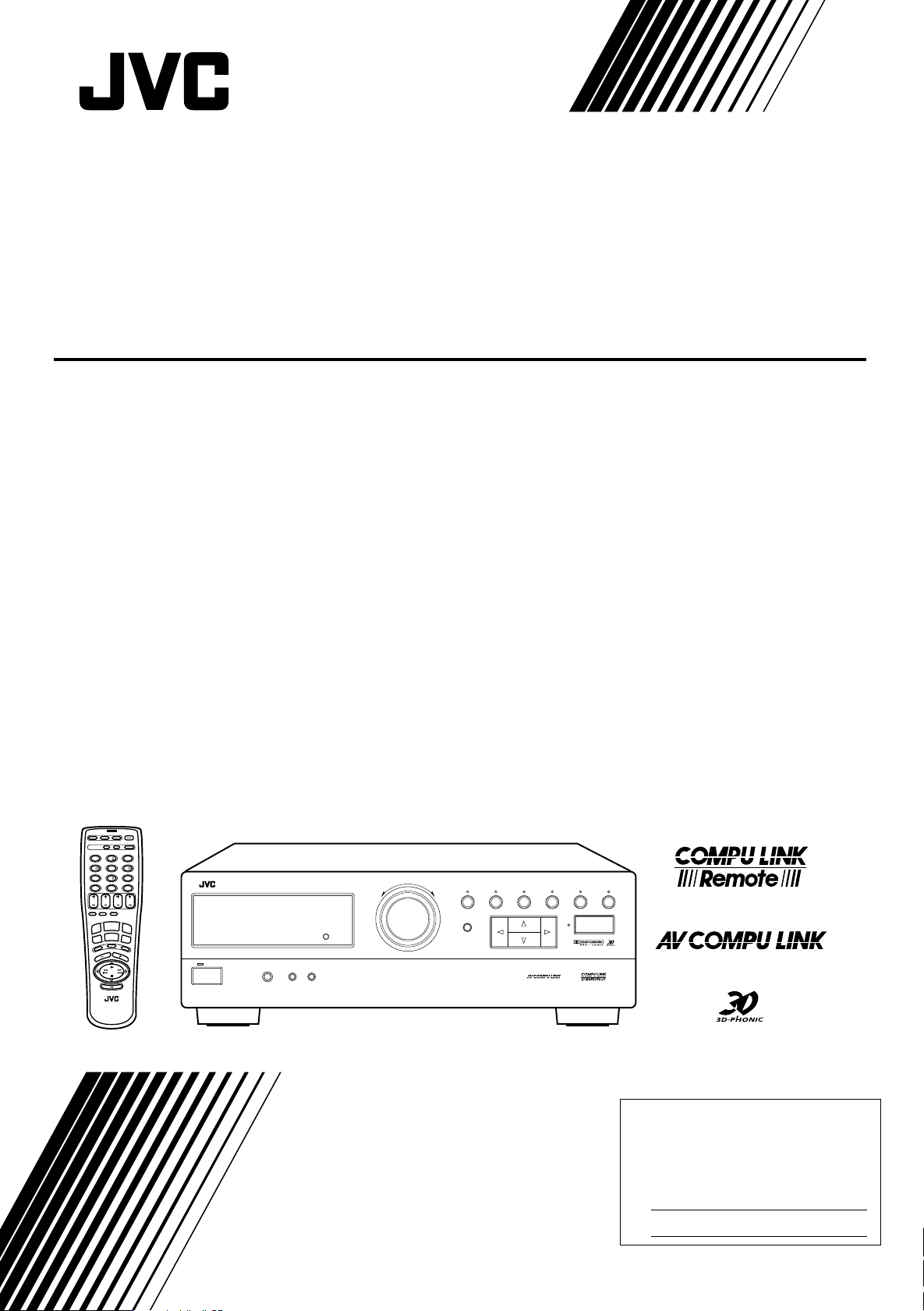
AUDIO/VIDEO CONTROL RECEIVER
RX-664VBK
POWER
CATV/SAT
TV
VCR AUDIO
SOUND
CATV
CD-DISC
CONTROL
CONTROL
DAP MODE 3D-PHONIC SURROUND
3
1
2
EFFECT DELAY TEST
6
5
4
SEA MODE SEA PRESET MENU
9
8
7/P
100+
RETURN/ENTER
– REAR•R +
0
10
+10
TV
REAR
CENTER
CH
VOLUME
(L)
TV/VIDEO
SLEEP
ONE TOUCH
OPERATION
CD
TAPE
TUNER/
BAND
VCR
TV
DVD
SOUND
MUTING
DVD MULTI
PHONO
VOLUME
RM-SR664U
REMOTE CONTROL
STANDBY
POWER
RX-664V AUDIO/VIDEO CONTROL RECEIVER
PHONES SPEAKERS
12
_ON —OFF
INSTRUCTIONS
DVD MULTI
MASTER VOLUME
–+
TUNER/BAND PRESET SEA SOURCE SURROUND ADJUST
MEMORY
SETTING
ONE TOUCH OPERATION
LET0119-001B
[J]
Page 2
Warnings, Cautions and Others
CAUTION
RISK OF ELECTRIC SHOCK
DO NOT OPEN
CAUTION: TO REDUCE THE RISK OF ELECTRIC SHOCK.
DO NOT REMOVE COVER (OR BACK)
NO USER SERVICEABLE PARTS INSIDE.
REFER SERVICING TO QUALIFIED SERVICE PERSONNEL.
The lightning flash with arrowhead symbol,
within an equilateral triangle is intended to
alert the user to the presence of uninsulated
"dangerous voltage" within the product's
enclosure that may be of sufficient
magnitude to constitute a risk of electric
shock to persons.
The exclamation point within an equilateral
triangle is intended to alert the user to the
presence of important operating and
maintenance (servicing) instructions in the
literature accompanying the appliance.
WARNING: TO REDUCE THE RISK OF FIRE
OR ELECTRIC SHOCK, DO NOT EXPOSE
THIS APPLIANCE TO RAIN OR MOISTURE.
CAUTION
To reduce the risk of electrical shocks, fire, etc.:
1. Do not remove screws, covers or cabinet.
2. Do not expose this appliance to rain or moisture.
Caution –– POWER switch!
Disconnect the mains plug to shut the power off completely. The
POWER switch in any position does not disconnect the mains line.
The power can be remote controlled.
G-1
Page 3
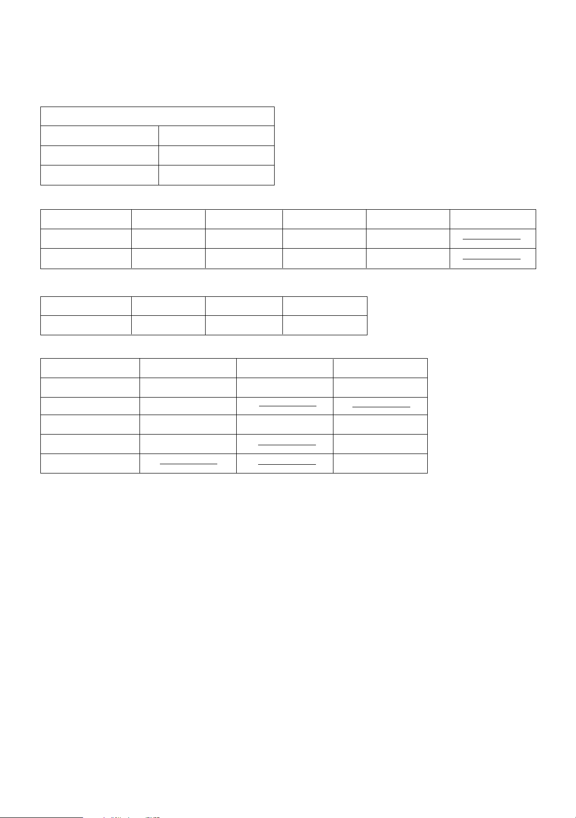
Once you have found the best DVD MULTI playback, DAP, 3D-PHONIC and Surround mode
settings for your listening room, note them in the table below for future reference (even though
the receiver memorizes the settings until you change them).
For actual setting procedures, see pages 26 to 39.
DVD MULTI Playback Mode
Center Speaker Level
Left Rear Speaker Level
Right Rear Speaker Level
DAP Mode Dance Club Live Club Hall Pavilion Headphones
Rear Speaker Level*
Effect Level
3D-PHONIC Mode 3D Action 3D Drama 3D Theater
Effect Level
Surround Mode Dolby Pro Logic Dolby 3ch Logic Theater Surround
Center Mode
Delay Time
Center Speaker Level
Rear Speaker Level*
Effect Level
* The left rear speaker level and right rear speaker level for DAP and the surround modes cannot be stored separately.
G-2
Page 4

Table of Contents
Parts Identification...................................................................................... 2
Easy Set Up & Operations ............................................................................ 3
Getting Started........................................................................................... 7
Before Installation...................................................................................................................................................................7
Checking the Supplied Accessories ........................................................................................................................................ 7
Connecting the FM and AM Antennas ................................................................................................................................... 8
Connecting the Speakers.........................................................................................................................................................9
Connecting Audio/Video Components ................................................................................................................................. 11
Connecting the Power Cord .................................................................................................................................................. 13
Putting Batteries in the Remote Control ............................................................................................................................... 13
Basic Operations ....................................................................................... 14
Turning the Power On and Off ............................................................................................................................................. 14
Selecting the Source to Play ................................................................................................................................................. 14
Adjusting the Volume ........................................................................................................................................................... 15
Selecting the Front Speakers.................................................................................................................................................15
Muting the Sound..................................................................................................................................................................15
Recording a Source ............................................................................................................................................................... 16
Listening with Headphones .................................................................................................................................................. 16
Basic Settings........................................................................................... 17
Adjusting the Front Speaker Output Balance ....................................................................................................................... 17
Listening at Low Volume (Loudness) ................................................................................................................................... 17
Using the Sleep Timer........................................................................................................................................................... 17
Selecting the Center Speaker Size ........................................................................................................................................ 19
One Touch Operation .................................................................................. 20
About the One Touch Operation ...........................................................................................................................................20
Using the One Touch Operation ...........................................................................................................................................20
Receiving Radio Broadcasts ........................................................................ 21
Tuning in Stations Manually................................................................................................................................................. 21
Using Preset Tuning.............................................................................................................................................................. 21
Selecting the FM Reception Mode ....................................................................................................................................... 23
Using the Preset SEA Modes...................................................................... 24
Selecting Your Favorite SEA Mode...................................................................................................................................... 24
Using the Surround Processor .................................................................... 26
Using JVC 3D-PHONIC Modes........................................................................................................................................... 27
Using the DAP Modes ..........................................................................................................................................................29
Speaker Arrangements for Surround Modes ......................................................................................................................... 32
Preparing for Surround Modes ............................................................................................................................................. 33
Using Surround Modes .........................................................................................................................................................37
Using the DVD MULTI Playback Mode .......................................................... 38
Speaker arrangements for DVD MULTI playback............................................................................................................... 38
Activating the DVD MULTI playback ................................................................................................................................. 38
COMPU LINK Remote Control System ......................................................... 40
AV COMPU LINK Remote Control System .................................................... 41
Operating Other Components ..................................................................... 43
Operating Other Manufacturers’ Video Equipment ........................................ 45
Troubleshooting......................................................................................... 48
Specifications............................................................................................ 49
1
Page 5
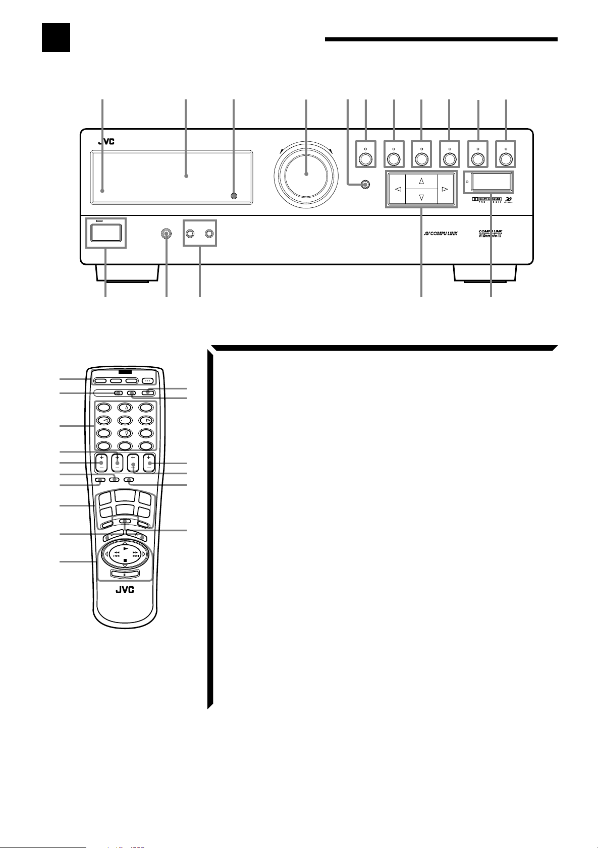
Parts Identification
Become familiar with the buttons and controls on the receiver before use.
$
%
^
&
*
(
)
_
+
¡
14
RX-664V AUDIO/VIDEO CONTROL RECEIVER
STANDBY
POWER
=
POWER
CATV/SAT
TV
VCR AUDIO
CATV
SOUND
CD-DISC
CONTROL
CONTROL
DAP MODE 3D-PHONIC
1
EFFECT DELAY TEST
4
SEA MODE SEA PRESET MENU
7/P
100+
– REAR•R +
+10
CENTER
ONE TOUCH
SLEEP
OPERATION
TUNER/
BAND
TV
SOUND
PHONO
REAR
(L)
2
5
0
TV/VIDEO
CD
VCR
MUTING
VOLUME
VOLUME
RETURN/ENTER
TV
DVD MULTI
SURROUND
3
6
98
10
CH
TAPE
DVD
2
PHONES SPEAKERS
12
_ON —OFF
~
!
™
£
¢
∞
§
¶
MASTER VOLUME
–+
DVD MULTI
Refer to the pages in parentheses for details.
Front Panel
1
Remote sensor (13)
2
Display (14)
3
DVD MULTI button (38)
4
MASTER VOLUME control (15)
5
MEMORY button (21)
6
TUNER/BAND button and lamp (21)
7
PRESET SEA button and lamp (24)
8
SOURCE button and lamp (14)
9
SURROUND button and lamp (27, 29)
0
ADJUST button and lamp (27, 29)
-
SETTING button and lamp (17)
=
POWER button and STANDBY lamp
(14)
~
PHONES jack (16)
!
SPEAKERS 1/2 buttons (15)
RM-SR664U
REMOTE CONTROL
@
Control % / fi / @ / # buttons
#
ONE TOUCH OPERATION button and
lamp (20)
6
53
TUNER/BAND PRESET SEA SOURCE SURROUND ADJUST
7
MEMORY
Remote Control
$
POWER buttons (CATV/SAT, TV, VCR,
AUDIO) (14, 45, 46, 47)
%
CATV CONTROL button (46)
^
10 keys/Sound control buttons
(22, 25, 28, 30, 35, 36, 37, 39)
&
REAR (L) butttons (+/–) (36, 39)
*
CENTER buttons (+/–) (36, 39)
(
ONE TOUCH OPERATION button (20)
)
SLEEP button (18)
_
Source buttons (TUNER/BAND, CD,
TAPE, TV SOUND, VCR, DVD,
PHONO, DVD MULTI) (14, 39, 43, 44,
45, 47)
+
VOLUME buttons (+/–) (15)
¡
Operating buttons for JVC audio/video
components (43, 44, 47)
™
SOUND CONTROL button (25, 28, 30,
35, 37, 39)
£
CD-DISC button (43)
¢
CH (Channel) buttons (+/–) (44, 45, 46,
8
@
9
0
ONE TOUCH OPERATION
#
47)
∞
TV VOLUME button (44, 45)
§
TV/VIDEO button (44, 45)
¶
MUTING button (15)
-
SETTING
2
Page 6
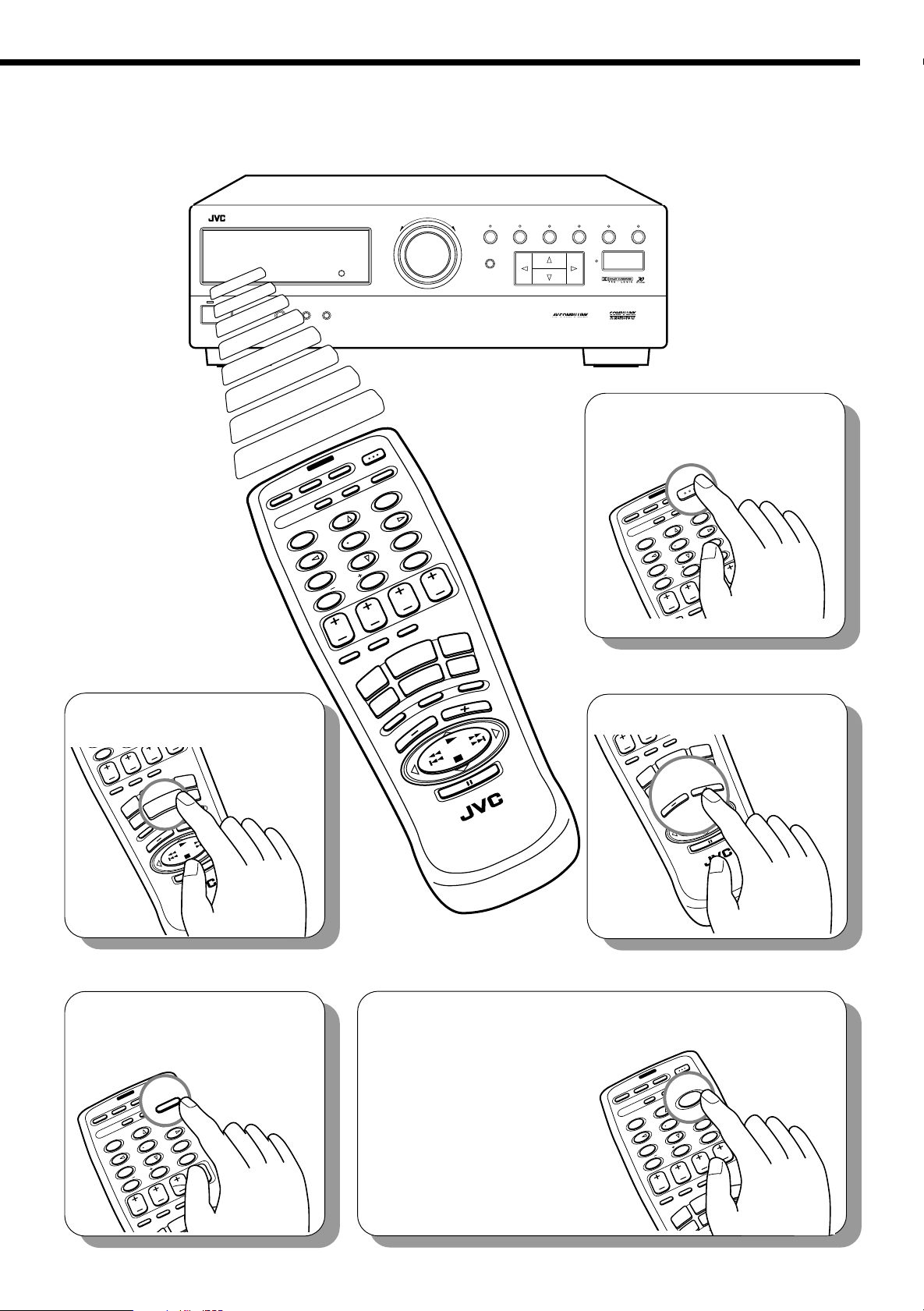
Easy Set Up & Operations
If you are already familiar with audio components, following four pages give you enough information to
operate your RX-664VBK for enjoyment of surround sound in your listening room.
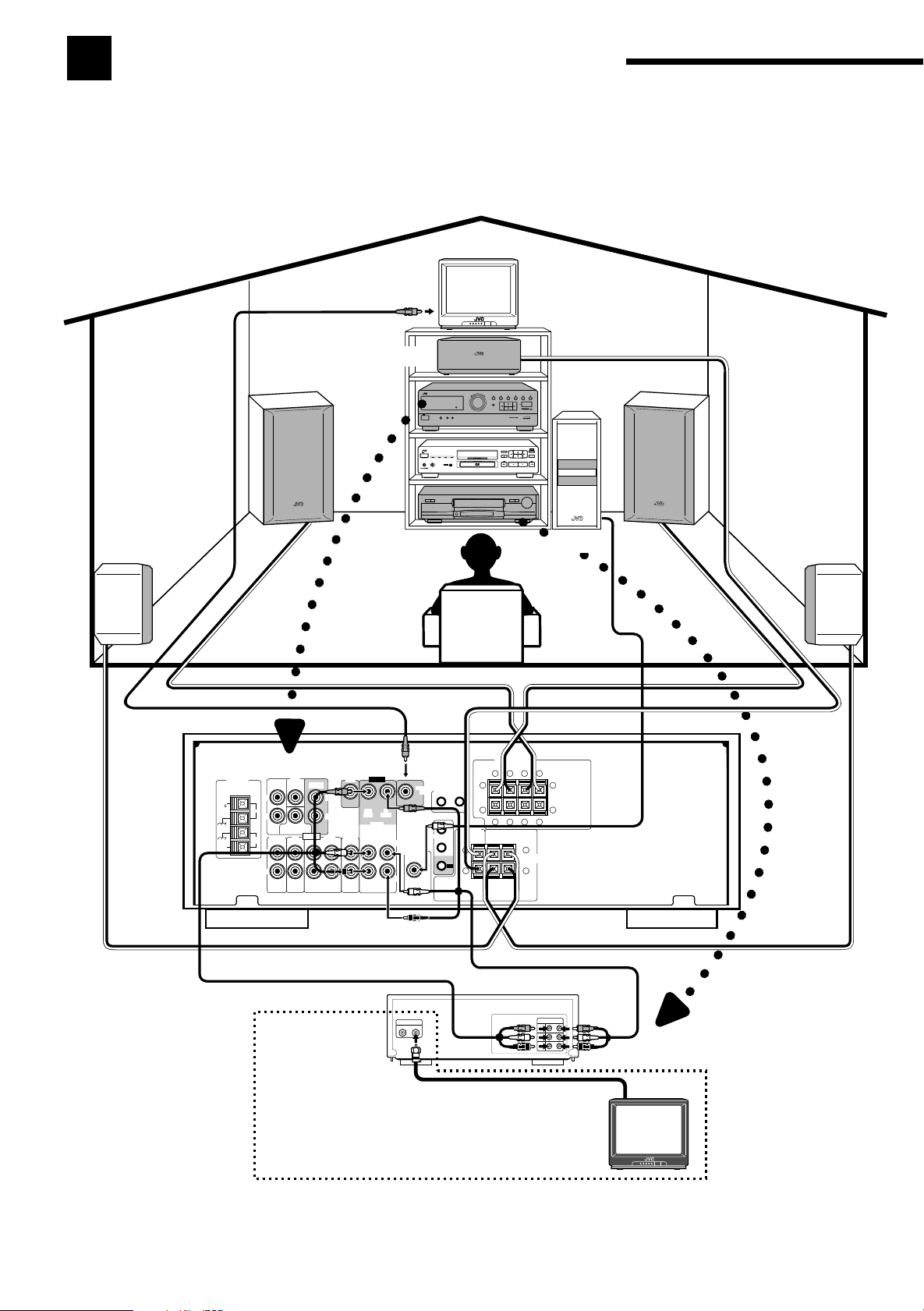
For Reproducing Surround Sound with your VCR
TV
To video input
Center Speaker
Front Speaker
RX-664V AUDIO/VIDEO CONTROL RECEIVER
Front Speaker
Rear Speaker
FM
75
GND
GND
AM
EXT
ANTENNA
Subwoofer
Rear Speaker
RX-664VBK
FRONT SPEAKERS
RIGHT LEFT
–
+
–
DVD
FRONT
CENTER
L
FM
R
SUBWOOFER
CD
PHONO
AM
LOOP
L
R
AUDIO
DVD
REAR
OUT
(REC)
VIDEO
MONITOR
LEFT
OUT
(REC)
RIGHT
VCR
OUT
TV
TAPE
SOUND
(REC)
IN
(PLAY)
OUT
IN
(PLAY)
AV
COMPU LINK
IN
(PLAY)
LEFT
SUBWOOFER
OUT
RIGHT
1
COMPU LINK-3
(SYNCHRO)
2
CENTER
SPEAKER
RIGHT LEFT
++
TV
––
+
+
–
–
+
REAR
SPEAKERS
1
2
To audio/video input
VCR
3
ANTENNA
IN OUT
To RF output
If your TV does not have a video input
OUT
IN
VIDEO
AUDIO
L
AUDIO
R
To TV antenna
input
To audio/video output
TV
Page 7
RX-664V AUDIO/VIDEO CONTROL RECEIVER
RE
L
)
DVD MULTI
MASTER VOLUME
–+
TUNER/BAND PRESET SEA SOURCE SURROUND ADJUST
MEMORY
SETTING
ONE TOUCH OPERATION
POWER
2
. Select the source.
100+
+10
CENTER
REAR
TUNER/
( L )
ONE TOUCH
OPERATION
BAND
SOUND
TV
PHONO
VOLUME
TV
TV/VIDEOSLEEP
TAPE
CD
DVD
VCR
VCR
DVD MULTI
MUTING
VOLUME
STANDBY
PHONES SPEAKERS
12
_ON —OFF
1
. Turn on the power.
AUDIO
VCR
CATV/SAT
DAP MODE
1
EFFECT
POWER
TV
CATV
CONTROL
4
SEA MODE
7/P
100+
3D-PHONIC
+10
CENTER
CD-DISC
2
DELAY
SEA PRESET
REAR.R
5
SOUND
CONTROL
SURROUND
8
REAR
( L )
ONE TOUCH
OPERATION
TUNER/
BAND
0
TV
SOUND
PHONO
3
TEST
6
MENU
9
RETURN/ENTER
TV
VOLUME
TV/VIDEOSLEEP
CD
10
VCR
MUTING
CH
VOLUME
TAPE
DVD
DVD MULTI
RM-SR664U
REMOTE CONTROL
AUDIO
AUDIO
VCR
POWER
SOUND
CONTROL
TV
CD-DISC
CATV
CONTROL
1
EFFECT
4
SEA MODE
100+
(
ONE TOUCH
OPERATION
BAND
SOUND
SURROUND
3
TEST
3D-PHONIC
6
2
MENU
DELAY
9
5
SEA PRESET
RETURN/ENTER
10
8
0
7/P
REAR.R
+10
CENTER
TV/VIDEOSLEEP
CD
VCR
MUTING
TV
VOLUME
VOLUME
PHONO
REAR
( L )
ONE TOUCH
PERATION
TAPE
TV
VOLUME
TV/VIDEO
DVD
DVD MULTI
CH
TAPE
CD
CATV/SAT
DAP MODE
3
. Adjust the volume.
CENTER
TUNER/
RM-SR664U
REMOTE CONTROL
4
. Set the remote control
to sound operation
mode.
AUDIO
VCR
POWER
SOUND
SOUND
CONTROL
TV
EFFECT
1
CATV
CONTROL
4
SEA MODE
100+
CONTROL
CD-DISC
SURROUND
3
TEST
3D-PHONIC
6
2
MENU
DELAY
9
5
SEA PRESET
RETURN/ENTER
10
8
0
7/P
REAR.R
+10
CENTER
REAR
( L )
ONE TOUCH
OPERATION
VOLUME
CH
TV
TV/VIDEOSLEEP
CD
CATV/SAT
DAP MODE
RM-SR664U
REMOTE CONTROL
5
. Surround settings are
preset at the factory.
However, if you need to
make further
adjustments, see pages
CATV/SAT
DAP MODE
26 to 37.
TAPE
DVD
EFFECT
TV
1
SEA MODE
POWER
CATV
CONTROL
4
7/P
100+
+10
VCR
3D-PHONIC
CENTER
CD-DISC
2
DELAY
REAR.R
5
SEA PRESET
AUDIO
SOUND
CONTROL
SURROUND
SURROUND
3
3
8
0
REAR
( L )
ONE TOUCH
OPERATION
TUNER/
BAND
TV
OUND
TEST
6
MENU
RETURN/ENTER
VOLUME
9
10
CH
TV
TV/VIDEOSLEEP
TAPE
CD
DVD
VCR
DVD MULTI
MUTING
UME
4
Page 8
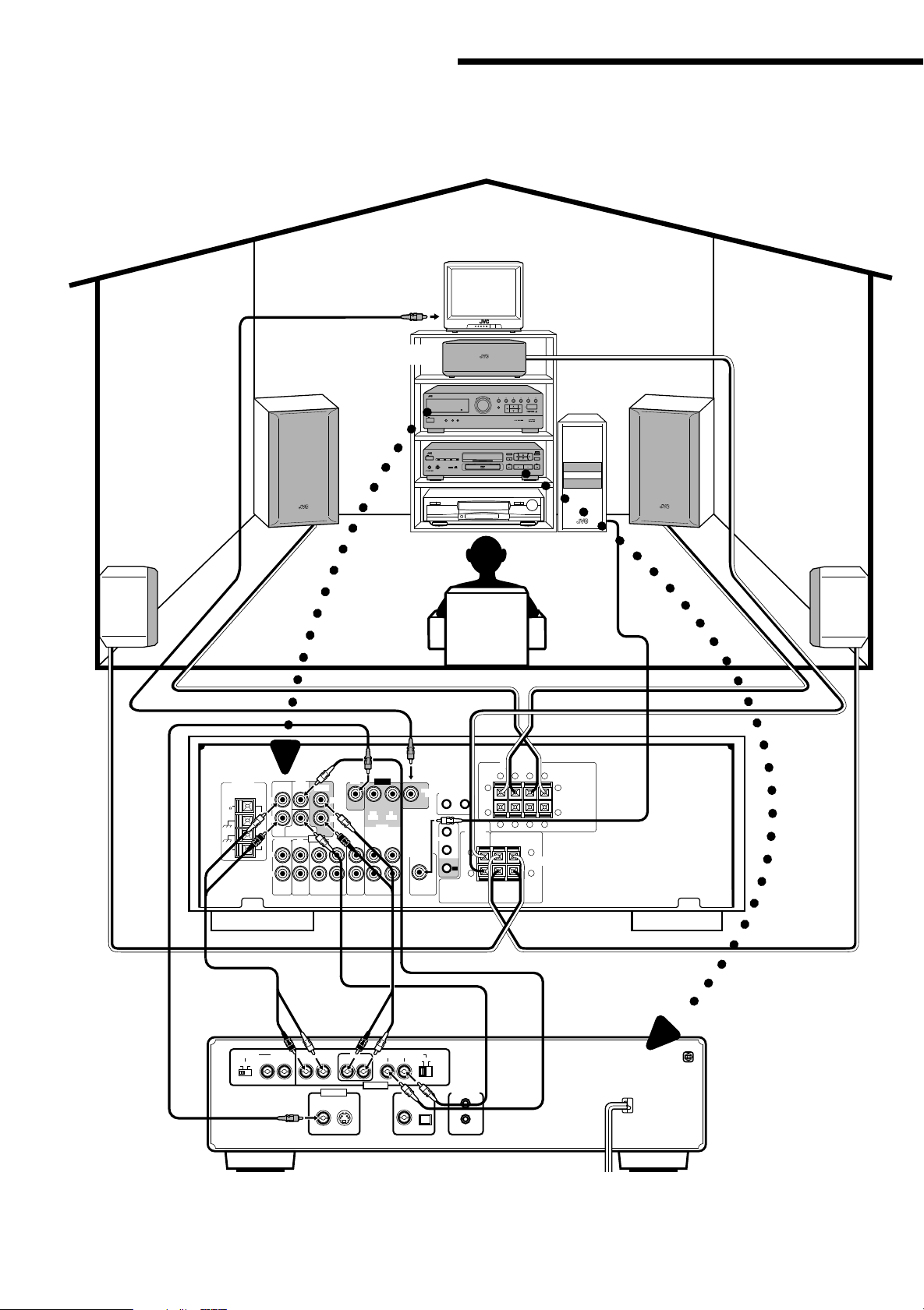
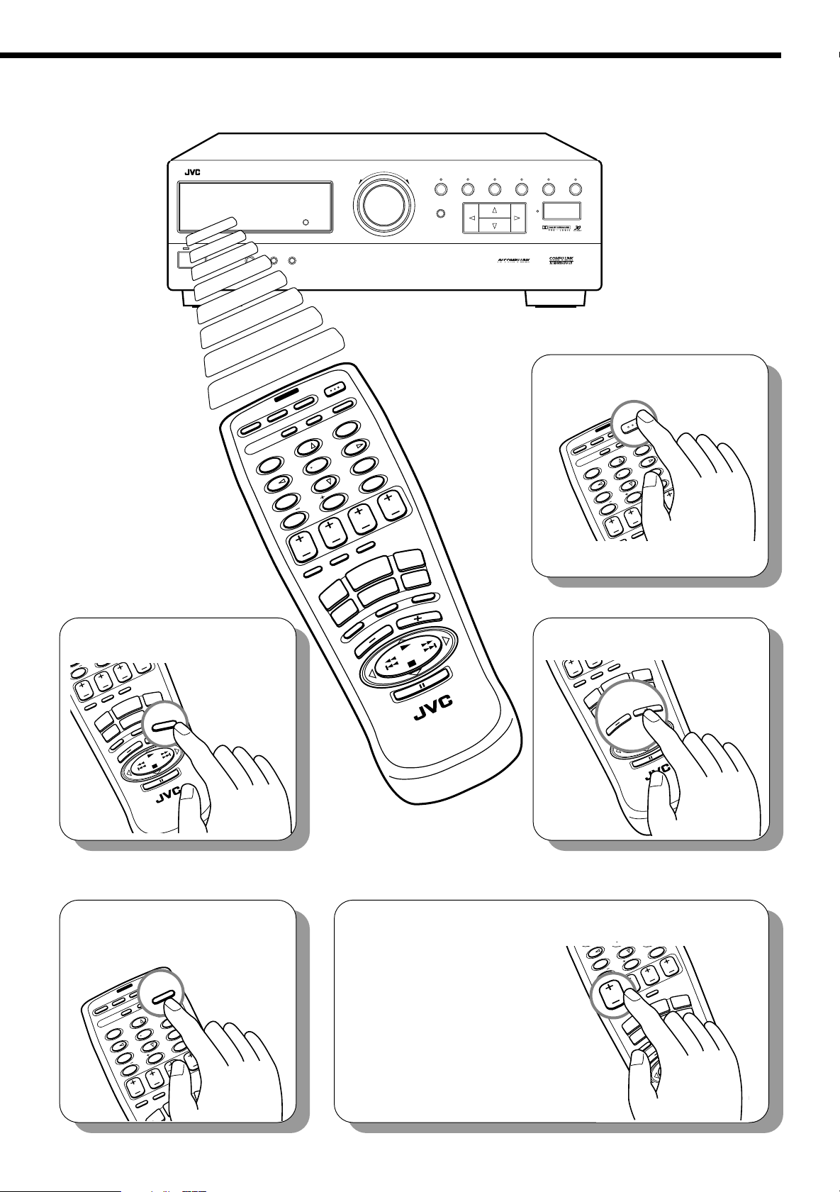
Easy Set Up & Operations
For Reproducing DVD MULTI Playback with your DVD player
TV
To video input
Center Speaker
Rear Speaker
Front Speaker
ANTENNA
FM
75
FM
GND
GND
AM
LOOP
AM
EXT
FRONT CENTER
L
R
PHONO
L
R
DVD
SUBWOOFER
CD
AUDIO
RX-664V AUDIO/VIDEO CONTROL RECEIVER
Front Speaker
Subwoofer
Rear Speaker
RX-664VBK
FRONT SPEAKERS
RIGHT LEFT
+
–
–
DVD
LEFT
RIGHT
TAPE
VIDEO
MONITOR
OUT
OUT
IN
(REC)
(PLAY)
VCR
OUT
TV
SOUND
(REC)
IN
(PLAY)
AV
COMPU LINK
IN
(PLAY)
LEFT
SUBWOOFER
OUT
RIGHT
1
COMPU LINK-3
(SYNCHRO)
2
CENTER
SPEAKER
RIGHT LEFT
++
TV
––
REAR
OUT
(REC)
+
+
–
–
+
REAR
SPEAKERS
1
2
5
To video
output
To front left/
right channel
audio output
ATTENUATOR 2CH
ON
OFF
To rear left/
right channel
audio output
RIGHT LEFTRIGHT LEFT
VIDEO OUT
VIDEO S-VIDEO
REARFRONT
RIGHT LEFT
AUDIO OUT
CENTER
SUBWOOFER
NORMAL
PCM/DOLBY DIGITAL
To
subwoofer
audio output
GAIN PLUS
OPTICALCOAXIAL
AV COMPU LINKDIGITAL OUT
To center
channel
audio output
DVD Player
1
Page 9
7/P
0
H
EAR.
RE
L
)
RX-664V AUDIO/VIDEO CONTROL RECEIVER
1
5
R
9
DVD MULTI
MASTER VOLUME
–+
TUNER/BAND PRESET SEA SOURCE SURROUND ADJUST
MEMORY
SETTING
ONE TOUCH OPERATION
POWER
2
. Select the source.
REAR
( L )
ONE TOUCH
OPERATION
TUNER/
BAND
SOUND
TV
PHONO
VOLUME
C
TV
TV/VIDEOSLEEP
TAPE
CD
DVD
VCR
DVD MULTI
DVD MULTI
MUTING
VOLUME
R
0+
+10
CENTER
STANDBY
PHONES SPEAKERS
CATV/SAT
DAP MODE
12
_ON —OFF
POWER
TV
CATV
CONTROL
1
EFFECT
4
SEA MODE
7/P
100+
VCR
CD-DISC
3D-PHONIC
+10
CENTER
2
DELAY
5
SEA PRESET
REAR.R
AUDIO
SOUND
CONTROL
SURROUND
8
0
REAR
( L )
ONE TOUCH
OPERATION
TUNER/
BAND
3
TEST
TV
SOUND
PHONO
6
MENU
9
RETURN/ENTER
10
TV
VOLUME
TV/VIDEOSLEEP
CD
VCR
MUTING
CH
VOLUME
TAPE
DVD
DVD MULTI
RM-SR664U
REMOTE CONTROL
1
. Turn on the power.
AUDIO
AUDIO
VCR
POWER
SOUND
CONTROL
TV
CD-DISC
CATV
CONTROL
1
EFFECT
4
SEA MODE
(
ONE TOUCH
OPERATION
BAND
SOUND
100+
TV
PHONO
SURROUND
3
TEST
3D-PHONIC
6
2
MENU
DELAY
9
5
SEA PRESET
RETURN/ENTER
10
8
0
7/P
REAR.R
+10
CENTER
TV/VIDEOSLEEP
CD
VCR
MUTING
VOLUME
VOLUME
REAR
( L )
ONE TOUCH
OPERATION
TAPE
DVD
DVD MULTI
VOLUME
CH
TV
TV/VIDEOSLEEP
TAPE
CD
CATV/SAT
DAP MODE
3
. Adjust the volume.
CENTER
TUNER/
DVD
RM-SR664U
REMOTE CONTROL
RM-SR664U
REMOTE CONTROL
4
. Set the remote control
to sound operation
mode.
AUDIO
VCR
POWER
SOUND
SOUND
CONTROL
TV
CONTROL
CD-DISC
CATV
EFFECT
1
CONTROL
4
SEA MODE
100+
SURROUND
3
TEST
3D-PHONIC
6
2
MENU
DELAY
9
5
SEA PRESET
RETURN/ENTER
10
8
0
7/P
REAR.R
+10
CENTER
REAR
( L )
ONE TOUCH
UNER/
OPERATION
ND
VOLUME
CH
TV
TV/VIDEOSLEEP
TAPE
CD
DVD
VCR
DVD MULTI
DAP MODE
CATV/SAT
5
. Surround settings are
preset at the factory.
However, if you need to
make further
adjustment, see pages
38 and 39.
EFFECT
4
SEA MODE
100+
SEA PRESET
RETURN/ENTE
10
8
0
7/P
REAR.R
+10
CENTER
CENTER
REAR
( L )
ONE TOUCH
TUNER/
BAND
OPERATION
TV
SOUND
PHONO
VOLUME
CH
TV
TV/VIDEOSLEEP
TAPE
CD
DVD
VCR
DVD MULTI
MUTING
VOLUME
RM-SR664U
REMOTE CONTROL
6
Page 10

Getting Started
This section explains how to connect stereo components and speakers to the receiver, and how to connect
the power supply.
Before Installation
General
• Be sure your hands are dry.
• Turn the power off to all components.
• Read the manuals supplied with the components you are going to connect.
Locations
• Install the receiver in a location that is level and protected from moisture.
• The temperature around the receiver must be between 23˚ and 95˚ F
(–5˚ and 35˚ C).
• Make sure there is good ventilation around the receiver. Poor ventilation could cause
overheating and damage the receiver.
Handling the receiver
• Do not insert any metal object into the receiver.
• Do not disassemble the receiver or remove screws, covers, or cabinet.
• Do not expose the receiver to rain or moisture.
Checking the Supplied Accessories
Check to be sure you have all of the following items, which are supplied with the
receiver.
The number in the parentheses indicates quantity of the pieces supplied.
• Remote Control (1)
• Batteries (2)
• AM Loop Antenna (1)
• FM Antenna (1)
If anything is missing, contact your dealer immediately.
7
Page 11
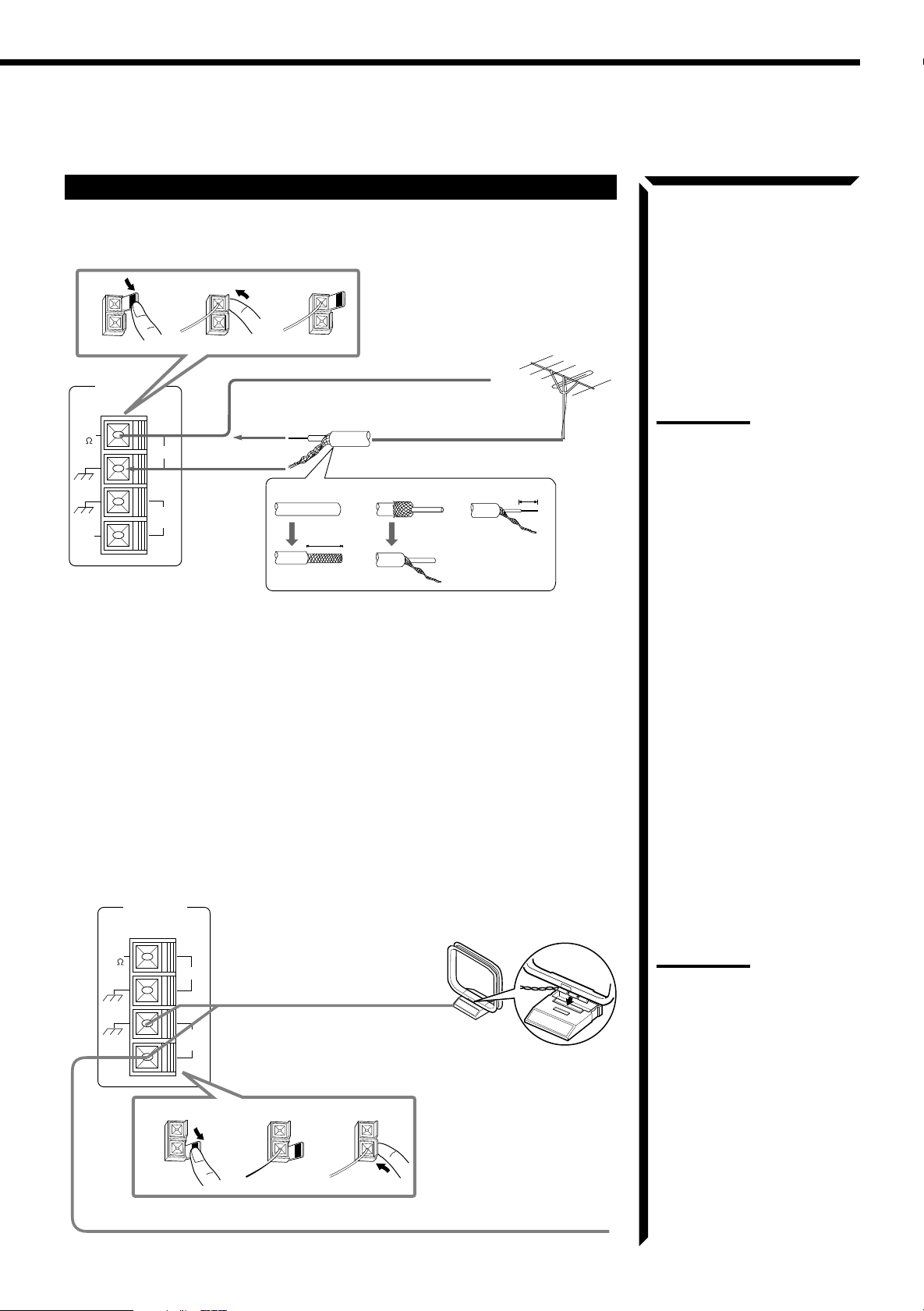
Connecting the FM and AM Antennas
FM Antenna Connections
231
FM Antenna
ANTENNA
FM
75
GND
GND
AM
EXT
FM
AM
LOOP
Extend the FM antenna horizontally.
1
13/16 in.
(20 mm)
Outside FM Antenna Cable
7/16 in.
2
3
(10 mm)
Note:
If reception is poor, connect the
outside antenna.
Before attaching a 75 Ω coaxial
cable (the kind with a round wire
going to an outside antenna),
disconnect the supplied FM wire
antenna.
How to strip the 75 Ω coaxial cable and connect it to the FM
terminals
1. Strip back the outside covering of the 75 Ω coaxial cable to expose the braided
metallic mesh about 13/16 inches (20 mm).
2. Pull the mesh back and twist it into a single connector as shown in the illustration
above.
3. Strip the insulation about 7/16 inches (10 mm) back from the central wire.
4. Insert the twisted mesh and the central wire to the FM terminals, as shown in the
illustration above.
AM Antenna Connections
ANTENNA
FM
75
GND
GND
AM
EXT
FM
AM
LOOP
1
AM Loop Antenna
23
Turn the loop until you have
the best reception.
Snap the tabs on the loop into
the slots of the base to assemble
the AM loop.
Notes :
•
Make sure the antenna
conductors do not touch any
other terminals, connecting
cords and power cord. This
could cause poor reception.
•
If reception is poor, connect an
outdoor single vinyl-covered
wire to the AM EXT terminal.
(Keep the AM loop antenna
connected.)
Outdoor Single Vinylcovered Wire
8
Page 12
Getting Started
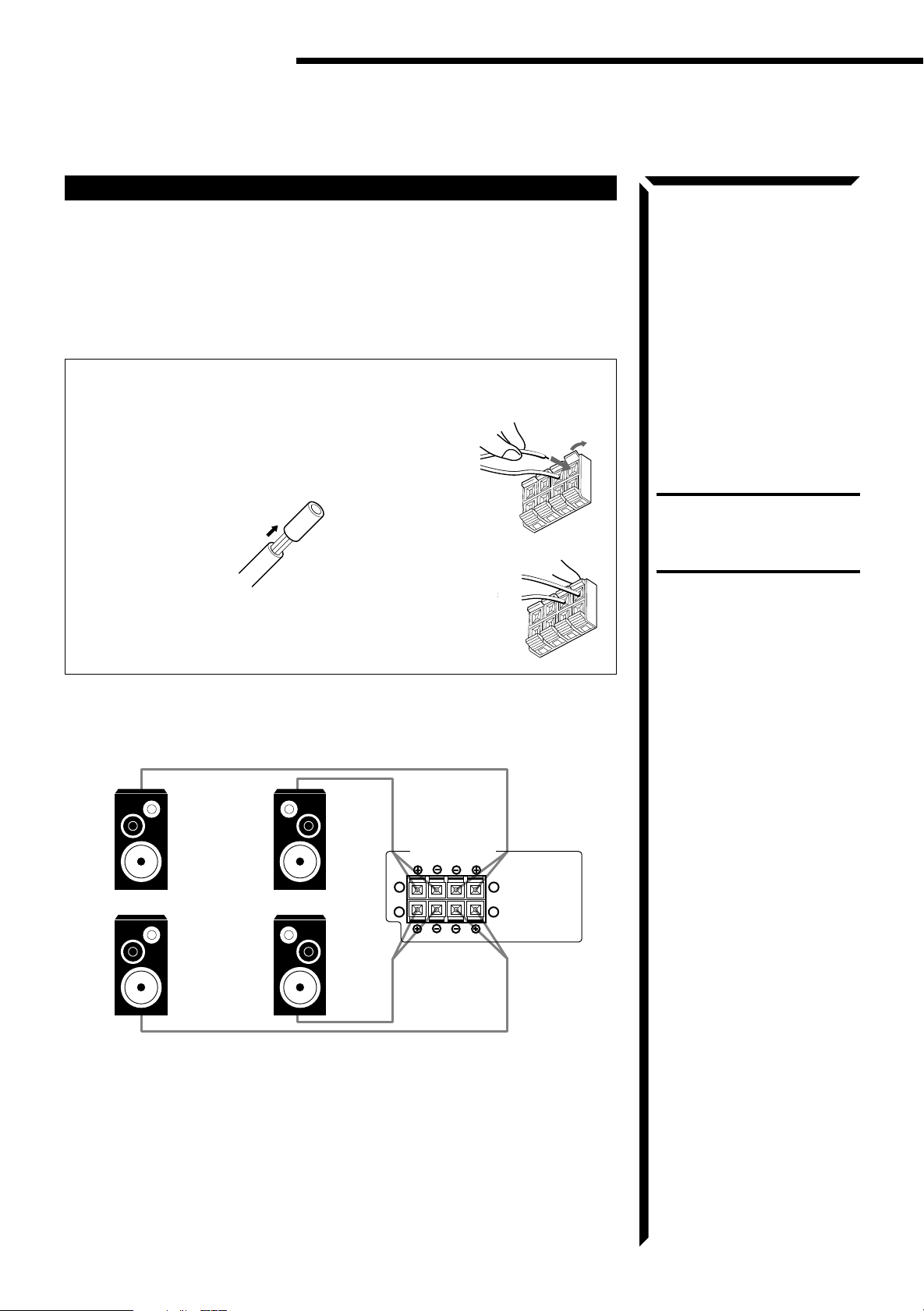
Connecting the Speakers
You can connect the following speakers:
• Two sets of front speakers to produce normal stereo sound
• One set of rear speakers to enjoy the surround effect
• One center speaker to produce more effective surround effect (to make human
voices outstanding)
• One subwoofer to enhance the bass
For each speaker (except for subwoofer), connect one end of the speaker signal
cable (not supplied) to the speaker terminal on the rear panel and the other end to
the speaker. (For connecting a subwoofer, see page 10.)
1. Open each terminal.
2. Insert the end of the speaker signal cable as shown (be
sure to remove the insulation at the end of each wire
first).
CAUTION:
When connecting speakers, use
speakers with the SAME
IMPEDANCE indicated by the
speaker terminals.
3. Close the terminals to clamp the speaker signal cables
firmly in place.
4. Connect the (–) and (+) terminals on the rear panel to
the (–) and (+) terminals marked on the speakers.
Connecting the front speakers
Connect the front speakers to the FRONT SPEAKERS terminals.
Left speaker
SPEAKERS 1
Right speaker
SPEAKERS 2
FRONT SPEAKERS
RIGHT LEFT
1
2
1
2
9
Page 13
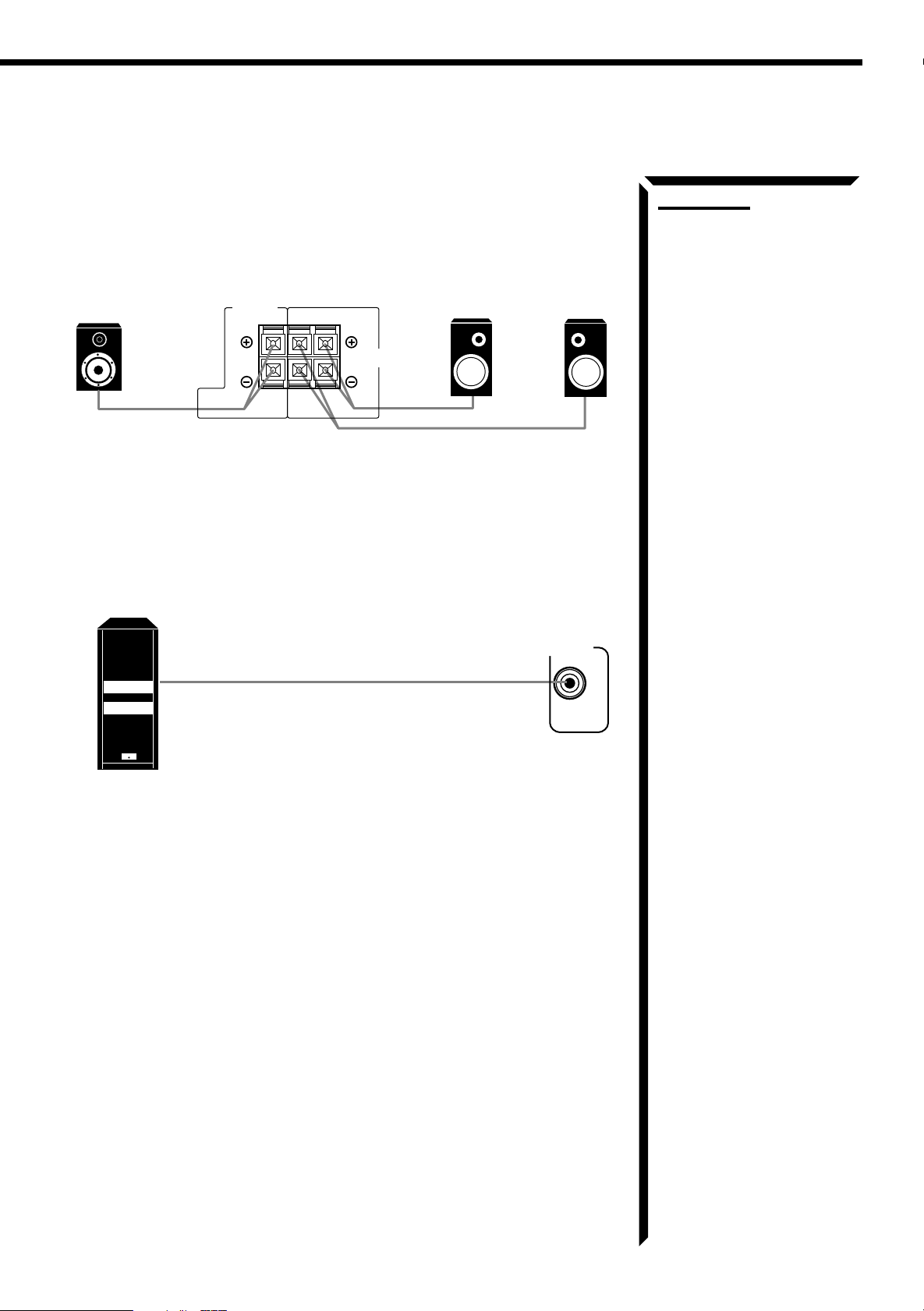
Connecting the rear and center speakers
Connect the rear speakers to the REAR SPEAKERS terminals and the center speaker to
the CENTER SPEAKER terminals.
Center
speaker
CENTER
SPEAKER
RIGHT LEFT
REAR
SPEAKERS
Left rear
speaker
Right rear
speaker
Connecting the subwoofer
Connect the input jack of a powered subwoofer to the SUBWOOFER OUT jack on the
rear panel, using a cable with RCA pin plugs.
Notes:
•
When you connect rear
speakers, make sure that both
left and right speakers are
connected; otherwise, no
sound will come out of the rear
speakers.
•
You can register the center
speaker size after you finish its
connection. If you register it,
you do not have to set the
center speaker mode while
setting the surround mode. (If
you do not use a center
speaker, register that
information.) See page 19.
Powered subwoofer
SUBWOOFER
OUT
10
Page 14
Getting Started
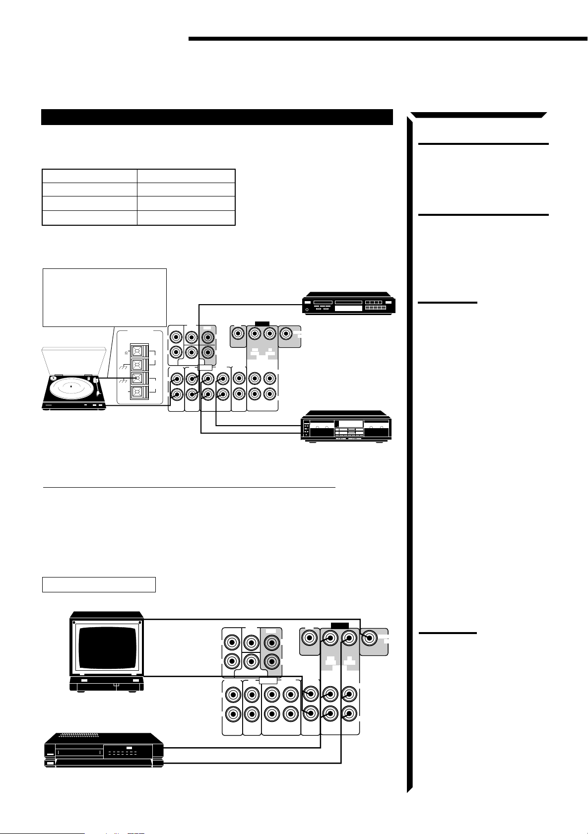
Connecting Audio/Video Components
You can connect the following components to the receiver using cables with RCA pin
plugs.
Audio Components Video Components
• Turntable • TV
• CD player • VCR
• Cassette deck • DVD player
Audio component connections
If a ground cable is provided
for your turntable, connect the
cable to the GND terminal of
the AM LOOP terminals on the
rear panel.
ANTENNA
FM
Turntable
75
GND
GND
AM
EXT
To audio
output
FM
AM
LOOP
L
R
PHONO
L
R
FRONT
DVD
CENTER
SUBWOOFER
CD
REAR
AUDIO
OUT
(REC)
To audio output
DVD
LEFT
RIGHT
TAPE
(PLAY)
(REC)
TV
(REC)
SOUND
IN
To audio output
To audio input
VIDEO
OUT
VCR
OUT
(PLAY)
(PLAY)
MONITOR
OUT
IN
IN
LEFT
RIGHT
CD player
Cassette deck
CAUTION:
If you connect a sound-enhancing
device such as a graphic equalizer
between the source components
and this receiver, the sound output
through this receiver may be
distorted.
Note:
Any turntables incorporating a
small-output cartridge such as an
MC (moving-coil type) must be
connected to the receiver through
a commercial head amplifier or
step-up transformer. Direct
connection may result in
unsufficient volume.
If your audio components have a COMPU LINK-3 terminal
The COMPU LINK remote control system allows you to control other JVC audio
components from the receiver or vice versa.
For detailed information about the COMPU LINK-3 remote control system, see page
40.
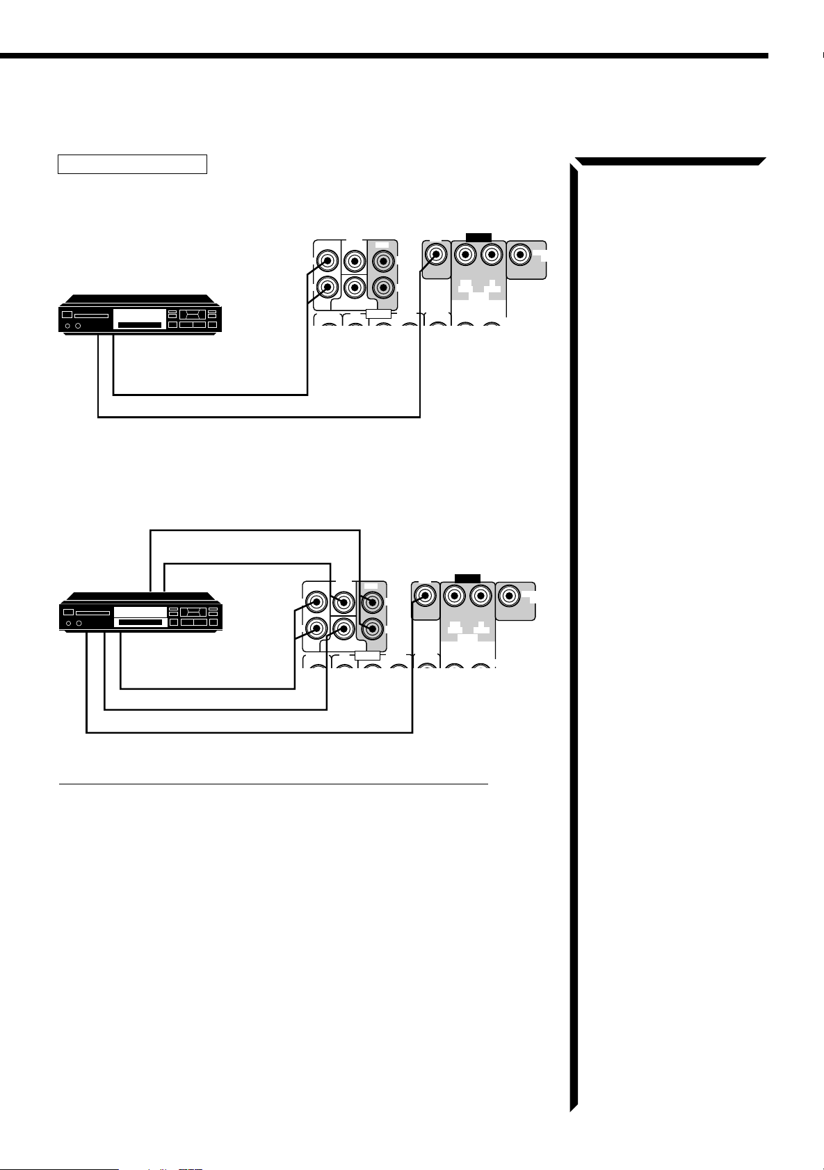
Video component connections
TV and VCR connection
To video input (see note to the right)
DVD
CENTER
TV
To audio output
FRONT
L
R
PHONO
L
R
SUBWOOFER
CD
REAR
AUDIO
(REC)
LEFT
RIGHT
TAPE
SOUND
OUT
IN
(PLAY)
To audio/video input
VHS
VCR
To audio/video output
DVD
VIDEO
OUT
IN
(REC)
(PLAY)
VCR
OUT
(REC)
(PLAY)
IN
LEFT
RIGHT
TV
MONITOR
OUT
Note:
When connecting a JVC TV:
•
If you use the A V COMPU LINK
remote control system to
operate the TV, connect the
receiver to the Video Input 2
jack on the TV.
•
If you do not use the AV
COMPU LINK remote control
system to operate the TV,
connect the receiver to the
Video Input 1 jack on the TV.
11
Page 15
DVD player connection
• When you play back a disc on the DVD player in stereo (or the audio output setting of
the DVD player is mixed to two front channels):
DVD
VIDEO
MONITOR
OUT
IN
(REC)
(PLAY)
VCR
OUT
(REC)
(PLAY)
IN
LEFT
RIGHT
TV
DVD player
DVD
To front left/right channel
audio output (or to audio
mixed output if necessary)
To video output
FRONT
L
R
PHONO
L
R
DVD
CENTER
SUBWOOFER
CD
REAR
AUDIO
(REC)
LEFT
RIGHT
TAPE
SOUND
OUT
IN
(PLAY)
• When you play back a disc on the DVD player with its analog discrete output mode (5.1
CH reproduction) selected:
To rear left/right channel audio output
To center channel audio output
OUT
DVD player
DVD
To front left/right channel
audio output
To subwoofer audio output
To video output
L
R
PHONO
L
R
FRONT
DVD
CENTER
SUBWOOFER
CD
REAR
AUDIO
(REC)
LEFT
RIGHT
TAPE
SOUND
OUT
IN
(PLAY)
DVD
VIDEO
MONITOR
OUT
IN
(REC)
(PLAY)
VCR
OUT
(REC)
(PLAY)
IN
LEFT
RIGHT
TV
If your audio components have an AV COMPU LINK terminal
The AV COMPU LINK remote control system allows you to control other JVC video
components from the receiver or vice versa.
For detailed information about the connection and the AV COMPU LINK remote
control system, see page 41.
OUT
12
Page 16
Getting started
Connecting the Power Cord
Before plugging the receiver into an AC outlet, make sure that all connections have
been made.
When the power cord is connected, the STANDBY lamp above the POWER button
lights up.
Keep the power cord away from the connecting cables for the TV, VCR, and antenna.
The power cord may cause noise or screen interference. We recommend that you use a
coaxial cable to connect the antenna, since it is well-shielded against interference.
Putting Batteries in the Remote Control
Before using the remote control, put the two supplied batteries in first. When using the
remote control, aim the remote control directly at the remote sensor on the receiver.
Notes:
•
A small amount of power is
always consumed even in
standby mode. T o switch of f the
power completely, unplug the
power cord from the AC outlet.
•
If the power cord is unplugged
(or a power failure occurs),
preset settings will be erased in
a few days.
CAUTIONS:
• Do not touch the power cord
with wet hands.
• Do not pull on the power cord
to unplug the receiver. When
unplugging the receiver, always
grasp the plug itself so as not
to damage the cord.
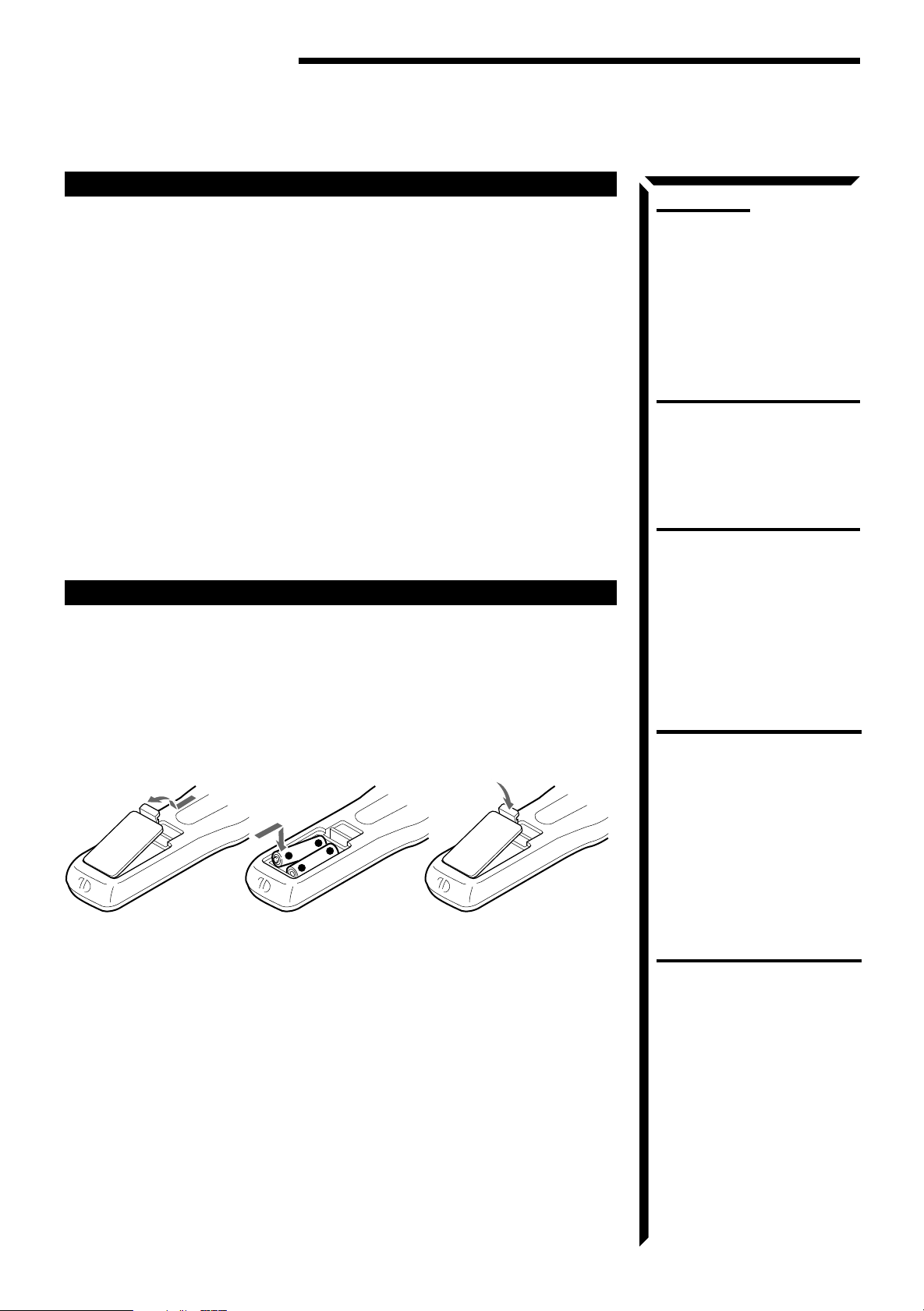
1. On the back of the remote control, remove the battery cover as illustrated.
2. Insert batteries. Make sure to observe the proper polarity: (+) to (+) and (–)
to (–).
3. Replace the cover.
R6P (SUM-3)/AA (15F)
+
+
-
If the range or effectiveness of the remote control decreases, replace the batteries. Use
two R6P (SUM-3)/AA (15F) type dry-cell batteries.
CAUTIONS:
Follow these precautions to avoid
leaking or cracking cells:
• Place batteries in the remote
control so they match the
polarity indicated: (+) to (+) and
(–) to (–).
• Use the correct type of batteries.
Batteries that look similar may
differ in voltage.
• Always replace both batteries at
the same time.
• Do not expose batteries to heat
or flame.
13
Page 17
Basic Operations
STANDBY
POWER
The following operations are commonly used when you play any sound source.
Turning the Power On and Off
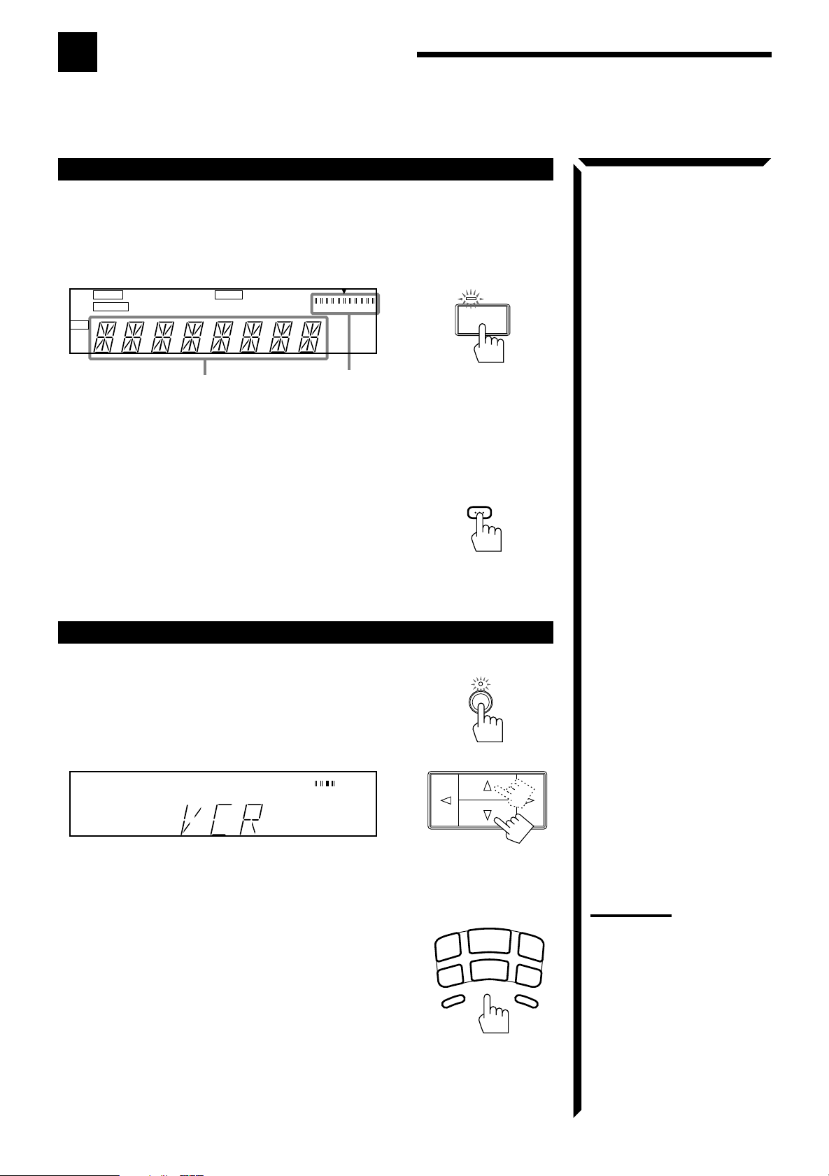
On the front panel:
To turn on the power, press POWER.
The STANDBY lamp goes off. The name of the current
source (or station frequency) appears on the display.
MUTE TUNED SLEEP SEA 3D-PHONIC
AUTO STEREO PRO LOGIC 3CH LOGIC HALL LOUDNESS
DAP
CH-
L
VOLUME
MHz
kHz
Current source name appears Current volume
level is shown here
To turn off the power, press POWER again.
The STANDBY lamp lights up.
From the remote control:
To turn on the power, press AUDIO.
The STANDBY lamp goes off. The name of the current
source (or station frequency) appears on the display.
To turn off the power, press AUDIO again.
The STANDBY lamp lights up.
Selecting the Source to Play
On the front panel:
%%
1. Press SOURCE so that the Control
work for selecting the source.
The lamp above the button lights up.
%%
2. Press Control
fifi
% /
fi until the source name you want
%%
fifi
appears on the display.
fifi
% /
fi buttons
%%
fifi
VOLUME
R
AUDIO
SOURCE
From the remote control:
Press one of the source buttons directly.
TUNER/BAND* Listen to the radio.
Each time you press the button, the band
alternates between FM and AM.
CD* Listen to the CD player.
TAPE* Listen to the cassette deck.
TV SOUND Listen to TV sounds.
VCR View the playback picture from the VCR.
DVD Play back a stereo digital video disc.
PHONO* Listen to a record.
DVD MULTI Play back a digital video disc using the
analog discrete output mode (5.1 CH
reproduction) on the DVD player.
TUNER/
BAND
TV
SOUND
PHONO
CD
VCR
TAPE
DVD
DVD MULTI
Notes:
• When you press one of the
source buttons on the remote
control marked with an asterisk
(*), the receiver automatically
turns on.
• When connecting this receiver
and the DVD player by using
the AV COMPU LINK cable,
“DVD MULTI” is always
selected when you start playing
a disc of 5.1 ch surround. You
can change it to “DVD” after
playback starts.
14
Page 18

MUTING
Basic Operations
Adjusting the Volume
On the front panel:
To increase the volume, turn MASTER VOLUME
clockwise.
To decrease the volume, turn it counterclockwise.
When you turn MASTER VOLUME rapidly, the volume
level also changes rapidly.
When you turn MASTER VOLUME slowly, the volume
level also changes slowly.
From the remote control:
To increase the volume, press VOLUME +.
To decrease the volume, press VOLUME –.
MASTER VOLUME
–+
VOLUME
CAUTION:
Always set the volume to the
minimum before starting any
source. If the volume is set at its
high level, the sudden blast of
sound energy can permanently
damage your hearing and/or ruin
your speakers.
Note:
The volume level can be adjusted
within the range of “0” (minimum)
to “62” (maximum).
Selecting the Front Speakers
On the front panel
only
:
When you have connected two sets of front speakers, you
can select which to use. Pressing SPEAKERS 1 or
SPEAKERS
12
_ON —OFF
SPEAKERS 2 activiates the respective set of speakers.
To use the set of speakers connected to the FRONT SPEAKERS 1 terminals, press
SPEAKERS 1 to set it in the _ON position, and press SPEAKERS 2 to set it in the —
OFF position.
To use the set of speakers connected to the FRONT SPEAKERS 2 terminals, press
SPEAKERS 2 to set it in the _ON position, and press SPEAKERS 1 to set it in the —
OFF position.
To use both set of speakers, press both SPEAKERS 1 and 2 to set them in the _ON
position.
To use neither set of speakers, press both SPEAKERS 1 and 2 to set them in the —
OFF position.
Muting the Sound
From the remote control
only
:
Press MUTING to turn off the sound through all
speakers and headphones connected.
“MUTE” appears on the display and the volume turns off.
Notes:
• When only one set of the front
speakers is connected to either
the FRONT SPEAKERS 1 or
2
terminals, do not press both
SPEAKERS 1 and 2 to set them
_
in the
no sound comes out of the front
speakers.
• The SPEAKERS 1 and 2
buttons do not affect the sound
output of the center and rear
speakers.
ON position. If you do,
To restore the sound, press MUTING again.
Turning MASTER VOLUME or pressing VOLUME +/– also restores the sound.
15
Page 19

Recording a Source
You can record any source playing through the receiver to a cassette deck connected to
the TAPE jacks and the VCR connected to the VCR jacks at the same time.
While recording, you can listen to the selected sound source at whatever sound level
you like, without affecting the sound levels of the recording.
Listening with Headphones
A standard pair of headphones can be connected to the
PHONES jack on the front panel. Be sure to turn down
the volume before connecting or putting on headphones,
as high volume can damage both the headphones and
your hearing.
To listen with only headphones
Press both SPEAKERS 1 and 2 to set them in the —OFF position.
SPEAKERS
12
_ON —OFF
Note:
The following sound modes
cannot affect the recording.
• Preset SEA modes: (see page
24)
• 3D-PHONIC modes: (see page
27)
• DAP modes: (see page 29)
• DVD MULTI playback mode:
(see page 38)
Note:
The SPEAKERS 1 and 2 buttons
do not affect the sound output of
the center and rear speakers.
16
Page 20

Basic Settings
Some of the following settings are required after connecting and positioning your speakers in your listening
room, while others will make operations easier.
Adjusting the Front Speaker Output Balance
If the sounds you hear from the front right and left speakers are unequal, you can adjust
the speaker output balance.
On the front panel
1. Press SETTING so that the Control
buttons work for adjusting the balance.
The lamp above the button lights up.
2. Press Control
the display.
3. Press Control
• Pressing Control @ decreases the right channel
output.
• Pressing Control # decreases the left channel output.
Listening at Low Volume (Loudness)
Human ears are not sensitive to bass at low volume. To compensate for this, the
Loudness function automatically boosts the bass level as you lower the volume.
%%
% /
%%
@@
@ /
@@
On the front panel
1. Press SETTING so that the Control
Loudness function.
The lamp above the button lights up.
2. Press Control
3. Press Control
• Select “ON ” to activate the Loudness function.
The LOUDNESS indicator lights up on the display.
• Select “OFF” to cancel it.
The indicator goes off.
%%
% /
%%
@@
@ /
@@
only
:
%%
fifi
@@
% /
fi /
%%
fifi
fifi
fi until “BALANCE” appears on
fifi
##
# to adjust the balance.
##
only
:
%%
fifi
% /
fi /
%%
fifi
fifi
fi until “LOUDNESS” appears on the display.
fifi
##
# to set the Loudness function to “ON” or “OFF.”
##
##
@ /
#
@@
##
@@
##
@ /
# buttons work for setting the
@@
##
SETTING
Note:
If the balance is not set at the
center, “BALANCE@” or
“BALANCE#” will appear in
step 2.
Using the Sleep Timer
Using the Sleep Timer, you can fall asleep to music and know the receiver will turn off
by itself rather than play all night.
On the front panel:
%%
fifi
@@
1. Press SETTING so that the Control
Sleep Timer
The lamp above the button lights up.
%%
2. Press Control
3. Press Control
The SLEEP indicator lights up on the display.
Each time you press the button, the shut-off time on the display changes as follows:
fifi
% /
fi until “SLEEP” appears on the display.
%%
fifi
@@
##
@ /
# to set the shut-off time.
@@
##
2010 30 40 50 60 70 80
% /
%%
(Canceled)
fi /
fifi
##
@ /
# buttons work for setting the
@@
##
0
17
Page 21

When the shut-off time comes
The receiver turns off automatically.
To check or change the time remaining until the shut-off time
1. Press SETTING, if necessary, so that the Control % / fi / @ / # buttons work for
setting the Sleep Timer.
2. Press Control % / fi, if necessary, until “SLEEP” appears on the display.
3. Press Control @ / #.
The remaining time until the shut-off time appears in minutes.
• To change the shut-off time, press Control @ / # repeatedly.
To cancel the Sleep Timer
Press Control @ / # repeatedly in step 3 above until “0” appears on the display. (The
SLEEP indicator goes off.)
Turning off the power also cancels the Sleep Timer.
From the remote control:
Press SLEEP repeatedly.
The SLEEP indicator lights up and the shut-off time
appears on the display.
Each time you press the button, the shut-off time on the
display changes as follows:
SLEEP
2010 30 40 50 60 70 80
0
(Canceled)
To check or change the time remaining until the shut-off time
Press SLEEP once. The remaining time until the shut-off time appears in minutes.
• To change the shut-off time, press SLEEP repeatedly.
To cancel the Sleep Timer
Press SLEEP repeatedly until “0” appears on the display. (The SLEEP indicator goes
off.)
Turning off the power also cancels the Sleep Timer.
18
Page 22

Basic Settings
Selecting the Center Speaker Size
You can register the information about the center speaker after all connections are
completed.
If you do this registration first, you do not have to adjust the center speaker mode when
you want to activate the surround sound.
On the front panel
1. Press SETTING so that the Control
the center speaker size.
The lamp above the button lights up.
2. Press Control
display.
3. Press Control
Each time you press the button, the display changes to show the following:
SMALL LARGE NO
SMALL: Select this mode when the size of the center speaker is smaller than
LARGE: Select this mode when the size of the center speaker is the same as
NO: Select this mode when you do not use a center speaker.
%%
% /
%%
@@
@ /
@@
that of the front speakers.
that of the front speakers.
only
:
%%
fifi
@@
% /
fi /
%%
fifi
fifi
fi until “CNTR SPK” (Center Speaker) appears on the
fifi
##
# to select the appropriate item about your center speaker.
##
##
@ /
# buttons work for selecting
@@
##
Note:
This “center speaker size” setting
is so related to the center mode
setting for surround modes that
changing this setting affects and
changes the center mode to a
relevant mode, and vice versa.
For example;
•
If you select “SMALL,” the
center mode is automatically
set to “NORMAL,” and vice
versa.
•
If you select “LARGE,” the
center mode is automatically
set to “WIDE,” and vice versa.
•
If you select “NO,”
– For PRO LOGIC and
THEATER , the center mode
is set to “PHANTOM.”
– For 3CH LOGIC, the center
mode is set to “NORMAL.”
19
Page 23

One Touch Operation
This receiver can memorize the optimum sound settings for each playing source.
About the One Touch Operation
JVC’s One Touch Operation function is used to assign and store different sound settings
for each different playing source. By using this function, you do not have to change the
settings every time you change the source. The stored settings for the newly selected
source are automatically recalled.
The following can be stored for each source:
• Volume level (see page 15)
• Balance (see page 17)
• Loudness (see page 17)
• Preset SEA modes (see page 24)
• 3D-PHONIC mode settings (see page 27)
• DAP mode settings (see page 29)
• Surround mode settings (see page 37)
Using the One Touch Operation
To store the sound settings
1. Press ONE TOUCH OPERATION.
The ONE TOUCH OPERATION lamp lights up, then
ONE TOUCH OPERATION
the previously memorized settings are recalled and
appear on the display in turn.
2. Adjust the sound using the functions listed above.
The newly adjusted settings are memorized.
Notes:
•
If the source is TUNER/BAND,
the One Touch Operation
function memorizes the settings
each for the FM and AM band.
•
3D-PHONIC mode, DAP mode,
and surround mode cannot be
used at the same time.
To recall the sound settings
With the ONE TOUCH OPERATION lamp lit, the settings
for the currently selected source is recalled, and appears on
ONE TOUCH
OPERATION
the display when the source is selected.
To cancel the One Touch Operation function
Press ONE TOUCH OPERATION so that the lamp goes
off.
(Even though the One Touch Operation function is canceled, the recalled sound effects
remain active.)
20
Page 24

Receiving Radio Broadcasts
You can browse through all the stations or use the preset function to go immediately to a particular
station.
Tuning in Stations Manually
On the front panel
only
:
TUNER/BAND
1. Press TUNER/BAND.
The lamp above the button lights up.
Each time you press the button, the band alternates
between FM and AM.
%%
2. Press Control
fifi
% /
fi until “–TUNING+” appears on
%%
fifi
the display.
@@
3. Press Control
##
@ /
# until you find the frequency you
@@
##
want.
• Pressing Control @ decreases the frequency.
• Pressing Control # increases the frequency.
Using Preset Tuning
Once a station is assigned to a channel number, the station can be quickly tuned. You
can preset up to 40 stations at random.
To store the preset stations
On the front panel
only
:
1. Tune in the station you want to preset (see above).
If you want to store the FM reception mode for this
station, select the FM reception mode you want. See
page 23 for details.
2. Press MEMORY.
MEMORY
The channel number starts flashing on the display for
about 5 seconds.
Notes:
•
When you hold down Control
/ # in step 3, the frequency
keeps changing until you press
Control @ / # again or a station
is tuned in.
•
When a station of sufficient
signal strength is tuned in, the
TUNED indicator lights up on
the display.
When an FM stereo program is
received, the STEREO indicator
also lights up.
CAUTION:
Preset stations may be erased in
a few days when power is cut off
to the receiver, as when it is
unplugged from the AC outlet or
a power failure occurs. If the
preset stations are lost, simply set
the stations again.
@
@@
3. Press Control
##
@ /
# to select a channel number
@@
##
while the channel number position is flashing.
• Pressing Control @ decreases the number.
• Pressing Control # increases the number.
4. Press MEMORY again while the selected channel
number is flashing on the display.
The selected channel number stops flashing.
The station is assigned to the selected channel number.
21
MEMORY
Note:
You can press 10 keys on the
remote control to select a channel
number in step 3, if you have
pressed TUNER/BAND on the
remote control prior to starting this
preset procedures.
• For channel number 5, press 5.
• For channel number 15, press
+10 then 5.
• For channel number 20, press
+10 then 10.
• For channel number 30, press
+10, +10, then 10.
Page 25

5. Repeat steps 1 to 4 until you store all the stations
you want.
To cancel a stored preset station
Storing a new station on a used number erases the previously stored one.
To tune in a preset station
On the front panel:
%%
fifi
1. Press TUNER/BAND so that the Control
##
# buttons work for tuner settings.
##
% /
%%
The lamp above the button lights up.
%%
2. Press Control
fifi
% /
fi until “–PRESET+” appears on
%%
fifi
the display.
@@
3. Press Control
##
@ /
# to select a preset channel.
@@
##
Each time you press the button, the preset channels changes.
• Pressing Control @ changes preset channels in
decreasing order.
• Pressing Control # changes preset channels in
increasing order.
fi /
fifi
@@
@ /
@@
TUNER/BAND
From the remote control:
1. Press TUNER/BAND.
Each time you press the button, the band alternates
between FM and AM.
2. Press 10 keys to select a preset channel number.
• For channel number 5, press 5.
• For channel number 15, press +10 then 5.
• For channel number 20, press +10 then 10.
• For channel number 30, press +10, +10, then 10.
TUNER/
BAND
DAP MODE 3D-PHONIC
EFFECT DELAY TEST
SEA MODE SEA PRESET MENU
7/P
100+
– REAR•R +
+10
SURROUND
RETURN/ENTER
321
654
98
10
Note:
If you adjust the sound by using
SOUND CONTROL while
listening to a station, the 10 keys
will work for adjusting the sound.
To select a preset channel
number after the sound
adjustment, press TUNER/BAND
again, so the 10 keys will work for
selecting the preset channel
numbers.
22
Page 26

Receiving Radio Broadcasts
Selecting the FM Reception Mode
You can change the FM reception mode while receiving an FM broadcast.
On the front panel
1. Press TUNER/BAND so that the Control
##
# buttons work for tuner settings.
##
The lamp above the button lights up.
2. Press Control
the display.
3. Press Control
“FM MONO.”
• Normally select “FM AUTO.”
• When an FM stereo broadcast is hard to receive or
noisy, select “FM MONO.”
FM AUTO: When a program is broadcast in stereo, you will hear stereo sound;
FM MONO: Reception will be improved although you will lose the stereo effect.
%%
% /
%%
@@
@ /
@@
only
:
%%
fifi
fi /
fifi
@@
@ /
@@
% /
%%
fifi
fi until “FM MODE” appears on
fifi
##
# to select either “FM AUTO” or
##
when in monaural, you will hear monaural sounds. This mode is
also useful to suppress static noise between stations.
The MUTE AUTO indicator lights up on the display.
In this mode, you will hear noise while tuning into the stations.
The MUTE AUTO indicator goes off on the display.
TUNER/BAND
Note:
You can store the FM reception
mode for each preset station.
23
Page 27

Using the Preset SEA Modes
The preset SEA (Sound Effect Amplifier) modes give you control of the way your music sounds.
Selecting Your Favorite SEA Mode
On the front panel:
%%
1. Press PRESET SEA so that the Control
##
# buttons work for preset SEA setting.
##
The lamp above the button lights up.
%%
2. Press Control
want appears on the display.
The SEA indicator also lights up on the display.
Each time you press the button, the preset SEA modes
change as follows:
Movie Sports Music
3. Press Control
Each time you press the button, the effect level changes
as follows:
When Movie is selected:
MOVIE 1MOVIE 2 MOVIE 3
When Sports is selected:
SPORTS1SPORTS2 SPORTS3
When Music is selected:
JAZZ 1
COUNTRY2 COUNTRY1 MUSICAL2 MUSICAL1
fifi
% /
fi until the preset SEA mode you
%%
fifi
OFF
@@
##
@ /
# to select the effect level.
@@
##
JAZZ 2
ROCK 1 ROCK 2
% /
%%
fifi
fi /
fifi
@@
@ /
@@
PRESET SEA
Notes:
• The preset SEA modes cannot
be used for recording.
• When you turn on the preset
SEA mode, the mode with its
effect level previously selected
is recalled at first.
Movie: Adds breadth to sounds so you feel like you are in a movie theater.
Sports: Makes sounds exciting.
Music: Select one of the modes below.
JAZZ: Gives a feeling of a live atmosphere. Good for
acoustic music.
ROCK: Gives a heavy sound. Both high and low frequencies
are boosted.
MUSICAL: Enhances the mid-frequency range, which the human
voice is mostly made up of.
COUNTRY: Enhances the high-frequency range so that
instruments such the violin and banjo are emphasized.
OFF: No preset SEA mode is applied.
To cancel the preset SEA mode
Select “OFF” in step 2 above.
The SEA indicator goes off from the display.
24
Page 28

Using the Preset SEA Modes
From the remote control:
1. Press SOUND CONTROL so that 10 keys work for
adjusting the sound.
2. Press SEA MODE until the preset SEA mode you
want appears on the display.
The previously selected mode is recalled (at its previous
effect level) and is shown on the display.
Each time you press the button, the preset SEA modes
change as follows:
Music
Sports
OFF
3. Press SEA PRESET to select the effect level.
Each time you press the button, the effect level changes
as follows:
When Music is selected:
JAZZ 1
COUNTRY2 COUNTRY1 MUSICAL2 MUSICAL1
When Sports is selected:
SPORTS1SPORTS2 SPORTS3
Movie
JAZZ 2
ROCK 1 ROCK 2
SOUND
CONTROL
SEA MODE
7/P
SEA PRESET
8
When Movie is selected:
MOVIE 1MOVIE 2 MOVIE 3
To cancel the preset SEA mode
Select “OFF” in step 2 above.
The SEA indicator goes off from the display.
25
Page 29

Using the Surround Processor
The built-in surround processor provides three groups of Surround Processor modes — JVC 3D-PHONIC
mode, DAP (Digital Acoustic Processor) mode, and surround modes (Dolby Surround and JVC Theater
Surround).
On JVC 3D-PHONIC mode
JVC 3D-PHONIC mode gives you such a
nearly surround effect as it is reproduced
through the Dolby Surround decoder, which
is widely used to reproduce sounds with a
feeling of movement like those experienced
in movie theaters. JVC 3D-PHONIC mode is
the result of research on sound localization
technology carried out at JVC for many
years and makes it possible to reproduce the
surround sound with only two front
speakers.
On the DAP mode
The sound heard in a concert hall or club
consists of direct sound and indirect sound
— early reflections and reflections from
behind. Direct sounds reach the listener
directly without any reflection. On the other
hand, indirect sounds are delayed by the
distances of the ceiling and walls. These
direct sounds and indirect sounds are the
most important elements of the acoustic
surround effects. The DAP mode can create
these important elements, and gives you a
real “being there” feeling by using the front
speakers and rear speakers.
Early reflections
Direct sounds
Reflections from
behind
Notes:
• The surround processor has no
effect on monaural sources.
• The surround processor cannot
be used for recording.
• You cannot use the two types
of the surround processor mode
at the same time.
• When you select “DVD MULTI”
as the source to play, you
cannot select or adjust 3DPHONIC, DAP or surround
modes.
On surround modes
With this receiver, you can use two types of
the surround mode.
Dolby Surround
Dolby Surround has been developed to
reproduce the important elements of the
acoustic surround at home.
To watch the soundtracks of video software
bearing the mark
DOLBY SURROUND
* which
includes the same encoded surround
information as found in Dolby Stereo films,
the receiver can provide you with 2 Dolby
Surround modes (Dolby Pro Logic and
Dolby 3ch Logic).
Dolby Pro Logic: Select this mode when optional center and rear speakers are
connected.
Dolby 3ch Logic: Select this mode when a center speaker is connected without rear
speakers.
JVC Theater Surround
In order to reproduce a more realistic sound field in your listening room while playing
sound tracks of video software bearing the mark
DOLBY SURROUND
, JVC Theater Surround
has been designed to give you clear vocals and to create a real “being there” feeling.
The sound is reproduced through the front speakers, rear speakers and center
speaker.
* Manufactured under license
from Dolby Laboratories
Licensing Corporation.
Additionally licensed under
Canadian patent number
1,037,877. “Dolby,” the doubleD symbol and “Pro Logic” are
trademarks of Dolby
Laboratories Licensing
Corporation.
As for the DVD MULTI
Playback Mode, see
pages 38 and 39.
26
Page 30

Using the Surround Processor
Using JVC 3D-PHONIC Modes
When using JVC 3D-PHONIC modes, you need only two front speakers to reproduce
the soundtracks of video software bearing the mark
The 3D-PHONIC modes give you very realistic surround effects as if the sound is
reproduced through the Dolby Surround decoder.
On the front panel:
1. Press SURROUND so that the Control
##
# buttons work for selecting the Surround Processor
##
mode.
The lamp above the button lights up.
%%
2. Press Control
fifi
% /
fi until one of the 3D-PHONIC
%%
fifi
mode (“3DACTION,” “3DTHEATR” or
“3DDRAMA”) appears on the display.
Each time you press the button, Surround Processor
mode changes as follows:
Ex.
PROLOGIC THEATER
OFF
3DACTION*
(One of the three modes appears)
%%
% /
%%
DOLBY SURROUND
fifi
@@
fi /
@ /
fifi
@@
3CHLOGIC
PAVILION*
.
SURROUND
Note:
When one of the 3D-PHONIC
modes is selected, the 3DPHONIC indicator also lights up
on the display.
* As for the DAP modes (see page 29) and the 3D-
PHONIC modes, one of the previously selected mode
appears on the display.
@@
3. Press Control
##
@ /
# until the 3D-PHONIC mode you
@@
##
want appears on the display.
Each time you press the button, the 3D-PHONIC modes
change as follows:
3DACTION
3DTHEATR
3DDRAMA
3DACTION Best for action and war movies — where the action is fast
and explosive.
3DTHEATR Reproduces the sound field of a large theater.
3DDRAMA Best for dramas and romantic movies — where the action is
slow and soft.
%%
4. Press ADJUST so that Control
fifi
% /
fi buttons work
%%
fifi
for adjusting the effect level.
The lamp above the button lights up.
%%
5. Press Control
fifi
% /
fi until “–EFFECT+” appears on
%%
fifi
the display.
ADJUST
Note:
Once you have adjusted the effect
level, it is memorized for each 3DPHONIC mode.
27
Page 31

@@
6. Press Control
##
@ /
# to adjust the effect level.
@@
##
Each time you press the button, the effect level changes
as follows:
EFFECT 1 EFFECT 2
EFFECT 3
EFFECT 5
EFFECT 4
As the number increases the effect of the selected 3DPHONIC mode becomes stronger.
7. Select and play a sound source which was processed with Dolby Surround and
is labeled with
DOLBY SURROUND
mark.
To cancel the 3D-PHONIC mode
Select “OFF” in step 2.
The 3D-PHONIC indicator goes off from the display.
From the remote control:
1. Press SOUND CONTROL so that 10 keys work for
adjusting the sound.
2. Press 3D-PHONIC to select the 3D-PHONIC mode
you want.
The previously selected mode is recalled at first (at its
previous effect level) and is shown on the display.
The 3D-PHONIC indicator also lights up on the display.
Each time you press the button, the 3D-PHONIC modes
change as follows:
3DTHEATR
3DDRAMA
3DACTION
OFF
SOUND
CONTROL
3D-PHONIC
2
Note:
The 3D-PHONIC mode is not
used with other Surround
Processor modes such as Dolby
Surround, JVC Theater Surround
and the DAP modes. When the
3D-PHONIC mode is turned on,
the other Surround Processor
mode, if used, will be turned off.
3. Press EFFECT to select the effect level.
Each time you press the button, the level changes as
EFFECT
4
follows:
EFFECT 1 EFFECT 2
EFFECT 5
EFFECT 3
EFFECT 4
As the number increases,the effect of the selected 3DPHONIC mode becomes stronger.
4. Select and play a sound source which was processed with Dolby Surround and
is labeled with
DOLBY SURROUND
mark.
To cancel the 3D-PHONIC mode
Select “OFF” in step 2 above.
The 3D-PHONIC indicator goes off from the display.
Note:
Once you have adjusted the effect
level, it is memorized for each 3DPHONIC mode.
28
Page 32

Using the Surround Processor
Using the DAP Modes
You can use five DAP modes — “Dance Club, Live Club, Hall, Pavilion, and
Headphones.” These modes (except “Headphones”) require the front speakers and the
rear speakers, but do not require a center speaker to enlarge the sound field.
Among the DAP modes, “Headphones” is very special. It can create the same stereo
sound as you listen through the speakers off air while listening to a source using
headphones. So, you can feel as if you were not using the headphones and listening to
music in a room.
On the front panel:
%%
1. Press SURROUND so that the Control
% /
%%
fifi
fi /
fifi
buttons work for selecting the Surround Processor
mode.
The lamp above the button lights up.
%%
2. Press Control
fifi
% /
fi until one of the DAP mode
%%
fifi
(“HEAD P,” “PAVILION,” “HALL,” “LIVE C” or
“DANCE C”) appears on the display.
Each time you press the button, the Surround Processor
modes change as follows:
@@
@ /
@@
##
#
##
SURROUND
Note:
When one of the DAP modes is
selected, the DAP indicator also
lights up on the display.
Ex.
PROLOGIC THEATER
OFF
3DACTION*
3CHLOGIC
PAVILION*
(One of the five modes appears)
* As for the 3D-PHONIC modes (see page 27) and the
DAP modes, one of the previously selected mode
appears on the display.
@@
3. Press Control
##
@ /
# until the DAP mode you want
@@
##
appears on the display.
Each time you press the button, the DAP modes change
as follows:
HEAD P
DANCE C
HEAD Phones*
Gives a spacious stereo effect when listening with headphones.
PAVILION
LIVE C
HALL
PAVILION Gives the spacious feeling of a pavilion with a high ceiling.
HALL Gives clear vocal and the feeling of a concert hall.
LIVE Club Gives the feeling of a live music club with a low ceiling.
DANCE Club Gives a throbbing bass beat.
* When you select “HEAD P,” you cannot go to the following steps. No adjustments
can be made for “Headphones.”
Note:
When changing the DAP modes
to “PAVILION” or “HALL,” a
reverberation sound comes out.
This is because a long
reverberation is applied to these
two modes.
4. Press ADJUST so that the Control
%%
% /
%%
buttons work for adjusting the selected mode.
The lamp above the button lights up.
29
fifi
fi /
fifi
@@
@ /
@@
##
#
##
ADJUST
Page 33

%%
5. Press Control
fifi
% /
fi until “– REAR +” appears on
%%
fifi
the display.
@@
6. Press Control
##
@ /
# to adjust the rear speaker
@@
##
output level.
• Pressing Control @ decreases the output level up to
–10 dB.
• Pressing Control # increases the output level up to
+10 dB.
%%
7. Press Control
fifi
% /
fi until “–EFFECT+” appears on
%%
fifi
the display.
Note:
Once you have adjusted the DAP
modes, the adjustment is
memorized for each DAP mode.
@@
8. Press Control
##
@ /
# to adjust the effect level.
@@
##
Each time you press the button, the effect level changes
as follows:
EFFECT 1 EFFECT 2
EFFECT 5
EFFECT 3
EFFECT 4
As the number increases, the effect of the selected DAP
mode becomes stronger.
To cancel the DAP mode
Select “OFF” in step 2.
The DAP indicator goes off from the display.
From the remote control:
1. Press SOUND CONTROL so that 10 keys work for
adjusting the sound.
2. Press DAP MODE to select the DAP mode you want.
The previously selected mode is recalled at first (at its
previous effect level) and is shown on the display.
The DAP indicator also lights up on the display.
Each time you press the button, the DAP modes change
as follows:
SOUND
CONTROL
DAP MODE
1
Note:
When adjusting the effect level for
“PAVILION” or “HALL,” a
reverberation sound comes out.
This is because a long
reverberation is applied to these
two modes.
HALLHEAD P
LIVE C
OFF
PAVILION
DANCE C
* When you select “HEAD P” (or “OFF”), you cannot go to the following steps. No
adjustments can be made for “Headphones.”
3. Press REAR (L) +/– to adjust the rear speaker
output level.
REAR
(L)
• Pressing REAR (L) – decreases the output level up to
–10 dB.
• Pressing REAR (L) + increases the output level up to
+10 dB.
Continued to the next page.
Note:
Once you have adjusted the DAP
modes, the adjustment is
memorized for each DAP mode.
30
Page 34

Using the Surround Processor
4
EFFECT
4. Press EFFECT to select the effect level.
Each time you press the button, the effect level changes
as follows:
EFFECT 1 EFFECT 2
EFFECT 5
To cancel the DAP mode
Select “OFF” in step 2.
The DAP indicator goes off from the display.
EFFECT 4
EFFECT 3
31
Page 35

With this receiver, you can use two types of the surround modes — Dolby Surround and JVC Theater
Surround.
Speaker Arrangements for Surround Modes
The following illustrations show how to obtain the optimum sound environment for
various surround mode settings. Try to find the speaker direction and location to create
the optimum sound field.
CASE 1 When you have added a center speaker and rear speakers
Front
speaker
Rear
speaker
CASE 2 When you have added rear speakers (without a center speaker)
Front
speaker
Rear
speaker
TV
Center speaker
TV
Front
speaker
Rear
speaker
Front
speaker
Rear
speaker
In this case:
1.Select “PROLOGIC” or
“THEATER.”
2.Select “NORMAL” or
“WIDE” for center mode.
See pages 33 to 36 for more
details.
In this case:
1.Select “PROLOGIC” or
“THEATER.”
2.Select “PHANTOM” for
center mode.
CASE 3 When you have added a center speaker (without rear speakers)
Front
speaker
TV
Center speaker
Front
speaker
See pages 33 to 36 for more
details.
In this case:
1.Select “3CHLOGIC.”
2.Select “NORMAL” or
“WIDE” for center mode.
See pages 33 to 36 for more
details.
32
Page 36

Using the Surround Processor
ADJUST
Preparing for Surround Modes
Once you have set the surround modes, you can use the same adjustments every time
you want to activate the surround mode you want. The receiver memorizes surround
adjustments for each mode.
On the front panel:
%%
1. Press SURROUND so that the Control
buttons work for selecting the Surround Processor
mode.
The lamp above the button lights up.
%%
2. Press Control
mode (“PROLOGIC,” “3CHLOGIC” or
“THEATER”).
Each time you press the button, the Surround Processor
modes change as follows:
fifi
% /
fi to select one of the surround
%%
fifi
% /
%%
fifi
fi /
fifi
@@
@ /
@@
##
#
##
SURROUND
Note:
When one of the surround modes
is selected, the corresponding
indicator lights up on the display .
Ex.
PROLOGIC Select this mode when you use a center speaker and rear
THEATER Select this mode to watch a video source with Dolby Surround
3CHLOGIC Select this mode when you use a center speaker without rear
OFF Select this to turn off the Surround Processor mode.
* You cannot select the 3D-PHONIC modes or the DAP modes in this step.
For the 3D-PHONIC modes: see pages 27 and 28.
For the DAP modes: see pages 29 and 31.
3. Press ADJUST so that the Control
buttons work for adjusting the selected surround
mode.
The lamp above the button lights up.
4. Press Control
Mode) appears on the display.
PROLOGIC THEATER
OFF
%%
% /
%%
3DACTION*
speakers.
when you have connected the rear speakers (and a center
speaker). This mode gives you the feeling of a movie theater.
speakers.
%%
% /
%%
fifi
fi until “CNT MODE” (Center
fifi
fifi
fi /
fifi
3CHLOGIC
PAVILION*
@@
##
@ /
#
@@
##
33
Page 37

@@
5. Press Control
##
@ /
# to select the center mode.
@@
##
Each time you press the button, the center modes change
as follows:
WIDE
NORMAL
PHANTOM
WIDE Select this mode when the center speaker can reproduce the bass
better than the front speakers. All signals of the center channel are
output through the center speaker.
NORMAL Select this mode when the center speaker cannot reproduce the
bass better than the front speakers. The bass portions of the center
channel signals are output through the front speakers.
PHANTOM Select this mode when you do not use a center speaker. The center
speaker channel signals are output through the front speakers.
%%
6. Press Control
fifi
% /
fi until “–DELAY +” appears on
%%
fifi
the display.
@@
7. Press Control
##
@ /
# to adjust the delay time of the
@@
##
rear speaker output.
Each time you press the button, the delay time changes
as follows:
DELAY 1 DELAY 2 DELAY 3
Notes:
• If you have already set the
center speaker size following
the procedure described on
page 19, you do not have to
select the center mode in this
procedure.
• When you have selected
“3CHLOGIC,” you cannot select
“PHANTOM.”
Note:
When you have selected
“3CHLOGIC” or “THEA TER,” you
cannot adjust the delay time.
DELAY 1 Select this when the distance from you to your rear speakers is
greater than that to the front speakers.
DELAY 2 Select this when the distance from you to your rear speakers is
almost equal to that to the front speakers.
DELAY 3 Select this when the distance from you to your rear speakers is less
than that to the front speakers.
%%
8. Press Control
display, then press Control
fifi
% /
fi until “TEST” appears on the
%%
fifi
@@
##
@ /
# to start checking
@@
##
the speaker output balance.
“TEST” starts flashing on the display, and a test tone
comes out of the speakers in the following order:
Left front
speaker
Center
speaker
Right front
speaker
Rear
speakers
Continued to the next page.
Notes:
• No test tone comes out of the
rear speakers when you have
selected “3CHLOGIC.”
• No test tone comes out of the
center speaker when you select
“PHANTOM” for the center
mode.
34
Page 38

Using the Surround Processor
9. If necessary, adjust the speaker output balance as
follows:
• To adjust the rear speaker output level, press Control
% / fi until “– REAR +” appears on the display, then
press Control @ / #.
• To adjust the center speaker output level, press
Control % / fi until “–CENTER+” appears on the
display, then press Control @ / #.
%%
10.Press Control
display, then press Control
test tone.
If you have selected JVC Theater Surround, go to the following steps.
11.Press Control
the display.
fifi
% /
fi until “TEST” appears on the
%%
fifi
@@
##
@ /
# twice to stop the
@@
##
%%
fifi
% /
fi until “–EFFECT+” appears on
%%
fifi
Notes:
• The sound levels of the left and
right rear speakers will be the
same.
• You cannot set the sound level
of the rear speakers when you
have selected “3CHLOGIC.”
• You cannot set the sound level
of the center speaker when you
select “PHANTOM” for the
center mode.
@@
12.Press Control
##
@ /
# to adjust the effect level.
@@
##
Each time you press the button, the effect level changes
as follows:
EFFECT 1 EFFECT 2
EFFECT 5
EFFECT 3
EFFECT 4
As the number increases, the effect of the Theater Surround becomes stronger.
From the remote control:
If you have already set the center speaker size following the procedure described on
page 19, you can use the remote control for surround mode preparation.
1. Press SOUND CONTROL so that 10 keys work for
adjusting the sound.
2. Press SURROUND until the Surround mode you
want appears on the display.
The previous mode is recalled (with its previous
settings) and is shown on the display.
The indicator for that mode also lights up on the display.
Each time you press the button, the Surround modes
change as follows:
PROLOGICTHEATER 3CHLOGIC
SOUND
CONTROL
SURROUND
3
Note:
When you have selected
“PROLOGIC” or “3CHLOGIC,”
you cannot select the effect level.
OFF
3. Press DELAY to adjust the delay time of the rear
speaker output.
Each time you press the button, the delay time changes
as follows:
DELAY 1 DELAY 2 DELAY 3
35
DELAY
5
Note:
When you have selected
“3CHLOGIC” or “THEATER,” you
cannot adjust the delay time.
Page 39

4. Press TEST to start checking the speaker output
6
TEST
6
TEST
balance.
“TEST” starts flashing on the display, and a test tone
comes out of the speakers in the following order:
Left front
speaker
Center
speaker
Right front
speaker
Rear
speakers
5. If necessary, adjust the speaker output balance as
follows:
• To adjust the rear speaker output level, press REAR
(L) +/–.
• To adjust the center speaker output level, press
CENTER +/–.
Pressing – decreases the output level up to –10 dB.
Pressing + increases the output level up to +10 dB.
6. Press TEST again to stop the test tone.
If you have selected JVC Theater Surround, go to the following steps.
REAR
(L)
CENTER
Notes:
• No test tone comes out of the
rear speakers when you have
selected “3CHLOGIC.”
• No test tone comes out of the
center speaker when you select
“PHANTOM” for the center
mode.
Notes:
• The sound level of the left and
right rear speakers will be the
same.
• You cannot set the sound level
of the rear speakers when you
have selected “3CHLOGIC.”
• You cannot set the sound level
of the center speaker when you
select “PHANTOM” for the
center mode.
7. Press EFFECT to adjust the effect level.
Each time you press the button, the effect level changes
as follows:
EFFECT 1 EFFECT 2
EFFECT 5
EFFECT 3
EFFECT 4
As the number increases, the effect of the Theater
Surround mode becomes stronger.
EFFECT
4
Note:
When you have selected
“PROLOGIC” or “3CHLOGIC,”
you cannot select the effect level.
36
Page 40

Using the Surround Processor
Using Surround Modes
Once you have adjusted the surround mode you can use the same adjustments every
time you want to enjoy Surround modes.
From the front panel:
1. Press SURROUND so that the Control
%%
fifi
% /
fi buttons
%%
fifi
SURROUND
work for selecting the Surround Processor mode.
The lamp above the button lights up.
%%
2. Press Control
fifi
% /
fi to select one of the Surround
%%
fifi
mode (“PROLOGIC,” “3CHLOGIC” or
“THEATER”).
Each time you press the button, the Surround Processor
modes change as follows:
Ex.
PROLOGIC THEATER
OFF
3DACTION*
3CHLOGIC
PAVILION*
* As for the 3D-PHONIC modes (see page 27) and the
DAP modes (see page 29), one of the previously
selected mode appears on the display.
3. Select and play a sound source which was processed with Dolby Surround and
is labeled with
DOLBY SURROUND
mark.
To cancel Surround mode
Select “OFF” in step 2 above.
Note:
When one of the surround modes
is selected, the corresponding
indicator lights up on the display.
From the remote control:
1. Press SOUND CONTROL so that 10 keys work for
adjusting the sound.
2. Press SURROUND until the mode you want appears
on the display.
The previous mode is recalled (with its previous
settings) and is shown on the display.
The indicator for that mode also lights up on the display.
Each time you press the button, the surround modes
change as follows:
PROLOGICTHEATER 3CHLOGIC
OFF
3. Select and play a sound source which was processed with Dolby Surround and
is labeled with
DOLBY SURROUND
mark.
To cancel surround mode
Select “OFF” in step 2 above.
SOUND
CONTROL
SURROUND
3
37
Page 41

Using the DVD MULTI Playback Mode
This receiver provides the DVD MULTI playback mode for reproducing the analog discrete output mode
(5.1 CH) of the DVD player.
Before playing back a DVD, refer also to the manual supplied with the DVD player.
Speaker arrangements for DVD MULTI playback
The following illustration show how to obtain the optimum sound environment for the
DVD MULTI playback mode. Try to find the speaker direction and location to create
the optimum sound field.
Note:
Left front
speaker
Sub-
woofer
TV
Center
speaker
Right front
speaker
You can place the subwoofer
anywhere around you.
Left
rear
speaker
Right
rear
speaker
Activating the DVD MULTI playback
You can adjust the DVD MULTI playback mode while playing back a DVD using the
analog discrete output mode on the DVD player.
Once you made adjustments, the receiver memorizes the adjustments until you change
them. You also need to set the DVD player to the analog discrete output mode.
On the front panel:
1. Press DVD MULTI until “DVD MULTI” appears on
DVD MULTI
the display.
2. Select the analog discrete output mode on the DVD
player, and start playing a DVD.
Refer to the manual supplied with the DVD player.
If you want to make any adjustment, go to the following steps.
%%
fifi
@@
3. Press ADJUST so that the Control
% /
%%
fi /
fifi
@ /
@@
##
#
##
ADJUST
buttons work for adjusting the DVD MULTI
playback mode.
The lamp above the button lights up.
Note:
When you select “DVD MUL TI” as
the source to play, the Surround
Processor modes are canceled
temporarily.
%%
4. Press Control
fifi
% /
fi until “–CENTER+” appears on
%%
fifi
the display.
@@
5. Press Control
##
@ /
# to adjust the center speaker
@@
##
output level.
• Pressing Control @ decreases the output level up to
–10 dB.
• Pressing Control # increases the output level up to
+10 dB.
38
Page 42

Using the DVD MULTI Playback Mode
%%
6. Press Control
the display.
7. Press Control
output level.
• Pressing Control @ decreases the output level up to
–10 dB.
• Pressing Control # increases the output level up to
+10 dB.
8. Press Control
the display.
9. Press Control
output level.
• Pressing Control @ decreases the output level up to
–10 dB.
• Pressing Control # increases the output level up to
+10 dB.
fifi
% /
fi until “–REAR L+” appears on
%%
fifi
@@
##
@ /
# to adjust the left rear speaker
@@
##
%%
fifi
% /
fi until “–REAR R+” appears on
%%
fifi
@@
##
@ /
# to adjust the right rear speaker
@@
##
From the remote control:
1. Press DVD MULTI until “DVD MULTI” appears on
the display.
2. Select the analog discrete output mode on the DVD
player, and start playing a DVD.
Refer to the manual supplied with the DVD player.
If you want to make any adjustment, go to the following steps.
3. Press CENTER +/– to adjust the center speaker
output level.
• Pressing CENTER – decreases the output level up to –10 dB.
• Pressing CENTER + increases the output level up to +10 dB.
4. Press REAR (L) +/– to adjust the left rear speaker
output level.
• Pressing REAR (L) – decreases the output level up to –10 dB.
• Pressing REAR (L) + increases the output level up to +10 dB.
5. Press SOUND CONTROL, then press REAR•R +/–
to adjust the right rear speaker output level.
• Pressing REAR•R – decreases the output level up to –10 dB.
• Pressing REAR•R + increases the output level up to +10 dB.
100+
+10
DVD MULTI
CENTER
REAR
(L)
SOUND
CONTROL
– REAR•R +
0
39
Page 43

COMPU LINK Remote Control System
The COMPU LINK remote control system allows you to operate JVC audio components through the remote
sensor on the receiver.
To use this remote control system, you need to connect JVC audio components through
the COMPU LINK-3 (SYNCHRO) jacks with the cable (monaural mini-plug supplied
with those components):
COMPU LINK – 3
(SYNCHRO)
CD player
Cassette deck
Turntable
This remote control system allows you to use the four functions listed below.
Remote Control through the Remote Sensor on the Receiver
You can control JVC audio components through the remote sensor on the receiver using
this remote control. Aim the remote control directly at the remote sensor on the receiver.
For details, see page 43.
Notes:
•
Without connecting the audio
components with RCA pin plugs
as described on page 11, the
COMPU LINK remote control
system cannot operate the
components.
•
Refer also to the manuals
supplied with your audio
components.
Automatic Source Selection
When you press the play (
33
3) button on a connected component or on its own remote
33
control, the receiver automatically turns on and changes the source to the component.
On the other hand, if you select a new source on the receiver or the remote control, the
selected component begins playing immediately.
In both cases, the previously selected source continues playing without sound for a few
seconds.
Automatic Power On/Off (only possible with the COMPU LINK-3
connection)
Both the CD player and cassette deck turn on and off with the receiver.
When you turn on the receiver, the CD player or cassette deck will turn on
automatically, depending on which component has been previously selected.
When you turn off the receiver, both the CD player and cassette deck will turn off.
Synchronized Recording
Synchronized recording means the cassette deck starts recording as soon as a CD (or a
record) begins playing.
To use synchronized recording, follow these steps:
1 Put a tape in the cassette deck, and a disc in the CD player (or a record on the
turntable).
2 Press the record (¶) button and the pause (8) button on the cassette deck at the
same time.
This puts the cassette deck into recording pause.
If you do not press the record (¶) button and pause (8) button at the same time, the
synchronized recording will not start.
3 Press the play (3) button on the CD player (or on the turntable).
The source changes on the receiver, and as soon as play starts, the cassette deck
starts recording. When the play ends, the cassette deck enters recording pause, and
stops about 4 seconds later.
Notes:
•
During synchronized recording,
the selected source cannot be
changed.
•
If your CD player is playing in
program mode, a 4-second
blank is recorded between tracks
so that the music scan feature
of your cassette deck can be
used on the recorded tape.
•
If the power of any component
is shut off during synchronized
recording, the COMPU LINK
remote control system may not
operate properly. In this case,
you must start again from the
beginning.
40
Page 44

AV COMPU LINK Remote Control System
The AV COMPU LINK remote control system allows you to operate JVC video components (TV, VCR, and
DVD player) through the receiver.
To use this remote control system, you need to connect the video components you want
to operate, following the procedures below.
1. Connect your VCR, DVD player, and TV as follows, using the cables with the
monaural mini-plug (not supplied).
TV
VCR
VHS
AV
COMPU LINK
DVD player
DVD
AV
COMPU LINK
AV
COMPU LINK
If the AV COMPU LINK terminal on
the TV is “RECEIVER/AMP”
RECEIVER/AMP
EX
(VCR)
or
If the AV COMPU LINK terminal on
the TV is “AV COMPU LINK EX”
AV
COMPU LINK
RECEIVER/
AMP
Notes:
• Without connecting the video
components with RCA pin plugs
as described on page 1 1, the A V
COMPU LINK remote control
system cannot operate the
components.
• Refer also to the manuals
supplied with your video
components.
AV
EX
COMPU LINK
2. Connect the VCR, DVD player, and TV using the cables with RCA pin plug,
see pages 11 and 12.
If you connect the VCR or DVD player to the TV directly using an S-video
cable, leave the corresponding video input on this receiver unplugged — VCR IN
(PLAY) for the VCR or DVD for the DVD player.
3. When turning on the TV for the first time after the AV COMPU LINK
connection, turn the TV volume to the minimum using the TV volume control
on the TV.
41
Page 45

The AV COMPU LINK remote control system allows you to use the five basic functions
listed below.
Remote Control of the TV, DVD player, and VCR Using This
Remote Control
See page 44 for details.
For the DVD player and the VCR:
• Aim the remote control directly at the remote sensor on the each component.
For the TV having AV COMPU LINK terminal “RECEIVER/AMP”:
• Aim the remote control directly at the remote sensor on the receiver when
operating the TV.
For the TV having AV COMPU LINK terminal “AV COMPU LINK EX”:
• Aim the remote control directly at the remote sensor on the TV when operating the
TV.
One-Touch Video Play
Simply by inserting a video cassette without its safety tab into the VCR, you can
activate the video playback without setting other switches manually.
The receiver automatically turns on and changes the source to the VCR.
The TV automatically turns on and changes the input mode to the correct position so
that you can view the VCR playback.
When you insert a video cassette with its safety tab, press the play (
VCR or on the remote control. So, you can get the same result.
33
3) button on the
33
Note:
Refer also to the manual supplied
with your video components.
One-Touch DVD Play
Simply by starting playback on the DVD player, you can enjoy the DVD playback
without setting other switches manually.
The receiver automatically turns on and changes the source to “DVD” or “DVD
MULTI”—DVD playback mode is automatically selected when a disc played in stereo,
while DVD MULTI playback mode is automatically selected when a disc is played back
using the analog discrete output mode on the DVD player or the audio output setting of
the DVD player is mixed to two front channels.
The TV automatically turns on and changes the input mode to the position so that you
can view the playback picture.
Automatic Selection of TV’s Input Mode
• When you select TV SOUND as the source to play through the receiver, the TV
automatically changes the input mode to the TV tuner.
So, you can watch TV, without changing the input mode on the TV.
• When you select “DVD,” “DVD MULTI” or “VCR” as the source to play on the
receiver, the TV automatically changes the input mode to the correct position (either
Video Input 1 or 2) so that you can watch the playback picture.
Automatic Power On/Off
The TV, VCR, and DVD player turn on and off along with the receiver.
When you turn on the receiver;
• If the previously selected source is “VCR,” the TV and VCR will turn on
automatically.
• If the previously selected source is “TV SOUND,” only the TV will turn on
automatically.
• If the previously selected source is “DVD” or “DVD MULTI,” the TV and DVD
player will turn on automatically.
When you turn off the receiver, the TV, VCR, and DVD player will turn off.
Note:
When you start playing a disc of
5.1 ch surround, “DVD MUL TI” will
be selected though you have
previously selected “DVD.” You
can change it to “DVD” after
playback starts.
Note:
If you turn off the receiver while
recording on the VCR, the VCR
will not turn off, but continue
recording.
42
Page 46

Operating Other Components
You can operate JVC audio and video components with this receiver’s remote control.
To operate these components with the remote control, first select a source with the source buttons on the
remote control. Then, operate that source using the remote control.
IMPORTANT:
To operate JVC audio components using this remote control:
• You need to connect JVC audio components through the COMPU LINK-3
(SYNCHRO) jacks (see page 40) in addition to the connections using cables with
RCA pin plugs (see page 11).
• Aim the remote control directly at the remote sensor on the receiver.
77
7 After pressing CD, you can perform the following
77
operations on the CD player:
3 Starts playing.
4 Returns to the beginning of the current
(or previous) track.
¢ Skips to the beginning of the next track.
7 Stops playing.
8 Pauses. To resume playing, press 3.
1 – 10, +10 Selects a track number directly.
For track number 5, press 5.
For track number 15, press +10, then 5.
For track number 20, press +10, then 10.
For track number 30, press +10, +10,
then 10.
POWER
CATV/SAT
TV
CATV
CONTROL
DAP MODE 3D-PHONIC SURROUND
1
EFFECT DELAY TEST
4
SEA MODE SEA PRESET MENU
7/P
100+
– REAR•R +
+10
REAR
CENTER
(L)
SLEEP
ONE TOUCH
OPERATION
TUNER/
BAND
TV
SOUND
MUTING
PHONO
VOLUME
VCR AUDIO
CD-DISC
2
0
TV
VOLUME
TV/VIDEO
CD
VCR
SOUND
CONTROL
3
98
RETURN/ENTER
10
TAPE
DVD
DVD MULTI
65
CH
Note:
If you choose a source on the front
panel, the remote control will not
operate that source.
77
7 After pressing CD-DISC, you can perform the
77
following operations on the CD changer:
1 – 6, 7/P Select the number of a disc installed in
a CD changer.
Then continue to operate the CD player
as described above.
For example: To find a track number 11
of disc 4
1. Press CD DISC.
2. Press 4.
3. Press CD.
4. Press +10, then 1.
77
7 After pressing TAPE, you can perform the following
77
operations on the cassette deck:
3 Starts playback.
1 Fast winds a tape from right to left.
¡ Fast winds a tape from left to right.
7 Stops operation.
8 Pauses. To resume playing, press 3.
RM-SR664U
REMOTE CONTROL
43
Page 47

IMPORTANT:
To operate JVC video components using this remote control:
• You need to connect JVC video components through the AV COMPU LINK jacks
(see page 41).
• When operating the VCR and DVD player, aim the remote control directly at the
remote sensor on the each component.
• When operating the TV having AV COMPU LINK "RECEIVER/AMP,” aim the
remote control directly at the remote sensor on the receiver.
• When operating the TV having AV COMPU LINK ”AV COMPU LINK EX,” aim
the remote control directly at the remote sensor on the TV.
77
7 After pressing VCR, you can perform the
77
following operations on the VCR:
3 Starts playback.
1 Rewinds a video tape.
¡ Fast winds a video tape.
7 Stops operation.
8 Pauses. To resume playing, press 3.
CH +/– Changes the TV channel on the VCR.
You can always do the following on the VCR:
VCR Turn on and off the VCR
(in the POWER section)
77
7 After pressing TV SOUND, you can perform the
77
following operations on the TV:
POWER
CATV/SAT
100+
CENTER
SLEEP
VCR AUDIO
TV
CATV
CD-DISC
CONTROL
DAP MODE 3D-PHONIC SURROUND
2
1
EFFECT DELAY TEST
4
SEA MODE SEA PRESET MENU
7/P
+10
TUNER/
BAND
SOUND
PHONO
ONE TOUCH
OPERATION
TV
– REAR•R +
REAR
(L)
VOLUME
0
TV/VIDEO
CD
VCR
MUTING
VOLUME
TV
RETURN/ENTER
DVD MULTI
SOUND
CONTROL
3
98
10
TAPE
DVD
65
CH
CH +/– Changes the channels
1–9, 0, 100+ Selects the channels.
RETURN Alternates between the previously
selected channel and the current channel.
You can always do the following on the TV:
RM-SR664U
REMOTE CONTROL
TV VOLUME +/– Adjust the volume.
TV/VIDEO Sets the input mode (either TV or
VIDEO)
TV Turns on or off the TV
(in the POWER section)
Note:
If you choose a source on the front
panel, the remote control will not
operate that source.
77
7 After pressing DVD or DVD MULTI, you can perform the
77
following operations on the DVD player:
3 Starts playing.
4 Returns to the beginning of the current (or previous) track. (When pressed
briefly.)
¢ Skips to the beginning of the next track. (When pressed briefly.)
1 Fast reverse a disc. (When pressed and held.)
¡ Fast foward a disc. (When pressed and held.)
7 Stops playing.
8 Pauses. To resume playing, press 3.
After pressing DVD or DVD MULTI, these buttons can be used for the
DVD menu operations.
DAP MODE 3D-PHONIC
1
EFFECT DELAY TEST
4
SEA MODE SEA PRESET MENU
7/P
100+
– REAR•R +
+10
SURROUND
3
2
6
5
9
8
RETURN/ENTER
0
10
Note:
For detailed menu operations, refer to
the instructions supplied with the discs
and the DVD player.
44
Page 48

Operating Other Manufacturers’ Video Equipment
This remote control supplied with the receiver can transmit control signals for other
manufacturers’ VCRs, TVs, CATV converters and satellite tuners. By changing the
transmittable signals from preset ones to the other manufacturers’, you can operate the
other manufacturer’s components using this remote control.
When operating the other manufacturers’ components, refer also to the manuals
supplied with them. To operate these components with the remote control, first you need
to set the manufacturer’s code each for VCR, TV, CATV converters, and satellite tuner.
To change the transmittable signals for operating another
manufacturer’s TV
1. Press and hold TV (in the POWER section).
2. Press TV SOUND.
3. Enter manufacturer’s code (two digits) using buttons
1–9, and 0.
See the list below to find the code.
4. Release TV in the POWER section.
The following buttons can be used for operating the TV:
TV Turns on and off the TV.
(in the POWER section)
TV VOLUME +/– Adjusts the volume.
TV/VIDEO Sets the input mode (either TV
or VIDEO).
After pressing TV SOUND, you can perform the
following operations on the TV:
CH +/– Changes the channels.
1 – 9, 0, 100+ (+10) Selects the TV channels.
100+ (+10) button will function as
the ENTER button if your
TV requires pressing ENTER
after selecting a channel number.
RETURN Alternates between the previously
selected channel and the current channel.
POWER
CATV/SAT
100+
CENTER
SLEEP
VCR AUDIO
TV
CATV
CD-DISC
CONTROL
DAP MODE 3D-PHONIC SURROUND
2
1
EFFECT DELAY TEST
4
SEA MODE SEA PRESET MENU
7/P
+10
TUNER/
BAND
SOUND
PHONO
ONE TOUCH
OPERATION
TV
– REAR•R +
REAR
0
(L)
TV/VIDEO
CD
VCR
MUTING
VOLUME
RM-SR664U
REMOTE CONTROL
TV
VOLUME
RETURN/ENTER
DVD MULTI
SOUND
CONTROL
3
65
98
10
TAPE
DVD
CH
Note:
Refer to the manual supplied with
your TV .
5. Try to operate your TV by pressing TV in the POWER section.
When your TV turns on or off, you have entered the correct code.
If there are more than one code listed for your brand of TV, try each one until
the correct one is entered.
Manufacturer Code Manufacturer Code
HITACHI 10 SAMSUNG 12
JVC 01 SANYO 13
MAGNAVOX 02 SHARP 06
MITSUBISHI 03 SONY 07
PANASONIC 04, 11 TOSHIBA 08
RCA 05 ZENITH 09
Manufacturers’ codes are
subject to change without
notice. If they are changed,
this remote control cannot
operate the equipment.
45
Page 49

To change the transmittable signals for operating a CATV
converter or satellite tuner
1. Press and hold CATV/SAT (in the POWER section).
2. Press CATV CONTROL.
3. Enter manufacturer’s code (two digits) using
buttons 1–9, and 0.
See the list below to find the code.
4. Release CATV/SAT (in the POWER section).
Following button can be used for operating the CATV
converter or the satellite tuner:
CATV/SAT (in the POWER Turns on and off the CATV
section) converter or satellite tuner.
After pressing CATV CONTROL, you can perform the
following operations on the equipment:
CH +/– Changes the channels.
1 – 9, 0, 100+ (+10) Selects the channel.
100+ (+10) button will function as
the ENTER button if your
equipment requires pressing ENTER
after selecting a channel number.
RETURN Alternates between previously
selected channel and the current channel.
POWER
CATV/SAT
100+
CENTER
SLEEP
VCR AUDIO
TV
CATV
CD-DISC
CONTROL
DAP MODE 3D-PHONIC SURROUND
2
1
EFFECT DELAY TEST
4
SEA MODE SEA PRESET MENU
7/P
+10
TUNER/
BAND
SOUND
PHONO
ONE TOUCH
OPERATION
TV
– REAR•R +
REAR
0
(L)
TV/VIDEO
CD
VCR
MUTING
VOLUME
RM-SR664U
REMOTE CONTROL
TV
VOLUME
RETURN/ENTER
DVD MULTI
SOUND
CONTROL
3
65
98
10
CH
TAPE
DVD
Note:
Refer to the manual supplied with
your CATV converter or satellite
tuner.
5. Try to operate your CATV converter or satellite
tuner by pressing CATV/SAT (in the POWER
section).
When your CATV converter or satellite tuner turns on or off, you have entered the
correct code.
If there are more than one code listed for your brand of CATV converter or
satellite tuner, try each one until the correct one is entered.
Manufacturer Codes
GI JERROLD 01, 02, 03, 04, 05,
06, 07, 08
HAMLIN/REGAL 15, 16, 17, 18
PIONEER 13, 14
SCIENTIFIC ATRANTA 09, 10
ZENITH 11, 12
RCA 19
SONY 20
Manufacturers’ codes are
subject to change without
notice. If they are changed,
this remote control cannot
operate the equipment.
46
Page 50

Operating Other Manufacturers’ Video Equipment
To change the transmittable signals for operating another
manufacturer’s VCR
1. Press and hold VCR (in the POWER section).
2. Press VCR.
3. Enter manufacturer’s code (two digits) using
buttons 1–9, and 0.
See the list below to find the code.
4. Release VCR (in the POWER section).
Following button can be used for operating the VCR:
VCR (in the POWER Turns on and off the VCR.
section)
POWER
CATV/SAT
100+
CENTER
SLEEP
VCR AUDIO
TV
CATV
CD-DISC
CONTROL
DAP MODE 3D-PHONIC SURROUND
2
1
EFFECT DELAY TEST
4
SEA MODE SEA PRESET MENU
7/P
– REAR•R +
0
+10
REAR
(L)
TV/VIDEO
ONE TOUCH
OPERATION
CD
TUNER/
BAND
VCR
TV
SOUND
MUTING
PHONO
VOLUME
After pressing VCR, you can perform the
following operations on the VCR:
CH +/– Changes the TV channels on the VCR.
3 Starts playback.
1 Rewinds a video tape.
¡ Fast winds a video tape.
RM-SR664U
REMOTE CONTROL
7 Stops operation.
8 Pauses. To resume playing, press 3.
5. Try to operate your VCR by pressing VCR POWER.
When your VCR turns on or off, you have entered the correct code.
If there are more than one code listed for your brand of VCR, try each one until
the correct one is entered.
TV
VOLUME
SOUND
CONTROL
3
65
98
RETURN/ENTER
10
CH
TAPE
DVD
DVD MULTI
Note:
Refer to the manual supplied with
your VCR.
Manufacturer Codes Manufacturer Codes
EMERSON 11, 26 PHILIPS 09
FISHER 29 RCA 05, 06
FUNAI 10, 14, 15, 16 SAMSUNG 24
GOLD STAR 12 SANYO 21, 22, 23
HITACHI 04 SHARP 27, 28
JVC 01, 02, 03 SONY 18, 19, 20
MITSUBISHI 13 SHINTOM 30
NEC 25 ZENITH 08
PANASONIC 07, 17
Manufacturers’ codes are subject to
change without notice. If they are
changed, this remote control cannot
operate the equipment.
47
Page 51

Troubleshooting
Use this chart to help you solve daily operational problems. If there is any problem you cannot solve,
contact your JVC service center.
PROBLEM
The display does not light up.
No sound from speakers.
“OVERLOAD” starts flashing on the
display.
POSSIBLE CAUSE
The power cord is not plugged in.
Speaker signal cables are not connected.
The SPEAKERS 1 and 2 buttons are not set
correctly.
An incorrect source is selected.
Speakers are over-loaded because of high volume.
Speakers are over-loaded because of short circuit of
speaker terminals.
SOLUTION
Plug the power cord into an AC outlet.
Check speaker wiring and
reconnect if necessary.
Press SPEAKERS 1 and 2 to set it in the
_ ON position.
Select the correct source.
Rotate the MASTER VOLUME control
counterclockwise three or four times then
press POWER on the front panel.
If “OVERLOAD” does not disappear,
unplug the AC power cord, then plug it
back again.
Do not use the remote control when
“OVERLOAD” is shown on the display.
Press POWER on the front panel then
check the speaker wiring.
If “OVERLOAD” does not disappear,
unplug the AC power cord, then plug it
back again.
Do not use the remote control when
“OVERLOAD” is shown on the display.
If speaker wiring is not short circuited,
contact your dealer.
Sound from one speaker only.
Continuous hiss or buzzing during
FM reception.
Occasional cracking noise during FM
reception.
The analog discrete output sound of
the DVD player cannot be
reproduced correctly.
Howling during record playing.
Speaker signal cables are not connected properly.
The balance is set to one extreme.
Incoming signal is too weak.
The station is too far away.
An incorrect antenna is used.
Antennas are not connected properly.
Ignition noise from automobiles.
An incorrect source is selected.
The sound setting of the DVD player is incorrect.
Your turntable is too close to speakers.
Check speaker wiring and reconnect if
necessary.
Adjust the balance properly (see page
17).
Connect an outside FM antenna or
contact your dealer.
Select a new station
Check with your dealer to be sure you
have the correct antenna.
Check connections.
Move the antenna farther from
automobile traffic.
Select “DVDMULTI” as the source on
the receiver.
Check the sound setting of the DVD
player.
Move speakers away from the turntable.
Remote control does not work.
There is an obstruction in front of the remote sensor
on the receiver.
Batteries are weak.
Remove the obstruction.
Replace batteries.
48
Page 52

Specifications
Output Power At Stereo operation 100 watts per channel, min. RMS, driven into 8 ohms, 40 Hz to
20 kHz with no more than 0.8 % total harmonic distortion.
Amplifier
Output Power....................................................... At Surround operation
Front channels .......................................................... 100 watts per channel, min. RMS,
driven into 8 ohms at 1 kHz, with no
more than 0.8% total harmonic
distortion.
Center channel.......................................................... 100 watts, min. RMS, driven into 8
ohms at 1 kHz, with no more than 0.8
% total harmonic distortion.
Rear channels ........................................................... 100 watts per channel, min. RMS,
driven into 8 ohms at 1kHz, with no
more than 0.8 % total harmonic
distortion.
Total Harmonic Distortion (8 ohms, 1 kHz) .............................................................................................. 0.8 %* at 100 watts output
(* Measured by JVC Audio Analysis
System)
Frequency Response (8 ohms)............................. PHONO (MM) ............................................................ 20 Hz to 20 kHz (±1 dB)
CD, TAPE, TV SOUND, VCR, DVD ........................ 20 Hz to 20 kHz (±1 dB)
Audio Input Sensitivity/Impedance (1 kHz)........ PHONO ....................................................................... 2.7 mV/47 k ohms
CD, TAPE, TV SOUND, VCR, DVD ........................ 220 mV/47 k ohms
Audio Output Level ............................................. TAPE, VCR ................................................................ 220 mV
Signal-to-Noise Ratio (’66 IHF/’78 IHF)............ PHONO....................................................................... 70 dB/78 dB
CD, TAPE, TV SOUND, VCR, DVD ........................ 87 dB/80 dB
Loudness control (Volume Control at –40 dB) .......................................................................................... +5 ±2 dB at 100 Hz
Video Input Sensitivity/Impedance ..................... VCR, DVD.................................................................. 1 Vp-p/75 ohms
Video Output Level ............................................. VCR, MONITOR OUT............................................... 1 Vp-p (at 1 Vp-p input),
sync negative
Signal-to-Noise Ratio ................................................................................................................................. 45 dB
49
Page 53

FM tuner (IHF)
Tuning Range ............................................................................................................................................. 87.5 MHz to 108.0 MHz
Usable Sensitivity ....................................................................................................................................... 10.8 dBf (0.95 µV/75 ohms)
50 dB Quieting Sensitivity .................................. Monaural ..................................................................... 16.3 dBf (1.8 µV/75 ohms)
Stereo .......................................................................... 38.3 dBf (22.5 µV/75 ohms)
Signal-to-Noise Ratio (IHF-A weighted) ........... Monaural ..................................................................... 80 dB at 85 dBf
Stereo .......................................................................... 73 dB at 85 dBf
Total Harmonic Distortion ................................. Monaural ..................................................................... 0.15 % at 1 kHz
Stereo .......................................................................... 0.2 % at 1 kHz
Stereo Separation at REC OUT .................................................................................................................. 40 dB at 1 kHz
Capture Ratio.............................................................................................................................................. 1.5 dB (10 mV)
Alternate Channel Selectivity..................................................................................................................... 60 dB: (±400 kHz)
Frequency Response ................................................................................................................................... 30 Hz to 15 kHz: (+0.5 dB, –3 dB)
AM tuner
Tuning Range ............................................................................................................................................. 530 kHz to 1,710 kHz
Usable Sensitivity ................................................ Loop antenna ............................................................... 300 µV/m
External antenna.......................................................... 30 µV
Signal-to-Noise Ratio ................................................................................................................................. 50 dB (100 mV/m)
General
Power Requirements................................................................................................................................... AC 120 V , 60 Hz
Power Consumption ................................................................................................................................... 330 watts/440 VA
5 watts (in standby mode)
3
Dimensions (W x H x D)............................................................................................................................ 17
Mass............................................................................................................................................................ 20.7 lbs (9.4 kg)
Design & specifications are subject to change without notice.
/16 x 5 3/4 x 15 7/8 inches
(435 x 146 x 403 mm)
50
Page 54

QUALITY SERVICE
HOW TO LOCATE YOUR JVC SERVICE CENTER
TOLL FREE : 1-800-537-5722
Dear customer:
In order to receive the most satisfaction from your purchase, read the instruction booklet before operating the unit. In the event that
repair is necessary, or for the address nearest your location, please refer to the factory service center list below or within the Continental
United States, Call 1-800-537—5722 for your authorized servicer. Remember to retain you Bill of Sale for Warranty Service.
—JVC
JVC SERVICE & ENGINEERING
COMPANY OF AMERICA
DIVISION OF US JVC CORP.
FACTORY SERVICE CENTER LOCATIONS
107 Little Falls Road
Fairfield, NJ 07004-2105
(201) 808-9279
5665 Corporate Avenue
Cypress, CA 90630-0024
(714) 229-8011
230 Eliot Street
Ashland, MA 0172-2377
(508) 881-5923
Sophisticated electronic products may require occasional service. Just as quality is a keyword in the engineering and production of
the wide array of JVC products, service is the key to maintaining the high level of performance for which JVC is world famous. The
JVC service and engineering organization stands behind our products.
1500 Lakes Parkway
Lawrenceville, GA 30243-5357
(404) 339-2522
2969 Mapunapuna Place
Honolulu, HI 96819-2040
(808) 833-5828
14505 Commerce Way
Miami Lakes, FL 33016-1512
(305) 362-6252
NATIONAL HEADQUARTERS
JVC SERVICE & ENGINEERING COMPANY OF AMERICA
DIVISION OF US JVC CORP.
107 Little Falls Road
Fairfield, NJ 07004-2105
If you ship the product • • •
Pack your JVC unit in the original carton or one of equivalent
size and strength. Enclose, with the unit, a letter stating the
problem or symptom that exists and also a copy of the receipt
or bill of sale you received when you purchased your JVC unit.
Print your home return address on the outside and the inside
of the carton. Send to the appropriate JVC Factory Service
Center as listed above.
To prevent electrical shock, do not open the cabinet. No user
serviceable parts inside.
Refer servicing to qualified service personnel.
705 Enterprise Street
Aurora, IL 60504-8149
(708) 851-7855
10700 Hammerly, Suite 110
Houston, TX 77043
(713) 935-9331
890 Dubuque Avenue
South San Francisco, CA 94080-1804
(415) 871-2666
Don’t service it yourself.
CAUTION
ACCESSORIES
To purchase accessories for your JVC product, you may contact your local JVC Dealer.
Or from the 48 Continental United States call toll free : 800-882-2345
(0694)
G-3
Page 55

LIMITED WARRANTY AUDIO-2
JVC COMPANY OF AMERICA warrants this product and all parts thereof, except as set forth below ONLY TO THE ORIGINAL
PURCHASER AT RETAIL to be FREE FROM DEFECTIVE MATERIAL AND WORKMANSHIP from the date of original retail
purchase for the period as shown below. (“The Warranty Period.”)
PARTS LABOR
THIS LIMITED WARRANTY IS VALID ONLY IN THE FIFTY(50) UNITED STATES, THE DISTRICT OF COLUMBIA AND IN
COMMONWEALTH OF PUERTO RICO.
WHAT WE WILL DO:
If this product is found to be defective, JVC will repair or replace defective parts at no charge to the original owner. Such
repair and replacement services shall be rendered by JVC during normal business hours at JVC authorized service centers.
Parts used for replacement are warranted only for the remainder of the Warranty Period. All products and parts thereof may be
brought to a JVC authorized service center on a carry-in basis except for Television sets having a screen size 25 inches and
above which are covered on an in-home basis.
WHAT YOU MUST DO FOR WARRANTY SERVICE:
Return your product to a JVC authorized service center with a copy of your bill of sale. For your nearest JVC authorized
service center, please call toll free: (800)537-5722.
If service is not available locally, box the product carefully, preferably in the original carton, and ship, insured, with a copy of
your bill of sale plus and letter of explanation of the problem to the nearest JVC Factory Service Center, the name and location
of which will be given to you by the toll-free number.
If you have any questions concerning your JVC Product, please contact our Customer Relations Department.
WHAT IS NOT COVERED:
This limited warranty provided by JVC does not cover:
1. Products which have been subject to abuse, accident, alteration, modification, tampering, negligence, misuse, faulty
installation, lack of reasonable care, or if repaired or serviced by anyone other than a service facility authorized by JVC to
render such service, or if affixed to any attachment not provided with the products, or if the model or serial number has
been altered, tampered with, defaced or removed;
2. Initial installation and installation and removal for repair;
3. Operational adjustments covered in the Owner’s Manual, normal maintenance, video and audio head cleaning;
4. Damage that occurs in shipment, due to act of God, and cosmetic damage;
2 YRS 2 YRS
5. Signal reception problems and failures due to line power surge;
6. Video Pick-up Tubes/CCD Image Sensor, Cartridge, Stylus(Needle) are covered for 90 days from the date of purchase;
7. Accessories;
8. Batteries (except the Rechargeable Batteries are covered for 90 days from the date of purchase);
There are no express warranties except as listed above.
THE DURATION OF ANY IMPLIED WARRANTIES, INCLUDING THE IMPLIED WARRANTY OF MARCHANTABILITY, IS
LIMITED TO THE DURATION OF THE EXPRESS WARRANTY HEREIN.
JVC SHALL NOT BE LIABLE FOR THE LOSS OF USE THE PRODUCT, INCONVENIENCE, LOSS OR ANY OTHER
DAMAGES, WHETHER DIRECT, INCIDENTAL OR CONSEQUENTIAL (INCLUDING, WITHOUT LIMITATION, DAMAGE TO
TAPES, RECORDS OR DISCS) RESULTING FROM THE USE OF THIS PRODUCT, OR ARISING OUT OF ANY BREACH
OF THIS WARRANTY. ALL EXPRESS AND IMPLIED WARRANTIES, INCLUDING THE WARRANTIES OF
MERCHANTABILITY AND FITNESS FOR PARTICULAR PURPOSE, ARE LIMITED TO THE WARRANTY PERIOD SET
FORTH ABOVE.
Some states do not allow the exclusion of incidental or consequential damages or limitations on how long an implied
warranty last, so these limitations or exclusions may not apply to you. This warranty gives you specific legal rights and you
may also have other rights which vary from state to state.
JVC COMPANY OF AMERICA 41 Slater Drive
DIVISION OF US JVC CORP. Elmwood Park, New Jersey 07407
REFURBISHED PRODUCTS CARRY A SEPARATE WARRANTY, THIS WARRANTY DOES NOT APPLY. FOR DETAILS OF
REFURBISHED PRODUCT WARRANTY, PLEASE REFER TO THE REFURBISHED PRODUCT WARRANTY INFORMATION
PACKAGED WITH EACH REFURBISHED PRODUCT.
For customer use:
Enter below the Model No. and Serial No. which is located either on the rear, bottom or side of the cabinet. Retain this
information for future reference.
Model No.: Serial No.:
Purchase date: Name of dealer:
G-4
Page 56

VICTOR COMPANY OF JAPAN, LIMITED
EN
JVC
1297OFMMDWJEM
 Loading...