

Page 1
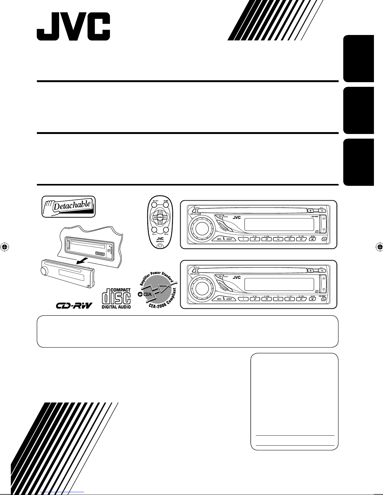
CD RECEIVER KD-G120R/KD-G120
ENGLISH
RECEPTOR CON CD KD-G120R/KD-G120
RECEPTEUR CD KD-G120R/KD-G120
KD-G120R
KD-G120
ESPAÑOL
FRANÇAIS
For canceling the display demonstration, see page 6.
Para cancelar la demostración en pantalla, consulte la página 6.
Pour annuler la démonstration des affichages, référez-vous à la page 6.
For installation and connections, refer to the separate manual.
Para la instalación y las conexiones, refiérase al manual separado.
Pour l’installation et les raccordements, se référer au manuel séparé.
INSTRUCTIONS
MANUAL DE INSTRUCCIONES
MANUEL D’INSTRUCTIONS
For customer Use:
Enter below the Model
No. and Serial No. which
are located on the top or
bottom of the cabinet.
Retain this information
for future reference.
Model No.
Serial No.
GET0330-001A
[J]
Page 2
Thank you for purchasing a JVC product.
Please read all instructions carefully
before operation, to ensure your complete
understanding and to obtain the best possible
performance from the unit.
ENGLISH
INFORMATION (For U.S.A.)
This equipment has been tested and found
to comply with the limits for a Class B digital
device, pursuant to Part 15 of the FCC
Rules. These limits are designed to provide
reasonable protection against harmful
interference in a residential installation.
This equipment generates, uses, and can
radiate radio frequency energy and, if not
installed and used in accordance with the
instructions, may cause harmful interference
to radio communications. However, there
is no guarantee that interference will not
occur in a particular installation. If this
equipment does cause harmful interference
to radio or television reception, which can
be determined by turning the equipment
off and on, the user is encouraged to try to
correct the interference by one or more of
the following measures:
– Reorient or relocate the receiving antenna.
– Increase the separation between the
equipment and receiver.
– Connect the equipment into an outlet on
a circuit different from that to which the
receiver is connected.
– Consult the dealer or an experienced radio/
TV technician for help.
Warning:
If you need to operate the unit while driving,
be sure to look ahead carefully or you may be
involved in a traffic accident.
How to reset your unit
• Your preset adjustments will also be erased.
• If a disc is loaded, it will eject. Be careful not to
drop the disc.
How to forcibly eject a disc
• If this does not work, reset your unit.
• Be careful not to drop the disc when it ejects.
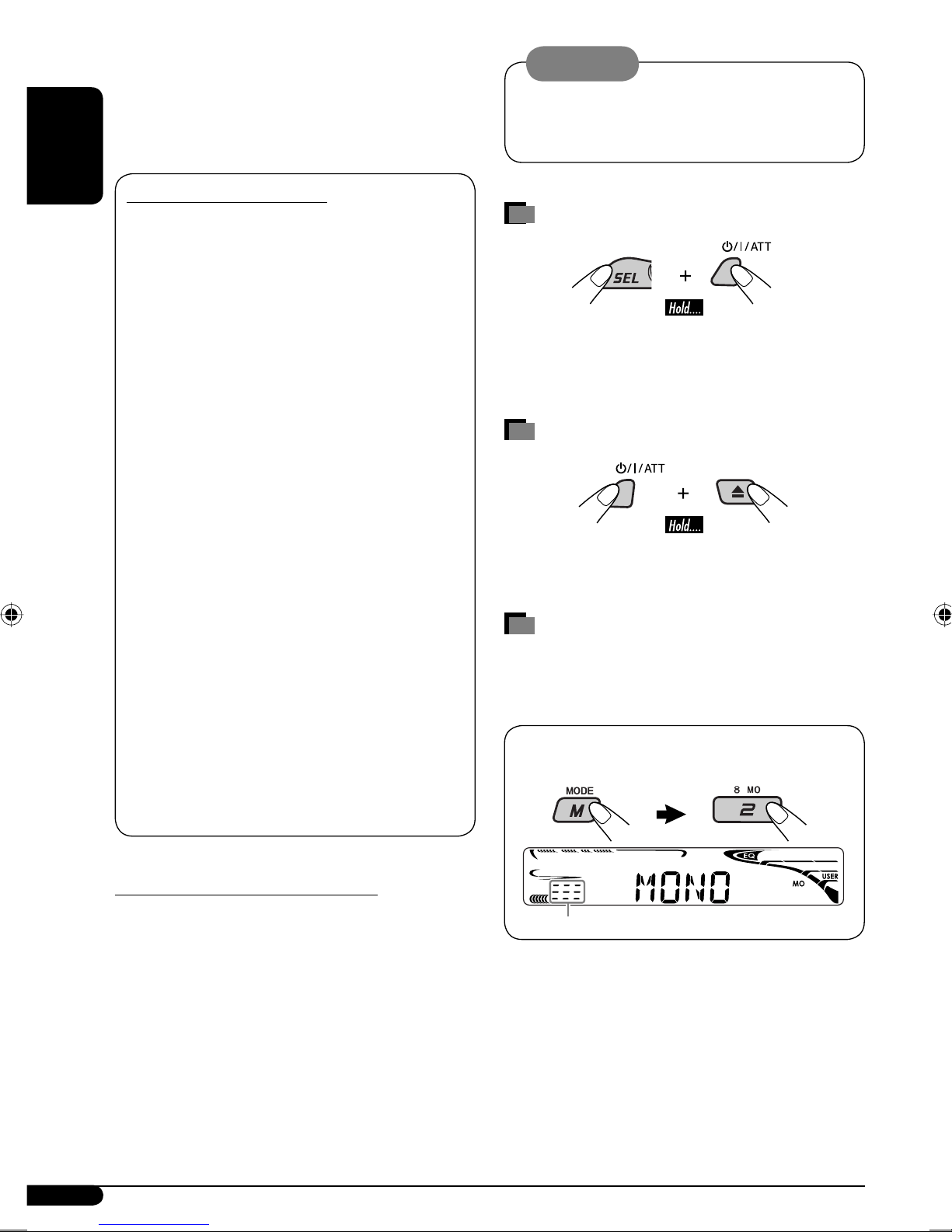
How to use the M MODE button
If you press M MODE, the unit goes into
functions mode, then the number buttons work
as different function buttons.
Ex.: When number button 2 works as
MO (monaural) button.
IMPORTANT FOR LASER PRODUCTS
1. CLASS 1 LASER PRODUCT
2. CAUTION: Do not open the top cover.
There are no user serviceable parts inside
the unit; leave all servicing to qualified
service personnel.
3. CAUTION: Visible and invisible laser
radiation when open and interlock failed or
defeated. Avoid direct exposure to beam.
2
Time countdown indicator
To use these buttons for their original
functions again after pressing M MODE, wait
for 5 seconds without pressing any of these
buttons until the functions mode is cleared or
press M MODE again.
Page 3
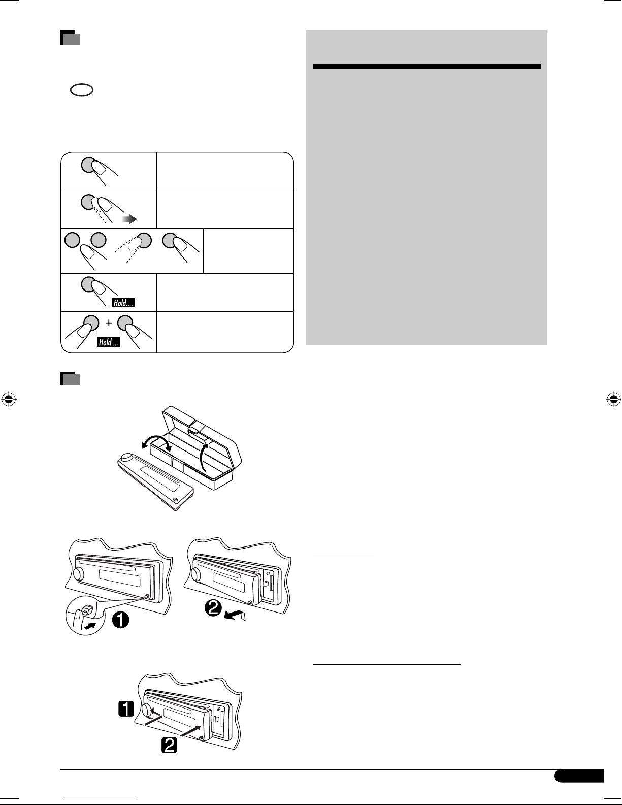
How to read this manual
• Button operations are mainly explained with
the illustrations in the table below.
•
• Some related tips and notes are explained in
is used to indicate an indicator is
displayed for the corresponding operation.
“More about this unit” (see pages 11 and 12).
CONTENTS
Control panel — KD-G120R and KD-G120 ....... 4
Remote controller —
Getting started ................................. 6
Basic operations .................................................... 6
RM-RK50 .............. 5
ENGLISH
Press briefly.
Press repeatedly.
Press either
one.
Press and hold until your
desired response begins.
Press and hold both
buttons at the same time.
How to detach/attach the control
panel
Detaching...
Radio operations .............................. 7
Disc operations ................................. 8
Playing a disc in the unit ....................................... 8
Sound adjustments ........................... 9
General settings — PSM ................... 9
Maintenance .................................... 10
More about this unit ......................... 11
Troubleshooting ............................... 12
Specifications ................................... 13
Caution on volume setting:
Discs produce very little noise compared
with other sources. Lower the volume
before playing a disc to avoid damaging
the speakers by the sudden increase of the
output level.
Attaching...
For safety...
• Do not raise the volume level too much, as
this will block outside sounds, making driving
dangerous.
• Stop the car before performing any
complicated operations.
Temperature inside the car...
If you have parked the car for a long time in hot
or cold weather, wait until the temperature in
the car becomes normal before operating the
unit.
3
Page 4
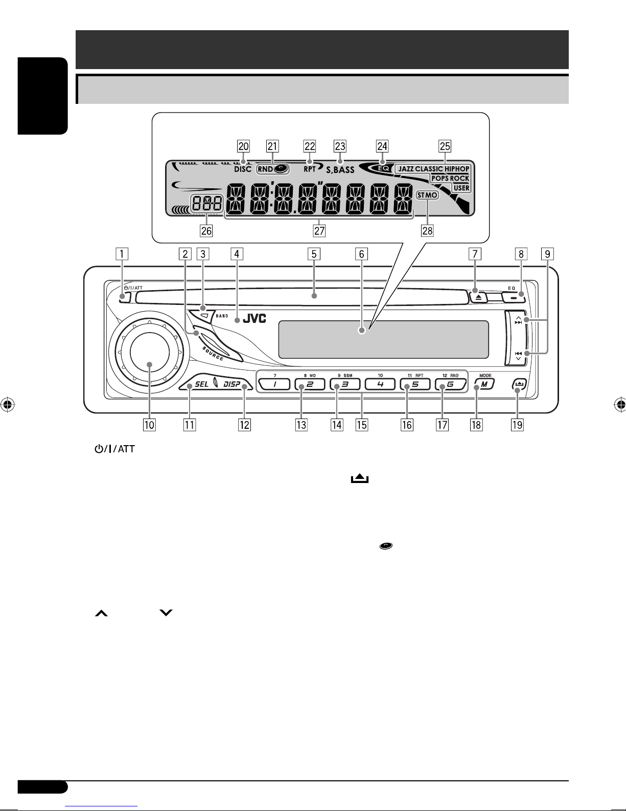
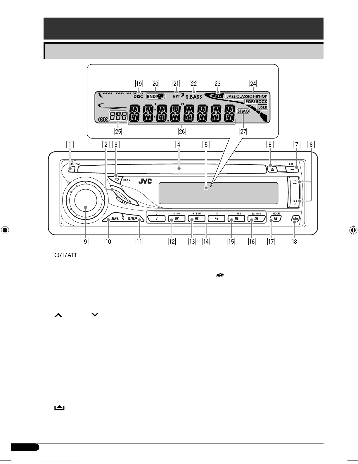
Control panel — KD-G120R and KD-G120
Parts identification
ENGLISH
Display window
1 (standby/on/attenuator) button
2 SOURCE button
3 BAND button
4 Remote sensor—Only for KD-G120R
• DO NOT expose the remote sensor to
strong light (direct sunlight or artificial
lighting).
5 Loading slot
6 Display window
7 0 (eject) button
8 EQ (equalizer) button
9
p Control dial
q SEL (select) button
w DISP (display) button
e MO (monaural) button
r SSM (Strong-station Sequential Memory)
t Number buttons
y RPT (repeat) button
¢/4 buttons
button
u RND (random) button
i M MODE button
o
(control panel release) button
Display window
; DISC indicator
a RND
s RPT (repeat) indicator
d S. BASS (super bass) indicator
f EQ (equalizer) indicator
g Sound mode (C-EQ: custom equalizer)
indicators—JAZZ, CLASSIC, HIP HOP,
POPS, ROCK, USER
h Source display
Volume level indicator
Time countdown indicator
j Main display
k Tuner reception indicators— ST (stereo),
MO (monaural)
(disc random) indicator
4
Page 5
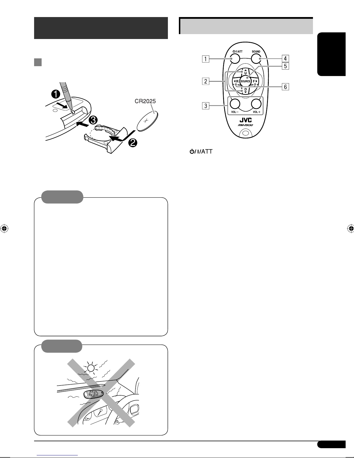
Remote controller — RM-RK50
• RM-RK50 is supplied only for KD-G120R.
Installing the lithium coin battery
(CR2025)
Aim the remote controller directly at the
remote sensor on the unit. Make sure there is
no obstacle in between.
Warning:
• Do not install any battery other than
CR2025 or its equivalent; otherwise, it may
explode.
• Store the battery in a place where children
cannot reach to avoid risk of accident.
• To prevent the battery from over-heating,
cracking, or starting a fire:
– Do not recharge, short, disassemble,
heat the battery, or dispose of it in a fire.
– Do not leave the battery with other
metallic materials.
– Do not poke the battery with tweezers or
similar tools.
– Wrap the battery with tape and insulate
when throwing away or saving it.
Main elements and features
ENGLISH
1 (standby/on/attenuator) button
• Turns the power on if pressed briefly or
attenuates the sound when power is on.
• Turns the power off if pressed and held.
2 5 U (up) / D (down) ∞ buttons
• Changes the FM/AM bands with 5 U
only.
• Changes the preset stations with D ∞
only.
3 VOL – / VOL + buttons
• Adjusts the volume level.
4 SOUND button
• Selects the sound mode (C-EQ: custom
equalizer).
5 SOURCE button
• Selects the source.
6 2 R (reverse) / F (forward) 3 buttons
• Searches for stations if pressed briefly.
• Fast-forwards or reverses the track if
pressed and held.
• Changes the tracks of the disc if pressed
briefly.
Caution:
5
Page 6
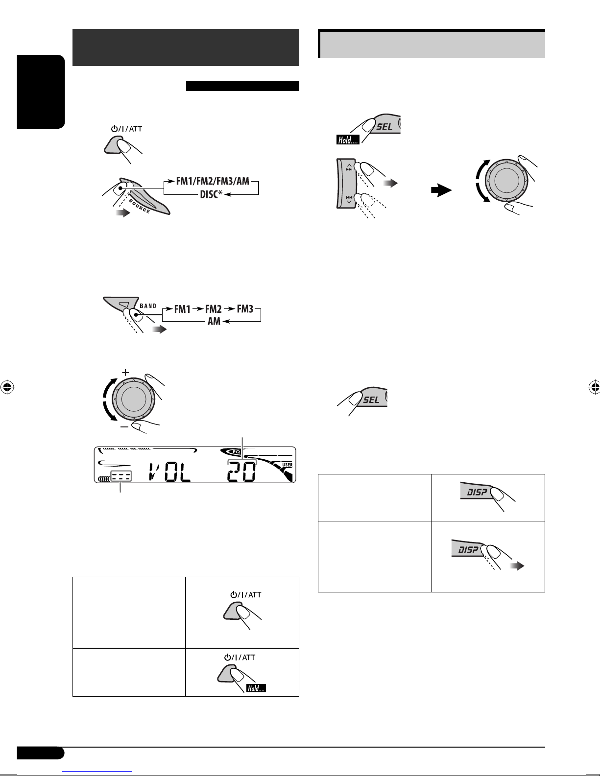
Getting started
Basic operations
Basic settings
• See also “General settings — PSM” on pages 9
and 10.
~ Turn on the power.
ENGLISH
Ÿ
* You cannot select “DISC” as the
playback source if there is no disc in the
loading slot.
! For FM/AM tuner
⁄ Adjust the volume.
1
2
1 Canceling the display
demonstrations
Select “DEMO,” then “DEMO OFF.”
2 Setting the clock
Select “CLOCK H” (hour), then adjust
the hour.
Select “CLOCK M” (minute), then
adjust the minute.
3 Finish the procedure.
.
Volume level indicator
Volume level appears
To check the current clock time while...
The power is turned
off
@ Adjust the sound as you want. (See
page 9.)
To drop the volume
in a moment (ATT)
To restore the sound,
press it again.
To turn off the
power
Listening to the
radio/a disc
Frequency/Elapsed
playing time Ô Clock
6
Page 7
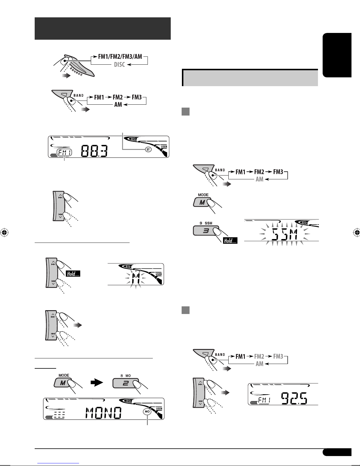
Radio operations
~
Ÿ
Reception improves, but stereo effect will be
lost.
To restore the stereo effect, repeat the same
procedure “MONO OFF” appears and the MO
indicator goes off.
ENGLISH
Storing stations in memory
You can preset six stations for each band.
Lights up when receiving an FM stereo
broadcast with sufficient signal strength.
Selected band appears.
! Start searching for a station.
When a station is received,
searching stops.
To stop searching, press the
same button again.
To tune in to a station manually
In step ! above...
1
2 Select the desired station frequencies.
FM station automatic presetting —
SSM (Strong-station Sequential
Memory)
1 Select the FM band (FM1 – FM3) you
want to store into.
2
3
“SSM” flashes, then disappears when
automatic presetting is over.
Local FM stations with the strongest signals are
searched and stored automatically in the FM
band.
Manual presetting
When an FM stereo broadcast is hard to
receive
Lights up when monaural mode is activated.
Ex.: Storing FM station of 92.5 MHz into preset
number 4 of the FM1 band.
1
2
To be continued...
7
Page 8
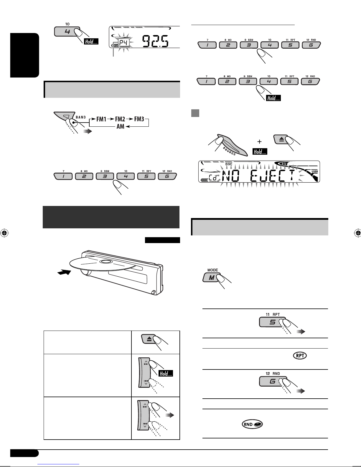
3
ENGLISH
Listening to a preset station
To locate a particular track directly
To select a number from 01 – 06:
Preset number flashes for a while.
To select a number from 07 – 12:
1
2 Select the preset station (1 – 6) you
want.
Disc operations
Playing a disc in the unit
Prohibiting disc ejection
You can lock a disc in the loading slot.
To cancel the prohibition, repeat the same
procedure.
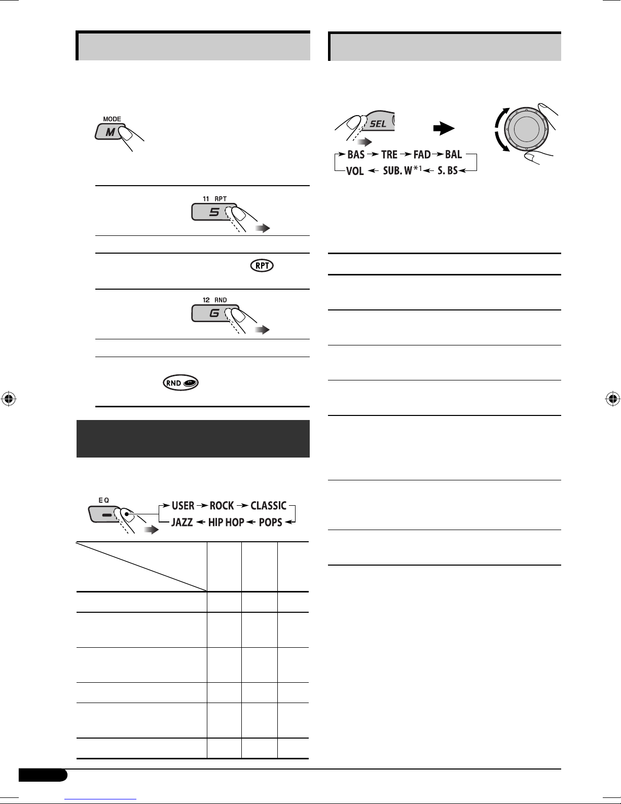
Selecting the playback modes
You can use only one of the following playback
modes at a time.
1
All tracks will be played repeatedly until you
change the source or eject the disc.
To stop play and eject the
disc
To fast-forward or reverse
the track
To go to the next or
previous tracks
8
2 Select your desired playback mode.
7 Repeat play
Mode Plays repeatedly
TRK RPT : The current track.
RPT OFF : Cancels.
7 Random play
Mode Plays at random
DISC RND : All tracks of the current disc.
RND OFF : Cancels.
Page 9
Sound adjustments
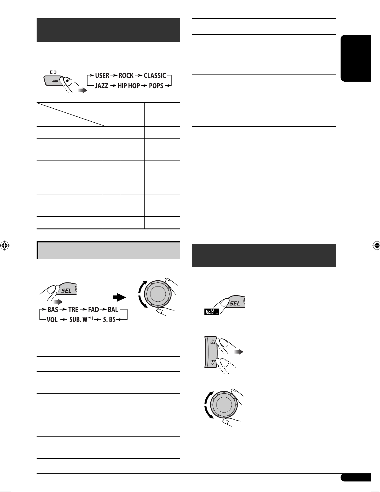
You can select a preset sound mode suitable to
the music genre (C-EQ: custom equalizer).
Preset values
Indication (For)
USER (Flat sound)
ROCK
(Rock or disco music)
CLASSIC
(Classical music)
POPS (Light music)
HIP HOP
(Funk or rap music)
JAZZ (Jazz music)
BAS TRE S.BS
(bass) (treble)
00 00 OFF
+03 +01 ON
+01 –02 OFF
+04 +01 OFF
+02 00 ON
+02 +03 OFF
(super bass)
Indication, [Range]
S.BS*2 (super bass), [S.BS ON or S.BS OFF]
[01 to 05]
Maintain the richness and fullness of the bass
sound regardless of how low you set the volume.
SUB. W
Adjust the subwoofer output level when a
subwoofer is connected.
VOL (volume), [00 to 30 or 50*
Adjust the volume.
2
*
When you adjust the bass, treble, or
3
*
If you are using a two-speaker system, set the
4
*
This adjustment cannot affect the subwoofer
5
*
Range adjustment for super bass is adjustable
6
*
Depending on the amplifier gain control
(subwoofer), [00 to 08]
super bass the adjustment you have made is
stored for the currently selected sound mode
(C-EQ) including “USER.”
fader level to “00.”
output.
only when it is set to “S.BS ON.”
setting. (See page 10 for details.)
5
*
6
]
ENGLISH
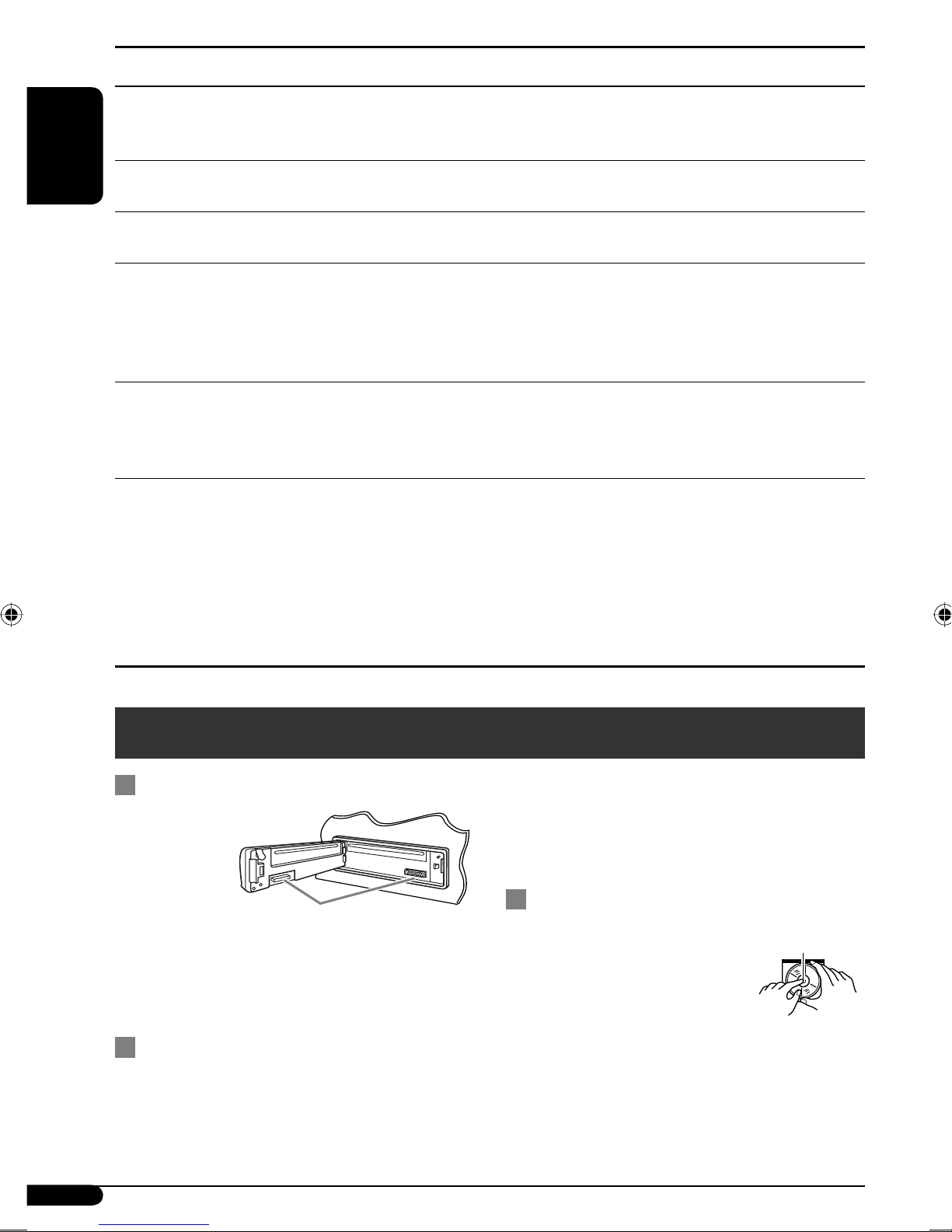
Adjusting the sound
You can adjust the sound characteristics to your
preference.
*1 Displayed only when “L/O MODE” is set to
“WOOFER” (see page 10).
Indication, [Range]
BAS*2 (bass), [–06 to +06]
Adjust the bass.
2
TRE*
(treble), [–06 to +06]
Adjust the treble.
FAD*3 (fader), [R06 to F06]
Adjust the front and rear speaker balance.
4
BAL*
Adjust the left and right speaker balance.
(balance), [L06 to R06]
General settings — PSM
You can change PSM (Preferred Setting Mode)
items listed in the table on page 10.
1
2 Select a PSM item.
3 Adjust the PSM item selected.
4 Repeat steps 2 and 3 to adjust other
PSM items if necessary. Then press
SEL to finish the procedure.
To be continued...
9
Page 10
Indications Selectable settings, [reference page]
DEMO
Display
demonstration
CLOCK H
ENGLISH
Hour adjustment
CLOCK M
Minute adjustment
L/O MODE
Line output mode
AMP GAIN
Amplifier gain
control
AREA
Tuner channel
interval
DEMO ON : [Initial]; Display demonstration will be activated automatically
if no operation is done for about 20 seconds, [6].
DEMO OFF : Cancels.
1 – 12, [6]
[Initial: 1 (1:00)]
00 – 59, [6]
[Initial: 00 (1:00)]
When connecting an amplifier or a subwoofer, set this correctly.
REAR : [Initial]; Select if the REAR LINE OUT terminals are used for
connecting the speakers through an external amplifier.
WOOFER : Select if the REAR LINE OUT terminals are used for
connecting a subwoofer.
You can change the maximum volume level of this unit.
LOW PWR : VOL 00 – VOL 30 (Select this if the maximum power of the
speaker is less than 45 W to avoid damaging the speaker.)
HIGH PWR : [Initial]; VOL 00 – VOL 50
AREA US : [Initial]; Select this when using the unit in North or South
America, except Middle South America. (FM: 200 kHz; AM:
10 kHz)
AREA EU : Select this when using the unit in any other area than North,
Middle South and South America. (FM: 50 kHz—manual
tuning, 100 kHz—auto search; AM: 9 kHz)
AREA SA : Select this when using the unit in Middle South America.
(FM: 100 kHz; AM: 10 kHz)
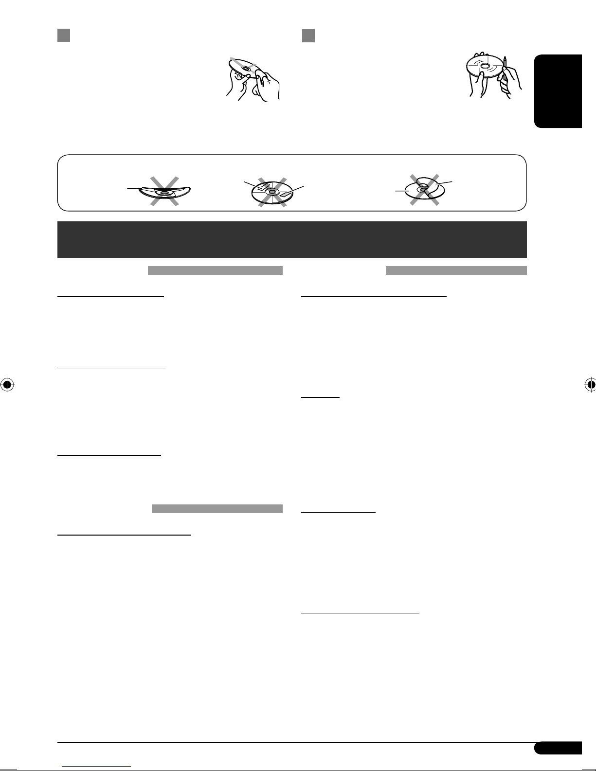
Maintenance
How to clean the connectors
Frequent
detachment
will deteriorate
the connectors.
To minimize
this possibility,
periodically wipe the connectors with a cotton
swab or cloth moistened with alcohol, being
careful not to damage the connectors.
Moisture condensation
Moisture may condense on the lens inside the
CD player in the following cases:
• After starting the heater in the car.
• If it becomes very humid inside the car.
Connector
Should this occur, the CD player may
malfunction.In this case, eject the disc and leave
the unit turned on for a few hours until the
moisture evaporates.
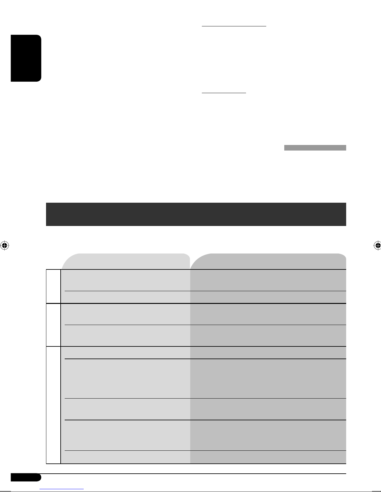
How to handle discs
When removing a disc from
its case, press down the center
holder of the case and lift the
disc out, holding it by the edges.
• Always hold the disc by the
edges. Do not touch its recording surface.
When storing a disc into its case, gently insert
the disc around the center holder (with the
printed surface facing up).
• Make sure to store discs into the cases after
use.
Center holder
10
Page 11
To keep discs clean
To play new discs
A dirty disc may not play correctly.
If a disc does become dirty, wipe it
with a soft cloth in a straight line
from center to edge.
• Do not use any solvent (for
example, conventional record cleaner, spray,
thinner, benzine, etc.) to clean discs.
Do not use the following discs:
Sticker
Warped disc
More about this unit
Basic operations
Turning on the power
• By pressing SOURCE on the unit, you can
also turn on the power. If the source is ready,
playback also starts.
Turning off the power
• If you turn off the power while listening to a
disc, disc play will start from where playback
has been stopped previously, next time you
turn on the power.
Selecting the sources
• When no disc is loaded in the unit, “DISC”
cannot be selected.
New discs may have some rough
spots around the inner and outer
edges. If such a disc is used, this
unit may reject the disc.
To remove these rough spots, rub the edges
with a pencil or ball-point pen, etc.
Sticker residue
Disc
Stick-on label
Disc operations
Caution for DualDisc playback
• The Non-DVD side of a “DualDisc” does
not comply with the “Compact Disc Digital
Audio” standard. Therefore, the use of NonDVD side of a DualDisc on this product may
not be recommended.
General
• This unit has been designed to reproduce
CDs, and CD-Rs (Recordable)/CD-RWs
(Rewritable) in audio CD (CD-DA) format.
• When a disc has been loaded, selecting
“DISC” for the playback source starts disc
play.
ENGLISH
Tuner operations
Storing stations in memory
• During SSM search...
– All previously stored stations are erased and
stations are stored newly.
–
Received stations are preset in No. 1 (lowest
frequency) to No. 6 (highest frequency).
– When SSM is over, the station stored in
No. 1 will be automatically tuned in.
• When storing a station manually, a previously
preset station is erased when a new station is
stored in the same preset number.
Inserting a disc
• When a disc is inserted upside down, the disc
automatically ejects.
• Do not insert 8 cm discs (single CD) and
unusual shape discs (heart, flower, etc.) into
the loading slot.
Playing a CD-R or CD-RW
• Use only “finalized” CD-Rs or CD-RWs.
• This unit can play back multi-session discs;
however, unclosed sessions will be skipped
while playing.
• Some CD-Rs or CD-RWs may not play
back on this unit because of their disc
characteristics, and for the following causes:
To be continued...
11
Page 12
– Discs are dirty or scratched.
– Moisture condensation occurs on the lens
inside the unit.
– The pickup lens inside the unit is dirty.
– CD-R/CD-RW on which the files are
written with “Packet Write” method.
ENGLISH
– There are improper recording conditions
(missing data, etc.) or media conditions
(stain, scratch, warp, etc.).
• CD-RWs may require a longer readout time
since the reflectance of CD-RWs is lower than
that of regular CDs.
• Do not use the following CD-Rs or CD-RWs:
– Discs with stickers, labels, or protective seal
stuck to the surface.
– Discs on which labels can be directly
printed by an ink jet printer.
Using these discs under high temperatures
or high humidity may cause malfunctions or
damages to the unit.
Changing the source
• If you change the source, playback also stops
(without ejecting the disc).
Next time you select “DISC” for the playback
source, disc play starts from where it has been
stopped previously.
Ejecting a disc
• If the ejected disc is not removed within
15 seconds, the disc is automatically inserted
again into the loading slot to protect it from
dust. (Disc will not play this time.)
General settings—PSM
• If you change the “AMP GAIN” setting from
“HIGH PWR” to “LOW PWR” while the
volume level is set higher than “VOL 30,” the
unit automatically changes the volume level to
“VOL 30.”
Troubleshooting
What appears to be trouble is not always serious. Check the following points before calling a service
center.
Symptoms Remedies/Causes
• Sound cannot be heard from the
speakers.
General
• This unit does not work at all. Reset the unit (see page 2).
• SSM automatic presetting does not
work.
• Static noise while listening to the
FM/AM
radio.
• Disc automatically ejects. Insert the disc correctly.
• CD-R/CD-RW cannot be played
back.
• Tracks on the CD-R/CD-RW cannot
be skipped.
• Adjust the volume to the optimum level.
• Check the cords and connections.
Store stations manually.
Connect the antenna firmly.
• Insert a finalized CD-R/CD-RW.
•
Finalize the CD-R/CD-RW with the component
which you used for recording.
• Disc can be neither played back nor
ejected.
Disc playback
• Disc sound is sometimes interrupted. • Stop playback while driving on rough roads.
• “NO DISC” appears on the display. Insert a playable disc into the loading slot.
12
• Unlock the disc (see page 8).
• Eject the disc forcibly (see page 2).
• Change the disc.
• Check the cords and connections.
Page 13
Specifications
AUDIO AMPLIFIER SECTION
Power Output:
17 W RMS × 4 Channels at 4 Ω
and ≤ 1% THD+N
Signal to Noise Ratio:
80 dBA (reference: 1 W into 4 Ω)
Load Impedance: 4 Ω (4 Ω to 8 Ω allowance)
Tone Control Range:
Bass: ±10 dB at 100 Hz
Treble: ±10 dB at 10 kHz
Frequency Response: 40 Hz to 20 000 Hz
Line-Out Level/Impedance:
2.0 V/20 kΩ load (full scale)
Output Impedance: 1 kΩ
Subwoofer-Out Level/Impedance:
2.0 V/20 kΩ load (full scale)
TUNER SECTION
Frequency Range:
FM: 87.5 MHz to 107.9 MHz
(with channel interval set to 100 kHz
or 200 kHz)
87.5 MHz to 108.0 MHz
(with channel interval set to 50 kHz)
AM: 530 kHz to 1 710 kHz
(with channel interval set to 10 kHz)
531 kHz to 1 602 kHz
(with channel interval set to 9 kHz)
[FM Tuner]
CD PLAYER SECTION
Type: Compact disc player
Signal Detection System: Non-contact optical
pickup (semiconductor laser)
Number of channels: 2 channels (stereo)
Frequency Response: 5 Hz to 20 000 Hz
Dynamic Range: 96 dB
Signal-to-Noise Ratio: 98 dB
Wow and Flutter: Less than measurable limit
GENERAL
Power Requirement:
Operating Voltage:
Grounding System: Negative ground
Allowable Operating Temperature:
0°C to +40°C (32°F to 104°F)
Dimensions (W × H × D):
Installation Size (approx.):
182 mm × 52 mm × 150 mm
(7-3/16” × 2-1/16” × 5-15/16”)
Panel Size (approx.):
188 mm × 58 mm × 11 mm
(7-7/16” × 2-5/16” × 7/16”)
Mass (approx.):
1.2 kg (2.6 lbs) (excluding accessories)
Design and specifications are subject to change
without notice.
DC 14.4 V (11 V to 16 V allowance)
If a kit is necessary for your car, consult your
telephone directory for the nearest car audio
speciality shop.
ENGLISH
Usable Sensitivity: 11.3 dBf (1.0 μV/75 Ω)
50 dB Quieting Sensitivity:
16.3 dBf (1.8 μV/75 Ω)
Alternate Channel Selectivity (400 kHz): 65 dB
Frequency Response: 40 Hz to 15 000 Hz
Stereo Separation: 35 dB
Capture Ratio: 1.5 dB
[AM Tuner]
Sensitivity: 20 μV
Selectivity: 35 dB
13
Page 14
Having TROUBLE with operation?
Please reset your unit
Refer to page of How to reset your unit
Still having trouble??
USA ONLY
Call 1-800-252-5722
http://www.jvc.com
We can help you!
EN, SP, FR
© 2005 Victor Company of Japan, Limited
1005DTSMDTJEIN
Page 15
KD-G120R/KD-G120
Installation/Connection Manual
Manual de instalación/conexión
Manuel d’installation/raccordement
GET0330-002A
[J]
1005DTSMDTJEIN
EN, SP, FR
ENGLISH
This unit is designed to operate on 12 V DC, NEGATIVE ground
electrical systems. If your vehicle does not have this system, a
voltage inverter is required, which can be purchased at JVC car audio
dealers.
ESPAÑOL
Esta unidad está diseñada para funcionar con 12 V de CC, con
sistemas eléctricos de masa NEGATIVA. Si su vehículo no posee
este sistema, será necesario un inversor de tensión, que puede ser
adquirido en los concesionarios de JVC de equipos de audio para
automóviles.
FRANÇAIS
Cet appareil est conçu pour fonctionner sur des sources de courant
continu de 12 V à masse NEGATIVE. Si votre véhicule n’offre pas ce
type d’alimentation, il vous faut un convertisseur de tension, que vous
pouvez acheter chez un revendeur d’autoradios JVC.
1
© 2005 Victor Company of Japan, Limited
J
Handles
Manijas
Poignées
F
Washer (ø5)
Arandela (ø5)
Rondelle (ø5)
G
Lock nut (M5)
Tuerca de seguridad (M5)
Ecrou d’arrêt (M5)
H
Mounting bolt—M5 × 20 mm (M5 × 13/16")
Perno de montaje—M5 × 20 mm (M5 × 13/16 pulgada)
Boulon de montage—M5 × 20 mm (M5 × 13/16 pouces)
I
Rubber cushion
Cojín de goma
Amortisseur en caoutchouc
A / B
Hard case/Control panel
Estuche duro/Panel de control
Etui de transport/Panneau de commande
C
Sleeve
Cubierta
Manchon
D
Trim plate
Placa de guarnición
Plaque d’assemblage
E
Power cord
Cordón de alimentación
Cordon d’alimentation
Parts list for installation and connection
The following parts are provided for this unit. After checking them,
please set them correctly.
Lista de piezas para instalación y conexión
Con esta unidad se suministran las siguientes piezas. Después de
inspeccionarlas, colóquelas correctamente.
Liste des pièces pour l’installation et
raccordement
Les pièces suivantes sont fournies avec cet appareil. Après vérification,
veuillez les placer correctement.
Heat sink
Sumidero térmico
Dissipateur de chaleur
WARNINGS
To prevent short circuits, we recommend that you disconnect the
battery’s negative terminal and make all electrical connections before
installing the unit.
• Be sure to ground this unit to the car’s chassis again after
installation.
Notes:
• Replace the fuse with one of the specified rating. If the fuse blows
frequently, consult your JVC car audio dealer.
• It is recommended to connect to the speakers with maximum
power of more than 45 W (both at the rear and at the front, with
an impedance of
4 Ω to 8 Ω). If the maximum power is less than
45 W, change “AMP GAIN” setting to prevent the speakers from
being damaged (see page 10 of the INSTRUCTIONS).
• To prevent short-circuit, cover the terminals of the UNUSED leads
with insulating tape.
• The heat sink becomes very hot after use. Be careful not to touch it
when removing this unit.
ADVERTENCIAS
Para evitar cortocircuitos, recomendamos que desconecte el terminal
negativo de la batería y que efectúe todas las conexiones eléctricas
antes de instalar la unidad.
• Asegúrese de vol ver a conectar a masa esta unid ad al chasis
del automóvil desp ués de la instalación.
Notas:
• Reemplace el fusible por uno con la corriente especificada. Si el
fusible se quemase frecuentemente consulte con su concesionario
de JVC de equipos de audio para automóviles.
• Se recomienda conectar los altavoces con una potencia máxima de
más de 45 W (tanto atrás como adelante, con una impedancia de
4 Ω a 8 Ω). Si la potencia máxima es de menos de 45 W, cambie
“AMP GAIN” para evitar daños en los altavoces (consulte la página 10
del MANUAL DE INSTRUCCIONES).
• Para evitar cortocircuitos, cubra los cables NO UTILIZADOS con cinta
aislante.
• El sumidero térmico estará muy caliente después del uso. Asegúrese
de no tocarlo al desmontar esta unidad.
AVERTISSEMENTS
Pour éviter tout court-circuit, nous vous recommandons de débrancher
la borne négative de la batterie et d’effectuer tous les raccordements
électriques avant d’installer l’appareil.
• Assurez-vous de raccor der de nouveau la mise à la masse de
cet appareil au ch âssis de la voiture après l’inst allation.
Remarques:
• Remplacer le fusible par un de la valeur précisée. Si le fusible saute
souvent, consulter votre revendeur d’autoradios JVC.
• Il est recommandé de connecter des enceintes avec une puissance de
plus de 45 W (les enceintes arrière et les enceintes avant, avec une
impédance comprise entre
4 Ω et 8 Ω). Si la puissance maximum est
inférieure à 45 W, changez “AMP GAIN” pour éviter d’endommager
vos enceintes (voir page 10 du MANUEL D’INSTRUCTIONS).
• Pour éviter les court-circuits, couvrir les bornes des fils qui ne sont
PAS UTILISÉS avec de la bande isolante.
• Le dissipateur de chaleur devient très chaud après usage. Faire
attention de ne pas le toucher en retirant cet appareil.
PRECAUTIONS on power supply and speaker
connections:
• DO NOT connect the speaker leads of the power cord to the
car battery; otherwise, the unit will be seriously damaged.
• BEFORE connecting the speaker leads of the power cord to the
speakers, check the speaker wiring in your car.
PRECAUCIONES sobre las conexiones de la
fuente de alimentación y de los altavoces:
• NO conecte los co nductores de altavoz del cabl e de
alimentación a l a batería de automóvil, pues podr ían
producirse graves da ños en la unidad.
• ANTES de conectar a los altavoces los conductores de altavoz del
cable de alimentación, verifique el conexionado de altavoz de su
automóvil.
PRECAUTIONS sur l’alimentation et la
connexion des enceintes:
• NE CONNECTEZ PAS les fils d’enceintes du cordon
d’alimentation à la b atterie; sinon, l’appareil s erait
sérieusement endommagé.
• AVANT de connecter les fils d’enceintes du cordon d’alimentation
aux enceintes, vérifiez le câblage des enceintes de votre voiture.
K
Remote controller
Control remoto
Télécommade
L
Battery
Pila
Pile
Only for KD-G120R / Sólo para KD-G120R / Seulement pour le KD-G120R
Page 16
When installing the unit without using the sleeve / Instalación de la unidad sin utilizar
la cubierta / Lors de l’installation de l’appareil scans utiliser de manchon
In a Toyota car for example, first remove the car radio and install the unit in its place.
En un automóvil Toyota, por ejemplo, en primer lugar desmonte el autorradio e instale la unidad en su lugar.
Dans une voiture Toyota, par exemple, retirez d’abord l’autoradio et installez l’appareil à sa place.
When using the optional stay / Cuando emplea un
soporte opcional / Lors de l’utilisation du hauban en
option
Note : When installing the unit on the mounting bracket, make sure to use the 8 mm (3/8") -long screws. If longer
screws are used, they could damage the unit.
Nota : Cuando instala la unidad en la ménsula de montaje, asegúrese de utilizar los tornillos de 8 mm (3/8 pulgada) de
longitud. Si se utilizan tornillos más largos, éstos pueden dañar la unidad.
Remarque : Lors de l’installation de l’appareil sur le support de montage, s’assurer d’utiliser des vis d’une longueur de 8 mm
(3/8 pouces). Si des vis plus longues sont utilisées, elles peuvent endommager l’appareil.
* Not supplied for this unit.
* No suministrado con esta unidad.
* Non fourni avec cet appareil.
Flat type screws—M5 × 8 mm (M5 × 3/8")*
Tornillos tipo plano—M5 × 8 mm (M5 × 3/8 pulgada)*
Vis à tête plate—M5 × 8 mm (M5 × 3/8 pouces)*
Pocket
Compartimiento
Poche
Flat type screws—M5 × 8 mm (M5 × 3/8")*
Tornillos tipo plano—M5 × 8 mm(M5 × 3/8 pulgada)*
Vis à tête plate—M5 × 8 mm (M5 × 3/8 pouces)*
Screw (option)
Tornillo (opción)
Vis (en option)
Stay (option)
Soporte (opción)
Hauban (en option)
Fire wall
Tabique a prueba de incendios
Cloison
Dashboard
Tablero de
instrumentos
Tableau de bord
Install the unit at an angle of less
than 30˚.
Instale la unidad a un ángulo de
menos de 30˚.
Installez l’appareil avec un angle de
moins de 30˚.
2
Bracket*
Ménsula*
Support *
Removing the unit
Before removing the unit, release the rear section.
Extracción de la unidad
Antes de extraer la unidad, libere la sección trasera.
Insert the two handles, then pull them as
illustrated so that the unit can be removed.
Inserte las dos manijas y, a continuación,
extráigalas de la manera indicada en la ilustración
para poder desmontar la unidad.
Insérez les deux poignées, puis tirez de la façon
illustrée de façon à retirer l’appareil.
Retrait de l’appareil
Avant de retirer l’appareil, libérer la section arrière.
Do the required electrical connections.
Realice las conexiones eléctricas requeridas.
Réalisez les connexions électriques.
*
1
When you stand the unit, be careful not to damage the fuse on the rear.
*
1
Al poner la unidad vertical, tenga cuidado de no dañar el fusible provisto en la parte posterior.
*
1
Lorsque vous mettez l’appareil à la verticale, faire attention de ne pas endommager le fusible situé sur
l’arrière.
Bend the appropriate tabs to hold the
sleeve firmly in place.
Doble las lengüetas apropiadas para
retener firmemente la manga en su lugar.
Tordez les languettes appropriées pour
maintenir le manchon en place.
INSTALLATION
(IN-DASH MOUNTING)
The following illustration shows a typical installation. If you have any
questions or require information regarding installation kits, consult
your JVC car audio dealer or a company supplying kits.
• If you are not sure how to install this unit correctly, have it installed
by a qualified technician.
INSTALACION (MONTAJE EN EL
TABLERO DE INSTRUMENTOS)
La siguiente ilustración muestra una instalación típica. Si tiene alguna
pregunta o necesita información acerca de las herramientas para
instalación, consulte con su concesionario de JVC de equipos de audio
para automóviles o a una compañía que suministra tales herramientas.
• Si usted no está seguro de cómo instalar correctamente la unidad,
hágala instalar por un técnico cualificado.
INSTALLATION (MONTAGE
DANS LE TABLEAU DE BORD)
L’illustration suivante est un exemple d’installation typique. Si
vous avez des questions ou avez besoin d’information sur des kits
d’installation, consulter votre revendeur d’autoradios JVC ou une
compagnie d’approvisionnement.
• Si l’on n’est pas sûr de pouvoir installer correctement cet appareil, le
faire installer par un technicien qualifié.
Bracket*
Ménsula*
Support *
Page 17
3
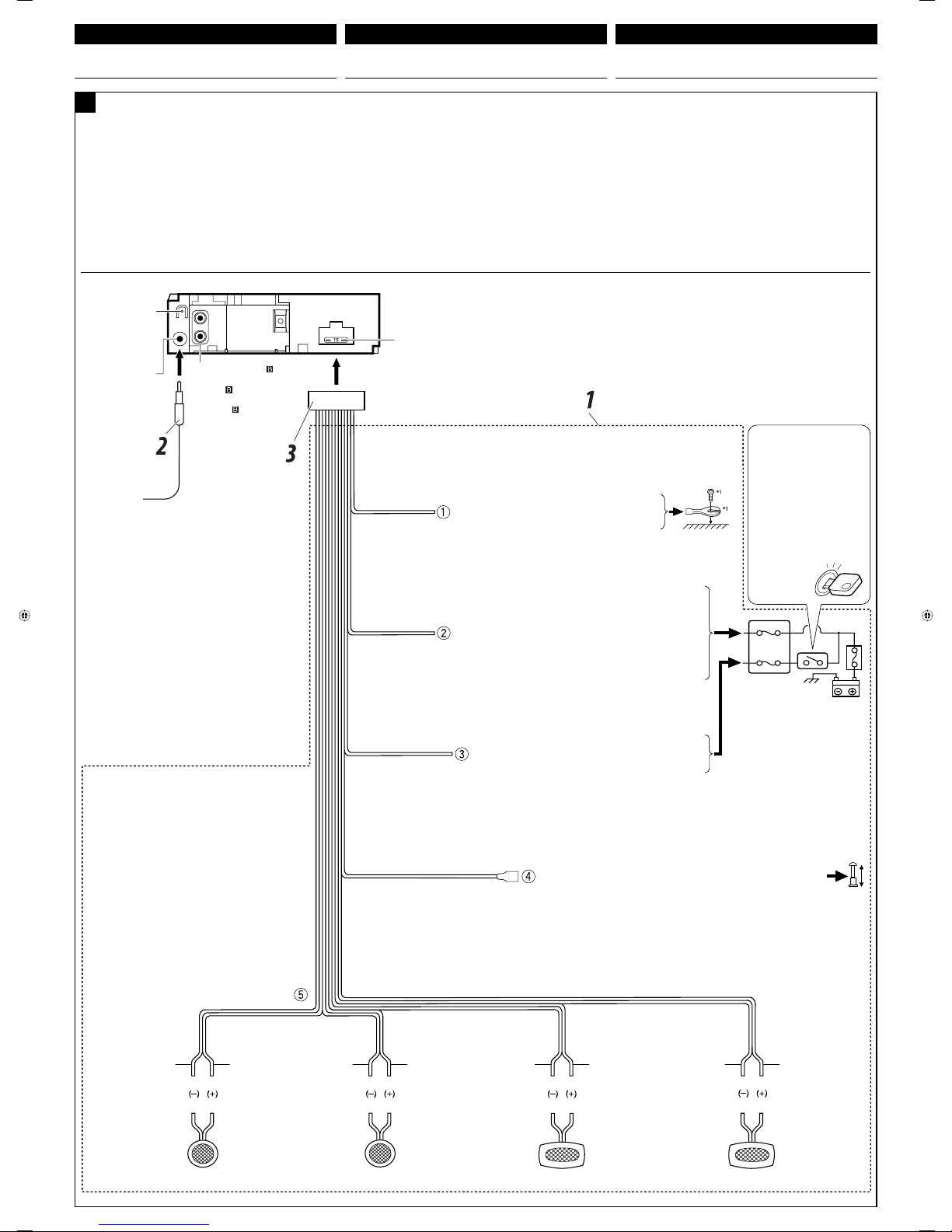
Typical connections / Conexiones tipicas / Raccordements typiques
Before connecting: Check the wiring in the vehicle carefully.
Incorrect connection may cause serious damage to this unit.
The leads of the power cord and those of the connector from the car
body may be different in color.
1 Connect the colored leads of the power cord in the order
specified in the illustration below.
2 Connect the antenna cord.
3 Finally connect the wiring harness to the unit.
Line out (see diagram )
Salida de línea (véase
diagrama )
Sortie de ligne (voir le
diagramme )
Rear ground terminal
Terminal de tierra
posterior
Borne arrière de masse
15 A fuse
Fusible de 15 A
Fusible 15 A
Antenna terminal
Terminal de la antena
Borne de l’antenne
Black
Negro
Noir
Blue with white stripe
Azul con rayas blancas
Bleu avec bande blanche
Red
Rojo
Rouge
Yellow
*
2
Amarillo*
2
Jaune*
2
*
1
Not supplied for this unit
*
1
No suministrado con esta unidad
*
1
Non fourni avec cet appareil
To metallic body or chassis of the car
A un cuerpo metálico o chasis del automóvil
Vers corps métallique ou châssis de la voiture
Ignition switch
Interruptor de encendido
Interrupteur d’allumage
Fuse block
Bloque de fusibles
Porte-fusible
To an accessory terminal in the fuse block
A un terminal accesorio del bloque de fusibles
Vers borne accessoire du porte-fusible
To the remote lead of other equipment or automatic antenna if any
(200 mA max.)
Al conductor remoto de otro equipo o de la antena automática, si hubiere
(máx. 200 mA)
Au fil de télécommande de l’autre appareil ou à l’antenne automatique s’il y en a une
(200 mA max.)
Left speaker (front)
Altavoz izquierdo (delantero)
Enceinte gauche (avant)
Right speaker (front)
Altavoz derecho (delantero)
Enceinte droit (avant)
Left speaker (rear)
Altavoz izquierdo (trasero)
Enceinte gauche (arrière)
Right speaker (rear)
Altavoz derecho (trasero)
Enceinte droit (arrière)
Purple
Púrpura
Violet
Purple with black stripe
Púrpura con rayas negras
Violet avec bande noire
Green
Verde
Vert
Green with black stripe
Verde con rayas negras
Vert avec bande noire
Gray
Gris
Gris
Gray with black stripe
Gris con rayas negras
Gris avec bande noire
White
Blanco
Blanc
White with black stripe
Blanco con rayas negras
Blanc avec bande noire
ENGLISH
Antes de la conexión: Verifique atentamente el conexionado del
vehículo. Una conexión incorrecta podría producir daños graves en la
unidad.
Los cordones del cable de alimentación y los del conector
procedentes de la carrocería del automóvil podrían ser de diferentes
en color.
1 Conecte los conductores de color del cable de alimentación en el
orden especificado en la ilustración de abajo.
2 Conecte el cable de antena.
3 Por último, conecte el cable de alimentación a la unidad.
ESPAÑOL FRANÇAIS
Avant de commencer la connexion: Vérifiez attentivement
le câblage du véhicule. Une connexion incorrecte peut endommager
sérieusement l’appareil.
Le fil du cordon d’alimentation et ceux des connecteurs du châssis de
la voiture peuvent être différents en couleur.
1 Connectez les fils colorés du cordon d’alimentation dans l’ordre
spécifié sur l’illustration ci-dessous.
2 Connectez le cordon d’antenne.
3 Finalement, connectez le faisceau de fils à l’appareil.
To a live terminal in the fuse block connecting to the car battery
(bypassing the ignition switch) (constant 12 V)
A un terminal activo del bloque de fusibles conectado a la batería del
automóvil (desviando el interruptor de encendido)
(12 V constantes)
A une borne sous tension du porte-fusible connectée à la batterie de la
voiture (en dérivant l’interrupteur d’allumage) (12 V constant)
A
*
2
Before checking the operation of this unit prior to installation,
this lead must be connected, otherwise power cannot be
turned on.
*
2
Antes de comprobar el funcionamiento de esta unidad previa
a de la instalación, es necesario conectar este cable, de lo
contrario no se podrá conectar la alimentación.
*
2
Pour vérifier le fonctionnement de cet appareil avant
installation, ce fil doit être raccordé, sinon l’appareil ne peut
pas être mis sous tension.
ELECTRICAL CONNECTIONS CONEXIONES ELECTRICAS RACCORDEMENTS ELECTRIQUES
Page 18
4
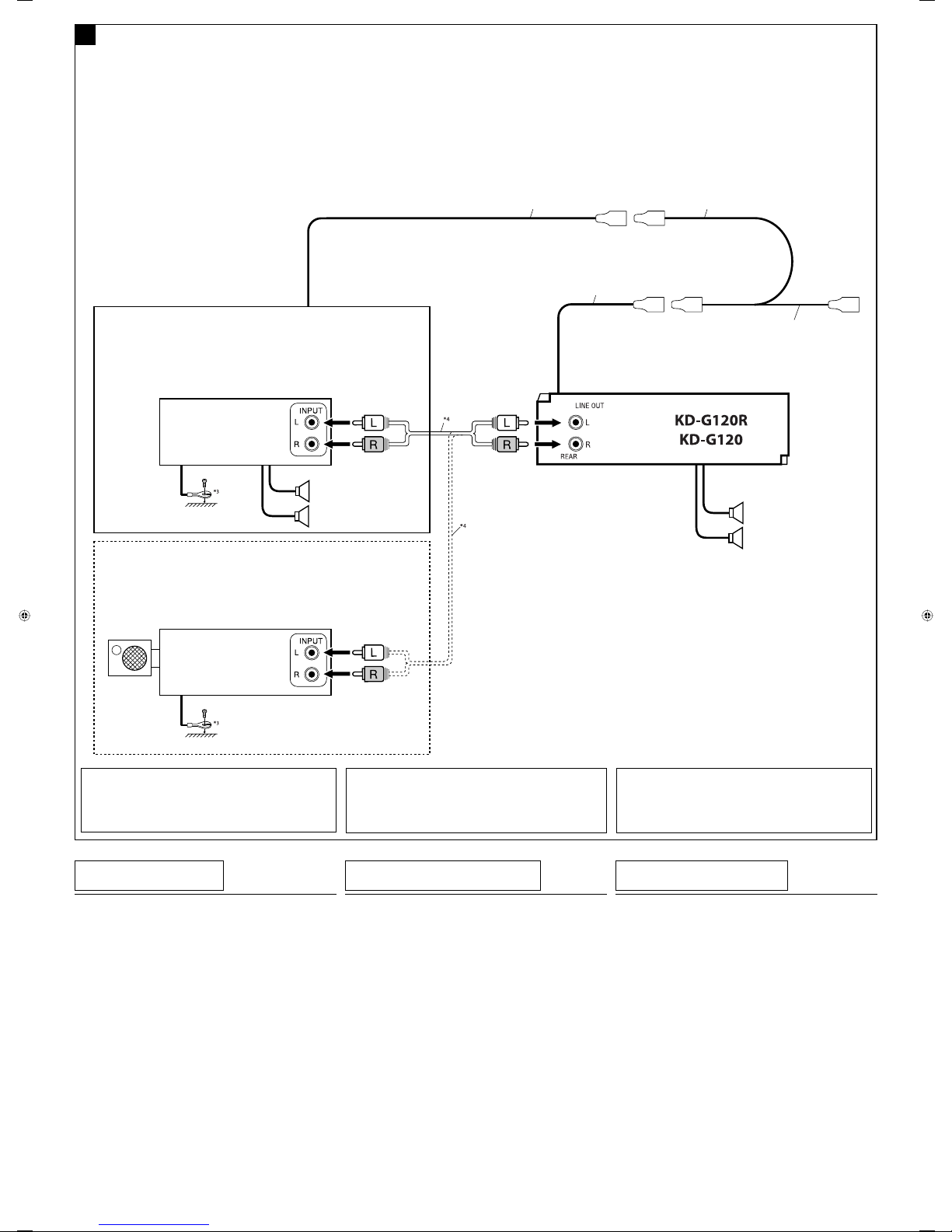
Connecting the external amplifier or subwoofer / Conexión del amplifi cador o subwoofer exterior / Connexion d’un amplificateur extérieur
ou d’un caisson de grave
You can connect an amplifier to upgrade your car stereo system.
• Connect the remote lead (blue with white stripe) to the remote
lead of the other equipment so that it can be controlled through
this unit.
• Disconnect the speakers from this unit, connect them to the
amplifier. Leave the speaker leads of this unit unused.
*
3
Firmly attach the ground wire to the metallic body or to the chassis of
the car—to the place uncoated with paint (if coated with paint, remove
the paint before attaching the wire). Failure to do so may cause damage
to the unit.
*
4
Signal cord (not supplied for this unit)
Usted podrá conectar un amplificador para mejorar el sistema estéreo
de su automóvil.
• Conecte el conductor remoto (azul con rayas blancas) al conductor
remoto del otro equipo para poderlo controlar a través de esta
unidad.
• Desconecte los altavoces de esta unidad y conéctelos al
amplificador. Los cables de los altavoces de esta unidad
quedan sin usar.
Vous pouvez connecter un amplificateur pour améliorer votre système
autoradio.
• Connectez le fil de commande à distance (bleu avec bande blanche)
au fil de commande à distance de l’autre appareil de façon qu’il
puisse être commandé via cet appareil.
• Déconnectez les enceintes de cet appareil et connectez-les
à l’amplificateur. Laissez les fils d’enceintes de cet appareil
inutilisés.
*
3
Fije firmemente el cable de tierra a la carrocería metálica o al chasis—a un
lugar no cubierto con pintura (si está cubierto con pintura, quítela antes de
fijar el cable). De lo contrario, se podrían producir daños en la unidad.
*
4
Cable de señal (no suministrado con esta unidad)
*
3
Attachez solidement le fil de mise à la masse au châssis métallique de la
voiture—à un endroit qui n’est pas recouvert de peinture (s’il est recouvert
de peinture, enlevez d’abord la peinture avant d’attacher le fil). L’appareil
peut être endommagé si cela n’est pas fait correctement.
*
4
Cordon de signal (non fourni avec cet appareil)
B
Rear speakers
Altavoces posteriores
Enceintes arrière
Remote lead
Cable remoto
Fil d’alimentation à distance
Remote lead (Blue with white stripe)
Cable remoto (Azul con rayas blancas)
Fil d’alimentation à distance (Bleu avec bande blanche)
To the remote lead of other equipment or automatic antenna if any
Al conductor remoto de otro equipo o de la antena automática, si hubiere
Au fil de télécommande de l’autre appareil ou à l’antenne automatique s’il y en a une
Y-connector (not supplied for this unit)
Conector en Y (no suministrado con esta unidad)
Connecteur Y (non fourni avec cet appareil)
Front speakers
Altavoces delanteros
Enceintes avant
Subwoofer
Subwoofer
Caisson de grave
Set “L/O MODE” to “REAR” (See page 10 of the INSTRUCTIONS.)
Ajuste “L/O MODE” a “REAR” (Consulte la página 10 del MANUAL DE INSTRUCCIONES.)
Réglez “L/O MODE” sur “REAR” (Voir la page 10 du MANUEL D’INSTRUCTIONS.)
You can also connect a subwoofer to the REAR LINE OUT terminals.
También puede conectar un subwoofer para los terminales REAR LINE OUT.
Vous pouvez aussi connecter un caisson de grave aux prises REAR LINE OUT.
JVC Amplifie r
Amplificador de JVC
JVC Amplificateur
You can connect a power amplifier for rear speakers.
Puede conectar un amplificador de potencia para los altavoces traseros.
Vous pouvez connecter un amplificateur de puissance pour les enceintes arrière.
TROUBLESHOOTING
• The fuse blows.
* Are the red and black leads connected correctly?
• Power cannot be turne d on.
* Is the yellow lead connected?
• No sound from the s peakers.
* Is the speaker output lead short-circuited?
• Sound is distor ted.
* Is the speaker output lead grounded?
* Are the “–” terminals of L and R speakers grounded in common?
• Noise interfere wit h sounds.
* Is the rear ground terminal connected to the car’s chassis using
shorter and thicker cords?
• This unit becomes hot.
* Is the speaker output lead grounded?
* Are the “–” terminals of L and R speakers grounded in common?
• This unit does not work at al l.
* Have you reset your unit?
LOCALIZACION DE AVERIAS
• El fusible se que ma.
* ¿Están los conductores rojo y negro correctamente conectados?
• No es posible cone ctar la alimentación.
* ¿Está el cable amarillo conectado?
• No sale sonido de l os altavoces.
*
¿Está el cable de salida del altavoz cortocircuitado?
• El sonido present a distorsión.
* ¿Está el cable de salida del altavoz conectado a masa?
* ¿Están los terminales “–” de los altavoces L y R conectados a una
masa común?
• Perturbación d e ruido.
* ¿El terminal de tierra trasero está conectado al chasis del automóvil
utilizando los cordones más corto y más grueso?
• La unidad se calie nta.
* ¿Está el cable de salida del altavoz conectado a masa?
* ¿Están los terminales “–” de los altavoces L y R conectados a una
masa común?
• Este receptor no f unciona en absoluto.
* ¿Reinicializó el receptor?
EN CAS DE DIFFICULTES
• Le fusible saute.
* Les fils rouge et noir sont-ils racordés correctement?
• L’a ppareil ne peut pas être mis e sous tension.
* Le fil jaune est-elle raccordée?
• Pas de son des enceinte s.
* Le fil de sortie d’enceinte est-il court-circuité?
• Le son est déformé .
* Le fil de sortie d’enceinte est-il à la masse?
* Les bornes “–” des enceintes gauche et droit sont-elles mises ensemble
à la masse?
• Interférenc e avec les sons.
* La prise arrière de mise à la terre est-elle connectée au châssis de la
voiture avec un cordon court et épais?
• L’a ppareil devient chaud.
* Le fil de sortie d’enceinte est-il à la masse?
* Les bornes “–” des enceintes gauche et droit sont-elles mises ensemble
à la masse?
• Cet appareil ne fon ctionne pas du tout.
* Avez-vous réinitialisé votre appareil?
Set “L/O MODE” to “WOOFER” (See page 10 of the INSTRUCTIONS.)
Ajuste “L/O MODE” a “WOOFER” (Consulte la página 10 del MANUAL DE INSTRUCCIONES.)
Réglez “L/O MODE” sur “WOOFER” (Voir la page 10 du MANUEL D’INSTRUCTIONS.)
JVC Amplifie r
Amplificador de JVC
JVC Amplificateur
Page 19
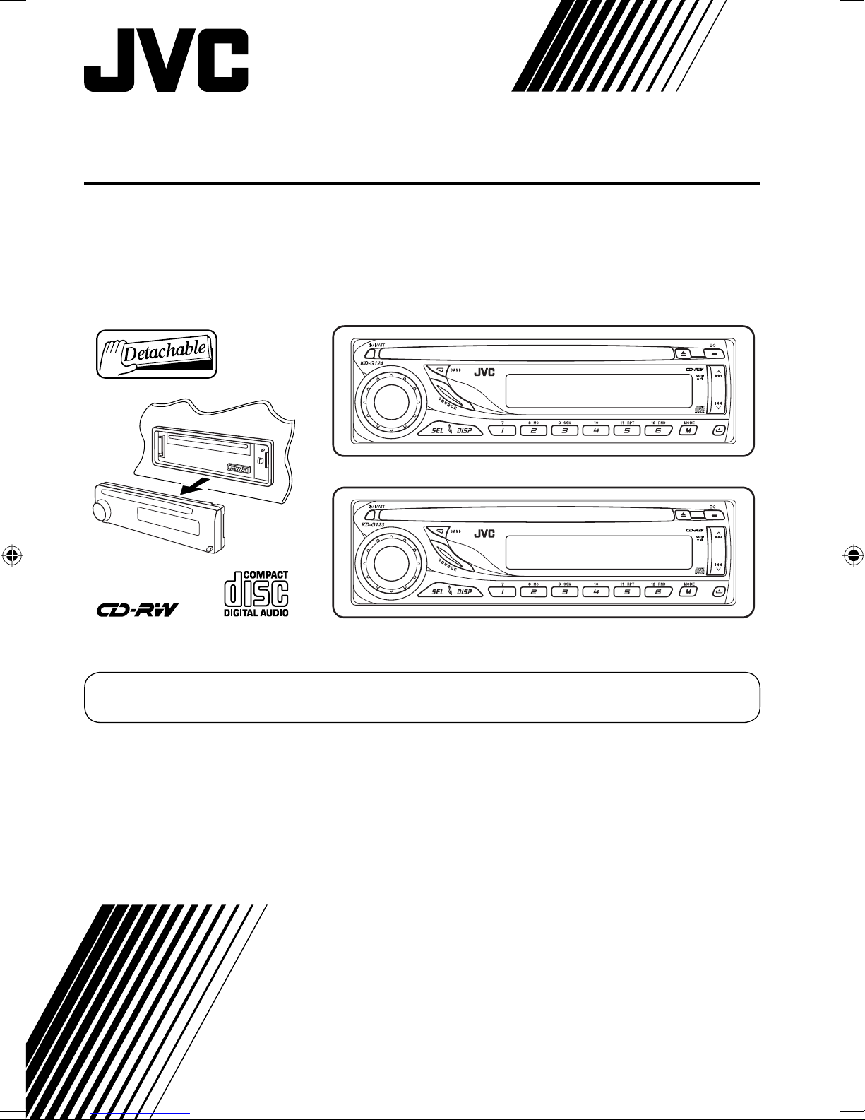
CD RECEIVER
KD-G124/KD-G123
KD-G124
KD-G123
For canceling the display demonstration, see page 5.
For installation and connections, refer to the separate manual.
INSTRUCTIONS
GET0332-001A
[UI]
Page 20
Thank you for purchasing a JVC product.
Please read all instructions carefully before operation, to ensure your complete understanding and to
obtain the best possible performance from the unit.
IMPORTANT FOR LASER PRODUCTS
1. CLASS 1 LASER PRODUCT
2. CAUTION: Do not open the top cover. There are no user serviceable parts inside the unit; leave
all servicing to qualified service personnel.
3. CAUTION: Visible and invisible laser radiation when open and interlock failed or defeated.
Avoid direct exposure to beam.
4. REPRODUCTION OF LABEL: CAUTION LABEL, PLACED OUTSIDE THE UNIT.
Warning:
If you need to operate the unit while driving,
be sure to look ahead carefully or you may be
involved in a traffic accident.
How to reset your unit
• Your preset adjustments will also be erased.
• If a disc is loaded, it will eject. Be careful not to
drop the disc.
How to forcibly eject a disc
Caution on volume setting:
Discs produce very little noise compared
with other sources. Lower the volume
before playing a disc to avoid damaging
the speakers by the sudden increase of the
output level.
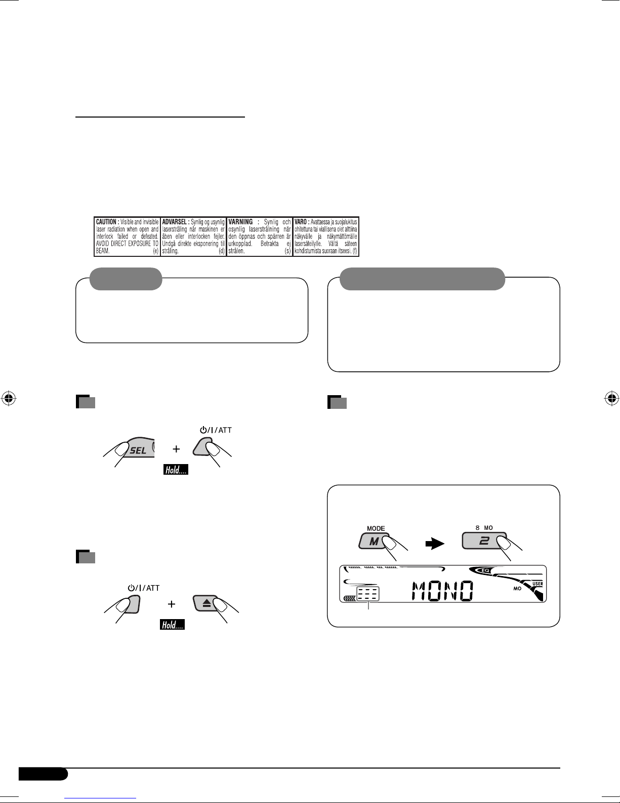
How to use the M MODE button
If you press M MODE, the unit goes into
functions mode, then the number buttons work
as different function buttons.
Ex.: When number button 2 works as
MO (monaural) button.
• If this does not work, reset your unit.
• Be careful not to drop the disc when it ejects.
2
Time countdown indicator
To use these buttons for their original
functions again after pressing M MODE, wait
for 5 seconds without pressing any of these
buttons until the functions mode is cleared or
press M MODE again.
Page 21
How to read this manual
• Button operations are mainly explained with
the illustrations in the table below.
•
• Some related tips and notes are explained in
is used to indicate an indicator is
displayed for the corresponding operation.
“More about this unit” (see pages 11 and 12).
CONTENTS
Control panel — KD-G124 and KD-G123 ........ 4
Getting started ................................. 5
Basic operations .................................................... 5
Radio operations .............................. 6
Press briefly.
Press repeatedly.
Press either
one.
Press and hold until your
desired response begins.
Press and hold both
buttons at the same time.
How to detach/attach the control
panel
Disc operations ................................. 7
Playing a disc in the unit ....................................... 7
Sound adjustments ........................... 8
General settings — PSM ................... 9
Maintenance .................................... 10
More about this unit ......................... 11
Troubleshooting ............................... 12
Specifications ................................... 13
Detaching...
Attaching...
For safety...
• Do not raise the volume level too much, as
this will block outside sounds, making driving
dangerous.
• Stop the car before performing any
complicated operations.
Temperature inside the car...
If you have parked the car for a long time in hot
or cold weather, wait until the temperature in
the car becomes normal before operating the
unit.
3
Page 22
Control panel — KD-G124 and KD-G123
Parts identification
Display window
1 (standby/on/attenuator) button
2 SOURCE button
3 BAND button
4 Loading slot
5 Display window
6 0 (eject) button
7 EQ (equalizer) button
8
9 Control dial
p SEL (select) button
q DISP (display) button
w MO (monaural) button
e SSM (Strong-station Sequential Memory)
r Number buttons
t RPT (repeat) button
y RND (random) button
u M MODE button
i
¢/4 buttons
button
(control panel release) button
Display window
o DISC indicator
; RND
a RPT (repeat) indicator
s S. BASS (super bass) indicator
d EQ (equalizer) indicator
f Sound mode (C-EQ: custom equalizer)
indicators—JAZZ, CLASSIC, HIP HOP,
POPS, ROCK, USER
g Source display
Volume level indicator
Time countdown indicator
h Main display
j Tuner reception indicators—ST (stereo),
MO (monaural)
(disc random) indicator
4
Page 23
Getting started
Basic operations
Basic settings
• See also “General settings — PSM” on page 9.
~ Turn on the power.
Ÿ
* You cannot select “DISC” as the
playback source if there is no disc in the
loading slot.
! For FM/AM tuner
⁄ Adjust the volume.
1
2
1 Canceling the display
demonstrations
Select “DEMO,” then “DEMO OFF.”
2 Setting the clock
Select “CLOCK H” (hour), then adjust
the hour.
Select “CLOCK M” (minute), then
adjust the minute.
3 Finish the procedure.
.
Volume level indicator
@ Adjust the sound as you want. (See
page 8.)
To drop the volume in a
moment (ATT)
To restore the sound,
press it again.
To turn off the power
Volume level appears.
To check the current clock
time while the power is
turned off
To check the other
information while
listening to the radio/a
disc
Frequency/Elapsed playing time
Ô Clock
5
Page 24

Radio operations
~
Ÿ
When an FM stereo broadcast is hard to
receive
Lights up when monaural mode is activated.
Lights up when receiving an FM stereo
broadcast with sufficient signal strength.
Selected band appears.
! Start searching for a station.
When a station is received,
searching stops.
To stop searching, press the
same button again.
To tune in to a station manually
In step ! above...
1
Reception improves, but stereo effect will be
lost.
To restore the stereo effect, repeat the same
procedure “MONO OFF” appears and the MO
indicator goes off.
Storing stations in memory
You can preset six stations for each band.
FM station automatic presetting —
SSM (Strong-station Sequential
Memory)
1 Select the FM band (FM1 – FM3) you
want to store into.
2 Select the desired station frequencies.
6
2
3
“SSM” flashes, then disappears when
automatic presetting is over.
Local FM stations with the strongest signals are
searched and stored automatically in the FM
band.
Page 25

Manual presetting
Ex.: Storing FM station of 92.5 MHz into preset
number 4 of the FM1 band.
1
2
Disc operations
Playing a disc in the unit
All tracks will be played repeatedly until you
change the source or eject the disc.
To stop play and eject the
3
Preset number flashes for a while.
Listening to a preset station
1
2 Select the preset station (1 – 6) you
want.
disc
To fast-forward or reverse
the track
To go to the next or
previous tracks
To locate a particular track directly
To select a number from 01 – 06:
To select a number from 07 – 12:
Prohibiting disc ejection
You can lock a disc in the loading slot.
To cancel the prohibition, repeat the same
procedure.
7
Page 26
Selecting the playback modes
Adjusting the sound
You can use only one of the following playback
modes at a time.
1
2 Select your desired playback mode.
7 Repeat play
Mode Plays repeatedly
TRK RPT : The current track.
RPT OFF : Cancels.
7 Random play
Mode Plays at random
DISC RND : All tracks of the current disc.
You can adjust the sound characteristics to your
preference.
1
*
Displayed only when “L/O MODE” is set to
“WOOFER” (see page 9).
Indication, [Range]
BAS*2 (bass), [–06 to +06]
Adjust the bass.
2
TRE*
(treble), [–06 to +06]
Adjust the treble.
3
FAD*
Adjust the front and rear speaker balance.
(fader), [R06 to F06]
RND OFF : Cancels.
Sound adjustments
You can select a preset sound mode suitable to
the music genre (C-EQ: custom equalizer).
Preset values
Indication (For)
USER (Flat sound)
ROCK
(Rock or disco music)
CLASSIC
(Classical music)
POPS (Light music)
HIP HOP
(Funk or rap music)
JAZZ (Jazz music)
BAS TRE S.BS
(bass) (treble)
00 00 OFF
+03 +01 ON
+01 –02 OFF
+04 +01 OFF
+02 00 ON
+02 +03 OFF
(super
bass)
4
BAL*
(balance), [L06 to R06]
Adjust the left and right speaker balance.
S.BS*2 (super bass), [S.BS ON or S.BS OFF]
[01 to 05]
5
*
Maintain the richness and fullness of the bass
sound regardless of how low you set the volume.
SUB. W
(subwoofer), [00 to 08]
Adjust the subwoofer output level when a
subwoofer is connected.
6
VOL (volume), [00 to 30 or 50*
]
Adjust the volume.
2
*
When you adjust the bass, treble, or
super bass the adjustment you have made is
stored for the currently selected sound mode
(C-EQ) including “USER.”
3
*
If you are using a two-speaker system, set the
fader level to “00.”
4
*
This adjustment cannot affect the subwoofer
output.
5
*
Range adjustment for super bass is adjustable
only when it is set to “S.BS ON.”
6
*
Depending on the amplifier gain control
setting. (See page 9 for details.)
8
Page 27

General settings — PSM
You can change PSM (Preferred Setting Mode)
items listed in the table that follows.
3 Adjust the PSM item selected.
1
4 Repeat steps 2 and 3 to adjust other
2 Select a PSM item.
PSM items if necessary.
5 Finish the procedure.
Indications Selectable settings, [reference page]
DEMO
Display
demonstration
CLOCK H
Hour adjustment
CLOCK M
Minute adjustment
L/O MODE
Line output mode
AMP GAIN
Amplifier gain
control
DEMO ON : [Initial]; Display demonstration will be activated automatically
if no operation is done for about 20 seconds, [5].
DEMO OFF : Cancels.
1 – 12, [5]
[Initial: 1 (1:00)]
00 – 59, [5]
[Initial: 00 (1:00)]
When connecting an amplifier or a subwoofer, set this correctly.
REAR : [Initial]; Select if the REAR LINE OUT terminals are used for
connecting the speakers through an external amplifier.
WOOFER : Select if the REAR LINE OUT terminals are used for
connecting a subwoofer.
You can change the maximum volume level of this unit.
LOW PWR : VOL 00 – VOL 30 (Select this if the maximum power of the
speaker is less than 50 W to avoid damaging the speaker.)
HIGH PWR : [Initial]; VOL 00 – VOL 50
9
Page 28

Maintenance
How to clean the connectors
Frequent detachment will deteriorate the
connectors. To minimize this possibility,
periodically wipe the connectors with a cotton
swab or cloth moistened with alcohol, being
careful not to damage the connectors.
Connector
Moisture condensation
Moisture may condense on the lens inside the
CD player in the following cases:
• After starting the heater in the car.
• If it becomes very humid inside the car.
Should this occur, the CD player may
malfunction. In this case, eject the disc and
leave the unit turned on for a few hours until
the moisture evaporates.
To play new discs
New discs may have some rough
spots around the inner and outer
edges. If such a disc is used, this
unit may reject the disc.
To remove these rough spots, rub the edges
with a pencil or ball-point pen, etc.
To keep discs clean
A dirty disc may not play correctly.
If a disc does become dirty, wipe it
with a soft cloth in a straight line
from center to edge.
• Do not use any solvent (for example,
conventional record cleaner, spray, thinner,
benzine, etc.) to clean discs.
Do not use the following discs:
Warped disc
How to handle discs
When removing a disc from
its case, press down the center
holder of the case and lift the disc
out, holding it by the edges.
• Always hold the disc by the
edges. Do not touch its recording surface.
When storing a disc into its case, gently insert
the disc around the center holder (with the
printed surface facing up).
• Make sure to store discs into the cases after
use.
Center holder
Sticker
Disc
Sticker residue
Stick-on label
10
Page 29

More about this unit
Basic operations
Turning on the power
• By pressing SOURCE on the unit, you can
also turn on the power. If the source is ready,
playback also starts.
Turning off the power
• If you turn off the power while listening to a
disc, disc play will start from where playback
has been stopped previously, next time you
turn on the power.
Selecting the sources
• When no disc is loaded in the unit, “DISC”
cannot be selected.
Tuner operations
Storing stations in memory
• During SSM search...
– All previously stored stations are erased and
stations are stored newly.
–
Received stations are preset in No. 1 (lowest
frequency) to No. 6 (highest frequency).
– When SSM is over, the station stored in
No. 1 will be automatically tuned in.
• When storing a station manually, a previously
preset station is erased when a new station is
stored in the same preset number.
Disc operations
Caution for DualDisc playback
• The Non-DVD side of a “DualDisc” does
not comply with the “Compact Disc Digital
Audio” standard. Therefore, the use of NonDVD side of a DualDisc on this product may
not be recommended.
General
• This unit has been designed to reproduce
CDs, and CD-Rs (Recordable)/CD-RWs
(Rewritable) in audio CD (CD-DA) format.
• When a disc has been loaded, selecting
“DISC” for the playback source starts disc
play.
Inserting a disc
• When a disc is inserted upside down, the disc
automatically ejects.
• Do not insert 8 cm discs (single CD) and
unusual shape discs (heart, flower, etc.) into
the loading slot.
Playing a CD-R or CD-RW
• Use only “finalized” CD-Rs or CD-RWs.
• This unit can play back multi-session discs;
however, unclosed sessions will be skipped
while playing.
• Some CD-Rs or CD-RWs may not play
back on this unit because of their disc
characteristics, and for the following causes:
– Discs are dirty or scratched.
– Moisture condensation occurs on the lens
inside the unit.
– The pickup lens inside the unit is dirty.
– CD-R/CD-RW on which the files are
written with “Packet Write” method.
– There are improper recording conditions
(missing data, etc.) or media conditions
(stain, scratch, warp, etc.).
• CD-RWs may require a longer readout time
since the reflectance of CD-RWs is lower than
that of regular CDs.
• Do not use the following CD-Rs or CD-RWs:
– Discs with stickers, labels, or protective seal
stuck to the surface.
– Discs on which labels can be directly
printed by an ink jet printer.
Using these discs under high temperatures
or high humidity may cause malfunctions or
damages to the unit.
Changing the source
• If you change the source, playback also stops
(without ejecting the disc).
Next time you select “DISC” for the playback
source, disc play starts from where it has been
stopped previously.
To be continued...
11
Page 30

Ejecting a disc
General settings—PSM
• If the ejected disc is not removed within
15 seconds, the disc is automatically inserted
again into the loading slot to protect it from
dust. (Disc will not play this time.)
• If you change the “AMP GAIN” setting from
“HIGH PWR” to “LOW PWR” while the
volume level is set higher than “VOL 30,” the
unit automatically changes the volume level to
“VOL 30.”
Troubleshooting
What appears to be trouble is not always serious. Check the following points before calling a service
center.
Symptoms Remedies/Causes
• Sound cannot be heard from the
speakers.
General
• This unit does not work at all. Reset the unit (see page 2).
• SSM automatic presetting does not
work.
• Adjust the volume to the optimum level.
• Check the cords and connections.
Store stations manually.
• Static noise while listening to the
FM/AM
radio.
• Disc automatically ejects. Insert the disc correctly.
• CD-R/CD-RW cannot be played
back.
• Tracks on the CD-R/CD-RW cannot
be skipped.
• Disc can be neither played back nor
ejected.
Disc playback
• Disc sound is sometimes interrupted. • Stop playback while driving on rough roads.
• “NO DISC” appears on the display. Insert a playable disc into the loading slot.
Connect the antenna firmly.
• Insert a finalized CD-R/CD-RW.
•
Finalize the CD-R/CD-RW with the component
which you used for recording.
• Unlock the disc (see page 7).
• Eject the disc forcibly (see page 2).
• Change the disc.
• Check the cords and connections.
12
Page 31

Specifications
AUDIO AMPLIFIER SECTION
Maximum Power Output:
Front: 50 W per channel
Rear: 50 W per channel
Continuous Power Output (RMS):
Front: 19 W per channel into 4 Ω, 40 Hz
to 20 000 Hz at no more than 0.8%
total harmonic distortion.
Rear: 19 W per channel into 4 Ω, 40 Hz
to 20 000 Hz at no more than 0.8%
total harmonic distortion.
Load Impedance: 4 Ω (4 Ω to 8 Ω allowance)
Tone Control Range:
Bass: ±10 dB at 100 Hz
Treble: ±10 dB at 10 kHz
Frequency Response: 40 Hz to 20 000 Hz
Signal to Noise Ratio: 70 dB
Line-Out Level/Impedance:
2.0 V/20 kΩ load (full scale)
Output Impedance: 1 kΩ
Subwoofer-Out Level/Impedance:
2.0 V/20 kΩ load (full scale)
TUNER SECTION
CD PLAYER SECTION
Type: Compact disc player
Signal Detection System: Non-contact optical
pickup (semiconductor laser)
Number of channels: 2 channels (stereo)
Frequency Response: 5 Hz to 20 000 Hz
Dynamic Range: 96 dB
Signal-to-Noise Ratio: 98 dB
Wow and Flutter: Less than measurable limit
GENERAL
Power Requirement:
Operating Voltage:
Grounding System: Negative ground
Allowable Operating Temperature:
0°C to +40°C
Dimensions (W × H × D):
Installation Size (approx.):
182 mm × 52 mm × 150 mm
Panel Size (approx.):
188 mm × 58 mm × 11 mm
Mass (approx.):
1.2 kg (excluding accessories)
DC 14.4 V (11 V to 16 V allowance)
Frequency Range:
FM: 87.5 MHz to 108.0 MHz
AM: 531 kHz to 1 602 kHz
[FM Tuner]
Usable Sensitivity: 11.3 dBf (1.0 μV/75 Ω)
50 dB Quieting Sensitivity:
16.3 dBf (1.8 μV/75 Ω)
Alternate Channel Selectivity (400 kHz): 65 dB
Frequency Response: 40 Hz to 15 000 Hz
Stereo Separation: 35 dB
Capture Ratio: 1.5 dB
[AM Tuner]
Sensitivity: 20 μV
Selectivity: 35 dB
Design and specifications are subject to change
without notice.
13
Page 32
Having TROUBLE with operation?
Please reset your unit
Refer to page of How to reset your unit
EN
© 2005 Victor Company of Japan, Limited
1005DTSMDTJEIN
Page 33

KD-G124/KD-G123
Installation/Connection Manual
GET0332-002A
[UI]
1005DTSMDTJEIN
EN
This unit is designed to operate on 12 V DC, NEGATIVE ground electrical systems. If your vehicle does not have this system, a voltage inverter is required, which can be purchased at JVC car audio dealers.
1
© 2005 Victor Company of Japan, Limited
WARNINGS
To prevent short circuits, we recommend that you disconnect the battery’s negative terminal and make all electrical connections before installing the unit.
• Be sure to ground this unit to the car’s chassis again after installation.
Notes:
• Replace the fuse with one of the specified rating. If the fuse blows frequently, consult your JVC car audio dealer.
• It is recommended to connect to the speakers with maximum power of more than 50 W (both at the rear and at the front, with an impedance of
4 Ω to 8 Ω). If
the maximum power is less than 50 W, change “AMP GAIN” setting to prevent the speakers from being damaged (see page 9 of the INSTRUCTIONS).
• To prevent short-circuit, cover the terminals of the UNUSED leads with insulating tape.
• The heat sink becomes very hot after use. Be careful not to touch it when removing this unit.
Heat sink
PRECAUTIONS on power supply and speaker connections:
• DO NOT connect the speaker leads of the power cord to the car battery; otherwise, the unit
will be seriously damaged.
• BEFORE connecting the speaker leads of the power cord to the speakers, check the speaker wiring in
your car.
J
Handles
F
Washer (ø5)
G
Lock nut (M5)
H
Mounting bolt (M5 × 20 mm)
I
Rubber cushion
A / B
Hard case/Control panel
D
Trim plate
E
Power cord
Parts list for installation and connection
The following parts are provided for this unit.
After checking them, please set them correctly.
C
Sleeve
INSTALLATION (IN-DASH MOUNTING)
The following illustration shows a typical installation. If you have any questions or require information regarding installation kits, consult your JVC car audio dealer or a company supplying kits.
• If you are not sure how to install this unit correctly, have it installed by a qualified technician.
Do the required electrical connections.
*
1
When you stand the unit, be careful not to
damage the fuse on the rear.
Bend the appropriate tabs to hold the
sleeve firmly in place.
Removing the unit
Before removing the unit, release the rear section.
When installing the unit without using the sleeve
In a Toyota car for example, first remove the car radio and install the unit in its place.
When using the optional stay
Note : When installing the unit on the mounting bracket, make sure to use the 8 mm-long screws. If longer screws are
used, they could damage the unit.
Bracket*
Bracket*
* Not supplied for this unit.
Flat type screws (M5 × 8 mm)*
Pocket
Flat type screws (M5 × 8 mm)
*
Screw (option)
Stay (option)
Fire wall
Dashboard
Install the unit at an angle of less than 30˚.
Insert the two handles, then pull them as illustrated so that
the unit can be removed.
Page 34

Typical connections
Before connecting:
Check the wiring in the vehicle carefully. Incorrect connection may cause serious damage to this unit.
The leads of the power cord and those of the connector from the car body may be different in color.
1 Connect the colored leads of the power cord in the order specified in the illustration below.
2 Connect the antenna cord.
3 Finally connect the wiring harness to the unit.
A
ELECTRICAL CONNECTIONS
15
TROUBLESHOOTING
• The fuse blows.
* Are the red and black leads connected correctly?
• Power cannot be turne d on.
* Is the yellow lead connected?
• No sound from the speaker s.
* Is the speaker output lead short-circuited?
• Sound is distor ted.
* Is the speaker output lead grounded?
* Are the “–” terminals of L and R speakers grounded in common?
• Noise interfere wit h sounds.
* Is the rear ground terminal connected to the car’s chassis using shorter and thicker cords?
• This unit becomes hot.
* Is the speaker output lead grounded?
* Are the “–” terminals of L and R speakers grounded in common?
• This unit does not work at all .
* Have you reset your unit?
Connecting the external amplifi er or subwoofer
You can connect an amplifier to upgrade your car stereo system.
• Connect the remote lead (blue with white stripe) to the remote lead of the other
equipment so that it can be controlled through this unit.
• Disconnect the speakers from this unit, connect them to the amplifier. Leave the
speaker leads of this unit unused.
B
*
3
Firmly attach the ground wire to the metallic body or to the chassis of the car—to the
place uncoated with paint (if coated with paint, remove the paint before attaching the
wire). Failure to do so may cause damage to the unit.
*
4
Signal cord (not supplied for this unit)
KD-G124
KD-G123
Set “L/O MODE” to “REAR” (See page 9 of
the INSTRUCTIONS.)
Set “L/O MODE” to “WOOFER”
(See page 9 of the
INSTRUCTIONS.)
Y-connector (not supplied for this unit)
Remote lead
Remote lead (Blue with white stripe)
To the remote lead of other equipment or automatic antenna if any
Front speakers
You can connect a power amplifier for rear
speakers.
You can also connect a
subwoofer to the REAR
LINE OUT terminals.
Subwoofer
JVC Amplifie r
JVC Amplifie r
Rear speakers
Rear ground
terminal
Antenna terminal
15 A fuse
Line out (see diagram
)
*
1
Not supplied for this unit.
Ignition switch
To the automatic antenna if any (250 mA max.)
To the remote lead of other equipment (200 mA max.)
To metallic body or chassis of the car
To a live terminal in the fuse block connecting to the car battery
(bypassing the ignition switch) (constant 12 V)
To an accessory terminal in the fuse block
Black
Blue with white stripe
Red
Yellow
*
2
Blue
Purple
Purple with black stripeGreen
Green with black stripe
GrayGray with black stripe
White
White with black
stripe
*
2
Before checking the operation of this unit prior to
installation, this lead must be connected, otherwise
power cannot be turned on.
Right speaker (rear)Left speaker (rear)
Right speaker (front)Left speaker (front)
2
Fuse block
Page 35

CD RECEIVER KD-G126/KD-G125
KD-G126/KD-G125
KD-G126
KD-G126
KD-G125
KD-G125
ENGLISH
For canceling the display demonstration, see page 5.
5
For installation and connections, refer to the separate manual.
INSTRUCTIONS
GET0331-001A
[U/UH]
Page 36

Thank you for purchasing a JVC product.
Please read all instructions carefully before operation, to ensure your complete understanding and to
obtain the best possible performance from the unit.
IMPORTANT FOR LASER PRODUCTS
ENGLISH
1. CLASS 1 LASER PRODUCT
2. CAUTION: Do not open the top cover. There are no user serviceable parts inside the unit; leave
all servicing to qualified service personnel.
3. CAUTION: Visible and invisible laser radiation when open and interlock failed or defeated.
Avoid direct exposure to beam.
4. REPRODUCTION OF LABEL: CAUTION LABEL, PLACED OUTSIDE THE UNIT.
Warning:
If you need to operate the unit while driving,
be sure to look ahead carefully or you may be
involved in a traffic accident.
How to reset your unit
• Your preset adjustments will also be erased.
• If a disc is loaded, it will eject. Be careful not to
drop the disc.
How to forcibly eject a disc
Caution on volume setting:
Discs produce very little noise compared
with other sources. Lower the volume
before playing a disc to avoid damaging
the speakers by the sudden increase of the
output level.
How to use the M MODE button
If you press M MODE, the unit goes into
functions mode, then the number buttons work
as different function buttons.
Ex.: When number button 2 works as
MO (monaural) button.
• If this does not work, reset your unit.
• Be careful not to drop the disc when it ejects.
2
Time countdown indicator
To use these buttons for their original
functions again after pressing M MODE, wait
for 5 seconds without pressing any of these
buttons until the functions mode is cleared or
press M MODE again.
Page 37

How to read this manual
• Button operations are mainly explained with
the illustrations in the table below.
•
• Some related tips and notes are explained in
is used to indicate an indicator is
displayed for the corresponding operation.
“More about this unit” (see pages 11 and 12).
CONTENTS
Control panel — KD-G126 and KD-G125 ........ 4
Getting started ................................. 5
Basic operations .................................................... 5
Radio operations .............................. 6
ENGLISH
Press briefly.
Press repeatedly.
Press either
one.
Press and hold until your
desired response begins.
Press and hold both
buttons at the same time.
How to detach/attach the control
panel
Disc operations ................................. 7
Playing a disc in the unit ....................................... 7
Sound adjustments ........................... 8
General settings — PSM ................... 9
Maintenance .................................... 10
More about this unit ......................... 11
Troubleshooting ............................... 12
Specifications ................................... 13
Detaching...
Attaching...
For safety...
• Do not raise the volume level too much, as
this will block outside sounds, making driving
dangerous.
• Stop the car before performing any
complicated operations.
Temperature inside the car...
If you have parked the car for a long time in hot
or cold weather, wait until the temperature in
the car becomes normal before operating the
unit.
3
Page 38

Control panel — KD-G126 and KD-G125
Parts identification
ENGLISH
Display window
1 (standby/on/attenuator) button
2 SOURCE button
3 BAND button
4 Loading slot
5 Display window
6 0 (eject) button
7 EQ (equalizer) button
8
9 Control dial
p SEL (select) button
q DISP (display) button
w MO (monaural) button
e SSM (Strong-station Sequential Memory)
r Number buttons
t RPT (repeat) button
y RND (random) button
u M MODE button
i
¢/4 buttons
button
(control panel release) button
Display window
o DISC indicator
; RND
a RPT (repeat) indicator
s S. BASS (super bass) indicator
d EQ (equalizer) indicator
f Sound mode (C-EQ: custom equalizer)
indicators—JAZZ, CLASSIC, HIP HOP,
POPS, ROCK, USER
g Source display
Volume level indicator
Time countdown indicator
h Main display
j Tuner reception indicators— ST (stereo),
MO (monaural)
(disc random) indicator
4
Page 39

Getting started
Basic operations
Basic settings
• See also “General settings — PSM” on page 9.
~ Turn on the power.
Ÿ
* You cannot select “DISC” as the
playback source if there is no disc in the
loading slot.
! For FM/AM tuner
⁄ Adjust the volume.
1
ENGLISH
2
1 Canceling the display
demonstrations
Select “DEMO,” then “DEMO OFF.”
2 Setting the clock
Select “CLOCK H” (hour), then adjust
the hour.
Select “CLOCK M” (minute), then
adjust the minute.
3 Finish the procedure.
.
Volume level indicator
@ Adjust the sound as you want. (See
page 8.)
To drop the volume in a
moment (ATT)
To restore the sound, press
it again.
To turn off the power
Volume level appears.
To check the current clock
time while the power is
turned off
To check the other
information while listening
to the radio/a disc
Frequency/Elapsed playing time
Ô Clock
5
Page 40

Radio operations
~
ENGLISH
Ÿ
When an FM stereo broadcast is hard to
receive
Lights up when monaural mode is activated.
Lights up when receiving an FM stereo
broadcast with sufficient signal strength.
Selected band appears.
! Start searching for a station.
When a station is received,
searching stops.
To stop searching, press the
same button again.
To tune in to a station manually
In step ! above...
1
Reception improves, but stereo effect will be
lost.
To restore the stereo effect, repeat the same
procedure “MONO OFF” appears and the MO
indicator goes off.
Storing stations in memory
You can preset six stations for each band.
FM station automatic presetting —
SSM (Strong-station Sequential
Memory)
1 Select the FM band (FM1 – FM3) you
want to store into.
2 Select the desired station frequencies.
6
2
3
“SSM” flashes, then disappears when
automatic presetting is over.
Local FM stations with the strongest signals are
searched and stored automatically in the FM
band.
Page 41

Manual presetting
Ex.: Storing FM station of 92.5 MHz into preset
number 4 of the FM1 band.
1
2
Disc operations
Playing a disc in the unit
ENGLISH
All tracks will be played repeatedly until you
change the source or eject the disc.
To stop play and eject the
3
Preset number flashes for a while.
Listening to a preset station
1
2 Select the preset station (1 – 6) you
want.
disc
To fast-forward or reverse
the track
To go to the next or
previous tracks
To locate a particular track directly
To select a number from 01 – 06:
To select a number from 07 – 12:
Prohibiting disc ejection
You can lock a disc in the loading slot.
To cancel the prohibition, repeat the same
procedure.
7
Page 42

Selecting the playback modes
Adjusting the sound
You can use only one of the following playback
modes at a time.
1
ENGLISH
2 Select your desired playback mode.
7 Repeat play
Mode Plays repeatedly
TRK RPT : The current track.
RPT OFF : Cancels.
7 Random play
Mode Plays at random
DISC RND : All tracks of the current disc.
You can adjust the sound characteristics to your
preference.
1
*
Displayed only when “L/O MODE” is set to
“WOOFER” (see page 9).
Indication, [Range]
BAS*2 (bass), [–06 to +06]
Adjust the bass.
2
TRE*
(treble), [–06 to +06]
Adjust the treble.
3
FAD*
Adjust the front and rear speaker balance.
(fader), [R06 to F06]
RND OFF : Cancels.
Sound adjustments
You can select a preset sound mode suitable to
the music genre (C-EQ: custom equalizer).
Preset values
Indication (For)
USER (Flat sound)
ROCK
(Rock or disco music)
CLASSIC
(Classical music)
POPS (Light music)
HIP HOP
(Funk or rap music)
JAZZ (Jazz music)
BAS TRE S.BS
(bass) (treble)
00 00 OFF
+03 +01 ON
+01 –02 OFF
+04 +01 OFF
+02 00 ON
+02 +03 OFF
(super
bass)
4
BAL*
(balance), [L06 to R06]
Adjust the left and right speaker balance.
S.BS*2 (super bass), [S.BS ON or S.BS OFF],
[01 to 05]
Maintain the richness and fullness of the bass
sound regardless of how low you set the volume.
SUB. W
Adjust the subwoofer output level when a
subwoofer is connected.
VOL (volume), [00 to 30 or 50*
Adjust the volume.
2
*
When you adjust the bass, treble, or
3
*
If you are using a two-speaker system, set the
4
*
This adjustment cannot affect the subwoofer
5
*
Range adjustment for super bass is adjustable
6
*
Depending on the amplifier gain control
(subwoofer), [00 to 08]
super bass the adjustment you have made is
stored for the currently selected sound mode
(C-EQ) including “USER.”
fader level to “00.”
output.
only when it is set to “S.BS ON.”
setting. (See page 9 for details.)
5
*
6
]
8
Page 43

General settings — PSM
You can change PSM (Preferred Setting Mode)
items listed in the table that follows.
3 Adjust the PSM item selected.
1
4 Repeat steps 2 and 3 to adjust other
2 Select a PSM item.
PSM items if necessary.
5 Finish the procedure.
Indications Selectable settings, [reference page]
ENGLISH
DEMO
Display
demonstration
CLOCK H
Hour adjustment
CLOCK M
Minute adjustment
L/O MODE
Line output mode
AMP GAIN
Amplifier gain
control
DEMO ON : [Initial]; Display demonstration will be activated automatically
if no operation is done for about 20 seconds, [5].
DEMO OFF : Cancels.
1 – 12, [5]
[Initial: 1 (1:00)]
00 – 59, [5]
[Initial: 00 (1:00)]
When connecting an amplifier or a subwoofer, set this correctly.
REAR : [Initial]; Select if the REAR LINE OUT terminals are used for
connecting the speakers through an external amplifier.
WOOFER : Select if the REAR LINE OUT terminals are used for
connecting a subwoofer.
You can change the maximum volume level of this unit.
LOW PWR : VOL 00 – VOL 30 (Select this if the maximum power of the
speaker is less than 50 W to avoid damaging the speaker.)
HIGH PWR : [Initial]; VOL 00 – VOL 50
9
Page 44

Maintenance
How to clean the connectors
Frequent detachment will deteriorate the
connectors.To minimize this possibility,
ENGLISH
periodically wipe the connectors with a cotton
swab or cloth moistened with alcohol, being
careful not to damage the connectors.
Connector
Moisture condensation
Moisture may condense on the lens inside the
CD player in the following cases:
• After starting the heater in the car.
• If it becomes very humid inside the car.
Should this occur, the CD player may
malfunction.In this case, eject the disc and leave
the unit turned on for a few hours until the
moisture evaporates.
To play new discs
New discs may have some rough
spots around the inner and outer
edges. If such a disc is used, this
unit may reject the disc.
To remove these rough spots, rub the edges
with a pencil or ball-point pen, etc.
To keep discs clean
A dirty disc may not play correctly.
If a disc does become dirty, wipe it
with a soft cloth in a straight line
from center to edge.
• Do not use any solvent (for example,
conventional record cleaner, spray, thinner,
benzine, etc.) to clean discs.
Do not use the following discs:
Warped disc
How to handle discs
When removing a disc from
its case, press down the center
holder of the case and lift the disc
out, holding it by the edges.
• Always hold the disc by the
edges. Do not touch its recording surface.
When storing a disc into its case, gently insert
the disc around the center holder (with the
printed surface facing up).
• Make sure to store discs into the cases after
use.
Center holder
Sticker
Disc
Sticker residue
Stick-on label
10
Page 45

More about this unit
Basic operations
Turning on the power
• By pressing SOURCE on the unit, you can
also turn on the power. If the source is ready,
playback also starts.
Turning off the power
• If you turn off the power while listening to a
disc, disc play will start from where playback
has been stopped previously, next time you
turn on the power.
Selecting the sources
• When no disc is loaded in the unit, “DISC”
cannot be selected.
Tuner operations
Storing stations in memory
• During SSM search...
– All previously stored stations are erased and
stations are stored newly.
–
Received stations are preset in No. 1 (lowest
frequency) to No. 6 (highest frequency).
– When SSM is over, the station stored in
No. 1 will be automatically tuned in.
• When storing a station manually, a previously
preset station is erased when a new station is
stored in the same preset number.
Disc operations
Caution for DualDisc playback
• The Non-DVD side of a “DualDisc” does
not comply with the “Compact Disc Digital
Audio” standard. Therefore, the use of NonDVD side of a DualDisc on this product may
not be recommended.
General
• This unit has been designed to reproduce
CDs, and CD-Rs (Recordable)/CD-RWs
(Rewritable) in audio CD (CD-DA) format.
• When a disc has been loaded, selecting
“DISC” for the playback source starts disc
play.
Inserting a disc
• When a disc is inserted upside down, the disc
automatically ejects.
• Do not insert 8 cm discs (single CD) and
unusual shape discs (heart, flower, etc.) into
the loading slot.
Playing a CD-R or CD-RW
• Use only “finalized” CD-Rs or CD-RWs.
• This unit can play back multi-session discs;
however, unclosed sessions will be skipped
while playing.
• Some CD-Rs or CD-RWs may not play
back on this unit because of their disc
characteristics, and for the following causes:
– Discs are dirty or scratched.
– Moisture condensation occurs on the lens
inside the unit.
– The pickup lens inside the unit is dirty.
– CD-R/CD-RW on which the files are
written with “Packet Write” method.
– There are improper recording conditions
(missing data, etc.) or media conditions
(stain, scratch, warp, etc.).
• CD-RWs may require a longer readout time
since the reflectance of CD-RWs is lower than
that of regular CDs.
• Do not use the following CD-Rs or CD-RWs:
– Discs with stickers, labels, or protective seal
stuck to the surface.
– Discs on which labels can be directly
printed by an ink jet printer.
Using these discs under high temperatures
or high humidity may cause malfunctions or
damages to the unit.
Changing the source
• If you change the source, playback also stops
(without ejecting the disc).
Next time you select “DISC” for the playback
source, disc play starts from where it has been
stopped previously.
To be continued...
ENGLISH
11
Page 46

Ejecting a disc
General settings—PSM
• If the ejected disc is not removed within
15 seconds, the disc is automatically inserted
again into the loading slot to protect it from
dust. (Disc will not play this time.)
ENGLISH
• If you change the “AMP GAIN” setting from
“HIGH PWR” to “LOW PWR” while the
volume level is set higher than “VOL 30,” the
unit automatically changes the volume level to
“VOL 30.”
Troubleshooting
What appears to be trouble is not always serious. Check the following points before calling a service
center.
Symptoms Remedies/Causes
• Sound cannot be heard from the
speakers.
General
• This unit does not work at all. Reset the unit (see page 2).
• SSM automatic presetting does not
work.
• Adjust the volume to the optimum level.
• Check the cords and connections.
Store stations manually.
• Static noise while listening to the
FM/AM
radio.
• Disc automatically ejects. Insert the disc correctly.
• CD-R/CD-RW cannot be played
back.
• Tracks on the CD-R/CD-RW cannot
be skipped.
• Disc can be neither played back nor
ejected.
Disc playback
• Disc sound is sometimes interrupted. • Stop playback while driving on rough roads.
• “NO DISC” appears on the display. Insert a playable disc into the loading slot.
Connect the antenna firmly.
• Insert a finalized CD-R/CD-RW.
•
Finalize the CD-R/CD-RW with the component
which you used for recording.
• Unlock the disc (see page 7).
• Eject the disc forcibly (see page 2).
• Change the disc.
• Check the cords and connections.
12
Page 47

Specifications
AUDIO AMPLIFIER SECTION
Maximum Power Output:
Front: 50 W per channel
Rear: 50 W per channel
Continuous Power Output (RMS):
Front: 19 W per channel into 4 Ω, 40 Hz
to 20 000 Hz at no more than 0.8%
total harmonic distortion.
Rear: 19 W per channel into 4 Ω, 40 Hz
to 20 000 Hz at no more than 0.8%
total harmonic distortion.
Load Impedance: 4 Ω (4 Ω to 8 Ω allowance)
Tone Control Range:
Bass: ±10 dB at 100 Hz
Treble: ±10 dB at 10 kHz
Frequency Response: 40 Hz to 20 000 Hz
Signal to Noise Ratio: 70 dB
Line-Out Level/Impedance:
2.0 V/20 kΩ load (full scale)
Output Impedance: 1 kΩ
Subwoofer-Out Level/Impedance:
2.0 V/20 kΩ load (full scale)
TUNER SECTION
CD PLAYER SECTION
Type: Compact disc player
Signal Detection System: Non-contact optical
pickup (semiconductor laser)
Number of channels: 2 channels (stereo)
Frequency Response: 5 Hz to 20 000 Hz
Dynamic Range: 96 dB
Signal-to-Noise Ratio: 98 dB
Wow and Flutter: Less than measurable limit
GENERAL
Power Requirement:
Operating Voltage:
Grounding System: Negative ground
Allowable Operating Temperature:
0°C to +40°C
Dimensions (W × H × D):
Installation Size (approx.):
182 mm × 52 mm × 150 mm
Panel Size (approx.):
188 mm × 58 mm × 11 mm
Mass (approx.):
1.2 kg (excluding accessories)
DC 14.4 V (11 V to 16 V allowance)
ENGLISH
Frequency Range:
FM: 87.5 MHz to 108.0 MHz
AM: 531 kHz to 1 602 kHz
[FM Tuner]
Usable Sensitivity: 11.3 dBf (1.0 μV/75 Ω)
50 dB Quieting Sensitivity:
16.3 dBf (1.8 μV/75 Ω)
Alternate Channel Selectivity (400 kHz): 65 dB
Frequency Response: 40 Hz to 15 000 Hz
Stereo Separation: 35 dB
Capture Ratio: 1.5 dB
[AM Tuner]
Sensitivity: 20 μV
Selectivity: 35 dB
Design and specifications are subject to change
without notice.
13
Page 48

Having TROUBLE with operation?
Please reset your unit
Refer to page of How to reset your unit
EN, TH
© 2005 Victor Company of Japan, Limited
1005DTSMDTJEIN
Page 49

KD-G126/KD-G125
Installation/Connection Manual
°“√µ‘¥µ—Èß/§ŸË¡◊Õ°“√µ‘¥µ—Èß
GET0331-006A
[U/UH]
1005DTSMDTJEIN
EN, TH
ENGLISH
This unit is designed to operate on 12 V DC, NEGATIVE ground electrical systems. If your vehicle does
not have this system, a voltage inverter is required, which can be purchased at JVC car audio dealers.
‰∑¬
™ÿ¥ª√–°Õ∫π’ȉ¥È√—∫°“√ÕÕ°·∫∫¡“‡æ◊ËÕ„™Èß“π°—∫√–∫∫ °√–·‰øøÈ““¬¥‘π¢—È«≈∫°√–·µ√ß 12 ‚«≈∑Ï À“°√∂¬πµÏ¢Õߧÿ≥‰¡Ë‰
¥È„™È√–∫∫π’È µÈÕß„™È‡§√◊ËÕß·ª≈ß°√–·‰ø™Ë«¬ ´÷Ëß“¡“√∂À“´◊ÈÕ‰¥È®“°√È“π¢“¬‡§√◊ËÕ߇’¬ß√∂¬πµÏ
JVC
1
© 2005 Victor Company of Japan, Limited
J
Handles
§—π∫—ߧ—∫
F
Washer (ø5)
ª√–‡°Áπ«ß·À«π
(ø5)
G
Lock nut (M5)
πÕµ≈ÁÕ§ (M5)
H
Mounting bolt (M5 × 20 mm)
≈—°µ‘¥ (M5 × 20 ¡¡.)
I
Rubber cushion
¬“ß°—π°√–·∑°
A / B
Hard case/Control panel
≈—ß∫√√®ÿ/ÀπÈ“ª—¥
C
Sleeve
ª≈Õ°ÀÿÈ¡
D
Trim plate
·ºËπ‚≈À–¢Õ∫·µËß
E
Power cord
“¬‡§‡∫‘≈°”≈—ß
Parts list for installation and connection
The following parts are provided for this unit. After checking them, please set them correctly.
√“¬°“√Ë«πª√–°Õ∫”À√—∫µ‘¥µ—Èß·≈–‡™◊ËÕ¡µËÕ°—π
«πª√–°Õ∫µËÕ‰ªπ’È„ÀÈ¡“°—∫™ÿ¥ª√–°Õ∫π’È À≈—ß®“°µ√«®Õ∫·≈È« ª√—∫µ—È߇§√◊ËÕß„ÀÈ∂Ÿ°µÈÕß
WARNINGS
To prevent short circuits, we recommend that you disconnect the battery’s negative terminal and make all
electrical connections before installing the unit.
• Be sure to ground this unit to the car’s chassis again after installation.
Notes:
• Replace the fuse with one of the specified rating. If the fuse blows frequently, consult your JVC car audio
dealer.
• It is recommended to connect to the speakers with maximum power of more than 50 W (both at the rear
and at the front, with an impedance of
4 Ω to 8 Ω). If the maximum power is less than 50 W, change
“AMP GAIN” setting to prevent the speakers from being damaged (see page 9 of the INSTRUCTIONS).
• To prevent short-circuit, cover the terminals of the UNUSED leads with insulating tape.
• The heat sink becomes very hot after use. Be careful not to touch it when removing this unit.
§”‡µ◊Õπ
‡æ◊ËÕªÈÕß°—π°“√‡°‘¥‰øøÈ“≈—¥«ß®√ ¢Õ·π–π”„ÀȪ≈¥¢—È«·∫µ‡µÕ√’Ë≈∫ÕÕ° ·≈È«®÷ßµËÕ“¬‰ø°ËÕ𵑥µ—È߇§√◊ËÕß
• µ√«®Õ∫„ÀÈ·πË„®«Ë“‰¥È‡¥‘𓬥‘πµËÕ√–À«Ë“߇§√◊ËÕß°—∫µ—«∂—ß √∂¬πµÏ„À¡Ë·≈È«À≈—ß®“°µ‘¥µ—Èß
À¡“¬‡Àµÿ:
• „™Èæ‘°—¥®”‡æ“–·∑πø‘« À“°ø‘«Ï¢“¥∫ËÕ¬ „ÀȪ√÷°…“√È“ π¢“¬‡§√◊ËÕ߇’¬ß√∂¬πµÏ
JVC
• ¢Õ·π–π”„ÀȵËÕ≈”‚æß ∑’Ë¡’°”≈—ߢ—∫ßÿ¥‡°‘π°«Ë“ 50 W (∑—ÈߥȓπÀπÈ“·≈–¥È“πÀ≈—ß ¡’§Ë“§«“¡µÈ“π∑“π 4 Ω ∂÷ß 8 Ω)
∂È“°”≈—ߢ—∫µË”°«Ë“
50 W „Àȇª≈’ˬπ§Ë“ “AMP GAIN” ‡æ◊ËÕªÈÕß°—π‰¡Ë„ÀÈ≈”‚æß™”√ÿ¥ (¥ŸÀπÈ“ 9 §”·π–π”)
• °“√ªÈÕß°—π°“√≈—¥«ß®√ ®–µÈÕßæ—π¢—È«“¬µ–°—Ë« ∑’ˉ¡Ë„™È·≈È«¥È«¬‡∑ ªæ—𓬉ø
• ·ºËπ√–∫“¬§«“¡√ÈÕπ®–√ÈÕπ¡“°À≈—ß®“°„™È √–¡—¥√–«—ßլ˓‰ª —¡º—‡¡◊ËÕ∂Õ¥™ÿ¥ª√–°Õ∫π’È
PRECAUTIONS on power supply and speaker connections:
• DO NOT connect the speaker leads of the power cord to the car battery; otherwise, the unit
will be seriously damaged.
• BEFORE connecting the speaker leads of the power cord to the speakers, check the speaker wiring in
your car.
¢ÈÕ§«√√–«—ß”À√—∫°“√µËÕ·À≈Ë߮˓¬°”≈—ß·≈–≈”‚æß:
•
լ˓µËÕ“¬µ–°—Ë«‡§‡∫‘≈°”≈—ߢÕß≈”‚æ߇¢È“°—∫·∫µ‡µÕ√’Ë√∂¬πµÏ ¡‘©–π—Èπ ™ÿ¥ª√–°Õ∫®–‰¥È√—∫§«“¡‡’¬À“¬¡“°
• °ËÕπ∑’Ë®–µËÕ“¬µ–°—Ë«‡§‡∫‘≈°”≈—ߢÕß≈”‚æ߇¢È“°—∫≈”‚æß „Àȵ√«®Õ∫°“√‡¥‘𓬉ø≈”‚æß„π√∂¢Õߧÿ≥„Àȇ√’¬∫√ÈÕ¬‡’¬°ËÕπ
Heat sink
·ºËπ√–∫“¬§«“¡√ÈÕπ
Page 50

When installing the unit without using the sleeve / ‡¡◊ËÕµ‘¥µ—Èß™ÿ¥ª√–°Õ∫‚¥¬‰¡Ë„™Èª≈Õ°ÀÿÈ¡
In a Toyota car for example, first remove the car radio and install the unit in its place.
µ—«Õ¬Ë“߇™Ëπ „π√∂¬πµÏ‚µ‚¬µÈ“ „ÀÈ∂Õ¥«‘∑¬ÿµ‘¥√∂¬πµÏÕÕ°°ËÕπ ·≈È«®÷ßµ‘¥µ—È߇§√◊ËÕßπ’ȇ¢È“·∑π∑’Ë
When using the optional stay / ‡¡◊ËÕ„™Èµ—«¬÷¥·∫∫‡≈◊Õ°‰¥È
Note : When installing the unit on the mounting bracket, make sure to use the 8 mm-long screws. If longer screws are
used, they could damage the unit.
À¡“¬‡Àµ : ‡¡◊ËÕµ‘¥µ—Èß™ÿ¥ª√–°Õ∫≈ß„π·∑Ëπ√Õß√—∫‰«È „ÀÈ„™È°√Ÿ¬“«¢π“¥ 8
¡¡.
∂È“„™È°√Ÿ¬“«°«Ë“π’ÈÕ“®∑”„ÀÈ™ÿ¥ª√–°Õ∫‡’¬À“¬‰¥ô
* Not supplied for this unit.
*
‰¡Ë‰¥È„ÀÈ¡“°—∫™ÿ¥ª√–°Õ∫π’È
Flat type screws (M5 × 8 mm)*
°√ŸÀ—«‡√’¬∫ (M5 × 8 ¡¡.)*
Pocket
°–‡ª“–
Flat type screws (M5 × 8 mm)*
°√ŸÀ—«‡√’¬∫ (M5 × 8 ¡¡.)*
Screw (option)
°√Ÿ (‡≈◊Õ°‰¥È)
Stay (option)
µ—«¬÷¥ (‡≈◊Õ°‰¥È)
Fire wall
ºπ—ß°—π‰ø
Dashboard
·ºßÀπÈ“ª—∑¡á
Install the unit at an angle of less
than 30˚.
µ‘¥µ—Èß™ÿ¥ª√–°Õ∫∑’Ë¡ÿ¡µË”°«Ë“ 30˚ Õß»“
2
Bracket*
·∑Ëπ√Õß√—∫*
Removing the unit
Before removing the unit, release the rear section.
Insert the two handles, then pull them as
illustrated so that the unit can be removed.
„˧—π∫—ߧ—∫ 2 Õ —π≈ß„π√ËÕß”À√—∫„™Èæ—π≈«¥ ¥—ß¿“æ ®“°π—Èπ
„Àȇ≈◊ËÕπ™ÿ¥ª√–°Õ∫ÕÕ° „π¢≥–∑’˧ËÕ¬ Ê ¥÷ߧ—π∫—ߧ—∫∑—Èß
Õß
Õ—πÕÕ°®“°°—π
°“√∂Õ¥™ÿ¥ª√–°Õ∫
°ËÕπ®–∂Õ¥™ÿ¥ª√–°Õ∫ „ÀȪ≈¥ÀπÈ“µ—¥Ë«π∑È“¬°ËÕπ
*
1
When you stand the unit, be careful not to damage the fuse on the rear.
*
1
‡¡◊ËÕ§ÿ≥µ—Èß™ÿ¥ª√–°Õ∫¢÷Èπ √–«—ßլ˓∑”„ÀÈø‘«Ï∫√‘‡«≥Ë«π∑È“¬‡’¬À“¬
Bend the appropriate tabs to hold the
sleeve firmly in place.
ßÕ·ºËπ‡æ◊ËÕ¬÷¥ª≈Õ°„ÀȵËÕ°—π‡¢È“∑’Ë
INSTALLATION (IN-DASH MOUNTING)
The following illustration shows a typical installation. If you have any questions or require information
regarding installation kits, consult your JVC car audio dealer or a company supplying kits.
• If you are not sure how to install this unit correctly, have it installed by a qualified technician.
°“√µ‘¥µ—Èß (°“√ª√–°Õ∫·ºßÀπÈ“ª—∑¡Ï‡¢È“)
¿“æµ—«Õ¬Ë“ßµËÕ‰ªπ’È·¥ß∂÷ß°“√µ‘¥µ—Èß·∫∫∑—Ë«‰ª À“°§ÿ≥¡’ª—≠À“À√◊ÕµÈÕß°“√¢ÈÕ¡Ÿ≈‡°’ˬ«°—∫™ÿ¥µ‘¥µ—Èß °√ÿ≥“ª√÷°…“°—∫ºŸÈ¢“¬‡§√◊ËÕ߇’
¬ß√∂¬πµÏ
JVC ¢Õß∑Ë“πÀ√◊Õ∫√‘…—
•
™ÿ¥ª√–°Õ∫ ∂È“§ÿ≥‰¡Ë·πË„®«Ë“µ‘¥µ—Èß™ÿ¥ª√–°Õ∫π’È∂Ÿ°µÈÕßÀ√◊Õ‰¡Ë „ÀÈÀ“™Ë“ߺŸÈ‡™’ˬ«™“≠‡ªÁπºŸÈµ‘¥µ—Èß
Bracket*
·∑Ëπ√Õß√—∫*
Do the required electrical connections.
µËÕ“¬‰øµ“¡∑’Ë°”À𥉫È∑—ÈßÀ¡¥
Page 51

3
Typical connections / °“√‡™◊ËÕ¡µËÕ·∫∫ª°µ
Before connecting: Check the wiring in the vehicle carefully. Incorrect connection may cause serious
damage to this unit.
The leads of the power cord and those of the connector from the car body may be different in color.
1 Connect the colored leads of the power cord in the order specified in the illustration below.
2 Connect the antenna cord.
3 Finally connect the wiring harness to the unit.
Purple
’¡Ë«ß
Purple with black stripe
’¡Ë«ß·∂∫¥”
Green
’‡¢’¬«
Green with black stripe
’‡¢’¬«·∂∫¥”
Gray
’‡∑“
Gray with black stripe
’‡∑“·∂∫¥”
White
’¢“«
White with black stripe
’¢“«·∂∫¥”
ENGLISH ‰∑¬
°ËÕ•∑”°“•‡™•ËÕ¡µËÕ: µ•«®†Õ•°“•‡¥‘•†“¬‰ø„•••¬•µÏլ˓ߕ–¡—¥•–«—լ˓„ÀȺ‘¥æ•“¥„•°“•‡™•ËÕ¡µËÕ™ÿ¥ª•–°Õ•™ÿ¥•’
°“•‡™•ËÕ¡µËÕº‘¥æ•“¥Õ“®∑”„Àȇ°‘¥§«“¡‡†’¬À“¬•È“¬·•ß°—•™ÿ¥ª•–
°Õ••’ȉ¥È“•µ–°—Ë«¢Õ߆“¬‰ø ·•–¢ÕßÕÿª°••ÏµËÕ‡™•ËÕ¡®“°µ—«• ß••Õ“®¡’’ ∑’ˉ¡Ë‡À¡•Õ•°—
1 µËÕ“¬‰ø’µ“¡≈”¥—∫∑’Ë√–∫ÿ„π√Ÿª¥È“π≈Ë“ß
2 ‡™◊ËÕ¡µËÕ°—∫“¬Õ“°“»
3 ÿ¥∑È“¬ µËÕË«π§«∫§ÿ¡°“√‡¥‘𓬉ø‡¢È“°—∫™ÿ¥ª√–°Õ∫™ÿ¥π’È
A
ELECTRICAL CONNECTIONS
°“√‡™◊ËÕ¡‚¥¬„™È‰øøÈ“
To the automatic antenna if any (250 mA max.)
‡“Õ“°“»‰øøÈ“Õ—µ‚π¡—µ‘ À“°¡’ (¢π“¥Ÿß¸¥ 250 mA)
To the remote lead of other equipment (200 mA max.)
µËÕ‡¢È“°—∫Õª°√≥ÏÕË◊π (¢π“¥Ÿß¸¥ 200 mA
)
To metallic body or chassis of the car
µËÕ°—∫‚§√ß‚≈À–À√◊Õ‡™´‘¢Õß√∂¬πµá
To a live terminal in the fuse block connecting to the car battery
(bypassing the ignition switch) (constant 12 V)
µËÕ°—∫¢—È«∑’Ë¡’°√–·‰øøÈ“„π·ºßø‘«Ï ´÷ËßµËÕ°—∫·∫µ‡µÕ√’Ë√∂¬πµ
(‚¥¬‰¡ËµÈÕß„™È«‘∑™Ï®ÿ¥√–‡∫‘¥) (
12 ‚«≈∑ϧß∑’Ë)
To an accessory terminal in the fuse block
µËÕ°—∫¢—È«Ë«πª√–°Õ∫„π·ºßø‘«
Right speaker (rear)
≈”‚æߢ«“ (À≈—ß)
Left speaker (rear)
≈”‚æß´È“¬ (À≈—ß)
Right speaker (front)
≈”‚æߢ«“ (ÀπÈ“)
Left speaker (front)
≈”‚æß´È“¬ (ÀπÈ“)
*
2
Before checking the operation of this unit prior to
installation, this lead must be connected, otherwise
power cannot be turned on.
*
2
°ËÕπ°“√µ√«®Õ∫°“√∑”ß“π¢Õß™ÿ¥ª√–°Õ∫π’È°ËÕπ∑’Ë®–µ‘¥µ—Èß
µÈÕßµËÕ“¬µ–°—Ë«π’È°ËÕπ ¡‘©–π—Èπ®–‰¡“¡“√∂‡ª‘¥‡§√◊ËÕ߉¥
15 A fuse
ø‘«Ï¢π“¥ 15 A
Line out (see diagram
)
“¬ÕÕ° (¥Ÿ·ºπ¿Ÿ¡ )
Antenna terminal
¢—È«“¬Õ“°“»
Rear ground
terminal
®ÿ¥‡™◊ËÕ¡µËÕ
“¬¥‘π¥È“πÀ≈—ß
*
1
Not supplied for this unit.
*
1
‰¡Ë‰¥È„ÀÈ¡“°—∫™ÿ¥ª√–°Õ∫π’È
Ignition switch
«‘∑™Ï®ÿ¥√–‡∫‘¥
Fuse block
·ºßø‘«
Black
’¥”
Blue with white stripe
’πÈ”‡ß‘π≈“¬¢“«
Red
’·¥ß
Yellow *
2
’‡À≈◊Õß *
2
Blue
»’øÈ“
Page 52

4
Connecting the external amplifier or subwoofer / µËÕ·Õ¡ª≈‘ø“¬‡ÕÕ√ÏÀ√◊Õ´—∫«Ÿø‡øÕ√ϥȓππÕ°
You can connect an amplifier to upgrade your car stereo system.
• Connect the remote lead (blue with white stripe) to the remote lead of the other equipment so that it
can be controlled through this unit.
• Disconnect the speakers from this unit, connect them to the amplifier. Leave the speaker
leads of this unit unused.
*
3
Firmly attach the ground wire to the metallic body or to the chassis of the car—to the place uncoated with paint
(if coated with paint, remove the paint before attaching the wire). Failure to do so may cause damage to the unit.
*
4
Signal cord (not supplied for this unit)
§ÿ≥“¡“√∂µËÕ°—∫·Õ¡æ≈‘ø“¬‡ÕÕ√Ï ‡æ◊ËÕ‡æ‘Ë¡§ÿ≥ ¿“懒¬ß„ÀÈ°—∫√–∫∫‡µÕ√‘‚Õ¢Õß√∂¬πµÏ
• µËÕ“¬µ–°—Ë«√–¬–‰°≈ (’πÈ”‡ß‘π≈“¬¢“«) ‡¢È“°—∫“¬µ–°—Ë«√–¬–‰°≈¢ÕßÕÿª°√≥ÏÕ◊Ëπ Ê ‡æ◊ËÕ®–“¡“√∂§«∫§ÿ¡‚¥¬™ÿ¥ª√–
°Õ∫π’ȉ¥È
• ∂Õ¥≈”‚æßÕÕ°®“°™ÿ¥ª√–°Õ∫π’È ·≈È«µËÕ‡¢È“°—∫‡§√◊ËÕߢ¬“¬ ∑‘Èß“¬µ–°—Ë«≈”‚æߢÕß™ÿ¥ª√–°Õ∫π’ȉ«È
*
3
µËÕ≈«¥“¬¥‘π„ÀÈ·πËπ‡¢È“°—∫µ—«∂—߇À≈Á° À√◊Õµ—«∂—ß√∂—µ√ßË«π ∑’ˉ¡Ë¡’’‡§≈◊Õ∫ (À“°¡’’‡§≈◊Õ∫Õ¬ŸË „ÀÈ¢Ÿ¥’ÕÕ°°ËÕπ
°ËÕπµËÕ≈«¥
“¬¥‘π) À“°‰¡ËªØ‘∫—µ‘µ“¡§”·π–π”π’È ‡§√◊ËÕßÕ“®™”√ÿ¥À√◊Õ‡’¬À“¬‰¥
*
4
“¬‡§‡∫‘≈—≠≠“≥ (‰¡Ë‰¥È„ÀÈ¡“°—∫™ÿ¥ª√–°Õ∫π’È)
B
KD-G126
KD-G125
Rear speakers
≈”‚æßÀ≈—ß
Remote lead
“¬µ–°—Ë«•–¬–‰°•
Remote lead (Blue with white stripe)
“¬µ–°—Ë«•–¬–‰°• (’πÈ”‡ß‘π≈“¬¢“«)
To the remote lead of other equipment or automatic antenna if any
µËÕ“¬°—∫Õÿª°√≥ÏÕ◊ËπÀ√◊Õ‡“Õ“°“»Õ—µ‚π¡—µ‘∂È“¡’
Y-connector (not supplied for this unit)
¢ÈÕµËÕ√Ÿªµ—« Y (‰¡Ë‰¥È„ÀÈ¡“°—∫™ÿ¥ª√–°Õ∫π’È)
Front speakers
≈”‚æßÀπÈ“
Subwoofer
´—∫«Ÿø‡øÕ√Ï
Set “L/O MODE” to “REAR” (See page 9 of the INSTRUCTIONS.)
µ—Èߧ˓ “L/O MODE” ‡ªÁπ “REAR” (¥ŸÀπÈ“ 9 §”·π–π”)
You can also connect a subwoofer to the REAR LINE OUT terminals.
∑Ë“π¬—ß“¡“√∂µËÕ´—∫«Ÿø‡øÕ√χ¢È“°—∫™ËÕßµËÕ—≠≠“≥ REAR LINE OUT ‰¥È
JVC Amplifier
‡§√◊ËÕߢ¬“¬‡’¬ß JVC
You can connect a power amplifier for rear speakers.
∑Ë“π“¡“√∂µËÕ‡§√◊ËÕߢ¬“¬‡’¬ß‡ªÁπ≈”‚æßÀ≈—߉¥È
TROUBLESHOOTING
• The fuse blows.
* Are the red and black leads connected correctly?
• Power cannot be turn ed on.
* Is the yellow lead connected?
• No sound from the s peakers.
* Is the speaker output lead short-circuited?
• Sound is distor ted.
* Is the speaker output lead grounded?
* Are the “–” terminals of L and R speakers grounded in common?
• Noise interf ere with sounds.
* Is the rear ground terminal connected to the car’s chassis using shorter and thicker cords?
• This unit becomes hot.
* Is the speaker output lead grounded?
* Are the “–” terminals of L and R speakers grounded in common?
• This unit does not work at all .
* Have you reset your unit?
°“√µ√«®Õ∫ª—≠À“¢—¥¢ÈÕß
• ø‘«Ï¢“¥
* ¡’°“√‡™◊ËÕ¡ “¬µ–°—Ë«’¥”·≈–’·¥ßլ˓ß∂Ÿ°µÈÕßÀ√◊Õ‰¡Ë
• ‰¡Ë“¡“√∂‡ª‘¥‡§√◊ËÕ߉¥È
* ¡’°“√‡™◊ËÕ¡“¬µ–°—Ë«’‡À≈◊ÕßÀ√◊Õ‰¡Ë
• ‰¡Ë¡’‡’¬ßÕÕ°®“°≈”‚æß
* “¬µ–°—Ë«Ë«π∑’ËÕÕ°∑“ß≈”‚æ߇°‘¥‰øøÈ“≈—¥«ß®√À√◊Õ‰¡Ë
• ‡’¬ß‡æ’Ȭπ
* “¬µ–°—Ë«Ë«π∑’ËÕÕ°∑“ß≈”‚æßµËÕ≈ߥ‘πÀ√◊Õ‰¡Ë
* “¬¢—È«≈∫ “–” ¢Õß≈”‚æߥȓπ´È“¬·≈–¢«“µËÕ≈ߥ‘πµ“¡ª°µ‘À√◊Õ‰¡Ë
• ‡’¬ß√∫°«π
* ¡’°“√„™È“¬—ÈπÊ À√◊ÕÀπ“Ê µËÕ®“°‡§√◊ËÕß«π∑’˵‘¥µ—Èß ‰«È∫πæ◊Èπ¥È“πÀ≈—ß°—∫µ—«∂—ß√∂¬πµÏÀ√◊Õ‰¡Ë
• ™ÿ¥ª√–°Õ∫√ÈÕπ¢÷Èπ
* “¬µ–°—Ë«Ë«π∑’ËÕÕ°∑“ß≈”‚æßµËÕ≈ߥ‘πÀ√◊Õ‰¡Ë
* “¬¢—È«≈∫ “–” ¢Õß≈”‚æߥȓπ´È“¬·≈–¢«“µËÕ≈ߥ‘πµ“¡ª°µ‘À√◊Õ‰¡Ë
• ‡§√◊ËÕß√—∫π’È∑”ß“π‰¡
* ∑Ë“π‰¥Èµ—È߇§√◊ËÕß„À¡Ë·≈È«À√◊Õ¬—ß
Set “L/O MODE” to “WOOFER” (See page 9 of the INSTRUCTIONS.)
µ—Èߧ˓ “L/O MODE” ‡ªÁπ “WOOFER” (¥ŸÀπÈ“ 9 §”·π–π”)
JVC Amplifier
‡§√◊ËÕߢ¬“¬‡’¬ß JVC
Page 53

CD RECEIVER
RECEPTEUR CD
KD-G162/KD-G161
KD-G162
KD-G161
ENGLISH
FRANÇAIS
KD-G162
KD-G161
For canceling the display demonstration, see page 5.
Pour annuler la démonstration des affichages, référez-vous à la page 5.
For installation and connections, refer to the separate manual.
Pour l’installation et les raccordements, se référer au manuel séparé.
INSTRUCTIONS
MANUEL D’INSTRUCTIONS
GET0334-003A
[EX/EU]
Page 54

Thank you for purchasing a JVC product.
Please read all instructions carefully before operation, to ensure your complete understanding and to
obtain the best possible performance from the unit.
IMPORTANT FOR LASER PRODUCTS
1. CLASS 1 LASER PRODUCT
ENGLISH
2. CAUTION: Do not open the top cover. There are no user serviceable parts inside the unit; leave
all servicing to qualified service personnel.
3. CAUTION: Visible and invisible laser radiation when open and interlock failed or defeated.
Avoid direct exposure to beam.
4. REPRODUCTION OF LABEL: CAUTION LABEL, PLACED OUTSIDE THE UNIT.
Warning:
If you need to operate the unit while driving,
be sure to look ahead carefully or you may be
involved in a traffic accident.
How to reset your unit
• Your preset adjustments will also be erased.
How to forcibly eject a disc
How to detach/attach the control
panel
Detaching...
Attaching...
• If this does not work, reset your unit.
• Be careful not to drop the disc when it ejects.
2
Note: Only for [EX] model users in UK and
European countries
For security reasons, a numbered ID card
is provided with this unit, and the same ID
number is imprinted on the unit’s chassis.
Keep the card in a safe place, as it will help the
authorities to identify your unit if stolen.
Page 55

How to read this manual
• Button operations are mainly explained with
the illustrations in the table below.
•
• Some related tips and notes are explained in
is used to indicate an indicator is
displayed for the correspnding operation.
“More about this unit” (see pages 14 and 15).
CONTENTS
Control panel — KD-G162 and KD-G161 ........ 4
Getting started ................................. 5
Basic operations .................................................... 5
Radio operations .............................. 6
ENGLISH
Press briefly.
Press repeatedly.
Press and hold until your
desired response begins.
Press and hold both
buttons at the same time.
Press either
one.
How to use the M MODE button
If you press M MODE, the unit goes into
functions mode, then the number buttons work
as different function buttons.
Ex.: When number button 2 works as
MO (monaural) button.
FM RDS operations ............................ 7
Searching for your favorite FM RDS programme ... 7
Disc operations ................................. 9
Playing a disc in the unit ...................................... 9
Sound adjustments ........................... 10
General settings — PSM ................... 11
Maintenance .................................... 13
More about this unit ......................... 14
Troubleshooting ............................... 16
Specifications ................................... 17
Caution on volume setting:
Discs produce very little noise compared
with other sources. Lower the volume
before playing a disc to avoid damaging
the speakers by the sudden increase of the
output level.
Time countdown indicator
To use these buttons for their original
functions again after pressing M MODE, wait
for 5 seconds without pressing any of these
buttons until the functions mode is cleared or
press M MODE again.
For safety...
• Do not raise the volume level too much, as
this will block outside sounds, making driving
dangerous.
• Stop the car before performing any
complicated operations.
Temperature inside the car...
If you have parked the car for a long time in hot
or cold weather, wait until the temperature in
the car becomes normal before operating the
unit.
3
Page 56

Control panel — KD-G612/KD-G611/KD-G511
Control panel — KD-G162 and KD-G161
Parts identification
ENGLISH
Display window
1 (standby/on/attenuator) button
2 SOURCE button
3 BAND button
4 Loading slot
5 Display window
6 0 (eject) button
7 TP/PTY (traffic programme/programme
type) button
8
9 Control dial
p SEL (select) button
q DISP (display) button
w EQ (equalizer) button
e MO (monaural) button
r SSM (Strong-station Sequential Memory)
t Number buttons
y RPT (repeat) button
u RND (random) button
¢/4 buttons
button
i M MODE button
o
(control panel release) button
Display window
; DISC indicator
a RND
s RPT (repeat) indicator
d LOUD (loudness) indicator
f EQ (equalizer) indicator
g Sound mode (C-EQ: custom equalizer)
indicators—JAZZ, CLASSIC, HIP HOP,
POPS, ROCK, USER
h Source display / Volume level indicator /
Time countdown indicator
j Main display
k RDS indicators—TP, PTY, AF, REG
l Tuner reception indicators—ST (stereo),
MO (monaural)
(disc random) indicator
4
Page 57

Getting started
Basic operations
Basic settings
• See also “General settings — PSM” on pages
11 and 12.
~ Turn on the power.
Ÿ
* You cannot select “DISC” as the
playback source if there is no disc in
the unit.
! For FM/AM tuner
⁄ Adjust the volume.
1
ENGLISH
2
1 Canceling the display
demonstrations
Select “DEMO,” then “DEMO OFF.”
2 Setting the clock
Select “CLOCK H” (hour), then adjust
the hour.
Select “CLOCK M” (minute), then
adjust the minute.
Select “24H/12H,” then “24H” (hour) or
“12H” (hour).
Volume level appears.
Volume level indicator
@ Adjust the sound as you want. (See
page 10.)
To drop the volume in a
moment (ATT)
To restore the sound,
press it again.
To turn off the power
3 Finish the procedure.
To check the current clock time while...
The power is turned off
Listening to...
An FM (non-RDS) or AM station:
Frequency Ô Clock
An FM RDS station:
Station name (PS) = Station Frequency =
Programme type (PTY) = Clock = (back to
the beginning)
Listening to a disc...
Elapsed playing time
with track number Ô
Clock
5
Page 58

Radio operations
~
ENGLISH
When an FM stereo broadcast is hard to
receive
Ÿ
Lights up when receiving an FM stereo
broadcast with sufficient signal strength.
Selected band appears.
! Start searching for a station.
When a station is received,
searching stops.
To stop searching, press the
same button again.
To tune in to a station manually
In step ! above...
1
Lights up when monaural mode is activated.
Reception improves, but stereo effect will be
lost.
To restore the stereo effect, repeat the same
procedure. “MONO OFF” appears and the MO
indicator goes off.
Storing stations in memory
You can preset six stations for each band.
FM station automatic presetting —
SSM (Strong-station Sequential
Memory)
1 Select the FM band (FM1 – FM3) you
want to store into.
2 Select the desired station frequencies.
6
2
3
“SSM” flashes, then disappears when
automatic presetting is over.
Local FM stations with the strongest signals are
searched and stored automatically in the FM
band.
Page 59

Manual presetting
Ex.: Storing FM station of 92.5 MHz into preset
number 4 of the FM1 band.
1
2
3
Preset number flashes for a while.
Listening to a preset station
1
FM RDS operations
What you can do with RDS
RDS (Radio Data System) allows FM stations
to send an additional signal along with their
regular programme signals.
By receiving the RDS data, this unit can do the
following:
•
Programme Type (PTY) Search (see the
following)
• TA (Traffic Announcement) and PTY
Standby Receptions (see pages 8 and 12)
•
Tracing the same programme automatically
—Network-Tracking Reception (see page 9)
• Programme Search (see page 12)
Searching for your favorite
FM RDS programme
You can tune in to a station broadcasting your
favorite programme by searching for a PTY code.
•
To store your favorite programme types, see
page 8.
ENGLISH
2 Select the preset station (1 – 6) you
want.
~ The last selected PTY
code appears.
Ÿ Select one of your favorite
programme types.
or
Select one of the PTY codes (see
page 15).
To be continued...
7
Page 60

! Start searching for your favorite
programme.
If there is a station
broadcasting a programme
of the same PTY code as you
ENGLISH
have selected, that station is
tuned in.
Using the standby receptions
TA Standby Reception
TA Standby Reception allows the unit to switch
temporarily to Traffic Announcement (TA)
from any source other than AM.
The volume changes to the preset TA volume
level if the current level is lower than the preset
level (see page 12).
Storing your favorite programme
types
You can store six favorite programme types.
Preset programme types in the number buttons
(1 to 6):
1 Select a PTY code (see page 7).
2 Select the preset number (1 – 6) you
want to store into.
To activate TA Standby Reception
The TP (Traffic Programme)
indicator either lights up or
flashes.
• If the TP indicator lights up, TA Standby
Reception is activated.
• If the TP indicator flashes, TA Standby
Reception is not yet activated. (This occurs
when you are listening to an FM station
without the RDS signals required for TA
Standby Reception.)
To activate TA Standby Reception, tune in to
another station providing these signals. The
TP indicator will stop flashing and remain lit.
To deactivate the TA Standby Reception
The TP indicator goes off.
Ex.: When “ROCK M” is selected
3 Repeat steps 1 and 2 to store other
PTY codes into other preset numbers.
4 Finish the procedure.
8
PTY Standby Reception
PTY Standby Reception allows the unit to
switch temporarily to your favorite PTY
programme from any source other than AM.
To activate and select your favorite PTY code
for PTY Standby Reception, see page 12.
The PTY indicator either lights up or flashes.
• If the PTY indicator lights up, PTY Standby
Reception is activated.
• If the PTY indicator flashes, PTY Standby
Reception is not yet activated.
To activate PTY Standby Reception, tune in
to another station providing these signals. The
PTY indicator will stop flashing and remain lit.
To deactivate the PTY Standby Reception,
select “OFF” for the PTY code (see page 12).
The PTY indicator goes off.
Page 61

Tracing the same programme—
Network-Tracking Reception
When driving in an area where FM reception
is not sufficient enough, this unit automatically
tunes in to another FM RDS station of the
same network, possibly broadcasting the same
programme with stronger signals (see the
illustration on page 15).
To locate a particular track
To select a number from 01 – 06:
To select a number from 07 – 12:
ENGLISH
When shipped from the factory, NetworkTracking Reception is activated.
To change the Network-Tracking Reception
setting, see “AF-REG” on page 11.
Disc operations
Playing a disc in the unit
All tracks will be played repeatedly until you
change the source or eject the disc.
Prohibiting disc ejection
You can lock a disc in the loading slot.
To cancel the prohibition, repeat the same
procedure.
Selecting the playback modes
You can use only one of the following playback
modes at a time.
1
To stop play and eject the
disc
To fast-forward or reverse
the track
To go to the next or
previous tracks
2 Select your desired playback mode.
7 Repeat play
Mode Plays repeatedly
TRK RPT : The current track.
RPT OFF : Cancels.
7 Random play
Mode Plays at random
DISC RND : All tracks of the current disc.
RND OFF : Cancels.
9
Page 62

Sound adjustments
You can select a preset sound mode suitable to
the music genre (C-EQ: custom equalizer).
Adjusting the sound
You can adjust the sound characteristics to your
preference.
ENGLISH
1
2
Preset values
Indication (For)
USER (Flat sound)
ROCK
(Rock or disco music)
CLASSIC
(Classical music)
POPS (Light music)
HIP HOP
(Funk or rap music)
JAZZ (Jazz music)
Ex.: When “ROCK” is selected
BAS TRE LOUD
(bass) (treble)
00 00 OFF
+03 +01 ON
+01 –02 OFF
+04 +01 OFF
+02 00 ON
+02 +03 OFF
(loudness)
1
2
Indication, [Range]
BAS*1 (bass), [–06 to +06]
Adjust the bass.
TRE*1 (treble), [–06 to +06]
Adjust the treble.
2
FAD*
Adjust the front and rear speaker balance.
BAL (balance), [L06 to R06]
Adjust the left and right speaker balance.
LOUD*1 (loudness), [LOUD ON or LOUD OFF]
Boost low and high frequencies to produce a
well-balanced sound at low volume level.
VOL (volume), [00 to 30 or 50*
Adjust the volume.
*
*
*
(fader), [R06 to F06]
3
]
1
When you adjust the bass, treble, or loudness,
the adjustment you have made is stored for
the currently selected sound mode (C-EQ)
including “USER.”
2
If you are using a two-speaker system, set the
fader level to “00.”
3
Depending on the amplifier gain control
setting. (See page 12 for details.)
10
Page 63

General settings — PSM
You can change PSM (Preferred Setting Mode)
items listed in the table below.
3 Adjust the PSM item selected.
1
2 Select a PSM item.
4 Repeat steps 2 and 3 to adjust other
PSM items if necessary.
5 Finish the procedure.
Indications Selectable settings, [reference page]
DEMO
Display demonstration
DEMO ON : [Initial]; Display demonstration will be activated
automatically if no operation is done for about
20 seconds, [5].
DEMO OFF : Cancels.
ENGLISH
CLOCK H
Hour adjustment
CLOCK M
Minute adjustment
24H/12H
Time display mode
CLK ADJ
Clock adjustment
AF-REG
Alternative frequency/
regionalization reception
0 – 23 (1 – 12), [5]
[Initial: 0 (0:00)]
00 – 59, [5]
[Initial: 00 (0:00)]
12H O 24H, [5]
[Initial: 24H]
AUTO : [Initial]; The built-in clock is automatically adjusted
using the CT (clock time) data in the RDS signal.
OFF : Cancels.
When the received signals from the current FM RDS station become
weak...
AF : [Initial]; Switches to another station (the programme
may differ from the one currently received), [9].
• The AF indicator lights up.
AF REG : Switches to another station broadcasting the same
programme.
• The AF and REG indicators light up.
OFF : Cancels.
To be continued...
11
Page 64

Indications Selectable settings, [reference page]
PTY-STBY
PTY standby
TA VOL
Traffic announcement
ENGLISH
volume
P-SEARCH
Programme search
TEL
Telephone muting
AMP GAIN
Amplifier gain control
Activates PTY Standby Reception with one of the PTY codes, [8].
OFF [Initial]
[Initial: VOL 15]; VOL 00 — VOL 30 or 50*, [8]
ON : Using the AF data, the unit tunes in to another
OFF : [Initial]; Cancels.
MUTING 1/MUTING 2 : Select either one which mutes the sounds
OFF : [Initial]; Cancels.
You can change the maximum volume level of this unit.
LOW PWR : VOL 00 – VOL 30 (Select this if the maximum power
HIGH PWR : [Initial]; VOL 00 – VOL 50
=
PTY codes, [15] = (back to the beginning)
frequency broadcasting the same programme as the
original preset RDS station is if the preset station
signals are not sufficient.
while using a cellular phone.
of the speaker is less than 45 W to prevent them from
damaging the speaker.)
IF BAND
Intermediate frequency
band
* Depends on the amplifier gain control.
AUTO : [Initial]; Increase the tuner selectivity to reduce
WIDE : Subject to the interference noises from adjacent
interference noises between close stations. (Stereo
effect may be lost.)
stations, but sound quality will not be degraded and
maintains the stereo effect.
12
Page 65

Maintenance
How to clean the connectors
Frequent detachment will deteriorate the
connectors.
To minimize this possibility, periodically wipe
the connectors with a cotton swab or cloth
moistened with alcohol, being careful not to
damage the connectors.
Connector
To keep discs clean
A dirty disc may not play correctly.
If a disc does become dirty, wipe it
with a soft cloth in a straight line
from center to edge.
• Do not use any solvent (for example,
conventional record cleaner, spray, thinner,
benzine, etc.) to clean discs.
To play new discs
New discs may have some rough
spots around the inner and outer
edges. If such a disc is used, this
unit may reject the disc.
To remove these rough spots, rub the edges
with a pencil or ball-point pen, etc.
ENGLISH
Moisture condensation
Moisture may condense on the lens inside the
CD player in the following cases:
• After starting the heater in the car.
• If it becomes very humid inside the car.
Should this occur, the CD player may
malfunction. In this case, eject the disc and
leave the unit turned on for a few hours until
the moisture evaporates.
How to handle discs
When removing a disc from
its case, press down the center
holder of the case and lift the
disc out, holding it by the edges.
• Always hold the disc by the
edges. Do not touch its recording surface.
When storing a disc into its case, gently insert
the disc around the center holder (with the
printed surface facing up).
• Make sure to store discs into the cases after
use.
Center holder
Do not use the following discs:
Warped disc
Sticker
Disc
Sticker residue
Stick-on label
13
Page 66

More about this unit
Basic operations
Turning on the power
ENGLISH
• By pressing SOURCE on the unit, you can
also turn on the power. If the source is ready,
playback also starts.
Turning off the power
• If you turn off the power while listening to a
disc, disc play will start from where playback
has been stopped previously, next time you
turn on the power.
Selecting the sources
• When no disc is loaded in the unit, “DISC”
cannot be selected.
• When Alternative Frequency Reception
is activated (with AF selected), NetworkTracking Reception is also activated
automatically. On the other hand, NetworkTracking Reception cannot be deactivated
without deactivating Alternative Frequency
Reception. (See page 11.)
• If you want to know more about RDS, visit
«http://www.rds.org.uk».
Disc operations
Caution for DualDisc playback
• The Non-DVD side of a “DualDisc” does
not comply with the “Compact Disc Digital
Audio” standard. Therefore, the use of NonDVD side of a DualDisc on this product may
not be recommended.
General
Tuner operations
Storing stations in memory
• During SSM search...
– All previously stored stations are erased and
stations are stored newly.
– Received stations are preset in No. 1 (lowest
frequency) to No. 6 (highest frequency).
– When SSM is over, the station stored in
No. 1 will be automatically tuned in.
• When storing a station manually, the
previously preset station is erased when a new
station is stored in the same preset number.
FM RDS operations
• Network-Tracking Reception requires
two types of RDS signals—PI (Programme
Identification) and AF (Alternative
Frequency) to work correctly. Without
receiving these data correctly, NetworkTracking Reception will not operate correctly.
• If a Traffic Announcement is received, the
volume level automatically changes to the
preset level (TA VOL) if the current level is
lower than the preset level.
• This unit has been designed to reproduce
CDs, and CD-Rs (Recordable)/CD-RWs
(Rewritable) in audio CD (CD-DA format).
• When a disc has been loaded, selecting
“DISC” for the playback source starts disc
play.
Inserting a disc
• When a disc is inserted upside down, the disc
automatically ejects.
• Do not insert 8 cm discs (single CD) and
unusual shape discs (heart, flower, etc.) into
the loading slot.
14
Page 67

Playing a CD-R or CD-RW
General settings—PSM
• Use only “finalized” CD-Rs or CD-RWs.
• This unit can play back multi-session discs;
however, unclosed sessions will be skipped
while playing.
• Some CD-Rs or CD-RWs may not play
back on this unit because of their disc
characteristics, or for the following causes:
– Discs are dirty or scratched.
– Moisture condensation occurs on the lens
inside the unit.
– The pickup lens inside the unit is dirty.
– CD-R/CD-RW on which the files are
written with “Packet Write” method.
– There are improper recording conditions
(missing data, etc.) or media conditions
(stained, scratched, warped, etc.).
• CD-RWs may require a longer readout time
since the reflectance of CD-RWs is lower than
that of regular CDs.
• Do not use the following CD-Rs or CD-RWs:
– Discs with stickers, labels, or protective seal
stuck to the surface.
– Discs on which labels can be directly
printed by an ink jet printer.
Using these discs under high temperatures or
high humidities may cause malfunctions or
damage to the unit.
• If you change the “AMP GAIN” setting from
“HIGH PWR” to “LOW PWR” while the
volume level is set higher than “VOL 30,” the
unit automatically changes the volume level to
“VOL 30.”
PTY codes
NEWS, AFFAIRS, INFO, SPORT, EDUCATE, DRAMA, CULTURE,
SCIENCE, VARIED, POP M (music), ROCK M (music), EASY
M (music), LIGHT M (music), CLASSICS, OTHER M (music),
WEATHER, FINANCE, CHILDREN, SOCIAL, RELIGION, PHONE
IN, TRAVEL, LEISURE, JAZZ, COUNTRY, NATION M (music),
OLDIES, FOLK M (music), DOCUMENT
Network-Tracking Reception
Programme A broadcasting on different frequency areas
(01 – 05)
ENGLISH
Changing the source
• If you change the source, playback also stops
(without ejecting the disc).
Next time you select “DISC” for the playback
source, disc play starts from where it has been
stopped previously.
Ejecting a disc
• If the ejected disc is not removed within
15 seconds, the disc is automatically inserted
again into the loading slot to protect it from
dust. (Disc will not play this time.)
15
Page 68

Troubleshooting
What appears to be trouble is not always serious. Check the following points before calling a service
center.
ENGLISH
Symptoms Remedies/Causes
• Sound cannot be heard from the
speakers.
• Adjust the volume to the optimum level.
• Check the cords and connections.
General
• The unit does not work at all. Reset the unit (see page 2).
• SSM automatic presetting does not
work.
Store stations manually.
FM/AM
• Static noise while listening to the radio. Connect the aerial firmly.
• Disc cannot be played back. Insert the disc correctly.
• CD-R/CD-RW cannot be played back.
• Tracks on the CD-R/CD-RW cannot be
skipped.
• Disc can be neither played back nor
ejected.
• Insert a finalized CD-R/CD-RW.
Finalize the CD-R/CD-RW with the component
•
which you used for recording.
• Unlock the disc (see page 9).
• Eject the disc forcibly (see page 2).
Disc playback
• Disc sound is sometimes interrupted. • Stop playback while driving on rough roads.
• Change the disc.
• Check the cords and connections.
• “NO DISC” appears on the display. Insert a playable disc into the loading slot.
16
Page 69

Specifications
AUDIO AMPLIFIER SECTION
Maximum Power Output:
Front: 45 W per channel
Rear: 45 W per channel
Continuous Power Output (RMS):
Front: 17 W per channel into 4 Ω, 40 Hz
to 20 000 Hz at no more than 0.8%
total harmonic distortion.
Rear: 17 W per channel into 4 Ω, 40 Hz
to 20 000 Hz at no more than 0.8%
total harmonic distortion.
Load Impedance: 4 Ω (4 Ω to 8 Ω allowance)
Tone Control Range:
Bass: ±10 dB at 100 Hz
Treble: ±10 dB at 10 kHz
Frequency Response: 40 Hz to 20 000 Hz
Signal-to-Noise Ratio: 70 dB
Line-Out Level/Impedance:
2.0 V/20 kΩ load (full scale)
Output Impedance: 1 kΩ
TUNER SECTION
Frequency Range:
FM: 87.5 MHz to 108.0 MHz
AM: (MW) 522 kHz to 1 620 kHz
(LW) 144 kHz to 279 kHz
CD PLAYER SECTION
Type: Compact disc player
Signal Detection System: Non-contact optical
pickup (semiconductor laser)
Number of Channels: 2 channels (stereo)
Frequency Response: 5 Hz to 20 000 Hz
Dynamic Range: 96 dB
Signal-to-Noise Ratio: 98 dB
Wow and Flutter: Less than measurable limit
GENERAL
Power Requirement:
Operating Voltage:
DC 14.4 V (11 V to 16 V allowance)
Grounding System: Negative ground
Allowable Operating Temperature:
0°C to +40°C
Dimensions (W × H × D):
Installation Size (approx.):
182 mm × 52 mm × 150 mm
Panel Size (approx.):
188 mm × 58 mm × 11 mm
Mass (approx.):
1.2 kg (excluding accessories)
ENGLISH
[FM Tuner]
Usable Sensitivity: 11.3 dBf (1.0 μV/75 Ω)
50 dB Quieting Sensitivity:
16.3 dBf (1.8 μV/75 Ω)
Alternate Channel Selectivity (400 kHz): 65 dB
Frequency Response: 40 Hz to 15 000 Hz
Stereo Separation: 30 dB
Capture Ratio: 1.5 dB
[MW Tuner]
Sensitivity: 20 μV
Selectivity: 35 dB
[LW Tuner]
Sensitivity: 50 μV
Design and specifications are subject to change
without notice.
17
Page 70

Having TROUBLE with operation?
Please reset your unit
Refer to page of How to reset your unit
Vous avez des PROBLÈMES de
fonctionnement?
Réinitialisez votre appareil
Référez-vous à la page intitulée Comment réinitialiser votre appareil
EN, FR
© 2005 Victor Company of Japan, Limited
1005DTSMDTJEIN
Page 71

KD-G162/KD-G161
Installation/Connection Manual
Manuel d’installation/raccordement
1005DTSMDTJEIN
EN, FR
1
ENGLISH
This unit is designed to operate on 12 V DC, NEGATIVE ground electrical systems. If your vehicle
does not have this system, a voltage inverter is required, which can be purchased at JVC IN-CAR
ENTERTAINMENT dealers.
FRANÇAIS
Cet appareil est conçu pour fonctionner sur des sources de courant continu de 12 V à masse NEGATIVE.
Si votre véhicule n’offre pas ce type d’alimentation, il vous faut un convertisseur de tension, que vous pouvez
acheter chez un revendeur d’autoradios JVC.
F
Washer (ø5)
Rondelle (ø5)
G
Lock nut (M5)
Ecrou d’arrêt (M5)
H
Mounting bolt (M5 × 20 mm)
Boulon de montage (M5 × 20 mm)
A / B
Hard case/Control panel
Etui de transport/Panneau
de commande
C
Sleeve
Manchon
D
Trim plate
Plaque d’assemblage
E
Power cord
Cordon d’alimentation
Parts list for installation and connection
The following parts are provided for this unit. After checking them, please set them correctly.
Liste des pièces pour l’installation et raccordement
Les pièces suivantes sont fournies avec cet appareil. Après vérification, veuillez les placer correctement.
J
Handles
Poignées
I
Rubber cushion
Amortisseur en caoutchouc
GET0334-010A
[EX/EU]
Heat sink
Dissipateur de chaleur
WARNINGS
To prevent short circuits, we recommend that you disconnect the battery’s negative terminal and make all
electrical connections before installing the unit.
• Be sure to ground this unit to the car’s chassis again after installation.
Notes:
• Replace the fuse with one of the specified rating. If the fuse blows frequently, consult your JVC IN-CAR
ENTERTAINMENT dealer.
• It is recommended to connect to the speakers with maximum power of more than 45 W (both at
the rear and at the front, with an impedance of 4 Ω to 8 Ω). If the maximum power is less than
45 W, change “AMP GAIN” setting to prevent the speakers from being damaged (see page 12 of the
INSTRUCTIONS).
• To prevent short-circuit, cover the terminals of the UNUSED leads with insulating tape.
• The heat sink becomes very hot after use. Be careful not to touch it when removing this unit.
PRECAUTIONS on power supply and speaker connections:
• DO NOT connect the speaker leads of the power cord to the car battery; otherwise, the unit
will be seriously damaged.
• BEFORE connecting the speaker leads of the power cord to the speakers, check the speaker wiring in
your car.
AVERTISSEMENTS
Pour éviter tout court-circuit, nous vous recommandons de débrancher la borne négative de la batterie et
d’effectuer tous les raccordements électriques avant d’installer l’appareil.
• Assurez-vous de raccorder de nouveau la mise à la masse de cet appareil au châssis de la
voiture après l’installation.
Remarques:
• Remplacer le fusible par un de la valeur précisée. Si le fusible saute souvent, consulter votre revendeur
d’autoradios JVC.
• Il est recommandé de connecter des enceintes avec une puissance de plus de 45 W (les enceintes arrière
et les enceintes avant, avec une impédance comprise entre 4 Ω et 8 Ω). Si la puissance maximum est
inférieure à 45 W, changez “AMP GAIN” pour éviter d’endommager vos enceintes (voir page 12 du
MANUEL D’INSTRUCTIONS).
• Pour éviter les court-circuits, couvrir les bornes des fils qui ne sont PAS UTILISÉS avec de la bande
isolante.
• Le dissipateur de chaleur devient très chaud après usage. Faire attention de ne pas le toucher en retirant
cet appareil.
PRECAUTIONS sur l’alimentation et la connexion des enceintes:
• NE CONNECTEZ PAS les fils d’enceintes du cordon d’alimentation à la batterie; sinon,
l’appareil serait sérieusement endommagé.
• AVANT de connecter les fils d’enceintes du cordon d’alimentation aux enceintes, vérifiez le câblage des
enceintes de votre voiture.
© 2005 Victor Company of Japan, Limited
Page 72

Do the required electrical connections.
Réalisez les connexions électriques.
*
1
When you stand the unit, be careful not to damage the fuse on the rear.
*
1
Lorsque vous mettez l’appareil à la verticale, faire attention de ne pas endommager le fusible situé sur
l’arrière.
Bend the appropriate tabs to hold the
sleeve firmly in place.
Tordez les languettes appropriées
pour maintenir le manchon en place.
INSTALLATION (IN-DASH MOUNTING)
The following illustration shows a typical installation. If you have any questions or require information
regarding installation kits, consult your JVC IN-CAR ENTERTAINMENT dealer or a company supplying
kits.
• If you are not sure how to install this unit correctly, have it installed by a qualified technician.
INSTALLATION (MONTAGE DANS LE TABLEAU DE BORD)
L’illustration suivante est un exemple d’installation typique. Si vous avez des questions ou avez besoin
d’information sur des kits d’installation, consulter votre revendeur d’autoradios JVC ou une compagnie
d’approvisionnement.
• Si l’on n’est pas sûr de pouvoir installer correctement cet appareil, le faire installer par un technicien
qualifié.
2
Removing the unit
Before removing the unit, release the rear section.
Retrait de l’appareil
Avant de retirer l’appareil, libérer la section arrière.
Insert the two handles, then pull them as illustrated so that the unit can be removed.
Insérez les deux poignées, puis tirez de la façon illustrée de façon à retirer l’appareil.
When installing the unit without using the sleeve / Lors de l’installation de l’appareil
scans utiliser de manchon
In a Toyota car for example, first remove the car radio and install the unit in its place.
Par exemple dans une Toyota, retirer d’abord l’autoradio et installer l’appareil à la place.
When using the optional stay / Lors de l’utilisation du
hauban en option
Note : When installing the unit on the mounting bracket, make sure to use the 8 mm-long screws. If longer screws are
used, they could damage the unit.
Remarque : Lors de l’installation de l’appareil sur le support de montage, s’assurer d’utiliser des vis d’une longueur de 8 mm.
Si des vis plus longues sont utilisées, elles peuvent endommager l’appareil.
Screw (option)
Vis (en option)
Stay (option)
Hauban (en option)
Fire wall
Cloison
Dashboard
Tableau de bord
Install the unit at an angle of less than 30˚.
Installez l’appareil avec un angle de moins de 30˚.
* Not supplied for this unit.
* Non fourni avec cet autoradio.
Bracket*
Support*
Flat type screws (M5 × 8 mm)*
Vis à tête plate (M5 × 8 mm)*
Pocket
Poche
Flat type screws (M5 × 8 mm)
*
Vis à tête plate (M5 × 8 mm)*
Bracket*
Support*
Page 73

3
ENGLISH FRANÇAIS
A
If your car is equipped with the ISO connector / Si
votre voiture est équippée d’un connecteur ISO
• Connect the ISO connectors as illustrated.
• Connectez les connecteurs ISO comme montré sur l’illustration.
From the car body
De la carrosserie de la voiture
View from the lead side
Vue à partir du côté des fils
For some VW/Audi or Opel (Vauxhall) automobile / Pour certaine voiture VW/Audi ou
Opel (Vauxhall)
You may need to modify the wiring of the supplied power cord as illustrated.
• Contact your authorized car dealer before installing this unit.
Vous aurrez peut-être besoin de modifier le câblage du cordon d’alimentation fourni comme montré sur l’illustration.
• Contactez votre revendeur automobile autorisé avant d’installer l’appareil.
Original wiring / Câblage original
Modified wiring 1 / Câblage modifié 1
Use modified wiring 2 if the unit does not turn on.
Utilisez le câblage modifié 2 si l’appareil ne se met pas sous tension.
Modified wiring 2 / Câblage modifié 2
ISO connector
Connecteur ISO
Y: Yellow
Jaune
R: Red
Rouge
B
Line out (see diagram )
Sortie de ligne
(voir le diagramme
)
Rear ground terminal
Borne arrière de masse
15 A fuse
Fusible 15 A
Black
Noir
Blue with white stripe
Bleu avec bande blanche
Red
Rouge
Yellow
*
2
Jaune *
2
To metallic body or chassis of the car
Vers corps métallique ou châssis de la voiture
Ignition switch
Interrupteur d’allumage
Fuse block
Porte-fusible
To an accessory terminal in the fuse block
Vers borne accessoire du porte-fusible
To the remote lead of other equipment or power aerial if any (200 mA max.)
Au fil de télécommande de l’autre appareil ou à l’antenne automatique s’il y en a une
(200 mA max.)
Left speaker (front)
Enceinte gauche (avant)
Right speaker (front)
Enceinte droit (avant)
Left speaker (rear)
Enceinte gauche (arrière)
Right speaker (rear)
Enceinte droit (arrière)
Purple
Violet
Purple with black stripe
Violet avec bande noire
Green
Vert
Green with black stripe
Vert avec bande noire
Gray
Gris
Gray with black stripe
Gris avec bande noire
White
Blanc
White with black stripe
Blanc avec bande noire
To a live terminal in the fuse block connecting to the car battery (bypassing
the ignition switch) (constant 12 V)
À une borne sous tension du porte-fusible connectée à la batterie de la voiture
(en dérivant l’interrupteur d’allumage) (12 V constant)
Aerial terminal
Borne de l’antenne
*
1
Not supplied for this unit.
*
1
Non fourni avec cet autoradio.
*
2
Before checking the operation of this unit prior to
installation, this lead must be connected, otherwise
power cannot be turned on.
*
2
Pour vérifier le fonctionnement de cet appareil avant
installation, ce fil doit être raccordé, sinon l’appareil ne
peut pas être mis sous tension.
Brown
Marron
To cellular phone system
À un système de téléphone cellulaire
Before connecting: Check the wiring in the vehicle carefully. Incorrect connection may cause serious
damage to this unit.
The leads of the power cord and those of the connector from the car body may be
different in color.
1 Cut the ISO connector.
2 Connect the colored leads of the power cord in the order specified in the illustration below.
3 Connect the aerial cord.
4 Finally connect the wiring harness to the unit.
Connections without using the ISO connectors / Connexions sans l’utilisation des connecteurs ISO
Avant de commencer la connexion: Vérifiez attentivement le câblage du véhicule. Une connexion
incorrecte peut endommager sérieusement l’appareil.
Le fil du cordon d’alimentation et ceux des connecteurs du châssis de la voiture peuvent être différents en
couleur.
1 Coupez le connecteur ISO.
2 Connectez les fils colorés du cordon d’alimentation dans l’ordre spécifié sur l’illustration ci-dessous.
3 Connectez le cordon d’antenne.
4 Finalement, connectez le faisceau de fils à l’appareil.
ISO connector of the supplied power cord
Connecteur ISO pour le cordon d’alimentation
fourni
Page 74

4
Connecting the external amplifier / Connexion d’un amplificateur extérieur
You can connect an amplifier to upgrade your car stereo system.
• Connect the remote lead (blue with white stripe) to the remote lead of the other equipment so that it
can be controlled through this unit.
• Disconnect t he speakers from this unit, conne ct them to the amplifie r. Leave the speaker
leads of this unit unu sed.
Vous pouvez connecter un amplificateur pour améliorer votre système autoradio.
• Connectez le fil de commande à distance (bleu avec bande blanche) au fil de commande à distance de
l’autre appareil de façon qu’il puisse être commandé via cet appareil.
• Déconnectez les enceintes de cet appareil et connectez-les à l’amplificateur. Laissez les fils
d’enceintes de cet appareil inutilisés.
C
*
3
Firmly attach the ground wire to the metallic body or to the chassis of the car—to the place not coated with
paint (if coated with paint, remove the paint before attaching the wire). Failure to do so may cause damage to
the unit.
*
4
Signal cord (not supplied for this unit)
Rear speakers
Enceintes arrière
JVC Amplifier
JVC Amplificateur
Remote lead
Fil d’alimentation à distance
Y-connector (not supplied for this unit)
Connecteur Y (non fourni avec cet autoradio)
Remote lead (Blue with white stripe)
Fil d’alimentation à distance (Bleu avec bande blanche)
To the remote lead of other equipment or power aerial if any
Au fil de télécommande de l’autre appareil ou à l’antenne automatique s’il y en a une
*
3
Attachez solidement le fil de mise à la masse au châssis métallique de la voiture—à un endroit qui n’est
pas recouvert de peinture (s’il est recouvert de peinture, enlevez d’abord la peinture avant d’attacher le fil).
L’appareil peut être endommagé si cela n’est pas fait correctement.
*
4
Cordon de signal (non fourni avec cet autoradio)
TROUBLESHOOTING
• The fuse blows.
* Are the red and black leads connected correctly?
• Power cannot be turned on.
* Is the yellow lead connected?
• No sound from the speakers.
* Is the speaker output lead short-circuited?
• Sound is distorted.
* Is the speaker output lead grounded?
* Are the “–” terminals of L and R speakers grounded in common?
• Noise interfere with sounds.
* Is the rear ground terminal connected to the car’s chassis using shorter and thicker cords?
• This unit becomes hot.
* Is the speaker output lead grounded?
* Are the “–” terminals of L and R speakers grounded in common?
• This unit does not work at all.
* Have you reset your unit?
EN CAS DE DIFFICULTES
• Le fusible saute.
* Les fils rouge et noir sont-ils racordés correctement?
• L’appareil ne peut pas être mise sous tension.
* Le fil jaune est-elle raccordée?
• Pas de son des enceintes.
* Le fil de sortie d’enceinte est-il court-circuité?
• Le son est déformé.
* Le fil de sortie d’enceinte est-il à la masse?
* Les bornes “–” des enceintes gauche et droit sont-elles mises ensemble à la masse?
• Interférence avec les sons.
* La prise arrière de mise à la terre est-elle connectée au châssis de la voiture avec un cordon court et épais?
• L’appareil devient chaud.
* Le fil de sortie d’enceinte est-il à la masse?
* Les bornes “–” des enceintes gauche et droit sont-elles mises ensemble à la masse?
• Cet appareil ne fonctionne pas du tout.
* Avez-vous réinitialisé votre appareil?
Front speakers (see diagram )
Enceintes avant (voir le diagramme )
*
5
Cut the rear speaker leads of the car’s
ISO connector and connect them to the
amplifier.
*
5
Coupez les fils des enceintes arrière du
connecteur ISO de la voiture et connectez-les
à l’amplificateur.
Rear speakers
Enceintes arrière
 Loading...