

Page 1
MY003200512
SERVICE MANUAL
CD MECHANISM
TN2007-1001
Lead free solder used in the board (material : Sn-Ag-Cu, melting point : 219 Centigrade)
TABLE OF CONTENTS
1 PRECAUTIONS . . . . . . . . . . . . . . . . . . . . . . . . . . . . . . . . . . . . . . . . . . . . . . . . . . . . . . . . . . . . . . . . . . . . . . . 1-2
2 SPECIFIC SERVICE INSTRUCTIONS . . . . . . . . . . . . . . . . . . . . . . . . . . . . . . . . . . . . . . . . . . . . . . . . . . . . . . 1-5
3 DISASSEMBLY . . . . . . . . . . . . . . . . . . . . . . . . . . . . . . . . . . . . . . . . . . . . . . . . . . . . . . . . . . . . . . . . . . . . . . . 1-6
4 ADJUSTMENT . . . . . . . . . . . . . . . . . . . . . . . . . . . . . . . . . . . . . . . . . . . . . . . . . . . . . . . . . . . . . . . . . . . . . . . 1-19
5 TROUBLESHOOTING . . . . . . . . . . . . . . . . . . . . . . . . . . . . . . . . . . . . . . . . . . . . . . . . . . . . . . . . . . . . . . . . . 1-19
COPYRIGHT © 2005 Victor Company of Japan, Limited
No.MY003
2005/12
Page 2
1.1 Safety Precautions
SECTION 1
PRECAUTIONS
!
!
Burrs formed during molding may be left over on some parts of the chassis. Therefore,
pay attention to such burrs in the case of preforming repair of this system.
Please use enough caution not to see the beam directly or touch it in case of an
adjustment or operation check.
1-2 (No.MY003)
Page 3
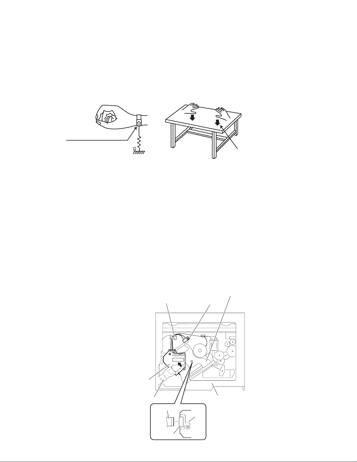
1.2 Preventing static electricity
Electrostatic discharge (ESD), which occurs when static electricity stored in the body, fabric, etc. is discharged, can destroy the laser
diode in the traverse unit (optical pickup). Take care to prevent this when performing repairs.
1.2.1 Grounding to prevent damage by static electricity
Static electricity in the work area can destroy the optical pickup (laser diode) in devices such as CD players.
Be careful to use proper grounding in the area where repairs are being performed.
(1) Ground the workbench
Ground the workbench by laying conductive material (such as a conductive sheet) or an iron plate over it before placing the
traverse unit (optical pickup) on it.
(2) Ground yourself
Use an anti-static wrist strap to release any static electricity built up in your body.
(caption)
Anti-static wrist strap
1M
Conductive material
(conductive sheet) or iron plate
(3) Handling the optical pickup
• In order to maintain quality during transport and before installation, both sides of the laser diode on the replacement optical
pickup are shorted. After replacement, return the shorted parts to their original condition.
(Refer to the text.)
• Do not use a tester to check the condition of the laser diode in the optical pickup. The tester's internal power source can easily
destroy the laser diode.
1.3 Handling the traverse unit (optical pickup)
(1) Do not subject the traverse unit (optical pickup) to strong shocks, as it is a sensitive, complex unit.
(2) Cut off the shorted part of the flexible cable using nippers, etc. after replacing the optical pickup. For specific details, refer to the
replacement procedure in the text. Remove the anti-static pin when replacing the traverse unit. Be careful not to take too long a
time when attaching it to the connector.
(3) Handle the flexible cable carefully as it may break when subjected to strong force.
(4) It is not possible to adjust the semi-fixed resistor that adjusts the laser power. Do not turn it.
1.4 Attention when traverse unit is decomposed
*Please refer to "Disassembly method" in the text for the CD pickup unit.
• Apply solder to the short land before the flexible wire is disconnected from the connector on the CD pickup unit.
(If the flexible wire is disconnected without applying solder, the CD pickup may be destroyed by static electricity.)
• In the assembly, be sure to remove solder from the short land after connecting the flexible wire.
Pickup
Wires
Push switch
Base board
Frame
Flexible wire
Connector
CD mechanism
assembly
Pickup
(No.MY003)1-3
Page 4
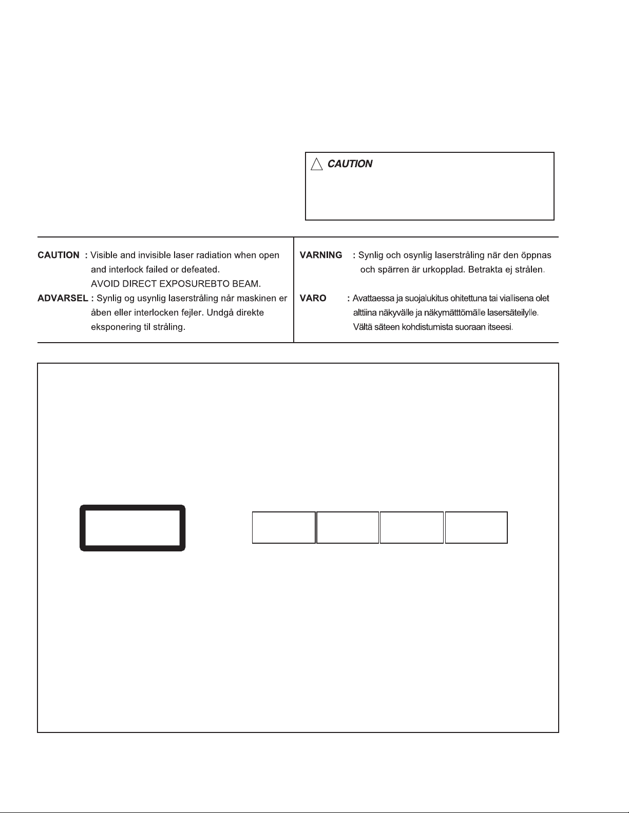
1.5 Important for laser products
!
1.CLASS 1 LASER PRODUCT
2.DANGER : Invisible laser radiation when open and inter
lock failed or defeated. Avoid direct exposure to beam.
3.CAUTION : There are no serviceable parts inside the
Laser Unit. Do not disassemble the Laser Unit. Replace
the complete Laser Unit if it malfunctions.
4.CAUTION : The CD,MD and DVD player uses invisible
laser radiation and is equipped with safety switches which
prevent emission of radiation when the drawer is open and
the safety interlocks have failed or are defeated. It is
dangerous to defeat the safety switches.
5.CAUTION : If safety switches malfunction, the laser is able
to function.
6.CAUTION : Use of controls, adjustments or performance of
procedures other than those specified here in may result in
hazardous radiation exposure.
Please use enough caution not to
see the beam directly or touch it
in case of an adjustment or operation
check.
REPRODUCTION AND POSITION OF LABELS
WARNING LABEL
CAUTION : Visible and Invisible
CLASS 1
LASER PRODUCT
laser radiation when open and
interlock failed or defeated.
AVOID DIRECT EXPOSURE TO
BEAM. (e)
ADVARSEL : Synlig og usynlig
laserstråling når maskinen er
åben eller interlocken fejeler.
Undgå direkte eksponering til
stråling. (d)
VARNING : Synlig och
osynling laserstrålning när
den öppnas och spärren är
urkopplad. Betrakta ej
strålen. (s)
VARO : Avattaessa ja suojalukitus
ohitettuna tai viallisena olet alttiina
näkyvälle ja näkymättömälle
lasersäteilylle. Vältä säteen
kohdistumista suoraan itseesi. (f)
1-4 (No.MY003)
Page 5

SECTION 2
SPECIFIC SERVICE INSTRUCTIONS
This service manual does not describe SPECIFIC SERVICE INSTRUCTIONS.
(No.MY003)1-5
Page 6
SECTION 3
A
DISASSEMBLY
3.1 CD mechanism assembly
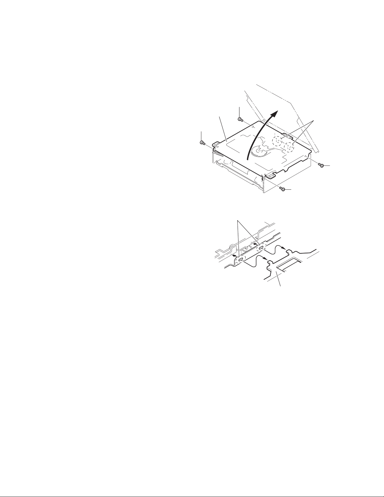
3.1.1 Removing the top cover
(See Figs.1 and 2)
(1) From the both side of the CD mechanism assembly, re-
move the four screws A attaching the top cover. (See
Fig.1.)
(2) Lift the front side of the top cover and move the top cover
backward to release the two joints a. (See Figs.1 and 2.)
Top cover
A
a
A
A
Fig.1
a
Top cover
Fig.2
1-6 (No.MY003)
Page 7

3.1.2 Removing the push switch
(See Figs.3)
(1) From the bottom side of the CD mechanism assembly, re-
move the screw B attaching the push switch.
(2) Take out the push switch from the CD mechanism assem-
bly.
Reference:
Remove the wires from soldered sections b of the push switch
as required.
3.1.3 Removing the base board
(See Figs.3 and 4)
Caution:
Solder the short land c before the flexible wire is disconnected
from the connector on the pickup. If the flexible wire is disconnected without applying solder, the pickup may be destroyed
by static electricity. (See Fig.3.)
(1) From the bottom side of the CD mechanism assembly, re-
move the screw C attaching the base board. (See Figs.3
and 4.)
(2) Solder the short land c on the pickup. (See Fig.3.)
(3) Disconnect the flexible wire from the connector on the pick-
up. (See Fig.3.)
(4) Remove the base board from the joints d of the frame in the
direction of the arrow. (See Figs.3 and 4.)
Reference:
Remove the wires from the soldered sections e on the base
board as required. (See Fig.3.)
Caution:
When reattaching the base board, be sure to remove solder
from the short land c after connecting the flexible wire. (See
Fig.3.)
e
C
Base board
Frame
Wires
B
b
d
Push switch
Flexible wire
Connector
Fig.3
Pickup
CD mechanism
assembly
Pickup
c
C
Base board
Flexible wire
Frame
d
Fig.4
(No.MY003)1-7
Page 8

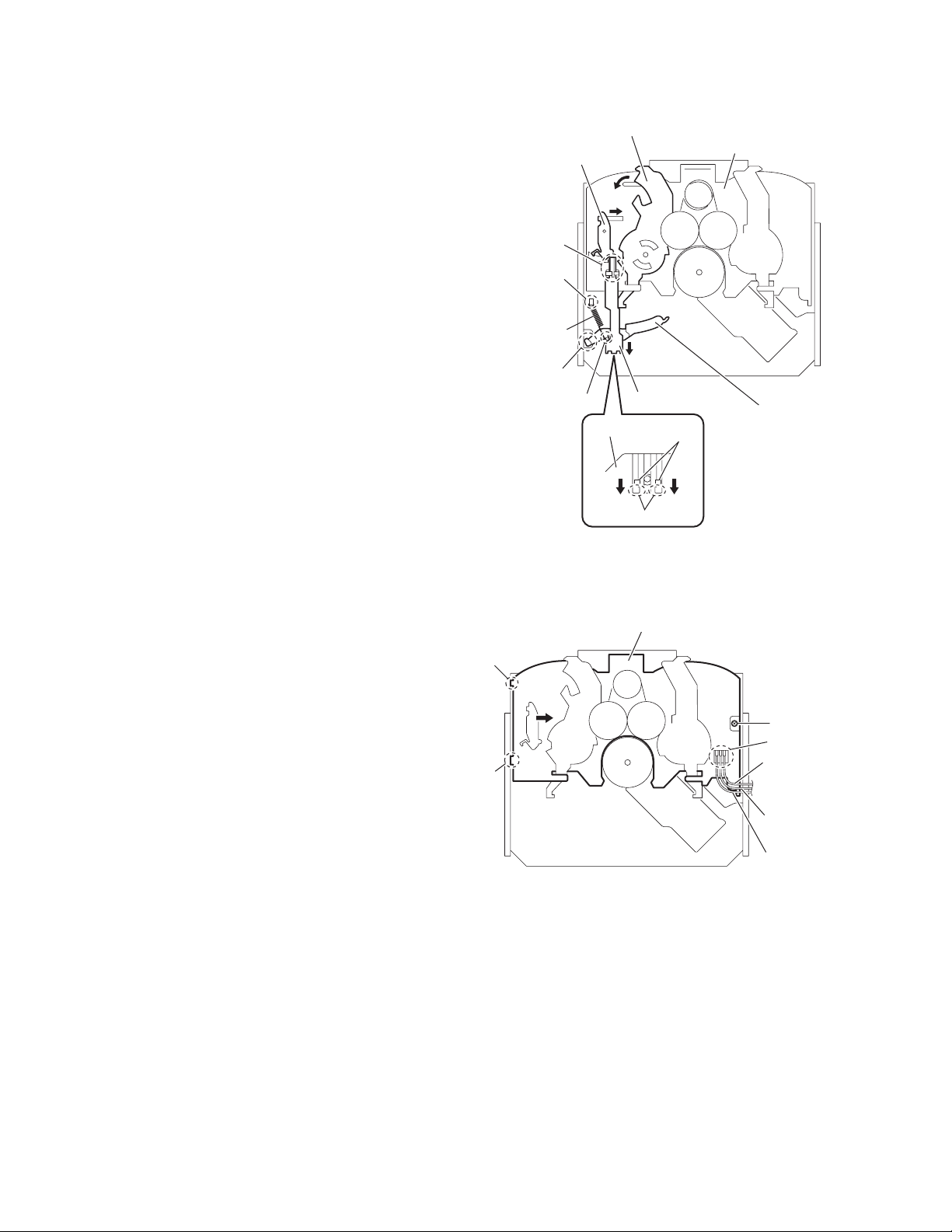
3.1.4 Removing the chassis unit
(See Figs.5 and 6)
• Remove the top cover and base board.
(1) From the top side of the CD mechanism assembly, remove
the front suspension springs and rear suspension springs
attaching the chassis unit to the frame. (See Fig.5.)
(2) Remove the chassis unit from the dampers on the frame in
an upward direction. (See Fig.6.)
Note:
• Pay attention to misuse and loss of each spring. (See Fig.5.)
• When reassembling, make sure that the three shafts on the
underside of the chassis unit are inserted to the dampers
certainly. (See Fig.6.)
Chassis unit
Front suspension spring
Front suspension spring
Frame
Rear suspension spring Rear suspension spring
Fig.5
Shaft
Damper F
Damper F
Chassis unit
Shaft
Damper R
Frame
Shaft
Fig.6
1-8 (No.MY003)
Page 9

3.1.5 Removing the clamper assembly
(See Figs.7 and 8)
• Remove the top cover.
Move the clamper assembly in the direction of the arrow to release the joints f from the chassis unit.
Chassis unit
f
Clamper assembly
Clamper assembly
Chassis unit
f
Fig.7
f
f
Fig.8
(No.MY003)1-9
Page 10

3.1.6 Removing the loading/feed motor assembly
(See Fig.9)
• Remove the top cover, base board and chassis unit.
From the bottom side of the chassis unit, remove the screw D
and take out the loading/feed motor assembly in the direction of
the arrow.
Reference:
Remove the wires from the soldered sections g of the loading/
feed motor assembly as required.
Loading/feed motor assembly
g
Chassis unit
Loading/feed
motor
assembly
D
Fig.9
1-10 (No.MY003)
Page 11

3.1.7 Removing the pickup
(See Figs.10 to 12)
• Remove the top cover, base board and chassis unit.
(1) From the bottom side of the chassis unit, remove the screw
E attaching the pu. shaft holder B and pull the pu. shaft out
of the pu. shaft holder A. (See Fig.10.)
(2) Remove the screw F attaching the pu. shaft holder A. (See
Fig.10.)
(3) Take out the pickup with pu. shaft holder A and feed screw
assembly from the chassis unit. (See Fig.11.)
(4) Remove the section h of the pu. shaft holder A in the direc-
tion of the arrow. (See Fig.11.)
(5) Remove the feed screw assembly from the section j of the
pickup in the direction of the arrow. (See Fig.11.)
(6) Remove the screw G attaching the feed screw holder to the
pickup. (See Fig.12.)
Reference:
Remove the feed nut spring from the feed screw holder
as required. (See Fig.12.)
(7) Release the claw k in the direction of the arrow to remove
the feed sub holder. (See Fig.12.)
Pickup
Feed screw assembly
Pu. shaft holder A
Fig.11
G
h
j
Feed screw
holder
3.1.8 Reattaching the pickup
(See Figs.10 to 13)
(1) Reattach the feed sub holder to the pickup. (See Fig.12.)
(2) Reattach the feed screw holder to the pickup using the
screw G. (See Fig.12.)
(3) Reattach the feed screw assembly and pu. shaft holder A
to the pickup as before. (See Fig.11.)
(4) Set the section m of the pickup to the rail of the chassis unit
at first and attach the pickup to the chassis unit with the
screw F as before. (See Figs.10 and 13.)
(5) Attach the pu. shaft to the pickup as before. (See Fig.10.)
(6) Attach the pu. shaft holder B to the chassis unit with the
screw E as before. (See Fig.10.)
Chassis unit
Pu. shaft holder A
Pu. shaft
F
Feed screw holder
Pickup
k
Feed sub holder
Pickup
Rail
Feed nut
spring
Fig.12
m
F
E
Pu. shaft holder B
Fig.10
Pickup
Chassis unit
Fig.13
(No.MY003)1-11
Page 12
3.1.9 Removing the trigger arm
(See Fig.14)
• Remove the top cover, base board, chassis unit and clamper
assembly.
(1) From the top side of the chassis unit, remove the trigger
arm spring from the sections (n, p).
(2) From the bottom side of the chassis unit, release the claws
q of the trigger arm base in the direction of the arrow to remove them from the sections r of the chassis unit to the
other side.
Note:
When releasing the claws q, take care not to break them.
(3) From the top side of the chassis unit, move the select arm
R and select lock arm in the direction of the arrow to remove the trigger arm base from the section s in the direction of the arrow.
(4) Remove the trigger arm from the section t.
Select lock arm
s
n
Trigger arm
spring
t
Select arm R
p
Trigger arm base
Chassis unit
r
Chassis unit
Trigger arm
q
3.1.10 Removing the top plate assembly
(See Fig.15)
• Remove the top cover, base board, chassis unit, clamper as-
sembly and trigger arm.
(1) Remove the screw H attaching the top plate assembly.
(2) Move the top plate assembly in the direction of the arrow to
release the joints (u, v).
Reference:
Remove the wires from the soldered sections w of the top plate
assembly as required.
Note:
When reassembling, solder the wires as before.
Fig.14
Top plate assembly
u
H
w
v
Fig.15
Wire(Red)
Wire(White)
Wire(Brown)
1-12 (No.MY003)
Page 13
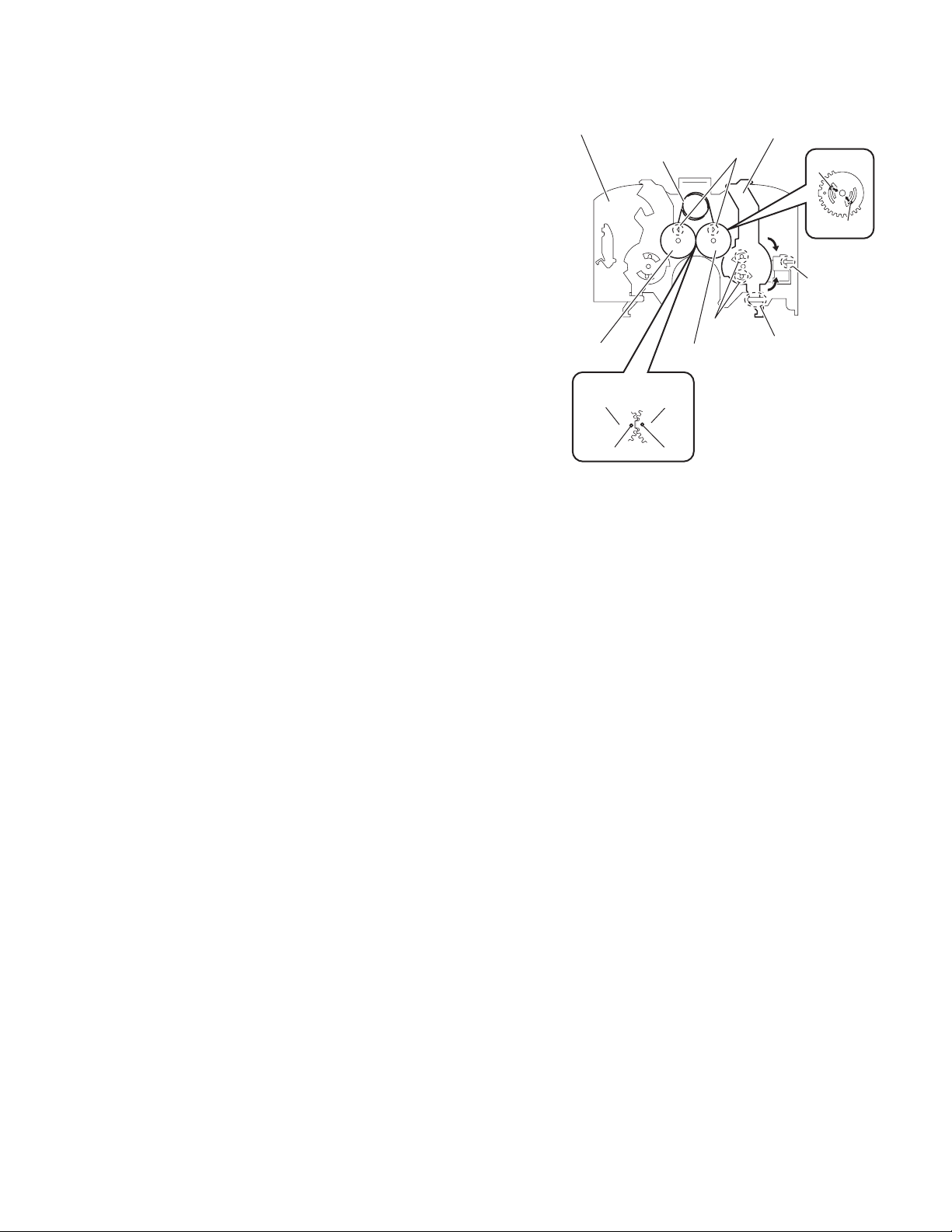
3.1.11 Removing the mode switch
(See Fig.16)
• Remove the top cover, base board, chassis unit, clamper as-
sembly, trigger arm and top plate assembly.
(1) From the top side of the top plate assembly, remove the
link gear spring from the sections x of the link gear L and
link gear R.
(2) Remove the link gear L in an upward direction while releas-
ing the claws y of the link gear L in the direction of the arrow.
(3) Move the mode switch in the direction of the arrow 1 to re-
move the sections z of the top plate assembly.
(4) Move the mode switch in the direction of the arrow 2 and
remove the mode switch from the sections (aa, ab).
Note:
When reattaching the link gear L, attach it after aligning the
hole ac of the link gear L to the hole ac of the link gear R.
Reference:
When reassembling, reverse the above removing procedure.
Top plate assembly
Link gear spring
Link gear R
Link
gear R
ac ac
Link gear L
Link
gear L
aa
Fig.16
Mode switch
x
1
2
z
y
y
ab
(No.MY003)1-13
Page 14
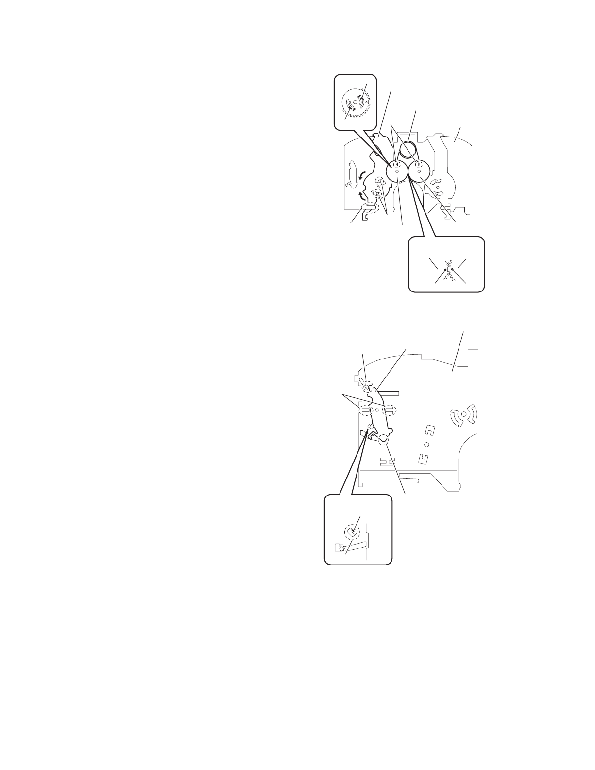
3.1.12 Removing the select arm R and select lock arm
(See Figs.17 and 18)
• Remove the top cover, base board, chassis unit, clamper as-
sembly, trigger arm and top plate assembly.
(1) From the top side of the top plate assembly, remove the
link gear spring from the sections ad of the link gear L and
link gear R. (See Fig.17.)
(2) Remove the link gear R in an upward direction while releas-
ing the claws ae of the link gear R in the direction of the arrow. (See Fig.17.)
(3) Move the select arm R in the direction of the arrow 1 to re-
move the sections af of the top plate assembly. (See
Fig.17.)
(4) Move the select arm R in the direction of the arrow 2 and
remove the select arm R from the sections ag. (See
Fig.17.)
(5) From the bottom side of the top plate assembly, remove
the select lock arm spring from the section ah. (See
Fig.18.)
(6) From the top side of the top plate assembly, remove the
section aj of the select lock arm from the top plate assembly at first and remove the sections (ak, am) of the select
lock arm from the top plate assembly. (See Fig.18.)
Note:
• When removing the select lock arm spring, be careful not to
lose it. (See Fig 18.)
• When reattaching the link gear R, attach it after aligning the
hole an of the link gear R to the hole an of the link gear L.
(See Fig.17.)
Reference:
When reassembling, reverse the above removing procedure.
ae
2
af
ae
Select arm R
ad
1
ag
Link gear R
Select lock arm
aj
Link gear spring
Top plate assembly
Link gear L
Link
gear R
an an
Fig.17
Top plate assembly
Link
gear L
ak
Select lock
arm spring
ah
am
Fig.18
1-14 (No.MY003)
Page 15

3.1.13 Removing the loading roller assembly
(See Figs.19 to 21)
• Remove the top cover, base board, chassis unit, clamper as-
sembly and top plate assembly.
(1) From the left side of the chassis unit, remove the screw J
attaching the lock arm assembly. (See Fig.19.)
(2) Remove the projection ap of the lock arm assembly from
the joint aq while opening the cam plate R in the direction
of the arrow. (See Fig.19.)
(3) Remove the lock arm assembly from the projection ar of
the chassis unit. (See Fig.19.)
(4) Remove the projection as of the lock arm assembly from
the joint at of the cam plate L assembly. (See Fig.19.)
(5) From the right side of the lock arm assembly, remove the
loading roller spring L from the section au. (See Fig.20.)
(6) From the top side of the lock arm assembly, remove the
loading roller spring R in the direction of the arrow and remove the loading roller assembly. (See Fig.20.)
(7) Remove the roller guide R, HL washer and roller guide L
from the both ends of the loading roller assembly. (See
Fig.21.)
J
Lock arm assembly
ap
aq
Cam plate R
Fig.19
Chassis unit
Cam plate L assembly
ar
at
as
Loading roller assembly
Lock arm assembly
Loading roller
spring L
au
Roller guide L Roller guide R
Loading roller assembly
Loading roller spring R
Fig.20
HL washer
Fig.21
(No.MY003)1-15
Page 16

3.1.14 Removing the loading gear 1, loading gear 2, loading gear 3 and feed gear 1
(See Fig.22)
• Remove the top cover, base board and chassis unit.
(1) From the bottom side of the chassis unit, pull out the load-
ing gear 1.
(2) Take out the loading gear 2.
(3) Pull out the loading gear 3.
(4) Pull out the feed gear 1.
3.1.15 Removing the loading gear 4, loading gear 5 and
loading gear 6
(See Fig.22)
• Remove the top cover, base board and chassis unit.
(1) From the bottom side of the chassis unit, remove the screw
K attaching the loading gear bracket.
(2) Take out the loading gear bracket and remove the loading
gear 5 and loading gear 6 from the loading gear bracket.
(3) Pull out the loading gear 4.
3.1.16 Removing the change gear 2, change gear 3A and
change gear 3B
(See Figs.22 and 23)
• Remove the top cover, base board and chassis unit.
(1) From the bottom side of the chassis unit, pull out the load-
ing gear 1. (See Fig.22.)
(2) Pull out the change gear 2. (See Fig.22.)
(3) Pull out the change arm. (See Fig.22.)
(4) Move the change gear plate rivet assembly in the direction
of the arrow 2 to remove the section av of the change gear
plate rivet assembly from the chassis unit while moving the
change lock lever in the direction of the arrow 1. (See
Fig.23.)
(5) Pull out the change gear 3A and change gear 3B from the
change gear plate rivet assembly. (See Fig.23.)
Loading gear bracket
Loading gear 3
Feed gear 2
Feed gear 1
Change gear plate rivet assembly
Chassis unit
Fig.22
Loading gear 6
Loading gear
bracket
Change arm
Change gear plate
rivet assembly
Loading
gear 5
K
Loading gear 4
Loading gear 1
Loading gear 2
3.1.17 Removing the cam plate L assembly
(See Fig.24)
• Remove the top cover, base board, chassis unit, clamper as-
sembly, top plate assembly and loading roller assembly.
(1) From the left side of the chassis unit, slide the cam plate L
assembly in the direction of the arrow.
(2) Remove the cam plate L assembly from the slots aw of the
chassis unit.
Change gear 3B
Change lock lever
Chassis unit
2
1
Chassis unit
Fig.23
aw
Cam plate L assembly
Change
gear 3A
Change gear 3B
Change gear 3A
av
aw
1-16 (No.MY003)
Fig.24
Page 17

3.1.18 Removing the cam plate R
(See Fig.25)
• Remove the top cover, base board, chassis unit, clamper as-
sembly, top plate assembly and loading roller assembly.
From the right side of the chassis unit, remove the cam plate R
from the slots ax of the chassis unit.
Reference:
When a slide hook rivet assembly and a trigger rack spring
have come off from the chassis unit, attach them before at-
taching the cam plate R.
3.1.19 Removing the trigger rack plate
(See Figs.25 and 26)
• Remove the top cover, base board, chassis unit, clamper as-
sembly, top plate assembly, loading roller assembly and cam
plate R.
(1) Remove the slide hook rivet assembly and trigger rack
spring from the chassis unit. (See Fig.25.)
(2) From the bottom side of the chassis unit, pull out the load-
ing gear 1. (See Fig.26.)
(3) Remove the trigger control spring from the sections (ay,
az). (See Fig.26.)
(4) Take out the trigger rack plate from the chassis unit. (See
Fig.26.)
Reference:
When attaching the trigger rack plate, insert the projection a'
of the chassis unit in the slot b' on the bottom side of the trigger
rack plate as before. (See Fig.26.)
Chassis unit
ax
Cam plate R
b'
Trigger rack spring
Slide hook rivet assembly
ax
Fig.25
Trigger control spring
az
a'
Trigger
rack plate
Trigger rack plate
Loading gear 1
ay
Chassis unit
Fig.26
(No.MY003)1-17
Page 18

3.1.20 Removing the spindle motor assembly
(See Figs.27 and 28)
• Remove the top cover, base board, chassis unit and clamper
assembly.
(1) From the top side of the chassis unit, turn the turn table
from side to side and remove the two screws M attaching
the spindle motor assembly through the hole of the turn table. (See Fig.27.)
(2) From the bottom side of the chassis unit, turn the change
gear 2 in the direction of the arrow 2 while pulling the trigger
arm in the direction of the arrow 1 and let the pickup move
in the direction of the arrow 3. (See Fig.28.)
(3) Slide the spindle motor assembly in the direction of the ar-
row and take out it in an upward direction from the chassis
unit. (See Fig.28.)
Reference:
Remove the wires from the soldered sections c' on the base
board and remove them from the sections (d', e') on the chassis unit as required.
Chassis unit
Wire(black)
Wire(red)
M
Fig.27
Spindle motor assembly
d'
Turn table
e'
Change gear 2
c'
Base board
3
Pickup
2
1
Trigger arm
Chassis unit
Fig.28
1-18 (No.MY003)
Page 19

SECTION 4
ADJUSTMENT
This service manual does not describe ADJUSTMENT.
SECTION 5
TROUBLESHOOTING
This service manual does not describe TROUBLESHOOTING.
(No.MY003)1-19
Page 20

Victor Company of Japan, Limited
Mobile Entertainment Business Group Mobile Entertainment Category 10-1,1chome,Ohwatari-machi,Maebashi-city,371-8543,Japan
(No.MY003)
Printed in Japan
VPT
 Loading...