

Page 1
CD RECEIVER KD-G116/KD-G115
KD-G116/KD-G115
For canceling the display demonstration, see page 7.
ENGLISH
For installation and connections, refer to the separate manual.
INSTRUCTIONS
GET0252-001A
[U/UH]
Page 2
Thank you for purchasing a JVC product.
Please read all instructions carefully before operation, to ensure your complete understanding and to
obtain the best possible performance from the unit.
ENGLISH
IMPORTANT FOR LASER PRODUCTS
1. CLASS 1 LASER PRODUCT
2. CAUTION : Do not open the top cover. There are no user serviceable parts inside the unit; leave
all servicing to qualified service personnel.
3. CAUTION : Visible and invisible laser radiation when open and interlock failed or defeated.
Avoid direct exposure to beam.
4. REPRODUCTION OF LABEL: CAUTION LABEL, PLACED OUTSIDE THE UNIT.
Warning:
If you need to operate the receiver while
driving, be sure to look ahead carefully or
you may be involved in a traffic accident.
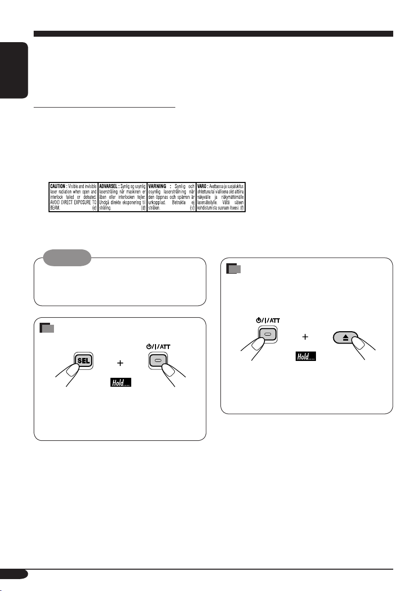
How to forcibly eject a disc
If a disc cannot be recognized by the
receiver or cannot be ejected, ejects the disc
as follows.
How to reset your unit
• This will reset the microcomputer. Your
preset adjustments will also be erased.
• If a disc is loaded, it will eject. Be careful
not to drop the disc.
2
• If this does not work, try to reset your
receiver.
• Be careful not to drop the disc when it
ejects.
Page 3

Contents
How to reset your unit ........................... 2
How to forcibly eject a disc................... 2
How to read this manual........................ 4
How to use the MODE button ............... 4
Control panel
— KD-G116/KD-G115 ............... 5
Parts identification................................. 5
Getting started....................... 6
Basic operations ........................... 6
Canceling the display demonstrations ... 7
Setting the clock .................................... 7
Radio operations ................... 8
Listening to the radio........................... 8
Storing stations in memory.................... 9
Listening to a preset station ................... 9
Disc operations ...................... 10
Playing a disc ..................................... 10
Selecting the playback modes................ 11
Sound adjustments ................ 12
Selecting preset sound modes
(C-EQ: custom equalizer) .................. 12
Adjusting the sound ............................... 13
ENGLISH
General settings — PSM ......... 14
Basic procedure ..................................... 14
Detaching the control panel.... 15
Maintenance .......................... 16
More about this receiver ........ 17
Troubleshooting ..................... 18
Specifications ......................... 19
*For safety....
• Do not raise the volume level too much, as
this will block outside sounds, making driving
dangerous.
• Stop the car before performing any
complicated operations.
*Temperature inside the car....
If you have parked the car for a long time in
hot or cold weather, wait until the temperature
in the car becomes normal before operating the
unit.
3
Page 4
How to read this manual
The following methods are used to made the
explanations simple and easy-to-understand:
• Some related tips and notes are explained in
ENGLISH
“More about this receiver” (see page 17).
• Button operations are mainly explained with
the illustrations as follows:
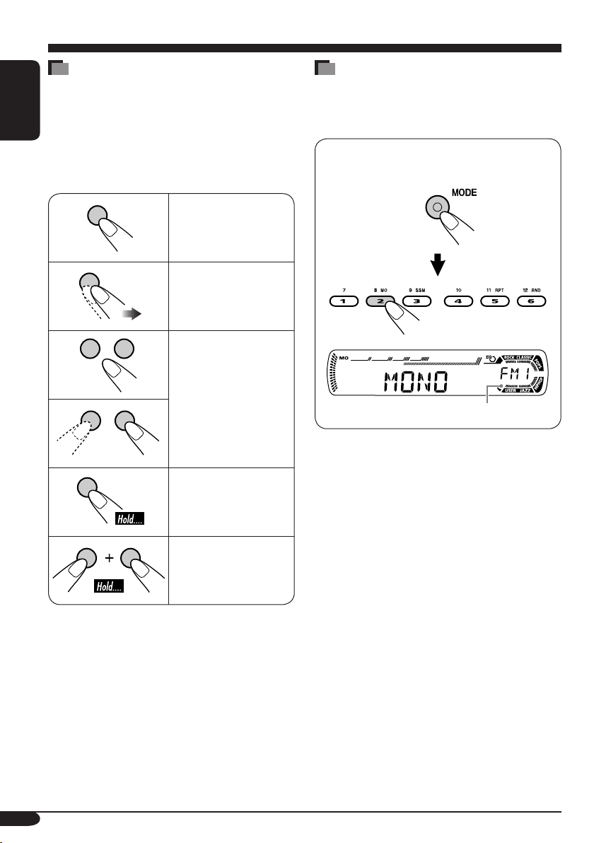
Press briefly.
Press repeatedly.
Press either one.
Press and hold until
your desired response
begins.
How to use the MODE button
If you press MODE, the receiver goes into
functions mode, then the number buttons work
as different function buttons.
Ex.: When number button 2 works as
MO (monaural) button.
Time countdown indicator
To use these buttons for original functions
again after pressing MODE, wait for
5 seconds without pressing any of these buttons
until the functions mode is cleared.
• Pressing MODE again also clears the
functions mode.
Press and hold both
buttons at the same
time.
4
Page 5
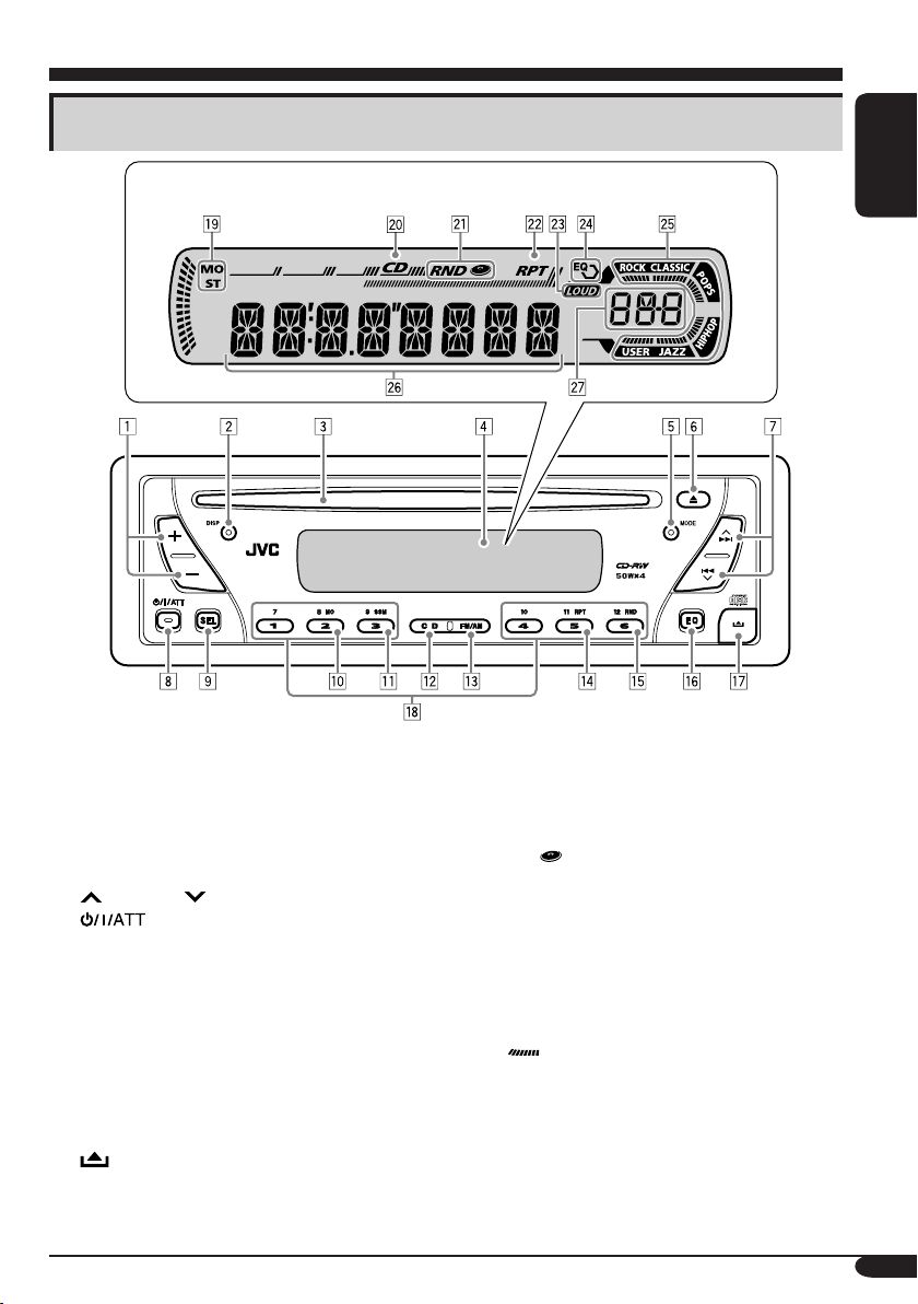
Control panel — KD-G116/KD-G115
Parts identification
Display window
1 +/– buttons
2 DISP (display) button
3 Loading slot
4 Display window
5 MODE button
6 0 (eject) button
7
¢/4 buttons
8
9 SEL (select) button
p MO (monaural) button
q SSM (Strong-station Sequential Memory)
w CD button
e FM/AM button
r RPT (repeat) button
t RND (random) button
y EQ (equalizer) button
u
i Number buttons
(standby/on/attenuator) button
button
(control panel release) button
Display window
o Tuner reception indicators
MO (monaural), ST (stereo)
; CD indicator
a RND
s RPT (repeat) indicator
d LOUD (loudness) indicator
f EQ (equalizer) indicator
g Sound mode (C-EQ: custom equalizer)
indicators
ROCK, CLASSIC, POPS, HIP HOP, JAZZ,
USER
•
h Main display
j Source display
Volume level indicator
(disc random) indicator
also works as the time countdown
indicator.
ENGLISH
5
Page 6
Getting started
ENGLISH
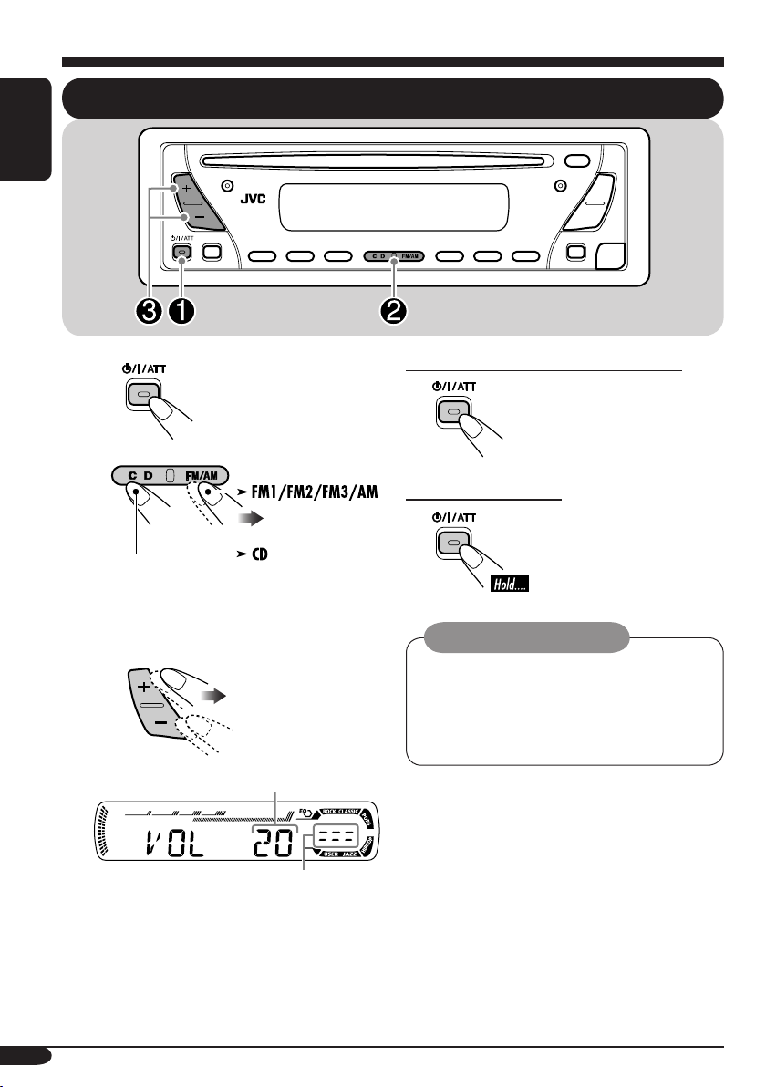
Basic operations
~
Ÿ
You cannot select “CD” as the playback
source if there is no disc in the loading
slot.
!
Volume level appears.
Volume level indicator
To drop the volume in a moment (ATT)
To restore the sound, press
it again.
To turn off the power
Caution on volume setting:
Discs produce very little noise compared
with other sources. Lower the volume
before playing a disc to avoid damaging
the speakers by the sudden increase of the
output level.
⁄ Adjust the sound as you want.
(See pages 12 and 13.)
6
Page 7
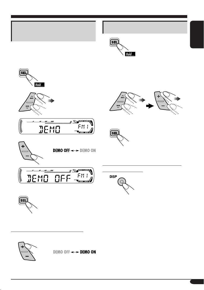
Canceling the display
demonstrations
If no operations are done for about 20 seconds,
display demonstration starts.
[Initial: DEMO ON]—see page 14.
1
2
3
Setting the clock
1
2
Set the hour and minute.
1 Select “CLOCK H” (hour), then
adjust the hour.
2 Select “CLOCK M” (minute),
then adjust the minute.
3 Finish the procedure.
To check the current clock time when the
receiver is turned off
ENGLISH
Finish the procedure.
4
To activate the display demonstration
In step 3 above...
7
Page 8
Radio operations
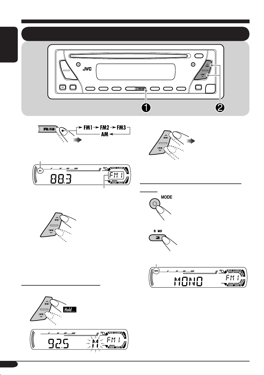
Listening to the radio
ENGLISH
~
Lights up when receiving an FM stereo
broadcast with sufficient signal strength.
Selected band appears.
Ÿ Start searching for a station.
2 Select the desired station frequencies.
When an FM stereo broadcast is hard to
receive
1
When a station is received, searching
stops.
To stop searching, press the same
button again.
To tune in to a station manually
In step Ÿ above...
1
8
2
Lights up when monaural mode is activated.
Reception improves, but stereo effect will
be lost.
To restore the stereo effect, repeat the same
procedure so that the MO indicator goes off.
Page 9
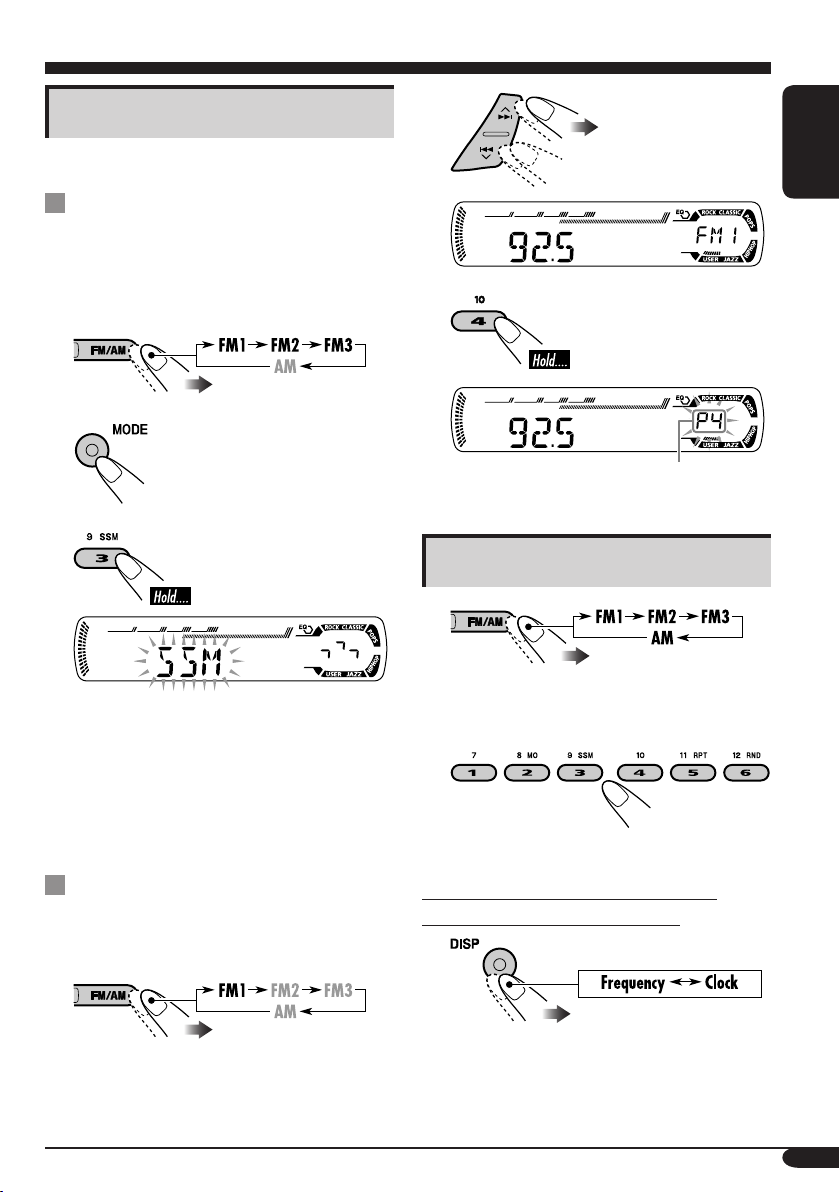
Storing stations in memory
You can preset six stations for each band.
FM station automatic presetting —
SSM (Strong-station Sequential
Memory)
Select the FM band (FM1 – FM3)
1
you want to store into.
2
3
2
ENGLISH
3
Preset number flashes for a while.
Listening to a preset station
1
“SSM” flashes, then disappears when
automatic presetting is over.
Local FM stations with the strongest signals are
searched and stored automatically in the FM
band.
Manual presetting
Ex.: Storing FM station of 92.5 MHz into the
preset number 4 of the FM1 band.
1
2 Select the preset station (1 – 6) you
want.
To check the current clock time while
listening to an FM or AM station
9
Page 10
Disc operations
ENGLISH
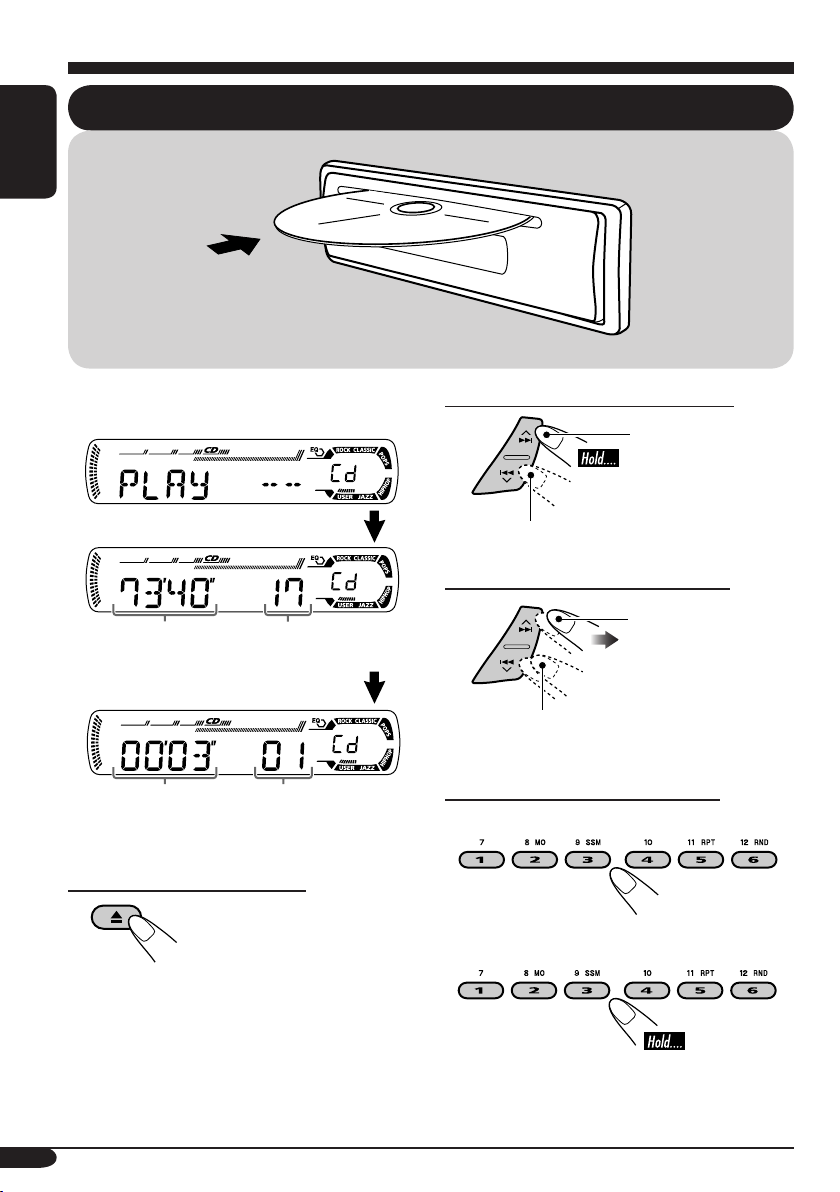
Playing a disc
All tracks will be played repeatedly until you
stop playback.
Total playing time of
the inserted disc
Elapsed playing
time
Total track number
of the inserted disc
Current track
number
To stop play and eject the disc
To fast-forward or reverse the track
Fast-forwards.
Reverses.
To go to the next or previous tracks
To the following
tracks.
To the beginning of the current track, then
the previous tracks.
To go to a particular track directly
To select a number from 01 – 06:
To select a number from 07 – 12:
10
Page 11
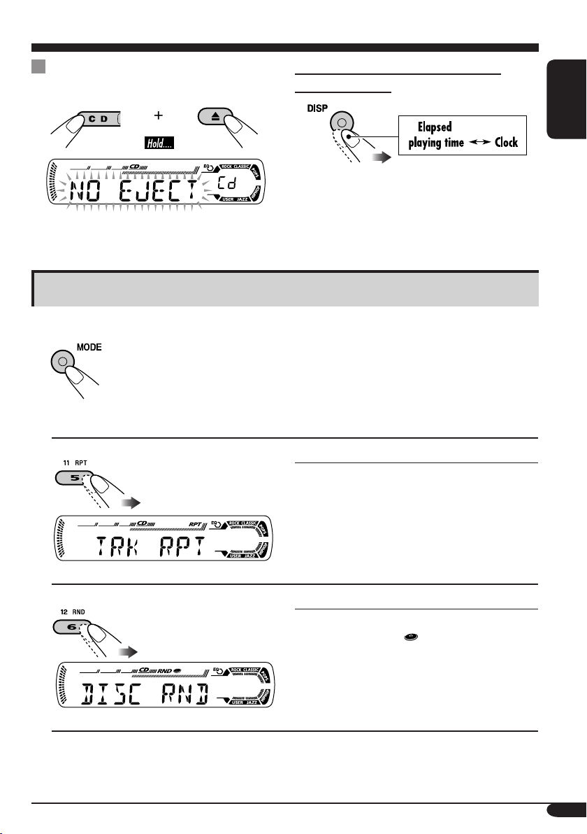
Prohibiting disc ejection
You can lock a disc in the loading slot.
To cancel the prohibition, repeat the same
procedure.
To check the current clock time while
listening to a disc
Selecting the playback modes
You can use only one of the following playback modes at a time.
1
2 Select your desired playback mode.
ENGLISH
Repeat play
Ex.: When “TRK RPT” is selected
Random play
Ex.: When “DISC RND” is selected
Mode Plays repeatedly
TRK RPT: The current track.
• RPT lights up.
RPT OFF: Cancels repeat play.
Mode Plays at random
DISC RND: All tracks of the current disc.
• RND
RND OFF: Cancels random play.
lights up.
11
Page 12
Sound adjustments
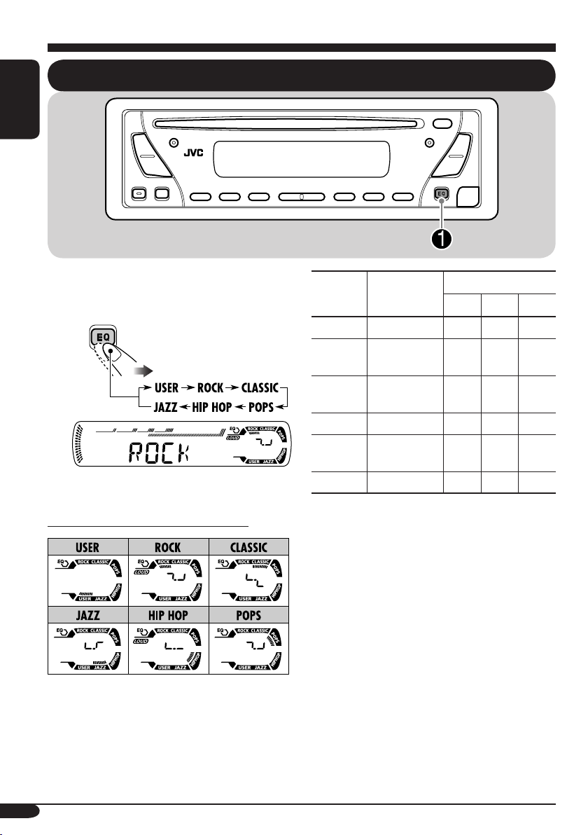
Selecting preset sound modes (C-EQ: custom equalizer)
ENGLISH
You can select a preset sound mode suitable to
the music genre.
~
Ex.: When “ROCK” is selected
Indication pattern for each sound mode:
Indication For:
USER (Flat sound) 00 00 OFF
ROCK Rock or disco
music
CLASSIC Classical
music
POPS Light music +04 +01 OFF
HIP HOP Funk or rap
music
JAZZ Jazz music +02 +03 OFF
1
*
BAS: Bass
2
*
TRE: Treble
3
*
LOUD: Loudness
1
TRE
*
2
LOUD
*
BAS
+03 +01 ON
+01 –02 OFF
+02 00 ON
Preset values
3
*
12
Page 13
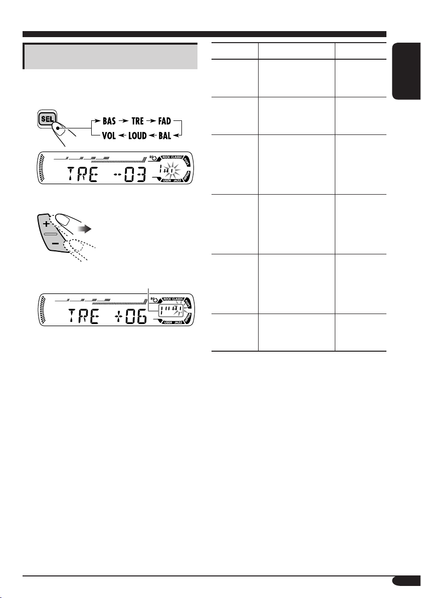
Adjusting the sound
You can adjust the sound characteristics to your
preference.
1
Ex.: When “TRE” is selected
2
Indication pattern changes
as you adjust the level.
Indication To do: Range
BAS*1
(bass)
TRE*
(treble)
FAD*
(fader)
BAL
(balance)
LOUD*
(loudness)
VOL*3
(volume)
Adjust the bass. –06 (min.)
1
Adjust the treble. –06 (min.)
2
Adjust the front
and rear speaker
balance.
Adjust the left
and right speaker
balance.
1
Boost low and
high frequencies
to produce a wellbalanced sound at
low volume level.
Adjust the
volume.
to
+06 (max.)
to
+06 (max.)
R06 (Rear
only)
to
F06 (Front
only)
L06 (Left
only)
to
R06 (Right
only)
LOUD ON
LOUD OFF
00 (min.) to
30 or 50
(max.)*
ENGLISH
J
4
*1 When you adjust the bass, treble, or
loudness, the adjustment you have made is
stored for the currently selected sound mode
(C-EQ) including “USER.”
2
*
If you are using a two-speaker system, set
the fader level to “00.”
3
*
Normally the +/– buttons work as the volume
control. So you do not have to select “VOL”
to adjust the volume level.
4
*
Depending on the amplifier gain control
setting. (See page 14 for details.)
13
Page 14

General settings — PSM
Basic procedure
3 Adjust the PSM item selected.
You can change PSM (Preferred Setting Mode)
items listed in the table that follows.
ENGLISH
1
4 Repeat steps 2 and 3 to adjust the
other PSM items if necessary.
Select a PSM item.
2
Ex.: When you select “AMP GAIN”
Indications Selectable settings, [reference page]
5 Finish the procedure.
DEMO
Display demonstration
CLOCK H
Hour adjustment
CLOCK M
Minute adjustment
AMP GAIN
Amplifier gain control
14
DEMO ON: [Initial]; Display demonstration will be activated
automatically if no operation is done for about
20 seconds, [7].
DEMO OFF: Cancels.
1 – 12, [7]
[Initial: 1 (1:00)]
00 – 59, [7]
[Initial: 00 (1:00)]
You can change the maximum volume level of this receiver.
LOW PWR: VOL 00 – VOL 30 (Select this if the maximum power
of the speaker is less than 50 W to prevent them from
damaging the speaker.)
HIGH PWR: [Initial]; VOL 00 – VOL 50
Page 15
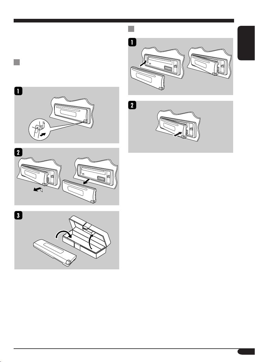
Detaching the control panel
When detaching or attaching the control panel,
be careful not to damage the connectors on
the back of the control panel and on the panel
holder.
Detaching the control panel
Before detaching the control panel, be sure to
turn off the power.
Attaching the control panel
ENGLISH
15
Page 16
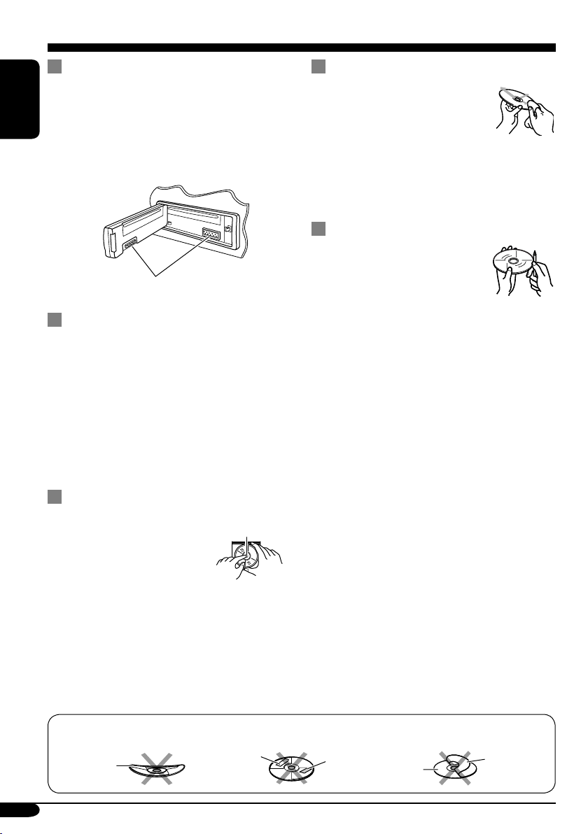
Maintenance
How to clean the connectors
Frequent detachment will deteriorate the
connectors.
To minimize this possibility, periodically wipe
ENGLISH
the connectors with a cotton swab or cloth
moistened with alcohol, being careful not to
damage the connectors.
Connector
Moisture condensation
Moisture may condense on the lens inside the
CD player in the following cases:
• After starting the heater in the car.
• If it becomes very humid inside the car.
Should this occur, the CD player may
malfunction. In this case, eject the disc and
leave the receiver turned on for a few hours
until the moisture evaporates.
To keep discs clean
A dirty disc may not play correctly.
If a disc does become dirty, wipe
it with a soft cloth in a straight line
from center to edge.
• Do not use any solvent (for
example, conventional record cleaner, spray,
thinner, benzine, etc.) to clean discs.
To play new discs
New discs may have some rough
spots around the inner and outer
edges. If such a disc is used, this
receiver may reject the disc.
To remove these rough spots, rub the edges
with a pencil or ball-point pen, etc.
How to handle discs
When removing a disc from
its case, press down the center
holder of the case and lift the
disc out, holding it by the
edges.
• Always hold the disc by the edges. Do not
touch its recording surface.
When storing a disc into its case, gently insert
the disc around the center holder (with the
printed surface facing up).
• Make sure to store discs into the cases after
use.
Do not use the following discs:
Warped
disc
16
Center holder
Sticker
Sticker
residue
Disc
Stick-on
label
Page 17

More about this receiver
Basic operations
Turning off the power
• If you turn off the power while listening to a
disc, disc play will start from where playback
has been stopped previously, next time you
turn on the power.
Tuner operations
Storing stations in memory
• During SSM search...
– All previously stored stations are erased and
stations are stored newly.
– Received stations are preset in No. 1 (lowest
frequency) to No. 6 (highest frequency).
– When SSM is over, the station stored in
No. 1 will be automatically tuned in.
• When storing a station manually, a previously
preset station is erased when a new station is
stored in the same preset number.
Disc operations
General
• This receiver has been designed to reproduce
CDs, and CD-Rs (Recordable)/ CD-RWs
(Rewritable) in audio CD (CD-DA) format.
• When a disc has been loaded, selecting “CD”
for the playback source starts disc play.
Inserting a disc
• When a disc is inserted upside down, the disc
automatically ejects.
• Do not insert 8 cm discs (single CD) and
unusual shape discs (heart, flower, etc.) into
the loading slot.
• Some CD-Rs or CD-RWs may not play
back on this receiver because of their disc
characteristics, and for the following causes:
– Discs are dirty or scratched.
– Moisture condensation occurs on the lens
inside the receiver.
– The pickup lens inside the receiver is dirty.
– CD-R or CD-RW on which the files are
written with “Packet Write” method.
– There are improper recording conditions
(missing data, etc.) or media conditions
(stain, scratch, warp, etc.).
• CD-RWs may require a longer readout time
since the reflectance of CD-RWs is lower
than that of regular CDs.
• Do not use the following CD-Rs or
CD-RWs:
– Discs with stickers, labels, or protective seal
stuck to the surface.
– Discs on which labels can be directly
printed by an ink jet printer.
Using these discs under high temperatures
or high humidity may cause malfunctions or
damage to discs.
Changing the source
• If you change the source, playback also stops
(without ejecting the disc).
Next time you select “CD” for the playback
source, disc play starts from where it has been
stopped previously.
Ejecting a disc
• If the ejected disc is not removed within
15 seconds, the disc is automatically inserted
again into the loading slot to prevent it from
dust. (Disc will not play this time.)
ENGLISH
Playing a CD-R or CD-RW
• Use only “finalized” CD-Rs or CD-RWs.
• This receiver can play back multi-session
discs; however, unclosed sessions will be
skipped while playing.
General settings—PSM
• If you change the “AMP GAIN” setting from
“HIGH PWR” to “LOW PWR” while the
volume level is set higher than “VOL 30,” the
receiver automatically changes the volume
level to “VOL 30.”
17
Page 18
Troubleshooting
What appears to be trouble is not always serious. Check the following points before calling a service
center.
ENGLISH
• Sound cannot be heard
General
• The receiver does not
• SSM automatic presetting
• Static noise while listening
FM/AM
• Disc automatically ejects. Disc is inserted upside
• CD-R/CD-RW cannot be
• Tracks on the CD-R/
• Disc can be neither played
Symptoms Causes Remedies
from the speakers.
work at all.
does not work.
to the radio.
played back.
CD-RW cannot be
skipped.
back nor ejected.
The volume level is set to
the minimum level.
Connections are incorrect. Check the cords and
The built-in microcomputer
may have functioned
incorrectly due to noise, etc.
Signals are too weak. Store stations manually.
The antenna is not connected
firmly.
down.
CD-R/CD-RW is not
finalized.
Disc is locked. Unlock the disc (see page
Adjust it to the optimum
level.
connections.
Reset the receiver (see page
2).
Connect the antenna firmly.
Insert the disc correctly.
• Insert a finalized CD-R/
CD-RW.
• Finalize the CD-R/
CD-RW with the
component which you
used for recording.
11).
18
Disc playback
• Disc sound is sometimes
interrupted.
• “NO DISC” appears on the
display.
The CD player may have
functioned incorrectly.
You are driving on rough
roads.
Disc is scratched. Change the disc.
Connections are incorrect. Check the cords and
No disc is in the loading
slot.
Disc is inserted incorrectly. Insert the disc correctly.
Eject the disc forcibly (see
page 2).
Stop playback while driving
on rough roads.
connections.
Insert a disc into the loading
slot.
Page 19

Specifications
AUDIO AMPLIFIER SECTION
Maximum Power Output:
Front: 50 W per channel
Rear: 50 W per channel
Continuous Power Output (RMS):
Front: 19 W per channel into 4 Ω, 40 Hz
to 20 000 Hz at no more than 0.8%
total harmonic distortion.
Rear: 19 W per channel into 4 Ω, 40 Hz
to 20 000 Hz at no more than 0.8%
total harmonic distortion.
Load Impedance: 4 Ω (4 Ω to 8 Ω allowance)
Tone Control Range:
Bass: ±10 dB at 100 Hz
Treble: ±10 dB at 10 kHz
Frequency Response: 40 Hz to 20 000 Hz
Signal-to-Noise Ratio: 70 dB
Line-Out Level/Impedance:
2.0 V/20 kΩ load (full scale)
Output Impedance: 1 kΩ
TUNER SECTION
Frequency Range:
FM: 87.5 MHz to 108.0 MHz
AM: 531 kHz to 1 602 kHz
[FM Tuner]
Usable Sensitivity: 11.3 dBf (1.0 µV/75 Ω)
50 dB Quieting Sensitivity:
16.3 dBf (1.8 µV/75 Ω)
Alternate Channel Selectivity (400 kHz): 65 dB
Frequency Response: 40 Hz to 15 000 Hz
Stereo Separation: 35 dB
Capture Ratio: 1.5 dB
CD PLAYER SECTION
Type: Compact disc player
Signal Detection System: Non-contact optical
pickup (semiconductor laser)
Number of channels: 2 channels (stereo)
Frequency Response: 5 Hz to 20 000 Hz
Dynamic Range: 96 dB
Signal-to-Noise Ratio: 98 dB
Wow and Flutter: Less than measurable limit
GENERAL
Power Requirement:
Operating Voltage:
DC 14.4 V (11 V to 16 V allowance)
Grounding System: Negative ground
Allowable Operating Temperature:
0°C to +40°C
Dimensions (W × H × D):
Installation Size (approx.):
182 mm × 52 mm × 150 mm
Panel Size (approx.):
188 mm × 58 mm × 11 mm
Mass (approx.):
1.3 kg (excluding accessories)
Design and specifications are subject to change
without notice.
ENGLISH
[AM Tuner]
Sensitivity: 20 µV
Selectivity: 35 dB
Having TROUBLE with operation?
Please reset your unit
Refer to page of How to reset your unit
19
Page 20

EN, TH
© 2004 Victor Company of Japan, Limited
1004DTSMDTJEIN
Page 21

KD-G116/KD-G115
Installation/Connection Manual
°“√µ‘¥µ—Èß/§ŸË¡◊Õ°“√µ‘¥µ—Èß
GET0252-004A
[U/UH]
ENGLISH
This receiver is designed to operate on 12 V DC, NEGATIVE ground electrical systems. If
your vehicle does not have this system, a voltage inverter is required, which can be purchased
at JVC car audio dealers.
Parts list for installation and connection
The following parts are provided for this receiver.
After checking them, please set them correctly.
A / B
Hard case/Control panel
≈—ß∫√√®ÿ/ÀπÈ“ª—¥
F
Washer (ø5)
ª√–‡°Áπ«ß·À«π (ø5)
G
Lock nut (M5)
πÕµ≈ÁÕ§ (M5)
C
Sleeve
ª≈Õ°ÀÿÈ¡
H
Mounting bolt (M5 x 20 mm)
≈—°µ‘¥ (M5 x 20 ¡‘≈≈‘‡¡µ√)
INSTALLATION (IN-DASH MOUNTING)
The following illustration shows a typical installation. If you have any questions or require
information regarding installation kits, consult your JVC car audio dealer or a company supplying
kits.
• If you are not sure how to install this receiver correctly, have it installed by a qualified
technician.
1004DTSMDTJEIN
EN, TH
‰∑¬
™ÿ¥ª√–°Õ∫π’ȉ¥È√—∫°“√ÕÕ°·∫∫¡“‡æ◊ËÕ„™Èß“π°—∫√–∫∫ °√–·‰øøÈ““¬¥‘π¢—È«≈∫°√–·µ√ß 12 ‚«≈∑Ï À“°√∂¬πµÏ¢Õߧÿ≥‰¡Ë ‰
¥È„™È√–∫∫π’È µÈÕß„™È‡§√◊ËÕß·ª≈ß°√–·‰ø™Ë«¬ ´÷Ëß“¡“√∂À“´◊ÈÕ‰¥È®“°√È“π¢“¬‡§√◊ËÕ߇’¬ß√∂¬πµÏ JVC
√“¬°“√Ë«πª√–°Õ∫”À√—∫µ‘¥µ—Èß·≈–‡™◊ËÕ¡µËÕ°—π
«πª√–°Õ∫µËÕ‰ªπ’È„ÀÈ¡“°—∫™ÿ¥ª√–°Õ∫π’È À≈—ß®“°µ√«®Õ∫·≈È« ª√—∫µ—È߇§√◊ËÕß„ÀÈ∂Ÿ°µÈÕß
D
Trim plate
·ºËπ‚≈À–¢Õ∫·µËß
I
Rubber cushion
¬“ß°—π°√–·∑°
E
Power cord
“¬‡§‡∫‘≈°”≈—ß
J
Handles
§—π∫—ߧ—∫
°“√µ‘¥µ—Èß (°“√ª√–°Õ∫·ºßÀπÈ“ª—∑¡Ï‡¢È“)
¿“æµ—«Õ¬Ë“ßµËÕ‰ªπ’È·¥ß∂÷ß°“√µ‘¥µ—Èß·∫∫∑—Ë«‰ª À“°§ÿ≥¡’ª—≠À“À√◊ÕµÈÕß°“√¢ÈÕ¡Ÿ≈‡°’ˬ«°—∫™ÿ¥µ‘¥µ—Èß °√ÿ≥“ª√÷°…“°—∫ºŸÈ¢“¬‡§√◊ËÕ߇’
¬ß√∂¬πµÏ JVC ¢Õß∑Ë“πÀ√◊Õ∫√‘…—
•
™ÿ¥ª√–°Õ∫ ∂È“§ÿ≥‰¡Ë·πË„®«Ë“µ‘¥µ—Èß™ÿ¥ª√–°Õ∫π’È∂Ÿ°µÈÕßÀ√◊Õ‰¡Ë „ÀÈÀ“™Ë“ߺŸÈ‡™’ˬ«™“≠‡ªÁπºŸÈµ‘¥µ—Èß
Removing the receiver
Before removing the receiver, release the rear section.
*1 When you stand the receiver, be
careful not to damage the fuse on
the rear.
*1 ‡¡◊ËÕ§ÿ≥µ—Èß™ÿ¥ª√–°Õ∫¢÷Èπ √–«—ßլ˓∑”„ÀÈø‘«Ï∫√‘‡«≥
Ë«π∑È“¬‡’¬À“¬
Do the required electrical connections.
µËÕ“¬‰øµ“¡∑’Ë°”À𥉫È∑—ÈßÀ¡¥
°“√∂Õ¥™ÿ¥ª√–°Õ∫
°ËÕπ®–∂Õ¥™ÿ¥ª√–°Õ∫ „ÀȪ≈¥ÀπÈ“µ—¥Ë«π∑È“¬°ËÕπ
Insert the two handles, then pull them as illustrated so
that the receiver can be removed.
„˧—π∫—ߧ—∫ 2 Õ—π≈ß„π√ËÕß”À√—∫„™Èæ—π≈«¥ ¥—ß¿“æ ®“°π—Èπ „Àȇ≈◊ËÕπ™ÿ¥ª√–
°Õ∫ÕÕ° „π¢≥–∑’˧ËÕ¬ Ê ¥÷ߧ—π∫—ߧ—∫∑—Èß
Bend the appropriate tabs to hold the
sleeve firmly in place.
ßÕ·ºËπ‡æ◊ËÕ¬÷¥ª≈Õ°„ÀȵËÕ°—π‡¢È“∑’Ë
Õß Õ—πÕÕ°®“°°—π
When using the optional stay /
Fire wall
ºπ—ß°—π‰ø
Dashboard
·ºßÀπÈ“ª—∑¡á
‡¡◊ËÕ„™Èµ—«¬÷¥·∫∫‡≈◊Õ°‰¥È
Stay (option)
µ—«¬÷¥ (‡≈◊Õ°‰¥È)
Screw (option)
When installing the receiver without using the sleeve /
In a Toyota for example, first remove the car radio and install the receiver in its place.
µ—«Õ¬Ë“߇™Ëπ „π√∂¬πµÏ‚µ‚¬µÈ“ „ÀÈ∂Õ¥«‘∑¬ÿµ‘¥√∂¬πµÏÕÕ°°ËÕπ·≈–µ‘¥µ—Èß™ÿ¥ª√–°Õ∫π’ȇ¢È“‰ª·∑π
Flat type screws
(M5 x 8 mm)*
°√ŸÀ—«‡√’¬∫
(M5 x 8 ¡‘≈≈‘‡¡µ√)*
°√Ÿ (‡≈◊Õ°‰¥È)
Note : When installing the receiver on the mounting bracket, make sure to use the 8 mm-long screws. If
Install the receiver at an angle of less than 30˚.
µ‘¥µ—Èß™ÿ¥ª√–°Õ∫∑’Ë¡ÿ¡µË”°«Ë“ 30 Õß»“
À¡“¬‡Àµ : ‡¡◊ËÕµ‘¥µ—Èß™ÿ¥ª√–°Õ∫≈ß„π·∑Ëπ√Õß√—∫‰«È „ÀÈ„™È°√Ÿ¬“«¢π“¥ 8 ¡‘≈≈‘‡¡µ√ ∂È“„™È°√Ÿ¬“«°«Ë“π’ÈÕ“®∑”„ÀÈ™ÿ¥ª√–°Õ∫‡’¬À“¬‰¥ô
TROUBLESHOOTING
• The fuse blows.
* Are the red and black leads connected correctly?
• Power cannot be turned on.
* Is the yellow lead connected?
• No sound from the speakers.
* Is the speaker output lead short-circuited?
• Sound is distorted.
* Is the speaker output lead grounded?
* Are the “–” terminals of L and R speakers grounded in common?
• Noise interfere with sounds.
* Is the rear ground terminal connected to the carʼs chassis using shorter and thicker cords?
• Receiver becomes hot.
* Is the speaker output lead grounded?
* Are the “–” terminals of L and R speakers grounded in common?
• This receiver does not work at all.
* Have you reset your receiver?
‡¡◊ËÕµ‘¥µ—Èß™ÿ¥ª√–°Õ∫‚¥¬‰¡Ë„™Èª≈Õ°ÀÿÈ¡
Bracket*
Pocket
°–‡ª“–
·∑Ëπ√Õß√—∫*
Bracket*
Flat type screws
(M5 x 8 mm)*
°√ŸÀ—«‡√’¬∫
(M5 x 8 ¡‘≈≈‘‡¡µ√)*
·∑Ëπ√Õß√—∫*
longer screws are used, they could damage the receiver.
°“√µ√«®Õ∫ª—≠À“¢—¥¢ÈÕß
• ø‘«Ï¢“¥
* ¡’°“√‡™◊ËÕ¡ “¬µ–°—Ë«’¥”·≈–’·¥ßլ˓ß∂Ÿ°µÈÕßÀ√◊Õ‰¡Ë
• ‰¡Ë“¡“√∂‡ª‘¥‡§√◊ËÕ߉¥È
* ¡’°“√‡™◊ËÕ¡“¬µ–°—Ë«’‡À≈◊ÕßÀ√◊Õ‰¡Ë
• ‰¡Ë¡’‡’¬ßÕÕ°®“°≈”‚æß
* “¬µ–°—Ë««π∑’ËÕÕ°∑“ß≈”‚æ߇°‘¥‰øøÈ“≈—¥«ß®√À√◊Õ‰¡Ë
• ‡’¬ß‡æ’Ȭπ
* “¬µ–°—Ë««π∑’ËÕÕ°∑“ß≈”‚æßµËÕ≈ߥ‘πÀ√◊Õ‰¡Ë
* “¬¢—È«≈∫ “–” ¢Õß≈”‚æߥȓπ´È“¬·≈–¢«“µËÕ≈ߥ‘πµ“¡ª°µ‘À√◊Õ‰¡Ë
• ‡’¬ß√∫°«π
* ¡’°“√„™È“¬—ÈπÊ À√◊ÕÀπ“Ê µËÕ®“°‡§√◊ËÕß«π∑’˵‘¥µ—Èß ‰«È∫πæ◊Èπ¥È“πÀ≈—ß°—∫µ—«∂—ß√∂¬πµÏÀ√◊Õ‰¡Ë
• ™ÿ¥ª√–°Õ∫√ÈÕπ¢÷Èπ
* “¬µ–°—Ë«Ë«π∑’ËÕÕ°∑“ß≈”‚æßµËÕ≈ߥ‘πÀ√◊Õ‰¡Ë
* “¬¢—È«≈∫ “–” ¢Õß≈”‚æߥȓπ´È“¬·≈–¢«“µËÕ≈ߥ‘πµ“¡ª°µ‘À√◊Õ‰¡Ë
• ‡§√◊ËÕß√—∫π’È∑”ß“π‰¡
* ∑Ë“π‰¥Èµ—È߇§√◊ËÕß„À¡Ë·≈È«À√◊Õ¬—ß
1
*
Not included for this receiver.
*
‰¡Ë‰¥È„ÀÈ¡“°—∫™ÿ¥ª√–°Õ∫π
Page 22

ENGLISH
‰∑¬
ELECTRICAL CONNECTIONS
To prevent short circuits, we recommend that you disconnect the batteryʼs negative terminal and
make all electrical connections before installing the receiver.
• Be sure to ground this receiver to the car’s chassis again after installation.
Notes:
• Replace the fuse with one of the specified rating. If the fuse blows frequently, consult your JVC
car audio dealer.
• It is recommended to connect to the speakers with maximum power of more than 50 W (both
at the rear and at the front, with an impedance of 4 Ω to 8 Ω). If the maximum power is less
than 50 W, change “AMP GAIN” setting to prevent the speakers
from being damaged (see page 14 of the INSTRUCTIONS).
• To prevent short-circuit, cover the terminals of the UNUSED
leads with insulating tape.
• The heat sink becomes very hot after use. Be
careful not to touch it when removing this receiver.
A
Typical connections / °“√‡™◊ËÕ¡µËÕ·∫∫ª°µ‘
Before connecting: Check the wiring in the vehicle carefully. Incorrect connection may cause
serious damage to this receiver.
The leads of the power cord and those of the connector from the car body may be different in
color.
1 Connect the colored leads of the power cord in the order specified in the illustration below.
2 Connect the antenna cord.
3 Finally connect the wiring harness to the receiver.
Heat sink
·ºËπ√–∫“¬§«“¡√ÈÕπ
°“√‡™◊ËÕ¡‚¥¬„™È‰øøÈ“
‡æ◊ËÕªÈÕß°—π°“√‡°‘¥‰øøÈ“≈—¥«ß®√ ¢Õ·π–π”„ÀȪ≈¥¢—È«·∫µ‡µÕ√’Ë≈∫ÕÕ° ·≈È«®÷ßµËÕ“¬‰ø°ËÕ𵑥µ—È߇§√◊ËÕß
• µ√«®Õ∫„ÀÈ·πË„®«Ë“‰¥È‡¥‘𓬥‘πµËÕ√–À«Ë“߇§√◊ËÕß°—∫µ—«∂—ß √∂¬πµÏ„À¡Ë·≈È«À≈—ß®“°µ‘¥µ—Èß
À¡“¬‡Àµÿ:
• „™Èæ‘°—¥®”‡æ“–·∑πø‘« À“°ø‘«Ï¢“¥∫ËÕ¬ „ÀȪ√÷°…“√È“ π¢“¬‡§√◊ËÕ߇’¬ß√∂¬πµÏ JVC
• ¢Õ·π–π”„ÀȵËÕ≈”‚æß ∑’Ë¡’°”≈—ߢ—∫ßÿ¥‡°‘π°«Ë“ 50 W (∑—ÈߥȓπÀπÈ“·≈–¥È“πÀ≈—ß ¡’§Ë“§«“¡µÈ“π∑“π 4 Ω ∂÷ß 8 Ω)
∂È“°”≈—ߢ—∫µË”°«Ë“ 50 W „Àȇª≈’ˬπ§Ë“ “AMP GAIN” ‡æ◊ËÕªÈÕß°—π‰¡Ë„ÀÈ≈”‚æß™”√ÿ¥ (¥ŸÀπÈ“ 14 §”·π–π”)
• °“√ªÈÕß°—π°“√≈—¥«ß®√ ®–µÈÕßæ—π¢—È«“¬µ–°—Ë« ∑’ˉ¡Ë„™È·≈È«¥È«¬‡∑ ªæ—𓬉ø
• ·ºËπ√–∫“¬§«“¡√ÈÕπ®–√ÈÕπ¡“°À≈—ß®“°„™È √–¡—¥√–«—ßլ˓‰ª —¡º—‡¡◊ËÕ∂Õ¥™ÿ¥ª√–°Õ∫π’È
°ËÕ•∑”°“•‡™•ËÕ¡µËÕ: µ•«®†Õ•°“•‡¥‘•†“¬‰ø„•••¬•µÏլ˓ߕ–¡—¥•–«—լ˓„ÀȺ‘¥æ•“¥„•°“•‡™•ËÕ¡µËÕ™ÿ¥ª•–°Õ•™ÿ¥•’
°“•‡™•ËÕ¡µËÕº‘¥æ•“¥Õ“®∑”„Àȇ°‘¥§«“¡‡†’¬À“¬•È“¬·•ß°—•™ÿ¥ª•–
°Õ••’ȉ¥È“•µ–°—Ë«¢Õ߆“¬‰ø ·•–¢ÕßÕÿª°••ÏµËÕ‡™•ËÕ¡®“°µ—«• ß••Õ“®¡’†’∑’ˉ¡Ë‡À¡•Õ•°—•
1 µËÕ“¬‰ø’µ“¡≈”¥—∫∑’Ë√–∫ÿ„π√Ÿª¥È“π≈Ë“ß
2 ‡™◊ËÕ¡µËÕ°—∫“¬Õ“°“»
3 ÿ¥∑È“¬ µËÕË«π§«∫§ÿ¡°“√‡¥‘𓬉ø‡¢È“°—∫™ÿ¥ª√–°Õ∫™ÿ¥π’È
Rear ground
terminal
®ÿ¥‡™◊ËÕ¡µËÕ
“¬¥‘π¥È“πÀ≈—ß
Line out (see diagram )
Antenna terminal
“¬ÕÕ° (¥Ÿ·ºπ¿Ÿ¡ )
¢—È«“¬Õ“°“»
*2 Before checking the operation of this receiver
prior to installation, this lead must be connected,
otherwise power cannot be turned on.
*2
°ËÕπ°“√µ√«®Õ∫°“√∑”ß“π¢Õß™ÿ¥ª√–°Õ∫π’È°ËÕπ∑’Ë®–µ‘¥µ—Èß
µÈÕßµËÕ“¬µ–°—Ë«π’È°ËÕπ ¡‘©–π—Èπ®–‰¡“¡“√∂‡ª‘¥‡§√◊ËÕ߉¥
15 A fuse
ø‘«Ï¢π“¥ 15 A
Black
’¥”
2
Yellow*
2
’‡À≈◊Õß*
Red
’·¥ß
Blue
»’øÈ“
Blue with white stripe
’πÈ”‡ß‘π≈“¬¢“«
*1 Not included for this receiver
1
*
‰¡Ë‰¥È„ÀÈ¡“°—∫™ÿ¥ª√–°Õ∫π
To metallic body or chassis of the car
µËÕ°—∫‚§√ß‚≈À–À√◊Õ‡™´‘¢Õß√∂¬πµÏ
To a live terminal in the fuse block connecting to the car battery
(bypassing the ignition switch) (constant 12 V)
µËÕ°—∫¢—È«∑’Ë¡’°√–·‰øøÈ“„π·ºßø‘«Ï ´÷ËßµËÕ°—∫·∫µ‡µÕ√’Ë√∂¬πµ
(‚¥¬‰¡ËµÈÕß„™È«‘∑™Ï®ÿ¥√–‡∫‘¥) (12 ‚«≈∑ϧß∑’Ë)
To an accessory terminal in the fuse block
µËÕ°—∫¢—È«Ë«πª√–°Õ∫„π·ºßø‘«
To the automatic antenna if any (250 mA max.)
‡“Õ“°“»‰øøÈ“Õ—µ‚π¡—µ‘ À“°¡’ (¢π“¥Ÿß¸¥ 250 mA )
To the remote lead of other equipment (200 mA max.)
µËÕ‡¢È“°—∫Õª°√≥ÏÕË◊π (¢π“¥Ÿß¸¥ 200 mA
)
Ignition switch
«‘∑™Ï®ÿ¥√–‡∫‘¥
Fuse block
·ºßø‘«
White with black
stripe
White
’¢“«
Gray with black stripe
’‡∑“·∂∫¥”
Gray
’‡∑“
Green with black stripe
’‡¢’¬«·∂∫¥”
’¢“«·∂∫¥”
Left speaker (front)
≈”‚æß´È“¬ (ÀπÈ“)
B
Connecting the external amplifier / °“√µËÕ‡æ‘Ë¡‡µ‘¡‡¢È“°—∫Õÿª°√≥ÏÕ◊Ëπ
You can connect an amplifier to upgrade your car stereo system.
• Connect the remote lead (blue with white stripe) to the remote lead of the other equipment so
that it can be controlled through this receiver.
• Disconnect the speakers from this receiver, connect them to the amplifier. Leave the
speaker leads of this receiver unused.
Rear speakers
≈”‚æßÀ≈—ß
Remote lead
“¬µ–°—Ë«•–¬–‰°•
JVC Amplifier
‡§√◊ËÕߢ¬“¬‡’¬ß JVC
Remote lead (Blue with white stripe)
Right speaker (front)
≈”‚æߢ«“ (ÀπÈ“)
Y-connector (not supplied for this receiver)
¢ÈÕµËÕ√Ÿªµ—« Y (‰¡Ë‰¥È„ÀÈ¡“°—∫™ÿ¥ª√–°Õ∫π’È)
“¬µ–°—Ë«•–¬–‰°• (’πÈ”‡ß‘π≈“¬¢“«)
Signal cord (not supplied for this receiver)
“¬‡§‡∫‘≈—≠≠“≥ (‰¡Ë‰¥È„ÀÈ¡“°—∫™ÿ¥ª√–°Õ∫π’È)
Front speakers
KD-G116
KD-G115
To the remote lead of other equipment or automatic antenna if any
µËÕ“¬°—∫Õÿª°√≥ÏÕ◊ËπÀ√◊Õ‡“Õ“°“»Õ—µ‚π¡—µ‘∂È“¡’
≈”‚æßÀπÈ“
Green
’‡¢’¬«
Left speaker (rear)
Purple with black stripe
’¡Ë«ß·∂∫¥”
≈”‚æß´È“¬ (À≈—ß)
Purple
’¡Ë«ß
Right speaker (rear)
≈”‚æߢ«“ (À≈—ß)
§ÿ≥“¡“√∂µËÕ°—∫·Õ¡æ≈‘ø“¬‡ÕÕ√Ï ‡æ◊ËÕ‡æ‘Ë¡§ÿ≥ ¿“懒¬ß„ÀÈ°—∫√–∫∫‡µÕ√‘‚Õ¢Õß√∂¬πµÏ
• µËÕ“¬µ–°—Ë«√–¬–‰°≈ (’πÈ”‡ß‘π≈“¬¢“«) ‡¢È“°—∫“¬µ–°—Ë«√–¬–‰°≈¢ÕßÕÿª°√≥ÏÕ◊Ëπ Ê ‡æ◊ËÕ®–“¡“√∂§«∫§ÿ¡‚¥¬™ÿ¥ª√–
°Õ∫π’ȉ¥È
• ∂Õ¥≈”‚æßÕÕ°®“°™ÿ¥ª√–°Õ∫π’È ·≈È«µËÕ‡¢È“°—∫‡§√◊ËÕߢ¬“¬ ∑‘Èß“¬µ–°—Ë«≈”‚æߢÕß™ÿ¥ª√–°Õ∫π’ȉ«È
*3 Firmly attach the ground wire to
the metallic body or to the chassis
of the car—to the place not coated
with paint (if coated with paint,
remove the paint before attaching
the wire). Failure to do so may
cause damage to the receiver.
*3
µËÕ≈«¥“¬¥‘π„ÀÈ·πËπ‡¢È“°—∫µ—«∂—߇À≈Á°
À√◊Õµ—«∂—ß√∂—µ√ßË«π ∑’ˉ¡Ë¡’’‡§≈◊Õ∫
(À“°¡’’‡§≈◊Õ∫Õ¬ŸË „ÀÈ¢Ÿ¥’ÕÕ°°ËÕπ
°ËÕπµËÕ≈«¥“¬¥‘π) À“°‰¡ËªØ‘∫—µ‘µ“¡§”·π–
π”π’È ‡§√◊ËÕßÕ“®™”√ÿ¥À√◊Õ‡’¬À“¬‰¥
PRECAUTIONS on power supply and speaker connections:
• DO NOT connect the speaker leads of the power cord to
the car battery; otherwise, the receiver will be seriously
damaged.
• BEFORE connecting the speaker leads of the power cord to the
speakers, check the speaker wiring in your car.
¢ÈÕ§«√√–«—ß”À√—∫°“√µËÕ·À≈Ë߮˓¬°”≈—ß·≈–≈”‚æß:
•
լ˓µËÕ“¬µ–°—Ë«‡§‡∫‘≈°”≈—ߢÕß≈”‚æ߇¢È“°—∫·∫µ‡µÕ√’Ë√∂¬πµÏ ¡‘©–π—Èπ ™ÿ¥ª√–°Õ∫®–‰¥È√—
∫§«“¡‡’¬À“¬¡“°
• °ËÕπ∑’Ë®–µËÕ“¬µ–°—Ë«‡§‡∫‘≈°”≈—ߢÕß≈”‚æ߇¢È“°—∫≈”‚æß „Àȵ√«®Õ∫°“√‡¥‘𓬉ø≈”‚æ
ß„π√∂¢Õߧÿ≥„Àȇ√’¬∫√ÈÕ¬‡’¬°ËÕπ
2
Page 23

CD RECEIVER KD-G116/KD-G115
ENGLISH
ALAT PENERIMA CD KD-G116/KD-G115
For canceling the display demonstration, see page 7.
Untuk membatalkan tampilan demonstrasi, lihat halaman 7.
For installation and connections, refer to the separate manual.
Untuk instalasi dan penyambungan, lihat buku pedoman terpisah.
INDONESIA
INSTRUCTIONS
BUKU PETUNJUK
GET0252-003A
[UN]
Page 24

Thank you for purchasing a JVC product.
Please read all instructions carefully before operation, to ensure your complete understanding and to
obtain the best possible performance from the unit.
ENGLISH
IMPORTANT FOR LASER PRODUCTS
1. CLASS 1 LASER PRODUCT
2. CAUTION : Do not open the top cover. There are no user serviceable parts inside the unit; leave
all servicing to qualified service personnel.
3. CAUTION : Visible and invisible laser radiation when open and interlock failed or defeated.
Avoid direct exposure to beam.
4. REPRODUCTION OF LABEL: CAUTION LABEL, PLACED OUTSIDE THE UNIT.
Warning:
If you need to operate the receiver while
driving, be sure to look ahead carefully or
you may be involved in a traffic accident.
How to forcibly eject a disc
If a disc cannot be recognized by the
receiver or cannot be ejected, ejects the disc
as follows.
How to reset your unit
• This will reset the microcomputer. Your
preset adjustments will also be erased.
• If a disc is loaded, it will eject. Be careful
not to drop the disc.
2
• If this does not work, try to reset your
receiver.
• Be careful not to drop the disc when it
ejects.
Page 25

Contents
How to reset your unit ........................... 2
How to forcibly eject a disc................... 2
How to read this manual........................ 4
How to use the MODE button ............... 4
Control panel
— KD-G116/KD-G115 ............... 5
Parts identification................................. 5
Getting started....................... 6
Basic operations ........................... 6
Canceling the display demonstrations ... 7
Setting the clock .................................... 7
Radio operations ................... 8
Listening to the radio........................... 8
Storing stations in memory.................... 9
Listening to a preset station ................... 9
Disc operations ...................... 10
Playing a disc ..................................... 10
Selecting the playback modes................ 11
Sound adjustments ................ 12
Selecting preset sound modes
(C-EQ: custom equalizer) .................. 12
Adjusting the sound ............................... 13
ENGLISH
General settings — PSM ......... 14
Basic procedure ..................................... 14
Detaching the control panel.... 15
Maintenance .......................... 16
More about this receiver ........ 17
Troubleshooting ..................... 18
Specifications ......................... 19
*For safety....
• Do not raise the volume level too much, as
this will block outside sounds, making driving
dangerous.
• Stop the car before performing any
complicated operations.
*Temperature inside the car....
If you have parked the car for a long time in
hot or cold weather, wait until the temperature
in the car becomes normal before operating the
unit.
3
Page 26

How to read this manual
The following methods are used to made the
explanations simple and easy-to-understand:
• Some related tips and notes are explained in
ENGLISH
“More about this receiver” (see page 17).
• Button operations are mainly explained with
the illustrations as follows:
Press briefly.
Press repeatedly.
Press either one.
Press and hold until
your desired response
begins.
How to use the MODE button
If you press MODE, the receiver goes into
functions mode, then the number buttons work
as different function buttons.
Ex.: When number button 2 works as
MO (monaural) button.
Time countdown indicator
To use these buttons for original functions
again after pressing MODE, wait for
5 seconds without pressing any of these buttons
until the functions mode is cleared.
• Pressing MODE again also clears the
functions mode.
Press and hold both
buttons at the same
time.
4
Page 27

Control panel — KD-G116/KD-G115
Parts identification
Display window
1 +/– buttons
2 DISP (display) button
3 Loading slot
4 Display window
5 MODE button
6 0 (eject) button
7
¢/4 buttons
8
9 SEL (select) button
p MO (monaural) button
q SSM (Strong-station Sequential Memory)
w CD button
e FM/AM button
r RPT (repeat) button
t RND (random) button
y EQ (equalizer) button
u
i Number buttons
(standby/on/attenuator) button
button
(control panel release) button
Display window
o Tuner reception indicators
MO (monaural), ST (stereo)
; CD indicator
a RND
s RPT (repeat) indicator
d LOUD (loudness) indicator
f EQ (equalizer) indicator
g Sound mode (C-EQ: custom equalizer)
indicators
ROCK, CLASSIC, POPS, HIP HOP, JAZZ,
USER
•
h Main display
j Source display
Volume level indicator
(disc random) indicator
also works as the time countdown
indicator.
ENGLISH
5
Page 28

Getting started
ENGLISH
Basic operations
~
Ÿ
You cannot select “CD” as the playback
source if there is no disc in the loading
slot.
!
Volume level appears.
Volume level indicator
To drop the volume in a moment (ATT)
To restore the sound, press
it again.
To turn off the power
Caution on volume setting:
Discs produce very little noise compared
with other sources. Lower the volume
before playing a disc to avoid damaging
the speakers by the sudden increase of the
output level.
⁄ Adjust the sound as you want.
(See pages 12 and 13.)
6
Page 29

Canceling the display
demonstrations
If no operations are done for about 20 seconds,
display demonstration starts.
[Initial: DEMO ON]—see page 14.
1
2
3
Setting the clock
1
2
Set the hour and minute.
1 Select “CLOCK H” (hour), then
adjust the hour.
2 Select “CLOCK M” (minute),
then adjust the minute.
3 Finish the procedure.
To check the current clock time when the
receiver is turned off
ENGLISH
Finish the procedure.
4
To activate the display demonstration
In step 3 above...
7
Page 30

Radio operations
Listening to the radio
ENGLISH
~
Lights up when receiving an FM stereo
broadcast with sufficient signal strength.
Selected band appears.
Ÿ Start searching for a station.
2 Select the desired station frequencies.
When an FM stereo broadcast is hard to
receive
1
When a station is received, searching
stops.
To stop searching, press the same
button again.
To tune in to a station manually
In step Ÿ above...
1
8
2
Lights up when monaural mode is activated.
Reception improves, but stereo effect will
be lost.
To restore the stereo effect, repeat the same
procedure so that the MO indicator goes off.
Page 31

Storing stations in memory
You can preset six stations for each band.
FM station automatic presetting —
SSM (Strong-station Sequential
Memory)
Select the FM band (FM1 – FM3)
1
you want to store into.
2
3
2
ENGLISH
3
Preset number flashes for a while.
Listening to a preset station
1
“SSM” flashes, then disappears when
automatic presetting is over.
Local FM stations with the strongest signals are
searched and stored automatically in the FM
band.
Manual presetting
Ex.: Storing FM station of 92.5 MHz into the
preset number 4 of the FM1 band.
1
2 Select the preset station (1 – 6) you
want.
To check the current clock time while
listening to an FM or AM station
9
Page 32

Disc operations
ENGLISH
Playing a disc
All tracks will be played repeatedly until you
stop playback.
Total playing time of
the inserted disc
Elapsed playing
time
Total track number
of the inserted disc
Current track
number
To stop play and eject the disc
To fast-forward or reverse the track
Fast-forwards.
Reverses.
To go to the next or previous tracks
To the following
tracks.
To the beginning of the current track, then
the previous tracks.
To go to a particular track directly
To select a number from 01 – 06:
To select a number from 07 – 12:
10
Page 33

Prohibiting disc ejection
You can lock a disc in the loading slot.
To cancel the prohibition, repeat the same
procedure.
To check the current clock time while
listening to a disc
Selecting the playback modes
You can use only one of the following playback modes at a time.
1
2 Select your desired playback mode.
ENGLISH
Repeat play
Ex.: When “TRK RPT” is selected
Random play
Ex.: When “DISC RND” is selected
Mode Plays repeatedly
TRK RPT: The current track.
• RPT lights up.
RPT OFF: Cancels repeat play.
Mode Plays at random
DISC RND: All tracks of the current disc.
• RND
RND OFF: Cancels random play.
lights up.
11
Page 34

Sound adjustments
Selecting preset sound modes (C-EQ: custom equalizer)
ENGLISH
You can select a preset sound mode suitable to
the music genre.
~
Ex.: When “ROCK” is selected
Indication pattern for each sound mode:
Indication For:
USER (Flat sound) 00 00 OFF
ROCK Rock or disco
music
CLASSIC Classical
music
POPS Light music +04 +01 OFF
HIP HOP Funk or rap
music
JAZZ Jazz music +02 +03 OFF
1
*
BAS: Bass
2
*
TRE: Treble
3
*
LOUD: Loudness
1
TRE
*
2
LOUD
*
BAS
+03 +01 ON
+01 –02 OFF
+02 00 ON
Preset values
3
*
12
Page 35

Adjusting the sound
You can adjust the sound characteristics to your
preference.
1
Ex.: When “TRE” is selected
2
Indication pattern changes
as you adjust the level.
Indication To do: Range
BAS*1
(bass)
TRE*
(treble)
FAD*
(fader)
BAL
(balance)
LOUD*
(loudness)
VOL*3
(volume)
Adjust the bass. –06 (min.)
1
Adjust the treble. –06 (min.)
2
Adjust the front
and rear speaker
balance.
Adjust the left
and right speaker
balance.
1
Boost low and
high frequencies
to produce a wellbalanced sound at
low volume level.
Adjust the
volume.
to
+06 (max.)
to
+06 (max.)
R06 (Rear
only)
to
F06 (Front
only)
L06 (Left
only)
to
R06 (Right
only)
LOUD ON
LOUD OFF
00 (min.) to
30 or 50
(max.)*
ENGLISH
J
4
*1 When you adjust the bass, treble, or
loudness, the adjustment you have made is
stored for the currently selected sound mode
(C-EQ) including “USER.”
2
*
If you are using a two-speaker system, set
the fader level to “00.”
3
*
Normally the +/– buttons work as the volume
control. So you do not have to select “VOL”
to adjust the volume level.
4
*
Depending on the amplifier gain control
setting. (See page 14 for details.)
13
Page 36

General settings — PSM
Basic procedure
3 Adjust the PSM item selected.
You can change PSM (Preferred Setting Mode)
items listed in the table that follows.
ENGLISH
1
4 Repeat steps 2 and 3 to adjust the
other PSM items if necessary.
Select a PSM item.
2
Ex.: When you select “AMP GAIN”
Indications Selectable settings, [reference page]
5 Finish the procedure.
DEMO
Display demonstration
CLOCK H
Hour adjustment
CLOCK M
Minute adjustment
AMP GAIN
Amplifier gain control
14
DEMO ON: [Initial]; Display demonstration will be activated
automatically if no operation is done for about
20 seconds, [7].
DEMO OFF: Cancels.
1 – 12, [7]
[Initial: 1 (1:00)]
00 – 59, [7]
[Initial: 00 (1:00)]
You can change the maximum volume level of this receiver.
LOW PWR: VOL 00 – VOL 30 (Select this if the maximum power
of the speaker is less than 50 W to prevent them from
damaging the speaker.)
HIGH PWR: [Initial]; VOL 00 – VOL 50
Page 37

Detaching the control panel
When detaching or attaching the control panel,
be careful not to damage the connectors on
the back of the control panel and on the panel
holder.
Detaching the control panel
Before detaching the control panel, be sure to
turn off the power.
Attaching the control panel
ENGLISH
15
Page 38

Maintenance
How to clean the connectors
Frequent detachment will deteriorate the
connectors.
To minimize this possibility, periodically wipe
ENGLISH
the connectors with a cotton swab or cloth
moistened with alcohol, being careful not to
damage the connectors.
Connector
Moisture condensation
Moisture may condense on the lens inside the
CD player in the following cases:
• After starting the heater in the car.
• If it becomes very humid inside the car.
Should this occur, the CD player may
malfunction. In this case, eject the disc and
leave the receiver turned on for a few hours
until the moisture evaporates.
To keep discs clean
A dirty disc may not play correctly.
If a disc does become dirty, wipe
it with a soft cloth in a straight line
from center to edge.
• Do not use any solvent (for
example, conventional record cleaner, spray,
thinner, benzine, etc.) to clean discs.
To play new discs
New discs may have some rough
spots around the inner and outer
edges. If such a disc is used, this
receiver may reject the disc.
To remove these rough spots, rub the edges
with a pencil or ball-point pen, etc.
How to handle discs
When removing a disc from
its case, press down the center
holder of the case and lift the
disc out, holding it by the
edges.
• Always hold the disc by the edges. Do not
touch its recording surface.
When storing a disc into its case, gently insert
the disc around the center holder (with the
printed surface facing up).
• Make sure to store discs into the cases after
use.
Do not use the following discs:
Warped
disc
16
Center holder
Sticker
Sticker
residue
Disc
Stick-on
label
Page 39

More about this receiver
Basic operations
Turning off the power
• If you turn off the power while listening to a
disc, disc play will start from where playback
has been stopped previously, next time you
turn on the power.
Tuner operations
Storing stations in memory
• During SSM search...
– All previously stored stations are erased and
stations are stored newly.
– Received stations are preset in No. 1 (lowest
frequency) to No. 6 (highest frequency).
– When SSM is over, the station stored in
No. 1 will be automatically tuned in.
• When storing a station manually, a previously
preset station is erased when a new station is
stored in the same preset number.
Disc operations
General
• This receiver has been designed to reproduce
CDs, and CD-Rs (Recordable)/ CD-RWs
(Rewritable) in audio CD (CD-DA) format.
• When a disc has been loaded, selecting “CD”
for the playback source starts disc play.
Inserting a disc
• When a disc is inserted upside down, the disc
automatically ejects.
• Do not insert 8 cm discs (single CD) and
unusual shape discs (heart, flower, etc.) into
the loading slot.
• Some CD-Rs or CD-RWs may not play
back on this receiver because of their disc
characteristics, and for the following causes:
– Discs are dirty or scratched.
– Moisture condensation occurs on the lens
inside the receiver.
– The pickup lens inside the receiver is dirty.
– CD-R or CD-RW on which the files are
written with “Packet Write” method.
– There are improper recording conditions
(missing data, etc.) or media conditions
(stain, scratch, warp, etc.).
• CD-RWs may require a longer readout time
since the reflectance of CD-RWs is lower
than that of regular CDs.
• Do not use the following CD-Rs or
CD-RWs:
– Discs with stickers, labels, or protective seal
stuck to the surface.
– Discs on which labels can be directly
printed by an ink jet printer.
Using these discs under high temperatures
or high humidity may cause malfunctions or
damage to discs.
Changing the source
• If you change the source, playback also stops
(without ejecting the disc).
Next time you select “CD” for the playback
source, disc play starts from where it has been
stopped previously.
Ejecting a disc
• If the ejected disc is not removed within
15 seconds, the disc is automatically inserted
again into the loading slot to prevent it from
dust. (Disc will not play this time.)
ENGLISH
Playing a CD-R or CD-RW
• Use only “finalized” CD-Rs or CD-RWs.
• This receiver can play back multi-session
discs; however, unclosed sessions will be
skipped while playing.
General settings—PSM
• If you change the “AMP GAIN” setting from
“HIGH PWR” to “LOW PWR” while the
volume level is set higher than “VOL 30,” the
receiver automatically changes the volume
level to “VOL 30.”
17
Page 40

Troubleshooting
What appears to be trouble is not always serious. Check the following points before calling a service
center.
ENGLISH
• Sound cannot be heard
General
• The receiver does not
• SSM automatic presetting
• Static noise while listening
FM/AM
• Disc automatically ejects. Disc is inserted upside
• CD-R/CD-RW cannot be
• Tracks on the CD-R/
• Disc can be neither played
Symptoms Causes Remedies
from the speakers.
work at all.
does not work.
to the radio.
played back.
CD-RW cannot be
skipped.
back nor ejected.
The volume level is set to
the minimum level.
Connections are incorrect. Check the cords and
The built-in microcomputer
may have functioned
incorrectly due to noise, etc.
Signals are too weak. Store stations manually.
The antenna is not connected
firmly.
down.
CD-R/CD-RW is not
finalized.
Disc is locked. Unlock the disc (see page
Adjust it to the optimum
level.
connections.
Reset the receiver (see page
2).
Connect the antenna firmly.
Insert the disc correctly.
• Insert a finalized CD-R/
CD-RW.
• Finalize the CD-R/
CD-RW with the
component which you
used for recording.
11).
18
Disc playback
• Disc sound is sometimes
interrupted.
• “NO DISC” appears on the
display.
The CD player may have
functioned incorrectly.
You are driving on rough
roads.
Disc is scratched. Change the disc.
Connections are incorrect. Check the cords and
No disc is in the loading
slot.
Disc is inserted incorrectly. Insert the disc correctly.
Eject the disc forcibly (see
page 2).
Stop playback while driving
on rough roads.
connections.
Insert a disc into the loading
slot.
Page 41

Specifications
AUDIO AMPLIFIER SECTION
Maximum Power Output:
Front: 50 W per channel
Rear: 50 W per channel
Continuous Power Output (RMS):
Front: 19 W per channel into 4 Ω, 40 Hz
to 20 000 Hz at no more than 0.8%
total harmonic distortion.
Rear: 19 W per channel into 4 Ω, 40 Hz
to 20 000 Hz at no more than 0.8%
total harmonic distortion.
Load Impedance: 4 Ω (4 Ω to 8 Ω allowance)
Tone Control Range:
Bass: ±10 dB at 100 Hz
Treble: ±10 dB at 10 kHz
Frequency Response: 40 Hz to 20 000 Hz
Signal-to-Noise Ratio: 70 dB
Line-Out Level/Impedance:
2.0 V/20 kΩ load (full scale)
Output Impedance: 1 kΩ
TUNER SECTION
Frequency Range:
FM: 87.5 MHz to 108.0 MHz
AM: 531 kHz to 1 602 kHz
[FM Tuner]
Usable Sensitivity: 11.3 dBf (1.0 µV/75 Ω)
50 dB Quieting Sensitivity:
16.3 dBf (1.8 µV/75 Ω)
Alternate Channel Selectivity (400 kHz): 65 dB
Frequency Response: 40 Hz to 15 000 Hz
Stereo Separation: 35 dB
Capture Ratio: 1.5 dB
CD PLAYER SECTION
Type: Compact disc player
Signal Detection System: Non-contact optical
pickup (semiconductor laser)
Number of channels: 2 channels (stereo)
Frequency Response: 5 Hz to 20 000 Hz
Dynamic Range: 96 dB
Signal-to-Noise Ratio: 98 dB
Wow and Flutter: Less than measurable limit
GENERAL
Power Requirement:
Operating Voltage:
DC 14.4 V (11 V to 16 V allowance)
Grounding System: Negative ground
Allowable Operating Temperature:
0°C to +40°C
Dimensions (W × H × D):
Installation Size (approx.):
182 mm × 52 mm × 150 mm
Panel Size (approx.):
188 mm × 58 mm × 11 mm
Mass (approx.):
1.3 kg (excluding accessories)
Design and specifications are subject to change
without notice.
ENGLISH
[AM Tuner]
Sensitivity: 20 µV
Selectivity: 35 dB
Having TROUBLE with operation?
Please reset your unit
Refer to page of How to reset your unit
19
Page 42

EN, IN
© 2004 Victor Company of Japan, Limited
1004DTSMDTJEIN
Page 43

KD-G116/KD-G115
Installation/Connection Manual
Manual Pemasangan/Penyambungan
GET0252-006A
[UN]
ENGLISH
This receiver is designed to operate on 12 V DC, NEGATIVE ground electrical systems. If your
vehicle does not have this system, a voltage inverter is required, which can be purchased at JVC
car audio dealers.
Parts list for installation and connection
The following parts are provided for this receiver.
After checking them, please set them correctly.
A / B
Hard case/Control panel
Kotak keras/Panel (Papan)
kontrol
F
Washer (ø5)
Perapat
sambungan (ø5)
G
Lock nut (M5)
Mur kunci (M5)
C
Sleeve
Selongsong
H
Mounting bolt (M5 x 20 mm)
Baut bingkai (M5 x 20 mm)
INSTALLATION (IN-DASH MOUNTING)
The following illustration shows a typical installation. If you have any questions or require
information regarding installation kits, consult your JVC car audio dealer or a company supplying
kits.
• If you are not sure how to install this receiver correctly, have it installed by a qualifi ed
technician.
1004DTSMDTJEIN
EN, IN
INDONESIA
Alat penerima ini didisain untuk beroperasi hanya pada 12 V DC, sistem listrik tanah
NEGATIVE. Jika kendaraan anda tidak memiliki sistem ini, sebuah pembalik tegangan
diperlukan, yang mana dapat dibeli di penyalur-penyalur audio mobil JVC.
Daftar bagian-bagian untuk pemasangan dan penyambungan
Bagian-bagian berikut disediakan untuk alat penerima ini.
Setelah mengecek bagian-bagian tersebut, silahkan atur bagian-bagian itu.
D
Trim plate
Plat rapi
I
Rubber cushion
Bantalan karet
E
Power cord
Kabel power
J
Handles
Pegangan
-pegangan
PEMASANGAN (BINGKAI-DALAM DASH)
Ilustrasi berikut menunjukkan sebuah tipe pemasangan. Jika anda mempunyai suatu pertanyaan
atau informasi yang diperlukan mengenai alat-alat pemasangan, konsultasikan pada penyalur
audio mobil JVC atau sebuah perusahaan yang mensuplai alat-alat.
• Jika anda tidak yakin bagaimana memasang alat penerima ini dengan benar, biarkan dipasang
dengan teknisi yang berkualitas.
Removing the receiver
Before removing the receiver, release the rear section.
1
*
When you stand the receiver, be
careful not to damage the fuse on
the rear.
1
*
Ketika anda memberdirikan alat
penerima, hati-hati untuk tidak
merusak sekring di belakang.
Do the required electrical connections.
Lakukan penyambungan-penyambungan
listrik yang diperlukan.
Bend the appropriate tabs to hold the
sleeve fi rmly in place.
Bengkokkan pengait-pengait yang
tepat untuk menahan selongsong
secara kuat pada tempatnya.
Memindahkan alat penerima
Sebelum memindahkan alat penerima, lepaskan seksi belakang.
Insert the two handles, then pull them as illustrated so
that the receiver can be removed.
Sisipkan kedua pemegang dan tarik alat penerima
seperti yang diilustrasikan hingga alat penerima dapat
dipindahkan.
When using the optional stay /
penguat tambahan
Fire wall
Dinding tahan api
Dashboard
Tempat alat pada bagian
depan (dashboard)
Install the receiver at an angle of less than 30˚.
Pasang penerima pada suatu sudut lebih dari 30˚.
Ketika menggunakan
Stay (option)
Penguat (tambahan)
Screw (option)
Sekrup (tambahan)
When installing the receiver without using the sleeve / Ketika memasang alat
penerima tanpa menggunakan selongsong
In a Toyota for example, fi rst remove the car radio and install the receiver in its place.
Dalam sebuah Toyota misalnya, pertama pindahkan radio mobil dan pasang alat penerima tersebut ke dalam
tempatnya.
Flat type screws
(M5 x 8 mm)
Sekrup-sekrup tipe rata
(M5 x 8 mm)*
Note : When installing the receiver on the mounting bracket, make sure to use the 8 mm-long screws. If longer
Catatan: Ketika memasang alat penerima pada breket bingkai, pastikan untuk menggunakan sekrup-skrup
TROUBLESHOOTING
• The fuse blows.
* Are the red and black leads connected correctly?
• Power cannot be turned on.
* Is the yellow lead connected?
• No sound from the speakers.
* Is the speaker output lead short-circuited?
• Sound is distorted.
* Is the speaker output lead grounded?
* Are the “–” terminals of L and R speakers grounded in common?
• Noise interfere with sounds.
* Is the rear ground terminal connected to the car’s chassis using shorter and thicker cords?
• Receiver becomes hot.
* Is the speaker output lead grounded?
* Are the “–” terminals of L and R speakers grounded in common?
• This receiver does not work at all.
* Have you reset your receiver?
*
Not included for this receiver.
*
*
Bracket*
Breket*
Pocket
Kantong
screws are used, they could damage the receiver.
panjang–8 mm. Jika sekrup yang lebih panjang digunakan, maka dapat merusak alat penerima.
Bracket*
Breket*
Flat type screws
(M5 x 8 mm)*
Sekrup-sekrup tipe rata
(M5 x 8 mm)*
Tidak termasuk d
penerima ini.
engan alat
PEMECAHAN MASALAH
• Sekring meledak.
* Apakah ujung-ujung merah dan hitam tersambung dengan benar?
• Power tidak dapat dihidupkan.
* Apakah ujung kuning sudah tersambung?
• Tidak ada suara dari speker.
* Apakah ujung keluaran speker terhubung pendek?
• Suara terdistorsi.
* Apakah ujung keluaran speker sudah ditanahkan?
* Apakah terminal-terminal “–” dari speker-speker L dan R ditanahkan secara umum?
• Berisik yang mengganggu suara -suara.
* Apakah terminal tanahan belakang tersambung ke casis mobil menggunakan kabel-kabel
terpendek dan tertebal?
• Alat penerima menjadi panas.
* Apakah ujung keluaran speker sudah ditanahkan?
* Apakah terminal-terminal “–” dari speker-speker L dan R sudah ditanahkan secara umum?
• Alat penerima ini tidak bekerja secara keseluruhan.
* Apakah anda sudah reset (memasang kembali) alat penerima anda?
1
Page 44

15
ENGLISH INDONESIA
ELECTRICAL CONNECTIONS
To prevent short circuits, we recommend that you disconnect the battery’s negative terminal and
make all electrical co fore installing the receiver.
• Be sure to ground this receiver to the car’s chassis again after installation.
Notes:
• Replace the fuse with one of the specifi ed rating. If the fuse blows frequently, consult your JVC
car audio dealer.
• It is recommended to connect to the speakers with maximum power of more than 50 W (both
at the rear and at the front, with an impedance of 4 Ω to 8 Ω). If the maximum power is less
than 50 W, change “AMP GAIN” setting to prevent the speakers
from being damaged (see page 14 of the INSTRUCTIONS).
• To prevent short-circuit, cover the terminals of the UNUSED
leads with insulating tape.
• The heat sink becomes very hot after use. Be
careful not to touch it when removing this receiver.
Typical connections / Ciri khas sambungan-sambungan
A
Before connecting: Check the wiring in the vehicle carefully. Incorrect connection may cause
serious damage to this receiver.
The leads of the power cord and those of the connector from the car body may be different in
color.
1 Connect the colored leads of the power cord in the order specifi ed in the illustration below.
2 Connect the antenna cord.
3 Finally connect the wiring harness to the receiver.
Heat sink
Pendingin
SAMBUNGAN-SAMBUNGAN LISTRIK
Untuk mencegah hubungan pendek, kami menyarankan anda memutuskan sambungan terminal
negatif baterai dan membuat semua sambungan-sambungan listrik sebelum memasang alat
penerima.
• Pastikan untuk mentanahkan alat penerima ini ke casis mobil kembali setelah
pemasangan.
Catatan:
• Ganti sekring dengan voltase yang sudah ditetapkan. Jika sekring sering meledak,
konsultasikan pada penyalur audio mobil JVC anda.
• Disarankan untuk menghubungkan speker-speker dengan maksimum power lebih dari
50 W (keduanya di belakang dan di depan, dengan sebuah impedansi 4 Ω sampai 8 Ω).
Jika maksimum power kurang dari 50 W, ganti pengaturan “AMP GAIN” (“PENAMBAH
PENGUAT”) untuk mencegah speker-speker dari kerusakan (lihat halaman 14 dari BUKU
PETUNJUK).
• Untuk mencegah hubungan pendek, tutup ujung-ujung terminal-terminal TIDAK DIGUNAKAN
dengan pita isolasi.
• Pendingin menjadi sangat panas setelah digunakan. Hati-hati untuk tidak menyentuhnya ketika
memindahkan alat penerima ini.
Sebelum penyambungan: Cek perkabelan dalam mobil dengan hati-hati. Penyambungan
yang tidak benar mungkin menyebabkan kerusakan serius pada alat penerima.
Ujung dari kabel power dan beberapa konektor dari bodi mobil mungkin berbeda dalam warna.
1 Sambungkan ujung berwarna dari kabel power dalam urutan spesifi kasi pada ilustrasi di
bawah.
2 Sambungkan kabel antena.
3 Akhirnya sambungkan dudukan kabel ke alat penerima.
Rear ground
terminal
Terminal tanah
belakang
Line out (see diagram )
Antenna terminal
Terminal antena
Keluaran (lihat diagaram
*2 Before checking the operation of this receiver
prior to installation, this lead must be connected,
otherwise power cannot be turned on.
*2
Sebelum pengecekan pengoperasian dari alat
penerima ini sebelum pemasangan, ujung ini
harus sudah
dihubungkan, selain itu power tidak
dapat dihidupkan.
15 A fuse
Sekring 15 A
*1 Not included for this receiver
1
*
Tidak termasuk untuk alat
Ignition switch
Saklar kontak
penerima
)
Black
Hitam
2
*
Yellow
2
Kuning*
Red
Merah
Blue
Biru
Blue with white stripe
Biru dengan strip putih
To metallic body or chassis of the car
Ke besi bodi atau casis dari mobil tersebut
To a live terminal in the fuse block connecting to the car battery
(bypassing the ignition switch) (constant 12 V)
Ke sebuah tempat terminal dalam blok sekring disambungkan ke baterai
mobil (abaikan saklar kontak) (konstant 12 V)
To an accessory terminal in the fuse block
Ke sebuah terminal aksesoris dalam blok sekring
To the automatic antenna if any (250 mA max.)
Ke antena otomatis jika ada (maksimum 250 mA)
To the remote lead of other equipment (200 mA max.)
Ke ujung jauh dari peralatan lain (maksimum 200 mA)
Fuse block
Blok sekring
White with black
stripe
Putih dengan strip
hitam
Connecting the external amplifi er / Menyambung penguat luar
B
White
Putih
Left speaker (front)
Speker kiri (depan)
Gray with black stripe
Abu-abu dengan strip
hitam
Gray
Abu-abu
Right speaker (front)
Speker kanan (depan)
Green with black stripe
Hijau dengan strip hitam
You can connect an amplifi er to upgrade your car stereo system.
• Connect the remote lead (blue with white stripe) to the remote lead of the other equipment so
that it can be controlled through this receiver.
• Disconnect the speakers from this receiver, connect them to the amplifi er. Leave the
speaker leads of this receiver unused.
Rear speakers
Speker-speker belakang
Remote lead
Ujung jauh
Y-connector (not supplied for this receiver)
Konektor Y (tidak disuplai dengan alat penerima ini)
JVC Amplifi er
Penguat JVC
Remote lead (Blue with white stripe)
Ujung jauh (Biru dengan strip putih)
Signal cord (not supplied for this receiver)
Kabel sinyal (tidak disuplai dengan alat penerima ini)
To the remote lead of other equipment or automatic antenna if any
Ke ujung jauh dari peralatan lain atau antena otomatis jika ada
KD-G116
KD-G115
Front speakers
Speker-speker depan
Green
Hijau
Left speaker (rear)
Speker kiri (belakang)
Purple with black stripe
Ungu dengan strip hitam
Purple
Ungu
Right speaker (rear)
Speker kanan
(belakang)
Anda dapat menyambung sebuah penguat dan peralatan lain untuk meningkatkan sistem
stereo mobil anda.
• Sambungkan ujung jauh (biru dengan strip putih) ke ujung jauh dari peralatan lain sehingga
dapat dikontrol melalui alat penerima ini.
• Putuskan sambungan sepker-speker dari alat penerima ini, sambungkan ini ke
panguat. Biarkan ujung speker dari alat penerima ini tidak digunakan.
*3 Firmly attach the ground wire to
the metallic body or to the chassis
of the car—to the place not coated
with paint (if coated with paint,
remove the paint before attaching
the wire). Failure to do so may
cause damage to the receiver.
3
*
Pasangkan dengan kuat kabel
tanah ke bodi besi atau ke casis
dari mobil—pada tempat yang
tidak dilapisi cat (jika dilapisi cat,
hilangkan cat sebelum memasang
kabel). Kegagalan melakukan ini
mungkin menyebabkan kerusakan
pada alat penerima tersebut.
PRECAUTIONS on power supply and speaker
connections:
• DO NOT connect the speaker leads of the power cord to
the car battery; otherwise, the receiver will be seriously
damaged.
• BEFORE connecting the speaker leads of the power cord to the
speakers, check the speaker wiring in your car.
TINDAKAN-TINDAKAN PENCEGAHAN pada suplai
power dan sambungan-sambungan speker:
• JANGAN sambungkan ujung - ujung speker dari kabel power
ke baterai mobil; sebaliknya, alat penerima tersebut akan
secara serius rusak.
• SEBELUM menyambung ujung-ujung speker dari kabel power ke
speker-speker, cek perkabelan speker dalam mobil anda.
2
Page 45

CD RECEIVER KD-G116/KD-G115
KD-G116/KD-G115
For canceling the display demonstration, see page 7.
ENGLISH
For installation and connections, refer to the separate manual.
INSTRUCTIONS
GET0252-007A
[UT]
Page 46

Thank you for purchasing a JVC product.
Please read all instructions carefully before operation, to ensure your complete understanding and to
obtain the best possible performance from the unit.
ENGLISH
IMPORTANT FOR LASER PRODUCTS
1. CLASS 1 LASER PRODUCT
2. CAUTION : Do not open the top cover. There are no user serviceable parts inside the unit; leave
all servicing to qualified service personnel.
3. CAUTION : Visible and invisible laser radiation when open and interlock failed or defeated.
Avoid direct exposure to beam.
4. REPRODUCTION OF LABEL: CAUTION LABEL, PLACED OUTSIDE THE UNIT.
Warning:
If you need to operate the receiver while
driving, be sure to look ahead carefully or
you may be involved in a traffic accident.
How to forcibly eject a disc
If a disc cannot be recognized by the
receiver or cannot be ejected, ejects the disc
as follows.
How to reset your unit
• This will reset the microcomputer. Your
preset adjustments will also be erased.
• If a disc is loaded, it will eject. Be careful
not to drop the disc.
2
• If this does not work, try to reset your
receiver.
• Be careful not to drop the disc when it
ejects.
Page 47

Contents
How to reset your unit ........................... 2
How to forcibly eject a disc................... 2
How to read this manual........................ 4
How to use the MODE button ............... 4
Control panel
— KD-G116/KD-G115 ............... 5
Parts identification................................. 5
Getting started....................... 6
Basic operations ........................... 6
Canceling the display demonstrations ... 7
Setting the clock .................................... 7
Radio operations ................... 8
Listening to the radio........................... 8
Storing stations in memory.................... 9
Listening to a preset station ................... 9
Disc operations ...................... 10
Playing a disc ..................................... 10
Selecting the playback modes................ 11
Sound adjustments ................ 12
Selecting preset sound modes
(C-EQ: custom equalizer) .................. 12
Adjusting the sound ............................... 13
ENGLISH
General settings — PSM ......... 14
Basic procedure ..................................... 14
Detaching the control panel.... 15
Maintenance .......................... 16
More about this receiver ........ 17
Troubleshooting ..................... 18
Specifications ......................... 19
*For safety....
• Do not raise the volume level too much, as
this will block outside sounds, making driving
dangerous.
• Stop the car before performing any
complicated operations.
*Temperature inside the car....
If you have parked the car for a long time in
hot or cold weather, wait until the temperature
in the car becomes normal before operating the
unit.
3
Page 48

How to read this manual
The following methods are used to made the
explanations simple and easy-to-understand:
• Some related tips and notes are explained in
ENGLISH
“More about this receiver” (see page 17).
• Button operations are mainly explained with
the illustrations as follows:
Press briefly.
Press repeatedly.
Press either one.
Press and hold until
your desired response
begins.
How to use the MODE button
If you press MODE, the receiver goes into
functions mode, then the number buttons work
as different function buttons.
Ex.: When number button 2 works as
MO (monaural) button.
Time countdown indicator
To use these buttons for original functions
again after pressing MODE, wait for
5 seconds without pressing any of these buttons
until the functions mode is cleared.
• Pressing MODE again also clears the
functions mode.
Press and hold both
buttons at the same
time.
4
Page 49

Control panel — KD-G116/KD-G115
Parts identification
Display window
1 +/– buttons
2 DISP (display) button
3 Loading slot
4 Display window
5 MODE button
6 0 (eject) button
7
¢/4 buttons
8
9 SEL (select) button
p MO (monaural) button
q SSM (Strong-station Sequential Memory)
w CD button
e FM/AM button
r RPT (repeat) button
t RND (random) button
y EQ (equalizer) button
u
i Number buttons
(standby/on/attenuator) button
button
(control panel release) button
Display window
o Tuner reception indicators
MO (monaural), ST (stereo)
; CD indicator
a RND
s RPT (repeat) indicator
d LOUD (loudness) indicator
f EQ (equalizer) indicator
g Sound mode (C-EQ: custom equalizer)
indicators
ROCK, CLASSIC, POPS, HIP HOP, JAZZ,
USER
•
h Main display
j Source display
Volume level indicator
(disc random) indicator
also works as the time countdown
indicator.
ENGLISH
5
Page 50

Getting started
ENGLISH
Basic operations
~
Ÿ
You cannot select “CD” as the playback
source if there is no disc in the loading
slot.
!
Volume level appears.
Volume level indicator
To drop the volume in a moment (ATT)
To restore the sound, press
it again.
To turn off the power
Caution on volume setting:
Discs produce very little noise compared
with other sources. Lower the volume
before playing a disc to avoid damaging
the speakers by the sudden increase of the
output level.
⁄ Adjust the sound as you want.
(See pages 12 and 13.)
6
Page 51

Canceling the display
demonstrations
If no operations are done for about 20 seconds,
display demonstration starts.
[Initial: DEMO ON]—see page 14.
1
2
3
Setting the clock
1
2
Set the hour and minute.
1 Select “CLOCK H” (hour), then
adjust the hour.
2 Select “CLOCK M” (minute),
then adjust the minute.
3 Finish the procedure.
To check the current clock time when the
receiver is turned off
ENGLISH
Finish the procedure.
4
To activate the display demonstration
In step 3 above...
7
Page 52

Radio operations
Listening to the radio
ENGLISH
~
Lights up when receiving an FM stereo
broadcast with sufficient signal strength.
Selected band appears.
Ÿ Start searching for a station.
2 Select the desired station frequencies.
When an FM stereo broadcast is hard to
receive
1
When a station is received, searching
stops.
To stop searching, press the same
button again.
To tune in to a station manually
In step Ÿ above...
1
8
2
Lights up when monaural mode is activated.
Reception improves, but stereo effect will
be lost.
To restore the stereo effect, repeat the same
procedure so that the MO indicator goes off.
Page 53

Storing stations in memory
You can preset six stations for each band.
FM station automatic presetting —
SSM (Strong-station Sequential
Memory)
Select the FM band (FM1 – FM3)
1
you want to store into.
2
3
2
ENGLISH
3
Preset number flashes for a while.
Listening to a preset station
1
“SSM” flashes, then disappears when
automatic presetting is over.
Local FM stations with the strongest signals are
searched and stored automatically in the FM
band.
Manual presetting
Ex.: Storing FM station of 92.5 MHz into the
preset number 4 of the FM1 band.
1
2 Select the preset station (1 – 6) you
want.
To check the current clock time while
listening to an FM or AM station
9
Page 54

Disc operations
ENGLISH
Playing a disc
All tracks will be played repeatedly until you
stop playback.
Total playing time of
the inserted disc
Elapsed playing
time
Total track number
of the inserted disc
Current track
number
To stop play and eject the disc
To fast-forward or reverse the track
Fast-forwards.
Reverses.
To go to the next or previous tracks
To the following
tracks.
To the beginning of the current track, then
the previous tracks.
To go to a particular track directly
To select a number from 01 – 06:
To select a number from 07 – 12:
10
Page 55

Prohibiting disc ejection
You can lock a disc in the loading slot.
To cancel the prohibition, repeat the same
procedure.
To check the current clock time while
listening to a disc
Selecting the playback modes
You can use only one of the following playback modes at a time.
1
2 Select your desired playback mode.
ENGLISH
Repeat play
Ex.: When “TRK RPT” is selected
Random play
Ex.: When “DISC RND” is selected
Mode Plays repeatedly
TRK RPT: The current track.
• RPT lights up.
RPT OFF: Cancels repeat play.
Mode Plays at random
DISC RND: All tracks of the current disc.
• RND
RND OFF: Cancels random play.
lights up.
11
Page 56

Sound adjustments
Selecting preset sound modes (C-EQ: custom equalizer)
ENGLISH
You can select a preset sound mode suitable to
the music genre.
~
Ex.: When “ROCK” is selected
Indication pattern for each sound mode:
Indication For:
USER (Flat sound) 00 00 OFF
ROCK Rock or disco
music
CLASSIC Classical
music
POPS Light music +04 +01 OFF
HIP HOP Funk or rap
music
JAZZ Jazz music +02 +03 OFF
1
*
BAS: Bass
2
*
TRE: Treble
3
*
LOUD: Loudness
1
TRE
*
2
LOUD
*
BAS
+03 +01 ON
+01 –02 OFF
+02 00 ON
Preset values
3
*
12
Page 57

Adjusting the sound
You can adjust the sound characteristics to your
preference.
1
Ex.: When “TRE” is selected
2
Indication pattern changes
as you adjust the level.
Indication To do: Range
BAS*1
(bass)
TRE*
(treble)
FAD*
(fader)
BAL
(balance)
LOUD*
(loudness)
VOL*3
(volume)
Adjust the bass. –06 (min.)
1
Adjust the treble. –06 (min.)
2
Adjust the front
and rear speaker
balance.
Adjust the left
and right speaker
balance.
1
Boost low and
high frequencies
to produce a wellbalanced sound at
low volume level.
Adjust the
volume.
to
+06 (max.)
to
+06 (max.)
R06 (Rear
only)
to
F06 (Front
only)
L06 (Left
only)
to
R06 (Right
only)
LOUD ON
LOUD OFF
00 (min.) to
30 or 50
(max.)*
ENGLISH
J
4
*1 When you adjust the bass, treble, or
loudness, the adjustment you have made is
stored for the currently selected sound mode
(C-EQ) including “USER.”
2
*
If you are using a two-speaker system, set
the fader level to “00.”
3
*
Normally the +/– buttons work as the volume
control. So you do not have to select “VOL”
to adjust the volume level.
4
*
Depending on the amplifier gain control
setting. (See page 14 for details.)
13
Page 58

General settings — PSM
Basic procedure
3 Adjust the PSM item selected.
You can change PSM (Preferred Setting Mode)
items listed in the table that follows.
ENGLISH
1
4 Repeat steps 2 and 3 to adjust the
other PSM items if necessary.
Select a PSM item.
2
Ex.: When you select “AMP GAIN”
Indications Selectable settings, [reference page]
5 Finish the procedure.
DEMO
Display demonstration
CLOCK H
Hour adjustment
CLOCK M
Minute adjustment
AMP GAIN
Amplifier gain control
14
DEMO ON: [Initial]; Display demonstration will be activated
automatically if no operation is done for about
20 seconds, [7].
DEMO OFF: Cancels.
1 – 12, [7]
[Initial: 1 (1:00)]
00 – 59, [7]
[Initial: 00 (1:00)]
You can change the maximum volume level of this receiver.
LOW PWR: VOL 00 – VOL 30 (Select this if the maximum power
of the speaker is less than 50 W to prevent them from
damaging the speaker.)
HIGH PWR: [Initial]; VOL 00 – VOL 50
Page 59

Detaching the control panel
When detaching or attaching the control panel,
be careful not to damage the connectors on
the back of the control panel and on the panel
holder.
Detaching the control panel
Before detaching the control panel, be sure to
turn off the power.
Attaching the control panel
ENGLISH
15
Page 60

Maintenance
How to clean the connectors
Frequent detachment will deteriorate the
connectors.
To minimize this possibility, periodically wipe
ENGLISH
the connectors with a cotton swab or cloth
moistened with alcohol, being careful not to
damage the connectors.
Connector
Moisture condensation
Moisture may condense on the lens inside the
CD player in the following cases:
• After starting the heater in the car.
• If it becomes very humid inside the car.
Should this occur, the CD player may
malfunction. In this case, eject the disc and
leave the receiver turned on for a few hours
until the moisture evaporates.
To keep discs clean
A dirty disc may not play correctly.
If a disc does become dirty, wipe
it with a soft cloth in a straight line
from center to edge.
• Do not use any solvent (for
example, conventional record cleaner, spray,
thinner, benzine, etc.) to clean discs.
To play new discs
New discs may have some rough
spots around the inner and outer
edges. If such a disc is used, this
receiver may reject the disc.
To remove these rough spots, rub the edges
with a pencil or ball-point pen, etc.
How to handle discs
When removing a disc from
its case, press down the center
holder of the case and lift the
disc out, holding it by the
edges.
• Always hold the disc by the edges. Do not
touch its recording surface.
When storing a disc into its case, gently insert
the disc around the center holder (with the
printed surface facing up).
• Make sure to store discs into the cases after
use.
Do not use the following discs:
Warped
disc
16
Center holder
Sticker
Sticker
residue
Disc
Stick-on
label
Page 61

More about this receiver
Basic operations
Turning off the power
• If you turn off the power while listening to a
disc, disc play will start from where playback
has been stopped previously, next time you
turn on the power.
Tuner operations
Storing stations in memory
• During SSM search...
– All previously stored stations are erased and
stations are stored newly.
– Received stations are preset in No. 1 (lowest
frequency) to No. 6 (highest frequency).
– When SSM is over, the station stored in
No. 1 will be automatically tuned in.
• When storing a station manually, a previously
preset station is erased when a new station is
stored in the same preset number.
Disc operations
General
• This receiver has been designed to reproduce
CDs, and CD-Rs (Recordable)/ CD-RWs
(Rewritable) in audio CD (CD-DA) format.
• When a disc has been loaded, selecting “CD”
for the playback source starts disc play.
Inserting a disc
• When a disc is inserted upside down, the disc
automatically ejects.
• Do not insert 8 cm discs (single CD) and
unusual shape discs (heart, flower, etc.) into
the loading slot.
• Some CD-Rs or CD-RWs may not play
back on this receiver because of their disc
characteristics, and for the following causes:
– Discs are dirty or scratched.
– Moisture condensation occurs on the lens
inside the receiver.
– The pickup lens inside the receiver is dirty.
– CD-R or CD-RW on which the files are
written with “Packet Write” method.
– There are improper recording conditions
(missing data, etc.) or media conditions
(stain, scratch, warp, etc.).
• CD-RWs may require a longer readout time
since the reflectance of CD-RWs is lower
than that of regular CDs.
• Do not use the following CD-Rs or
CD-RWs:
– Discs with stickers, labels, or protective seal
stuck to the surface.
– Discs on which labels can be directly
printed by an ink jet printer.
Using these discs under high temperatures
or high humidity may cause malfunctions or
damage to discs.
Changing the source
• If you change the source, playback also stops
(without ejecting the disc).
Next time you select “CD” for the playback
source, disc play starts from where it has been
stopped previously.
Ejecting a disc
• If the ejected disc is not removed within
15 seconds, the disc is automatically inserted
again into the loading slot to prevent it from
dust. (Disc will not play this time.)
ENGLISH
Playing a CD-R or CD-RW
• Use only “finalized” CD-Rs or CD-RWs.
• This receiver can play back multi-session
discs; however, unclosed sessions will be
skipped while playing.
General settings—PSM
• If you change the “AMP GAIN” setting from
“HIGH PWR” to “LOW PWR” while the
volume level is set higher than “VOL 30,” the
receiver automatically changes the volume
level to “VOL 30.”
17
Page 62

Troubleshooting
What appears to be trouble is not always serious. Check the following points before calling a service
center.
ENGLISH
• Sound cannot be heard
General
• The receiver does not
• SSM automatic presetting
• Static noise while listening
FM/AM
• Disc automatically ejects. Disc is inserted upside
• CD-R/CD-RW cannot be
• Tracks on the CD-R/
• Disc can be neither played
Symptoms Causes Remedies
from the speakers.
work at all.
does not work.
to the radio.
played back.
CD-RW cannot be
skipped.
back nor ejected.
The volume level is set to
the minimum level.
Connections are incorrect. Check the cords and
The built-in microcomputer
may have functioned
incorrectly due to noise, etc.
Signals are too weak. Store stations manually.
The antenna is not connected
firmly.
down.
CD-R/CD-RW is not
finalized.
Disc is locked. Unlock the disc (see page
Adjust it to the optimum
level.
connections.
Reset the receiver (see page
2).
Connect the antenna firmly.
Insert the disc correctly.
• Insert a finalized CD-R/
CD-RW.
• Finalize the CD-R/
CD-RW with the
component which you
used for recording.
11).
18
Disc playback
• Disc sound is sometimes
interrupted.
• “NO DISC” appears on the
display.
The CD player may have
functioned incorrectly.
You are driving on rough
roads.
Disc is scratched. Change the disc.
Connections are incorrect. Check the cords and
No disc is in the loading
slot.
Disc is inserted incorrectly. Insert the disc correctly.
Eject the disc forcibly (see
page 2).
Stop playback while driving
on rough roads.
connections.
Insert a disc into the loading
slot.
Page 63

Specifications
AUDIO AMPLIFIER SECTION
Maximum Power Output:
Front: 50 W per channel
Rear: 50 W per channel
Continuous Power Output (RMS):
Front: 19 W per channel into 4 Ω, 40 Hz
to 20 000 Hz at no more than 0.8%
total harmonic distortion.
Rear: 19 W per channel into 4 Ω, 40 Hz
to 20 000 Hz at no more than 0.8%
total harmonic distortion.
Load Impedance: 4 Ω (4 Ω to 8 Ω allowance)
Tone Control Range:
Bass: ±10 dB at 100 Hz
Treble: ±10 dB at 10 kHz
Frequency Response: 40 Hz to 20 000 Hz
Signal-to-Noise Ratio: 70 dB
Line-Out Level/Impedance:
2.0 V/20 kΩ load (full scale)
Output Impedance: 1 kΩ
TUNER SECTION
Frequency Range:
FM: 87.5 MHz to 108.0 MHz
AM: 531 kHz to 1 602 kHz
[FM Tuner]
Usable Sensitivity: 11.3 dBf (1.0 µV/75 Ω)
50 dB Quieting Sensitivity:
16.3 dBf (1.8 µV/75 Ω)
Alternate Channel Selectivity (400 kHz): 65 dB
Frequency Response: 40 Hz to 15 000 Hz
Stereo Separation: 35 dB
Capture Ratio: 1.5 dB
CD PLAYER SECTION
Type: Compact disc player
Signal Detection System: Non-contact optical
pickup (semiconductor laser)
Number of channels: 2 channels (stereo)
Frequency Response: 5 Hz to 20 000 Hz
Dynamic Range: 96 dB
Signal-to-Noise Ratio: 98 dB
Wow and Flutter: Less than measurable limit
GENERAL
Power Requirement:
Operating Voltage:
DC 14.4 V (11 V to 16 V allowance)
Grounding System: Negative ground
Allowable Operating Temperature:
0°C to +40°C
Dimensions (W × H × D):
Installation Size (approx.):
182 mm × 52 mm × 150 mm
Panel Size (approx.):
188 mm × 58 mm × 11 mm
Mass (approx.):
1.3 kg (excluding accessories)
Design and specifications are subject to change
without notice.
ENGLISH
[AM Tuner]
Sensitivity: 20 µV
Selectivity: 35 dB
Having TROUBLE with operation?
Please reset your unit
Refer to page of How to reset your unit
19
Page 64

EN, CT
© 2004 Victor Company of Japan, Limited
1004DTSMDTJEIN
Page 65

KD-G116/KD-G115
Installation/Connection Manual
GET0252-008A
[UT]
ENGLISH
This receiver is designed to operate on 12 V DC, NEGATIVE ground electrical systems. If
your vehicle does not have this system, a voltage inverter is required, which can be purchased
at JVC car audio dealers.
Parts list for installation and connection
The following parts are provided for this receiver.
After checking them, please set them correctly.
A / B
Hard case/Control panel
F
Washer (ø5)
G
Lock nut (M5)
C
Sleeve
H
Mounting bolt (M5 x 20 mm)
INSTALLATION (IN-DASH MOUNTING)
The following illustration shows a typical installation. If you have any questions or require
information regarding installation kits, consult your JVC car audio dealer or a company supplying
kits.
• If you are not sure how to install this receiver correctly, have it installed by a qualified
technician.
D
Trim plate
I
Rubber cushion
1004DTSMDTJEIN
EN, CT
E
Power cord
J
Handles
Removing the receiver
Before removing the receiver, release the rear section.
1
When you stand the receiver, be
*
careful not to damage the fuse on
the rear.
Do the required electrical connections.
Bend the appropriate tabs to hold the
sleeve firmly in place.
Insert the two handles, then pull them as illustrated so
that the receiver can be removed.
When using the optional stay /
Fire wall
Dashboard
Install the receiver at an angle of less than 30˚.
Stay (option)
Screw (option)
When installing the receiver without using the sleeve /
In a Toyota for example, first remove the car radio and install the receiver in its place.
Flat type screws
(M5 x 8 mm)
Note : When installing the receiver on the mounting bracket, make sure to use the 8 mm-long screws. If longer
screws are used, they could damage the receiver.
TROUBLESHOOTING
• The fuse blows.
* Are the red and black leads connected correctly?
• Power cannot be turned on.
* Is the yellow lead connected?
• No sound from the speakers.
* Is the speaker output lead short-circuited?
• Sound is distorted.
* Is the speaker output lead grounded?
* Are the “–” terminals of L and R speakers grounded in common?
• Noise interfere with sounds.
* Is the rear ground terminal connected to the carʼs chassis using shorter and thicker cords?
• Receiver becomes hot.
* Is the speaker output lead grounded?
* Are the “–” terminals of L and R speakers grounded in common?
• This receiver does not work at all.
* Have you reset your receiver?
Pocket
1
*
Bracket*
Bracket*
Flat type screws
(M5 x 8 mm)*
*
Not included for this receiver.
Page 66

15
ENGLISH
ELECTRICAL CONNECTIONS
To prevent short circuits, we recommend that you disconnect the batteryʼs negative terminal and
make all electrical connections before installing the receiver.
• Be sure to ground this receiver to the car’s chassis again after installation.
Notes:
• Replace the fuse with one of the specified rating. If the fuse blows frequently, consult your JVC
car audio dealer.
• It is recommended to connect to the speakers with maximum power of more than 50 W (both
at the rear and at the front, with an impedance of 4 Ω to 8 Ω). If the maximum power is less
than 50 W, change “AMP GAIN” setting to prevent the speakers
from being damaged (see page 14 of the INSTRUCTIONS).
• To prevent short-circuit, cover the terminals of the UNUSED
leads with insulating tape.
• The heat sink becomes very hot after use. Be
careful not to touch it when removing this receiver.
Typical connections /
A
Before connecting: Check the wiring in the vehicle carefully. Incorrect connection may cause
serious damage to this receiver.
The leads of the power cord and those of the connector from the car body may be different in
color.
Heat sink
1 Connect the colored leads of the power cord in the order specified in the illustration below.
2 Connect the antenna cord.
3 Finally connect the wiring harness to the receiver.
Rear ground terminal
15 A fuse
Line out (see diagram )
Antenna terminal
*2 Before checking the operation of this receiver
prior to installation, this lead must be connected,
otherwise power cannot be turned on.
Black
Yellow*
Red
Blue
2
*1 Not included for this receiver
To metallic body or chassis of the car
To a live terminal in the fuse block connecting to the car battery
(bypassing the ignition switch) (constant 12 V)
To an accessory terminal in the fuse block
To the automatic antenna if any (250 mA max.)
Ignition switch
Fuse block
Blue with white stripe
stripe
Left speaker (front)
Connecting the external amplifier /
B
Right speaker (front) Left speaker (rear)
You can connect an amplifier to upgrade your car stereo system.
• Connect the remote lead (blue with white stripe) to the remote lead of the other equipment so
that it can be controlled through this receiver.
• Disconnect the speakers from this receiver, connect them to the amplifier. Leave the
speaker leads of this receiver unused.
Rear speakers
Remote lead
Y-connector (not supplied for this receiver)
To the remote lead of other equipment (200 mA max.)
PurplePurple with black stripeGreenGreen with black stripeGrayGray with black stripeWhiteWhite with black
Right speaker (rear)
JVC Amplifier
Remote lead (Blue with white stripe)
Signal cord (not supplied for this receiver)
KD-G116
KD-G115
Front speakers
PRECAUTIONS on power supply and speaker
connections:
• DO NOT connect the speaker leads of the power cord to
the car battery; otherwise, the receiver will be seriously
damaged.
• BEFORE connecting the speaker leads of the power cord to the
speakers, check the speaker wiring in your car.
To the remote lead of other equipment or automatic antenna if any
2
*3 Firmly attach the ground wire to
the metallic body or to the chassis
of the car—to the place not coated
with paint (if coated with paint,
remove the paint before attaching
the wire). Failure to do so may
cause damage to the receiver.
 Loading...