

184 m
m
53 m
m
KS-FX463R/KS-FX460R
Installation/Connection Manual
Einbau/Anschlußanleitung
Manuel d’installation/raccordement
GET0039-003A
[E]
ENGLISH
• This unit is designed to operate on 12 volts DC, NEGATIVE
ground electrical systems.
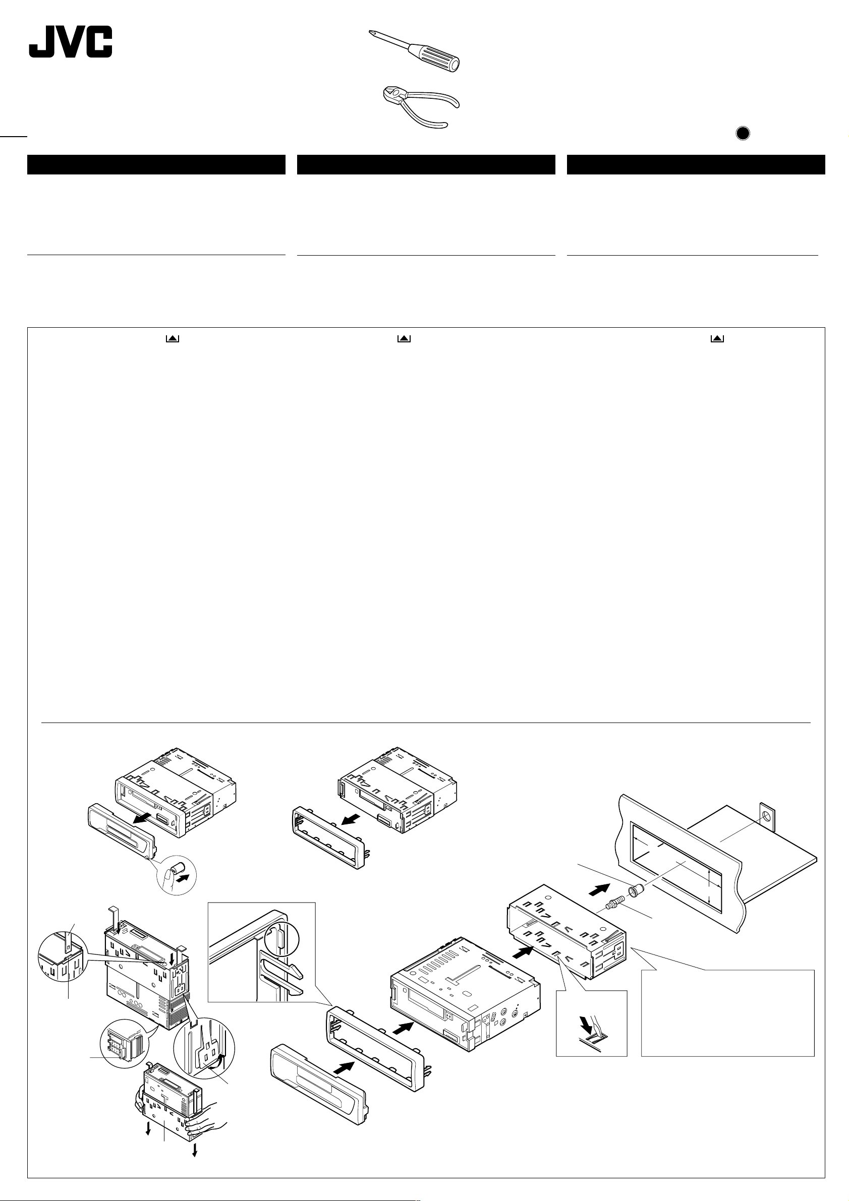
INSTALLATION
(IN-DASH MOUNTING)
• The following illustration shows a typical installation. However,
you should make adjustments corresponding to your specific
car. If you have any questions or require information regarding
installation kits, consult your JVC IN-CAR ENTERTAINMENT
dealer or a company supplying kits.
1
Before mounting: Press (Control Panel Release
button) to detach the control panel.
2
Remove the trim plate.
3
Remove the sleeve after disengaging the sleeve locks.
1 Stand the unit.
Note: When you stand the unit, be careful not to damage
the fuse on the rear.
2 Insert the 2 handles between the unit and the sleeve, as
illustrated, to disengage the sleeve locks.
3 Remove the sleeve.
Note: Be sure to keep the handles for future use after
installing the unit.
4
Install the sleeve into the dashboard.
* After the sleeve is correctly installed into the dashboard,
bend the appropriate tabs to hold the sleeve firmly in place,
as illustrated.
5
Fix the mounting bolt to the rear of the unit’s body and place
the rubber cushion over the end of the bolt.
6
Do the required electrical connections.
7
Slide the unit into the sleeve until it is locked.
8
Attach the trim plate so that the projection on the trim plate
is fixed to the left side of the unit.
9
Attach the control panel.
DEUTSCH
• Dieses Gerät ist nur für einen Betrieb in elektrischen Anlagen
mit 12 V Gleichstrom und (–) Erdung ausgelegt.
EINBAU
(IM ARMATURENBRETT)
• Die folgende Abbildung zeigt einen typischen Einbau. Dennoch
müssen Sie entsprechend Ihrem jeweiligen Auto Anpassungen
vornehmen. Bei irgendwelchen Fragen oder wenn Sie
Informationen hinsichtlich des Einbausatzes brauchen, wenden
Sie sich an ihren JVC Autoradiohändler oder ein Unternehmen
das diese Einbausätze vertreibt.
1
Vor dem Einbau: (Schalttafel-Freigabetaste) zum
Lösen der Schalttafel drücken.
2
Den Frontrahmen herausnehmen.
3
Die Halterung nach dem Entriegeln der Halterungensperren
abnehmen.
1 Das Gerät aufstellen.
Hinweis: Beim Aufstellen des Geräts darauf achten,
daß die Sicherung auf der Rückseite nicht beschädigt
wird.
2 Die beiden Griffe zwischen dem Gerät und der
wie abgebildet einstecken und die
entriegeln.
3 Die
Halterung
Hinweis: Sicherstellen, daß die Griffe für künftigen
Gebrauch nach dem Einbau des Geräts aufbewahrt
werden.
4
Die
Halterung
* Nach dem korrekten Einbau der
Armaturenbrett, die entsprechenden Riegel umknicken,
um die
Abbildung.
5
Die Befestigungsschraube an der Rückseite des
Gerätekörpers befestigen und das Ende der Schraube mit
einem Gummipuffer abdecken.
6
Nehmen Sie die erforderlichen elektrischen Anschlüsse vor .
7
Das Gerät in die
8
Befestigen Sie die Frontrahmen in der Form, daß der
Fortsatz der Frontrahmen auf der linken Seite des Geräts
befestigt wird.
9
Die Schalttafel anbringen.
entfernen.
im Armaturenbrett einbauen.
Halterung
an ihrem Platz zu sichern, siehe
Halterung
schieben, bis es einrastet.
Halterungensperren
Halterung
Halterung
im
0800HISFLEJES
JVC
EN, GE, FR
FRANÇAIS
•
Cet appareil est conçu pour fonctionner sur des sources de
courant continu de 12 volts à masse NEGATIVE.
INSTALLATION
(MONT AGE DANS LE TABLEAU DE BORD)
•
L’illustration suivante est un exemple d’installation typique.
Cependant, vous dev ez faire les ajustements correspondant à
votre voiture particulière. Si vous avez des questions ou avez
besoin d’information sur des kits d’installation, consulter votre
revendeur d’autoradios JVC ou une compagnie
d’approvisionnement.
1
Avant le montage:
du panneau de commande) pour détacher le panneau de
commande.
2
Retirer la plaque d’assemblage.
3
Libérer les verrous du manchon et retirer le manchon.
1
Poser l’appareil à la verticale.
Remarque:
faire attention de ne pas endommager le fusible situé
sur le fond.
2
Insérer les 2 poignées entre l’appareil et le manchon
comme indiqué pour désengagé les verrous de manchon.
3
Retirer le manchon.
Remarque:
utilisation ultérieur, après l'installation de l'appareil.
4
Installer le manchon dans le tableau de bord.
* Après installation correcte du manchon dans le tableau
de bord, plier les bonnes pattes pour maintenir fermement
le manchon en place, comme montré.
5
Monter le boulon de montage sur l’arrière du corps de
l’appareil puis passer l’amor tisseur en caoutchouc sur
l’extrémité du boulon.
6
Réalisez les connexions électriques.
7
Faire glisser l’appareil dans le manchon jusqu’à ce qu’il soit
verrouillé.
8
Attachez la plaque d’assemblage de façon que la projection
de la plaque soit fixée sur le côté gauche de l’appareil.
9
Remonter le panneau de commande.
Appuyer sur (touche de libération
Lorsque vous mettez l’appareil à la verticale,
S'assurer de garder les poignées pour une
1
3
Handles
Griffe
Poignées
Slot
Schlitz
Fente
Fuse
Sicherung
Fusible
2
9
8
Rubber cushion
Gummipuffer
Amortisseur en caoutchouc
Sleeve
Halterung
Manchon
7
4
4
Dashboard
Armaturenbrett
Tableau de bord
5
Mounting bolt
Befestigungsschraube
Boulon de montage
6
See the back page for electrical
*
connections.
Siehe Rückseite für elektrische
Anschlüsse.
Voir le dos de cette page pour les
connexions électriques.
Sleeve
Halterung
Manchon
Lock plate
Arretierplättchen
Plaque de verrouillage
Trim plate
Frontrahmen
Plaque d’assemblage
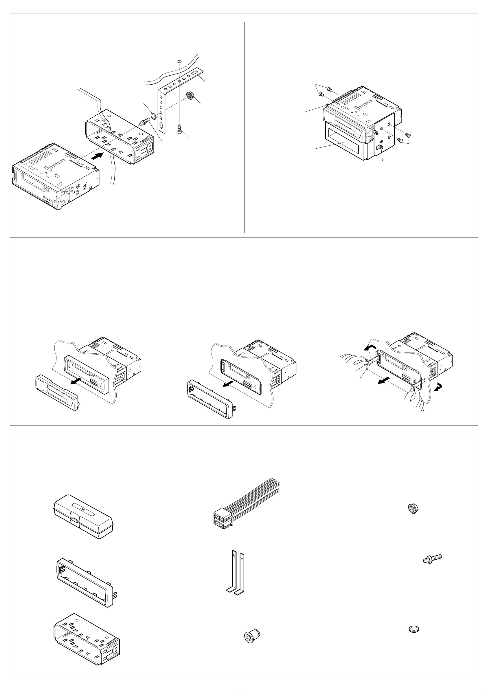
•When using the optional stay
•Beim Verwenden der Anker-Option
•Lors de l'utilisation du hauban en option
Washer
Dashboard
Armaturenbrett
Tableau de bord
Unterlegscheibe
Rondelle
Sleeve
Halterung
Manchon
Fire wall
Feuerwand
Cloison
Mounting bolt
Befestigungsschraube
Boulon de montage
Stay (option)
Anker (Option)
Hauban (en option)
Lock nut
Sicherungsmutter
Ecrou d’arrêt
Screw (option)
Schraube (Option)
Vis (en option)
•When installing the unit without using the sleeve
•Beim Einbau des Geräts ohne Halterung
•Lors de l'installation de l’appareil sans utiliser de manchon
In a Toyota for example, first remove the car radio and install the unit in its place.
Zum Beispiel in einem T oyota zuerst das Autoradio ausbauen und dann das Gerät an seinem Platz einbauen.
Par exemple dans une Toyota, retirer d’abord l’autoradio et installer l’appareil à la place.
Flat type screws (M5 x 6 mm)*
Senkkopfschrauben (M5 x 6 mm)*
Vis à tête plate (M5 x 6 mm)*
Bracket*
Konsole*
Support*
Pocket
Taschen
Poche
Nota: When installing the unit on the mounting brac k et, mak e sure to use the 6 mm-long scre ws . If
longer screws are used, they could damage the unit.
* Not included with this unit.
* Nicht Teil dieses Geräts.
Non fourni avec cet appareil.
*
Flat type screws (M5 x 6 mm)*
Senkkopfschrauben (M5 x 6 mm)*
Bracket*
Konsole*
Support*
Vis à tête plate (M5 x 6 mm)*
Removing the unit
• Before removing the unit, release the rear section.
1
Remove the control panel.
2
Remove the trim plate.
3
Insert the 2 handles into the slots, as shown. Then, while
gently pulling the handles away from each other, slide out the
unit. (Be sure to keep the handles after installing it.)
Hinweis: Beim Anbringen des Gerät an der Konsole sicherstellen, daß 6 mm lange Schrauben
verwendet werden. Werden längere Schrauben verwendet, können sie das Gerät beschädigen.
Remarque:
Lors de l'installation de l’appareil sur le support de montage, s’assurer d’utiliser des vis
d’une longueur de 6 mm. Si des vis plus longues sont utilisées, elles peuvent endommager l’appareil.
Ausbau des Geräts
• Vor dem Ausbau des Geräts den hinteren Teil freigeben.
1
Die Schalttafel abnehmen.
2
Den Frontrahmen abnehmen.
3
Die 2 Griffe in die Schlitze wie gezeigt stecken. Dann die Griffe
behutsam auseinander ziehen und das Gerät herausziehen.
(Die Griffe nach dem Einbau auf jeden Fall aufbewahren.)
Retrait de l’appareil
•
Avant de retirer l’appareil, libérer la section arrière.
1
Retirer le panneau de commande.
2
Retirer la plaque d’assemblage.
3
Introduire les deux poignées dans les fentes, comme montré.
Puis, tout en tirant doucement les poignées écartées, faire
glisser l’appareil pour le sortir.
(S'assurer de conserver les
poignées après l’installation de l’appareil.)
312
Parts list for installation and connection
The following parts are provided with this unit.
After checking them, please set them correctly.
Hard case
Etui
Etui de transport
Tr im plate
Frontrahmen
Plaque d’assemblage
Teileliste für den Einbau und Anschluß
Die folgenden T eile werden zusammen mit diesem Gerät geliefert.
Nach ihrer Überprüfung, die Teile richtig einsetzen.
Power cord
Spannunsgversorgungskabel
Cordon d’alimentation
Handles
Griffe
Poignées
Handle
Griff
Poignée
Liste des pièces pour l’installation et raccordement
Les pièces suivantes sont fournies avec cet appareil.
Après vérification, veuillez les placer correctement.
Lock nut (M5)
Sicherungsmutter (M5)
Ecrou d’arrêt (M5)
Mounting bolt (M5 x 20 mm)
Befestigungsschrauben (M5 x 20 mm)
Boulon de montage (M5 x 20 mm)
Sleeve
Halterung
Manchon
Rubber cushion
Gummipuffer
Amortisseur en caoutchouc
Washer (ø5)
Unterlegscheibe(ø5)
Rondelle (ø5)
 Loading...