

Page 1
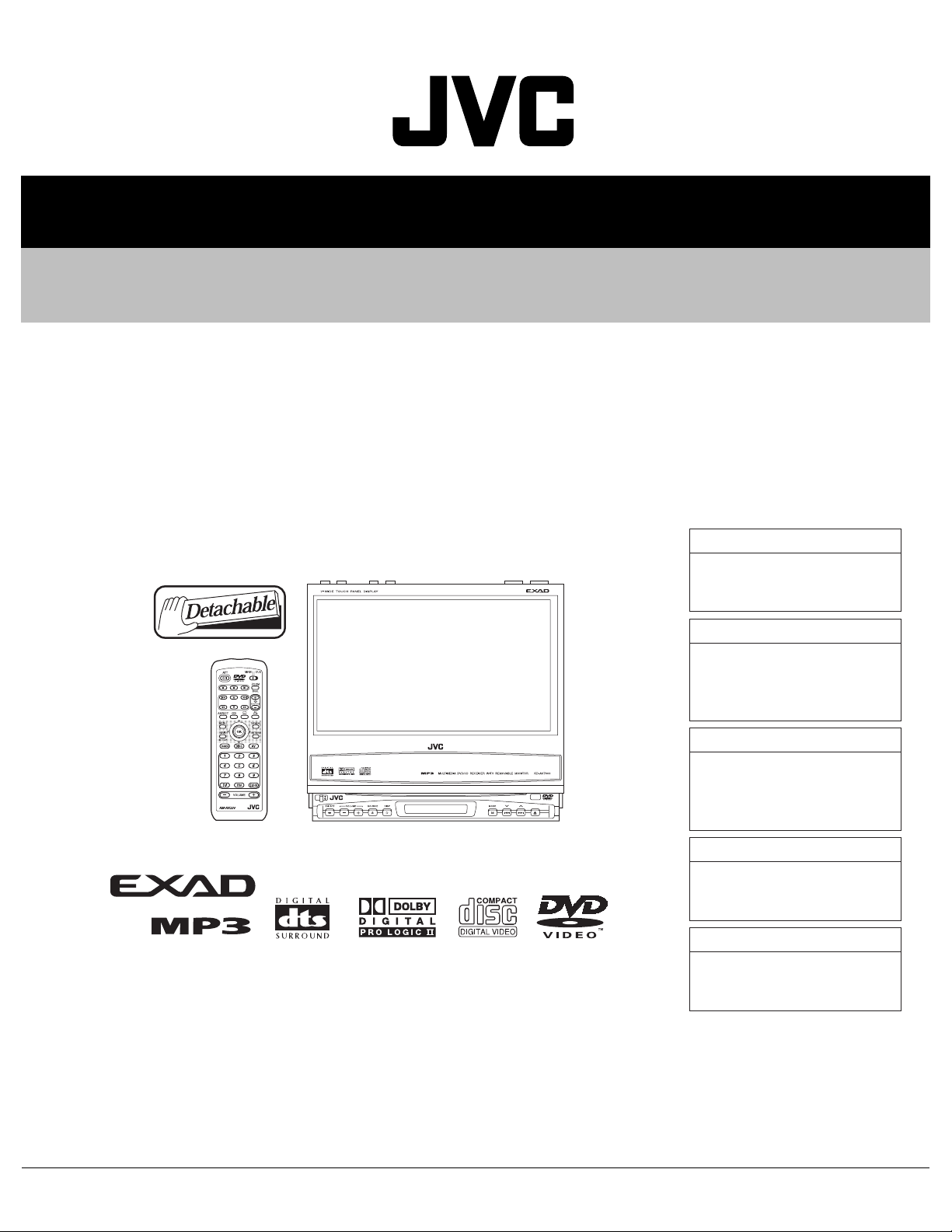
SERVICE MANUAL
DVD RECEIVER WITH MONITOR
MA10120051
KD-AV7000,KD-AV7001,
KD-AV7005,KD-AV7008,
KV-MAV7001,KV-MAV7002
KD-AV7000
Area suffix
J ------------- Northern America
KD-AV7001
Area suffix
E ------------- Southern Europe
EU ------------------------- Turkey
KD-AV7005
Area suffix
UN --------------------------Asean
U -------------------- Other Areas
KD-AV7008
Area suffix
A ------------------------ Australia
KV-MAV7001,KV-MAV7002
Area suffix
U -------------------- Other Areas
TABLE OF CONTENTS
1 PRECAUTIONS . . . . . . . . . . . . . . . . . . . . . . . . . . . . . . . . . . . . . . . . . . . . . . . . . . . . . . . . . . . . . . . . . . . . . . . 1-4
2 SPECIFIC SERVICE INSTRUCTIONS . . . . . . . . . . . . . . . . . . . . . . . . . . . . . . . . . . . . . . . . . . . . . . . . . . . . . . 1-7
3 DISASSEMBLY . . . . . . . . . . . . . . . . . . . . . . . . . . . . . . . . . . . . . . . . . . . . . . . . . . . . . . . . . . . . . . . . . . . . . . . 1-8
4 ADJUSTMENT . . . . . . . . . . . . . . . . . . . . . . . . . . . . . . . . . . . . . . . . . . . . . . . . . . . . . . . . . . . . . . . . . . . . . . . 1-35
5 TROUBLESHOOTING . . . . . . . . . . . . . . . . . . . . . . . . . . . . . . . . . . . . . . . . . . . . . . . . . . . . . . . . . . . . . . . . . 1-51
COPYRIGHT © 2005 Victor Company of Japan, Limited
No.MA101
2005/1
Page 2
SPECIFICATION
Main unit
AUDIO AMPLIFIER SECTION
Maximum Power Output Front 50 W per channel
Rear 50 W per channel
Center 35 W
Continuous Power Output
(RMS)
Load Impedance 4 Ω (4 Ω to 8 Ω allowance)
Equalizer Control Range Frequencies 100 Hz, 300 Hz, 1 kHz, 3 kHz, 10 kHz
Frequency Response 40 Hz to 20 000 Hz
Signal-to-Noise Ratio 70 dB
Frequency Range FM 87.5 MHz to 107.9 MHz
FM Tuner Usable Sensitivity 11.3 dBf (1.0 µV/75 Ω)
AM Tuner Sensitivity 20 µV
LW Tuner Selectivity 50 µV (KV7001 only)
Signal Detection System Non-contact optical pickup (semiconductor laser)
Number of channels 2 channels (stereo)
Frequency Response DVD, fs=48 kHz 16 Hz to 22 000 Hz
Dynamic Range 96 dB
Signal-to-Noise Ratio 98 dB
Wow and Flutter Less than measurable limit
MP3 Recording Format MPEG 1/2 Audio Layer 3
Front 19 W per channel into 4 Ω, 40 Hz to 20 000 Hz at no more than
0.8% total harmonic distortion.
Rear 19 W per channel into 4 Ω, 40 Hz to 20 000 Hz at no more than
0.8% total harmonic distortion.
Center 15 W into 4 Ω, 40 Hz to 20 000 Hz at no more than 0.8% total
harmonic distortion.
Level ±10 dB
TUNER SECTION
AM 530 kHz to 1 710 kHz
50 dB Quieting Sensitivity 16.3 dBf (1.8 µV/75 Ω)
Alternate Channel Selectivity (400 kHz) 65 dB
Frequency Response 40 Hz to 15 000 Hz
Stereo Separation 35 dB
Capture Ratio 1.5 dB
Selectivity 35 dB
DVD/CD PLAYER SECTION
DVD, fs=96 kHz 16 Hz to 44 000 Hz
VCD, CD, MP3 16 Hz to 20 000 Hz
Max. Bit rate: 320 kbps
1-2 (No.MA101)
Page 3
REMOVABLE MONITOR
Screen Size 7 inch wide liquid crystal display
Number of Pixel 336 960 pixels (480 vertical × 234 horizontal × 3)
Drive Method TFT (Thin Film Transistor) active matrix format
Color System NTSC
Aspect Ratio 16:9 (wide)
Allowable Storage Temperature -10°C to +60°C (14°F to 140°F)
Allowable Operating Temperature 0°C to +40°C (32°F to 104°F)
Dimensions (W × H × D) 170 mm × 141 mm × 15 mm (6-3/4 in. × 5-5/8 in. × 5/8 in.)
Mass 475 g (1.1 lbs)
GENERAL
Power Requirement Operating Voltage DC 14.4 V (11 V to 16 V allowance)
Grounding System Negative ground
Allowable Operating Temperature 0°C to +40°C (32°F to 104°F)
Dimensions (W × H × D) Installation Size 182 mm × 52 mm × 165 mm (7-3/16 in. × 2-1/16 in. × 6-1/2 in.)
(With sleeve-mounting plate Type B (standard))
182 mm × 52 mm × 160 mm (7-3/16 in. × 2-1/16 in. × 6-5/16 in.)
(With sleeve-mounting plate Type A)
Panel Size 188 mm × 58 mm × 14 mm (7-7/16 in. × 2-5/16 in. × 5/8 in.)
Mass 2.25 kg (5.1 lbs) (including monitor)
Hideaway unit
Input Terminals AV INPUT 1/2 Audio: 0.5 Vrms (Left/Right)
Video (composite): 1 Vp-p/75 Ω
Output Terminals (Level/Impedance) AV OUTPUT Audio: 2.0 V/20 kΩ load (full scale)
Video (composite): 1 Vp-p/75 Ω
PRE OUT Audio: 2.0 V/20 kΩ load (full scale)
Other Terminals System integration (TO MAIN UNIT)
FM/AM antenna (FM/AM ANTENNA)
AV bus (AV BUS)
CD changer (TO CHANGER)
Rear view camera/Center speaker (BACKCAMERA REMOTE/CENTER
SPEAKER)
Power cord (POWER)
Dimensions (W × H × D) 230 mm × 35 mm × 181 mm (9-1/16 in. × 1-7/16 in. × 7-3/16 in.)
Mass 1.3 kg (2.9 lbs)
Design and specifications are subject to change without notice.
(No.MA101)1-3
Page 4
1.1 Safety Precautions
SECTION 1
PRECAUTIONS
!
!
Burrs formed during molding may be left over on some parts of the chassis. Therefore,
pay attention to such burrs in the case of preforming repair of this system.
Please use enough caution not to see the beam directly or touch it in case of an
adjustment or operation check.
1-4 (No.MA101)
Page 5
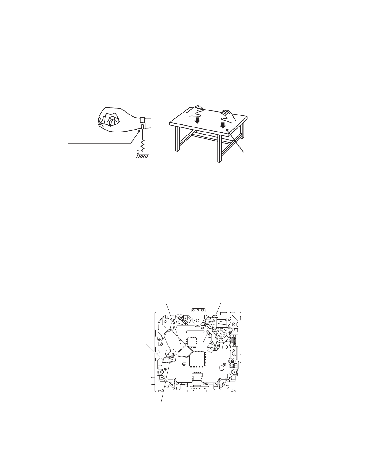
1.2 Preventing static electricity
Electrostatic discharge (ESD), which occurs when static electricity stored in the body, fabric, etc. is discharged, can destroy the laser
diode in the traverse unit (optical pickup). Take care to prevent this when performing repairs.
1.2.1 Grounding to prevent damage by static electricity
Static electricity in the work area can destroy the optical pickup (laser diode) in devices such as CD players.
Be careful to use proper grounding in the area where repairs are being performed.
(1) Ground the workbench
Ground the workbench by laying conductive material (such as a conductive sheet) or an iron plate over it before placing the
traverse unit (optical pickup) on it.
(2) Ground yourself
Use an anti-static wrist strap to release any static electricity built up in your body.
(caption)
Anti-static wrist strap
1M
Conductive material
(conductive sheet) or iron plate
(3) Handling the optical pickup
• In order to maintain quality during transport and before installation, both sides of the laser diode on the replacement optical
pickup are shorted. After replacement, return the shorted parts to their original condition.
(Refer to the text.)
• Do not use a tester to check the condition of the laser diode in the optical pickup. The tester's internal power source can easily
destroy the laser diode.
1.3 Handling the traverse unit (optical pickup)
(1) Do not subject the traverse unit (optical pickup) to strong shocks, as it is a sensitive, complex unit.
(2) Cut off the shorted part of the flexible cable using nippers, etc. after replacing the optical pickup. For specific details, refer to the
replacement procedure in the text. Remove the anti-static pin when replacing the traverse unit. Be careful not to take too long a
time when attaching it to the connector.
(3) Handle the flexible cable carefully as it may break when subjected to strong force.
(4) It is not possible to adjust the semi-fixed resistor that adjusts the laser power. Do not turn it.
1.4 Attention when traverse unit is decomposed
*Please refer to "Disassembly method" in the text for the CD pickup unit.
• Apply solder to the short land before the flexible wire is disconnected from the connector on the CD pickup unit.
(If the flexible wire is disconnected without applying solder, the CD pickup may be destroyed by static electricity.)
• In the assembly, be sure to remove solder from the short land after connecting the flexible wire.
Flexible wire
Front end board
CN101
Short-circuit points
(No.MA101)1-5
Page 6
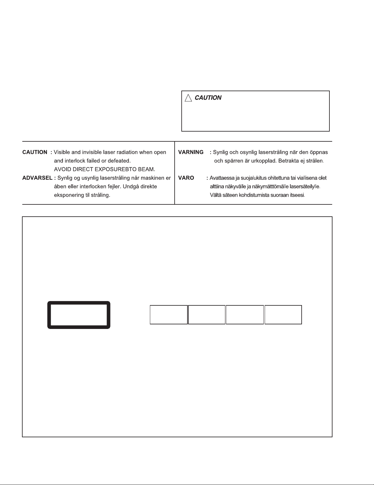
1.5 Important for laser products
!
1.CLASS 1 LASER PRODUCT
2.DANGER : Invisible laser radiation when open and inter
lock failed or defeated. Avoid direct exposure to beam.
3.CAUTION : There are no serviceable parts inside the
Laser Unit. Do not disassemble the Laser Unit. Replace
the complete Laser Unit if it malfunctions.
4.CAUTION : The CD,MD and DVD player uses invisible
laser radiation and is equipped with safety switches which
prevent emission of radiation when the drawer is open and
the safety interlocks have failed or are defeated. It is
dangerous to defeat the safety switches.
5.CAUTION : If safety switches malfunction, the laser is able
to function.
6.CAUTION : Use of controls, adjustments or performance of
procedures other than those specified here in may result in
hazardous radiation exposure.
Please use enough caution not to
see the beam directly or touch it
in case of an adjustment or operation
check.
REPRODUCTION AND POSITION OF LABELS
WARNING LABEL
CAUTION : Visible and Invisible
CLASS 1
LASER PRODUCT
laser radiation when open and
interlock failed or defeated.
AVOID DIRECT EXPOSURE TO
BEAM. (e)
ADVARSEL : Synlig og usynlig
laserstråling når maskinen er
åben eller interlocken fejeler.
Undgå direkte eksponering til
stråling. (d)
VARNING : Synlig och
osynling laserstrålning när
den öppnas och spärren är
urkopplad. Betrakta ej
strålen. (s)
VARO : Avattaessa ja suojalukitus
ohitettuna tai viallisena olet alttiina
näkyvälle ja näkymättömälle
lasersäteilylle. Vältä säteen
kohdistumista suoraan itseesi. (f)
1-6 (No.MA101)
Page 7

SECTION 2
SPECIFIC SERVICE INSTRUCTIONS
This service manual does not describe SPECIFIC SERVICE INSTRUCTIONS.
(No.MA101)1-7
Page 8
SECTION 3
DISASSEMBLY
3.1 Receiver unit section
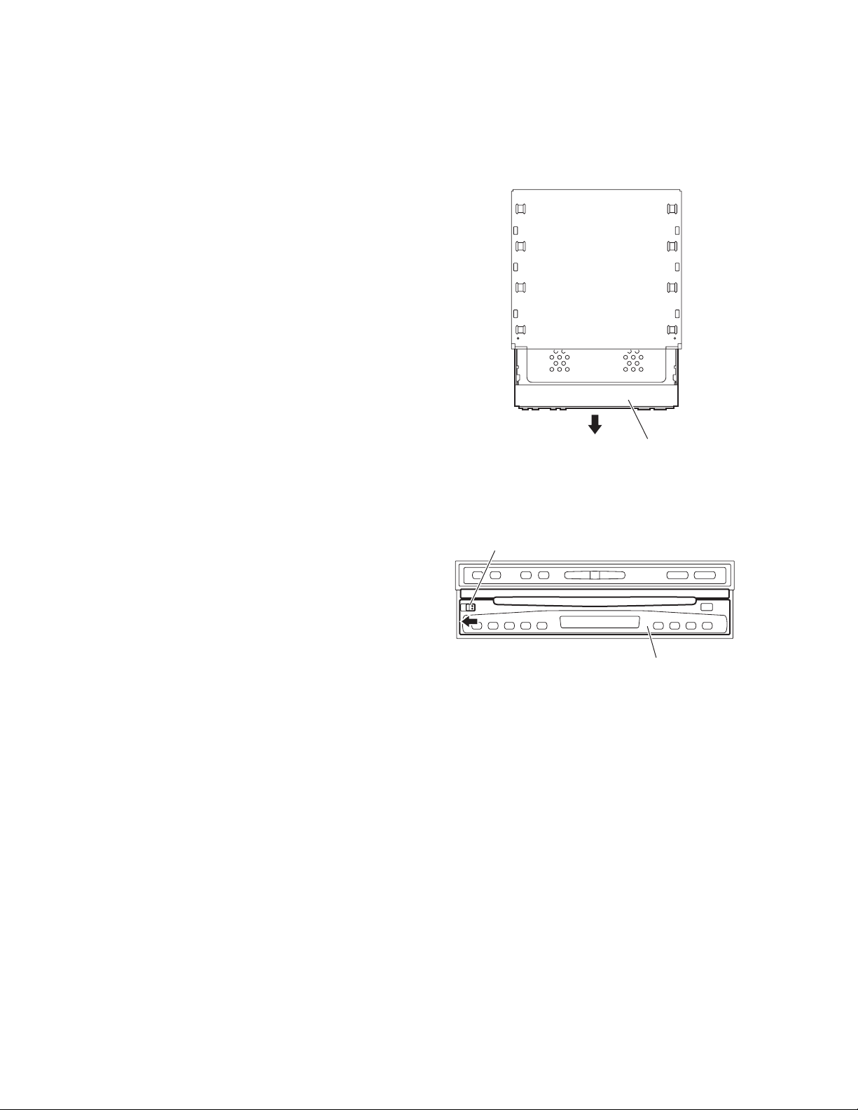
3.1.1 Removing the display unit
(See Fig.1)
From the top side of the main body, pull the display unit out of the
main body in the direction of the arrow.
3.1.2 Removing the detach panel assembly
(See Fig.2)
From the front side of the main body, slide the detach button in
the direction of the arrow and remove the detach panel assembly.
Display unit
Fig.1
Detach button
Detach panel assembly
Fig.2
1-8 (No.MA101)
Page 9
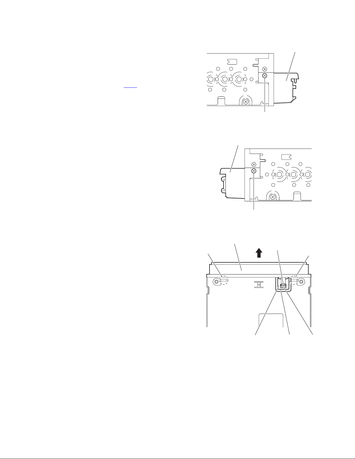
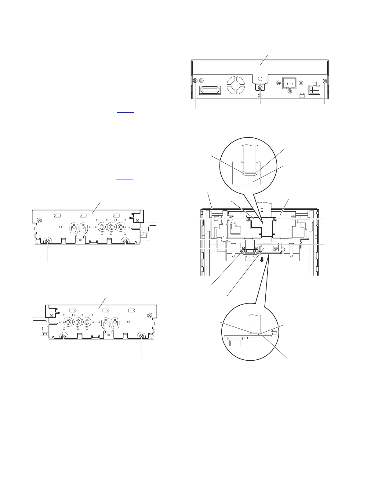
3.1.3 Removing the front panel assembly
(See Figs.3 to 5)
• Remove the display unit and detach panel assembly as re-
quired.
(1) From the both sides of the main body, remove the two
screw A attaching the front panel assembly. (See Figs.3
and 4)
(2) From the bottom side of the main body, remove the FPC
cover. (See Fig.5.)
(3) Release the lock of the connector CN75
and disconnect the card wire. (See Fig.5.)
(4) Release the joints a and remove the front panel assembly
from the main body in the direction of the arrow. (See
Fig.5.)
on the main board
Front panel assembly
A
Fig.3
Front panel assembly
Front panel assembly
a
Main board
A
Fig.4
Fig.5
Lock
FPC cover
a
CN75
(No.MA101)1-9
Page 10
3.1.4 Removing the top drive unit
(See Figs.6 to 9)
• Prior to performing the following procedures, remove the dis-
play unit, detach panel assembly and front panel assembly.
(1) From the both sides of the main body, remove the four
screws B attaching the top drive unit. (See Figs.6 and 7.)
(2) From the rear side of the main body, remove the three
screws C attaching the top drive unit. (See Fig.8.)
(3) Remove the top drive unit from the main body and turn it
inside out. (See Fig.9.)
(4) Remove the two screws C attaching the F.P.C. guide on
the display drive unit. (See Fig.9.)
(5) Release the lock of the connector CN301
nism board and disconnect the flexible wire. (See Fig.9.)
(6) Remove the two screws D attaching the CN guide. (See
Fig.9.)
(7) Remove the three screws E attaching the PWB base. (See
Fig.9.)
(8) Remove the screw F attaching the connect board. (See
Fig.9.)
(9) Take out the connect board in the direction of the arrow.
(See Fig.9.)
(10) Release the lock of the connector CN391
board and disconnect the flexible wire. (See Fig.9.)
Top drive unit
on the mecha-
on the connect
B
Lock
Top drive unit
F.P.C.guide
Top drive unit
Fig.8
CN301
Motor board
Display drive unit
B
Fig.6
Top drive unit
Fig.7
B
C
D
E
CN guide
PWB base
Lock
C
E
F
CN391
Connect board
Fig.9
1-10 (No.MA101)
Page 11

3.1.5 Removing the rear bracket
(See Figs.10)
• Prior to performing the following procedures, remove the dis-
play unit, detach panel assembly, front panel assembly and top
drive unit.
From the rear side of the main body, remove the five screws G
attaching the rear bracket.
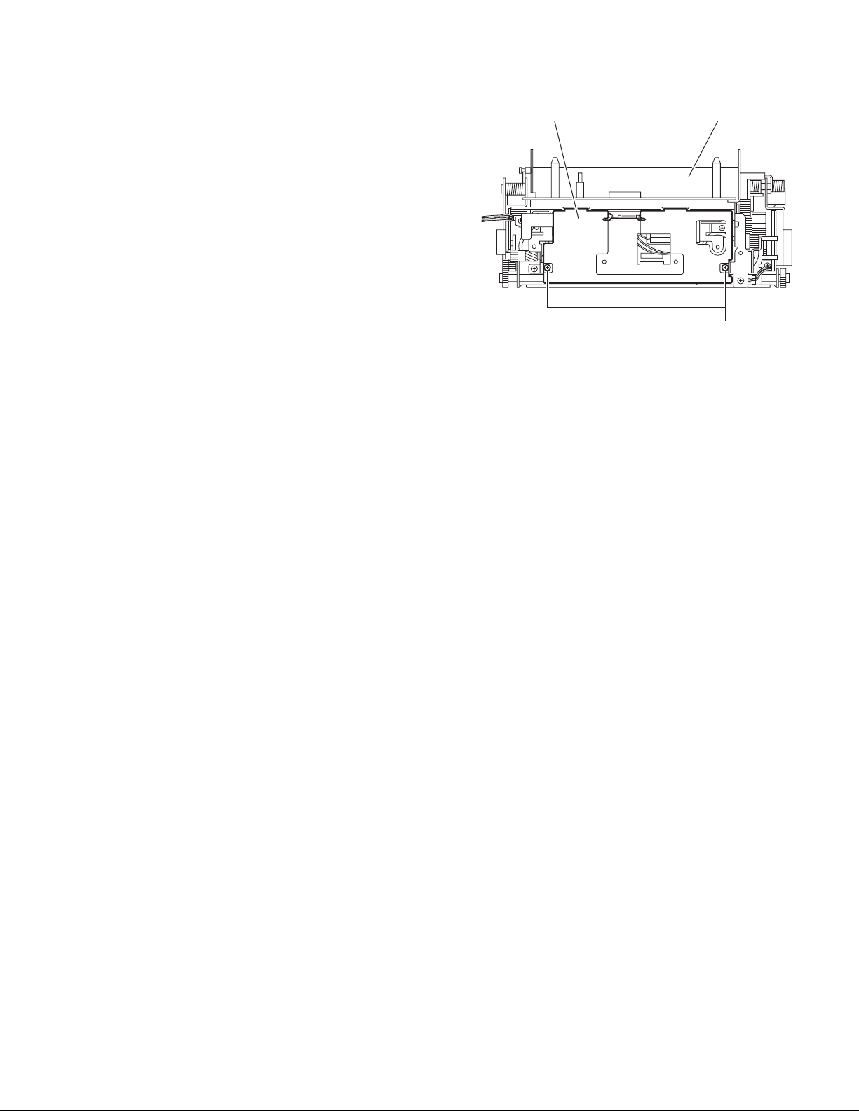
3.1.6 Removing the DVD mechanism assembly
(See Figs.11 and 12)
• Prior to performing the following procedures, remove the dis-
play unit, detach panel assembly, front panel assembly and top
drive unit.
(1) From the top side of the main body, release the lock of the
connector CN52
and disconnect the flexible wire. (See Fig.11.)
(2) Remove the two screws H and screw J attaching the mech-
anism cover. (See Fig.11.)
(3) Release the lock of the connector CN101
board in an upward direction and disconnect the card wire.
(See Fig.12.)
Reference:
When connecting the card wire to the connector CN101
it through the lower part of the mechanism bracket. (See
Fig.12.)
on the main board in an upward direction
on the main
, pass
Rear bracket
G
Fig.10
Flexible wire
Mechanism cover
HH
CN52
DVD mechanism assembly
Main board
J
Fig.11
CN101
Fig.12
Main board
Mechanism bracket
(No.MA101)1-11
Page 12
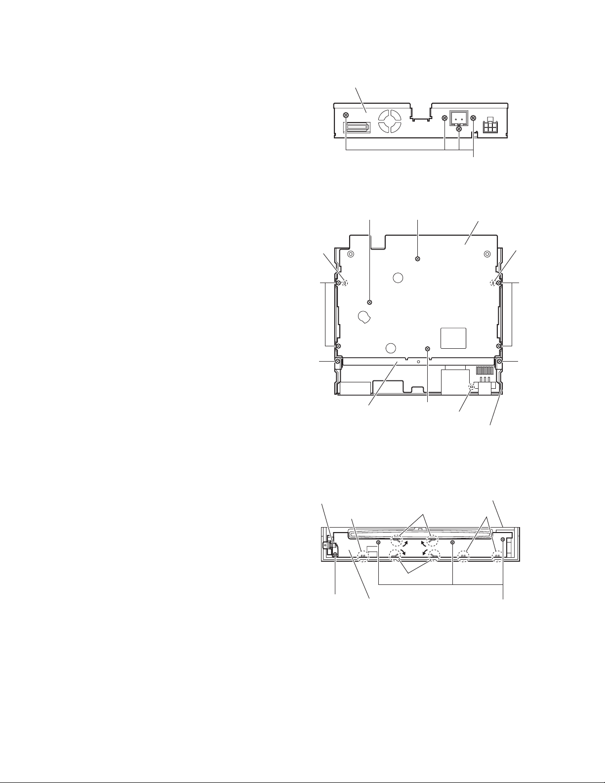
3.1.7 Removing the main board
(See Figs.13 and 14)
• Prior to performing the following procedures, remove the dis-
play unit, detach panel assembly, front panel assembly, top
drive unit and DVD mechanism assembly.
(1) From the rear side of the main body, remove the four
screws K attaching the rear bracket. (See Fig.13.)
(2) From the top side of the main body, remove the two screws
L attaching the mechanism bracket on the bottom chassis
assembly. (See Fig.14.)
(3) Remove the five screws M and two screws N attaching the
main board. (See Fig.14.)
(4) Take out the main board from the bottom chassis assem-
bly.
Reference:
When attaching the main board on the bottom chassis assembly, align the projections b of the bottom chassis assembly in
the hole of the main board. (See Fig.14.)
Rear bracket
b
Fig.13
MN
K
Main board
b
3.1.8 Removing the front board
(See Fig.15)
• Prior to performing the following procedures, remove the de-
tach panel assembly and front panel assembly.
(1) From the inside of the front panel assembly, remove the
three screws P and screw P' attaching the front board.
(2) Take out the lock lever assembly from the front panel as-
sembly.
(3) Bend the hooks c in the direction of the arrow.
(4) Release the front board from the sections d and take out
the front board from the front panel assembly.
Reference:
When attaching the screw P', attach the lock lever assembly
with it.
M
L
Mechanism bracket
Lock lever assembly
d
Front board
P'
N
Fig.14
c
c
b
Bottom chassis assembly
Front panel assembly
M
L
d
P
1-12 (No.MA101)
Fig.15
Page 13
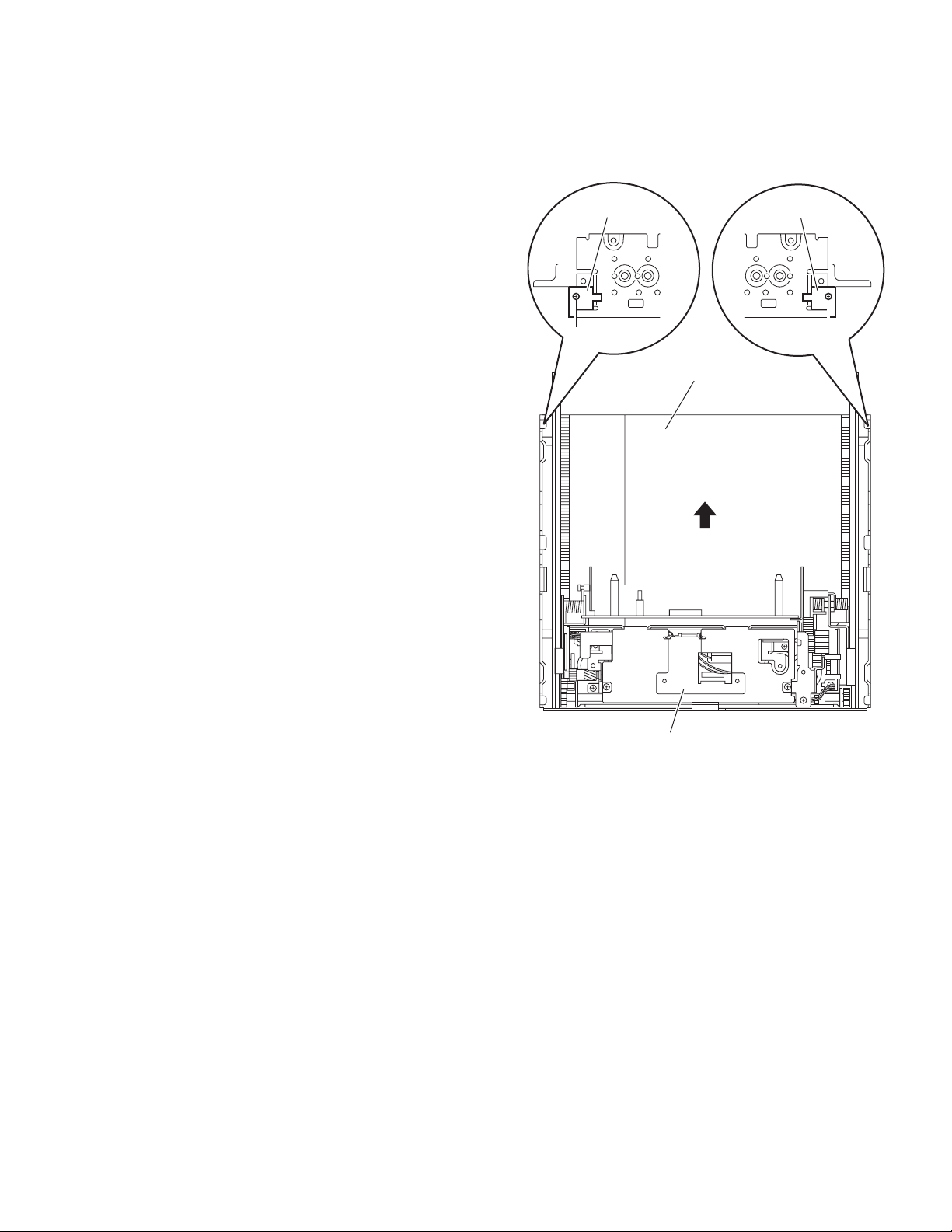
3.2 Top drive unit section
• Remove the top drive unit from the main body.
(See "3.1.4 Removing the top drive unit".)
3.2.1 Removing the display drive unit
(See Fig.1)
(1) From the both sides of the top drive unit, remove the two
screws A attaching the display guides L/R and remove the
display guides L/R from the top chassis assembly.
(2) Slide the display drive unit by manual operation in the di-
rection of the arrow and remove it from the top chassis assembly.
Display guide L
Display guide R
A
Display drive unit
A
Top chassis assembly
Fig.1
(No.MA101)1-13
Page 14
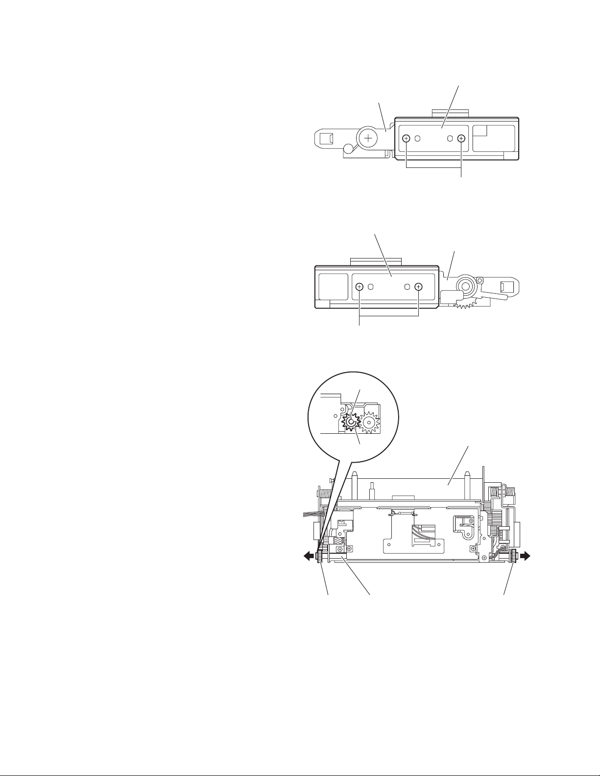
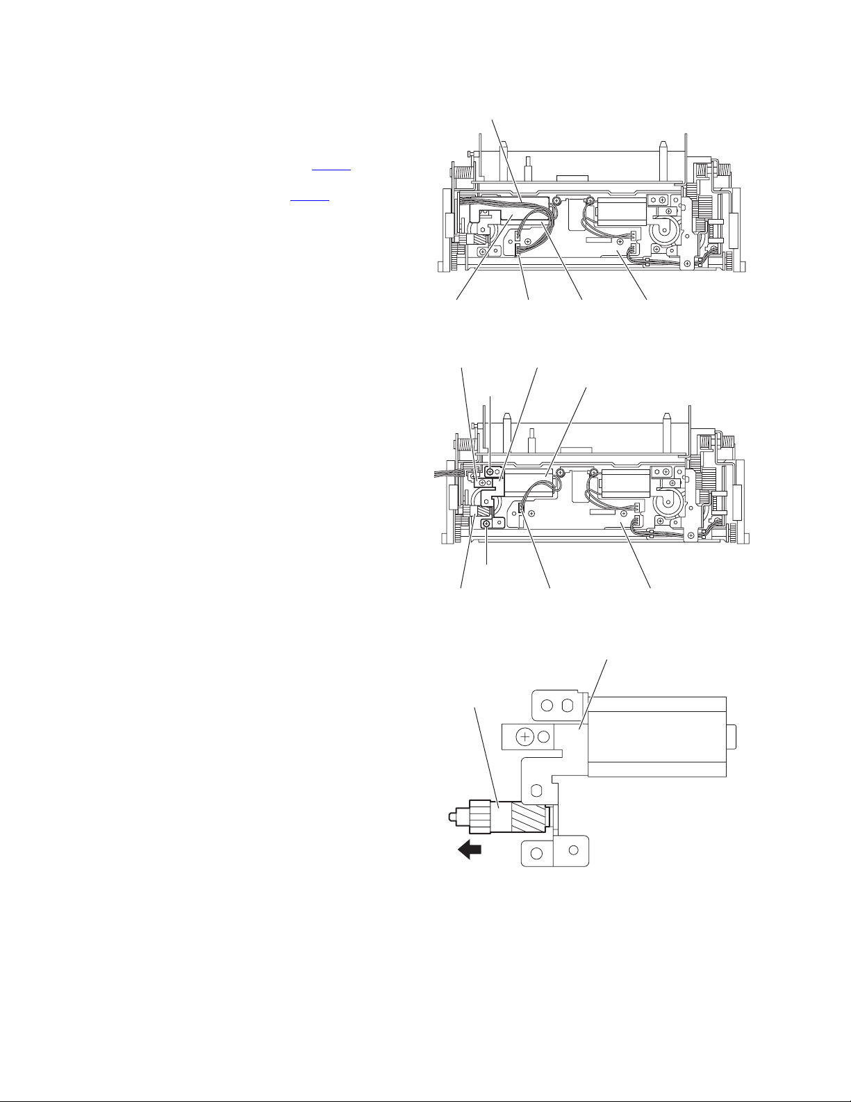
3.2.2 Removing the drive gears and forth gear
(See Figs.2 to 4)
• Remove the display drive unit.
(1) From the both sides of the display drive unit, remove the
four screws B attaching the guide rails (L)/(R). (See Figs.2
and 3.)
(2) From the top side of the display drive unit, pull the drive
gears out of a drive gear shaft in the direction of the arrow
while holding the drive gear shaft. (See Fig.4.)
Reference:
Remove the drive gear shaft as required. (See Fig.4.)
(3) From the left side of the display drive unit, remove the
E.ring fixing the forth gear. (See Fig.4.)
(4) Remove the forth gear toward this side. (See Fig.4.)
Guide rail (L)
Display drive unit
B
Fig.2
Guide rail (R)
Display drive unit
B
Fig.3
E.ring
Forth gear
Drive gear Drive gearDrive gear shaft
Fig.4
Display drive unit
1-14 (No.MA101)
Page 15
3.2.3 Removing the cover
(See Fig.5)
• Remove the display drive unit.
From the top side of the display drive unit, remove the two
screws C attaching the cover.
Display drive unitCover
C
Fig.5
(No.MA101)1-15
Page 16
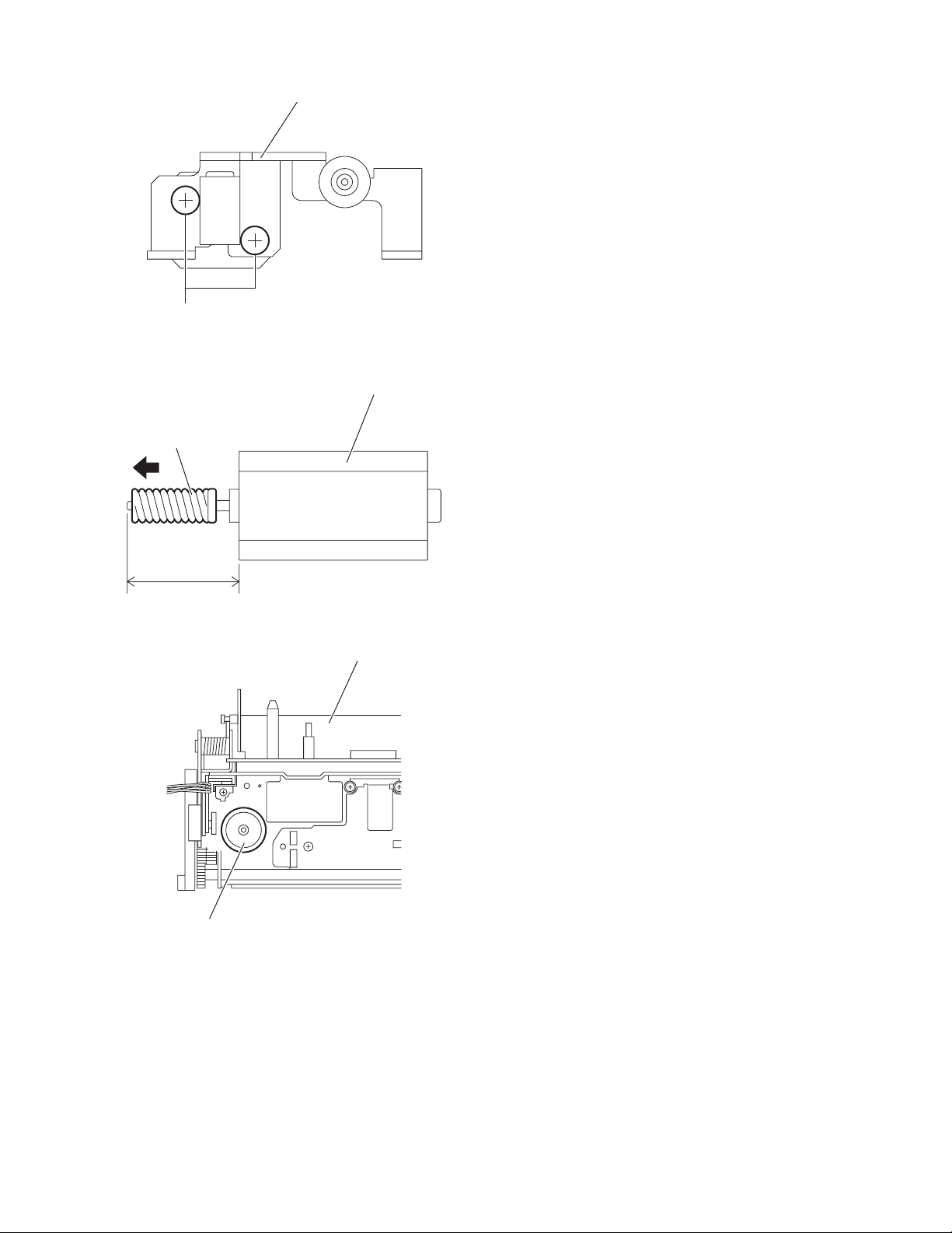
3.2.4 Removing the third gear, worm gear and double worm
(See Figs.6 to 11)
• Remove the display drive unit and cover.
(1) Remove the wire sheet with the wire from the motor. (See
Fig.6.)
Reference:
Disconnect the wire from the connector CN332
motor board as required.
(2) Disconnect the wire from the connector CN312
tor board. (See Fig.7.)
(3) Remove the two screws D attaching the motor bracket (S).
(See Fig.7.)
(4) Take out the motor bracket (S), worm guide, motor and
third gear together. (See Fig.7.)
(5) Pull the third gear out of the motor bracket (S) in the direc-
tion of the arrow. (See Fig.8.)
(6) Remove the two screws E attaching the motor and remove
the motor from the motor bracket (S). (See Fig.9.)
(7) Pull the worm gear out of the motor. (See Fig.10.)
Reference:
When inserting the warm gear in the shaft of the motor,
insert it by a measurement of a rule. (See Fig.10.)
(8) From the top side of the display drive unit, pull the double
worm in an upward direction. (See Fig.11.)
on the
on the mo-
Wire
Wire sheet Motor boardCN332 Motor
Fig.6
Worm guide Motor bracket (S)
D
Motor
D
Third gear Motor boardCN312
Third gear
Fig.7
Motor bracket (S)
Fig.8
1-16 (No.MA101)
Page 17
E
Worm gear
Motor bracket (S)
Fig.9
Motor
16 ± 0.1 (mm)
Double worm
Fig.10
Display drive unit
Fig.11
(No.MA101)1-17
Page 18
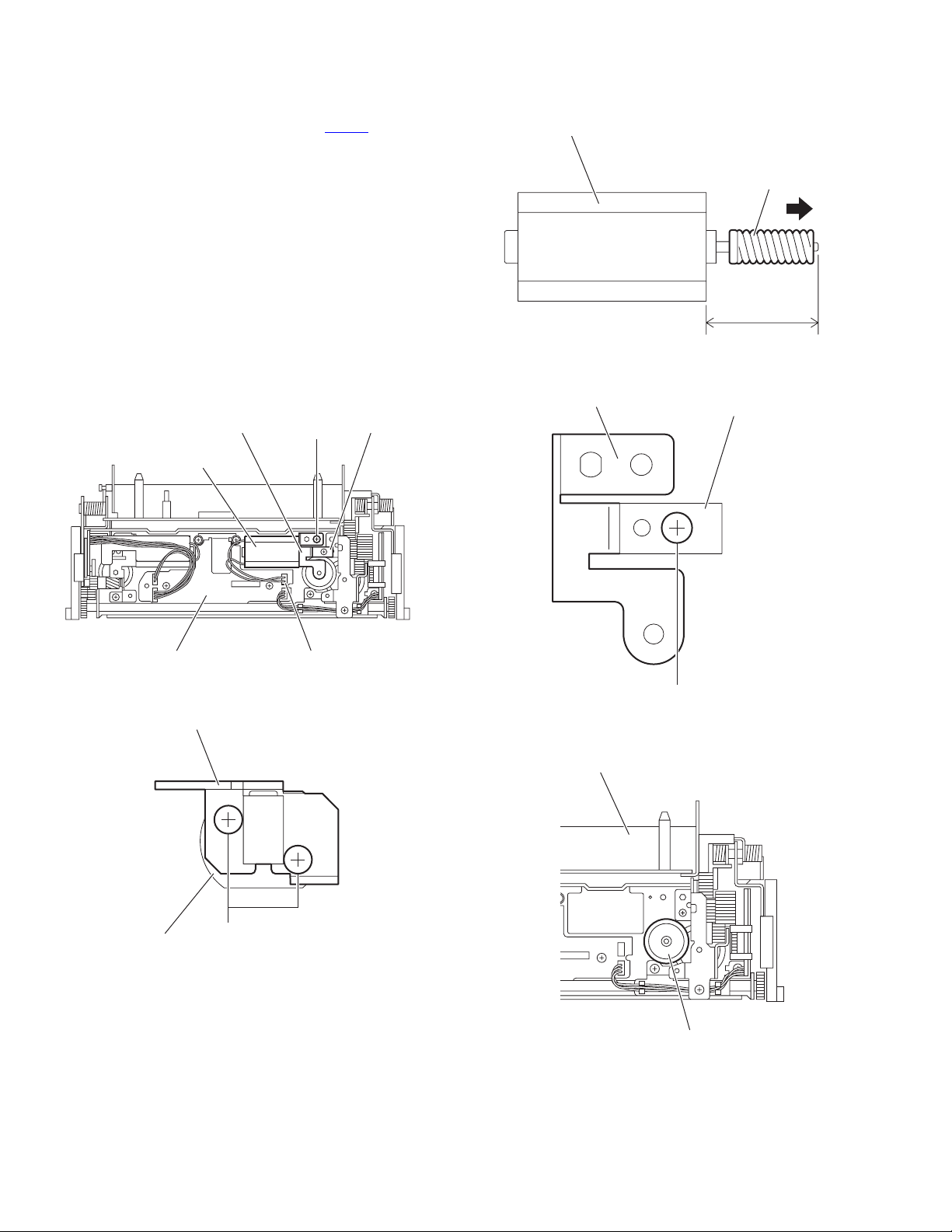
3.2.5 Removing the worm gear, motor bracket (A) and third worm
(See Figs.12 to 16)
• Remove the display drive unit and cover.
(1) Disconnect the wire from the connector CN311 on the mo-
tor board. (See Fig.12.)
(2) Remove the screw F attaching the motor bracket (A). (See
Fig.12.)
(3) Take out the motor bracket (A), worm guide and motor to-
gether. (See Fig.12.)
(4) Remove the two screws G attaching the motor and remove
the motor from the motor bracket (A). (See Fig.13.)
(5) Pull the worm gear out of the motor. (See Fig.14.)
Reference:
When inserting the warm gear in the shaft of the motor,
insert it by a measurement of a rule. (See Fig.14.)
(6) Remove the screw H attaching the worm guide to the motor
bracket (A). (See Fig.15.)
(7) From the top side of the display drive unit, pull the third
worm in an upward direction. (See Fig.16.)
Worm guideMotor bracket (A)
F
Motor
Motor
Fig.14
Motor bracket (A)
Worm gear
16 ± 0.1 (mm)
Worm guide
Motor board CN311
Fig.12
Motor bracket (A)
Motor
G
Fig.13
H
Fig.15
Display drive unit
Third worm
Fig.16
1-18 (No.MA101)
Page 19

3.2.6 Removing the second wheel and R.L.S. gear
(See Figs.17 to 24)
• Remove the display drive unit and cover.
(1) Disconnect the wire from the connector CN311
tor board. (See Fig.17.)
(2) Remove the screw J attaching the motor bracket (A). (See
Fig.17.)
(3) Take out the motor bracket (A), worm guide and motor to-
gether. (See Fig.17.)
(4) Remove the two screws K attaching the gear bracket as-
sembly. (See Fig.18.)
(5) Take out the gear bracket assembly with other parts from
the display drive unit.
(6) From the left side of the gear bracket assembly, remove the
two screws L attaching the gear bracket cover. (See
Fig.19.)
(7) Pull out the joint gear in the direction of the arrow. (See
Fig.20.)
(8) Pull out the hex gear and second wheel together in the di-
rection of the arrow. (See Fig.20.)
(9) Pull the second wheel out of the hex gear. (See Fig.21.)
(10) Pull the third gear in an upward direction. (See Fig.22.)
(11) From the top side of the display drive unit, disconnect the
wire from the connector CN331
Fig 22.)
(12) Remove the screw M attaching the R.L.S. bracket. (See
Fig.22.)
(13) Take out the R.L.S. barcket with other parts from the dis-
play drive unit. (See Fig.22.)
Reference:
When attaching the R.L.S. bracket, pass the wire
through the sections a on the wire holder as before. (See
Fig.22.)
(14) From the back side of the R.L.S. bracket, remove the screw
N attaching the R.L.S. spring to the R.L.S. barcket and remove the R.L.S. spring in the direction of the arrow. (See
Fig.23.)
Reference:
When attaching the R.L.S. spring, hang the torsion
spring (R.L.S.) on the R.L.S. spring as before. (See
Fig.23.)
(15) From the front side of the R.L.S. bracket, remove the
R.L.S. gear toward this side. (See Fig.24.)
Reference:
When attaching the R.L.S. gear, attach the torsion spring
(R.L.S.) with it as before. (See Fig.24.)
on the motor board. (See
on the mo-
Motor
Motor board CN311
Fig.17
Display drive unit K
Gear bracket assembly
Fig.18
Gear bracket assembly
Gear bracket cover
K
Worm guideMotor bracket (A)
J
L
Fig.19
(No.MA101)1-19
Page 20

Joint gear
Torsion spring (R.L.S.)
R.L.S. spring
Hex gearSecond wheel
Fig.20
Hex gear Second wheel
Fig.21
Display drive unit Third gear
R.L.S. spring
R.L.S. bracket
R.L.S. bracket
N
Fig.23
Torsion spring (R.L.S.)
R.L.S. gear
a
Motor board CN331 R.L.S. bracket
Fig.22
1-20 (No.MA101)
M
Fig.24
Page 21

3.3 Display unit section
• Remove the display unit from the main body.
(See "3.1.1 Removing the display unit".)
3.3.1 Removing the display back panel
(See Figs.1 to 3)
(1) From the both sides of the display unit, remove the six
screws A attaching the display back panel. (See Figs.1 and
2.)
(2) From the rear side of the display unit, remove the three
screws A attaching the display rear cover. (See Fig.3.)
(3) Release the joints a first and relese the joint b. (See Fig.3.)
(4) Remove the display rear cover.
Note:
When releasing the joints a and joints b, take care not to
break the claws of the display rear cover. (See Fig.3.)
(5) Remove the four screws B attaching the display back pan-
el. (See Fig.3.)
(6) Take out the display back panel from the display unit.
Display back panel
A
Fig.1
Display back panel
A
Fig.2
a
a
A
A
a
b
A
a
BB
Display rear cover
Display back panel
Fig.3
(No.MA101)1-21
Page 22

3.3.2 Removing the switch board
(See Fig.4)
• Removing the switch board (See Fig.4)
(1) Release the lock of the connector CN402 on the display
board in the direction of the arrow and disconnect the card
wire.
Reference:
After connecting the card wire, fix it with the spacer(H) as
before.
(2) Take out the switch board from the display unit.
3.3.3 Removing the display board
(See Fig.4)
• Prior to performing the following procedures, remove the dis-
play back panel.
Reference:
Remove the switch board as required.
(1) Release the lock of the connector CN402
board in the direction of the arrow and disconnect the card
wire.
(2) Release the locks of the connectors (CN421
the display board in the direction of the arrow and disconnect the flexible wire.
(3) Disconnect the wire from the connector CN471
play board.
(4) Bend the hooks c in the direction of the arrow.
(5) Remove the two screws C attaching the slider assembly.
(6) Remove the tension spring from the section d and remove
the slider assembly in the direction of the arrow 1.
(7) Remove the three screws D attaching the display board
and take out the display board from the display unit.
Reference:
After connecting the each wire, fix them with the spacer(H) as
before.
on the display
, CN451) on
on the dis-
CN451
CN421
D
c
1
Slider assembly
Display board
Spacer(H)
CN402
Spacer(H)
C
D
Slider assembly
Fig.4
Switch board
Spacer(H)
c
CN471
C
D
Tension spring
d
3.3.4 Removing the LCD module
(See Fig.5)
• Prior to performing the following procedures, remove the dis-
play back panel and display board.
Release the claws e in the direction of the arrow and take out
the LCD module from the display panel.
e
e
Display panel
LCD module
e
e
Fig.5
1-22 (No.MA101)
Page 23

3.4 DVD mechanism assembly section
3.4.1 Removing the front end board
(See Fig.1)
Caution:
Before disconnecting the flexible wire extending from the DVD
pickup, solder the short-circuit point on the flexible wire using
a grounding soldering iron.
If you do not follow this instruction, the DVD pickup may be
damaged.
(1) Turn over the body, and solder the short-circuit points on
the flexible wire extending from the DVD pickup.
(2) Disconnect the flexible wire from connector CN101
front end board.
(3) Disconnect the card wire from connector CN201 on the
front end board.
(4) Disconnect the flexible wire from connector CN202
front end board.
(5) Unsolder two soldered points a on the front end board and
remove the wire extending from the feed motor.
(6) Remove the two screws A and screw B attaching the front
end board.
Caution:
• As the flexible wire to be connected to CN101
attach it to the front end board using a double tape.
• After reassembling, unsolder the short-circuit points.
on the
on the
, make sure to
Flexible wire
Double tape
CN101
A
Short-circuit points
DVD mechanism assembly
A
Card wire
Feed motor
CN201
CN202
a
B
Front end board
Fig.1
(No.MA101)1-23
Page 24

3.4.2 Removing the top cover
(See Fig.2)
(1) Remove the two screws C attaching the top cover on the
back of the body.
(2) Remove the top cover upward.
Reference:
When reassembling, set part b of the top cover under the
bending part c of the chassis frame.
3.4.3 Removing the mechanism section
(See Figs.2 to 4)
• Remove the top cover.
(1) Remove the two screws D attaching the right and left stop-
pers on the front side. (See Fig.2.)
(2) Remove the two floating springs on the bottom of the body.
(See Fig.3.)
(3) Move the mechanism section upward and remove from the
chassis frame.
(4) The three damper springs (damper SP. (F) and damper
SP. (R)) come off from the dampers (damper(F) and damper (R)). (See Fig.4.)
Caution:
• When reassembling, reattach the damper spring to the
damper respectively and insert the three shafts on the bottom of the mechanism to the dampers.
• Before inserting the shaft to the dampers, apply IPA to the
hole of the dampers.
Floating spring
Fig.3
Mechanism section
Top cover
DVD mechanism assembly
Stopper
D
Stopper
D
Fig.2
C
c
Chassis frame
Damper SP. (F)
(Silver)
C
b
Damper (F)
(Black)
Damper SP. (F)
(Silver)
Damper (F)
(Black)
Fig.4
Damper SP. (R)
(Red)
Damper (R)
(Purple)
Chassis frame
1-24 (No.MA101)
Page 25

3.4.4 Removing the clamper unit
(See Figs.5 to 7)
• Remove the top cover and the mechanism section.
(1) Remove the clamper2 spring on the bottom of the mecha-
nism section. (See Figs.5.and 6.)
(2) Release the part d of the clamper spring from the bending
part of the chassis base assembly. (See Fig.7.)
(3) Move the clamper unit in the direction of the arrow and turn.
Release the two joints e and f, then remove the clamper
unit upward. (See Fig.5.)
Clamper unit
g
Clamper spring
Clamper spring
Chassis base assembly
d
Fig.7
f
Clamper2 spring
Chassis base assembly
Clamper2 spring
e
Fig.5
Chassis base assembly
Clamper unit
Fig.6
(No.MA101)1-25
Page 26

3.4.5 Reattaching the clamper unit
(See Figs.5 to 9)
(1) Attach the clamper spring to the clamper unit. (See Fig.8.)
(2) Move the clamper unit to set the side joints e and f to each
boss of the chassis base assembly. Make sure that part g
is inserted to the notch of the chassis base assembly. (See
Figs.5 and 9.)
(3) Move the part d of the clamper spring to the outside of the
bending part of the chassis base assembly. (See Fig.7.)
(4) Attach the clamper2 spring to the chassis base assembly.
(See Figs.5 and 6.)
Reference:
When reattaching, temporarily hook the end of the clamper
spring as shown in the figure to make the work easy. (See
Fig.8.)
Clamper unit
Clamper spring
Clamper unit
Fig.8
Fig.9
g
Notch
1-26 (No.MA101)
Page 27

3.4.6 Removing the front unit
(See Figs.10 to 12)
• Remove the top cover and the mechanism section.
(1) Disconnect the flexible wire from connector CN202
front end board at the bottom of the body. (See Fig.10.)
(2) Remove the screw E attaching the front unit on the top of
the body. (See Figs.11 and 12.)
(3) Move the front unit toward the front to release joint h, and
release two joints i and j on the right side of the chassis
base assembly. Then remove the front unit upward. (See
Figs.11 and 12.)
(4) Remove the two screws F attaching the switch board. (See
Fig.12.)
Reference:
You can remove the switch board only without removing the
front unit.
Caution:
When reassembling, attach the flexible wire extending from
the switch board using the double tape. (See Figs.10 and 12.)
Front end board
on the
E
Front unit
h
Fig.11
CN202
Double tape
Fig.10
Flexible wire
Double tape
j
i
F
Switch board
Front unit
E
Chassis base assembly
Fig.12
h
(No.MA101)1-27
Page 28

3.4.7 Removing the loading arm assembly.
(See Figs.13 and 14)
• Remove the top cover, the mechanism section and the front
unit.
(1) From the top of the body, move the loading arm assembly.
from the front side upward, and release the bosses from
the right and left joints k and m of the chassis base assembly.
(2) Release the boss from notch n of the connect arm on the
right side of the body, and release the boss from notch p of
the slide cam assembly on the left side.
m
Loading arm assembly
Slide cam
assembly
p
m
Fig.13
Loading arm assembly
k
Chassis base assembly
k
n
n
Connect arm
1-28 (No.MA101)
Fig.14
Page 29

3.4.8 Removing the rod (L)(R)/roller assembly
(See Figs.15 and 16)
• Remove the top cover, the mechanism section, the front unit
and the loading arm assembly.
(1) Release the rod (L) and (R) from the joints q at the bottom
of the loading arm assembly. (See Fig.15.)
(2) Remove the roller assembly from the loading arm assem-
bly. (See Fig.16.)
(3) Remove the two collars and washer from the roller assem-
bly. (See Fig.16.)
Caution:
After attaching the loading arm assembly to the roller assembly, attach the rod (L) and (R). Attach the rods to the right and
left collars of the roller assembly. (See Figs.15.)
When reattaching the rod (L) and (R) to the loading arm assembly, engage each joints q as shown in Fig.15. As joints r
of the rod (L), let the rod through r before reattaching it.
Collar
Collar
Roller assembly
Rod(R) Rod(L)
q
q
Collar
Rod(L)
Rod(R)
Loading arm assembly
q
Fig.15
Roller assembly
q
r
Rod(L)
q
Collar
Washer
Rod(R)
Loading arm assembly
Fig.16
(No.MA101)1-29
Page 30

3.4.9 Removing the DVD pickup
(See Figs.17 to 19)
• Remove the front end board.
(1) From the bottom of the body, turn the feed gear in the di-
rection of the arrow to move the DVD pickup outwards.
(See Fig.17.)
(2) Remove the screw G attaching the thrust spring. (See
Fig.17.)
(3) Remove the DVD pickup assembly upward on the L.S.
gear side and release from sub shaft at joint s. Move the
lead screw of the DVD pickup assembly in the direction of
the arrow to release from joint t. (See Fig.18.)
(4) Remove the screw H attaching the rack spring/ rack plate
on the DVD pickup. (See Fig.19.)
(5) Pull out the lead screw. (See Fig.19.)
Caution:
• When releasing the lead screw, the L.S. collar comes off at
the end of the lead screw. When reassembling, reattach the
L.S. collar to the lead screw. (See Fig.19.)
• After reattaching the L.S. collar, reattach it to the point t of
the lead screw, and to the holder (M). Make sure that the
L.S. collar is set on the lod (M). (See Fig.18.)
• Perform adjustment after replacing the pickup.
Sub shaft
Holder(M)
s
t
L.S. collar
Lod(M)
Lead screw
L.S. gear
DVD mechanism assembly
Feed gear
Thrust spring
DVD pickup assembly
Fig.17
DVD pickup assembly
Fig.18
H
Rack spring
Lead screw
Rack plate
G
L.S. collar
DVD pickup
Fig.19
1-30 (No.MA101)
Page 31

3.4.10 Removing the spindle motor
(See Fig.20)
• Remove the front end board.
Remove the two screws J attaching the spindle motor on the
bottom of the body.
Caution:
Perform adjustment when reattaching the spindle motor.
DVD mechanism assembly
Spindle motor
J
Fig.20
(No.MA101)1-31
Page 32

3.4.11 Removing the feed motor assembly
r
(See Figs.21 and 22)
• Remove the front end board.
(1) Remove the feed TRI. spring on the bottom of the body.
(See Fig.21.)
(2) Remove the two screws K attaching the feed motor assem-
bly. (See Fig.21.)
(3) Remove the slit washer from the motor H. assembly and
pull out the worm wheel. (See Fig.22.)
(4) Remove the two screws L attaching the feed motor. (See
Fig.22.)
Feed TRI. spring
Slit washer
K
Feed motor assembly
Fig.21
Worm wheel
L
Motor H. assembly
Feed moto
Fig.22
1-32 (No.MA101)
Page 33

3.5 Hideaway unit section
3.5.1 Removing the top chassis
(See Figs.11 to 3)
(1) From the both sides of the main body, remove the four
screws A attaching the top chassis. (See Fig.1 and 2.)
(2) From the front side of the main body, remove the three
screws A, screw B and four screws C attaching the top
chassis. (See Fig.3.)
(3) Take out the top chassis from the main body in the direction
of the arrow. (See Figs.1 to 3.)
Top chassis
A
Fig.1
Top chassis
A
3.5.2 Removing the DSP board
(See Fig.4)
• Prior to performing the following procedures, remove the top
chassis.
(1) Remove the four screws D attaching the DSP board.
(2) Disconnect the connector CN901
board.
from the hideaway
Top chassis
CN901
A ACB
Fig.2
A
Fig.3
D
DSP board
Fig.4
Hideaway board
D
(No.MA101)1-33
Page 34

3.5.3 Removing the hideaway board
(See Figs.5 and 6)
• Prior to performing the following procedures, remove the top
chassis and DSP board.
(1) From the rear side of the main body, remove the four
screws E attaching the hideaway board. (See Fig.5.)
(2) From the top side of the main body, disconnect the wire
from the connector CN601
Fig.6.)
Reference:
After connecting the wire to the connector CN601
with the wire holder as before. (See Fig.6.)
(3) Remove the three screws F attaching the hideaway board.
(See Fig.6.)
(4) Take out the hideaway board from the bottom chassis as-
sembly.
on the hideaway board. (See
, fix it
E
Fig.5
CN601
Hideaway boardWire holder
Fig.6
F
1-34 (No.MA101)
Page 35

SECTION 4
ADJUSTMENT
4.1 Adjustment method
4.1.1 Test instruments required for adjustment
(1) Digital oscilloscope (100MHz)
(2) Jitter meter
(3) Digital tester
(4) Digital multi meter (For voltage measurement)
(5) Electric voltmeter
(6) Frequency counter
(7) Tracking offset meter
(8) Test Disc : VT501 or VT502
(9) Extension studs : STDV001-3P
(10) Extension cable : EXTAV70X-50PF
4.1.3 Connection method
When confirming the mechanism movement, connect each unit shown in Fig.1.
Connection procedure
(1) Connect the front panel assembly to the main board.
(2) Attach the extension studs to the DVD mechanism assembly.
(3) Connect the DVD mechanism assembly and the main board with a extension cable.
(4) Connect the hideaway unit and the main board with an attached cable.
(5) Fix the mechanism cover with tape in the top drive unit.
(6) Hang the mechanism cover on the rear bracket.
(7) Spread the wooden boards under the top drive unit in order to put it up shown in Fig.1.
(8) Attach the display unit to the top drive unit.
4.1.2 Standard measuring conditions
Power supply voltage DC14.4V(11 to 16V)
Load impedance 4Ω(2 Speakers connection)
Line output 20kΩ
Caution:
Be sure to attach the heat sink and rear bracket onto the power
amplifier IC and regulator IC respectively, before supply the
power. If voltage is applied without attaching these parts, the
power amplifier IC and regulator IC will be destroyed by heat.
(No.MA101)1-35
Page 36

4.1.4 Connecting diagram of extension cable
Fix it with tape.
Fix it with tape.
Extension cable
EXTAV70X-50PF
Fix it in a slit.
Monitor stability base
Example : Wood panel
(200mm x 170mm x 15mm)
Extension stud
STDV001-3P
Fig.1
1-36 (No.MA101)
Page 37

4.1.5 Adjustment method for jitter
After replacing the pickup, set the unit in the service mode to display a jitter value on the LCD. Confirm that the jitter value measured
with a jitter meter is within 12.0% of the jitter value displayed on the LCD. If it is within 12.0%, then adjustment is not necessary.
If the measured jitter value is outside the 12.0% tolerance range, perform the following adjustments.
4.1.5.1 Adjustment procedure
(1) Connect each unit shown in Fig.1.
(2) Set the unit to the service mode and display a jitter value (hex data) on the LCD.
(3) Turn each of the screws a, b and c, by a half-turn per step, in the direction that reduces the jitter value in order to minimize it.
(Do not turn a screw more than a half turn at a time, but adjust the screws in the cycle of a → b → c → a.)
(4) After completing the adjustment, secure the screws with screw lock paint.
c
b
a
Jitter value adjustment procedure (Pickup horizontal level adjustment relative to the DVD recording surface)(For the adjustment tool
use a 3 mm wrench and not a screwdriver, this procedure will make the adjustment easier.)
3 mm wrench
(No.MA101)1-37
Page 38

4.1.6 Jitter value conversion table
Load the test disc and set the unit to the service mode. A jitter value converted to the hex value is displayed on the LCD. Refer to the
corresponding decimal notation value shown in the following Jitter Conversion Table.
The adjustment is OK if the jitter value measured with a jitter meter is within 12.0% of the jitter value displayed on the LCD.
If the measured jitter value is outside the 12.0% tolerance range, adjust it to minimize the difference between the measured value and
the displayed value.
Indicated
on the LCD
20A7
2072
203D
2008
1FD2
1F9D
1F68
1F33
1EFE
1EC8
1E93
1E5E
1E29
1DF4
1DBE
1D89
1D54
1D1F
1CEA
1CB4
1C7F
1C4A
1C15
1BE0
1BAA
1B75
1B40
1B0B
1AD6
1AA0
1A6B
1A36
1A01
19CC
1996
1961
192C
18F7
JIT OUT
1957.98
1955.32
1952.66
1950
1947.34
1944.68
1942.02
1939.36
1936.7
1934.04
1931.38
1928.72
1926.06
1923.4
1920.74
1918.08
1915.42
1912.76
1910.1
1907.44
1904.78
1902.12
1899.46
1896.8
1894.14
1891.48
1888.82
1886.16
1883.5
1880.84
1878.18
1875.52
1872.86
1870.2
1867.54
1864.88
1862.22
1859.56
Jitter value
(%)
3818
4.7
3825
4.8
3832
4.9
3840
5.0
384D
5.1
385A
5.2
3867
5.3
3875
5.4
3882
5.5
388F
5.6
389D
5.7
38AA
5.8
38B7
5.9
38C5
6.0
38D2
6.1
38DF
6.2
38EC
6.3
38FA
6.4
3907
6.5
3914
6.6
3922
6.7
392F
6.8
393C
6.9
394A
7.0
3957
7.1
3964
7.2
3971
7.3
397F
7.4
398C
7.5
3999
7.6
39A7
7.7
39B4
7.8
39C1
7.9
39CF
8.0
39DC
8.1
39E9
8.2
39F6
8.3
3A04
8.4
Indicated
on the LCD
18C2
188C
1857
1822
17ED
17B8
1782
174D
1718
16E3
16AE
1678
1643
160E
15D9
15A4
156E
1539
1504
14CF
149A
1464
142F
13FA
13C5
1390
135A
1325
12F0
12BB
1286
1250
121B
11E6
11B1
117C
1146
1111
JIT OUT
1856.9
1854.24
1851.58
1848.92
1846.26
1843.6
1840.94
1838.28
1835.62
1832.96
1830.3
1827.64
1824.98
1822.32
1819.66
1817
1814.34
1811.68
1809.02
1806.36
1803.7
1801.04
1798.38
1795.72
1793.06
1790.4
1787.74
1785.08
1782.42
1779.76
1777.1
1774.44
1771.78
1769.12
1766.46
1763.8
1761.14
1758.48
Jitter value
(%)
3A11
8.5
3A1E
8.6
3A2C
8.7
3A39
8.8
3A46
8.9
3A54
9.0
3A61
9.1
3A6E
9.2
3A7B
9.3
3A89
9.4
3A96
9.5
3AA3
9.6
3AB1
9.7
3ABE
9.8
3ACB
9.9
3AD9
10.0
3AE6
10.1
3AF3
10.2
10.3
10.4
10.5
10.6
10.7
10.8
10.9
11.0
11.1
11.2
11.3
11.4
11.5
11.6
11.7
11.8
11.9
12.0
12.1
12.2
3B00
3B0E
3B1B
3B28
3B36
3B43
3B50
3B5E
3B6B
3B78
3B85
3B93
3BA0
3BAD
3BBB
3BC8
3BD5
3BE3
3BF0
3BFD
Indicated
on the LCD
10DC
10A7
1072
103C
1007
FD2
F9D
F68
F32
EFD
EC8
E93
E5E
E28
DF3
DBE
D89
D54
D1E
CE9
CB4
C7F
C4A
C14
BDF
BAA
B75
B40
B0A
AD5
AA0
A6B
A36
A00
9CB
996
961
92C
JIT OUT
1755.82
1753.16
1750.5
1747.84
1745.18
1742.52
1739.86
1737.2
1734.54
1731.88
1729.22
1726.56
1723.9
1721.24
1718.58
1715.92
1713.26
1710.6
1707.94
1705.28
1702.62
1699.96
1697.3
1694.64
1691.98
1689.32
1686.66
1684
1681.34
1678.68
1676.02
1673.36
1670.7
1668.04
1665.38
1662.72
1660.06
1657.4
Jitter value
(%)
12.3
3C0A
12.4
3C18
12.5
3C25
12.6
3C32
12.7
3C40
12.8
3C4D
12.9
3C5A
13.0
3C68
13.1
3C75
13.2
3C82
13.3
3C8F
13.4
3C9D
13.5
3CAA
13.6
3CB7
13.7
3CC5
13.8
3CD2
13.9
3CDF
14.0
3CED
14.1
3CFA
14.2
3D07
14.3
3D14
14.4
3D22
14.5
3D2F
14.6
3D3C
14.7
3D4A
14.8
3D57
3D64
14.9
3D72
15.0
3D7F
15.1
3D8C
15.2
3D99
15.3
3DA7
15.4
3DB4
15.5
3DC1
15.6
3DCF
15.7
3DDC
15.8
3DE9
15.9
3DF7
16.0
Calculation
1-38 (No.MA101)
Indicated on the LCD JIT OUT Jitter (%)
1AD6 1883.5 7.5
Page 39

4.1.7 Monitor adjustment
Procedure:
(1) Install a monitor to the main unit in the state that took off a display back panel.
(2) Switch on the main unit.
(3) According to the following chart, perform each adjustment.
Item Adjustment points Adjustment volume Adjustment value
Free Run Frequency adjustment
Touch Panel Sensor adjustment
Touch Panel Sensor adjustment
Touch Panel Sensor adjustment
Touch Panel Sensor adjustment
Screen right and left adjustment
TP431
TP425
TP426
TP427
TP428
Monitor screen
VR451
VR426
VR428
VR423
VR425
VR441
15.73kHz
DC1.1V㨪DV1.4V
DC1.1V㨪DV1.4V
DC1.1V㨪DV1.4V
DC1.1V㨪DV1.4V
Adjust it so that right and left position
becomes it centrally.
(No.MA101)1-39
Page 40

4.2 Service mode
4.2.1 Jigs and test instruments
(1) Test disc: VT-501, VT-502
(2) NTSC signal generator (E version only)
4.2.2 Standard input/output conditions
Power supply voltage: C14.4V (11V to 16V)
Load impedance: 4 Ω (2 Speakers connection)
Line output: 20k Ω
4.2.3 Service mode setting procedure
(The DVD does not need to be loaded before starting the following procedure.)
POWER/ATT
MODE
NEXT
PEVIOUS
1. Press a [POWER/ATT] button on a main unit and switch it on.
2. Press the [NEXT ] button and [PREVIOUS ] button simultaneously while pressing the [POWER/ATT]
button on the main unit.
3. This unit is set by a service mode and a service menu is displayed on the monitor..
Exchanging it operate a menu of a service mode with the [NEXT ] button and [PREVIOUS ] button.
Operate choice of a menu with a [MODE] button.
4. The indication of monitor return to the normal menu by pressing the [POWER/ATT] button on the main unit.
1-40 (No.MA101)
Page 41

4.2.4 Service mode menu
MENU AREA/REGION : Indication of destination and region
Service Mode Menu
MONITOR
TOUCH PANEL TEST
TOUCH PANEL CALIBRATION
AREA / REGION
VERSION
RUNNING MODE
CHECK MODE
EXPERT MODE
[NEXT] : UP [PREV] : DW [MODE] : ENT
This menu scrolls it with the [NEXT ]/[PREVIOUS ]
buttons.
AREA / REGION
HIDE - AREA
B / E - AREA
B / E - REGION
[MODE]
aa
Destination of hideaway
bb
Destination of DVD unit
cc
Region of DVD unit
(Note)
REGION CHANGE not using it by service.
VERSION : Indication of microcomputer version
VERSION
SYS - VER
F / E - VER
B / E - VER
SDK - VER
GUI - VER
MONITOR - VER
HIDE - VER
TV - VER
CDCH - VER
aaaa aa
bb
cc
dddddddddddddd
eeee
gggg
hhhh
kkkk
nnnn
: aa
: bb
: cc
: REGION CHANGE
: aaaa aa
: bb
: cc
: dddddddddddddd
: eeee
: gggg
: hhhh
: kkkk
: nnnn
System control microcomputer version
and ROM correction version
Front end microcomputer version
Back end microcomputer version
DVD back end SKD version
GUI version
Monitor version
Hideaway version
TV tuner version (In connection)
CD changer version (In connection)
RUNNING MODE (For use in various running tests)
(Note)
This mode not using it by service.
CHECK MODE : Check mode for DVD unit
CHECK MODE
CURRENT
JITTER
EJECT
CLOSE
NOMAL PLAY
OUT - TRACKING OFF
IN - TRACKING OFF
CD - LASER ON
[NEXT] : UP [PREV] : DW [MODE] : ENT
This menu scrolls it with the [NEXT ]/[PREVIOUS ] buttons.
A thing without CURRENT/JITTER indication is space.
See "5.1.5 DVD unit check mode" for details.
EXPERT MODE (DVD unit expert mode)
(Note)
This mode not using it by service.
TEMPERATURE : Data in the temperature sensor in the system controller/hideaway
is read every 5 seconds and displayed in hex numbers.
A
:
:
(No.MA101)1-41
Page 42

A
READ ERROR : Indication of an error history
LOADING/EJECT mechanism error
Monitor mechanism error
Changer error
"TOTAL ERROR :zzzzzz"
"E-n :xxyyyy"
"E0n :xxyyyy"
CLEAR ERROR : Clear error history
See "5.1.7 Error code table" for details.
Total error count
(A figure between 0 and 999999 is displayed.
1000000 or more is also displayed as 999999.)
(First five error codes)
Detailed error code
Error code
Counter
(Latest three error codes)
Detailed error code
Error code
Counter
The error history (LOADING/EJECT mechanism,
monitor mechanism and changer) is cleared.
The error history stored in the EEPROM is cleared.
(by writing 00h)
"COMPLETE" is displayed by a monitor after clear
was finished.
INITIALIZE : Initialize user set data
The system controller EEPROM is initialized except for the
error history.
INITIALIZE ALL : Initialize all data to the factory setting
The system controller EEPROM is initialized entirely.
MEMORY CHECK : Check indication is done with a normal screen.
MONITOR : Monitor service mode
MONITOR MECHA CHECK : Check mode of a monitor mechanism
DEMO SET UP : Change of a demonstration mode is done.
Touch Panel Test : GUI is set in the touch panel test mode
(Note)
This mode not using it by service.
See "5.1.8 Monitor adjustment" for details.
(Note)
This mode not using it by service.
Confirmation of a position gap of touch panel
Cancellation of this mode do long push of the
[POWER/ATT] button.
1-42 (No.MA101)
B
Page 43

B
4.2.5 DVD unit check mode
Touch Panel Calibration : Touch panel proofreading mode
81h 82h 83h
TOUCH PANEL CALIBRATION CODE 8Dh
84h 85h 86h
87h 88h 89h
See "5.1.11 Touch panel manual operation proofreading procedure" for details.
Push with a finger from 81h in turn.
After the proofreading end, push the [PREVIOUS ] button in order to switch
off the panel.
An effective key in a proofreading mode
[NEXT ]
[PREVIOUS ]
[POWER/ATT]
: 1. Monitor power supply ON
2. Touch panel proofreading mode ON
: 1. Touch panel proofreading mode OFF
2. Monitor power supply OFF
: Power supply OFF (Proofreading mode cancellation)
No. Key
NORMAL PLAY
1
Disc startup and through playback
DVD unit operation Remark
(Playback starts from the start position)
OUT
2
Tracking off the outermost position of CD
TRACKING
IN TRACKING
3
Tracking off the innermost position of CD
OFF
CD-LASER ON
4
5
DVD-LASER
CD_LD lights and laser current is displayed
DVD_LD lights and laser current is displayed
ON
DVDx1 JITTER
6
7
8
9
10
MODE
EEPROM
DATA+
EEPROM
DATAEEPROM
DATA CLEAR
DVD-SL
DVD x1 jitter measuring mode
(for use in mechanism adjustment)
Contents of EEPROM used by mechanism
(0x00 - 0xFF) displayed (FWD)
Contents of EEPROM used by mechanism
(0x00 - 0xFF) displayed
Initialization of EEPROM contents used by
the mechanism
Search & jitter measurement of the specified
position of DVD-SL
DVD-DL
11
12
13
14
15
16
(PARALLEL)
DVD-DL
(OPPOSITE)
PLAY
STOP
EJECT
CLOSE
Search & jitter measurement of the specified
position of parallel disc of the DVD-DL
Search & jitter measurement of the specified
position of opposite disc of DVD-DL
Disc playback
Disc stopped & LD-OFF
OPEN
CLOSE
Indication is displayed in hex numbers.
The check mode can be exited by pressing the [POWER] key.
For EF phase error
For EF phase error
: Laser current value
: Jitter value
: Laser current value
: Jitter value
: Laser current value
: Jitter value
: EEPROM address
: EEPROM contents
: EEPROM address
: EEPROM contents
: 0x00-0x02
(Position measured with VT-502)
: Jitter value
: 0x00-0x06
(Position measured with VT-501)
: Jitter value
: 0x00-0x06
(Position measured with VT-501)
: Jitter value
: Laser current value
: Jitter value
(No.MA101)1-43
Page 44

4.2.6 Error code table
(1) Error code table of LOADING/EJECT mechanism error
Error code (1 byte) Detailed error codes (2 bytes)
First byte [01] Eject error
[09] Loading error
Route No. (EJECT route No.)
-
1(2)
1(2)
First byte
Second byte
(Example) When a switch status error occurs during loading route 3 and the
switch status is L/L/H/H/H (00111B = 07H), the error code and
detailed error code become: [09 3207].
SW1/2/3/4
1,1,1,1
0,1,1,1
0,0,1,1
Higher 4 bits
Lower 4 bits
bit7
bit6,5
bit4
bit3
bit2
bit1
bit0
[Rest SW]
[0]
[0]
[0]
Route No. (Process of error occurrence)
Refer to charts 1.1 and 1.2.
Error type
[1] Time out
[2] Switch status defectiveness
[3] Swinging error
Disc type (0: 12 cm. 1: 8 cm)
Fixed at 0
SW1 status
SW2 status
SW3 status
SW4 status
REST SW status
Loading
No Disc
Disc insert
detection
Eject
No Disc
Eject
completion
Reload
Disc push in
2(2)
2(2)
2(2)
2(2)
3(1)
3(1)
Route No. (EJECT route No.)
-
1(2)
1(2)
2(2)
2(2)
3(1)
3(1)
Transition in the center loading (Similar to 12cm in the side loading)
0,0,0,1
0,0,1,1
0,1,1,1
1,1,1,1
1,1,1,0
1,1,1,0
Chart 1.1 12cm Disc switch status transition
SW1/2/3/4
1,1,1,1
0,1,1,1
0,0,1,1
0,1,1,1
1,1,1,1
1,1,1,0
1,1,1,0
Chart 1.2 8cm Disc switch status transition
[0]
[0]
[0]
[0]
[0]
[1]
[Rest SW]
[0]
[0]
[0]
[0]
[0]
[0]
[1]
Load completion
Loading
No Disc
Disc insert
detection
Load completion
Eject start
Eject
No Disc
Eject
completion
Eject start
Reload start
Load completion
Reload
Disc push in
Reload start
Load completion
1-44 (No.MA101)
Page 45

(2) Error code table of monitor mechanism error
Error code (1 byte)
Detailed error codes (2 bytes)
First byte [01] CLOSE error
[09] OPEN error
[0A] SLIDE error
(3) Error code table of changer
Outbreak condition
Tray extension
error
Tray retraction
error
Lifter raise
error
Lifter lower
error
Chuck error PLAY position time out
Unchuck error WAIT position time out
Eject error EJECT position time out
Initialize error Mechanism switch time out
Tray-in switch time out
(Tray-in switch Low,Tray-out switch High)
Tray-out switch time out
(Tray-in switch High,Tray-out switch High)
Tray-in switch time out
(Tray-in switch Low,Tray-out switch Low)
MAG-in switch Low to high
Tray-in switch time out
(Tray-in switch High,Tray-out switch Low)
Tray-out switch time out
(Tray-in switch High,Tray-out switch High)
Tray-in switch time out
(Tray-in switch Low,Tray-out switch Low)
MAG-in switch Low to high
WAIT position time out
WAIT position time out
WAIT position time out
WAIT position time out
WAIT position time out
WAIT position time out
PLAY position time out
PLAY position time out
WAIT position time out
WAIT position time out
EJECT position time out
MAG-in switch time out
Absolute position time out
First byte
Second byte
Higher 4 bits
Lower 4 bits
Higher 4 bits
Lower 4 bits
Tray motor does not work
Tray stops on the way
NG of Tray-in SW or other defect
Magazine removed when tray partly extend
Tray motor does not work
Tray stops on the way
NG of Tray-in SW or other defect
Magazine removed when tray partly extend
Position motor does not work
Position not stable in fine adjust mode
Other fault
Position motor does not work
Position not stable in fine adjust mode
Other fault
Position motor does not work
Position not stable in fine adjust mode
Other fault
Position motor does not work
Position not stable in fine adjust mode
Other fault
Position motor does not work
Eject position not attained
Magazine not ejected
Both Tray-in and Tray-out Low
Not stable at absolute position
Route No. (Process of error occurrence)
Error type
[1] Time out
[2] Pulse nothing
[3] Angle change nothing
[4] Switch status defectiveness
Motor status
(Motor output status in an error)
Bit7
Bit6
Bit5
Bit4
SW status
Bit3
Bit2
Bit1
Bit0
Details
0=Off/1=On
0=Slide/1=Angle
0=Minus/1=Plus
Fixed at 0
MO_DET
ANGSW
CLSW
Error
code
03
03
03
03
03
03
03
03
02
02
02
02
02
02
02
02
02
02
02
02
02
02
02
03
03
Detailed
error code
0011
0012
0013
0014
0016
0017
0018
0019
0021
0022
0023
0026
0027
0028
0031
0032
0033
0036
0037
0038
0041
0042
0043
0046
0047
(No.MA101)1-45
Page 46

4.2.7 Monitor adjustment (For J version)
1. Switch on the main unit and insert a test disc (VT-501 or VT-502).
Play a 3TR(100% color bar) of the test disc and pause it.
2. In a state of procedure 1, set the main unit in a service mode. (See "5.1.3 Service mode setting procedure".)
3. Color bar is displayed to the monitor by pushing [MODE] button after having done select of [MONITOR] of the
service menu with the [NEXT ] or [PREVIOUS ] buttons, and the following indication goes in mini-LCD of
the main unit.
CHROMA
PORT
[NEXT ] button
or
[PREVIOUS ] button
INIT
CCFL
Color adjustment
-------(EEPROM data read/write of a monitor microcomputer)
Port output setting (This mode not using it by service.)
--------
Monitor microcomputer shipment initialization setting
-------(This mode not using it by service.)
Backlight brightness setting (Fixed value B3)
--------
4. Select [CHROMA] and press the [MODE] button.
An address value and data value are displayed on the mini-LCD. (0 )
Press the center of the monitor to turn off the GUI screen.
5. Change data of each address with the [VOL+]/[VOL -] button while observing the color bar (Data value flashes
on and off in change operation.) and press the [MODE] button in order to write in data. (Adjust the fixed value
in the value of a following table. Besides it, set it in reference value and make a fine adjustment while observing
the monitor.)
No.
1
2
3
4
5
6
7
8
9
10
11
12
13
14
15
16
Address
Chrominance data
0
INPUT MODE/SW
1
PICTURE
2
COLOR
3
PHASE
4
CONTRAST
5
BRIGHT
6
GAMMA 0
7
GAMMA 1
8
OUT LIMIT
9
RGB AMPLITUDE
A
SUB-BRIGHT R
B
SUB-BRIGHT B
C
COM AMPLITUDE
D
COM BLANK LEV
E
DAC OUT
F
TINT
Minimum value
00
00
00
00
00
00
00
00
00
00
00
00
00
00
00
00
Maximum value
3F
FF
3F
FF
FF
FF
FF
FF
1F
FF
FF
FF
FF
1F
FF
FF
Fixed value Reference value
1C
2F
66
22
50
A5
3A
08
1F
7C
7F
60
D2
11
86
87
Cancellation of a test mode
Push the [STANDBY] key on the main unit.
1-46 (No.MA101)
Page 47

4.2.8 Monitor adjustment (For A/U version)
1. Switch on the main unit.
Press [FUNCTION] on the monitor and press [SETUP] next.
Select [DVD MENU] and selcct [PAL] of the [COLOR SYSTEM].
2. Insert a test disc (VT-501 or VT-502).
Play a 3TR(100% color bar) of the test disc and pause it.
3. In a state of procedure 2, set the main unit in a service mode. (See "5.1.3 Service mode setting procedure".)
4. Color bar is displayed to the monitor by pushing [MODE] button after having done select of [MONITOR] of the
service menu with the [NEXT ] or [PREVIOUS ] buttons, and the following indication goes in mini-LCD of
the main unit.
Press the center of the monitor to turn off the GUI screen.
CHROMA
PORT
[NEXT ] button
or
[PREVIOUS ] button
INIT
CCFL
Color adjustment
-------(EEPROM data read/write of a monitor microcomputer)
Port output setting (This mode not using it by service.)
--------
Monitor microcomputer shipment initialization setting
-------(This mode not using it by service.)
Backlight brightness setting (Fixed value B3)
--------
5. Select [CHROMA] and press the [MODE] button.
An address value and data value are displayed on the mini-LCD. (0 )
6. Change data of each address with the [VOL+]/[VOL -] button while observing the color bar (Data value flashes
on and off in change operation.) and press the [MODE] button in order to write in data. (Adjust the fixed value
in the value of a following table. Besides it, set it in reference value and make a fine adjustment while observing
the monitor.)
7. Press the [POWER/ATT] button of the main unit, and switch it off.
8. Switch on the main unit again.
Selcct [NTSC] of the [COLOR SYSTEM].
9. Repeat the adjustment mentioned above.
10. Press the [POWER/ATT] button of the main unit and this adjustment is complete.
No.
1
2
3
4
5
6
7
8
9
10
11
12
13
14
15
16
Address
Chrominance data
0
INPUT MODE/SW
1
PICTURE
2
COLOR
3
PHASE
4
CONTRAST
5
BRIGHT
6
GAMMA 0
7
GAMMA 1
8
OUT LIMIT
9
RGB AMPLITUDE
A
SUB-BRIGHT R
B
SUB-BRIGHT B
C
COM AMPLITUDE
D
COM BLANK LEV
E
DAC OUT
F
TINT
Minimum value
00
00
00
00
00
00
00
00
00
00
00
00
00
00
00
00
Cancellation of a test mode
Push the [STANDBY] key on the main unit.
Maximum value
3F
FF
3F
FF
FF
FF
FF
FF
1F
FF
FF
FF
FF
1F
FF
FF
Fixed value Reference value
PAL NTSC PAL NTSC
1C
2F
66
22
50
7F
60
D2
86
87
A5
3A
08
1F
7C
11
1E
2F
66
22
50
A5
3A
08
1F
7C
7F
60
D2
11
86
87
(No.MA101)1-47
Page 48

4.2.9 Monitor adjustment (For E version)
[PAL screen adjustment]
1. Switch on the main unit and insert a test disc (VT-501 or VT-502).
Play a 3TR(100% color bar) of the test disc and pause it.
2. In a state of procedure 1, set the main unit in a service mode. (See "5.1.3 Service mode setting procedure".)
3. Color bar is displayed to the monitor by pushing [MODE] button after having done select of [MONITOR] of the
service menu with the [NEXT ] or [PREVIOUS ] buttons, and the following indication goes in mini-LCD of
the main unit.
Press the center of the monitor to turn off the GUI screen.
CHROMA
PORT
[NEXT ] button
or
[PREVIOUS ] button
INIT
CCFL
--------
Color adjustment
(EEPROM data read/write of a monitor microcomputer)
--------
Port output setting (This mode not using it by service.)
--------
Monitor microcomputer shipment initialization setting
(This mode not using it by service.)
--------
Backlight brightness setting (Fixed value B3)
4. Select [CHROMA] and press the [MODE] button.
An address value and data value are displayed on the mini-LCD. (0 )
5. Change data of each address with the [VOL+]/[VOL -] button while observing the color bar (Data value flashes
on and off in change operation.) and press the [MODE] button in order to write in data. (Adjust the fixed value
in the value of a following table. Besides it, set it in reference value and make a fine adjustment while observing
the monitor.)
6. Press the [POWER/ATT] button of the main unit, and switch it off.
No.
1
2
3
4
5
6
7
8
9
10
11
12
13
14
15
16
Address
Chrominance data
0
INPUT MODE/SW
1
PICTURE
2
COLOR
3
PHASE
4
CONTRAST
5
BRIGHT
6
GAMMA 0
7
GAMMA 1
8
OUT LIMIT
9
RGB AMPLITUDE
A
SUB-BRIGHT R
B
SUB-BRIGHT B
C
COM AMPLITUDE
D
COM BLANK LEV
E
DAC OUT
F
TINT
Minimum value
00
00
00
00
00
00
00
00
00
00
00
00
00
00
00
00
Maximum value
3F
FF
3F
FF
FF
FF
FF
FF
1F
FF
FF
FF
FF
1F
FF
FF
Fixed value Reference value
1E
2F
66
22
50
A5
3A
08
1F
7C
7F
60
D2
11
86
87
Cancellation of a test mode
Push the [STANDBY] key on the main unit.
1-48 (No.MA101)
Page 49

[NTSC screen adjustment]
1. Switch on the main unit.
Input a NTSC signal into a AV1 input terminal.
(In case of a DVD player, insert the test disc VT-501 and play the 3TR.)
In the case of other sources, do color confirmation with the image.
2. In a state of procedure 1, set the main unit in a service mode. (See "5.1.3 Service mode setting procedure".)
3. Color bar is displayed to the monitor by pushing [MODE] button after having done select of [MONITOR] of the
service menu with the [NEXT ] or [PREVIOUS ] buttons, and the following indication goes in mini-LCD of
the main unit.
Press the center of the monitor to turn off the GUI screen.
CHROMA
PORT
[NEXT ] button
or
[PREVIOUS ] button
INIT
CCFL
Color adjustment
-------(EEPROM data read/write of a monitor microcomputer)
Port output setting (This mode not using it by service.)
--------
Monitor microcomputer shipment initialization setting
-------(This mode not using it by service.)
Backlight brightness setting (Fixed value B3)
--------
4. Select [CHROMA] and press the [MODE] button.
An address value and data value are displayed on the mini-LCD. (0 )
5. Change data of each address with the [VOL+]/[VOL -] button while observing the color bar (Data value flashes
on and off in change operation.) and press the [MODE] button in order to write in data. (Adjust the fixed value
in the value of a following table. Besides it, set it in reference value and make a fine adjustment while observing
the monitor.)
6. Press the [POWER/ATT] button of the main unit, and switch it off.
No.
1
2
3
4
5
6
7
8
9
10
11
12
13
14
15
16
Address
Chrominance data
0
INPUT MODE/SW
1
PICTURE
2
COLOR
3
PHASE
4
CONTRAST
5
BRIGHT
6
GAMMA 0
7
GAMMA 1
8
OUT LIMIT
9
RGB AMPLITUDE
A
SUB-BRIGHT R
B
SUB-BRIGHT B
C
COM AMPLITUDE
D
COM BLANK LEV
E
DAC OUT
F
TINT
Minimum value
00
00
00
00
00
00
00
00
00
00
00
00
00
00
00
00
Maximum value
3F
FF
3F
FF
FF
FF
FF
FF
1F
FF
FF
FF
FF
1F
FF
FF
Fixed value Reference value
1C
2F
66
22
50
A5
3A
08
1F
7C
7F
60
D2
11
86
87
Cancellation of a test mode
Push the [STANDBY] key on the main unit.
(No.MA101)1-49
Page 50

4.2.10 Touch panel manual operation proofreading procedure
Procedure 1 Proofreading
(1) Set the main unit in a touch panel proofreading mode.
(2) Push the center of the figure of a cross in a circle of green (81h to 89h) on the panel in turn.
a) Push for each 3 points of the upper part of 81h and 82h and 83h with a thumb of the right hand (or, left hand) on the
panel from a direction.
b) Push 84h with a thumb of the left hand from the left course.
c) Push 85h with the middle finger of the right hand or the middle finger of the left hand from center direction.
d) Push 86h with a thumb of the right hand from the right course.
e) Push for each 3 points of the lower part of 87h and 88h and 89h with a thumb of the right hand (or, left hand) under the
panel from a direction.
(3) When proofreading was completed normally, OK is displayed.
(4) Repeat since a beginning when NG was displayed.
(5) After proofreading completion, turn off the power supply and confirm it again.
Procedure 2 Confirmation
(1) Switch on the main unit and turn the main unit into normal movement.
(2) Push a screen key of GUI and set the main unit in the mode that "NAME" is displayed in the right bottom.
(3) Push "NAME" in order to let a screen display a keyboard of British number and push all keys in order to confirm misrecognition.
(4) When misrecognition occurred, proofread it since a beginning.
1-50 (No.MA101)
Page 51

SECTION 5
TROUBLESHOOTING
5.1 AV bus cable between main unit and hideaway unit
20
16
12
6
17
13
20
16
12
7
1
QAM0612-002 6000 mm
QAM0612-001 2500 mm
6
17
13
7
1
10
1
2
3
4
5
6
7
8
9
RESET
P-ON
SDI
SDO
GND
HPAL
SPDIF
NC
DVDAR-GND
DVDAL-GND
Black
White
Light green
Brown
Yellow
Blue
Natural
Orange
Black(Tube)
Black(Tube)
11
12
13
14
15
16
17
18
19
20
NC
HPA-GND
SPDIFGND
DVDAR
DVDAL
HPAR
VIDEO-OUT
VIDEO-GND
VIDEO-IN
VIDEO-GND
Pink
Black(Tube)
Black(Tube)
Red
Green
Purple
Natural
Black(Tube)
Natural
Black(Tube)
(No.MA101)1-51
Page 52

5.2 Center speaker / rear camera cord
3
BK
BK/WH
4
1 VI/WH
3 BK
4 BK/WH
5.3 Extention aerial cord
PLUG
VI/WH
1
2
NC
BK
VI
2500 mm
BLACK
VIOLET
WH
WHITE
BACK
CAMERA
CENTER
JACK
2593 mm
1-52 (No.MA101)
Page 53

5.4 Power cord for main unit (for KD-AV7001E,KD-AV7001EU)
4 BK
5
OR/WH
EARTH
6
1 YL
4 BK
2 RD
1 YL
2 RD
CORE
3
Fuse 250V-6.3A
F6.3A
BK
BL
WH
Black
Blue
White
MEMORY
GND
ACC
RD
YL
Red
Yellow
BL/WH
5
OR/WH
6
7 RD
8 BK
1 NC
2 BR
3 NC
4 YL
4 YL
8 BK
7 RD
5 OR/WH
3 CORE
6 EARTH
GY
MEMORY
GND
ACC
ILL
REMOTE
TEL
ILL
REMOTE
TEL
O.E.REMOTE
ILLUMINATION
CONTROL
REMOTE
OUT
TEL MUTING
Memory back up battery+
Ground
ACC line
Illumination control
Remote out
Telephone muting
6 OR/WH
5 BL/WH
2 BR
O.E.REMOTE
(No.MA101)1-53
Page 54

5.5 Power cord for Hideaway unit (for KD-AV7001E,KD-AV7001EU)
1 BK
3 BL/WH
5 VI
6 VI/BK
7 GN/BK
8 GN
9 WH
10 WH/BK
11 GY/BK
12 GY
13 BR
16 YL
14 L.GN
8 GN
GN/BK
7
VI/WH
6
5 VI
4 NC
3
BL/WH
2 NC
1 BK
1000 mm
9 WH
10
WH/BK
GY/BK
11
12 GY
13 BR
14 L.GN
15 NC
16 YL
GND
GROUND
REMOTE
TEL
MEMORY
PARKING
RR+
RR-
RL-
RL+
FL+
FL-
FR-
FR+
BK
BL
WH
L.GN
2500 mm
Black
Blue
White
Light Green
GN
VI
GY
YL
BR
Green
Violet
Gray
Yellow
Brown
1 VI
3 GY
5 WH
7 GN
REMOTE
OUT
ޓTEL
MUTING
PARKING
BRAKE
1 VI
2 VI/BK
8 GN/BK
7 GN
5 WH
6 WH/BK
4 GY/BK
3 GY
2
4
6
8
VI/WH
GY/BK
WH/BK
GN/BK
POWER LEAD/
MEMORY BACK UP
4000 mm
1-54 (No.MA101)
MEMORY
GND
REMOTE
PARKING
TEL
RR
FR
RL
FL
Memory back up battery+
Ground
Remote out
Parking brake
Telephone muting
Rear Right
Front Right
Rear Left
Front Left
Page 55

5.6 Power cord for main unit (for KD-AV7000J,KD-AV7005U,KD-AV7005UN,KD-AV7008A)
4 BK
OR/WH
5
6 NC
1 YL
2 RD
4 BK
5 OR/WH
1 YL
2 RD
3 NC
BK
BL
WH
Black
Blue
White
POWER LEAD/
MEMORY BACK UP
POWER LEAD
GROUND
ILLUMINATION
CONTROL
RD
YL
Fuse 250V-6A
6A
Red
Yellow
500 mm
(No.MA101)1-55
Page 56

5.7 Power cord for hideway unit (for KD-AV7000J)
1 BK
3 BL/WH
4 BL
5 VI
6 VI/BK
7 GN/BK
8 GN
9 WH
10 WH/BK
11 GY/BK
12 GY
16 YL
14 L.GN
8 GN
GN/BK
7
VI/WH
6
5 VI
4 BL
3
BL/WH
2 NC
1 BK
9 WH
10
11
12 GY
13 NC
14 L.GN
15 NC
16 YL
1000 mm
WH/BK
GY/BK
GROUND
GND
REMOTE
ANT
RR+
RR-
RL-
RL+
FL+
FL-
FR-
FR+
MEMORY
PARKING
BK
BL
WH
L.GN
2500 mm
Black
Blue
White
Light Green
GN
VI
GY
YL
Green
Violet
Gray
Yellow
REMOTE
OUT
POWER
ANTENNA
PARKING
BRAKE
POWER LEAD/
MEMORY BACK UP
MEMORY
GND
REMOTE
PARKING
ANT
RR
FR
RL
FL
4000 mm
Memory back up battery+
Ground
Remote out
Parking brake
Power antenna
Rear Right
Front Right
Rear Left
Front Left
1-56 (No.MA101)
Page 57

5.8 Power cord for hideaway unit (for KD-AV7005U,KD-AV7005UN,KD-AV7008A)
1 BK
3 BL/WH
4 BL
5 VI
6 VI/BK
7 GN/BK
8 GN
9 WH
10 WH/BK
11 GY/BK
12 GY
13 BR
16 YL
14 L.GN
8 GN
GN/BK
7
VI/WH
6
5 VI
4 BL
3
BL/WH
2 NC
1 BK
1000 mm
9 WH
10
WH/BK
GY/BK
11
12 GY
13 BR
14 L.GN
15 NC
16 YL
GROUND
GND
REMOTE
ANT
RR+
RR-
RL-
RL+
FL+
FL-
FR-
FR+
TEL
MEMORY
PARKING
2500 mm
BK
BL
WH
L.GN
Black
Blue
White
Light Green
GN
VI
GY
YL
BR
Green
Violet
Gray
Yellow
Brown
REMOTE
OUT
POWER
ANTENNA
TEL MUTING
PARKING
BRAKE
POWER LEAD/
MEMORY BACK UP
4000 mm
MEMORY
GND
REMOTE
PARKING
TEL
ANT
RR
FR
RL
FL
Memory back up battery+
Ground
Remote out
Parking brake
Telephone muting
Power antenna
Rear Right
Front Right
Rear Left
Front Left
(No.MA101)1-57
Page 58

5.9 The initialization method of a top drive unit
(1) When top drive unit is exchanged.
(2) When exchange or gear is shifted for gear by repair of top drive unit.
(3) When Monitor Does Not Open and Close (when it Moves Manually Forcibly)
Please initialize at the above time.
Initialization procedure
TI button is detached after detaching reset button which pushes reset button, pushing TI button.
* Even if it initializes by 3., when not being repaired, repair of a top drive unit and exchange are required.
1-58 (No.MA101)
Page 59

(No.MA101)1-59
Page 60

Victor Company of Japan, Limited
AV & MULTIMEDIA COMPANY CAR ELECTRONICS CATEGORY 10-1,1chome,Ohwatari-machi,Maebashi-city,371-8543,Japan
(No.MA101)
Printed in Japan
VPT
 Loading...