

Page 1
SERVICE MANUAL
DVD RECEIVER WITH MONITOR
MA10120051
KD-AV7000,KD-AV7001,
KD-AV7005,KD-AV7008,
KV-MAV7001,KV-MAV7002
KD-AV7000
Area suffix
J ------------- Northern America
KD-AV7001
Area suffix
E ------------- Southern Europe
EU ------------------------- Turkey
KD-AV7005
Area suffix
UN --------------------------Asean
U -------------------- Other Areas
KD-AV7008
Area suffix
A ------------------------ Australia
KV-MAV7001,KV-MAV7002
Area suffix
U -------------------- Other Areas
TABLE OF CONTENTS
1 PRECAUTIONS . . . . . . . . . . . . . . . . . . . . . . . . . . . . . . . . . . . . . . . . . . . . . . . . . . . . . . . . . . . . . . . . . . . . . . . 1-4
2 SPECIFIC SERVICE INSTRUCTIONS . . . . . . . . . . . . . . . . . . . . . . . . . . . . . . . . . . . . . . . . . . . . . . . . . . . . . . 1-7
3 DISASSEMBLY . . . . . . . . . . . . . . . . . . . . . . . . . . . . . . . . . . . . . . . . . . . . . . . . . . . . . . . . . . . . . . . . . . . . . . . 1-8
4 ADJUSTMENT . . . . . . . . . . . . . . . . . . . . . . . . . . . . . . . . . . . . . . . . . . . . . . . . . . . . . . . . . . . . . . . . . . . . . . . 1-35
5 TROUBLESHOOTING . . . . . . . . . . . . . . . . . . . . . . . . . . . . . . . . . . . . . . . . . . . . . . . . . . . . . . . . . . . . . . . . . 1-51
COPYRIGHT © 2005 Victor Company of Japan, Limited
No.MA101
2005/1
Page 2
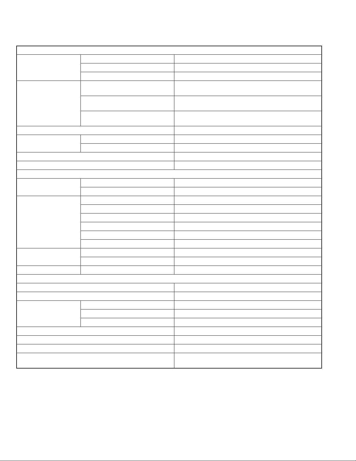
SPECIFICATION
Main unit
AUDIO AMPLIFIER SECTION
Maximum Power Output Front 50 W per channel
Rear 50 W per channel
Center 35 W
Continuous Power Output
(RMS)
Load Impedance 4 Ω (4 Ω to 8 Ω allowance)
Equalizer Control Range Frequencies 100 Hz, 300 Hz, 1 kHz, 3 kHz, 10 kHz
Frequency Response 40 Hz to 20 000 Hz
Signal-to-Noise Ratio 70 dB
Frequency Range FM 87.5 MHz to 107.9 MHz
FM Tuner Usable Sensitivity 11.3 dBf (1.0 µV/75 Ω)
AM Tuner Sensitivity 20 µV
LW Tuner Selectivity 50 µV (KV7001 only)
Signal Detection System Non-contact optical pickup (semiconductor laser)
Number of channels 2 channels (stereo)
Frequency Response DVD, fs=48 kHz 16 Hz to 22 000 Hz
Dynamic Range 96 dB
Signal-to-Noise Ratio 98 dB
Wow and Flutter Less than measurable limit
MP3 Recording Format MPEG 1/2 Audio Layer 3
Front 19 W per channel into 4 Ω, 40 Hz to 20 000 Hz at no more than
0.8% total harmonic distortion.
Rear 19 W per channel into 4 Ω, 40 Hz to 20 000 Hz at no more than
0.8% total harmonic distortion.
Center 15 W into 4 Ω, 40 Hz to 20 000 Hz at no more than 0.8% total
harmonic distortion.
Level ±10 dB
TUNER SECTION
AM 530 kHz to 1 710 kHz
50 dB Quieting Sensitivity 16.3 dBf (1.8 µV/75 Ω)
Alternate Channel Selectivity (400 kHz) 65 dB
Frequency Response 40 Hz to 15 000 Hz
Stereo Separation 35 dB
Capture Ratio 1.5 dB
Selectivity 35 dB
DVD/CD PLAYER SECTION
DVD, fs=96 kHz 16 Hz to 44 000 Hz
VCD, CD, MP3 16 Hz to 20 000 Hz
Max. Bit rate: 320 kbps
1-2 (No.MA101)
Page 3
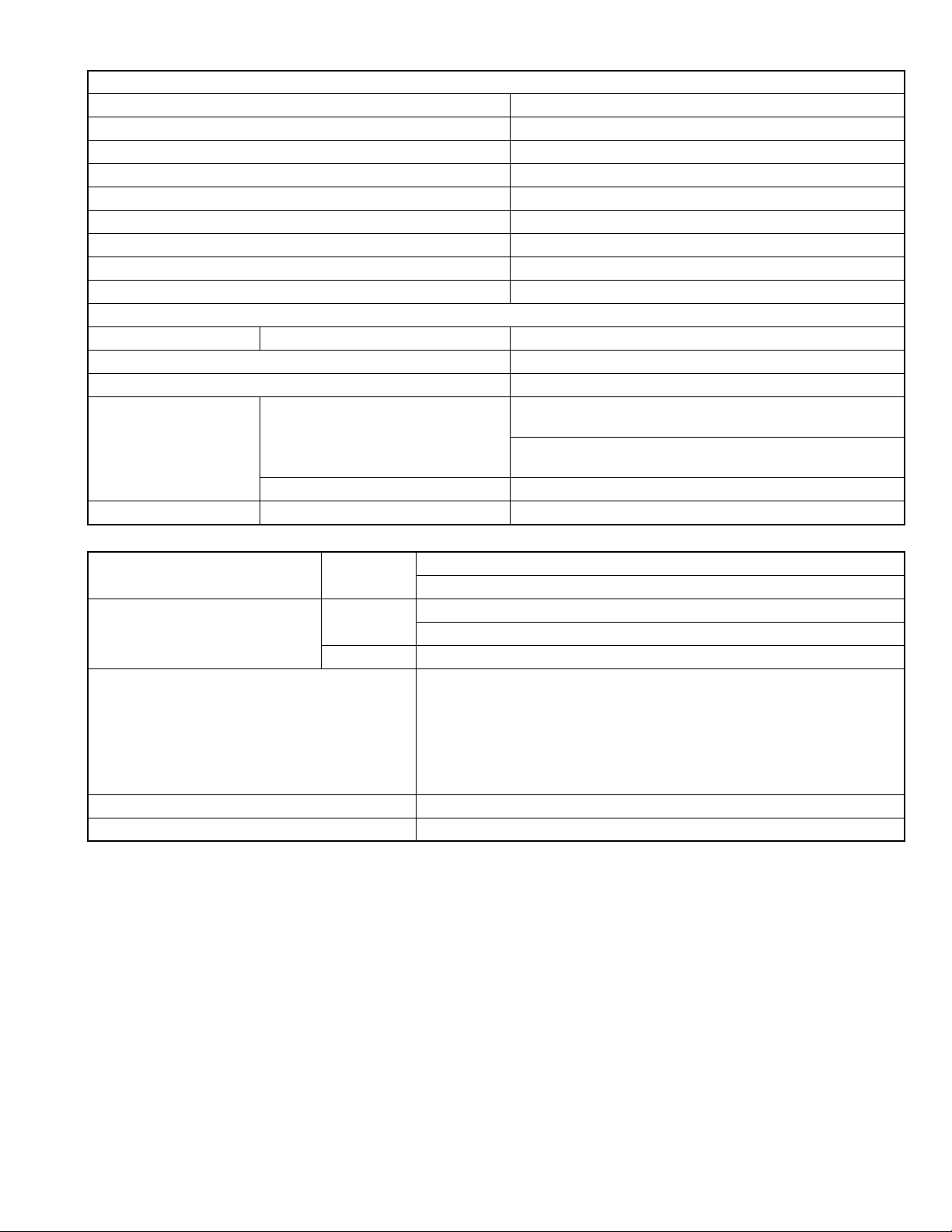
REMOVABLE MONITOR
Screen Size 7 inch wide liquid crystal display
Number of Pixel 336 960 pixels (480 vertical × 234 horizontal × 3)
Drive Method TFT (Thin Film Transistor) active matrix format
Color System NTSC
Aspect Ratio 16:9 (wide)
Allowable Storage Temperature -10°C to +60°C (14°F to 140°F)
Allowable Operating Temperature 0°C to +40°C (32°F to 104°F)
Dimensions (W × H × D) 170 mm × 141 mm × 15 mm (6-3/4 in. × 5-5/8 in. × 5/8 in.)
Mass 475 g (1.1 lbs)
GENERAL
Power Requirement Operating Voltage DC 14.4 V (11 V to 16 V allowance)
Grounding System Negative ground
Allowable Operating Temperature 0°C to +40°C (32°F to 104°F)
Dimensions (W × H × D) Installation Size 182 mm × 52 mm × 165 mm (7-3/16 in. × 2-1/16 in. × 6-1/2 in.)
(With sleeve-mounting plate Type B (standard))
182 mm × 52 mm × 160 mm (7-3/16 in. × 2-1/16 in. × 6-5/16 in.)
(With sleeve-mounting plate Type A)
Panel Size 188 mm × 58 mm × 14 mm (7-7/16 in. × 2-5/16 in. × 5/8 in.)
Mass 2.25 kg (5.1 lbs) (including monitor)
Hideaway unit
Input Terminals AV INPUT 1/2 Audio: 0.5 Vrms (Left/Right)
Video (composite): 1 Vp-p/75 Ω
Output Terminals (Level/Impedance) AV OUTPUT Audio: 2.0 V/20 kΩ load (full scale)
Video (composite): 1 Vp-p/75 Ω
PRE OUT Audio: 2.0 V/20 kΩ load (full scale)
Other Terminals System integration (TO MAIN UNIT)
FM/AM antenna (FM/AM ANTENNA)
AV bus (AV BUS)
CD changer (TO CHANGER)
Rear view camera/Center speaker (BACKCAMERA REMOTE/CENTER
SPEAKER)
Power cord (POWER)
Dimensions (W × H × D) 230 mm × 35 mm × 181 mm (9-1/16 in. × 1-7/16 in. × 7-3/16 in.)
Mass 1.3 kg (2.9 lbs)
Design and specifications are subject to change without notice.
(No.MA101)1-3
Page 4
1.1 Safety Precautions
SECTION 1
PRECAUTIONS
!
!
Burrs formed during molding may be left over on some parts of the chassis. Therefore,
pay attention to such burrs in the case of preforming repair of this system.
Please use enough caution not to see the beam directly or touch it in case of an
adjustment or operation check.
1-4 (No.MA101)
Page 5
1.2 Preventing static electricity
Electrostatic discharge (ESD), which occurs when static electricity stored in the body, fabric, etc. is discharged, can destroy the laser
diode in the traverse unit (optical pickup). Take care to prevent this when performing repairs.
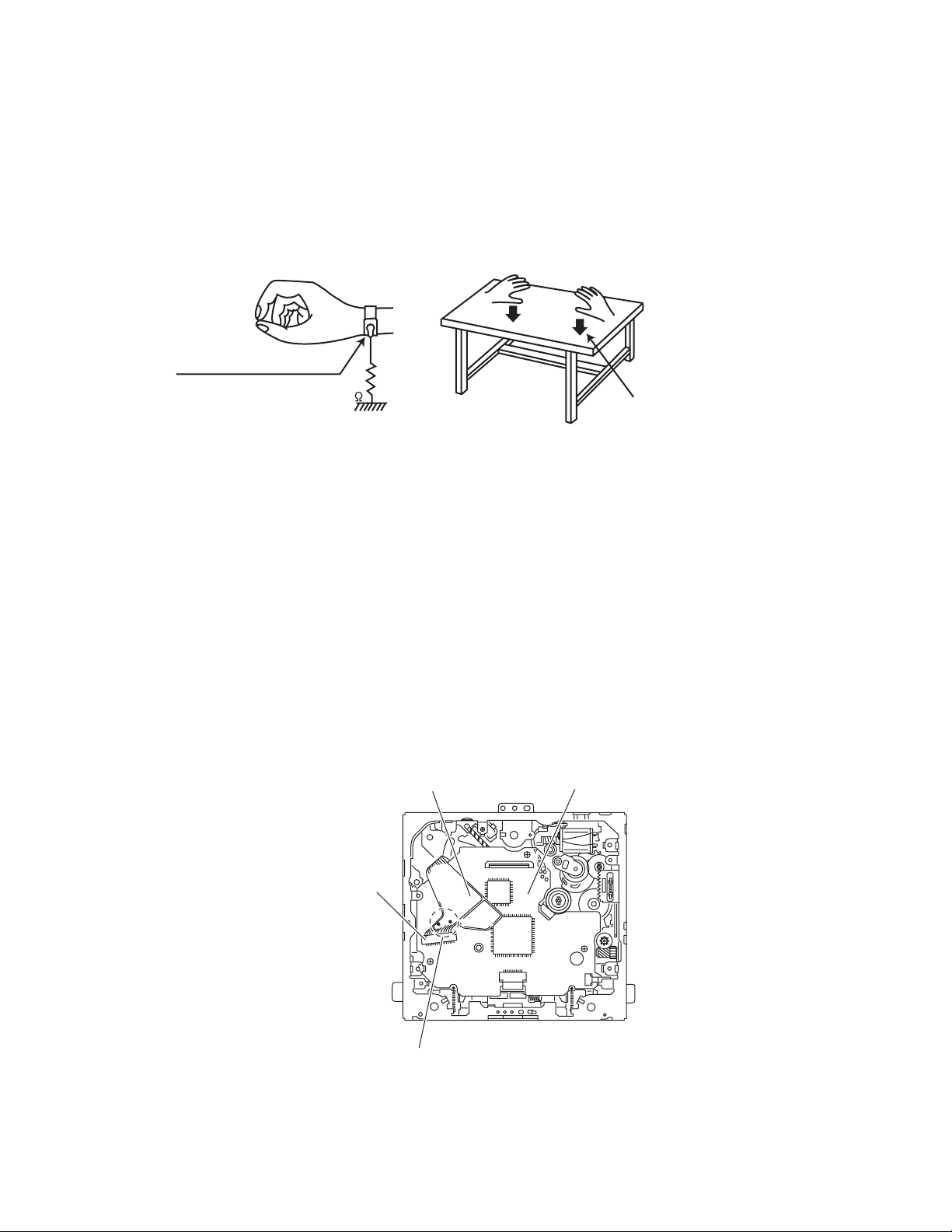
1.2.1 Grounding to prevent damage by static electricity
Static electricity in the work area can destroy the optical pickup (laser diode) in devices such as CD players.
Be careful to use proper grounding in the area where repairs are being performed.
(1) Ground the workbench
Ground the workbench by laying conductive material (such as a conductive sheet) or an iron plate over it before placing the
traverse unit (optical pickup) on it.
(2) Ground yourself
Use an anti-static wrist strap to release any static electricity built up in your body.
(caption)
Anti-static wrist strap
1M
Conductive material
(conductive sheet) or iron plate
(3) Handling the optical pickup
• In order to maintain quality during transport and before installation, both sides of the laser diode on the replacement optical
pickup are shorted. After replacement, return the shorted parts to their original condition.
(Refer to the text.)
• Do not use a tester to check the condition of the laser diode in the optical pickup. The tester's internal power source can easily
destroy the laser diode.
1.3 Handling the traverse unit (optical pickup)
(1) Do not subject the traverse unit (optical pickup) to strong shocks, as it is a sensitive, complex unit.
(2) Cut off the shorted part of the flexible cable using nippers, etc. after replacing the optical pickup. For specific details, refer to the
replacement procedure in the text. Remove the anti-static pin when replacing the traverse unit. Be careful not to take too long a
time when attaching it to the connector.
(3) Handle the flexible cable carefully as it may break when subjected to strong force.
(4) It is not possible to adjust the semi-fixed resistor that adjusts the laser power. Do not turn it.
1.4 Attention when traverse unit is decomposed
*Please refer to "Disassembly method" in the text for the CD pickup unit.
• Apply solder to the short land before the flexible wire is disconnected from the connector on the CD pickup unit.
(If the flexible wire is disconnected without applying solder, the CD pickup may be destroyed by static electricity.)
• In the assembly, be sure to remove solder from the short land after connecting the flexible wire.
Flexible wire
Front end board
CN101
Short-circuit points
(No.MA101)1-5
Page 6
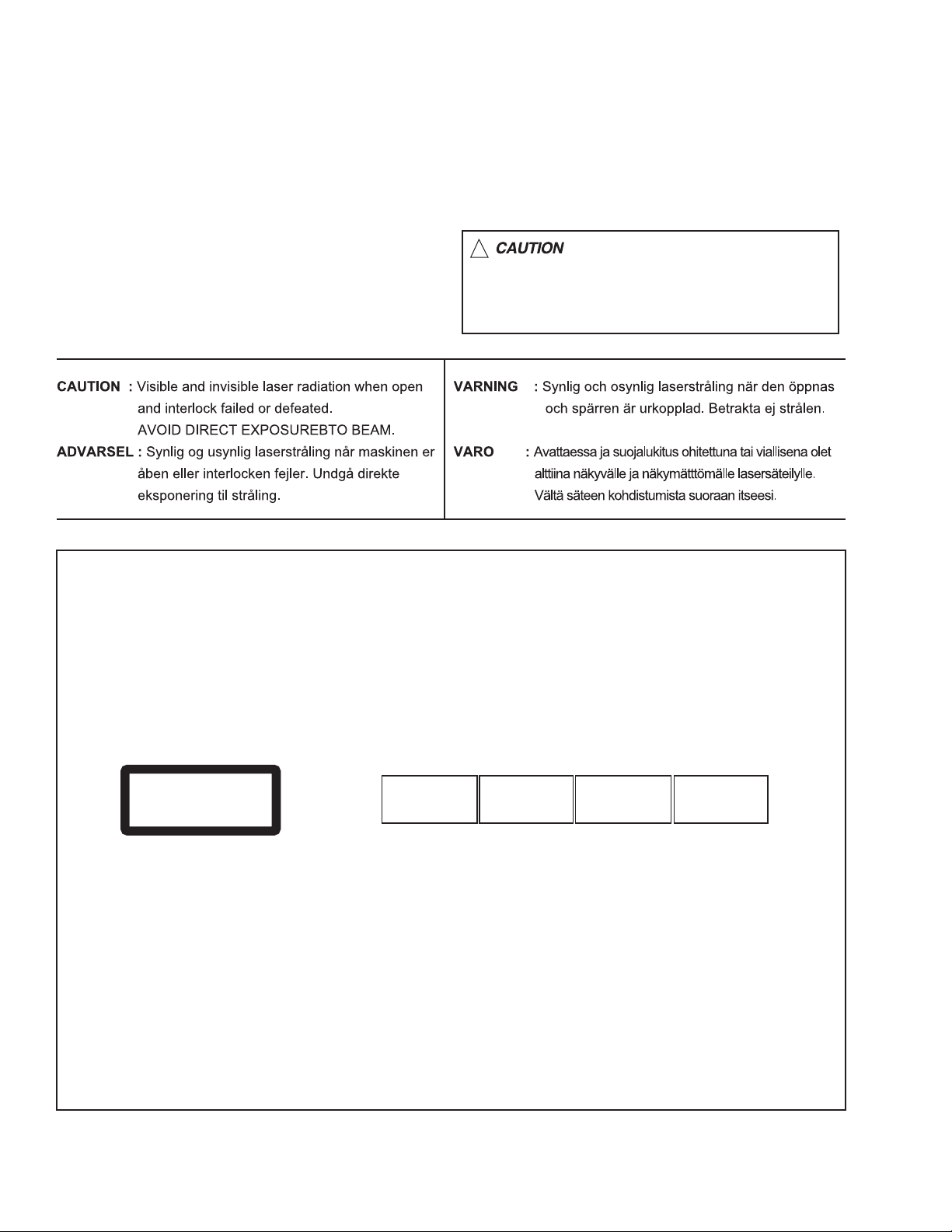
1.5 Important for laser products
!
1.CLASS 1 LASER PRODUCT
2.DANGER : Invisible laser radiation when open and inter
lock failed or defeated. Avoid direct exposure to beam.
3.CAUTION : There are no serviceable parts inside the
Laser Unit. Do not disassemble the Laser Unit. Replace
the complete Laser Unit if it malfunctions.
4.CAUTION : The CD,MD and DVD player uses invisible
laser radiation and is equipped with safety switches which
prevent emission of radiation when the drawer is open and
the safety interlocks have failed or are defeated. It is
dangerous to defeat the safety switches.
5.CAUTION : If safety switches malfunction, the laser is able
to function.
6.CAUTION : Use of controls, adjustments or performance of
procedures other than those specified here in may result in
hazardous radiation exposure.
Please use enough caution not to
see the beam directly or touch it
in case of an adjustment or operation
check.
REPRODUCTION AND POSITION OF LABELS
WARNING LABEL
CAUTION : Visible and Invisible
CLASS 1
LASER PRODUCT
laser radiation when open and
interlock failed or defeated.
AVOID DIRECT EXPOSURE TO
BEAM. (e)
ADVARSEL : Synlig og usynlig
laserstråling når maskinen er
åben eller interlocken fejeler.
Undgå direkte eksponering til
stråling. (d)
VARNING : Synlig och
osynling laserstrålning när
den öppnas och spärren är
urkopplad. Betrakta ej
strålen. (s)
VARO : Avattaessa ja suojalukitus
ohitettuna tai viallisena olet alttiina
näkyvälle ja näkymättömälle
lasersäteilylle. Vältä säteen
kohdistumista suoraan itseesi. (f)
1-6 (No.MA101)
Page 7

SECTION 2
SPECIFIC SERVICE INSTRUCTIONS
This service manual does not describe SPECIFIC SERVICE INSTRUCTIONS.
(No.MA101)1-7
Page 8
SECTION 3
DISASSEMBLY
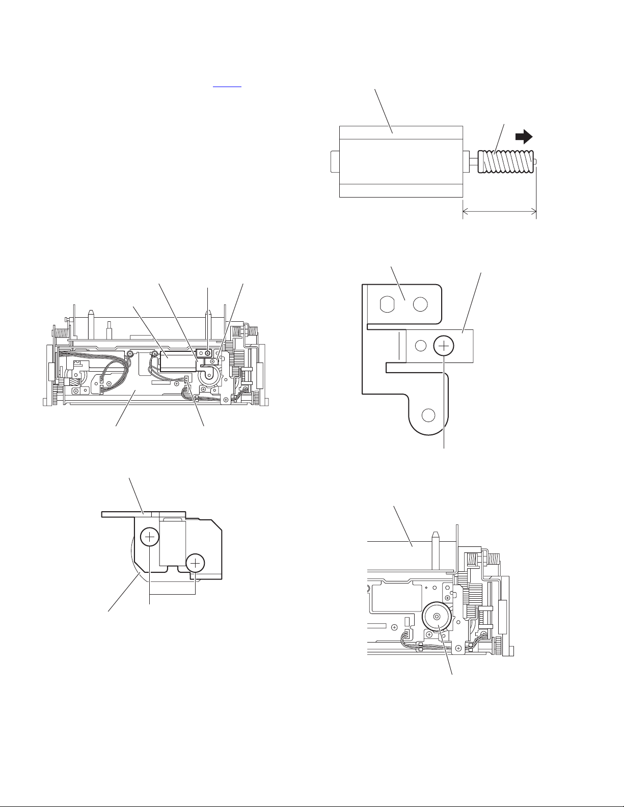
3.1 Receiver unit section
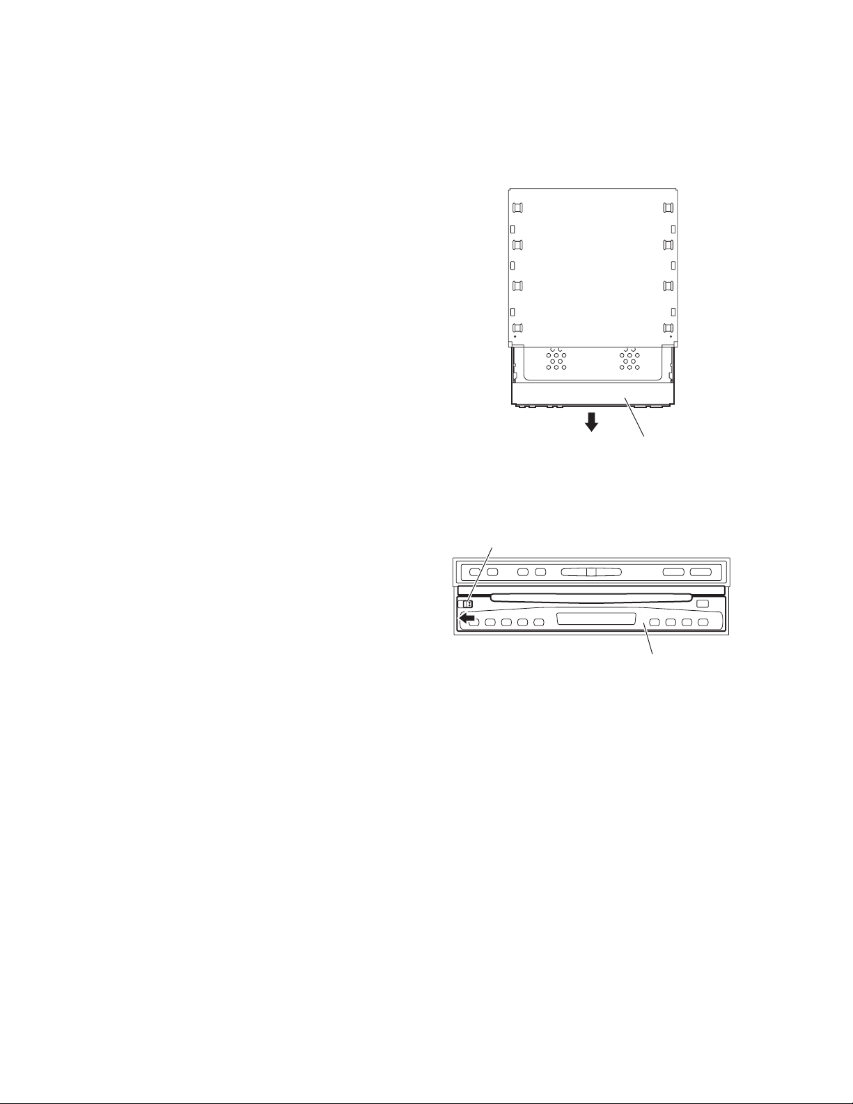
3.1.1 Removing the display unit
(See Fig.1)
From the top side of the main body, pull the display unit out of the
main body in the direction of the arrow.
3.1.2 Removing the detach panel assembly
(See Fig.2)
From the front side of the main body, slide the detach button in
the direction of the arrow and remove the detach panel assembly.
Display unit
Fig.1
Detach button
Detach panel assembly
Fig.2
1-8 (No.MA101)
Page 9
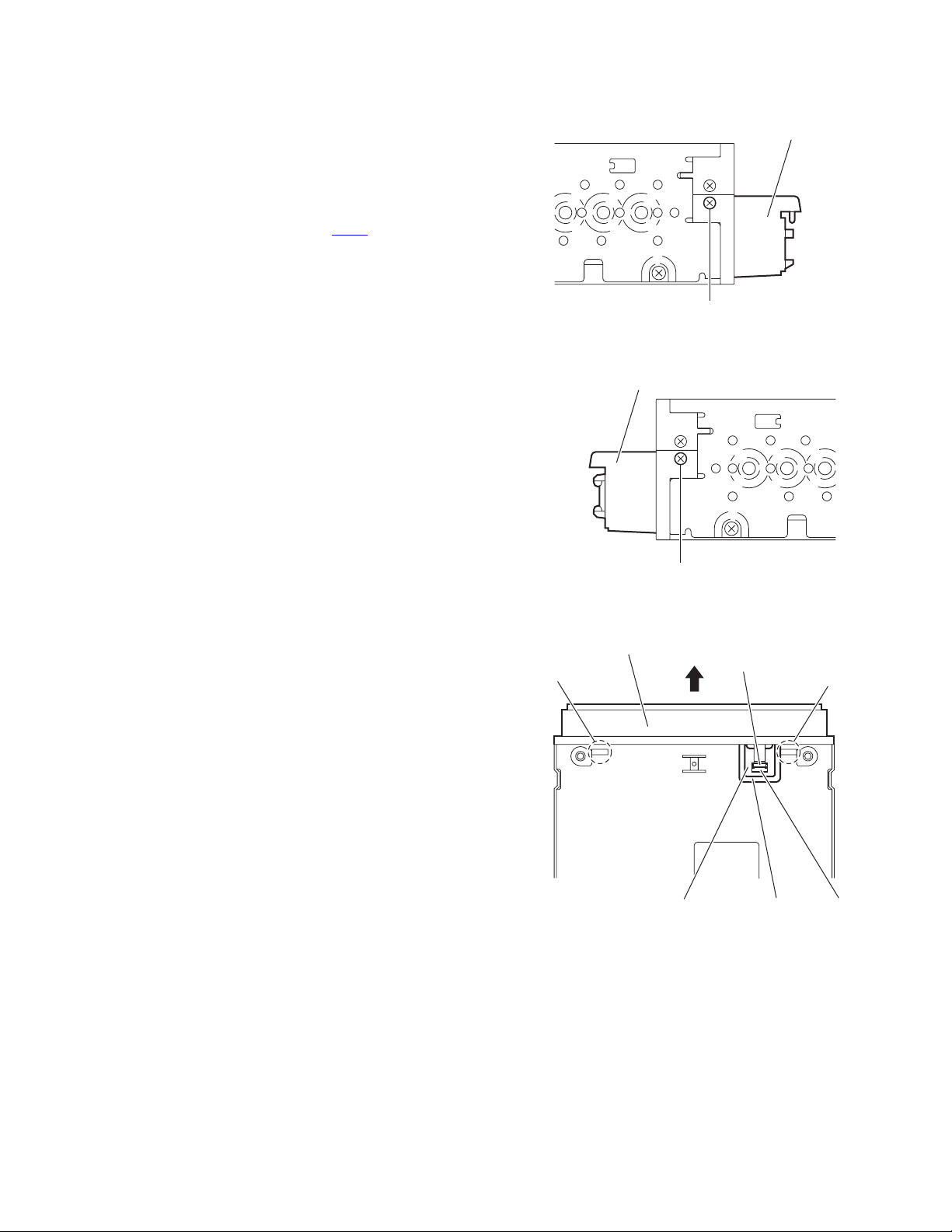
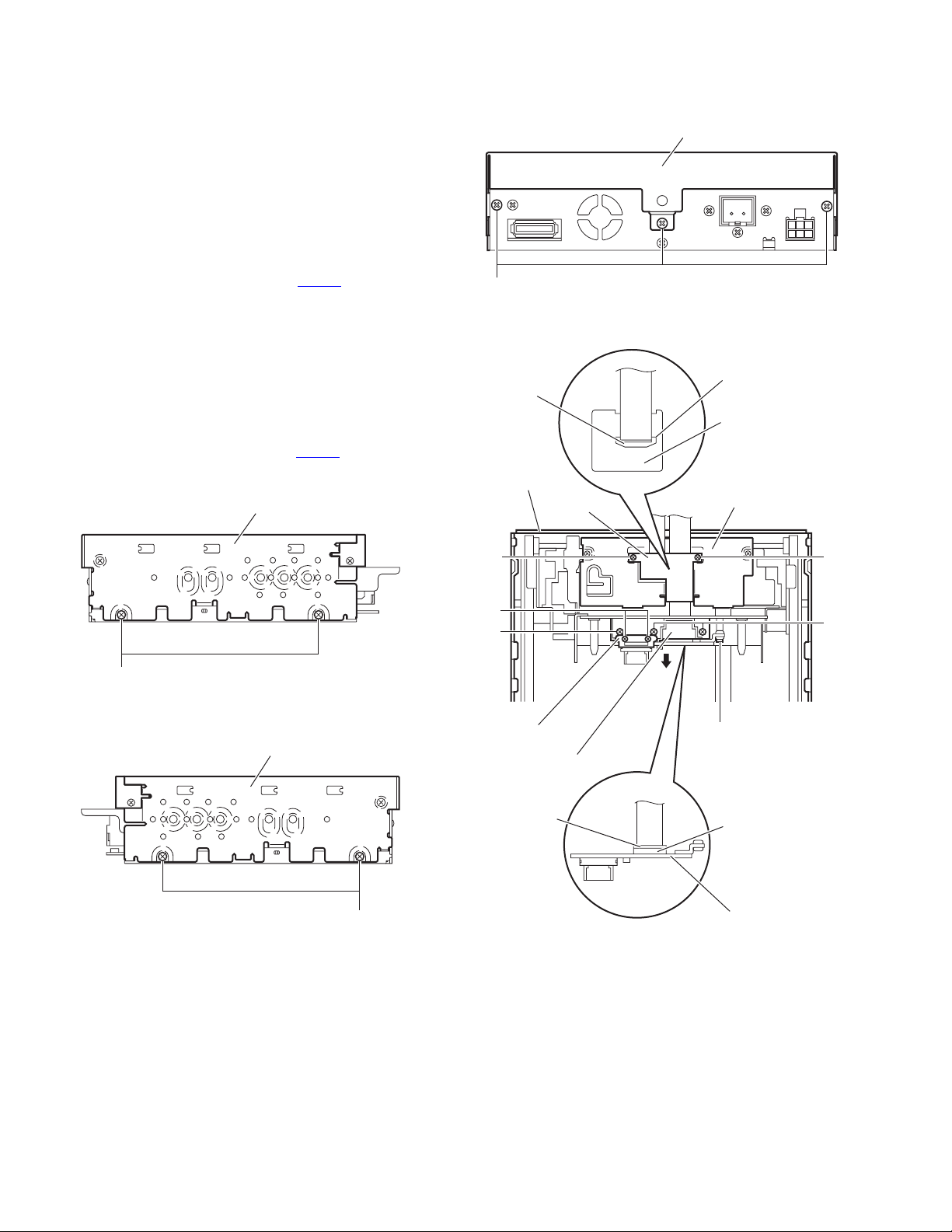
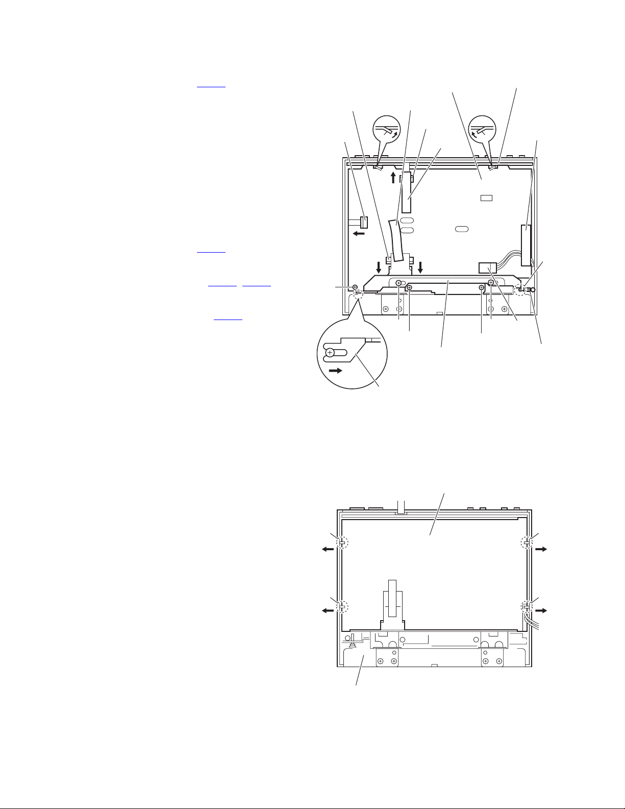
3.1.3 Removing the front panel assembly
(See Figs.3 to 5)
• Remove the display unit and detach panel assembly as re-
quired.
(1) From the both sides of the main body, remove the two
screw A attaching the front panel assembly. (See Figs.3
and 4)
(2) From the bottom side of the main body, remove the FPC
cover. (See Fig.5.)
(3) Release the lock of the connector CN75
and disconnect the card wire. (See Fig.5.)
(4) Release the joints a and remove the front panel assembly
from the main body in the direction of the arrow. (See
Fig.5.)
on the main board
Front panel assembly
A
Fig.3
Front panel assembly
Front panel assembly
a
Main board
A
Fig.4
Fig.5
Lock
FPC cover
a
CN75
(No.MA101)1-9
Page 10
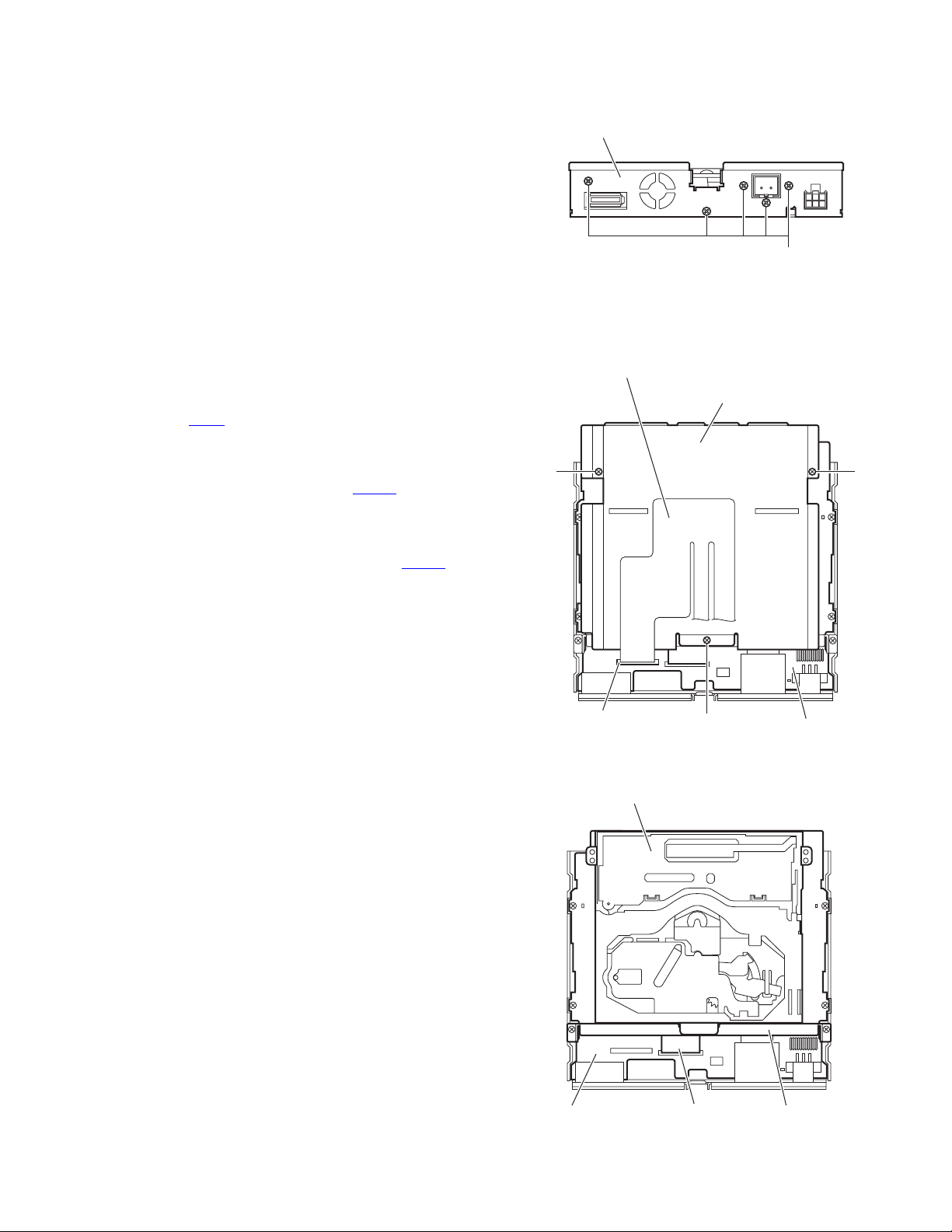
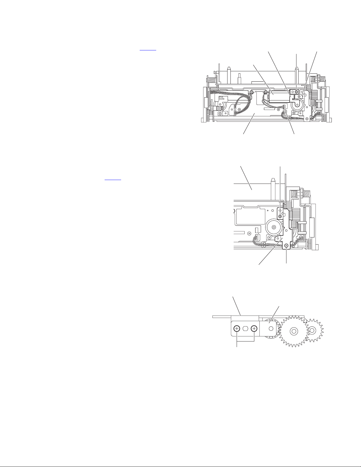
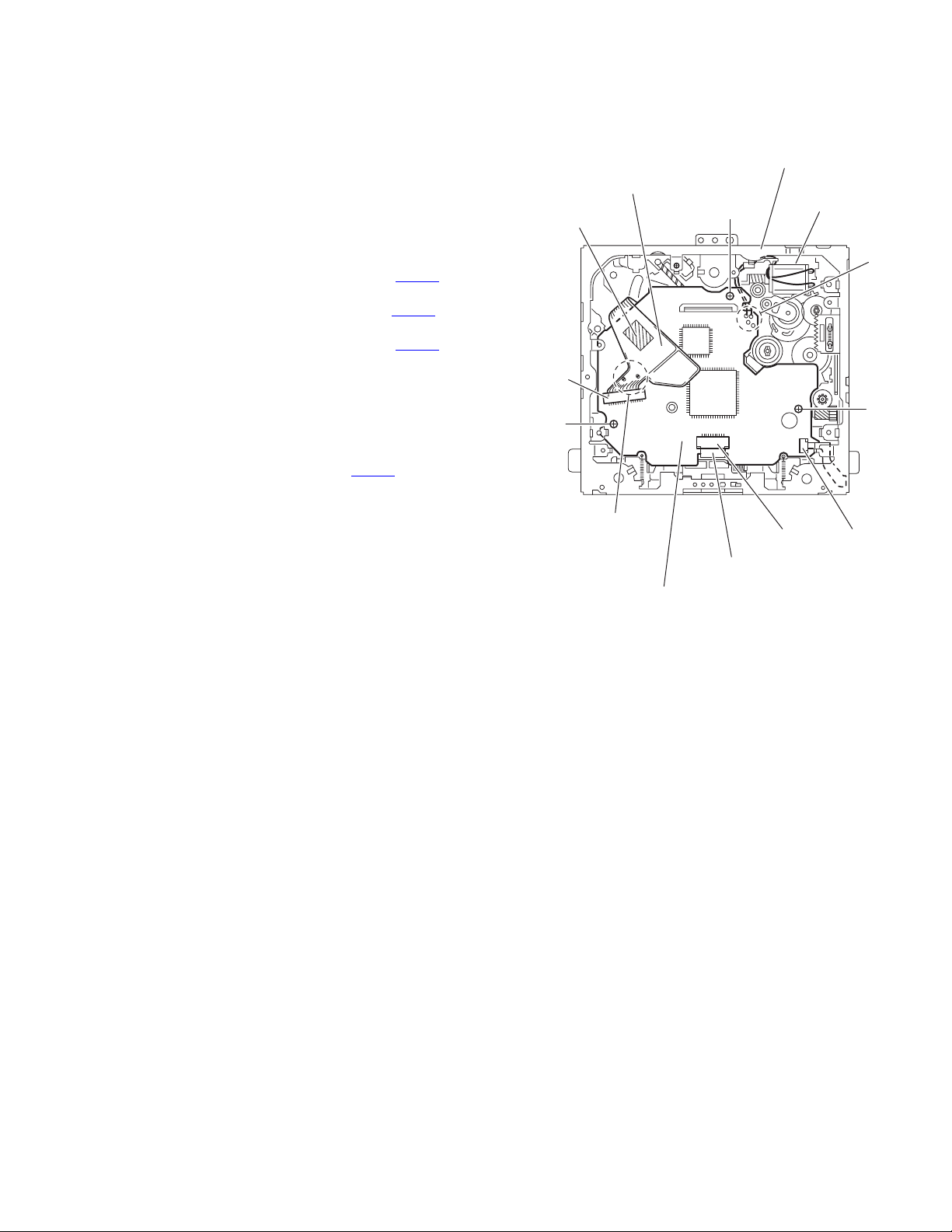
3.1.4 Removing the top drive unit
(See Figs.6 to 9)
• Prior to performing the following procedures, remove the dis-
play unit, detach panel assembly and front panel assembly.
(1) From the both sides of the main body, remove the four
screws B attaching the top drive unit. (See Figs.6 and 7.)
(2) From the rear side of the main body, remove the three
screws C attaching the top drive unit. (See Fig.8.)
(3) Remove the top drive unit from the main body and turn it
inside out. (See Fig.9.)
(4) Remove the two screws C attaching the F.P.C. guide on
the display drive unit. (See Fig.9.)
(5) Release the lock of the connector CN301
nism board and disconnect the flexible wire. (See Fig.9.)
(6) Remove the two screws D attaching the CN guide. (See
Fig.9.)
(7) Remove the three screws E attaching the PWB base. (See
Fig.9.)
(8) Remove the screw F attaching the connect board. (See
Fig.9.)
(9) Take out the connect board in the direction of the arrow.
(See Fig.9.)
(10) Release the lock of the connector CN391
board and disconnect the flexible wire. (See Fig.9.)
Top drive unit
on the mecha-
on the connect
B
Lock
Top drive unit
F.P.C.guide
Top drive unit
Fig.8
CN301
Motor board
Display drive unit
B
Fig.6
Top drive unit
Fig.7
B
C
D
E
CN guide
PWB base
Lock
C
E
F
CN391
Connect board
Fig.9
1-10 (No.MA101)
Page 11
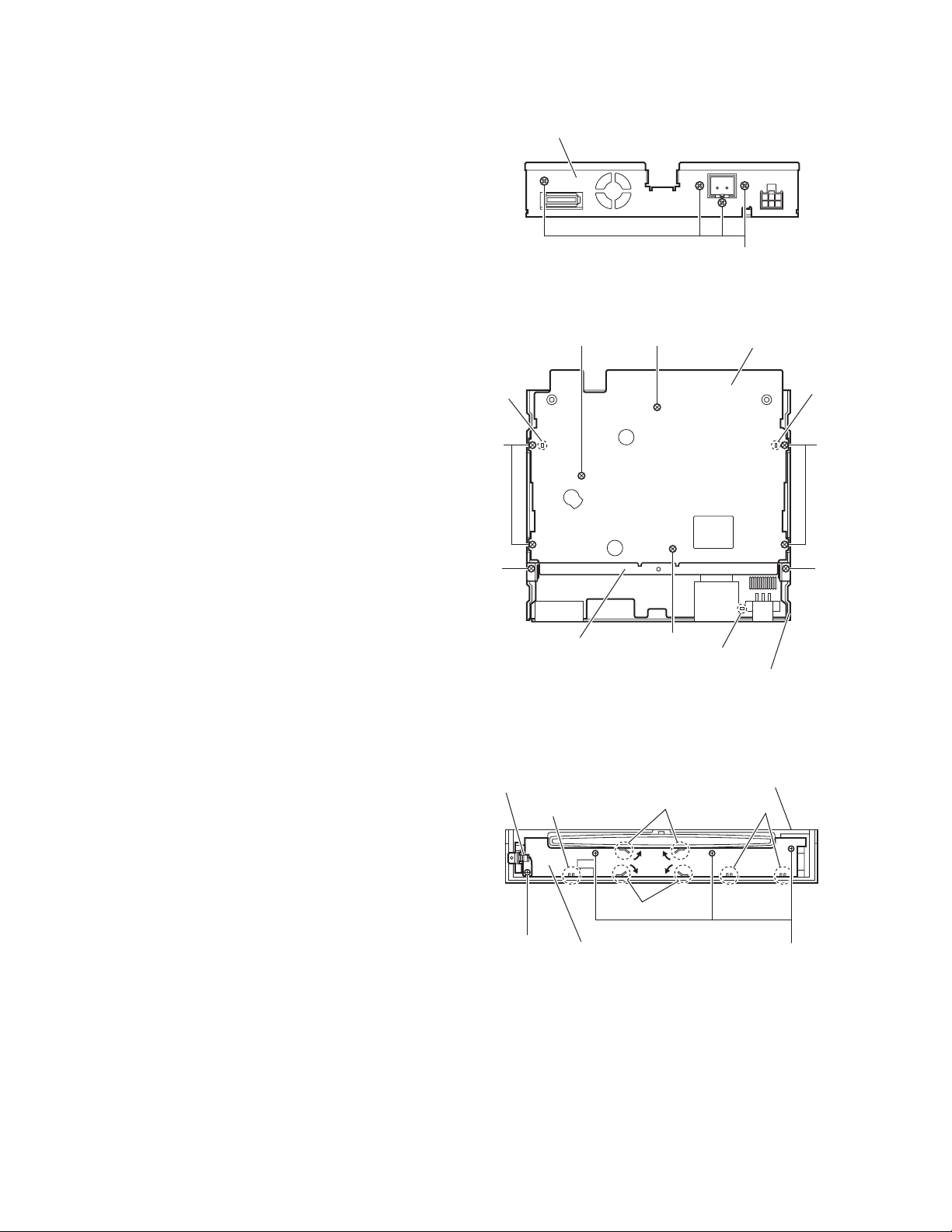
3.1.5 Removing the rear bracket
(See Figs.10)
• Prior to performing the following procedures, remove the dis-
play unit, detach panel assembly, front panel assembly and top
drive unit.
From the rear side of the main body, remove the five screws G
attaching the rear bracket.
3.1.6 Removing the DVD mechanism assembly
(See Figs.11 and 12)
• Prior to performing the following procedures, remove the dis-
play unit, detach panel assembly, front panel assembly and top
drive unit.
(1) From the top side of the main body, release the lock of the
connector CN52
and disconnect the flexible wire. (See Fig.11.)
(2) Remove the two screws H and screw J attaching the mech-
anism cover. (See Fig.11.)
(3) Release the lock of the connector CN101
board in an upward direction and disconnect the card wire.
(See Fig.12.)
Reference:
When connecting the card wire to the connector CN101
it through the lower part of the mechanism bracket. (See
Fig.12.)
on the main board in an upward direction
on the main
, pass
Rear bracket
G
Fig.10
Flexible wire
Mechanism cover
HH
CN52
DVD mechanism assembly
Main board
J
Fig.11
CN101
Fig.12
Main board
Mechanism bracket
(No.MA101)1-11
Page 12
3.1.7 Removing the main board
(See Figs.13 and 14)
• Prior to performing the following procedures, remove the dis-
play unit, detach panel assembly, front panel assembly, top
drive unit and DVD mechanism assembly.
(1) From the rear side of the main body, remove the four
screws K attaching the rear bracket. (See Fig.13.)
(2) From the top side of the main body, remove the two screws
L attaching the mechanism bracket on the bottom chassis
assembly. (See Fig.14.)
(3) Remove the five screws M and two screws N attaching the
main board. (See Fig.14.)
(4) Take out the main board from the bottom chassis assem-
bly.
Reference:
When attaching the main board on the bottom chassis assembly, align the projections b of the bottom chassis assembly in
the hole of the main board. (See Fig.14.)
Rear bracket
b
Fig.13
MN
K
Main board
b
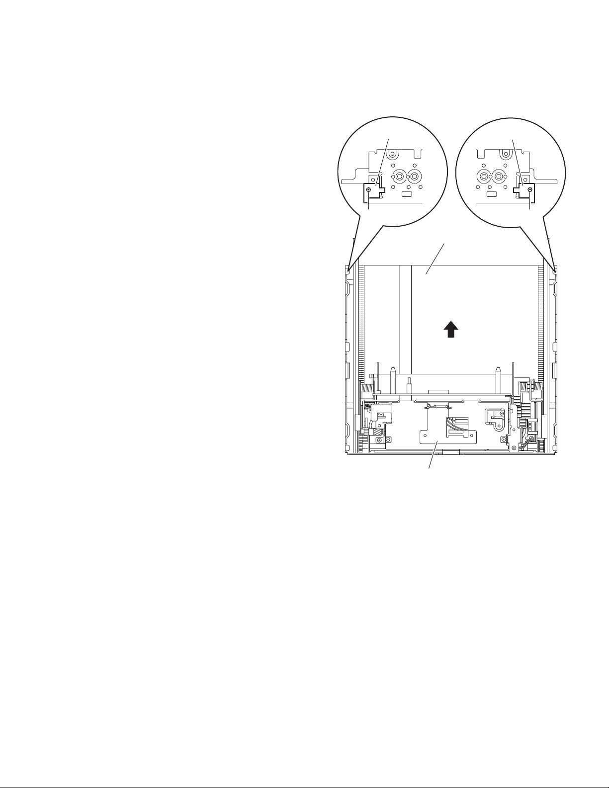
3.1.8 Removing the front board
(See Fig.15)
• Prior to performing the following procedures, remove the de-
tach panel assembly and front panel assembly.
(1) From the inside of the front panel assembly, remove the
three screws P and screw P' attaching the front board.
(2) Take out the lock lever assembly from the front panel as-
sembly.
(3) Bend the hooks c in the direction of the arrow.
(4) Release the front board from the sections d and take out
the front board from the front panel assembly.
Reference:
When attaching the screw P', attach the lock lever assembly
with it.
M
L
Mechanism bracket
Lock lever assembly
d
Front board
P'
N
Fig.14
c
c
b
Bottom chassis assembly
Front panel assembly
M
L
d
P
1-12 (No.MA101)
Fig.15
Page 13
3.2 Top drive unit section
• Remove the top drive unit from the main body.
(See "3.1.4 Removing the top drive unit".)
3.2.1 Removing the display drive unit
(See Fig.1)
(1) From the both sides of the top drive unit, remove the two
screws A attaching the display guides L/R and remove the
display guides L/R from the top chassis assembly.
(2) Slide the display drive unit by manual operation in the di-
rection of the arrow and remove it from the top chassis assembly.
Display guide L
Display guide R
A
Display drive unit
A
Top chassis assembly
Fig.1
(No.MA101)1-13
Page 14
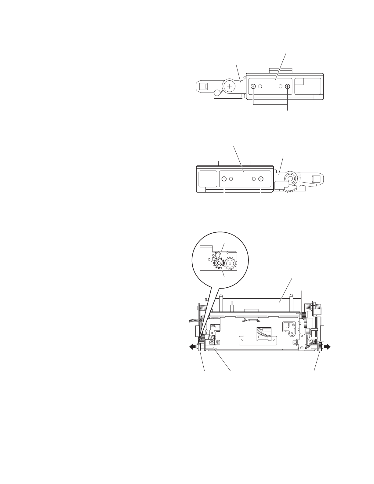
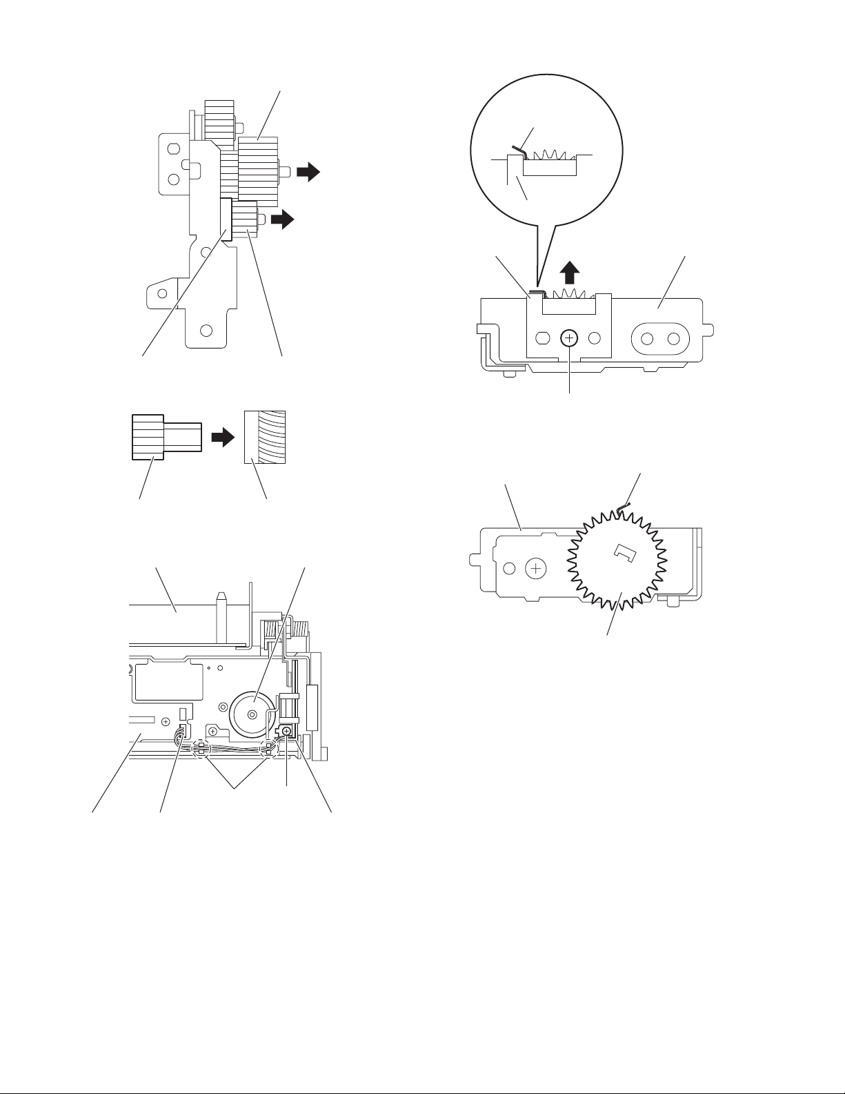
3.2.2 Removing the drive gears and forth gear
(See Figs.2 to 4)
• Remove the display drive unit.
(1) From the both sides of the display drive unit, remove the
four screws B attaching the guide rails (L)/(R). (See Figs.2
and 3.)
(2) From the top side of the display drive unit, pull the drive
gears out of a drive gear shaft in the direction of the arrow
while holding the drive gear shaft. (See Fig.4.)
Reference:
Remove the drive gear shaft as required. (See Fig.4.)
(3) From the left side of the display drive unit, remove the
E.ring fixing the forth gear. (See Fig.4.)
(4) Remove the forth gear toward this side. (See Fig.4.)
Guide rail (L)
Display drive unit
B
Fig.2
Guide rail (R)
Display drive unit
B
Fig.3
E.ring
Forth gear
Drive gear Drive gearDrive gear shaft
Fig.4
Display drive unit
1-14 (No.MA101)
Page 15
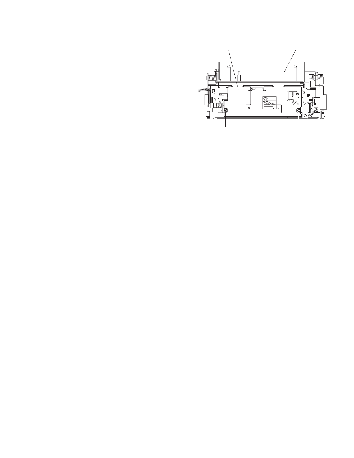
3.2.3 Removing the cover
(See Fig.5)
• Remove the display drive unit.
From the top side of the display drive unit, remove the two
screws C attaching the cover.
Display drive unitCover
C
Fig.5
(No.MA101)1-15
Page 16
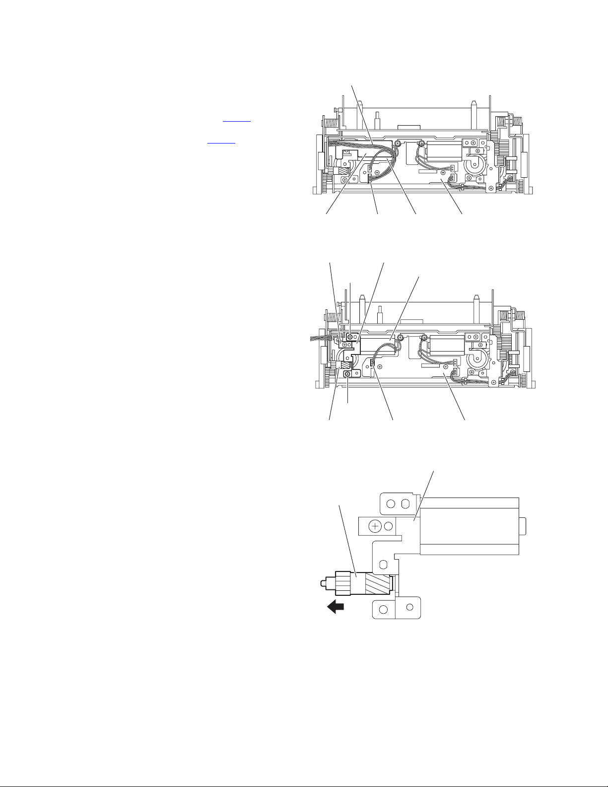
3.2.4 Removing the third gear, worm gear and double worm
(See Figs.6 to 11)
• Remove the display drive unit and cover.
(1) Remove the wire sheet with the wire from the motor. (See
Fig.6.)
Reference:
Disconnect the wire from the connector CN332
motor board as required.
(2) Disconnect the wire from the connector CN312
tor board. (See Fig.7.)
(3) Remove the two screws D attaching the motor bracket (S).
(See Fig.7.)
(4) Take out the motor bracket (S), worm guide, motor and
third gear together. (See Fig.7.)
(5) Pull the third gear out of the motor bracket (S) in the direc-
tion of the arrow. (See Fig.8.)
(6) Remove the two screws E attaching the motor and remove
the motor from the motor bracket (S). (See Fig.9.)
(7) Pull the worm gear out of the motor. (See Fig.10.)
Reference:
When inserting the warm gear in the shaft of the motor,
insert it by a measurement of a rule. (See Fig.10.)
(8) From the top side of the display drive unit, pull the double
worm in an upward direction. (See Fig.11.)
on the
on the mo-
Wire
Wire sheet Motor boardCN332 Motor
Fig.6
Worm guide Motor bracket (S)
D
Motor
D
Third gear Motor boardCN312
Third gear
Fig.7
Motor bracket (S)
Fig.8
1-16 (No.MA101)
Page 17
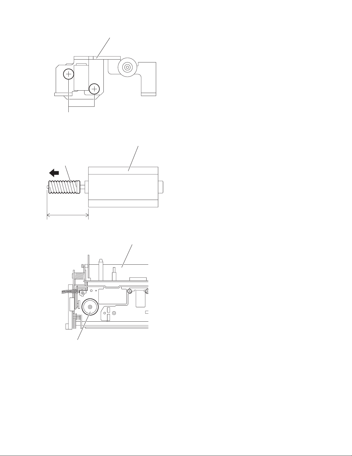
E
Worm gear
Motor bracket (S)
Fig.9
Motor
16 ± 0.1 (mm)
Double worm
Fig.10
Display drive unit
Fig.11
(No.MA101)1-17
Page 18
3.2.5 Removing the worm gear, motor bracket (A) and third worm
(See Figs.12 to 16)
• Remove the display drive unit and cover.
(1) Disconnect the wire from the connector CN311 on the mo-
tor board. (See Fig.12.)
(2) Remove the screw F attaching the motor bracket (A). (See
Fig.12.)
(3) Take out the motor bracket (A), worm guide and motor to-
gether. (See Fig.12.)
(4) Remove the two screws G attaching the motor and remove
the motor from the motor bracket (A). (See Fig.13.)
(5) Pull the worm gear out of the motor. (See Fig.14.)
Reference:
When inserting the warm gear in the shaft of the motor,
insert it by a measurement of a rule. (See Fig.14.)
(6) Remove the screw H attaching the worm guide to the motor
bracket (A). (See Fig.15.)
(7) From the top side of the display drive unit, pull the third
worm in an upward direction. (See Fig.16.)
Worm guideMotor bracket (A)
F
Motor
Motor
Fig.14
Motor bracket (A)
Worm gear
16 ± 0.1 (mm)
Worm guide
Motor board CN311
Fig.12
Motor bracket (A)
Motor
G
Fig.13
H
Fig.15
Display drive unit
Third worm
Fig.16
1-18 (No.MA101)
Page 19
3.2.6 Removing the second wheel and R.L.S. gear
(See Figs.17 to 24)
• Remove the display drive unit and cover.
(1) Disconnect the wire from the connector CN311
tor board. (See Fig.17.)
(2) Remove the screw J attaching the motor bracket (A). (See
Fig.17.)
(3) Take out the motor bracket (A), worm guide and motor to-
gether. (See Fig.17.)
(4) Remove the two screws K attaching the gear bracket as-
sembly. (See Fig.18.)
(5) Take out the gear bracket assembly with other parts from
the display drive unit.
(6) From the left side of the gear bracket assembly, remove the
two screws L attaching the gear bracket cover. (See
Fig.19.)
(7) Pull out the joint gear in the direction of the arrow. (See
Fig.20.)
(8) Pull out the hex gear and second wheel together in the di-
rection of the arrow. (See Fig.20.)
(9) Pull the second wheel out of the hex gear. (See Fig.21.)
(10) Pull the third gear in an upward direction. (See Fig.22.)
(11) From the top side of the display drive unit, disconnect the
wire from the connector CN331
Fig 22.)
(12) Remove the screw M attaching the R.L.S. bracket. (See
Fig.22.)
(13) Take out the R.L.S. barcket with other parts from the dis-
play drive unit. (See Fig.22.)
Reference:
When attaching the R.L.S. bracket, pass the wire
through the sections a on the wire holder as before. (See
Fig.22.)
(14) From the back side of the R.L.S. bracket, remove the screw
N attaching the R.L.S. spring to the R.L.S. barcket and remove the R.L.S. spring in the direction of the arrow. (See
Fig.23.)
Reference:
When attaching the R.L.S. spring, hang the torsion
spring (R.L.S.) on the R.L.S. spring as before. (See
Fig.23.)
(15) From the front side of the R.L.S. bracket, remove the
R.L.S. gear toward this side. (See Fig.24.)
Reference:
When attaching the R.L.S. gear, attach the torsion spring
(R.L.S.) with it as before. (See Fig.24.)
on the motor board. (See
on the mo-
Motor
Motor board CN311
Fig.17
Display drive unit K
Gear bracket assembly
Fig.18
Gear bracket assembly
Gear bracket cover
K
Worm guideMotor bracket (A)
J
L
Fig.19
(No.MA101)1-19
Page 20
Joint gear
Torsion spring (R.L.S.)
R.L.S. spring
Hex gearSecond wheel
Fig.20
Hex gear Second wheel
Fig.21
Display drive unit Third gear
R.L.S. spring
R.L.S. bracket
R.L.S. bracket
N
Fig.23
Torsion spring (R.L.S.)
R.L.S. gear
a
Motor board CN331 R.L.S. bracket
Fig.22
1-20 (No.MA101)
M
Fig.24
Page 21
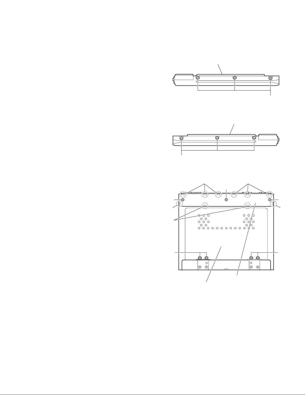
3.3 Display unit section
• Remove the display unit from the main body.
(See "3.1.1 Removing the display unit".)
3.3.1 Removing the display back panel
(See Figs.1 to 3)
(1) From the both sides of the display unit, remove the six
screws A attaching the display back panel. (See Figs.1 and
2.)
(2) From the rear side of the display unit, remove the three
screws A attaching the display rear cover. (See Fig.3.)
(3) Release the joints a first and relese the joint b. (See Fig.3.)
(4) Remove the display rear cover.
Note:
When releasing the joints a and joints b, take care not to
break the claws of the display rear cover. (See Fig.3.)
(5) Remove the four screws B attaching the display back pan-
el. (See Fig.3.)
(6) Take out the display back panel from the display unit.
Display back panel
A
Fig.1
Display back panel
A
Fig.2
a
a
A
A
a
b
A
a
BB
Display rear cover
Display back panel
Fig.3
(No.MA101)1-21
Page 22
3.3.2 Removing the switch board
(See Fig.4)
• Removing the switch board (See Fig.4)
(1) Release the lock of the connector CN402 on the display
board in the direction of the arrow and disconnect the card
wire.
Reference:
After connecting the card wire, fix it with the spacer(H) as
before.
(2) Take out the switch board from the display unit.
3.3.3 Removing the display board
(See Fig.4)
• Prior to performing the following procedures, remove the dis-
play back panel.
Reference:
Remove the switch board as required.
(1) Release the lock of the connector CN402
board in the direction of the arrow and disconnect the card
wire.
(2) Release the locks of the connectors (CN421
the display board in the direction of the arrow and disconnect the flexible wire.
(3) Disconnect the wire from the connector CN471
play board.
(4) Bend the hooks c in the direction of the arrow.
(5) Remove the two screws C attaching the slider assembly.
(6) Remove the tension spring from the section d and remove
the slider assembly in the direction of the arrow 1.
(7) Remove the three screws D attaching the display board
and take out the display board from the display unit.
Reference:
After connecting the each wire, fix them with the spacer(H) as
before.
on the display
, CN451) on
on the dis-
CN451
CN421
D
c
1
Slider assembly
Display board
Spacer(H)
CN402
Spacer(H)
C
D
Slider assembly
Fig.4
Switch board
Spacer(H)
c
CN471
C
D
Tension spring
d
3.3.4 Removing the LCD module
(See Fig.5)
• Prior to performing the following procedures, remove the dis-
play back panel and display board.
Release the claws e in the direction of the arrow and take out
the LCD module from the display panel.
e
e
Display panel
LCD module
e
e
Fig.5
1-22 (No.MA101)
Page 23
3.4 DVD mechanism assembly section
3.4.1 Removing the front end board
(See Fig.1)
Caution:
Before disconnecting the flexible wire extending from the DVD
pickup, solder the short-circuit point on the flexible wire using
a grounding soldering iron.
If you do not follow this instruction, the DVD pickup may be
damaged.
(1) Turn over the body, and solder the short-circuit points on
the flexible wire extending from the DVD pickup.
(2) Disconnect the flexible wire from connector CN101
front end board.
(3) Disconnect the card wire from connector CN201
front end board.
(4) Disconnect the flexible wire from connector CN202
front end board.
(5) Unsolder two soldered points a on the front end board and
remove the wire extending from the feed motor.
(6) Remove the two screws A and screw B attaching the front
end board.
Caution:
• As the flexible wire to be connected to CN101
attach it to the front end board using a double tape.
• After reassembling, unsolder the short-circuit points.
on the
on the
on the
, make sure to
Flexible wire
Double tape
CN101
A
Short-circuit points
DVD mechanism assembly
A
Card wire
Feed motor
CN201
CN202
a
B
Front end board
Fig.1
(No.MA101)1-23
Page 24
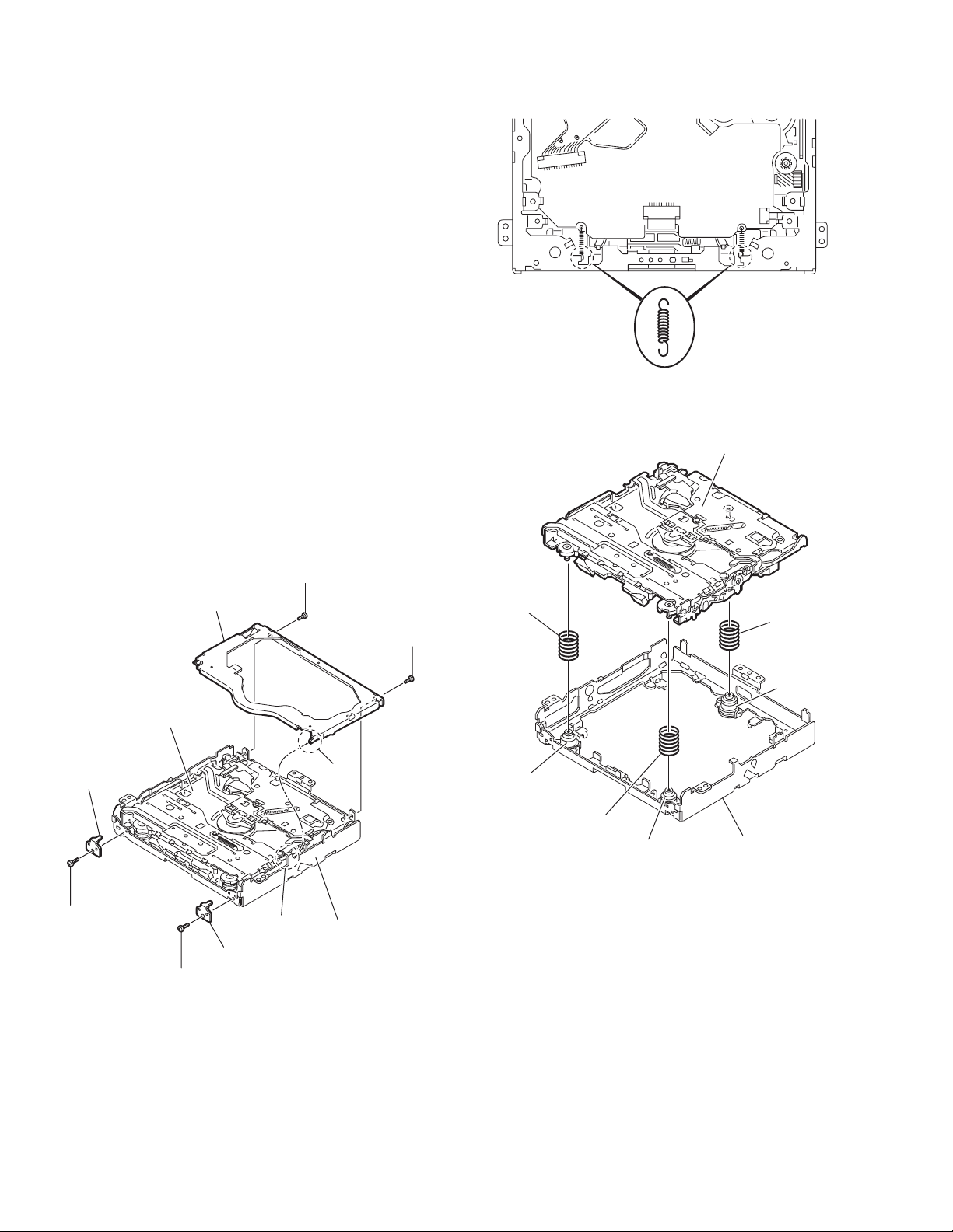
3.4.2 Removing the top cover
(See Fig.2)
(1) Remove the two screws C attaching the top cover on the
back of the body.
(2) Remove the top cover upward.
Reference:
When reassembling, set part b of the top cover under the
bending part c of the chassis frame.
3.4.3 Removing the mechanism section
(See Figs.2 to 4)
• Remove the top cover.
(1) Remove the two screws D attaching the right and left stop-
pers on the front side. (See Fig.2.)
(2) Remove the two floating springs on the bottom of the body.
(See Fig.3.)
(3) Move the mechanism section upward and remove from the
chassis frame.
(4) The three damper springs (damper SP. (F) and damper
SP. (R)) come off from the dampers (damper(F) and damper (R)). (See Fig.4.)
Caution:
• When reassembling, reattach the damper spring to the
damper respectively and insert the three shafts on the bottom of the mechanism to the dampers.
• Before inserting the shaft to the dampers, apply IPA to the
hole of the dampers.
Floating spring
Fig.3
Mechanism section
Top cover
DVD mechanism assembly
Stopper
D
Stopper
D
Fig.2
C
c
Chassis frame
Damper SP. (F)
(Silver)
C
b
Damper (F)
(Black)
Damper SP. (F)
(Silver)
Damper (F)
(Black)
Fig.4
Damper SP. (R)
(Red)
Damper (R)
(Purple)
Chassis frame
1-24 (No.MA101)
Page 25
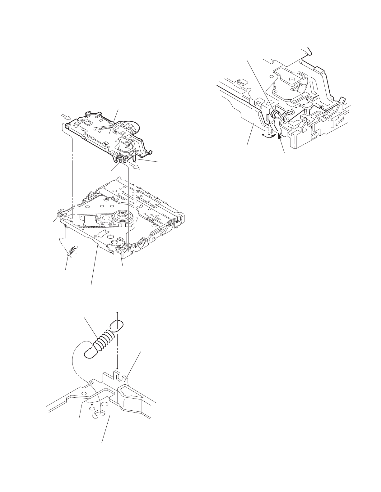
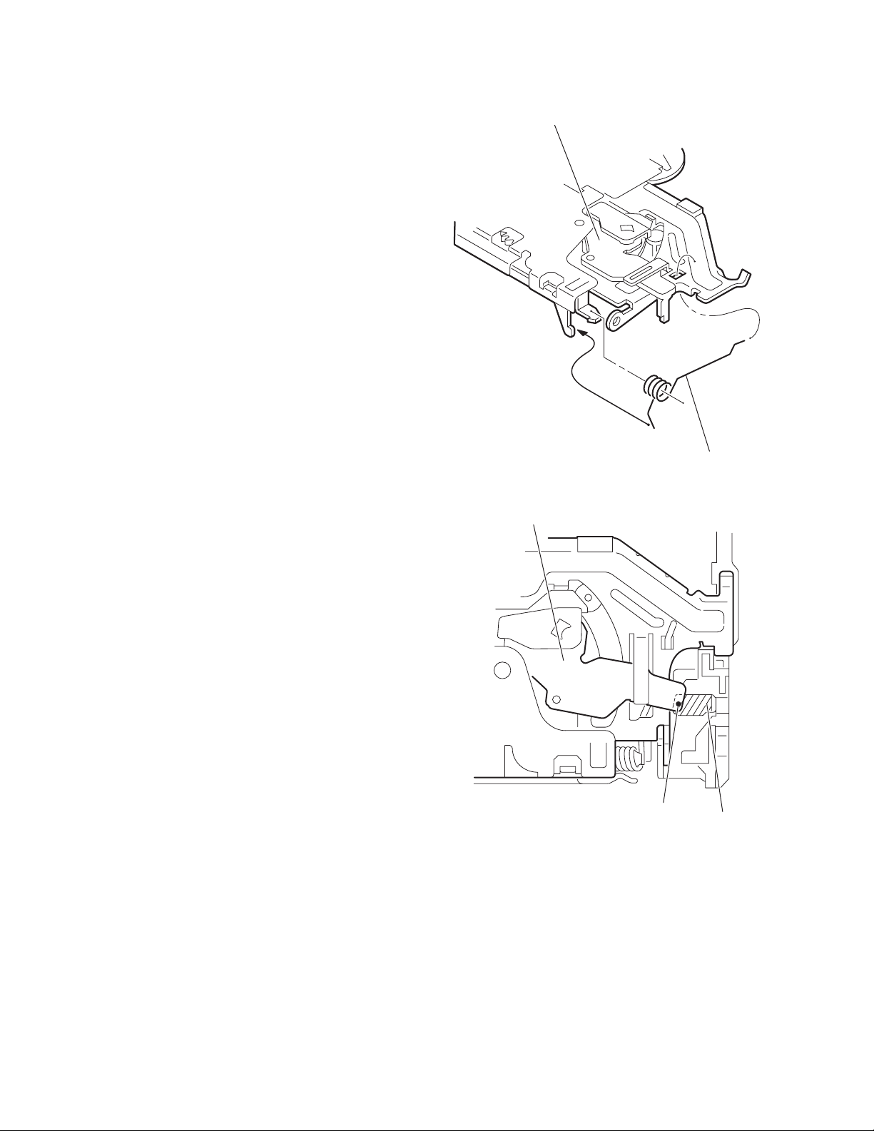
3.4.4 Removing the clamper unit
(See Figs.5 to 7)
• Remove the top cover and the mechanism section.
(1) Remove the clamper2 spring on the bottom of the mecha-
nism section. (See Figs.5.and 6.)
(2) Release the part d of the clamper spring from the bending
part of the chassis base assembly. (See Fig.7.)
(3) Move the clamper unit in the direction of the arrow and turn.
Release the two joints e and f, then remove the clamper
unit upward. (See Fig.5.)
Clamper unit
g
Clamper spring
Clamper spring
Chassis base assembly
d
Fig.7
f
Clamper2 spring
Chassis base assembly
Clamper2 spring
e
Fig.5
Chassis base assembly
Clamper unit
Fig.6
(No.MA101)1-25
Page 26
3.4.5 Reattaching the clamper unit
(See Figs.5 to 9)
(1) Attach the clamper spring to the clamper unit. (See Fig.8.)
(2) Move the clamper unit to set the side joints e and f to each
boss of the chassis base assembly. Make sure that part g
is inserted to the notch of the chassis base assembly. (See
Figs.5 and 9.)
(3) Move the part d of the clamper spring to the outside of the
bending part of the chassis base assembly. (See Fig.7.)
(4) Attach the clamper2 spring to the chassis base assembly.
(See Figs.5 and 6.)
Reference:
When reattaching, temporarily hook the end of the clamper
spring as shown in the figure to make the work easy. (See
Fig.8.)
Clamper unit
Clamper spring
Clamper unit
Fig.8
Fig.9
g
Notch
1-26 (No.MA101)
Page 27
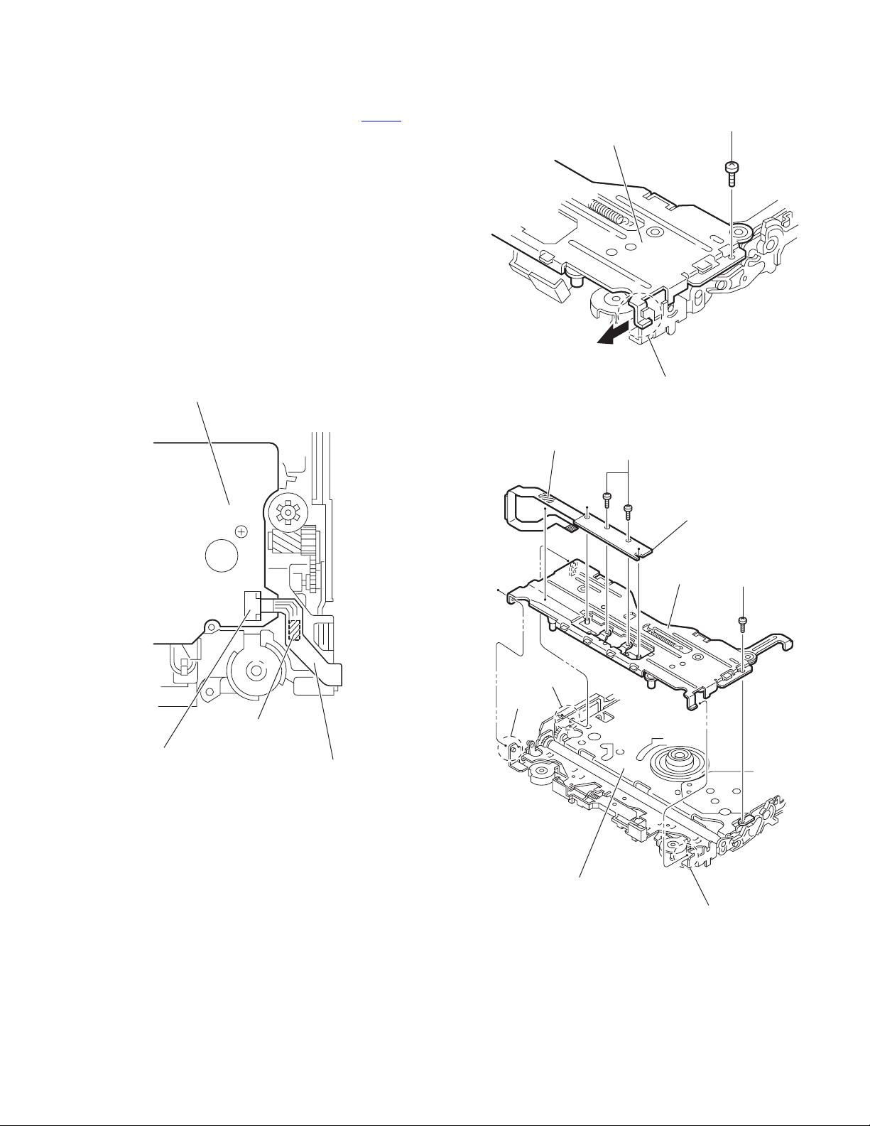
3.4.6 Removing the front unit
(See Figs.10 to 12)
• Remove the top cover and the mechanism section.
(1) Disconnect the flexible wire from connector CN202
front end board at the bottom of the body. (See Fig.10.)
(2) Remove the screw E attaching the front unit on the top of
the body. (See Figs.11 and 12.)
(3) Move the front unit toward the front to release joint h, and
release two joints i and j on the right side of the chassis
base assembly. Then remove the front unit upward. (See
Figs.11 and 12.)
(4) Remove the two screws F attaching the switch board. (See
Fig.12.)
Reference:
You can remove the switch board only without removing the
front unit.
Caution:
When reassembling, attach the flexible wire extending from
the switch board using the double tape. (See Figs.10 and 12.)
Front end board
on the
E
Front unit
h
Fig.11
CN202
Double tape
Fig.10
Flexible wire
Double tape
j
i
F
Switch board
Front unit
E
Chassis base assembly
Fig.12
h
(No.MA101)1-27
Page 28
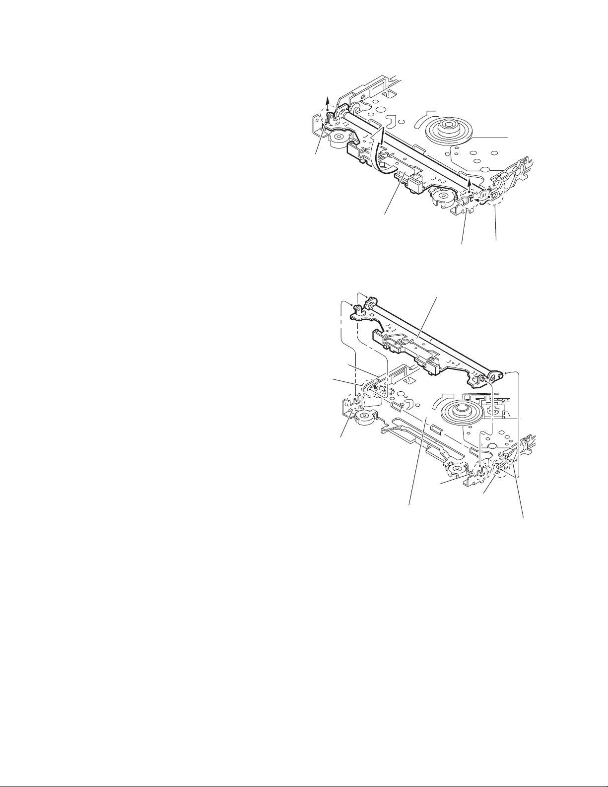
3.4.7 Removing the loading arm assembly.
(See Figs.13 and 14)
• Remove the top cover, the mechanism section and the front
unit.
(1) From the top of the body, move the loading arm assembly.
from the front side upward, and release the bosses from
the right and left joints k and m of the chassis base assembly.
(2) Release the boss from notch n of the connect arm on the
right side of the body, and release the boss from notch p of
the slide cam assembly on the left side.
m
Loading arm assembly
Slide cam
assembly
p
m
Fig.13
Loading arm assembly
k
Chassis base assembly
k
n
n
Connect arm
1-28 (No.MA101)
Fig.14
Page 29
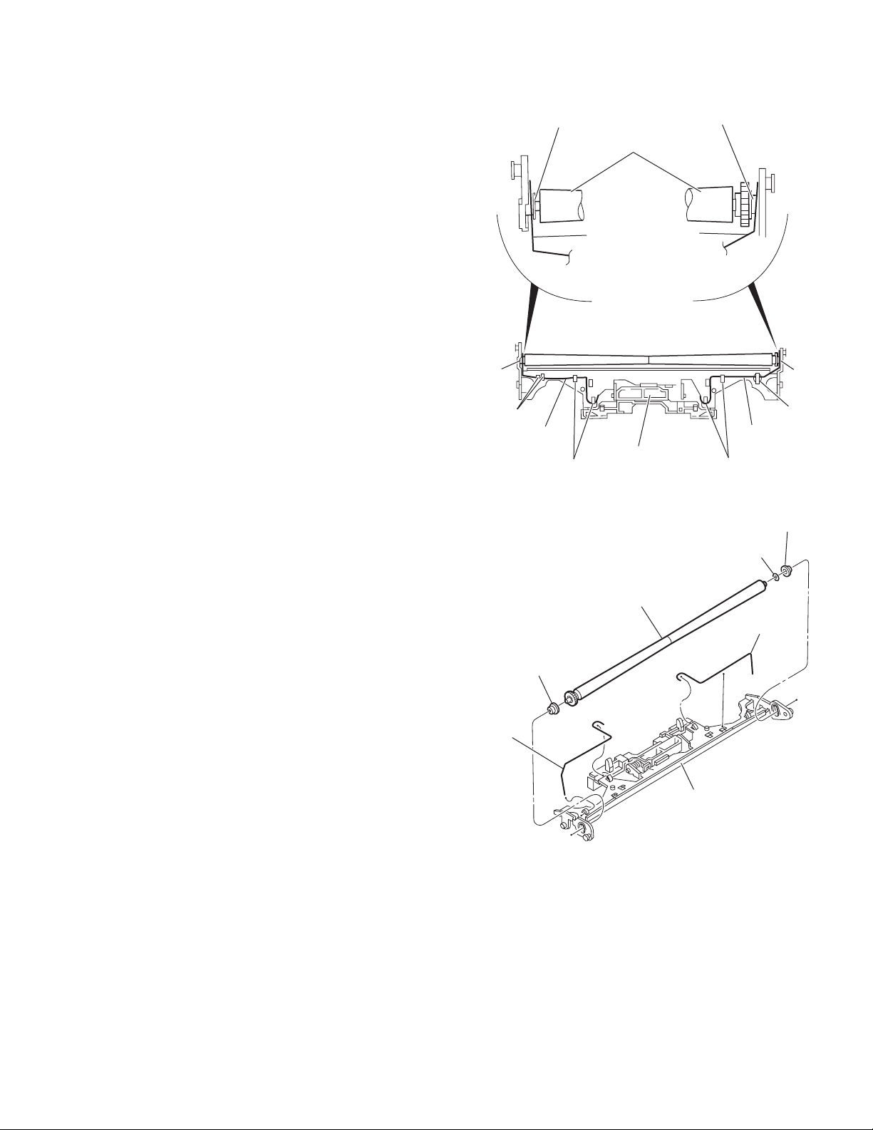
3.4.8 Removing the rod (L)(R)/roller assembly
(See Figs.15 and 16)
• Remove the top cover, the mechanism section, the front unit
and the loading arm assembly.
(1) Release the rod (L) and (R) from the joints q at the bottom
of the loading arm assembly. (See Fig.15.)
(2) Remove the roller assembly from the loading arm assem-
bly. (See Fig.16.)
(3) Remove the two collars and washer from the roller assem-
bly. (See Fig.16.)
Caution:
After attaching the loading arm assembly to the roller assembly, attach the rod (L) and (R). Attach the rods to the right and
left collars of the roller assembly. (See Figs.15.)
When reattaching the rod (L) and (R) to the loading arm assembly, engage each joints q as shown in Fig.15. As joints r
of the rod (L), let the rod through r before reattaching it.
Collar
Collar
Roller assembly
Rod(R) Rod(L)
q
q
Collar
Rod(L)
Rod(R)
Loading arm assembly
q
Fig.15
Roller assembly
q
r
Rod(L)
q
Collar
Washer
Rod(R)
Loading arm assembly
Fig.16
(No.MA101)1-29
Page 30
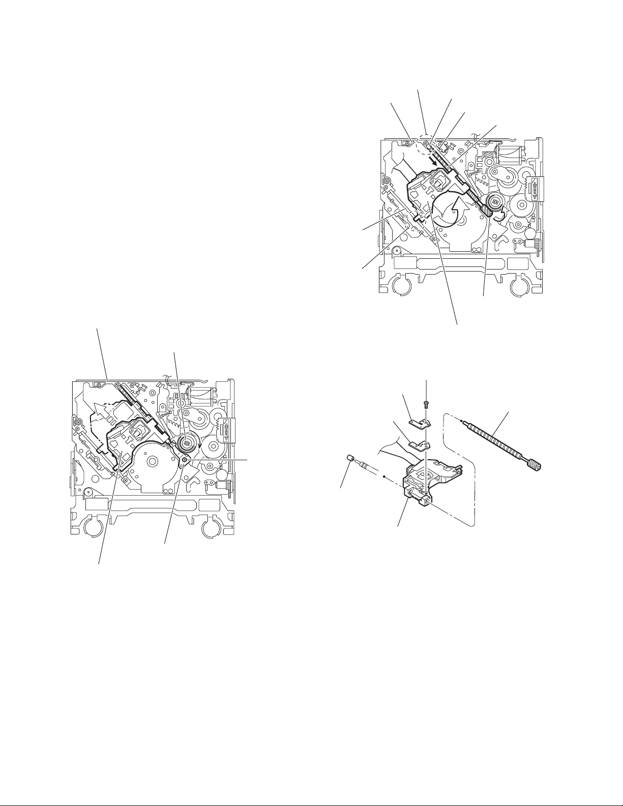
3.4.9 Removing the DVD pickup
(See Figs.17 to 19)
• Remove the front end board.
(1) From the bottom of the body, turn the feed gear in the di-
rection of the arrow to move the DVD pickup outwards.
(See Fig.17.)
(2) Remove the screw G attaching the thrust spring. (See
Fig.17.)
(3) Remove the DVD pickup assembly upward on the L.S.
gear side and release from sub shaft at joint s. Move the
lead screw of the DVD pickup assembly in the direction of
the arrow to release from joint t. (See Fig.18.)
(4) Remove the screw H attaching the rack spring/ rack plate
on the DVD pickup. (See Fig.19.)
(5) Pull out the lead screw. (See Fig.19.)
Caution:
• When releasing the lead screw, the L.S. collar comes off at
the end of the lead screw. When reassembling, reattach the
L.S. collar to the lead screw. (See Fig.19.)
• After reattaching the L.S. collar, reattach it to the point t of
the lead screw, and to the holder (M). Make sure that the
L.S. collar is set on the lod (M). (See Fig.18.)
• Perform adjustment after replacing the pickup.
Sub shaft
Holder(M)
s
t
L.S. collar
Lod(M)
Lead screw
L.S. gear
DVD mechanism assembly
Feed gear
Thrust spring
DVD pickup assembly
Fig.17
DVD pickup assembly
Fig.18
H
Rack spring
Lead screw
Rack plate
G
L.S. collar
DVD pickup
Fig.19
1-30 (No.MA101)
Page 31

3.4.10 Removing the spindle motor
(See Fig.20)
• Remove the front end board.
Remove the two screws J attaching the spindle motor on the
bottom of the body.
Caution:
Perform adjustment when reattaching the spindle motor.
DVD mechanism assembly
Spindle motor
J
Fig.20
(No.MA101)1-31
Page 32

3.4.11 Removing the feed motor assembly
r
(See Figs.21 and 22)
• Remove the front end board.
(1) Remove the feed TRI. spring on the bottom of the body.
(See Fig.21.)
(2) Remove the two screws K attaching the feed motor assem-
bly. (See Fig.21.)
(3) Remove the slit washer from the motor H. assembly and
pull out the worm wheel. (See Fig.22.)
(4) Remove the two screws L attaching the feed motor. (See
Fig.22.)
Feed TRI. spring
Slit washer
K
Feed motor assembly
Fig.21
Worm wheel
L
Motor H. assembly
Feed moto
Fig.22
1-32 (No.MA101)
Page 33

3.5 Hideaway unit section
3.5.1 Removing the top chassis
(See Figs.11 to 3)
(1) From the both sides of the main body, remove the four
screws A attaching the top chassis. (See Fig.1 and 2.)
(2) From the front side of the main body, remove the three
screws A, screw B and four screws C attaching the top
chassis. (See Fig.3.)
(3) Take out the top chassis from the main body in the direction
of the arrow. (See Figs.1 to 3.)
Top chassis
A
Fig.1
Top chassis
A
3.5.2 Removing the DSP board
(See Fig.4)
• Prior to performing the following procedures, remove the top
chassis.
(1) Remove the four screws D attaching the DSP board.
(2) Disconnect the connector CN901
board.
from the hideaway
Top chassis
CN901
A ACB
Fig.2
A
Fig.3
D
DSP board
Fig.4
Hideaway board
D
(No.MA101)1-33
Page 34

3.5.3 Removing the hideaway board
(See Figs.5 and 6)
• Prior to performing the following procedures, remove the top
chassis and DSP board.
(1) From the rear side of the main body, remove the four
screws E attaching the hideaway board. (See Fig.5.)
(2) From the top side of the main body, disconnect the wire
from the connector CN601
Fig.6.)
Reference:
After connecting the wire to the connector CN601
with the wire holder as before. (See Fig.6.)
(3) Remove the three screws F attaching the hideaway board.
(See Fig.6.)
(4) Take out the hideaway board from the bottom chassis as-
sembly.
on the hideaway board. (See
, fix it
E
Fig.5
CN601
Hideaway boardWire holder
Fig.6
F
1-34 (No.MA101)
Page 35

SECTION 4
ADJUSTMENT
4.1 Adjustment method
4.1.1 Test instruments required for adjustment
(1) Digital oscilloscope (100MHz)
(2) Jitter meter
(3) Digital tester
(4) Digital multi meter (For voltage measurement)
(5) Electric voltmeter
(6) Frequency counter
(7) Tracking offset meter
(8) Test Disc : VT501 or VT502
(9) Extension studs : STDV001-3P
(10) Extension cable : EXTAV70X-50PF
4.1.3 Connection method
When confirming the mechanism movement, connect each unit shown in Fig.1.
Connection procedure
(1) Connect the front panel assembly to the main board.
(2) Attach the extension studs to the DVD mechanism assembly.
(3) Connect the DVD mechanism assembly and the main board with a extension cable.
(4) Connect the hideaway unit and the main board with an attached cable.
(5) Fix the mechanism cover with tape in the top drive unit.
(6) Hang the mechanism cover on the rear bracket.
(7) Spread the wooden boards under the top drive unit in order to put it up shown in Fig.1.
(8) Attach the display unit to the top drive unit.
4.1.2 Standard measuring conditions
Power supply voltage DC14.4V(11 to 16V)
Load impedance 4Ω(2 Speakers connection)
Line output 20kΩ
Caution:
Be sure to attach the heat sink and rear bracket onto the power
amplifier IC and regulator IC respectively, before supply the
power. If voltage is applied without attaching these parts, the
power amplifier IC and regulator IC will be destroyed by heat.
(No.MA101)1-35
Page 36

4.1.4 Connecting diagram of extension cable
Fix it with tape.
Fix it with tape.
Extension cable
EXTAV70X-50PF
Fix it in a slit.
Monitor stability base
Example : Wood panel
(200mm x 170mm x 15mm)
Extension stud
STDV001-3P
Fig.1
1-36 (No.MA101)
Page 37

4.1.5 Adjustment method for jitter
After replacing the pickup, set the unit in the service mode to display a jitter value on the LCD. Confirm that the jitter value measured
with a jitter meter is within 12.0% of the jitter value displayed on the LCD. If it is within 12.0%, then adjustment is not necessary.
If the measured jitter value is outside the 12.0% tolerance range, perform the following adjustments.
4.1.5.1 Adjustment procedure
(1) Connect each unit shown in Fig.1.
(2) Set the unit to the service mode and display a jitter value (hex data) on the LCD.
(3) Turn each of the screws a, b and c, by a half-turn per step, in the direction that reduces the jitter value in order to minimize it.
(Do not turn a screw more than a half turn at a time, but adjust the screws in the cycle of a → b → c → a.)
(4) After completing the adjustment, secure the screws with screw lock paint.
c
b
a
Jitter value adjustment procedure (Pickup horizontal level adjustment relative to the DVD recording surface)(For the adjustment tool
use a 3 mm wrench and not a screwdriver, this procedure will make the adjustment easier.)
3 mm wrench
(No.MA101)1-37
Page 38

4.1.6 Jitter value conversion table
Load the test disc and set the unit to the service mode. A jitter value converted to the hex value is displayed on the LCD. Refer to the
corresponding decimal notation value shown in the following Jitter Conversion Table.
The adjustment is OK if the jitter value measured with a jitter meter is within 12.0% of the jitter value displayed on the LCD.
If the measured jitter value is outside the 12.0% tolerance range, adjust it to minimize the difference between the measured value and
the displayed value.
Indicated
on the LCD
20A7
2072
203D
2008
1FD2
1F9D
1F68
1F33
1EFE
1EC8
1E93
1E5E
1E29
1DF4
1DBE
1D89
1D54
1D1F
1CEA
1CB4
1C7F
1C4A
1C15
1BE0
1BAA
1B75
1B40
1B0B
1AD6
1AA0
1A6B
1A36
1A01
19CC
1996
1961
192C
18F7
JIT OUT
1957.98
1955.32
1952.66
1950
1947.34
1944.68
1942.02
1939.36
1936.7
1934.04
1931.38
1928.72
1926.06
1923.4
1920.74
1918.08
1915.42
1912.76
1910.1
1907.44
1904.78
1902.12
1899.46
1896.8
1894.14
1891.48
1888.82
1886.16
1883.5
1880.84
1878.18
1875.52
1872.86
1870.2
1867.54
1864.88
1862.22
1859.56
Jitter value
(%)
4.7
3818
4.8
3825
4.9
3832
5.0
3840
5.1
384D
5.2
385A
5.3
3867
5.4
3875
5.5
3882
5.6
388F
5.7
389D
5.8
38AA
5.9
38B7
6.0
38C5
6.1
38D2
6.2
38DF
6.3
38EC
6.4
38FA
6.5
3907
6.6
3914
6.7
3922
6.8
392F
6.9
393C
394A
7.0
3957
7.1
3964
7.2
3971
7.3
397F
7.4
398C
7.5
3999
7.6
39A7
7.7
39B4
7.8
39C1
7.9
39CF
8.0
39DC
8.1
39E9
8.2
39F6
8.3
3A04
8.4
Indicated
on the LCD
18C2
188C
1857
1822
17ED
17B8
1782
174D
1718
16E3
16AE
1678
1643
160E
15D9
15A4
156E
1539
1504
14CF
149A
1464
142F
13FA
13C5
1390
135A
1325
12F0
12BB
1286
1250
121B
11E6
11B1
117C
1146
1111
JIT OUT
1856.9
1854.24
1851.58
1848.92
1846.26
1843.6
1840.94
1838.28
1835.62
1832.96
1830.3
1827.64
1824.98
1822.32
1819.66
1817
1814.34
1811.68
1809.02
1806.36
1803.7
1801.04
1798.38
1795.72
1793.06
1790.4
1787.74
1785.08
1782.42
1779.76
1777.1
1774.44
1771.78
1769.12
1766.46
1763.8
1761.14
1758.48
Jitter value
(%)
3A11
8.5
3A1E
8.6
3A2C
8.7
3A39
8.8
3A46
8.9
3A54
9.0
3A61
9.1
3A6E
9.2
3A7B
9.3
3A89
9.4
3A96
9.5
3AA3
9.6
3AB1
9.7
3ABE
9.8
3ACB
9.9
3AD9
10.0
3AE6
10.1
3AF3
10.2
10.3
10.4
10.5
10.6
10.7
10.8
10.9
11.0
11.1
11.2
11.3
11.4
11.5
11.6
11.7
11.8
11.9
12.0
12.1
12.2
3B00
3B0E
3B1B
3B28
3B36
3B43
3B50
3B5E
3B6B
3B78
3B85
3B93
3BA0
3BAD
3BBB
3BC8
3BD5
3BE3
3BF0
3BFD
Indicated
on the LCD
10DC
10A7
1072
103C
1007
FD2
F9D
F68
F32
EFD
EC8
E93
E5E
E28
DF3
DBE
D89
D54
D1E
CE9
CB4
C7F
C4A
C14
BDF
BAA
B75
B40
B0A
AD5
AA0
A6B
A36
A00
9CB
996
961
92C
JIT OUT
1755.82
1753.16
1750.5
1747.84
1745.18
1742.52
1739.86
1737.2
1734.54
1731.88
1729.22
1726.56
1723.9
1721.24
1718.58
1715.92
1713.26
1710.6
1707.94
1705.28
1702.62
1699.96
1697.3
1694.64
1691.98
1689.32
1686.66
1684
1681.34
1678.68
1676.02
1673.36
1670.7
1668.04
1665.38
1662.72
1660.06
1657.4
Jitter value
(%)
3C0A
12.3
3C18
12.4
3C25
12.5
3C32
12.6
3C40
12.7
3C4D
12.8
3C5A
12.9
3C68
13.0
3C75
13.1
3C82
13.2
3C8F
13.3
3C9D
13.4
3CAA
13.5
3CB7
13.6
3CC5
13.7
3CD2
13.8
3CDF
13.9
3CED
14.0
3CFA
14.1
3D07
14.2
3D14
14.3
3D22
14.4
3D2F
14.5
3D3C
14.6
3D4A
14.7
3D57
14.8
3D64
14.9
3D72
15.0
3D7F
15.1
3D8C
15.2
3D99
15.3
3DA7
15.4
3DB4
15.5
3DC1
15.6
3DCF
15.7
3DDC
15.8
3DE9
15.9
3DF7
16.0
Calculation
1-38 (No.MA101)
Indicated on the LCD JIT OUT Jitter (%)
1AD6 1883.5 7.5
Page 39

4.1.7 Monitor adjustment
Procedure:
(1) Install a monitor to the main unit in the state that took off a display back panel.
(2) Switch on the main unit.
(3) According to the following chart, perform each adjustment.
Item Adjustment points Adjustment volume Adjustment value
Free Run Frequency adjustment
Touch Panel Sensor adjustment
Touch Panel Sensor adjustment
Touch Panel Sensor adjustment
Touch Panel Sensor adjustment
Screen right and left adjustment
TP431
TP425
TP426
TP427
TP428
Monitor screen
VR451
VR426
VR428
VR423
VR425
VR441
15.73kHz
DC1.1V㨪DV1.4V
DC1.1V㨪DV1.4V
DC1.1V㨪DV1.4V
DC1.1V㨪DV1.4V
Adjust it so that right and left position
becomes it centrally.
(No.MA101)1-39
Page 40

4.2 Service mode
4.2.1 Jigs and test instruments
(1) Test disc: VT-501, VT-502
(2) NTSC signal generator (E version only)
4.2.2 Standard input/output conditions
Power supply voltage: C14.4V (11V to 16V)
Load impedance: 4 Ω (2 Speakers connection)
Line output: 20k Ω
4.2.3 Service mode setting procedure
(The DVD does not need to be loaded before starting the following procedure.)
POWER/ATT
MODE
NEXT
PEVIOUS
1. Press a [POWER/ATT] button on a main unit and switch it on.
2. Press the [NEXT ] button and [PREVIOUS ] button simultaneously while pressing the [POWER/ATT]
button on the main unit.
3. This unit is set by a service mode and a service menu is displayed on the monitor..
Exchanging it operate a menu of a service mode with the [NEXT ] button and [PREVIOUS ] button.
Operate choice of a menu with a [MODE] button.
4. The indication of monitor return to the normal menu by pressing the [POWER/ATT] button on the main unit.
1-40 (No.MA101)
Page 41

4.2.4 Service mode menu
MENU AREA/REGION : Indication of destination and region
Service Mode Menu
MONITOR
TOUCH PANEL TEST
TOUCH PANEL CALIBRATION
AREA / REGION
VERSION
RUNNING MODE
CHECK MODE
EXPERT MODE
[NEXT] : UP [PREV] : DW [MODE] : ENT
This menu scrolls it with the [NEXT ]/[PREVIOUS ]
buttons.
AREA / REGION
HIDE - AREA
B / E - AREA
B / E - REGION
[MODE]
aa
Destination of hideaway
bb
Destination of DVD unit
cc
Region of DVD unit
(Note)
REGION CHANGE not using it by service.
VERSION : Indication of microcomputer version
VERSION
SYS - VER
F / E - VER
B / E - VER
SDK - VER
GUI - VER
MONITOR - VER
HIDE - VER
TV - VER
CDCH - VER
aaaa aa
bb
cc
dddddddddddddd
eeee
gggg
hhhh
kkkk
nnnn
: aa
: bb
: cc
: REGION CHANGE
: aaaa aa
: bb
: cc
: dddddddddddddd
: eeee
: gggg
: hhhh
: kkkk
: nnnn
System control microcomputer version
and ROM correction version
Front end microcomputer version
Back end microcomputer version
DVD back end SKD version
GUI version
Monitor version
Hideaway version
TV tuner version (In connection)
CD changer version (In connection)
RUNNING MODE (For use in various running tests)
(Note)
This mode not using it by service.
CHECK MODE : Check mode for DVD unit
CHECK MODE
CURRENT
JITTER
EJECT
CLOSE
NOMAL PLAY
OUT - TRACKING OFF
IN - TRACKING OFF
CD - LASER ON
[NEXT] : UP [PREV] : DW [MODE] : ENT
This menu scrolls it with the [NEXT ]/[PREVIOUS ] buttons.
A thing without CURRENT/JITTER indication is space.
See "4.2.5 DVD unit check mode" for details.
EXPERT MODE (DVD unit expert mode)
(Note)
This mode not using it by service.
TEMPERATURE : Data in the temperature sensor in the system controller/hideaway
is read every 5 seconds and displayed in hex numbers.
A
:
:
(No.MA101)1-41
Page 42

A
READ ERROR : Indication of an error history
LOADING/EJECT mechanism error
Monitor mechanism error
Changer error
"TOTAL ERROR :zzzzzz"
"E-n :xxyyyy"
"E0n :xxyyyy"
CLEAR ERROR : Clear error history
See "4.2.6 Error code table" for details.
Total error count
(A figure between 0 and 999999 is displayed.
1000000 or more is also displayed as 999999.)
(First five error codes)
Detailed error code
Error code
Counter
(Latest three error codes)
Detailed error code
Error code
Counter
The error history (LOADING/EJECT mechanism,
monitor mechanism and changer) is cleared.
The error history stored in the EEPROM is cleared.
(by writing 00h)
"COMPLETE" is displayed by a monitor after clear
was finished.
INITIALIZE : Initialize user set data
The system controller EEPROM is initialized except for the
error history.
INITIALIZE ALL : Initialize all data to the factory setting
The system controller EEPROM is initialized entirely.
MEMORY CHECK : Check indication is done with a normal screen.
MONITOR : Monitor service mode
MONITOR MECHA CHECK : Check mode of a monitor mechanism
DEMO SET UP : Change of a demonstration mode is done.
Touch Panel Test : GUI is set in the touch panel test mode
(Note)
This mode not using it by service.
See "4.2.7~4.2.9 Monitor adjustment" for details.
(Note)
This mode not using it by service.
Confirmation of a position gap of touch panel
Cancellation of this mode do long push of the
[POWER/ATT] button.
1-42 (No.MA101)
B
Page 43

B
4.2.5 DVD unit check mode
Touch Panel Calibration : Touch panel proofreading mode
81h 82h 83h
TOUCH PANEL CALIBRATION CODE 8Dh
84h 85h 86h
87h 88h 89h
See "4.2.10 Touch panel manual operation proofreading procedure" for details.
Push with a finger from 81h in turn.
After the proofreading end, push the [PREVIOUS ] button in order to switch
off the panel.
An effective key in a proofreading mode
[NEXT ]
[PREVIOUS ]
[POWER/ATT]
: 1. Monitor power supply ON
2. Touch panel proofreading mode ON
: 1. Touch panel proofreading mode OFF
2. Monitor power supply OFF
: Power supply OFF (Proofreading mode cancellation)
No. Key
NORMAL PLAY
1
Disc startup and through playback
DVD unit operation Remark
(Playback starts from the start position)
OUT
2
Tracking off the outermost position of CD
TRACKING
IN TRACKING
3
Tracking off the innermost position of CD
OFF
CD-LASER ON
4
5
DVD-LASER
CD_LD lights and laser current is displayed
DVD_LD lights and laser current is displayed
ON
DVDx1 JITTER
6
7
8
9
10
MODE
EEPROM
DATA+
EEPROM
DATAEEPROM
DATA CLEAR
DVD-SL
DVD x1 jitter measuring mode
(for use in mechanism adjustment)
Contents of EEPROM used by mechanism
(0x00 - 0xFF) displayed (FWD)
Contents of EEPROM used by mechanism
(0x00 - 0xFF) displayed
Initialization of EEPROM contents used by
the mechanism
Search & jitter measurement of the specified
position of DVD-SL
DVD-DL
11
12
13
14
15
16
(PARALLEL)
DVD-DL
(OPPOSITE)
PLAY
STOP
EJECT
CLOSE
Search & jitter measurement of the specified
position of parallel disc of the DVD-DL
Search & jitter measurement of the specified
position of opposite disc of DVD-DL
Disc playback
Disc stopped & LD-OFF
OPEN
CLOSE
Indication is displayed in hex numbers.
The check mode can be exited by pressing the [POWER] key.
For EF phase error
For EF phase error
: Laser current value
: Jitter value
: Laser current value
: Jitter value
: Laser current value
: Jitter value
: EEPROM address
: EEPROM contents
: EEPROM address
: EEPROM contents
: 0x00-0x02
(Position measured with VT-502)
: Jitter value
: 0x00-0x06
(Position measured with VT-501)
: Jitter value
: 0x00-0x06
(Position measured with VT-501)
: Jitter value
: Laser current value
: Jitter value
(No.MA101)1-43
Page 44

4.2.6 Error code table
(1) Error code table of LOADING/EJECT mechanism error
Error code (1 byte) Detailed error codes (2 bytes)
First byte [01] Eject error
[09] Loading error
Route No. (EJECT route No.)
-
1(2)
1(2)
First byte
Second byte
(Example) When a switch status error occurs during loading route 3 and the
switch status is L/L/H/H/H (00111B = 07H), the error code and
detailed error code become: [09 3207].
SW1/2/3/4
1,1,1,1
0,1,1,1
0,0,1,1
Higher 4 bits
Lower 4 bits
bit7
bit6,5
bit4
bit3
bit2
bit1
bit0
[Rest SW]
[0]
[0]
[0]
Route No. (Process of error occurrence)
Refer to charts 1.1 and 1.2.
Error type
[1] Time out
[2] Switch status defectiveness
[3] Swinging error
Disc type (0: 12 cm. 1: 8 cm)
Fixed at 0
SW1 status
SW2 status
SW3 status
SW4 status
REST SW status
Loading
No Disc
Disc insert
detection
Eject
No Disc
Eject
completion
Reload
Disc push in
2(2)
2(2)
2(2)
2(2)
3(1)
3(1)
Route No. (EJECT route No.)
-
1(2)
1(2)
2(2)
2(2)
3(1)
3(1)
Transition in the center loading (Similar to 12cm in the side loading)
0,0,0,1
0,0,1,1
0,1,1,1
1,1,1,1
1,1,1,0
1,1,1,0
Chart 1.1 12cm Disc switch status transition
SW1/2/3/4
1,1,1,1
0,1,1,1
0,0,1,1
0,1,1,1
1,1,1,1
1,1,1,0
1,1,1,0
Chart 1.2 8cm Disc switch status transition
[0]
[0]
[0]
[0]
[0]
[1]
[Rest SW]
[0]
[0]
[0]
[0]
[0]
[0]
[1]
Load completion
Loading
No Disc
Disc insert
detection
Load completion
Eject start
Eject
No Disc
Eject
completion
Eject start
Reload start
Load completion
Reload
Disc push in
Reload start
Load completion
1-44 (No.MA101)
Page 45

(2) Error code table of monitor mechanism error
Error code (1 byte)
Detailed error codes (2 bytes)
First byte [01] CLOSE error
[09] OPEN error
[0A] SLIDE error
(3) Error code table of changer
Outbreak condition
Tray extension
error
Tray retraction
error
Lifter raise
error
Lifter lower
error
Chuck error PLAY position time out
Unchuck error WAIT position time out
Eject error EJECT position time out
Initialize error Mechanism switch time out
Tray-in switch time out
(Tray-in switch Low,Tray-out switch High)
Tray-out switch time out
(Tray-in switch High,Tray-out switch High)
Tray-in switch time out
(Tray-in switch Low,Tray-out switch Low)
MAG-in switch Low to high
Tray-in switch time out
(Tray-in switch High,Tray-out switch Low)
Tray-out switch time out
(Tray-in switch High,Tray-out switch High)
Tray-in switch time out
(Tray-in switch Low,Tray-out switch Low)
MAG-in switch Low to high
WAIT position time out
WAIT position time out
WAIT position time out
WAIT position time out
WAIT position time out
WAIT position time out
PLAY position time out
PLAY position time out
WAIT position time out
WAIT position time out
EJECT position time out
MAG-in switch time out
Absolute position time out
First byte
Second byte
Higher 4 bits
Lower 4 bits
Higher 4 bits
Lower 4 bits
Tray motor does not work
Tray stops on the way
NG of Tray-in SW or other defect
Magazine removed when tray partly extend
Tray motor does not work
Tray stops on the way
NG of Tray-in SW or other defect
Magazine removed when tray partly extend
Position motor does not work
Position not stable in fine adjust mode
Other fault
Position motor does not work
Position not stable in fine adjust mode
Other fault
Position motor does not work
Position not stable in fine adjust mode
Other fault
Position motor does not work
Position not stable in fine adjust mode
Other fault
Position motor does not work
Eject position not attained
Magazine not ejected
Both Tray-in and Tray-out Low
Not stable at absolute position
Route No. (Process of error occurrence)
Error type
[1] Time out
[2] Pulse nothing
[3] Angle change nothing
[4] Switch status defectiveness
Motor status
(Motor output status in an error)
Bit7
Bit6
Bit5
Bit4
SW status
Bit3
Bit2
Bit1
Bit0
Details
0=Off/1=On
0=Slide/1=Angle
0=Minus/1=Plus
Fixed at 0
MO_DET
ANGSW
CLSW
Error
code
03
03
03
03
03
03
03
03
02
02
02
02
02
02
02
02
02
02
02
02
02
02
02
03
03
Detailed
error code
0011
0012
0013
0014
0016
0017
0018
0019
0021
0022
0023
0026
0027
0028
0031
0032
0033
0036
0037
0038
0041
0042
0043
0046
0047
(No.MA101)1-45
Page 46

4.2.7 Monitor adjustment (For J version)
1. Switch on the main unit and insert a test disc (VT-501 or VT-502).
Play a 3TR(100% color bar) of the test disc and pause it.
2. In a state of procedure 1, set the main unit in a service mode. (See "5.1.3 Service mode setting procedure".)
3. Color bar is displayed to the monitor by pushing [MODE] button after having done select of [MONITOR] of the
service menu with the [NEXT ] or [PREVIOUS ] buttons, and the following indication goes in mini-LCD of
the main unit.
CHROMA
PORT
[NEXT ] button
or
[PREVIOUS ] button
INIT
CCFL
Color adjustment
-------(EEPROM data read/write of a monitor microcomputer)
Port output setting (This mode not using it by service.)
--------
Monitor microcomputer shipment initialization setting
-------(This mode not using it by service.)
Backlight brightness setting (Fixed value B3)
--------
4. Select [CHROMA] and press the [MODE] button.
An address value and data value are displayed on the mini-LCD. (0 )
Press the center of the monitor to turn off the GUI screen.
5. Change data of each address with the [VOL+]/[VOL -] button while observing the color bar (Data value flashes
on and off in change operation.) and press the [MODE] button in order to write in data. (Adjust the fixed value
in the value of a following table. Besides it, set it in reference value and make a fine adjustment while observing
the monitor.)
No.
1
2
3
4
5
6
7
8
9
10
11
12
13
14
15
16
Address
Chrominance data
0
INPUT MODE/SW
1
PICTURE
2
COLOR
3
PHASE
4
CONTRAST
5
BRIGHT
6
GAMMA 0
7
GAMMA 1
8
OUT LIMIT
9
RGB AMPLITUDE
A
SUB-BRIGHT R
B
SUB-BRIGHT B
C
COM AMPLITUDE
D
COM BLANK LEV
E
DAC OUT
F
TINT
Minimum value
00
00
00
00
00
00
00
00
00
00
00
00
00
00
00
00
Maximum value
3F
FF
3F
FF
FF
FF
FF
FF
1F
FF
FF
FF
FF
1F
FF
FF
Fixed value Reference value
1C
2F
66
22
50
A5
3A
08
1F
7C
7F
60
D2
11
86
87
Cancellation of a test mode
Push the [STANDBY] key on the main unit.
1-46 (No.MA101)
Page 47

4.2.8 Monitor adjustment (For A/U version)
1. Switch on the main unit.
Press [FUNCTION] on the monitor and press [SETUP] next.
Select [DVD MENU] and selcct [PAL] of the [COLOR SYSTEM].
2. Insert a test disc (VT-501 or VT-502).
Play a 3TR(100% color bar) of the test disc and pause it.
3. In a state of procedure 2, set the main unit in a service mode. (See "5.1.3 Service mode setting procedure".)
4. Color bar is displayed to the monitor by pushing [MODE] button after having done select of [MONITOR] of the
service menu with the [NEXT ] or [PREVIOUS ] buttons, and the following indication goes in mini-LCD of
the main unit.
Press the center of the monitor to turn off the GUI screen.
CHROMA
PORT
[NEXT ] button
or
[PREVIOUS ] button
INIT
CCFL
Color adjustment
-------(EEPROM data read/write of a monitor microcomputer)
Port output setting (This mode not using it by service.)
--------
Monitor microcomputer shipment initialization setting
-------(This mode not using it by service.)
Backlight brightness setting (Fixed value B3)
--------
5. Select [CHROMA] and press the [MODE] button.
An address value and data value are displayed on the mini-LCD. (0 )
6. Change data of each address with the [VOL+]/[VOL -] button while observing the color bar (Data value flashes
on and off in change operation.) and press the [MODE] button in order to write in data. (Adjust the fixed value
in the value of a following table. Besides it, set it in reference value and make a fine adjustment while observing
the monitor.)
7. Press the [POWER/ATT] button of the main unit, and switch it off.
8. Switch on the main unit again.
Selcct [NTSC] of the [COLOR SYSTEM].
9. Repeat the adjustment mentioned above.
10. Press the [POWER/ATT] button of the main unit and this adjustment is complete.
No.
1
2
3
4
5
6
7
8
9
10
11
12
13
14
15
16
Address
Chrominance data
0
INPUT MODE/SW
1
PICTURE
2
COLOR
3
PHASE
4
CONTRAST
5
BRIGHT
6
GAMMA 0
7
GAMMA 1
8
OUT LIMIT
9
RGB AMPLITUDE
A
SUB-BRIGHT R
B
SUB-BRIGHT B
C
COM AMPLITUDE
D
COM BLANK LEV
E
DAC OUT
F
TINT
Minimum value
00
00
00
00
00
00
00
00
00
00
00
00
00
00
00
00
Cancellation of a test mode
Push the [STANDBY] key on the main unit.
Maximum value
3F
FF
3F
FF
FF
FF
FF
FF
1F
FF
FF
FF
FF
1F
FF
FF
Fixed value Reference value
PAL NTSC PAL NTSC
1C
2F
66
22
50
7F
60
D2
86
87
A5
3A
08
1F
7C
11
1E
2F
66
22
50
A5
3A
08
1F
7C
7F
60
D2
11
86
87
(No.MA101)1-47
Page 48

4.2.9 Monitor adjustment (For E version)
[PAL screen adjustment]
1. Switch on the main unit and insert a test disc (VT-501 or VT-502).
Play a 3TR(100% color bar) of the test disc and pause it.
2. In a state of procedure 1, set the main unit in a service mode. (See "5.1.3 Service mode setting procedure".)
3. Color bar is displayed to the monitor by pushing [MODE] button after having done select of [MONITOR] of the
service menu with the [NEXT ] or [PREVIOUS ] buttons, and the following indication goes in mini-LCD of
the main unit.
Press the center of the monitor to turn off the GUI screen.
CHROMA
PORT
[NEXT ] button
or
[PREVIOUS ] button
INIT
CCFL
Color adjustment
-------(EEPROM data read/write of a monitor microcomputer)
Port output setting (This mode not using it by service.)
--------
Monitor microcomputer shipment initialization setting
-------(This mode not using it by service.)
Backlight brightness setting (Fixed value B3)
--------
4. Select [CHROMA] and press the [MODE] button.
An address value and data value are displayed on the mini-LCD. (0 )
5. Change data of each address with the [VOL+]/[VOL -] button while observing the color bar (Data value flashes
on and off in change operation.) and press the [MODE] button in order to write in data. (Adjust the fixed value
in the value of a following table. Besides it, set it in reference value and make a fine adjustment while observing
the monitor.)
6. Press the [POWER/ATT] button of the main unit, and switch it off.
No.
1
2
3
4
5
6
7
8
9
10
11
12
13
14
15
16
Address
Chrominance data
0
INPUT MODE/SW
1
PICTURE
2
COLOR
3
PHASE
4
CONTRAST
5
BRIGHT
6
GAMMA 0
7
GAMMA 1
8
OUT LIMIT
9
RGB AMPLITUDE
A
SUB-BRIGHT R
B
SUB-BRIGHT B
C
COM AMPLITUDE
D
COM BLANK LEV
E
DAC OUT
F
TINT
Minimum value
00
00
00
00
00
00
00
00
00
00
00
00
00
00
00
00
Maximum value
3F
FF
3F
FF
FF
FF
FF
FF
1F
FF
FF
FF
FF
1F
FF
FF
Fixed value Reference value
1E
2F
66
22
50
A5
3A
08
1F
7C
7F
60
D2
11
86
87
Cancellation of a test mode
Push the [STANDBY] key on the main unit.
1-48 (No.MA101)
Page 49

[NTSC screen adjustment]
1. Switch on the main unit.
Input a NTSC signal into a AV1 input terminal.
(In case of a DVD player, insert the test disc VT-501 and play the 3TR.)
In the case of other sources, do color confirmation with the image.
2. In a state of procedure 1, set the main unit in a service mode. (See "5.1.3 Service mode setting procedure".)
3. Color bar is displayed to the monitor by pushing [MODE] button after having done select of [MONITOR] of the
service menu with the [NEXT ] or [PREVIOUS ] buttons, and the following indication goes in mini-LCD of
the main unit.
Press the center of the monitor to turn off the GUI screen.
CHROMA
PORT
[NEXT ] button
or
[PREVIOUS ] button
INIT
CCFL
Color adjustment
-------(EEPROM data read/write of a monitor microcomputer)
Port output setting (This mode not using it by service.)
--------
Monitor microcomputer shipment initialization setting
-------(This mode not using it by service.)
Backlight brightness setting (Fixed value B3)
--------
4. Select [CHROMA] and press the [MODE] button.
An address value and data value are displayed on the mini-LCD. (0 )
5. Change data of each address with the [VOL+]/[VOL -] button while observing the color bar (Data value flashes
on and off in change operation.) and press the [MODE] button in order to write in data. (Adjust the fixed value
in the value of a following table. Besides it, set it in reference value and make a fine adjustment while observing
the monitor.)
6. Press the [POWER/ATT] button of the main unit, and switch it off.
No.
1
2
3
4
5
6
7
8
9
10
11
12
13
14
15
16
Address
Chrominance data
0
INPUT MODE/SW
1
PICTURE
2
COLOR
3
PHASE
4
CONTRAST
5
BRIGHT
6
GAMMA 0
7
GAMMA 1
8
OUT LIMIT
9
RGB AMPLITUDE
A
SUB-BRIGHT R
B
SUB-BRIGHT B
C
COM AMPLITUDE
D
COM BLANK LEV
E
DAC OUT
F
TINT
Minimum value
00
00
00
00
00
00
00
00
00
00
00
00
00
00
00
00
Maximum value
3F
FF
3F
FF
FF
FF
FF
FF
1F
FF
FF
FF
FF
1F
FF
FF
Fixed value Reference value
1C
2F
66
22
50
A5
3A
08
1F
7C
7F
60
D2
11
86
87
Cancellation of a test mode
Push the [STANDBY] key on the main unit.
(No.MA101)1-49
Page 50

4.2.10 Touch panel manual operation proofreading procedure
Procedure 1 Proofreading
(1) Set the main unit in a touch panel proofreading mode.
(2) Push the center of the figure of a cross in a circle of green (81h to 89h) on the panel in turn.
a) Push for each 3 points of the upper part of 81h and 82h and 83h with a thumb of the right hand (or, left hand) on the
panel from a direction.
b) Push 84h with a thumb of the left hand from the left course.
c) Push 85h with the middle finger of the right hand or the middle finger of the left hand from center direction.
d) Push 86h with a thumb of the right hand from the right course.
e) Push for each 3 points of the lower part of 87h and 88h and 89h with a thumb of the right hand (or, left hand) under the
panel from a direction.
(3) When proofreading was completed normally, OK is displayed.
(4) Repeat since a beginning when NG was displayed.
(5) After proofreading completion, turn off the power supply and confirm it again.
Procedure 2 Confirmation
(1) Switch on the main unit and turn the main unit into normal movement.
(2) Push a screen key of GUI and set the main unit in the mode that "NAME" is displayed in the right bottom.
(3) Push "NAME" in order to let a screen display a keyboard of British number and push all keys in order to confirm misrecognition.
(4) When misrecognition occurred, proofread it since a beginning.
1-50 (No.MA101)
Page 51

SECTION 5
TROUBLESHOOTING
5.1 AV bus cable between main unit and hideaway unit
20
16
12
6
17
13
20
16
12
7
1
QAM0612-002 6000 mm
QAM0612-001 2500 mm
6
17
13
7
1
10
1
2
3
4
5
6
7
8
9
RESET
P-ON
SDI
SDO
GND
HPAL
SPDIF
NC
DVDAR-GND
DVDAL-GND
Black
White
Light green
Brown
Yellow
Blue
Natural
Orange
Black(Tube)
Black(Tube)
11
12
13
14
15
16
17
18
19
20
NC
HPA-GND
SPDIFGND
DVDAR
DVDAL
HPAR
VIDEO-OUT
VIDEO-GND
VIDEO-IN
VIDEO-GND
Pink
Black(Tube)
Black(Tube)
Red
Green
Purple
Natural
Black(Tube)
Natural
Black(Tube)
(No.MA101)1-51
Page 52

5.2 Center speaker / rear camera cord
3
BK
BK/WH
4
1 VI/WH
3 BK
4 BK/WH
5.3 Extention aerial cord
PLUG
VI/WH
1
2
NC
BK
VI
2500 mm
BLACK
VIOLET
WH
WHITE
BACK
CAMERA
CENTER
JACK
2593 mm
1-52 (No.MA101)
Page 53

5.4 Power cord for main unit (for KD-AV7001E,KD-AV7001EU)
4 BK
5
OR/WH
EARTH
6
1 YL
4 BK
2 RD
1 YL
2 RD
CORE
3
Fuse 250V-6.3A
F6.3A
BK
BL
WH
Black
Blue
White
MEMORY
GND
ACC
RD
YL
Red
Yellow
BL/WH
5
OR/WH
6
7 RD
8 BK
1 NC
2 BR
3 NC
4 YL
4 YL
8 BK
7 RD
5 OR/WH
3 CORE
6 EARTH
GY
MEMORY
GND
ACC
ILL
REMOTE
TEL
ILL
REMOTE
TEL
O.E.REMOTE
ILLUMINATION
CONTROL
REMOTE
OUT
TEL MUTING
Memory back up battery+
Ground
ACC line
Illumination control
Remote out
Telephone muting
6 OR/WH
5 BL/WH
2 BR
O.E.REMOTE
(No.MA101)1-53
Page 54

5.5 Power cord for Hideaway unit (for KD-AV7001E,KD-AV7001EU)
1 BK
3 BL/WH
5 VI
6 VI/BK
7 GN/BK
8 GN
9 WH
10 WH/BK
11 GY/BK
12 GY
13 BR
16 YL
14 L.GN
8 GN
GN/BK
7
VI/WH
6
5 VI
4 NC
3
BL/WH
2 NC
1 BK
1000 mm
9 WH
10
WH/BK
GY/BK
11
12 GY
13 BR
14 L.GN
15 NC
16 YL
GND
GROUND
REMOTE
TEL
MEMORY
PARKING
RR+
RR-
RL-
RL+
FL+
FL-
FR-
FR+
BK
BL
WH
L.GN
2500 mm
Black
Blue
White
Light Green
GN
VI
GY
YL
BR
Green
Violet
Gray
Yellow
Brown
1 VI
3 GY
5 WH
7 GN
REMOTE
OUT
ޓTEL
MUTING
PARKING
BRAKE
1 VI
2 VI/BK
8 GN/BK
7 GN
5 WH
6 WH/BK
4 GY/BK
3 GY
2
4
6
8
VI/WH
GY/BK
WH/BK
GN/BK
POWER LEAD/
MEMORY BACK UP
4000 mm
1-54 (No.MA101)
MEMORY
GND
REMOTE
PARKING
TEL
RR
FR
RL
FL
Memory back up battery+
Ground
Remote out
Parking brake
Telephone muting
Rear Right
Front Right
Rear Left
Front Left
Page 55

5.6 Power cord for main unit (for KD-AV7000J,KD-AV7005U,KD-AV7005UN,KD-AV7008A)
4 BK
OR/WH
5
6 NC
1 YL
2 RD
4 BK
5 OR/WH
1 YL
2 RD
3 NC
BK
BL
WH
Black
Blue
White
POWER LEAD/
MEMORY BACK UP
POWER LEAD
GROUND
ILLUMINATION
CONTROL
RD
YL
Fuse 250V-6A
6A
Red
Yellow
500 mm
(No.MA101)1-55
Page 56

5.7 Power cord for hideway unit (for KD-AV7000J)
1 BK
3 BL/WH
4 BL
5 VI
6 VI/BK
7 GN/BK
8 GN
9 WH
10 WH/BK
11 GY/BK
12 GY
16 YL
14 L.GN
8 GN
GN/BK
7
VI/WH
6
5 VI
4 BL
3
BL/WH
2 NC
1 BK
9 WH
10
11
12 GY
13 NC
14 L.GN
15 NC
16 YL
1000 mm
WH/BK
GY/BK
GROUND
GND
REMOTE
ANT
RR+
RR-
RL-
RL+
FL+
FL-
FR-
FR+
MEMORY
PARKING
BK
BL
WH
L.GN
2500 mm
Black
Blue
White
Light Green
GN
VI
GY
YL
Green
Violet
Gray
Yellow
REMOTE
OUT
POWER
ANTENNA
PARKING
BRAKE
POWER LEAD/
MEMORY BACK UP
MEMORY
GND
REMOTE
PARKING
ANT
RR
FR
RL
FL
4000 mm
Memory back up battery+
Ground
Remote out
Parking brake
Power antenna
Rear Right
Front Right
Rear Left
Front Left
1-56 (No.MA101)
Page 57

5.8 Power cord for hideaway unit (for KD-AV7005U,KD-AV7005UN,KD-AV7008A)
1 BK
3 BL/WH
4 BL
5 VI
6 VI/BK
7 GN/BK
8 GN
9 WH
10 WH/BK
11 GY/BK
12 GY
13 BR
16 YL
14 L.GN
8 GN
GN/BK
7
VI/WH
6
5 VI
4 BL
3
BL/WH
2 NC
1 BK
1000 mm
9 WH
10
WH/BK
GY/BK
11
12 GY
13 BR
14 L.GN
15 NC
16 YL
GROUND
GND
REMOTE
ANT
RR+
RR-
RL-
RL+
FL+
FL-
FR-
FR+
TEL
MEMORY
PARKING
2500 mm
BK
BL
WH
L.GN
Black
Blue
White
Light Green
GN
VI
GY
YL
BR
Green
Violet
Gray
Yellow
Brown
REMOTE
OUT
POWER
ANTENNA
TEL MUTING
PARKING
BRAKE
POWER LEAD/
MEMORY BACK UP
4000 mm
MEMORY
GND
REMOTE
PARKING
TEL
ANT
RR
FR
RL
FL
Memory back up battery+
Ground
Remote out
Parking brake
Telephone muting
Power antenna
Rear Right
Front Right
Rear Left
Front Left
(No.MA101)1-57
Page 58

5.9 The initialization method of a top drive unit
(1) When top drive unit is exchanged.
(2) When exchange or gear is shifted for gear by repair of top drive unit.
(3) When Monitor Does Not Open and Close (when it Moves Manually Forcibly)
Please initialize at the above time.
Initialization procedure
TI button is detached after detaching reset button which pushes reset button, pushing TI button.
* Even if it initializes by 3., when not being repaired, repair of a top drive unit and exchange are required.
1-58 (No.MA101)
Page 59

(No.MA101)1-59
Page 60

Victor Company of Japan, Limited
AV & MULTIMEDIA COMPANY CAR ELECTRONICS CATEGORY 10-1,1chome,Ohwatari-machi,Maebashi-city,371-8543,Japan
(No.MA101)
Printed in Japan
VPT
Page 61

PARTS LIST
[ KD-AV7000 ][ KD-AV7001 ]
[ KD-AV7005 ][ KD-AV7008 ]
[ KV-MAV7001 ][ KV-MAV7002 ]
* All printed circuit boards and its assemblies are not available as service parts.
KD-AV7000
Area suffix
J ------------- Northern America
KD-AV7005
Area suffix
UN --------------------------Asean
U -------------------- Other Areas
KD-AV7001
Area suffix
E ------------- Southern Europe
EU ------------------------- Turkey
KD-AV7008
Area suffix
A ------------------------ Australia
KV-MAV7001,KV-MAV7002
Area suffix
U -------------------- Other Areas
No.MA101
- Contents -
Exploded view of general assembly and parts list (Block No.M1)
Hideaway assembly and parts list (Block No.M2)
DVD mechanism assembly and parts list (Block No.MJ)
Electrical parts list (Block No.01~06)
Packing materials and accessories parts list (Block No.M3)
Monitor assembly and parts list (Block No.M4) (KV-MAV7001,KV-MAV7002)
Electrical parts list (Block No.07) (KV-MAV7001,KV-MAV7002)
Packing materials and accessories parts list (Block No.M5)
(KV-MAV7001,KV-MAV7002)
3- 2
3- 7
3- 9
3-12
3-37
3-39
3-41
3-47
3-1
Page 62

Exploded view of general assembly and parts list
5
Block No.
MMM1
39
32
Display board
39
101
b
35
37
Monitor switch board
40
100
39
a
20
20
d
20
33
117
17
33
33
38
113
38
49
51
48
32
c
28
99
29
31
e
49
29
38
27
22
14
38
23
29
131
Main board
59
118
36
42
24
25
30
26
e
24
30
a
d
c
18
18
136
19
41
21
134
18
16
43
b
Switch board
18
91
91
132
133
91
13
66
72
71
69
34
67
15
92
75
12
78
90
87
84
88
80
79
76
81
77
n
86
98
89
93
83
g
96
94
95
106
97
82
112
85
g
91
54
f
53
135
92
75
44
3-2
74
73
70
68
Page 63

47
ard
59
51
48
118
49
59
121
50
58
A
46
47
62
62
62
51
64
Display Drive unit
m
63
k
63
1
102
105
11
104
h
5
10
6
k
Display Drive unit
m
n
63
6
8
6
9
2
3
3
111
60
107
110
65
7
4
61
Connect board
108
j
A
109
60
60
103
120
j
h
57
63
116
119
59
16 0.1
132
58
f
59
122
16 0.1
126
133
1
45
122
128
91
123
53
54
Top view
52
55
135
127
129
125
124
44
115
130
114
56
130
3-3
Page 64

General Assembly
Block No. [M][1][M][M]
Symbol No. Part No. Part Name Description Local
1 LV10946-004A TOP DRIVE UNIT
2 LV34862-002A F.P.C.GUIDE
3 QYSPSPT2030ZA SCREW M2 x 3mm(x2)
4 LV43745-001A SPECIAL SCREW
5 LV34867-001A PWB BASE
6 LV44159-001A MINI SCREW (x3)
7 LV43747-001A INSULATOR
8 LV43748-002A CN GUIDE
9 QYSSSFT1760ZA TAP SCREW M1.7 x 6mm(x2)
10 LV43749-001A INSULATOR BKT
11 VKZ4539-055 MINI SCREW
12 LV10891-020A DISPLAY PANEL AV7000J
12 LV10891-014A DISPLAY PANEL AV7001E,AV7001EU
12 LV10891-015A DISPLAY PANEL AV7005U,AV7005UN
12 LV10891-016A DISPLAY PANEL AV7008A
13 GE40204-002A JVC BADGE AV7005U,AV7005UN
13 GE40204-001A JVC BADGE AV7000J,AV7001E,AV7001EU,AV7008A
14 LV34872-002A BLIND SHEET
15 LV34873-006A OPEN BUTTON AV7005U,AV7005UN
15 LV34873-005A OPEN BUTTON AV7000J,AV7001E,AV7001EU,AV7008A
16 LV34874-004A ANGLE BUTTON AV7005U,AV7005UN
16 LV34874-003A ANGLE BUTTON AV7000J,AV7001E,AV7001EU,AV7008A
17 LV21682-006A DISP BACK PANEL
18 LV43819-004A SPECAL SCREW (x6) AV7005U,AV7005UN
18 LV43819-003A SPECAL SCREW (x6) AV7000J,AV7001E,AV7001EU,AV7008A
19 LV43753-003A REINFORCE BKT
20 QYSDSF2008MA TAP SCREW M2 x 8mm(x3)
21 LV10918-003A LOCK BASE
22 LV34875-004A LOCK COVER(L)
23 LV34876-003A LOCK COVER(R)
24 LV43754-001A LOCK SPRING (x2)
25 LV43755-002A STOPPER(L)
26 LV43756-002A STOPPER(R)
27 LV34877-002A SLIDER ASSY
28 LV43758-001A TEN SPRING
29 LV43759-002A SPECIAL SCREW (x3) AV7001EU,AV7005UN
29 LV43759-001A SPECIAL SCREW (x3) AV7000J,AV7001E,AV7005U,AV7008A
30 LV43760-004A TOR SPRING (x2)
31 LV34879-002A DISP REAR COVER AV7005U,AV7005UN
31 LV34879-001A DISP REAR COVER AV7000J,AV7001E,AV7001EU,AV7008A
32 LV40849-013A SPACER(R) (x2)
33 LV43819-004A SPECAL SCREW (x3) AV7005U,AV7005UN
33 LV43819-003A SPECAL SCREW (x3) AV7000J,AV7001E,AV7001EU,AV7008A
34 LV43761-002A DISPLAY LENS AV7005U,AV7005UN
34 LV43761-001A DISPLAY LENS AV7000J,AV7001E,AV7001EU,AV7008A
35 LV34880-001A DISP SHEET(1)
36 LV34881-001A DISP SHEET(2)
37 LV35303-001A DISP SHEET(3)
38 QYSDSF2008MA TAP SCREW M2 x 8mm(x8)
39 LV40847-011A SPACER(H) (x3)
40 QLD0336-001 LCD MODULE
41 LV35393-006A SHIELDING SHEET
42 LV44247-001A SHIELD TIGHT
43 LV43973-006A SHIELD TIGHT
44 LV34885-006A B.CHASSIS ASSY
45 LV34886-002A INSULATER
46 LV34889-001A MECHA BKT
47 QYSDST2604ZA TAP SCREW M2.6 x 4mm(x2)
48 LV21684-002A MECHA COVER
49 LV44153-002A SPACER (x2)
50 QYSDST2604ZA TAP SCREW M2.6 x 4mm
51 QYSDST2606MA TAP SCREW M2.6 x 6mm(x2)
52 LV44037-001A COOLING RUBBER
53 LV44037-002A COOLING RUBBER
54 LV44037-003A COOLING RUBBER
55 LV35450-001A HEAT SINK
56 LV43792-001A FPC COVER
57 LV34892-004A REAR BKT
58 QYSDSP2004ZA SCREW M2 x 4mm(x2)
59 QYSDST2604ZA TAP SCREW M2.6 x 4mm(x5)
60 LV41200-004A SPECIAL SCREW (x3)
61 LV41200-004A SPECIAL SCREW
62 LV41200-004A SPECIAL SCREW (x3)
63 LV41200-004A SPECIAL SCREW (x4)
3-4
Page 65

Symbol No. Part No. Part Name Description Local
64 LV40847-012A SPACER(H)
65 LV41200-004A SPECIAL SCREW
66 LV10893-002A DETACH PANEL AV7005U,AV7005UN
66 LV10893-001A DETACH PANEL AV7000J,AV7001E,AV7001EU,AV7008A
67 LV34893-001A BACK PANEL(L)
68 LV34894-001A BACK PANEL(R)
69 LV21686-002A BUTTON(L) AV7001E,AV7001EU
69 LV21686-001A BUTTON(L) AV7000J,AV7005U,AV7005UN,AV7008A
70 LV21687-001A BUTTON(R)
71 LV34895-001A DETACH BUTTON
72 LV43772-001A COM SP
73 LV34896-001A REMOTE LENS
74 LV34897-006A FINDER AV7001E,AV7001EU
74 LV34897-008A FINDER AV7005U,AV7005UN
74 LV34897-005A FINDER AV7000J,AV7008A
75 VKZ4777-009 MINI SCREW (x4) AV7001EU,AV7005UN
75 VKZ4777-004 MINI SCREW (x4) AV7000J,AV7001E,AV7005U,AV7008A
76 LV21688-001A BUTTON LWR(L)
77 LV21689-001A BUTTON LWR(R)
78 LV10895-006A FRONT PANEL AV7005U,AV7005UN
78 LV10895-004A FRONT PANEL AV7000J,AV7001E,AV7001EU,AV7008A
79 LV34898-001A DETACH LEVER
80 LV21690-001A DISC GUIDE
81 LV40847-014A SPACER(H) (x2)
82 LV34899-001A LOCK LEVER(1)
83 LV34900-001A LOCK LEVER(2)
84 LV34901-001A LOCK LEVER(3)
85 LV34902-002A L.LEVER BKT ASS
86 QYREE1500X E RING M1.5
87 LV43769-001A TOR SP(1)
88 LV43770-001A TOR SP(2)
89 LV43771-002A TOR SP(3)
90 LV43776-002A BLIND
91 VKZ4777-007 MINI SCREW (x4) AV7001EU,AV7005UN
91 VKZ4777-002 MINI SCREW (x4) AV7000J,AV7001E,AV7005U,AV7008A
92 LV44159-001A MINI SCREW (x2)
93 LV34905-002A LCD COVER
94 LV34906-003A LCD LENS
95 LV43774-001A LCD FILTER
96 LV43775-003A LENS SHEET
97 QLD0335-001 LCD MODULE
98 QNZ0717-001 RUBBER CONNE
99 LV44223-001A INSULATOR
100 LV35750-003A SHIELD SHEET
101 QUQ105-0805AB FFC WIRE 8pin 5cm
102 QUQ105-5011AB FFC WIRE 50pin 11cm
103 VYSH101-009 SPACER
104 QQR1641-001 FERRITE CORE
105 LV40847-015A SPACER(H)
106 QUQ105-1304AB FFC WIRE 13pin 4cm
107 QAL0583-001 FPC
108 QQR1641-001 FERRITE CORE
109 LV40847-015A SPACER(H)
110 LV44218-002A SUPPORT SHEET
111 LV44218-003A SUPPORT SHEET
112 LV35137-001A NAME PLATE AV7000J
112 LV35138-002A NAME PLATE AV7001E,AV7001EU
112 LV35139-001A NAME PLATE AV7005U,AV7005UN
112 LV35140-001A NAME PLATE AV7008A
113 LV35683-001A NAME PLATE AV7000J
113 LV35684-001A NAME PLATE AV7001E,AV7001EU
113 LV35685-001A NAME PLATE AV7005U,AV7005UN
113 LV35686-001A NAME PLATE AV7008A
114 LV41843-002A LASER CAUTION AV7001E,AV7001EU
115 LV35183-001A LABEL(DVD) AV7000J
115 LV35183-006A LABEL(DVD) AV7001E,AV7001EU
115 LV35183-003A LABEL(DVD) AV7005U,AV7005UN
115 LV35183-004A LABEL(DVD) AV7008A
116 LV41843-002A LASER CAUTION
117 LV44164-002A CAUTION LABEL AV7005U,AV7005UN
117 LV44164-001A CAUTION LABEL AV7000J,AV7001E,AV7001EU,AV7008A
118 LV40847-002A SPACER
119 LV34888-001A CONNECTOR COVER
120 LV34887-001A PCB BKT
121 QUQ110-2003AF FFC WIRE 20pin 3cm
122 LV43730-003A WORM GEAR (x2)
123 LV34836-002A MOTOR BKT(A)
AV7001E,AV7001EU,AV7005U,AV7005UN,
AV7008A
3-5
Page 66

Symbol No. Part No. Part Name Description Local
124 LV34839-001A THIRD WORM
125 LV34842-002A SECOND WHEEL
126 LV34847-004A R.L.S.GEAR
127 LV34851-004A DOUBLE WORM
128 LV34852-005A THIRD GEAR
129 LV34853-003A FORTH GEAR
130 LV34854-002A DRIVE GEAR (x2)
131 LV44227-001A WAVE ABSORBER AV7000J
132 LV44227-002A WABE ABSORBER AV7000J
133 LV44227-003A WAVE ABSORBER AV7000J
134 LV44227-004A WAVE ABSORBER AV7000J
135 LV44037-001A COOLING RUBBER
136 LV40847-005A SPECER(H)
AV7001E,AV7001EU,AV7005U,AV7005UN,
AV7008A
3-6
Page 67

Hideaway assembly and parts list
7
7
7
DSP board
6
Block No.
7
3
15
MMM2
8
8
3
14
13
12
16
25
Hideaway board
5
18
6
1
20
22
23
6
a
3
3
b
2
21
24
19
19
8
8
4
a
9
11
11
10
17
b
3-7
Page 68

Hideaway
Block No. [M][2][M][M]
Symbol No. Part No. Part Name Description Local
1 LV10897-001A TOP CHASSIS AV7000J
1 LV10897-002A TOP CHASSIS AV7001E,AV7001EU
1 LV10897-003A TOP CHASSIS AV7005U,AV7005UN
1 LV10897-004A TOP CHASSIS AV7008A
2 LV35421-002A SHIELD
3 QYSDST2606MA TAP SCREW M2.6 x 6mm(x4)
4 LV34933-002A B.CHASSIS ASSY
5 LV34909-001A INSURATING SHEE
6 LV41200-004A SPECIAL SCREW (x3)
7 LV43997-001A SPECIAL SCREW (x4)
8 QYSDSF3008MA TAP SCREW M3 x 8mm(x8)
9 LV42629-002A FAN BRACKET
10 QAR0294-001 FAN MOTOR
11 QYSDST2606MA TAP SCREW M2.6 x 6mm(x2)
12 QYSDST2606MA TAP SCREW M2.6 x 6mm
13 QYSDST3006MA TAP SCREW M3 x 6mm
14 QYSDST2606MA TAP SCREW M2.6 x 6mm
15 QYSDST2606MA TAP SCREW M2.6 x 6mm
16 LV43973-003A SHIELD TIGHT
17 LV35142-001A LABEL AV7000J
17 LV35143-001A LABEL AV7001E,AV7001EU
17 LV35144-001A LABEL AV7005U,AV7005UN
17 LV35145-001A LABEL AV7008A
18 LV34910-001A HEAT SINK
19 QYSDSG2606MA TAP SCREW M2.6 x 6mm(x2)
20 LV43779-001A IC BKT
21 QYSPSPH2620ZA SCREW M2.6 x 20mm(x2)
22 LV43780-001A IC BKT
23 LV43782-001A IC BKT
24 QYSPSPH2620ZA SCREW M2.6 x 20mm(x2)
25 LV34911-001A TUNER BASE
3-8
Page 69

DVD mechanism assembly and parts list
Block No.
M
J
M
M
Grease
=
JVS-1003
=
MOBIL-1
=
JVG-31N
=
JC-803B
=
1401C
33
61
16
17
29
31
D
52
55
9
35
54
28
FLM-JD2-1D
15
92
93
96
94
91
95
14
13
15
90
A
63
86
88
c
39
89
B
26
27
28
30
33
87
23
36
21
34
85
42
38
40
41
75
78
79
E
80
85
25
18
37
42
c
64
E
24
72
71
82
32
C
B
22
47
46
43
F
49
53
H
G
48
51
K
50
62
44
45
59
3
60
74
56
20
19
58
57
G
H
K
D
J
F
3
73
70
69
76
66
a
77
5
68
A
b
67
85
65
84
83
11
9
10
5
D
6
7
11
8
9
4
J
6
1
a
81
12
16
17
2
1
The parts without symbol number are not service.
3-9
Page 70

DVD mechanism
Symbol No. Part No. Part Name Description Local
1 VKZ4539-026 MINI SCREW (x2)
2 QYSPSFT2040Z TAP SCREW M2 x 4mm
3 LV43481-001A COOLING RUBBER (x2)
4 LV10674-002A CHASSIS FRAME
5 LV30225-0J6A SPACER (x2)
6 LV33684-001A DAMPER(F) (x2)
7 LV33685-001A DAMPER(R)
8 LV34418-001A DAMPER RING
9 QYSDST2005Z TAP SCREW M2 x 5mm(x3)
10 LV43039-001A DAMPER SP.(R)
11 LV43040-001A DAMPER SP.(F) (x2)
12 LV43041-001A FLOATING SPRING (x2)
13 LV10675-001A TOP COVER
14 LV30225-0J5A SPACER
15 VKZ4539-026 MINI SCREW (x2)
16 LV33669-001A STOPPER (x2)
17 VKZ4539-026 MINI SCREW (x2)
18 LV21297-002A CHAS. BASE ASSY
19 LV33608-001A GEAR HOLDER
20 VKZ4539-026 MINI SCREW
21 LV43561-001A ABSORBER
22 LV30225-0J5A SPACER
23 LV33683-003A SLIDE CAM ASSY
24 LV33610-001A FLOATING ARM
25 LV33611-001A CONNECT ARM
26 LV33678-003A LOADING A. ASSY
27 LV43049-001A LOADING SHAFT
28 LV43052-003A ROLLER (x2)
29 LV33612-001A LOADING GEAR
30 QYWFM124013 WASHER 4mm/1.2mm x 0.13mm
31 LV43053-002A ROD(L)
32 LV43054-003A ROD(R)
33 LV43001-001A COLLAR (x2)
34 LV21285-001A PROTECTOR
35 LV43055-001A PROTECTOR SP.
36 QAR0144-003 MOTOR
37 LV43002-002A WORM GEAR
38 QYSPSPT2025M SCREW M2 x 2.5mm(x2)
39 LV33679-001A MOTOR H. ASSY
40 LV33614-002A WORM WHEEL
41 QYWDL1230250 SLIT WASHER 3mm/1.2mm x 0.25mm
42 VKZ4539-026 MINI SCREW (x2)
43 LV33615-001A GEAR 2
44 LV43057-003A IDLER ARM ASSY
45 QYWDL1635252 SLIT WASHER 3.5mm/1.6mm x 0.25mm
46 LV21286-001A CONTROL CAM
47 QYWDL1230250 SLIT WASHER 3mm/1.2mm x 0.25mm
48 LV33616-001A LOAD.LOCK LEVER
49 LV43060-001A CAM SPRING
50 LV43005-001A GEAR 4
51 LV43006-001A GEAR 5
52 LV33617-001A GEAR 6
53 LV33618-002A LOADING G. ARM
54 QYWDL1635252 SLIT WASHER 3.5mm/1.6mm x 0.25mm
55 LV43007-001A GEAR 7
56 LV33619-002A GEAR 8
57 LV42132-001A E RING
58 QYWFM215013 WASHER 5mm/2.1mm x 0.13mm
59 LV33620-001A GEAR 9
60 LV43008-001A GEAR10
61 LV43061-001A LOAD SPRING
62 LV33621-001A FEED GEAR
63 LV33622-001A TRIGGER ARM
64 LV43062-001A FEED TRI.SPRING
65 QAR0240-001 SPINDLE MOTOR
66 LV21287-002A SPINDLE BASE
67 QYSPSTT2065M TAP SCREW M2 x 6.5mm(x2)
68 VKZ4539-026 MINI SCREW (x2)
69 QAL0427-002 DVD PICK UP
70 LV33623-002A RACK PLATE
71 LV43009-001A RACK SPRING
72 QYSPSPT1740N SCREW M1.7 x 4mm
73 LV43037-001A LEAD SCREW
74 LV43010-001A L.S.GEAR
Block No. [M][J][M][M]
3-10
Page 71

Symbol No. Part No. Part Name Description Local
75 LV43063-001A L.S.COLLAR
76 LV43011-001A THRUST SPRING
77 QYSPSFT2040Z TAP SCREW M2 x 4mm
78 LV33624-001A HOLDER(M)
79 VKZ4539-026 MINI SCREW (x2)
80 LV21288-001A HOLDER(S)
81 VKZ4539-026 MINI SCREW (x2)
82 LV43064-001A ROD(M)
83 LV43065-001A ROD(S)
84 LV43066-001A SUB SHAFT
85 VKZ4730-001 SPECIAL SCREW (x3)
86 LV21298-006A CLAMPER UNIT
87 LV43070-001A CLAMPER SPRING
88 LV43355-001A CLAMPER2 SPRING
89 LV30225-0J6A SPACER
90 LV21299-006A FRONT UNIT
91 VKZ4539-026 MINI SCREW
92 LVB30012-001A SW FPC
93 NSW0187-001 SWITCH S1
94 NSW0187-001 SWITCH S2
95 NSW0187-001 SWITCH S3
96 VKZ4539-025 MINI SCREW (x2)
3-11
Page 72

Electrical parts list
Main board
Symbol No.
IC31 MN101C49KDG IC
IC38 BD4833FVE-W IC
IC39 BR24L16F-W-X IC
IC41 SN74HCT32APW-X IC
IC42 SN74AHC1G08DC-X IC
IC51 R1154H050B-FB-X IC
IC52 BA00ASFP-X IC
IC54 BA00ASFP-X IC
IC81 MB3785APFV IC
IC93 LM1117MP-ADJ-X IC
IC95 LM1117MP1.8-X IC
IC101 NDV8601VWA-BE IC
IC121 K4S643232H-UC60 IC
IC121 or K4S643232H-TC60 IC
IC121 or HY57643220CT7 IC
IC131 MR27T1602F2B2NX IC(MICRO C ROM)
IC131 MR27T1602F1SUNX IC(MICRO C ROM)
IC131 MR27T1602F1TBNX IC(MICRO C ROM)
IC131 MR27T1602F1TCNX IC(MICRO C ROM)
IC133 SN74LVC373APW-X IC(DIGITAL)
IC134 SN74LVC373APW-X IC(DIGITAL)
IC141 SN74HCT32APW-X IC
IC142 SN74AHC1G125K-X IC(DIGITAL)
IC143 SN74LVC32APW-X IC
IC144 BR93L66F-W-X IC
IC151 AK4385VT-X IC
IC153 MM1510XN-X IC
IC161 NJM4565V-X IC
IC191 MM1510XN-X IC
IC201 HD64413ASFI IC(DIGITAL)
IC202 K4S641632H-UC75 IC
IC203 SN74AHC1G04DC-X IC
IC204 SN74AHC1G04DC-X IC
IC221 SN74AHC1G04DC-X IC
IC223 LMV7219M5-X IC
IC224 SN74LV4053APW-X IC
IC226 SN74LV4053APW-X IC
IC227 SN74LV123APW-X IC
IC228 SN74AHC1G08DC-X IC
IC229 NJU7109F3-X IC
IC231 SN74LV123APW-X IC
IC232 NJM2257M-X IC
IC233 BA7666FS-X IC
IC234 MM1115XF-XE IC
IC235 MM1228XF-X IC
IC236 MM1228XF-X IC
IC241 SN74HCT32APW-X IC
IC242 SN74HCT32APW-X IC
IC243 SN74LV4053APW-X IC
IC251 HD6417750RF200D IC(MCU)
IC252 EDS1216AATA-75 IC(DIGITAL)
IC252 or GLT51280L16-7TC IC(DIGITAL)
IC252 or K4S281632F-UC75 IC(DIGITAL)
IC253 EDS1216AATA-75 IC(DIGITAL)
IC253 or GLT51280L16-7TC IC(DIGITAL)
IC253 or K4S281632F-UC75 IC(DIGITAL)
IC254 MBPL65LM90TN IC
IC254 MBPL65LM90TN3A IC (PROGRAMED)
IC255 MBPL65LM90TN IC
IC255 MBPL65LM90TN3B IC (PROGRAMED)
IC256 MBPL65LM90TN IC
IC256 MBPL65LM90TN3C IC (PROGRAMED)
IC257 MBPL65LM90TN IC
IC257 MBPL65LM90TN3D IC (PROGRAMED)
IC258 SN74LVC1G19K-X IC (FLASH)
Q111 UN2211-X TRANSISTOR
Q112 UN2213-X DIGI TRANSISTOR
Q121 2SD601A/R/-X TRANSISTOR
Q131 2SD601A/R/-X TRANSISTOR
Part No. Part Name Description Local
Block No. [0][1]
AV7000J
AV7001E,
AV7001EU
AV7005U,
AV7005UN
AV7008A
Symbol No.
Q301 UN2211-X TRANSISTOR
Q372 UN2211-X TRANSISTOR
Q511 UN2211-X TRANSISTOR
Q521 RSQ035P03-W MOS FET
Q522 UN2212-X DIGI TRANSISTOR
Q531 RSQ035P03-W MOS FET
Q532 UN2212-X DIGI TRANSISTOR
Q601 UN2111-X TRANSISTOR
Q602 UN2111-X TRANSISTOR
Q701 2SB709A/R/-X TRANSISTOR
Q702 UN2211-X TRANSISTOR
Q801 UN2211-X TRANSISTOR
Q901 RSQ035P03-W MOS FET
Q902 RSQ035P03-W MOS FET
Q903 UN2211-X TRANSISTOR
Q921 RSQ035P03-W MOS FET
Q941 RSQ035P03-W MOS FET
Q961 RSQ035P03-W MOS FET
Q1351 2SB1424/QR/-W TRANSISTOR
Q1352 2SC2412K/RS/-X TRANSISTOR
Q1611 2SD1781K/QR/-X TRANSISTOR
Q1612 2SD1781K/QR/-X TRANSISTOR
Q1613 UN2111-X TRANSISTOR
D1 1N5404-TU-15 DIODE
D101 UDZS6.2B-X Z DIODE
D111 MA8075/M/-X Z DIODE
D112 MA8180/M/-X Z DIODE
D381 MA111-X SI DIODE
D501 RB521S-30-X SB DIODE
D601 MA8110/L/-X Z DIODE
D602 MA111-X SI DIODE
D603 MA152WA-X DIODE
D901 RB060L-40-X SB DIODE
D902 MA111-X SI DIODE
D903 MA111-X SI DIODE
D904 1SR154-400-X DIODE
D921 RB060L-40-X SB DIODE
D941 RB060L-40-X SB DIODE
D961 RB060L-40-X SB DIODE
D1611 MA152WA-X DIODE
D1612 MA111-X SI DIODE
C101 QEZ0625-338 E CAPACITOR 3300uF
C102 NDC31HJ-101X C CAPACITOR 100pF 50V J
C103 NDC31HJ-101X C CAPACITOR 100pF 50V J
C104 NDC31HJ-101X C CAPACITOR 100pF 50V J
C105 NCB31HK-471X C CAPACITOR 470pF 50V K
C131 NBE41CM-226X TA E CAPACITOR 22uF 16V M
C301 NCB31CK-104X C CAPACITOR 0.1uF 16V K
C302 NCB31CK-104X C CAPACITOR 0.1uF 16V K
C303 NDC31HJ-3R0X C CAPACITOR 3pF 50V J
C304 NDC31HJ-3R0X C CAPACITOR 3pF 50V J
C305 NDC31HJ-220X C CAPACITOR 22pF 50V J
C306 NDC31HJ-220X C CAPACITOR 22pF 50V J
C307 NDC31HJ-101X C CAPACITOR 100pF 50V J
C308 NDC31HJ-101X C CAPACITOR 100pF 50V J
C309 NCB31CK-104X C CAPACITOR 0.1uF 16V K
C310 NCB31CK-104X C CAPACITOR 0.1uF 16V K
C311 NCB31CK-104X C CAPACITOR 0.1uF 16V K
C312 NDC31HJ-101X C CAPACITOR 100pF 50V J
C313 NCB31CK-104X C CAPACITOR 0.1uF 16V K
C314 NCB31CK-104X C CAPACITOR 0.1uF 16V K
C315 NCB31CK-104X C CAPACITOR 0.1uF 16V K
C316 NCB31CK-104X C CAPACITOR 0.1uF 16V K
C317 NCB31HK-102X C CAPACITOR 1000pF 50V K
C318 NCB31CK-104X C CAPACITOR 0.1uF 16V K
C319 NCB31CK-104X C CAPACITOR 0.1uF 16V K
C320 NEHN1CM-477X E CAPACITOR 470uF 16V M
C321 NCB31CK-104X C CAPACITOR 0.1uF 16V K
C322 NBE51CM-476X TA E CAPACITOR 47uF 16V M
C323 NCB31CK-104X C CAPACITOR 0.1uF 16V K
C324 NEHN1CM-477X E CAPACITOR 470uF 16V M
C381 NBE51CM-476X TA E CAPACITOR 47uF 16V M
Part No. Part Name Description Local
AV7001E,
AV7001EU
AV7001E,
AV7001EU
3-12
Page 73

Symbol No.
Part No. Part Name Description Local
Symbol No.
Part No. Part Name Description Local
C382 NCB31CK-104X C CAPACITOR 0.1uF 16V K
C391 NCB31CK-104X C CAPACITOR 0.1uF 16V K
C401 NCB31CK-104X C CAPACITOR 0.1uF 16V K
C402 NBE41CM-226X TA E CAPACITOR 22uF 16V M
C411 NCB31CK-104X C CAPACITOR 0.1uF 16V K
C501 NCJ11EK-106X-A C CAPACITOR
C502 NCB31CK-104X C CAPACITOR 0.1uF 16V K
C503 NCB31CK-104X C CAPACITOR 0.1uF 16V K
C504 NBE41AM-106X TA E CAPACITOR 10uF 10V M
C511 NCJ11EK-106X-A C CAPACITOR
C512 NCB31CK-104X C CAPACITOR 0.1uF 16V K
C513 NCB31CK-104X C CAPACITOR 0.1uF 16V K
C514 NBE41DM-106X TA E CAPACITOR 10uF 20V M
C521 NCJ11EK-106X-A C CAPACITOR
C522 NQR0450-001X EMI FILTER 0.022uF 50V M
C523 NCJ11EK-106X-A C CAPACITOR
C524 NCB31CK-104X C CAPACITOR 0.1uF 16V K
C525 NCB31CK-104X C CAPACITOR 0.1uF 16V K
C526 NCB31CK-104X C CAPACITOR 0.1uF 16V K
C527 NEHN1CM-477X E CAPACITOR 470uF 16V M
C531 NCJ11EK-106X-A C CAPACITOR
C532 NQR0450-001X EMI FILTER 0.022uF 50V M
C533 NCB31CK-104X C CAPACITOR 0.1uF 16V K
C541 NCJ11EK-106X-A C CAPACITOR
C542 NCB31CK-104X C CAPACITOR 0.1uF 16V K
C543 NCB31CK-104X C CAPACITOR 0.1uF 16V K
C544 NBE41DM-106X TA E CAPACITOR 10uF 20V M
C551 NCB31CK-104X C CAPACITOR 0.1uF 16V K
C552 NCB31CK-104X C CAPACITOR 0.1uF 16V K
C561 NCB31CK-104X C CAPACITOR 0.1uF 16V K
C562 NCB31CK-104X C CAPACITOR 0.1uF 16V K
C601 NBE51CM-476X TA E CAPACITOR 47uF 16V M
C602 NBE51CM-476X TA E CAPACITOR 47uF 16V M
C751 NCB31CK-104X C CAPACITOR 0.1uF 16V K
C752 NCB31CK-104X C CAPACITOR 0.1uF 16V K
C801 NCB31HK-102X C CAPACITOR 1000pF 50V K
C802 NCB31HK-102X C CAPACITOR 1000pF 50V K
C803 NCB31CK-683X C CAPACITOR 0.068uF 16V K
C804 NCB31HK-102X C CAPACITOR 1000pF 50V K
C805 NCB31CK-683X C CAPACITOR 0.068uF 16V K
C806 NCB31HK-222X C CAPACITOR 2200pF 50V K
C807 NDC31HJ-101X C CAPACITOR 100pF 50V J
C808 NCB31CK-104X C CAPACITOR 0.1uF 16V K
C809 NCB31HK-102X C CAPACITOR 1000pF 50V K
C810 NCB31HK-102X C CAPACITOR 1000pF 50V K
C811 NCB31CK-683X C CAPACITOR 0.068uF 16V K
C812 NCB31HK-102X C CAPACITOR 1000pF 50V K
C813 NCB31CK-683X C CAPACITOR 0.068uF 16V K
C814 NCB31HK-102X C CAPACITOR 1000pF 50V K
C815 NCB31HK-102X C CAPACITOR 1000pF 50V K
C816 NCB31HK-221X C CAPACITOR 220pF 50V K
C817 NCS31HJ-271X C CAPACITOR 270pF 50V J
C819 NCB31HK-221X C CAPACITOR 220pF 50V K
C820 NCB31CK-104X C CAPACITOR 0.1uF 16V K
C821 NCB31HK-221X C CAPACITOR 220pF 50V K
C822 NCJ11EK-106X-A C CAPACITOR
C823 NCB31CK-104X C CAPACITOR 0.1uF 16V K
C901 NCJ11EK-106X-A C CAPACITOR
C903 NBE51CM-476X TA E CAPACITOR 47uF 16V M
C904 NCB31HK-103X C CAPACITOR 0.01uF 50V K
C905 NCB31HK-103X C CAPACITOR 0.01uF 50V K
C906 NQR0450-001X EMI FILTER 0.022uF 50V M
C907 NCB31HK-103X C CAPACITOR 0.01uF 50V K
C908 NBE41CM-226X TA E CAPACITOR 22uF 16V M
C909 NCB31CK-104X C CAPACITOR 0.1uF 16V K
C910 NCB31CK-104X C CAPACITOR 0.1uF 16V K
C911 NCB31CK-104X C CAPACITOR 0.1uF 16V K
C912 NBE51CM-476X TA E CAPACITOR 47uF 16V M
C913 NCB31CK-104X C CAPACITOR 0.1uF 16V K
C921 NCJ11EK-106X-A C CAPACITOR
C923 NBE51CM-476X TA E CAPACITOR 47uF 16V M
C924 NCB31HK-103X C CAPACITOR 0.01uF 50V K
C925 NCB31HK-103X C CAPACITOR 0.01uF 50V K
C926 NQR0450-001X EMI FILTER 0.022uF 50V M
C927 NCB31HK-103X C CAPACITOR 0.01uF 50V K
C928 NBE41CM-226X TA E CAPACITOR 22uF 16V M
C929 NCB31HK-103X C CAPACITOR 0.01uF 50V K
C930 NQR0450-001X EMI FILTER 0.022uF 50V M
C931 NCB31HK-103X C CAPACITOR 0.01uF 50V K
C932 NBE41CM-226X TA E CAPACITOR 22uF 16V M
C933 NCB31CK-104X C CAPACITOR 0.1uF 16V K
C934 NBE20JM-106X TA E CAPACITOR 10uF 6.3V M
C936 NBE51CM-476X TA E CAPACITOR 47uF 16V M
C941 NCJ11EK-106X-A C CAPACITOR
C943 NBE61CM-107X TA E CAPACITOR 100uF 16V M
C944 NCB31HK-103X C CAPACITOR 0.01uF 50V K
C945 NCB31HK-103X C CAPACITOR 0.01uF 50V K
C946 NQR0450-001X EMI FILTER 0.022uF 50V M
C947 NCB31HK-103X C CAPACITOR 0.01uF 50V K
C948 NBE41CM-226X TA E CAPACITOR 22uF 16V M
C949 NCB31HK-103X C CAPACITOR 0.01uF 50V K
C950 NQR0450-001X EMI FILTER 0.022uF 50V M
C951 NCB31HK-103X C CAPACITOR 0.01uF 50V K
C952 NBE41CM-226X TA E CAPACITOR 22uF 16V M
C953 NCB31CK-104X C CAPACITOR 0.1uF 16V K
C954 NBE20JM-106X TA E CAPACITOR 10uF 6.3V M
C955 NBE51CM-476X TA E CAPACITOR 47uF 16V M
C956 NBE51CM-476X TA E CAPACITOR 47uF 16V M
C961 NCJ11EK-106X-A C CAPACITOR
C963 NBE61CM-107X TA E CAPACITOR 100uF 16V M
C964 NCB31HK-103X C CAPACITOR 0.01uF 50V K
C965 NCB31HK-103X C CAPACITOR 0.01uF 50V K
C966 NQR0450-001X EMI FILTER 0.022uF 50V M
C967 NCB31HK-103X C CAPACITOR 0.01uF 50V K
C968 NBE41CM-226X TA E CAPACITOR 22uF 16V M
C969 NCB31HK-103X C CAPACITOR 0.01uF 50V K
C970 NQR0450-001X EMI FILTER 0.022uF 50V M
C971 NCB31HK-103X C CAPACITOR 0.01uF 50V K
C972 NBE41CM-226X TA E CAPACITOR 22uF 16V M
C973 NBE61CM-107X TA E CAPACITOR 100uF 16V M
C991 NCJ11EK-106X-A C CAPACITOR
C1002 NBE51CM-476X TA E CAPACITOR 47uF 16V M
C1003 NBE40GM-476X TA E CAPACITOR 47uF 4V M
C1005 NCB31CK-104X C CAPACITOR 0.1uF 16V K
C1006 NCB31CK-104X C CAPACITOR 0.1uF 16V K
C1007 NCB31CK-104X C CAPACITOR 0.1uF 16V K
C1008 NCB31CK-104X C CAPACITOR 0.1uF 16V K
C1009 NCB31CK-104X C CAPACITOR 0.1uF 16V K
C1010 NCB31CK-104X C CAPACITOR 0.1uF 16V K
C1011 NCB31CK-104X C CAPACITOR 0.1uF 16V K
C1012 NCB31CK-104X C CAPACITOR 0.1uF 16V K
C1013 NCB31CK-104X C CAPACITOR 0.1uF 16V K
C1014 NCB31HK-103X C CAPACITOR 0.01uF 50V K
C1015 NCB31CK-104X C CAPACITOR 0.1uF 16V K
C1016 NCB31CK-104X C CAPACITOR 0.1uF 16V K
C1018 NCB31CK-104X C CAPACITOR 0.1uF 16V K
C1019 NCB31CK-104X C CAPACITOR 0.1uF 16V K
C1020 NDC31HJ-100X C CAPACITOR 10pF 50V J
C1021 NDC31HJ-150X C CAPACITOR 15pF 50V J
C1022 NBE40GM-476X TA E CAPACITOR 47uF 4V M
C1023 NCB31HK-103X C CAPACITOR 0.01uF 50V K
C1024 NBE51CM-476X TA E CAPACITOR 47uF 16V M
C1025 NCB31HK-103X C CAPACITOR 0.01uF 50V K
C1026 NBE51CM-476X TA E CAPACITOR 47uF 16V M
C1027 NCB31HK-103X C CAPACITOR 0.01uF 50V K
C1028 NBE40JM-476X TA E CAPACITOR 47uF 6.3V M
C1029 NCB31HK-103X C CAPACITOR 0.01uF 50V K
C1030 NBE51CM-476X TA E CAPACITOR 47uF 16V M
C1031 NCB31CK-104X C CAPACITOR 0.1uF 16V K
C1032 NBE40GM-476X TA E CAPACITOR 47uF 4V M
C1033 NCB31CK-104X C CAPACITOR 0.1uF 16V K
C1034 NCB31CK-104X C CAPACITOR 0.1uF 16V K
C1035 NCB31CK-104X C CAPACITOR 0.1uF 16V K
C1036 NCB31CK-104X C CAPACITOR 0.1uF 16V K
C1037 NCB31CK-104X C CAPACITOR 0.1uF 16V K
C1038 NCB31CK-104X C CAPACITOR 0.1uF 16V K
C1039 NCB31CK-104X C CAPACITOR 0.1uF 16V K
C1040 NCB31CK-104X C CAPACITOR 0.1uF 16V K
C1041 NCB31CK-104X C CAPACITOR 0.1uF 16V K
C1042 NCB31CK-104X C CAPACITOR 0.1uF 16V K
C1043 NCB31CK-104X C CAPACITOR 0.1uF 16V K
C1044 NCB31CK-104X C CAPACITOR 0.1uF 16V K
C1045 NCB31CK-104X C CAPACITOR 0.1uF 16V K
C1046 NCB31CK-104X C CAPACITOR 0.1uF 16V K
C1047 NCB31CK-104X C CAPACITOR 0.1uF 16V K
C1048 NCB31CK-104X C CAPACITOR 0.1uF 16V K
3-13
Page 74

Symbol No.
Part No. Part Name Description Local
Symbol No.
Part No. Part Name Description Local
C1049 NCB31HK-103X C CAPACITOR 0.01uF 50V K
C1172 NQR0450-001X EMI FILTER 0.022uF 50V M
C1173 NQR0450-001X EMI FILTER 0.022uF 50V M
C1174 NQR0450-001X EMI FILTER 0.022uF 50V M
C1175 NQR0450-001X EMI FILTER 0.022uF 50V M
C1176 NQR0450-001X EMI FILTER 0.022uF 50V M
C1177 NQR0450-001X EMI FILTER 0.022uF 50V M
C1178 NQR0450-001X EMI FILTER 0.022uF 50V M
C1191 NCB31CK-104X C CAPACITOR 0.1uF 16V K
C1192 NCB31CK-104X C CAPACITOR 0.1uF 16V K
C1201 NBE51CM-476X TA E CAPACITOR 47uF 16V M
C1202 NDC31HJ-101X C CAPACITOR 100pF 50V J
C1203 NCB31CK-104X C CAPACITOR 0.1uF 16V K
C1204 NDC31HJ-101X C CAPACITOR 100pF 50V J
C1205 NCB31CK-104X C CAPACITOR 0.1uF 16V K
C1206 NDC31HJ-101X C CAPACITOR 100pF 50V J
C1207 NCB31CK-104X C CAPACITOR 0.1uF 16V K
C1208 NCB31CK-104X C CAPACITOR 0.1uF 16V K
C1209 NDC31HJ-101X C CAPACITOR 100pF 50V J
C1210 NCB31CK-104X C CAPACITOR 0.1uF 16V K
C1211 NCB31CK-104X C CAPACITOR 0.1uF 16V K
C1212 NDC31HJ-101X C CAPACITOR 100pF 50V J
C1213 NCB31CK-104X C CAPACITOR 0.1uF 16V K
C1214 NCB31CK-104X C CAPACITOR 0.1uF 16V K
C1215 NDC31HJ-101X C CAPACITOR 100pF 50V J
C1216 NCB31CK-104X C CAPACITOR 0.1uF 16V K
C1217 NCB31CK-104X C CAPACITOR 0.1uF 16V K
C1301 NDC31HJ-101X C CAPACITOR 100pF 50V J
C1302 NCB31CK-104X C CAPACITOR 0.1uF 16V K
C1331 NCB31CK-104X C CAPACITOR 0.1uF 16V K
C1332 NDC31HJ-101X C CAPACITOR 100pF 50V J
C1341 NCB31CK-104X C CAPACITOR 0.1uF 16V K
C1342 NDC31HJ-101X C CAPACITOR 100pF 50V J
C1351 NCB11CK-105X C CAPACITOR 1uF 16V K
C1352 NCB31CK-104X C CAPACITOR 0.1uF 16V K
C1401 NCB31CK-104X C CAPACITOR 0.1uF 16V K
C1421 NCB31CK-104X C CAPACITOR 0.1uF 16V K
C1431 NCB31CK-104X C CAPACITOR 0.1uF 16V K
C1441 NCB31CK-104X C CAPACITOR 0.1uF 16V K
C1502 NCB31HK-331X C CAPACITOR 330pF 50V K
C1503 NCB31HK-103X C CAPACITOR 0.01uF 50V K
C1504 NCB31HK-102X C CAPACITOR 1000pF 50V K
C1505 NBE51CM-476X TA E CAPACITOR 47uF 16V M
C1506 NCB31CK-104X C CAPACITOR 0.1uF 16V K
C1524 NCB31HK-103X C CAPACITOR 0.01uF 50V K
C1525 NBE61CM-107X TA E CAPACITOR 100uF 16V M
C1526 NCB31HK-103X C CAPACITOR 0.01uF 50V K
C1527 NCB31HK-103X C CAPACITOR 0.01uF 50V K
C1601 NBE40JM-476X TA E CAPACITOR 47uF 6.3V M
C1602 NBE40JM-476X TA E CAPACITOR 47uF 6.3V M
C1603 NCB31CK-104X C CAPACITOR 0.1uF 16V K
C1604 NCB31CK-104X C CAPACITOR 0.1uF 16V K
C1605 NBE41CM-226X TA E CAPACITOR 22uF 16V M
C1606 NCB31CK-104X C CAPACITOR 0.1uF 16V K
C1611 NBE51CM-476X TA E CAPACITOR 47uF 16V M
C1701 NCB31HK-332X C CAPACITOR 3300pF 50V K
C1702 NCB31HK-471X C CAPACITOR 470pF 50V K
C1703 NCB31HK-471X C CAPACITOR 470pF 50V K
C1704 NBE41AM-475X TA E CAPACITOR 4.7uF 10V M
C1801 NCB31HK-332X C CAPACITOR 3300pF 50V K
C1802 NCB31HK-471X C CAPACITOR 470pF 50V K
C1803 NCB31HK-471X C CAPACITOR 470pF 50V K
C1804 NBE41AM-475X TA E CAPACITOR 4.7uF 10V M
C1901 NBE61CM-107X TA E CAPACITOR 100uF 16V M
C1902 NCB31CK-473X C CAPACITOR 0.047uF 16V K
C1911 NCB31HK-221X C CAPACITOR 220pF 50V K
C1913 NCB31HK-471X C CAPACITOR 470pF 50V K
C1914 NCB31HK-221X C CAPACITOR 220pF 50V K
C1915 NCB20JK-155X C CAPACITOR 1.5uF 6.3V K
C1921 NBE60JM-337X TA E CAPACITOR 330uF 6.3V M
C1931 NBE60JM-337X TA E CAPACITOR 330uF 6.3V M
C2001 NCB31CK-104X C CAPACITOR 0.1uF 16V K
C2002 NCB31CK-104X C CAPACITOR 0.1uF 16V K
C2003 NCB31CK-104X C CAPACITOR 0.1uF 16V K
C2004 NCB31CK-104X C CAPACITOR 0.1uF 16V K
C2005 NBE41CM-106X TA E CAPACITOR 10uF 16V M
C2006 NBE41CM-226X TA E CAPACITOR 22uF 16V M
C2007 NCB31CK-104X C CAPACITOR 0.1uF 16V K
C2008 NBE41CM-106X TA E CAPACITOR 10uF 16V M
C2009 NCB31CK-104X C CAPACITOR 0.1uF 16V K
C2010 NCB31HK-471X C CAPACITOR 470pF 50V K
C2011 NCB31HK-471X C CAPACITOR 470pF 50V K
C2012 NCB31CK-104X C CAPACITOR 0.1uF 16V K
C2013 NCB31CK-104X C CAPACITOR 0.1uF 16V K
C2014 NCB31CK-104X C CAPACITOR 0.1uF 16V K
C2015 NCB31CK-104X C CAPACITOR 0.1uF 16V K
C2016 NCB31CK-104X C CAPACITOR 0.1uF 16V K
C2017 NCB31CK-104X C CAPACITOR 0.1uF 16V K
C2018 NCB31CK-104X C CAPACITOR 0.1uF 16V K
C2019 NCB31CK-104X C CAPACITOR 0.1uF 16V K
C2020 NCB31CK-104X C CAPACITOR 0.1uF 16V K
C2021 NCB31CK-104X C CAPACITOR 0.1uF 16V K
C2022 NCB31CK-104X C CAPACITOR 0.1uF 16V K
C2023 NCB31CK-104X C CAPACITOR 0.1uF 16V K
C2024 NCB31CK-104X C CAPACITOR 0.1uF 16V K
C2025 NCB31CK-104X C CAPACITOR 0.1uF 16V K
C2026 NCB31CK-104X C CAPACITOR 0.1uF 16V K
C2027 NCB31CK-104X C CAPACITOR 0.1uF 16V K
C2028 NBE41CM-106X TA E CAPACITOR 10uF 16V M
C2029 NCB21CK-105X C CAPACITOR 1uF 16V K
C2030 NCB31CK-104X C CAPACITOR 0.1uF 16V K
C2031 NCB31CK-104X C CAPACITOR 0.1uF 16V K
C2032 NCB31CK-104X C CAPACITOR 0.1uF 16V K
C2033 NCB31CK-104X C CAPACITOR 0.1uF 16V K
C2034 NCB31CK-104X C CAPACITOR 0.1uF 16V K
C2035 NCB31CK-104X C CAPACITOR 0.1uF 16V K
C2036 NCB31CK-104X C CAPACITOR 0.1uF 16V K
C2037 NCB31CK-103X C CAPACITOR 0.01uF 16V K
C2038 NCB31HK-103X C CAPACITOR 0.01uF 50V K
C2201 NCB31HK-103X C CAPACITOR 0.01uF 50V K
C2202 NDC31HJ-150X C CAPACITOR 15pF 50V J
C2203 NDC31HJ-150X C CAPACITOR 15pF 50V J
C2208 NCB31HK-103X C CAPACITOR 0.01uF 50V K
C2209 NBE41CM-226X TA E CAPACITOR 22uF 16V M
C2210 NCB31CK-104X C CAPACITOR 0.1uF 16V K
C2211 NCB31CK-104X C CAPACITOR 0.1uF 16V K
C2212 NBE41CM-106X TA E CAPACITOR 10uF 16V M
C2215 NCB31HK-103X C CAPACITOR 0.01uF 50V K
C2216 NBE41CM-226X TA E CAPACITOR 22uF 16V M
C2217 NCB31CK-104X C CAPACITOR 0.1uF 16V K
C2218 NCB31HK-103X C CAPACITOR 0.01uF 50V K
C2219 NCB31HK-103X C CAPACITOR 0.01uF 50V K
C2220 NCB31CK-104X C CAPACITOR 0.1uF 16V K
C2221 NBE41CM-226X TA E CAPACITOR 22uF 16V M
C2222 NCB31HK-103X C CAPACITOR 0.01uF 50V K
C2223 NCB31CK-104X C CAPACITOR 0.1uF 16V K
C2224 NCB31CK-104X C CAPACITOR 0.1uF 16V K
C2225 NCB31CK-104X C CAPACITOR 0.1uF 16V K
C2301 NCB31CK-104X C CAPACITOR 0.1uF 16V K
C2302 NCB31HK-103X C CAPACITOR 0.01uF 50V K
C2303 NBE41AM-475X TA E CAPACITOR 4.7uF 10V M
C2304 NCB31HK-102X C CAPACITOR 1000pF 50V K
C2305 NCB31HK-103X C CAPACITOR 0.01uF 50V K
C2306 NBE41CM-226X TA E CAPACITOR 22uF 16V M
C2307 NCB31CK-224X C CAPACITOR 0.22uF 16V K
C2308 NBE41CM-226X TA E CAPACITOR 22uF 16V M
C2309 NCB31HK-103X C CAPACITOR 0.01uF 50V K
C2310 NBE41AM-475X TA E CAPACITOR 4.7uF 10V M
C2311 NBE41AM-475X TA E CAPACITOR 4.7uF 10V M
C2312 NBE41AM-475X TA E CAPACITOR 4.7uF 10V M
C2313 NBE51AM-107X TA E CAPACITOR 100uF 10V M
C2314 NBE41AM-226X TA E CAPACITOR 22uF 10V M
C2315 NBE51AM-107X TA E CAPACITOR 100uF 10V M
C2316 NBE41AM-226X TA E CAPACITOR 22uF 10V M
C2317 NBE51AM-107X TA E CAPACITOR 100uF 10V M
C2318 NBE41AM-226X TA E CAPACITOR 22uF 10V M
C2319 NBE41CM-226X TA E CAPACITOR 22uF 16V M
C2320 NCB31HK-103X C CAPACITOR 0.01uF 50V K
C2321 NBE41AM-475X TA E CAPACITOR 4.7uF 10V M
C2322 NBE41AM-475X TA E CAPACITOR 4.7uF 10V M
C2323 NBE41AM-475X TA E CAPACITOR 4.7uF 10V M
C2324 NBE41AM-475X TA E CAPACITOR 4.7uF 10V M
C2325 NBE41CM-226X TA E CAPACITOR 22uF 16V M
C2326 NCB31HK-103X C CAPACITOR 0.01uF 50V K
C2327 NBE40GM-227X TA E CAPACITOR 220uF 4V M
C2329 NBE41CM-226X TA E CAPACITOR 22uF 16V M
3-14
Page 75

Symbol No.
Part No. Part Name Description Local
Symbol No.
Part No. Part Name Description Local
C2330 NCB31HK-103X C CAPACITOR 0.01uF 50V K
C2331 NBE40GM-227X TA E CAPACITOR 220uF 4V M
C2332 NBE41AM-475X TA E CAPACITOR 4.7uF 10V M
C2333 NBE41AM-475X TA E CAPACITOR 4.7uF 10V M
C2401 NCB31CK-104X C CAPACITOR 0.1uF 16V K
C2402 NBE41CM-226X TA E CAPACITOR 22uF 16V M
C2403 NCB31CK-104X C CAPACITOR 0.1uF 16V K
C2404 NBE41CM-226X TA E CAPACITOR 22uF 16V M
C2405 NCB31CK-104X C CAPACITOR 0.1uF 16V K
C2406 NBE41CM-106X TA E CAPACITOR 10uF 16V M
C2501 NBE41CM-106X TA E CAPACITOR 10uF 16V M
C2502 NBE41CM-106X TA E CAPACITOR 10uF 16V M
C2503 NBE41CM-106X TA E CAPACITOR 10uF 16V M
C2504 NDC31HJ-100X C CAPACITOR 10pF 50V J
C2505 NDC31HJ-100X C CAPACITOR 10pF 50V J
C2506 NCB31HK-102X C CAPACITOR 1000pF 50V K
C2507 NBE61CM-107X TA E CAPACITOR 100uF 16V M
C2508 NCB31CK-104X C CAPACITOR 0.1uF 16V K
C2509 NBE51AM-107X TA E CAPACITOR 100uF 10V M
C2510 NCB31CK-104X C CAPACITOR 0.1uF 16V K
C2511 NCB21CK-105X C CAPACITOR 1uF 16V K
C2512 NCB21CK-105X C CAPACITOR 1uF 16V K
C2513 NCB21CK-105X C CAPACITOR 1uF 16V K
C2514 NCB21CK-105X C CAPACITOR 1uF 16V K
C2515 NCB31CK-104X C CAPACITOR 0.1uF 16V K
C2516 NCB31CK-104X C CAPACITOR 0.1uF 16V K
C2517 NCB31CK-104X C CAPACITOR 0.1uF 16V K
C2518 NCB31CK-104X C CAPACITOR 0.1uF 16V K
C2519 NCB31CK-104X C CAPACITOR 0.1uF 16V K
C2520 NCB31CK-104X C CAPACITOR 0.1uF 16V K
C2521 NCB31CK-104X C CAPACITOR 0.1uF 16V K
C2522 NCB31CK-104X C CAPACITOR 0.1uF 16V K
C2523 NCB31CK-104X C CAPACITOR 0.1uF 16V K
C2524 NCB31CK-104X C CAPACITOR 0.1uF 16V K
C2525 NCB31CK-104X C CAPACITOR 0.1uF 16V K
C2526 NCB31CK-104X C CAPACITOR 0.1uF 16V K
C2527 NCB31CK-104X C CAPACITOR 0.1uF 16V K
C2528 NCB31CK-104X C CAPACITOR 0.1uF 16V K
C2529 NCB21CK-105X C CAPACITOR 1uF 16V K
C2530 NCB21CK-105X C CAPACITOR 1uF 16V K
C2531 NCB31CK-103X C CAPACITOR 0.01uF 16V K
C3901 NEAF1CM-226X E CAPACITOR 22uF 16V M
R101 NRS181J-0R0X MG RESISTOR 0Ω 1/8W J
R102 NRSA63J-271X MG RESISTOR 270Ω 1/16W J
R111 NRSA02J-102X MG RESISTOR 1kΩ 1/10W J
R112 NRSA02J-102X MG RESISTOR 1kΩ 1/10W J
R113 NRSA02J-473X MG RESISTOR 47k
R114 NRSA02J-104X MG RESISTOR 100k
R121 NRSA02J-472X MG RESISTOR 4.7k
R122 NRSA02J-473X MG RESISTOR 47kΩ 1/10W J
R123 NRSA63J-473X MG RESISTOR 47k
R124 NRSA63J-472X MG RESISTOR 4.7k
R125 NRSA63J-473X MG RESISTOR 47kΩ 1/16W J
R131 NRSA02J-104X MG RESISTOR 100k
R132 NRSA02J-103X MG RESISTOR 10kΩ 1/10W J
R133 NRSA63J-473X MG RESISTOR 47k
R301 NRSA63J-103X MG RESISTOR 10k
R302 NRSA63J-103X MG RESISTOR 10kΩ 1/16W J
R303 NRSA63J-103X MG RESISTOR 10k
R305 NRSA63J-103X MG RESISTOR 10k
R306 NRSA63J-332X MG RESISTOR 3.3kΩ 1/16W J
R307 NRSA63J-682X MG RESISTOR 6.8k
R308 NRSA63J-332X MG RESISTOR 3.3k
R309 NRSA63J-682X MG RESISTOR 6.8kΩ 1/16W J
R310 NRSA63J-331X MG RESISTOR 330
R311 NRSA63J-473X MG RESISTOR 47k
R313 NRSA63J-0R0X MG RESISTOR 0
R314 NRSA63J-222X MG RESISTOR 2.2k
R315 NRSA63J-223X MG RESISTOR 22kΩ 1/16W J
R317 NRSA63J-103X MG RESISTOR 10k
R318 NRSA63J-472X MG RESISTOR 4.7k
R319 NRSA63J-472X MG RESISTOR 4.7kΩ 1/16W J
R320 NRSA63J-471X MG RESISTOR 470
R321 NRSA63J-471X MG RESISTOR 470
R322 NRSA63J-102X MG RESISTOR 1kΩ 1/16W J
R323 NRSA63J-222X MG RESISTOR 2.2k
Ω
1/10W J
Ω
1/10W J
Ω
1/10W J
Ω
1/16W J
Ω
1/16W J
Ω
1/10W J
Ω
1/16W J
Ω
1/16W J
Ω
1/16W J
Ω
1/16W J
Ω
1/16W J
Ω
1/16W J
Ω
1/16W J
Ω
1/16W J
Ω
1/16W J
Ω
1/16W J
Ω
1/16W J
Ω
1/16W J
Ω
1/16W J
Ω
1/16W J
Ω
1/16W J
AV7001E,
AV7001EU
R324 NRSA63J-222X MG RESISTOR 2.2kΩ 1/16W J
R325 NRSA63J-222X MG RESISTOR 2.2kΩ 1/16W J
R326 NRSA63J-332X MG RESISTOR 3.3kΩ 1/16W J
R327 NRSA63J-682X MG RESISTOR 6.8kΩ 1/16W J
R328 NRSA63J-332X MG RESISTOR 3.3kΩ 1/16W J
R329 NRSA63J-682X MG RESISTOR 6.8k
R330 NRSA63J-473X MG RESISTOR 47k
R331 NRSA63J-473X MG RESISTOR 47kΩ 1/16W J
R332 NRSA63J-473X MG RESISTOR 47kΩ 1/16W J
R333 NRSA63J-472X MG RESISTOR 4.7kΩ 1/16W J
R334 NRSA63J-472X MG RESISTOR 4.7kΩ 1/16W J
R335 NRSA63J-222X MG RESISTOR 2.2kΩ 1/16W J
R336 NRSA63J-471X MG RESISTOR 470Ω 1/16W J
R337 NRSA63J-471X MG RESISTOR 470Ω 1/16W J
R338 NRSA63J-471X MG RESISTOR 470Ω 1/16W J
R339 NRSA63J-471X MG RESISTOR 470Ω 1/16W J
R340 NRSA63J-471X MG RESISTOR 470Ω 1/16W J
R341 NRSA63J-471X MG RESISTOR 470Ω 1/16W J
R342 NRSA63J-471X MG RESISTOR 470Ω 1/16W J
R343 NRSA63J-471X MG RESISTOR 470Ω 1/16W J
R344 NRSA63J-471X MG RESISTOR 470
R345 NRSA63J-471X MG RESISTOR 470
R346 NRSA63J-471X MG RESISTOR 470Ω 1/16W J
R348 NRSA63J-471X MG RESISTOR 470Ω 1/16W J
R350 NRSA63J-471X MG RESISTOR 470Ω 1/16W J
R351 NRSA63J-471X MG RESISTOR 470Ω 1/16W J
R352 NRSA63J-471X MG RESISTOR 470Ω 1/16W J
R353 NRSA63J-471X MG RESISTOR 470Ω 1/16W J
R354 NRSA63J-471X MG RESISTOR 470Ω 1/16W J
R355 NRSA63J-471X MG RESISTOR 470Ω 1/16W J
R356 NRSA63J-471X MG RESISTOR 470Ω 1/16W J
R357 NRSA63J-471X MG RESISTOR 470Ω 1/16W J
R358 NRSA63J-471X MG RESISTOR 470Ω 1/16W J
R359 NRSA63J-471X MG RESISTOR 470Ω 1/16W J
R360 NRSA63J-471X MG RESISTOR 470Ω 1/16W J
R361 NRSA63J-471X MG RESISTOR 470Ω 1/16W J
R362 NRSA63J-471X MG RESISTOR 470Ω 1/16W J
R363 NRSA63J-473X MG RESISTOR 47kΩ 1/16W J
R364 NRSA63J-471X MG RESISTOR 470Ω 1/16W J
R365 NRSA63J-473X MG RESISTOR 47kΩ 1/16W J
R366 NRSA63J-471X MG RESISTOR 470Ω 1/16W J
R367 NRSA63J-473X MG RESISTOR 47kΩ 1/16W J
R368 NRSA63J-392X MG RESISTOR 3.9kΩ 1/16W J
R369 NRSA63J-103X MG RESISTOR 10kΩ 1/16W J
R370 NRSA63J-474X MG RESISTOR 470kΩ 1/16W J
R371 NRSA63J-102X MG RESISTOR 1kΩ 1/16W J
R372 NRSA63J-471X MG RESISTOR 470Ω 1/16W J
R373 NRSA63J-392X MG RESISTOR 3.9kΩ 1/16W J
R374 NRSA63J-392X MG RESISTOR 3.9kΩ 1/16W J
R375 NRSA63J-392X MG RESISTOR 3.9k
R376 NRSA02J-0R0X MG RESISTOR 0Ω 1/10W J
R381 NRSA63J-222X MG RESISTOR 2.2k
R382 NRSA63J-473X MG RESISTOR 47k
R383 NRSA02J-0R0X MG RESISTOR 0Ω 1/10W J
R391 NRSA63J-473X MG RESISTOR 47k
R392 NRSA63J-473X MG RESISTOR 47k
R393 NRSA63J-473X MG RESISTOR 47kΩ 1/16W J
R394 NRSA63J-471X MG RESISTOR 470
R401 NRSA63J-102X MG RESISTOR 1kΩ 1/16W J
R402 NRSA63J-102X MG RESISTOR 1k
R403 NRSA63J-102X MG RESISTOR 1k
R404 NRSA63J-102X MG RESISTOR 1kΩ 1/16W J
R411 NRSA63J-331X MG RESISTOR 330
R501 NRSA02J-0R0X MG RESISTOR 0
R511 NRSA63J-393X MG RESISTOR 39kΩ 1/16W J
R512 NRSA63J-163X MG RESISTOR 16k
R513 NRSA63J-222X MG RESISTOR 2.2k
R514 NRSA02J-0R0X MG RESISTOR 0
R521 NRSA63J-473X MG RESISTOR 47k
R522 NRSA63J-473X MG RESISTOR 47kΩ 1/16W J
R523 NRSA63J-473X MG RESISTOR 47k
R531 NRSA63J-473X MG RESISTOR 47k
R532 NRSA63J-473X MG RESISTOR 47kΩ 1/16W J
R533 NRSA63J-473X MG RESISTOR 47k
R541 NRSA63J-153X MG RESISTOR 15k
R542 NRSA63J-222X MG RESISTOR 2.2kΩ 1/16W J
R543 NRSA63J-102X MG RESISTOR 1k
R544 NRSA63J-222X MG RESISTOR 2.2k
Ω
1/16W J
Ω
1/16W J
Ω
1/16W J
Ω
1/16W J
Ω
1/16W J
Ω
1/16W J
Ω
1/16W J
Ω
1/16W J
Ω
1/16W J
Ω
1/16W J
Ω
1/16W J
Ω
1/16W J
Ω
1/16W J
Ω
1/10W J
Ω
1/16W J
Ω
1/16W J
Ω
1/10W J
Ω
1/16W J
Ω
1/16W J
Ω
1/16W J
Ω
1/16W J
Ω
1/16W J
Ω
1/16W J
Ω
1/16W J
3-15
Page 76

Symbol No.
Part No. Part Name Description Local
Symbol No.
Part No. Part Name Description Local
R601 NRSA63J-471X MG RESISTOR 470Ω 1/16W J
R751 NRSA63J-471X MG RESISTOR 470Ω 1/16W J
R752 NRSA63J-471X MG RESISTOR 470Ω 1/16W J
R753 NRSA63J-471X MG RESISTOR 470Ω 1/16W J
R754 NRSA63J-0R0X MG RESISTOR 0Ω 1/16W J
R755 NRSA63J-471X MG RESISTOR 470
R756 NRSA63J-471X MG RESISTOR 470
R757 NRSA63J-471X MG RESISTOR 470Ω 1/16W J
R758 NRSA63J-471X MG RESISTOR 470Ω 1/16W J
R759 NRSA63J-471X MG RESISTOR 470Ω 1/16W J
R760 NRSA63J-471X MG RESISTOR 470Ω 1/16W J
R761 NRSA63J-473X MG RESISTOR 47kΩ 1/16W J
R762 NRSA63J-222X MG RESISTOR 2.2kΩ 1/16W J
R763 NRSA63J-473X MG RESISTOR 47kΩ 1/16W J
R801 NRSA63J-103X MG RESISTOR 10kΩ 1/16W J
R802 NRSA63J-0R0X MG RESISTOR 0Ω 1/16W J
R803 NRSA63J-472X MG RESISTOR 4.7kΩ 1/16W J
R804 NRSA63J-472X MG RESISTOR 4.7kΩ 1/16W J
R805 NRSA63J-154X MG RESISTOR 150kΩ 1/16W J
R806 NRSA63J-103X MG RESISTOR 10kΩ 1/16W J
R807 NRSA63J-0R0X MG RESISTOR 0
R808 NRSA63J-472X MG RESISTOR 4.7k
R809 NRSA63J-472X MG RESISTOR 4.7kΩ 1/16W J
R810 NRSA63J-683X MG RESISTOR 68kΩ 1/16W J
R811 NRSA63J-103X MG RESISTOR 10kΩ 1/16W J
R812 NRSA63J-472X MG RESISTOR 4.7kΩ 1/16W J
R813 NRSA63J-472X MG RESISTOR 4.7kΩ 1/16W J
R814 NRSA63J-154X MG RESISTOR 150kΩ 1/16W J
R815 NRSA63J-0R0X MG RESISTOR 0Ω 1/16W J
R816 NRSA63J-103X MG RESISTOR 10kΩ 1/16W J
R817 NRSA63J-472X MG RESISTOR 4.7kΩ 1/16W J
R818 NRSA63J-472X MG RESISTOR 4.7kΩ 1/16W J
R819 NRSA63J-0R0X MG RESISTOR 0Ω 1/16W J
R820 NRSA63J-154X MG RESISTOR 150kΩ 1/16W J
R821 NRSA63J-103X MG RESISTOR 10kΩ 1/16W J
R822 NRSA63J-331X MG RESISTOR 330Ω 1/16W J
R823 NRSA63J-471X MG RESISTOR 470Ω 1/16W J
R824 NRSA63J-471X MG RESISTOR 470Ω 1/16W J
R825 NRSA63J-471X MG RESISTOR 470Ω 1/16W J
R826 NRSA63J-752X MG RESISTOR 7.5kΩ 1/16W J
R827 NRSA63J-622X MG RESISTOR 6.2kΩ 1/16W J
R828 NRSA63J-183X MG RESISTOR 18kΩ 1/16W J
R829 NRSA63J-273X MG RESISTOR 27kΩ 1/16W J
R902 NRSA63J-0R0X MG RESISTOR 0Ω 1/16W J
R903 NRSA63J-822X MG RESISTOR 8.2kΩ 1/16W J
R904 NRSA63J-222X MG RESISTOR 2.2kΩ 1/16W J
R905 NRSA02J-0R0X MG RESISTOR 0Ω 1/10W J
R906 NRSA02J-0R0X MG RESISTOR 0Ω 1/10W J
R907 NRSA02J-0R0X MG RESISTOR 0Ω 1/10W J
R908 NRSA63J-0R0X MG RESISTOR 0
R909 NRSA63J-103X MG RESISTOR 10kΩ 1/16W J
R910 NRSA02J-0R0X MG RESISTOR 0
R911 NRSA02J-0R0X MG RESISTOR 0
R912 NRSA63J-392X MG RESISTOR 3.9kΩ 1/16W J
R913 NRSA63J-512X MG RESISTOR 5.1k
R922 NRSA63J-362X MG RESISTOR 3.6k
R923 NRSA63J-222X MG RESISTOR 2.2kΩ 1/16W J
R924 NRSA02J-0R0X MG RESISTOR 0
R925 NRSA63J-0R0X MG RESISTOR 0Ω 1/16W J
R926 NRSA63J-102X MG RESISTOR 1k
R927 NRSA63J-103X MG RESISTOR 10k
R931 NRSA63J-101X MG RESISTOR 100Ω 1/16W J
R932 NRSA63J-220X MG RESISTOR 22
R942 NRSA63J-362X MG RESISTOR 3.6k
R943 NRSA63J-222X MG RESISTOR 2.2kΩ 1/16W J
R944 NRSA02J-0R0X MG RESISTOR 0Ω 1/10W J
R945 NRSA63J-0R0X MG RESISTOR 0Ω 1/16W J
R946 NRSA63J-752X MG RESISTOR 7.5k
R947 NRSA63J-392X MG RESISTOR 3.9k
R962 NRSA63J-513X MG RESISTOR 51kΩ 1/16W J
R963 NRSA63J-513X MG RESISTOR 51k
R964 NRSA63J-472X MG RESISTOR 4.7k
R965 NRSA02J-0R0X MG RESISTOR 0Ω 1/10W J
R966 NRSA02J-0R0X MG RESISTOR 0
R967 NRSA63J-0R0X MG RESISTOR 0
Ω
1/16W J
Ω
1/16W J
Ω
1/16W J
Ω
1/16W J
Ω
1/16W J
Ω
1/10W J
Ω
1/10W J
Ω
1/16W J
Ω
1/16W J
Ω
1/10W J
Ω
1/16W J
Ω
1/16W J
Ω
1/16W J
Ω
1/16W J
Ω
1/16W J
Ω
1/16W J
Ω
1/16W J
Ω
1/16W J
Ω
1/10W J
Ω
1/16W J
AV7001E,
AV7001EU,
AV7005U,
AV7005UN,
AV7008A
R968 NRSA63J-153X MG RESISTOR 15kΩ 1/16W J
R969 NRSA63J-392X MG RESISTOR 3.9kΩ 1/16W J
R981 NRSA02J-0R0X MG RESISTOR 0Ω 1/10W J
R982 NRSA02J-0R0X MG RESISTOR 0Ω 1/10W J
R983 NRSA02J-0R0X MG RESISTOR 0Ω 1/10W J
R984 NRSA02J-0R0X MG RESISTOR 0Ω 1/10W J
R985 NRSA02J-0R0X MG RESISTOR 0Ω 1/10W J
R986 NRSA02J-0R0X MG RESISTOR 0Ω 1/10W J
R988 NRSA02J-0R0X MG RESISTOR 0Ω 1/10W J
R990 NRSA63J-0R0X MG RESISTOR 0
R991 NRSA02J-0R0X MG RESISTOR 0Ω 1/10W J
R992 NRSA02J-0R0X MG RESISTOR 0Ω 1/10W J
R1001 NRSA63J-220X MG RESISTOR 22Ω 1/16W J
R1002 NRSA63J-220X MG RESISTOR 22Ω 1/16W J
R1003 NRSA63J-220X MG RESISTOR 22Ω 1/16W J
R1004 NRSA63J-220X MG RESISTOR 22Ω 1/16W J
R1005 NRSA63J-220X MG RESISTOR 22Ω 1/16W J
R1006 NRSA63J-220X MG RESISTOR 22Ω 1/16W J
R1007 NRSA63J-470X MG RESISTOR 47Ω 1/16W J
R1008 NRSA63J-470X MG RESISTOR 47Ω 1/16W J
R1009 NRSA63J-470X MG RESISTOR 47Ω 1/16W J
R1010 NRSA63J-470X MG RESISTOR 47Ω 1/16W J
R1011 NRSA63J-470X MG RESISTOR 47Ω 1/16W J
R1012 NRSA63J-470X MG RESISTOR 47
R1013 NRSA63J-470X MG RESISTOR 47
R1014 NRSA63J-470X MG RESISTOR 47
R1015 NRSA63J-100X MG RESISTOR 10Ω 1/16W J
R1016 NRSA63J-470X MG RESISTOR 47
R1017 NRSA63J-470X MG RESISTOR 47
R1018 NRSA63J-470X MG RESISTOR 47Ω 1/16W J
R1019 NRSA63J-470X MG RESISTOR 47
R1020 NRSA63J-470X MG RESISTOR 47Ω 1/16W J
R1021 NRSA63J-470X MG RESISTOR 47
R1022 NRSA63J-470X MG RESISTOR 47
R1023 NRSA63J-470X MG RESISTOR 47Ω 1/16W J
R1024 NRSA63J-470X MG RESISTOR 47
R1025 NRSA63J-470X MG RESISTOR 47
R1026 NRSA63J-470X MG RESISTOR 47Ω 1/16W J
R1027 NRSA63J-470X MG RESISTOR 47
R1028 NRSA63J-470X MG RESISTOR 47
R1029 NRSA63J-220X MG RESISTOR 22Ω 1/16W J
R1030 NRSA63J-220X MG RESISTOR 22
R1031 NRSA63J-220X MG RESISTOR 22
R1032 NRSA63J-220X MG RESISTOR 22
R1033 NRSA63J-220X MG RESISTOR 22
R1034 NRSA63J-220X MG RESISTOR 22Ω 1/16W J
R1035 NRSA63J-220X MG RESISTOR 22
R1036 NRSA63J-220X MG RESISTOR 22
R1037 NRSA63J-220X MG RESISTOR 22Ω 1/16W J
R1038 NRSA63J-220X MG RESISTOR 22
R1039 NRSA63J-220X MG RESISTOR 22
R1040 NRSA63J-220X MG RESISTOR 22Ω 1/16W J
R1041 NRSA63J-220X MG RESISTOR 22
Ω
1/16W J
Ω
1/16W J
Ω
1/16W J
Ω
1/16W J
Ω
1/16W J
Ω
1/16W J
Ω
1/16W J
Ω
1/16W J
Ω
1/16W J
Ω
1/16W J
Ω
1/16W J
Ω
1/16W J
Ω
1/16W J
Ω
1/16W J
Ω
1/16W J
Ω
1/16W J
Ω
1/16W J
Ω
1/16W J
Ω
1/16W J
Ω
1/16W J
Ω
1/16W J
Ω
1/16W J
AV7001E,
AV7001EU,
AV7005U,
AV7005UN,
AV7008A
AV7001E,
AV7001EU,
AV7005U,
AV7005UN,
AV7008A
AV7001E,
AV7001EU,
AV7005U,
AV7005UN,
AV7008A
AV7001E,
AV7001EU,
AV7005U,
AV7005UN,
AV7008A
AV7001E,
AV7001EU,
AV7005U,
AV7005UN,
AV7008A
AV7001E,
AV7001EU,
AV7005U,
AV7005UN,
AV7008A
AV7001E,
AV7001EU,
AV7005U,
AV7005UN,
AV7008A
3-16
Page 77

Symbol No.
Part No. Part Name Description Local
Symbol No.
Part No. Part Name Description Local
R1042 NRSA63J-220X MG RESISTOR 22Ω 1/16W J
R1043 NRSA63J-220X MG RESISTOR 22Ω 1/16W J
R1044 NRSA63J-220X MG RESISTOR 22Ω 1/16W J
R1045 NRSA63J-470X MG RESISTOR 47Ω 1/16W J
R1046 NRSA63J-122X MG RESISTOR 1.2kΩ 1/16W J
R1048 NRSA63J-471X MG RESISTOR 470
R1049 NRSA63J-101X MG RESISTOR 100
R1050 NRSA63J-471X MG RESISTOR 470Ω 1/16W J
R1051 NRSA63J-471X MG RESISTOR 470Ω 1/16W J
R1052 NRSA63J-152X MG RESISTOR 1.5kΩ 1/16W J
R1054 NRSA63J-471X MG RESISTOR 470Ω 1/16W J
R1055 NRSA63J-162X MG RESISTOR 1.6kΩ 1/16W J
R1056 NRSA63J-162X MG RESISTOR 1.6kΩ 1/16W J
R1058 NRSA63J-100X MG RESISTOR 10Ω 1/16W J
R1060 NRSA63J-750X MG RESISTOR 75Ω 1/16W J
R1061 NRSA63J-750X MG RESISTOR 75Ω 1/16W J
R1063 NRSA63J-622X MG RESISTOR 6.2kΩ 1/16W J
R1064 NRSA63J-132X MG RESISTOR 1.3kΩ 1/16W J
R1078 NRSA63J-220X MG RESISTOR 22Ω 1/16W J
R1079 NRSA63J-220X MG RESISTOR 22Ω 1/16W J
R1080 NRSA63J-220X MG RESISTOR 22
R1081 NRSA63J-220X MG RESISTOR 22
R1083 NRSA63J-220X MG RESISTOR 22Ω 1/16W J
R1084 NRSA63J-220X MG RESISTOR 22Ω 1/16W J
R1086 NRSA63J-220X MG RESISTOR 22Ω 1/16W J
R1087 NRSA63J-220X MG RESISTOR 22Ω 1/16W J
R1088 NRSA63J-220X MG RESISTOR 22Ω 1/16W J
R1089 NRSA63J-220X MG RESISTOR 22Ω 1/16W J
R1090 NRSA63J-220X MG RESISTOR 22Ω 1/16W J
R1091 NRSA63J-220X MG RESISTOR 22Ω 1/16W J
R1092 NRSA63J-220X MG RESISTOR 22Ω 1/16W J
R1094 NRSA63J-220X MG RESISTOR 22Ω 1/16W J
R1095 NRSA63J-220X MG RESISTOR 22Ω 1/16W J
R1096 NRSA63J-220X MG RESISTOR 22Ω 1/16W J
R1097 NRSA63J-220X MG RESISTOR 22Ω 1/16W J
R1098 NRSA63J-220X MG RESISTOR 22Ω 1/16W J
R1099 NRSA63J-103X MG RESISTOR 10kΩ 1/16W J
R1100 NRSA63J-220X MG RESISTOR 22Ω 1/16W J
R1101 NRSA63J-220X MG RESISTOR 22Ω 1/16W J
R1102 NRSA63J-220X MG RESISTOR 22Ω 1/16W J
R1103 NRSA63J-471X MG RESISTOR 470Ω 1/16W J
R1104 NRSA63J-471X MG RESISTOR 470Ω 1/16W J
R1105 NRSA63J-471X MG RESISTOR 470Ω 1/16W J
R1107 NRSA63J-471X MG RESISTOR 470Ω 1/16W J
R1109 NRSA63J-471X MG RESISTOR 470Ω 1/16W J
R1111 NRSA63J-471X MG RESISTOR 470Ω 1/16W J
R1113 NRSA63J-471X MG RESISTOR 470Ω 1/16W J
R1116 NRSA63J-0R0X MG RESISTOR 0Ω 1/16W J
R1117 NRSA63J-0R0X MG RESISTOR 0Ω 1/16W J
R1118 NRSA63J-0R0X MG RESISTOR 0
R1119 NRSA63J-471X MG RESISTOR 470Ω 1/16W J
R1126 NRSA63J-471X MG RESISTOR 470
R1127 NRSA63J-223X MG RESISTOR 22k
R1128 NRSA63J-471X MG RESISTOR 470Ω 1/16W J
R1130 NRSA63J-0R0X MG RESISTOR 0
R1132 NRSA63J-0R0X MG RESISTOR 0
R1133 NRSA63J-101X MG RESISTOR 100Ω 1/16W J
R1134 NRSA63J-101X MG RESISTOR 100
R1135 NRSA63J-220X MG RESISTOR 22Ω 1/16W J
R1136 NRSA63J-220X MG RESISTOR 22
R1137 NRSA63J-220X MG RESISTOR 22
R1138 NRSA63J-220X MG RESISTOR 22Ω 1/16W J
R1139 NRSA63J-220X MG RESISTOR 22
R1140 NRSA63J-220X MG RESISTOR 22
R1141 NRSA63J-220X MG RESISTOR 22Ω 1/16W J
R1142 NRSA63J-220X MG RESISTOR 22
R1143 NRSA63J-220X MG RESISTOR 22
R1144 NRSA63J-220X MG RESISTOR 22
R1172 NRSA02J-0R0X MG RESISTOR 0
R1173 NRSA02J-0R0X MG RESISTOR 0Ω 1/10W J
Ω
1/16W J
Ω
1/16W J
Ω
1/16W J
Ω
1/16W J
Ω
1/16W J
Ω
1/16W J
Ω
1/16W J
Ω
1/16W J
Ω
1/16W J
Ω
1/16W J
Ω
1/16W J
Ω
1/16W J
Ω
1/16W J
Ω
1/16W J
Ω
1/16W J
Ω
1/16W J
Ω
1/16W J
Ω
1/10W J
AV7001E,
AV7001EU,
AV7005U,
AV7005UN,
AV7008A
AV7001E,
AV7001EU,
AV7005U,
AV7005UN,
AV7008A
R1174 NRSA02J-0R0X MG RESISTOR 0Ω 1/10W J
R1192 NRSA63J-0R0X MG RESISTOR 0Ω 1/16W J
Ω
R1193 NRSA63J-0R0X MG RESISTOR 0
R1201 NRSA63J-220X MG RESISTOR 22Ω 1/16W J
R1202 NRSA63J-220X MG RESISTOR 22Ω 1/16W J
R1203 NRSA63J-220X MG RESISTOR 22Ω 1/16W J
R1204 NRSA63J-220X MG RESISTOR 22Ω 1/16W J
R1205 NRSA63J-220X MG RESISTOR 22Ω 1/16W J
R1206 NRSA63J-220X MG RESISTOR 22Ω 1/16W J
R1207 NRSA63J-220X MG RESISTOR 22Ω 1/16W J
R1208 NRSA63J-220X MG RESISTOR 22Ω 1/16W J
R1209 NRSA63J-220X MG RESISTOR 22Ω 1/16W J
R1210 NRSA63J-220X MG RESISTOR 22Ω 1/16W J
R1211 NRSA63J-220X MG RESISTOR 22Ω 1/16W J
R1212 NRSA63J-220X MG RESISTOR 22
R1213 NRSA63J-220X MG RESISTOR 22
R1214 NRSA63J-220X MG RESISTOR 22Ω 1/16W J
R1215 NRSA63J-220X MG RESISTOR 22Ω 1/16W J
R1216 NRSA63J-220X MG RESISTOR 22Ω 1/16W J
R1217 NRSA63J-220X MG RESISTOR 22Ω 1/16W J
R1218 NRSA63J-220X MG RESISTOR 22Ω 1/16W J
R1219 NRSA63J-220X MG RESISTOR 22Ω 1/16W J
R1220 NRSA63J-220X MG RESISTOR 22Ω 1/16W J
R1221 NRSA63J-220X MG RESISTOR 22Ω 1/16W J
R1222 NRSA63J-220X MG RESISTOR 22Ω 1/16W J
R1223 NRSA63J-220X MG RESISTOR 22Ω 1/16W J
R1224 NRSA63J-220X MG RESISTOR 22Ω 1/16W J
R1225 NRSA63J-220X MG RESISTOR 22Ω 1/16W J
R1226 NRSA63J-220X MG RESISTOR 22Ω 1/16W J
R1227 NRSA63J-220X MG RESISTOR 22Ω 1/16W J
R1228 NRSA63J-220X MG RESISTOR 22Ω 1/16W J
R1229 NRSA63J-220X MG RESISTOR 22Ω 1/16W J
R1230 NRSA63J-220X MG RESISTOR 22Ω 1/16W J
R1231 NRSA63J-220X MG RESISTOR 22Ω 1/16W J
R1232 NRSA63J-220X MG RESISTOR 22Ω 1/16W J
R1303 NRSA63J-0R0X MG RESISTOR 0Ω 1/16W J
R1323 NRSA63J-103X MG RESISTOR 10kΩ 1/16W J
R1351 NRSA63J-562X MG RESISTOR 5.6kΩ 1/16W J
R1352 NRSA63J-392X MG RESISTOR 3.9kΩ 1/16W J
R1353 NRSA63J-102X MG RESISTOR 1kΩ 1/16W J
R1354 NRSA63J-561X MG RESISTOR 560Ω 1/16W J
R1356 NRSA63J-333X MG RESISTOR 33k
R1357 NRSA63J-102X MG RESISTOR 1k
R1421 NRSA63J-103X MG RESISTOR 10k
R1441 NRSA63J-103X MG RESISTOR 10kΩ 1/16W J
R1501 NRSA63J-103X MG RESISTOR 10k
R1502 NRSA63J-0R0X MG RESISTOR 0
R1504 NRSA63J-100X MG RESISTOR 10Ω 1/16W J
R1521 NRSA63J-471X MG RESISTOR 470
R1522 NRSA63J-102X MG RESISTOR 1kΩ 1/16W J
R1523 NRSA63J-471X MG RESISTOR 470
R1524 NRSA63J-750X MG RESISTOR 75
R1525 NRSA63J-0R0X MG RESISTOR 0Ω 1/16W J
R1601 NRSA63J-100X MG RESISTOR 10
R1602 NRSA63J-102X MG RESISTOR 1k
R1603 NRSA63J-102X MG RESISTOR 1kΩ 1/16W J
R1604 NRSA63J-102X MG RESISTOR 1k
R1605 NRSA63J-102X MG RESISTOR 1k
R1611 NRSA63J-222X MG RESISTOR 2.2kΩ 1/16W J
R1612 NRSA63J-222X MG RESISTOR 2.2k
R1613 NRSA63J-471X MG RESISTOR 470
R1701 NRSA63J-472X MG RESISTOR 4.7k
R1702 NRSA63J-472X MG RESISTOR 4.7k
R1703 NRSA63J-223X MG RESISTOR 22kΩ 1/16W J
R1704 NRSA63J-472X MG RESISTOR 4.7k
R1705 NRSA63J-201X MG RESISTOR 200
R1706 NRSA63J-223X MG RESISTOR 22kΩ 1/16W J
R1707 NRSA63J-472X MG RESISTOR 4.7k
R1708 NRSA63J-201X MG RESISTOR 200
R1709 NRSA63J-102X MG RESISTOR 1kΩ 1/16W J
R1710 NRSA63J-101X MG RESISTOR 100
1/16W J
Ω
1/16W J
Ω
1/16W J
Ω
1/16W J
Ω
1/16W J
Ω
1/16W J
Ω
1/16W J
Ω
1/16W J
Ω
1/16W J
Ω
1/16W J
Ω
1/16W J
Ω
1/16W J
Ω
1/16W J
Ω
1/16W J
Ω
1/16W J
Ω
1/16W J
Ω
1/16W J
Ω
1/16W J
Ω
1/16W J
Ω
1/16W J
Ω
1/16W J
Ω
1/16W J
Ω
1/16W J
Ω
1/16W J
AV7001E,
AV7001EU,
AV7005U,
AV7005UN,
AV7008A
AV7001E,
AV7001EU,
AV7005U,
AV7005UN,
AV7008A
3-17
Page 78

Symbol No.
Part No. Part Name Description Local
Symbol No.
Part No. Part Name Description Local
R1801 NRSA63J-472X MG RESISTOR 4.7kΩ 1/16W J
R1802 NRSA63J-472X MG RESISTOR 4.7kΩ 1/16W J
R1803 NRSA63J-223X MG RESISTOR 22kΩ 1/16W J
R1804 NRSA63J-472X MG RESISTOR 4.7kΩ 1/16W J
R1805 NRSA63J-201X MG RESISTOR 200Ω 1/16W J
R1806 NRSA63J-223X MG RESISTOR 22k
R1807 NRSA63J-472X MG RESISTOR 4.7k
R1808 NRSA63J-201X MG RESISTOR 200Ω 1/16W J
R1809 NRSA63J-102X MG RESISTOR 1kΩ 1/16W J
R1810 NRSA63J-101X MG RESISTOR 100Ω 1/16W J
R1901 NRSA63J-100X MG RESISTOR 10Ω 1/16W J
R1912 NRSA63J-750X MG RESISTOR 75Ω 1/16W J
R1915 NRSA63J-0R0X MG RESISTOR 0Ω 1/16W J
R1916 NRSA63J-0R0X MG RESISTOR 0Ω 1/16W J
R1917 NRSA63J-750X MG RESISTOR 75Ω 1/16W J
R1921 NRSA63J-750X MG RESISTOR 75Ω 1/16W J
R1922 NRSA63J-102X MG RESISTOR 1kΩ 1/16W J
R1931 NRSA63J-750X MG RESISTOR 75Ω 1/16W J
R1932 NRSA63J-102X MG RESISTOR 1kΩ 1/16W J
R1933 NRSA63J-0R0X MG RESISTOR 0Ω 1/16W J
R2001 NRSA63J-271X MG RESISTOR 270
R2002 NRSA63J-271X MG RESISTOR 270
R2003 NRSA63J-271X MG RESISTOR 270Ω 1/16W J
R2004 NRSA63J-271X MG RESISTOR 270Ω 1/16W J
R2005 NRSA63J-271X MG RESISTOR 270Ω 1/16W J
R2006 NRSA63J-271X MG RESISTOR 270Ω 1/16W J
R2007 NRSA63J-271X MG RESISTOR 270Ω 1/16W J
R2008 NRSA63J-271X MG RESISTOR 270Ω 1/16W J
R2009 NRSA63J-271X MG RESISTOR 270Ω 1/16W J
R2010 NRSA63J-271X MG RESISTOR 270Ω 1/16W J
R2011 NRSA63J-271X MG RESISTOR 270Ω 1/16W J
R2012 NRSA63J-271X MG RESISTOR 270Ω 1/16W J
R2013 NRSA63J-271X MG RESISTOR 270Ω 1/16W J
R2014 NRSA63J-271X MG RESISTOR 270Ω 1/16W J
R2015 NRSA63J-271X MG RESISTOR 270Ω 1/16W J
R2016 NRSA63J-271X MG RESISTOR 270Ω 1/16W J
R2017 NRSA63J-271X MG RESISTOR 270Ω 1/16W J
R2018 NRSA63J-271X MG RESISTOR 270Ω 1/16W J
R2019 NRSA63J-271X MG RESISTOR 270Ω 1/16W J
R2020 NRSA63J-271X MG RESISTOR 270Ω 1/16W J
R2021 NRSA63J-271X MG RESISTOR 270Ω 1/16W J
R2022 NRSA63J-271X MG RESISTOR 270Ω 1/16W J
R2023 NRSA63J-271X MG RESISTOR 270Ω 1/16W J
R2024 NRSA63J-271X MG RESISTOR 270Ω 1/16W J
R2025 NRSA63J-271X MG RESISTOR 270Ω 1/16W J
R2026 NRSA63J-271X MG RESISTOR 270Ω 1/16W J
R2027 NRSA63J-271X MG RESISTOR 270Ω 1/16W J
R2028 NRSA63J-271X MG RESISTOR 270Ω 1/16W J
R2029 NRSA63J-271X MG RESISTOR 270Ω 1/16W J
R2030 NRSA63J-271X MG RESISTOR 270
R2031 NRSA63J-271X MG RESISTOR 270Ω 1/16W J
R2032 NRSA63J-271X MG RESISTOR 270
R2033 NRSA63J-271X MG RESISTOR 270
R2034 NRSA63J-271X MG RESISTOR 270Ω 1/16W J
R2035 NRSA63J-271X MG RESISTOR 270
R2036 NRSA63J-270X MG RESISTOR 27
R2037 NRSA63J-0R0X MG RESISTOR 0Ω 1/16W J
R2038 NRSA63J-0R0X MG RESISTOR 0
R2042 NRSA63J-0R0X MG RESISTOR 0Ω 1/16W J
R2043 NRSA63J-0R0X MG RESISTOR 0
R2044 NRSA63J-0R0X MG RESISTOR 0
R2045 NRSA63J-101X MG RESISTOR 100Ω 1/16W J
R2046 NRSA63J-102X MG RESISTOR 1k
R2047 NRSA63J-102X MG RESISTOR 1k
R2048 NRSA63J-101X MG RESISTOR 100Ω 1/16W J
R2049 NRSA63J-101X MG RESISTOR 100
R2050 NRSA63J-101X MG RESISTOR 100
R2051 NRSA63J-101X MG RESISTOR 100
R2052 NRSA63J-101X MG RESISTOR 100
R2053 NRSA63J-101X MG RESISTOR 100Ω 1/16W J
R2054 NRSA63J-101X MG RESISTOR 100
R2055 NRSA63J-101X MG RESISTOR 100
R2056 NRSA63J-101X MG RESISTOR 100Ω 1/16W J
R2057 NRSA63J-101X MG RESISTOR 100
R2058 NRSA63J-101X MG RESISTOR 100
R2059 NRSA63J-101X MG RESISTOR 100Ω 1/16W J
R2060 NRSA63J-101X MG RESISTOR 100
R2061 NRSA63J-101X MG RESISTOR 100
Ω
1/16W J
Ω
1/16W J
Ω
1/16W J
Ω
1/16W J
Ω
1/16W J
Ω
1/16W J
Ω
1/16W J
Ω
1/16W J
Ω
1/16W J
Ω
1/16W J
Ω
1/16W J
Ω
1/16W J
Ω
1/16W J
Ω
1/16W J
Ω
1/16W J
Ω
1/16W J
Ω
1/16W J
Ω
1/16W J
Ω
1/16W J
Ω
1/16W J
Ω
1/16W J
Ω
1/16W J
Ω
1/16W J
Ω
1/16W J
R2062 NRSA63J-101X MG RESISTOR 100Ω 1/16W J
R2063 NRSA63J-101X MG RESISTOR 100Ω 1/16W J
R2064 NRSA63J-101X MG RESISTOR 100Ω 1/16W J
R2065 NRSA63J-101X MG RESISTOR 100Ω 1/16W J
R2066 NRSA63J-101X MG RESISTOR 100Ω 1/16W J
R2067 NRSA63J-101X MG RESISTOR 100
R2068 NRSA63J-101X MG RESISTOR 100
R2069 NRSA63J-101X MG RESISTOR 100Ω 1/16W J
R2070 NRSA63J-101X MG RESISTOR 100Ω 1/16W J
R2071 NRSA63J-101X MG RESISTOR 100Ω 1/16W J
R2072 NRSA63J-101X MG RESISTOR 100Ω 1/16W J
R2073 NRSA63J-101X MG RESISTOR 100Ω 1/16W J
R2074 NRSA63J-101X MG RESISTOR 100Ω 1/16W J
R2075 NRSA63J-101X MG RESISTOR 100Ω 1/16W J
R2076 NRSA63J-101X MG RESISTOR 100Ω 1/16W J
R2077 NRSA63J-101X MG RESISTOR 100Ω 1/16W J
R2078 NRSA63J-101X MG RESISTOR 100Ω 1/16W J
R2079 NRSA63J-101X MG RESISTOR 100Ω 1/16W J
R2080 NRSA63J-101X MG RESISTOR 100Ω 1/16W J
R2081 NRSA63J-101X MG RESISTOR 100Ω 1/16W J
R2082 NRSA63J-101X MG RESISTOR 100
R2083 NRSA63J-101X MG RESISTOR 100
R2084 NRSA63J-103X MG RESISTOR 10kΩ 1/16W J
R2085 NRSA63J-103X MG RESISTOR 10kΩ 1/16W J
R2086 NRSA63J-103X MG RESISTOR 10kΩ 1/16W J
R2087 NRSA63J-103X MG RESISTOR 10kΩ 1/16W J
R2088 NRSA63J-103X MG RESISTOR 10kΩ 1/16W J
R2089 NRSA63J-103X MG RESISTOR 10kΩ 1/16W J
R2090 NRSA63J-103X MG RESISTOR 10kΩ 1/16W J
R2091 NRSA63J-103X MG RESISTOR 10kΩ 1/16W J
R2092 NRSA63J-103X MG RESISTOR 10kΩ 1/16W J
R2093 NRSA63J-103X MG RESISTOR 10kΩ 1/16W J
R2094 NRSA63J-103X MG RESISTOR 10kΩ 1/16W J
R2095 NRSA63J-103X MG RESISTOR 10kΩ 1/16W J
R2096 NRSA63J-100X MG RESISTOR 10Ω 1/16W J
R2097 NRSA63J-470X MG RESISTOR 47Ω 1/16W J
R2098 NRSA63J-470X MG RESISTOR 47Ω 1/16W J
R2099 NRSA63J-221X MG RESISTOR 220Ω 1/16W J
R2100 NRSA63J-221X MG RESISTOR 220Ω 1/16W J
R2101 NRSA63J-221X MG RESISTOR 220Ω 1/16W J
R2102 NRSA63J-222X MG RESISTOR 2.2kΩ 1/16W J
R2103 NRSA63J-222X MG RESISTOR 2.2kΩ 1/16W J
R2105 NRSA63J-471X MG RESISTOR 470Ω 1/16W J
R2107 NRSA63J-0R0X MG RESISTOR 0Ω 1/16W J
R2108 NRSA63J-271X MG RESISTOR 270Ω 1/16W J
R2109 NRSA63J-271X MG RESISTOR 270Ω 1/16W J
R2110 NRSA63J-271X MG RESISTOR 270Ω 1/16W J
R2111 NRSA63J-271X MG RESISTOR 270Ω 1/16W J
R2112 NRSA63J-271X MG RESISTOR 270Ω 1/16W J
R2113 NRSA63J-271X MG RESISTOR 270
R2114 NRSA63J-271X MG RESISTOR 270Ω 1/16W J
R2115 NRSA63J-271X MG RESISTOR 270
R2116 NRSA63J-271X MG RESISTOR 270
R2117 NRSA63J-271X MG RESISTOR 270Ω 1/16W J
R2118 NRSA63J-271X MG RESISTOR 270
R2119 NRSA63J-271X MG RESISTOR 270
R2121 NRSA63J-103X MG RESISTOR 10kΩ 1/16W J
R2124 NRSA63J-221X MG RESISTOR 220
R2201 NRSA63J-105X MG RESISTOR 1MΩ 1/16W J
R2203 NRSA63D-103X MG RESISTOR 10k
R2204 NRSA63D-103X MG RESISTOR 10k
R2206 NRSA63D-103X MG RESISTOR 10kΩ 1/16W D
R2207 NRSA63D-103X MG RESISTOR 10k
R2209 NRSA63J-222X MG RESISTOR 2.2k
R2211 NRSA63J-102X MG RESISTOR 1kΩ 1/16W J
R2212 NRSA63J-0R0X MG RESISTOR 0
R2213 NRSA63J-0R0X MG RESISTOR 0
R2214 NRSA63J-101X MG RESISTOR 100
R2215 NRSA63J-102X MG RESISTOR 1k
R2216 NRSA63J-102X MG RESISTOR 1kΩ 1/16W J
R2231 NRSA63J-432X MG RESISTOR 4.3k
R2232 NRSA63J-822X MG RESISTOR 8.2k
R2233 NRSA63J-0R0X MG RESISTOR 0Ω 1/16W J
R2235 NRSA63J-821X MG RESISTOR 820
R2236 NRSA63J-821X MG RESISTOR 820
R2237 NRSA63J-0R0X MG RESISTOR 0Ω 1/16W J
R2238 NRSA63J-0R0X MG RESISTOR 0
R2239 NRSA63J-182X MG RESISTOR 1.8k
Ω
1/16W J
Ω
1/16W J
Ω
1/16W J
Ω
1/16W J
Ω
1/16W J
Ω
1/16W J
Ω
1/16W J
Ω
1/16W J
Ω
1/16W J
Ω
1/16W J
Ω
1/16W D
Ω
1/16W D
Ω
1/16W D
Ω
1/16W J
Ω
1/16W J
Ω
1/16W J
Ω
1/16W J
Ω
1/16W J
Ω
1/16W J
Ω
1/16W J
Ω
1/16W J
Ω
1/16W J
Ω
1/16W J
Ω
1/16W J
3-18
Page 79

Symbol No.
Part No. Part Name Description Local
Symbol No.
Part No. Part Name Description Local
R2240 NRSA63J-182X MG RESISTOR 1.8kΩ 1/16W J
R2241 NRSA63J-471X MG RESISTOR 470Ω 1/16W J
R2242 NRSA63J-471X MG RESISTOR 470Ω 1/16W J
R2243 NRSA63J-101X MG RESISTOR 100Ω 1/16W J
R2244 NRSA63J-103X MG RESISTOR 10kΩ 1/16W J
R2245 NRSA63J-103X MG RESISTOR 10k
R2246 NRSA63J-103X MG RESISTOR 10k
R2247 NRSA63J-103X MG RESISTOR 10kΩ 1/16W J
R2249 NRSA63J-102X MG RESISTOR 1kΩ 1/16W J
R2250 NRSA63J-101X MG RESISTOR 100Ω 1/16W J
R2301 NRSA63J-104X MG RESISTOR 100kΩ 1/16W J
R2302 NRSA63J-103X MG RESISTOR 10kΩ 1/16W J
R2303 NRSA63J-103X MG RESISTOR 10kΩ 1/16W J
R2304 NRSA63J-624X MG RESISTOR 620kΩ 1/16W J
R2305 NRSA63J-103X MG RESISTOR 10kΩ 1/16W J
R2306 NRSA63J-563X MG RESISTOR 56kΩ 1/16W J
R2307 NRSA63J-182X MG RESISTOR 1.8kΩ 1/16W J
R2308 NRSA63J-103X MG RESISTOR 10kΩ 1/16W J
R2309 NRSA63J-103X MG RESISTOR 10kΩ 1/16W J
R2310 NRSA63J-103X MG RESISTOR 10kΩ 1/16W J
R2311 NRSA63J-122X MG RESISTOR 1.2k
R2312 NRSA63J-104X MG RESISTOR 100k
R2313 NRSA63J-750X MG RESISTOR 75Ω 1/16W J
R2314 NRSA63J-750X MG RESISTOR 75Ω 1/16W J
R2315 NRSA63J-750X MG RESISTOR 75Ω 1/16W J
R2316 NRSA63J-750X MG RESISTOR 75Ω 1/16W J
R2317 NRSA63J-750X MG RESISTOR 75Ω 1/16W J
R2318 NRSA63J-750X MG RESISTOR 75Ω 1/16W J
R2319 NRSA63J-473X MG RESISTOR 47kΩ 1/16W J
R2320 NRSA63J-473X MG RESISTOR 47kΩ 1/16W J
R2321 NRSA63J-473X MG RESISTOR 47kΩ 1/16W J
R2322 NRSA63J-103X MG RESISTOR 10kΩ 1/16W J
R2323 NRSA63J-0R0X MG RESISTOR 0Ω 1/16W J
R2324 NRSA63J-473X MG RESISTOR 47kΩ 1/16W J
R2325 NRSA63J-103X MG RESISTOR 10kΩ 1/16W J
R2326 NRSA63J-0R0X MG RESISTOR 0Ω 1/16W J
R2327 NRSA63J-473X MG RESISTOR 47kΩ 1/16W J
R2328 NRSA63J-750X MG RESISTOR 75Ω 1/16W J
R2331 NRSA63J-0R0X MG RESISTOR 0Ω 1/16W J
R2401 NRSA63J-271X MG RESISTOR 270Ω 1/16W J
R2402 NRSA63J-271X MG RESISTOR 270Ω 1/16W J
R2403 NRSA63J-271X MG RESISTOR 270Ω 1/16W J
R2405 NRSA63J-271X MG RESISTOR 270Ω 1/16W J
R2406 NRSA63J-271X MG RESISTOR 270Ω 1/16W J
R2407 NRSA63J-271X MG RESISTOR 270Ω 1/16W J
R2409 NRSA63J-432X MG RESISTOR 4.3kΩ 1/16W J
R2411 NRSA63J-432X MG RESISTOR 4.3kΩ 1/16W J
R2412 NRSA63J-432X MG RESISTOR 4.3kΩ 1/16W J
R2413 NRSA63J-0R0X MG RESISTOR 0Ω 1/16W J
R2414 NRSA63J-432X MG RESISTOR 4.3k
R2415 NRSA63J-822X MG RESISTOR 8.2kΩ 1/16W J
R2417 NRSA63J-822X MG RESISTOR 8.2k
R2418 NRSA63J-822X MG RESISTOR 8.2k
R2420 NRSA63J-822X MG RESISTOR 8.2kΩ 1/16W J
R2421 NRSA63J-471X MG RESISTOR 470
R2422 NRSA63J-471X MG RESISTOR 470
R2423 NRSA63J-471X MG RESISTOR 470Ω 1/16W J
R2424 NRSA63J-471X MG RESISTOR 470
R2425 NRSA63J-471X MG RESISTOR 470Ω 1/16W J
R2441 NRSA63J-471X MG RESISTOR 470
R2501 NRSA63J-103X MG RESISTOR 10k
R2502 NRSA63J-103X MG RESISTOR 10kΩ 1/16W J
R2503 NRSA63J-101X MG RESISTOR 100
R2506 NRSA63J-101X MG RESISTOR 100
R2508 NRSA63J-101X MG RESISTOR 100Ω 1/16W J
R2509 NRSA63J-103X MG RESISTOR 10k
R2510 NRSA63J-103X MG RESISTOR 10k
R2511 NRSA63J-103X MG RESISTOR 10k
R2512 NRSA63J-103X MG RESISTOR 10k
R2513 NRSA63J-103X MG RESISTOR 10kΩ 1/16W J
R2520 NRSA63J-100X MG RESISTOR 10
R2521 NRSA63J-100X MG RESISTOR 10
R2522 NRSA63J-100X MG RESISTOR 10Ω 1/16W J
R2523 NRSA63J-681X MG RESISTOR 680
R2524 NRSA63J-0R0X MG RESISTOR 0
R2525 NRSA63J-102X MG RESISTOR 1kΩ 1/16W J
R2526 NRSA63J-101X MG RESISTOR 100
R2527 NRSA63J-101X MG RESISTOR 100
Ω
1/16W J
Ω
1/16W J
Ω
1/16W J
Ω
1/16W J
Ω
1/16W J
Ω
1/16W J
Ω
1/16W J
Ω
1/16W J
Ω
1/16W J
Ω
1/16W J
Ω
1/16W J
Ω
1/16W J
Ω
1/16W J
Ω
1/16W J
Ω
1/16W J
Ω
1/16W J
Ω
1/16W J
Ω
1/16W J
Ω
1/16W J
Ω
1/16W J
Ω
1/16W J
Ω
1/16W J
Ω
1/16W J
Ω
1/16W J
R2528 NRSA63J-101X MG RESISTOR 100Ω 1/16W J
R2529 NRSA63J-101X MG RESISTOR 100Ω 1/16W J
R2532 NRSA63J-101X MG RESISTOR 100Ω 1/16W J
R2533 NRSA63J-101X MG RESISTOR 100Ω 1/16W J
R2534 NRSA63J-101X MG RESISTOR 100Ω 1/16W J
R2535 NRSA63J-103X MG RESISTOR 10k
R2536 NRSA63J-101X MG RESISTOR 100
R2537 NRSA63J-103X MG RESISTOR 10kΩ 1/16W J
R2538 NRSA63J-103X MG RESISTOR 10kΩ 1/16W J
R2539 NRSA63J-101X MG RESISTOR 100Ω 1/16W J
R2540 NRSA63J-101X MG RESISTOR 100Ω 1/16W J
R2541 NRSA63J-101X MG RESISTOR 100Ω 1/16W J
R2542 NRSA63J-101X MG RESISTOR 100Ω 1/16W J
R2543 NRSA63J-103X MG RESISTOR 10kΩ 1/16W J
R2544 NRSA63J-103X MG RESISTOR 10kΩ 1/16W J
R2545 NRSA63J-103X MG RESISTOR 10kΩ 1/16W J
R2546 NRSA63J-332X MG RESISTOR 3.3kΩ 1/16W J
R2547 NRSA63J-332X MG RESISTOR 3.3kΩ 1/16W J
R2550 NRSA63J-0R0X MG RESISTOR 0Ω 1/16W J
R2551 NRSA63J-103X MG RESISTOR 10kΩ 1/16W J
R2558 NRSA63J-0R0X MG RESISTOR 0
R2560 NRSA63J-103X MG RESISTOR 10k
R2561 NRSA63J-103X MG RESISTOR 10kΩ 1/16W J
R2562 NRSA63J-103X MG RESISTOR 10kΩ 1/16W J
R2563 NRSA63J-103X MG RESISTOR 10kΩ 1/16W J
R2564 NRSA63J-103X MG RESISTOR 10kΩ 1/16W J
R2565 NRSA63J-103X MG RESISTOR 10kΩ 1/16W J
R2566 NRSA63J-103X MG RESISTOR 10kΩ 1/16W J
R2567 NRSA63J-103X MG RESISTOR 10kΩ 1/16W J
R2568 NRSA63J-0R0X MG RESISTOR 0Ω 1/16W J
L101 QQR1620-001 CHOKE COIL
L321 NQL085J-220X COIL 22uH J
L501 NQL085J-470X COIL 47uH J
L521 NQL32CM-100X COIL 10uH M
L522 NQL32CM-2R2X COIL 2.2uH M
L551 NQL085J-220X COIL 22uH J
L561 NQL085J-220X COIL 22uH J
L801 NQL085J-100X COIL 10uH J
L901 NQL49CM-220X COIL 22uH M
L902 NQL085J-100X COIL 10uH J
L905 NQL32CM-220X COIL 22uH M
L921 NQL49CM-4R7X COIL 4.7uH M
L922 NQL32CM-100X COIL 10uH M
L941 NQL49CM-4R7X COIL 4.7uH M
L942 NQL32CM-100X COIL 10uH M
L943 NQL49CM-100X COIL 10uH M
L961 NQL32CM-220X COIL 22uH M
L962 NQL32CM-220X COIL 22uH M
L1001 NQL044K-100X COIL 0.26
L1501 NQL114K-470X COIL 47uH K
L1901 NQL114K-470X COIL 47uH K
L1911 NQL085J-2R2X COIL 2.2uH J
L1912 NQL085J-2R2X COIL 2.2uH J
L2001 NQL012K-101X COIL 100uH K
BZ31 QAN0023-001Z BUZZER
CN1 QGA4201F1-06 CONNECTOR W-B (1-6)
CN39 QGA1002F1-07X CONNECTOR W-B (1-7)
CN52 QGF0529C1-45W CONNECTOR FFC/FPC (1-45)
CN71 QGF1034C1-20X CONNECTOR FFC/FPC (1-20)
CN75 QGF0534F1-13X CONNECTOR FFC/FPC (1-13)
CN101 QGF0529C1-50W CONNECTOR FFC/FPC (1-50)
CN201 NNZ0109-001 D CONNECTOR
CN381 QGF1006F1-20W CONNECTOR FFC/FPC (1-20)
CN382 QNZ0691-001 D CONNECTOR
CN391 QGF0503C1-24V CONNECTOR FFC/FPC (1-24)
CN392 NNZ0112-001 CAR CONNECTOR
F521 NMFZ018-3R0X-E FUSE 3A
F522 NMFZ018-1R5X-E FUSE 1.5A
F531 NMFZ018-3R0X-E FUSE 3A
K101 NQR0007-002X FERRITE BEADS
K102 NQR0007-002X FERRITE BEADS
K501 NQR0251-004X FERRITE BEADS
K502 NQR0251-004X FERRITE BEADS
K503 NQR0251-004X FERRITE BEADS
Ω
1/16W J
Ω
1/16W J
Ω
1/16W J
Ω
1/16W J
Ω
10uH K
AV7001E,
AV7001EU
AV7001E,
AV7001EU
3-19
Page 80

Symbol No.
Part No. Part Name Description Local
Symbol No.
Part No. Part Name Description Local
K504 NQR0251-004X FERRITE BEADS
K901 NQR0325-002X FERRITE BEADS
K902 NQR0325-002X FERRITE BEADS
K903 NQR0325-002X FERRITE BEADS
K904 NQR0325-002X FERRITE BEADS
K905 NQR0325-002X FERRITE BEADS
K906 NQR0325-002X FERRITE BEADS
K907 NQR0325-002X FERRITE BEADS
K908 NQR0325-002X FERRITE BEADS
K1002 NQR0007-002X FERRITE BEADS
K1003 NQR0007-002X FERRITE BEADS
K1004 NQR0007-002X FERRITE BEADS
K1005 NQR0007-002X FERRITE BEADS
K1006 NQR0007-002X FERRITE BEADS
K1007 NQR0007-002X FERRITE BEADS
K1007 NQR0325-002X FERRITE BEADS
K1008 NQR0007-002X FERRITE BEADS
K1008 NQR0325-002X FERRITE BEADS
K1201 NQR0007-002X FERRITE BEADS
K1201 NQR0325-002X FERRITE BEADS
K1321 NQR0251-004X FERRITE BEADS
K1401 NQR0251-004X FERRITE BEADS
K1402 NQR0251-004X FERRITE BEADS
K1601 NQR0251-004X FERRITE BEADS
K1911 NQR0201-004X FERRITE BEADS
K2001 NQR0007-002X FERRITE BEADS
K2001 NQR0325-002X FERRITE BEADS
K2052 NQR0325-002X FERRITE BEADS
K2401 NQR0389-003X FERRITE BEADS
K2402 NQR0389-003X FERRITE BEADS
K2403 NQR0251-004X FERRITE BEADS
K2404 NQR0251-004X FERRITE BEADS
K2405 NQR0251-004X FERRITE BEADS
K2406 NQR0251-004X FERRITE BEADS
K2407 NRSA63J-471X MG RESISTOR 470
K2408 NQR0389-003X FERRITE BEADS
K2409 NQR0389-003X FERRITE BEADS
K2410 NQR0389-003X FERRITE BEADS
K2411 NQR0389-003X FERRITE BEADS
K2412 NQR0389-003X FERRITE BEADS
K2413 NQR0389-003X FERRITE BEADS
K2414 NQR0389-003X FERRITE BEADS
K2415 NQR0389-003X FERRITE BEADS
K2501 NQR0007-002X FERRITE BEADS
K2501 NQR0325-002X FERRITE BEADS
K2502 NQR0007-002X FERRITE BEADS
K2502 NQR0325-002X FERRITE BEADS
K2503 NQR0007-002X FERRITE BEADS
K2504 NQR0007-002X FERRITE BEADS
K2505 NQR0007-002X FERRITE BEADS
K2506 NQR0007-002X FERRITE BEADS
S3901 NSW0227-001X DETECT SWITCH
TH31 NAD0028-103X N THERMISTOR 10k
X301 NAX0688-001X CRYSTAL
X302 NAX0244-001X CRYSTAL
X1001 NAX0348-001X CRYSTAL
X2201 NAX0689-001X CRYSTAL
Ω
1/16W J
Ω
AV7000J
AV7000J
AV7000J
AV7000J
AV7000J
AV7000J
AV7000J
AV7000J
AV7001E,
AV7001EU,
AV7005U,
AV7005UN,
AV7008A
AV7000J
AV7001E,
AV7001EU,
AV7005U,
AV7005UN,
AV7008A
AV7000J
AV7001E,
AV7001EU,
AV7005U,
AV7005UN,
AV7008A
AV7000J
AV7001E,
AV7001EU,
AV7005U,
AV7005UN,
AV7008A
AV7000J
AV7000J
AV7001E,
AV7001EU,
AV7005U,
AV7005UN,
AV7008A
AV7000J
AV7001E,
AV7001EU,
AV7005U,
AV7005UN,
AV7008A
AV7000J
X2501 NAX0687-001X CRYSTAL
Switch board
Block No. [0][2]
Symbol No.
IC291 NJU6535FH1 IC
IC293 RPM6938-SV4 IC
Q2941 2SB709A/R/-X TRANSISTOR
Q2942 UN2211-X TRANSISTOR
D2941 MA152WK-X SI DIODE
D2942 SML-310LT/MN/-X LED
D2943 SML-310LT/MN/-X LED
D2944 NSCW505CT/BST-X LED
C2902 NCB31CK-104X C CAPACITOR 0.1uF 16V K
C2903 NBE41CM-106X TA E CAPACITOR 10uF 16V M
C2921 NCB31HK-103X C CAPACITOR 0.01uF 50V K
C2931 NBE41CM-106X TA E CAPACITOR 10uF 16V M
C2961 NCB31HK-103X C CAPACITOR 0.01uF 50V K
C2971 NCB31CK-104X C CAPACITOR 0.1uF 16V K
C2972 NCB31CK-104X C CAPACITOR 0.1uF 16V K
C2973 NCB31CK-104X C CAPACITOR 0.1uF 16V K
R2901 NRSA63J-102X MG RESISTOR 1kΩ 1/16W J
R2903 NRSA63J-102X MG RESISTOR 1kΩ 1/16W J
R2905 NRSA63J-102X MG RESISTOR 1kΩ 1/16W J
R2907 NRSA63J-102X MG RESISTOR 1kΩ 1/16W J
R2908 NRSA63J-103X MG RESISTOR 10kΩ 1/16W J
R2909 NRSA63J-102X MG RESISTOR 1kΩ 1/16W J
R2910 NRSA63J-471X MG RESISTOR 470Ω 1/16W J
R2911 NRSA63J-471X MG RESISTOR 470Ω 1/16W J
R2912 NRSA63J-471X MG RESISTOR 470Ω 1/16W J
R2913 NRSA63J-471X MG RESISTOR 470Ω 1/16W J
R2914 NRSA63J-471X MG RESISTOR 470Ω 1/16W J
R2915 NRSA63J-471X MG RESISTOR 470Ω 1/16W J
R2916 NRSA63J-471X MG RESISTOR 470Ω 1/16W J
R2917 NRSA63J-471X MG RESISTOR 470Ω 1/16W J
R2918 NRSA63J-471X MG RESISTOR 470Ω 1/16W J
R2919 NRSA63J-0R0X MG RESISTOR 0Ω 1/16W J
R2923 NRSA02J-0R0X MG RESISTOR 0Ω 1/10W J
R2931 NRSA63J-470X MG RESISTOR 47Ω 1/16W J
R2932 NRSA63J-103X MG RESISTOR 10k
R2933 NRSA63J-471X MG RESISTOR 470Ω 1/16W J
R2941 NRSA02J-561X MG RESISTOR 560
R2942 NRSA02J-561X MG RESISTOR 560
R2943 NRS181J-182X MG RESISTOR 1.8kΩ 1/8W J
R2944 NRS181J-182X MG RESISTOR 1.8k
R2945 NRS181J-122X MG RESISTOR 1.2k
R2946 NRS181J-122X MG RESISTOR 1.2kΩ 1/8W J
R2947 NRS181J-122X MG RESISTOR 1.2k
R2948 NRS181J-122X MG RESISTOR 1.2kΩ 1/8W J
R2949 NRS181J-122X MG RESISTOR 1.2k
R2950 NRS181J-122X MG RESISTOR 1.2k
R2951 NRS181J-122X MG RESISTOR 1.2kΩ 1/8W J
R2952 NRS181J-122X MG RESISTOR 1.2k
R2953 NRSA02J-121X MG RESISTOR 120
R2954 NRSA02J-121X MG RESISTOR 120Ω 1/10W J
R2955 NRSA02J-102X MG RESISTOR 1k
R2956 NRSA02J-102X MG RESISTOR 1k
R2957 NRSA02J-223X MG RESISTOR 22k
R2958 NRSA02J-102X MG RESISTOR 1k
R2959 NRSA02J-222X MG RESISTOR 2.2kΩ 1/10W J
R2961 NRSA63J-471X MG RESISTOR 470
R2962 NRSA63J-222X MG RESISTOR 2.2k
R2963 NRSA63J-472X MG RESISTOR 4.7kΩ 1/16W J
R2964 NRSA63J-103X MG RESISTOR 10k
R2971 NRSA63J-102X MG RESISTOR 1k
CN291 QGF0501F2-13X CONNECTOR FFC/FPC (1-13)
S2901 NSW0240-001X TACT SWITCH
Part No. Part Name Description Local
Ω
1/16W J
Ω
1/10W J
Ω
1/10W J
Ω
1/8W J
Ω
1/8W J
Ω
1/8W J
Ω
1/8W J
Ω
1/8W J
Ω
1/8W J
Ω
1/10W J
Ω
1/10W J
Ω
1/10W J
Ω
1/10W J
Ω
1/10W J
Ω
1/16W J
Ω
1/16W J
Ω
1/16W J
Ω
1/16W J
3-20
Page 81

Symbol No.
Part No. Part Name Description Local
Symbol No.
Part No. Part Name Description Local
S2902 NSW0240-001X TACT SWITCH
S2903 NSW0240-001X TACT SWITCH
S2904 NSW0240-001X TACT SWITCH
S2905 NSW0240-001X TACT SWITCH
S2961 NSW0220-001X TACT SW
S2962 NSW0240-001X TACT SWITCH
S2963 NSW0240-001X TACT SWITCH
S2964 NSW0240-001X TACT SWITCH
S2965 NSW0240-001X TACT SWITCH
S2971 NSW0227-001X DETECT SWITCH
Monitor board
Symbol No.
IC401 UPD780053GC-178 IC(MCU)
IC402 BD4833FVE-W IC
IC403 BR24L01AF-W-X IC
IC411 M37540M2-485GP IC
IC412 BR24L01AF-W-X IC
IC421 IR3T42 IC
IC427 SN74LVC1G04K-X IC
IC431 RB5P006AM IC
IC437 SN74LVC2G53T-X IC
IC438 SN74LVC2G53T-X IC
IC441 LZ9FE30 IC
IC443 SN74LVC1G04K-X IC
IC445 NJM2107F-X IC
IC448 SN74LVC2G74U-X IC
IC471 OZ961ISN-X IC
IC473 NJM78L05UA-X IC
IC481 LT1376IS8-X IC
IC482 BA3259HFP-W IC
IC483 LT1947EMS-X IC
IC486 NJM78L05UA-X IC
IC487 NJM78L05UA-X IC
IC491 TC74HC40103AFXE IC
IC492 SN74LV123APW-X IC
IC501 NJM2125F-X IC
IC502 NJM2125F-X IC
Q4101 DTC114EUA-X DIGI TRANSISTOR
Q4321 2SA1576A/QR/-X TRANSISTOR
Q4322 2SC4097/R/-X TRANSISTOR
Q4323 2SC4097/R/-X TRANSISTOR
Q4324 2SA1576A/QR/-X TRANSISTOR
Q4435 2SC4097/R/-X TRANSISTOR
Q4551 2SC4097/R/-X TRANSISTOR
Q4701 UPA1890GR-9JG-X POWER MOS FET
Q4702 UPA1890GR-9JG-X POWER MOS FET
Q4831 2SB1424/QR/-W TRANSISTOR
Q4851 2SD1623/ST/-X 2SD1623
Q4852 DTC114EUA-X DIGI TRANSISTOR
Q4853 2SA1576A/QR/-X TRANSISTOR
Q4854 DTC114EUA-X DIGI TRANSISTOR
Q5101 2SA1576A/QR/-X TRANSISTOR
Q5102 DTC114EUA-X DIGI TRANSISTOR
D4101 MA111-X SI DIODE
D4102 MA111-X SI DIODE
D4103 RB521S-30-X SB DIODE
D4104 RB521S-30-X SB DIODE
D4105 RB521S-30-X SB DIODE
D4106 RB521S-30-X SB DIODE
D4451 MA111-X SI DIODE
D4452 MA357-X VARI CAP DIODE
Part No. Part Name Description Local
Block No. [0][3]
AV7001E,
AV7001EU,
AV7005U,
AV7005UN,
AV7008A
AV7001E,
AV7001EU,
AV7005U,
AV7005UN,
AV7008A
D4453 MA8051/M/-X Z DIODE
D4471 MA716-X S.B.DIODE X2
D4491 MA111-X SI DIODE
D4501 MA8051/M/-X Z DIODE
D4701 MA8047/M/-X Z DIODE
D4702 MA8047/M/-X Z DIODE
D4703 BAV99L-X SI DIODE
D4704 BAV99L-X SI DIODE
D4801 RSX201L-30-X SB DIODE
D4802 RSX201L-30-X SB DIODE
D4831 RSX201L-30-X SB DIODE
D4832 RB521S-30-X SB DIODE
D4833 RB521S-30-X SB DIODE
D4834 RB521S-30-X SB DIODE
D4835 RB521S-30-X SB DIODE
D4836 RB521S-30-X SB DIODE
D4837 MA8150/M/-X Z DIODE
D4838 MA8056/M/-X Z DIODE
D4851 MA8110/L/-X Z DIODE
D4852 MA8062/M/-X Z DIODE
D4901 BAV99L-X SI DIODE
D5001 AM-30-21-X
D5002 MA8062/M/-X Z DIODE
D5101 SML-310VT/JK/-X LED
D5101 SML-310LT/MN/-X LED
D5102 SML-310VT/JK/-X LED
D5102 SML-310LT/MN/-X LED
D5103 SML-310VT/JK/-X LED
D5103 SML-310LT/MN/-X LED
D5104 SML-310VT/JK/-X LED
D5104 SML-310LT/MN/-X LED
D5105 SML-310VT/JK/-X LED
D5105 SML-310LT/MN/-X LED
D5106 SML-310VT/JK/-X LED
D5106 SML-310LT/MN/-X LED
C4001 NCB31CK-104X C CAPACITOR 0.1uF 16V K
C4002 NCB31HK-103X C CAPACITOR 0.01uF 50V K
C4005 NCB31HK-103X C CAPACITOR 0.01uF 50V K
C4006 NCB31HK-103X C CAPACITOR 0.01uF 50V K
C4007 NCB31HK-103X C CAPACITOR 0.01uF 50V K
C4008 NDC31HJ-101X C CAPACITOR 100pF 50V J
C4009 NCB31CK-104X C CAPACITOR 0.1uF 16V K
C4010 NCB31CK-104X C CAPACITOR 0.1uF 16V K
C4011 NDC31HJ-330X C CAPACITOR 33pF 50V J
C4012 NDC31HJ-330X C CAPACITOR 33pF 50V J
C4013 NDC31HJ-101X C CAPACITOR 100pF 50V J
C4014 NDC31HJ-101X C CAPACITOR 100pF 50V J
C4015 NCB31CK-104X C CAPACITOR 0.1uF 16V K
C4016 NCB31CK-104X C CAPACITOR 0.1uF 16V K
C4021 NCB31HK-103X C CAPACITOR 0.01uF 50V K
C4022 NCB31HK-103X C CAPACITOR 0.01uF 50V K
C4031 NCB31CK-104X C CAPACITOR 0.1uF 16V K
C4032 NDC31HJ-101X C CAPACITOR 100pF 50V J
C4041 NCB31CK-104X C CAPACITOR 0.1uF 16V K
C4051 NCB31CK-104X C CAPACITOR 0.1uF 16V K
PHOTO
CONDUCTOR
AV7005U,
AV7005UN
AV7 00 0J ,
AV7 00 1E ,
AV7 00 1E U,
AV7 00 8A
AV7005U,
AV7005UN
AV7 00 0J ,
AV7 00 1E ,
AV7 00 1E U,
AV7 00 8A
AV7005U,
AV7005UN
AV7 00 0J ,
AV7 00 1E ,
AV7 00 1E U,
AV7 00 8A
AV7005U,
AV7005UN
AV7 00 0J ,
AV7 00 1E ,
AV7 00 1E U,
AV7 00 8A
AV7005U,
AV7005UN
AV7 00 0J ,
AV7 00 1E ,
AV7 00 1E U,
AV7 00 8A
AV7005U,
AV7005UN
AV7 00 0J ,
AV7 00 1E ,
AV7 00 1E U,
AV7 00 8A
3-21
Page 82

Symbol No.
Part No. Part Name Description Local
Symbol No.
Part No. Part Name Description Local
C4052 NCB31CK-104X C CAPACITOR 0.1uF 16V K
C4101 NCB31CK-104X C CAPACITOR 0.1uF 16V K
C4102 NCB31CK-104X C CAPACITOR 0.1uF 16V K
C4103 NCB31CK-104X C CAPACITOR 0.1uF 16V K
C4104 NCB31CK-104X C CAPACITOR 0.1uF 16V K
C4105 NCB30JK-105X C CAPACITOR 1uF 6.3V K
C4106 NCB30JK-105X C CAPACITOR 1uF 6.3V K
C4107 NCB30JK-105X C CAPACITOR 1uF 6.3V K
C4108 NDC31HJ-101X C CAPACITOR 100pF 50V J
C4111 NCB31CK-104X C CAPACITOR 0.1uF 16V K
C4112 NBE41AM-476X TA E CAPACITOR 47uF 10V M
C4201 NCB31AK-334X C CAPACITOR 0.33uF 10V K
C4202 NCB31HK-102X C CAPACITOR 1000pF 50V K
C4203 NCB31CK-473X C CAPACITOR 0.047uF 16V K
C4204 NDC31HJ-330X C CAPACITOR 33pF 50V J
C4205 NDC31HJ-330X C CAPACITOR 33pF 50V J
C4206 NCB31CK-473X C CAPACITOR 0.047uF 16V K
C4207 NCB31HK-102X C CAPACITOR 1000pF 50V K
C4208 NCB31AK-334X C CAPACITOR 0.33uF 10V K
C4209 NCB31CK-104X C CAPACITOR 0.1uF 16V K
C4210 NCB31CK-104X C CAPACITOR 0.1uF 16V K
C4211 NCB30JK-105X C CAPACITOR 1uF 6.3V K
C4212 NCB31CK-104X C CAPACITOR 0.1uF 16V K
C4213 NCB31CK-104X C CAPACITOR 0.1uF 16V K
C4214 NCB30JK-105X C CAPACITOR 1uF 6.3V K
C4215 NDC31HJ-330X C CAPACITOR 33pF 50V J
C4216 NCB31CK-473X C CAPACITOR 0.047uF 16V K
C4217 NCB31HK-102X C CAPACITOR 1000pF 50V K
C4218 NCB31AK-334X C CAPACITOR 0.33uF 10V K
C4219 NCB31CK-104X C CAPACITOR 0.1uF 16V K
C4220 NCB30JK-105X C CAPACITOR 1uF 6.3V K
C4221 NCB31CK-104X C CAPACITOR 0.1uF 16V K
C4222 NCB31CK-104X C CAPACITOR 0.1uF 16V K
C4223 NCB30JK-105X C CAPACITOR 1uF 6.3V K
C4224 NCB31CK-104X C CAPACITOR 0.1uF 16V K
C4225 NDC31HG-471X C CAPACITOR 470pF 50V G
C4226 NDC31HG-471X C CAPACITOR 470pF 50V G
C4227 NDC31HG-471X C CAPACITOR 470pF 50V G
C4228 NCB31CK-104X C CAPACITOR 0.1uF 16V K
C4229 NCB31CK-104X C CAPACITOR 0.1uF 16V K
C4230 NCB30JK-105X C CAPACITOR 1uF 6.3V K
C4231 NCB30JK-105X C CAPACITOR 1uF 6.3V K
C4232 NCB31CK-104X C CAPACITOR 0.1uF 16V K
C4233 NCB31CK-104X C CAPACITOR 0.1uF 16V K
C4234 NCB31AK-334X C CAPACITOR 0.33uF 10V K
C4235 NCB31CK-473X C CAPACITOR 0.047uF 16V K
C4236 NCB31HK-102X C CAPACITOR 1000pF 50V K
C4237 NDC31HJ-330X C CAPACITOR 33pF 50V J
C4238 NCB31CK-104X C CAPACITOR 0.1uF 16V K
C4239 NCB31CK-104X C CAPACITOR 0.1uF 16V K
C4240 NCB30JK-105X C CAPACITOR 1uF 6.3V K
C4241 NCB31CK-104X C CAPACITOR 0.1uF 16V K
C4242 NCB31CK-104X C CAPACITOR 0.1uF 16V K
C4243 NCB30JK-105X C CAPACITOR 1uF 6.3V K
C4244 NBE41AM-476X TA E CAPACITOR 47uF 10V M
C4245 NBE41AM-476X TA E CAPACITOR 47uF 10V M
C4271 NCB31CK-104X C CAPACITOR 0.1uF 16V K
C4301 NCB31CK-104X C CAPACITOR 0.1uF 16V K
C4302 NBE41AM-476X TA E CAPACITOR 47uF 10V M
C4303 NCB31CK-104X C CAPACITOR 0.1uF 16V K
C4304 NCJ11EK-106X-A C CAPACITOR
C4305 NCB30JK-105X C CAPACITOR 1uF 6.3V K
C4306 NBE41AM-476X TA E CAPACITOR 47uF 10V M
C4307 NCB30JK-105X C CAPACITOR 1uF 6.3V K
C4308 NCB31HK-103X C CAPACITOR 0.01uF 50V K
C4309 NCB31HK-103X C CAPACITOR 0.01uF 50V K
C4310 NCB30JK-105X C CAPACITOR 1uF 6.3V K
C4311 NCB31HK-103X C CAPACITOR 0.01uF 50V K
C4312 NCB31HK-103X C CAPACITOR 0.01uF 50V K
C4313 NCB31HK-103X C CAPACITOR 0.01uF 50V K
C4314 NCB31CK-104X C CAPACITOR 0.1uF 16V K
C4315 NCB31AK-474X C CAPACITOR 0.47uF 10V K
C4316 NCB31HK-103X C CAPACITOR 0.01uF 50V K
C4317 NCB30JK-105X C CAPACITOR 1uF 6.3V K
C4318 NCB30JK-105X C CAPACITOR 1uF 6.3V K
C4319 NCB30JK-105X C CAPACITOR 1uF 6.3V K
C4320 NCB31CK-104X C CAPACITOR 0.1uF 16V K
C4321 NBE41AM-476X TA E CAPACITOR 47uF 10V M
C4322 NCB31CK-104X C CAPACITOR 0.1uF 16V K
C4323 NDC31HJ-101X C CAPACITOR 100pF 50V J
C4324 NCJ11EK-106X-A C CAPACITOR
C4325 NCB30JK-105X C CAPACITOR 1uF 6.3V K
C4326 NCJ11EK-106X-A C CAPACITOR
C4327 NCJ11EK-106X-A C CAPACITOR
C4371 NDC31HJ-470X C CAPACITOR 47pF 50V J
C4372 NDC31HJ-360X C CAPACITOR 36pF 50V J
C4372 NCS31HJ-360X C CAPACITOR 36pF 50V J
C4375 NCB31CK-104X C CAPACITOR 0.1uF 16V K
C4377 NDC31HJ-7R0X C CAPACITOR 7pF 50V J
C4378 NDC31HJ-9R0X C CAPACITOR 9pF 50V J
C4379 NCB31CK-104X C CAPACITOR 0.1uF 16V K
C4401 NBE41CM-226X TA E CAPACITOR 22uF 16V M
C4402 NCB31CK-104X C CAPACITOR 0.1uF 16V K
C4403 NDC31HJ-101X C CAPACITOR 100pF 50V J
C4404 NCB31CK-104X C CAPACITOR 0.1uF 16V K
C4405 NDC31HJ-101X C CAPACITOR 100pF 50V J
C4406 NCB31CK-104X C CAPACITOR 0.1uF 16V K
C4407 NCB31CK-104X C CAPACITOR 0.1uF 16V K
C4408 NDC31HJ-330X C CAPACITOR 33pF 50V J
C4409 NDC31HJ-101X C CAPACITOR 100pF 50V J
C4410 NCB31CK-104X C CAPACITOR 0.1uF 16V K
C4411 NCB31CK-104X C CAPACITOR 0.1uF 16V K
C4412 NCB31CK-104X C CAPACITOR 0.1uF 16V K
C4413 NDC31HJ-101X C CAPACITOR 100pF 50V J
C4414 NCB31CK-104X C CAPACITOR 0.1uF 16V K
C4415 NCB31CK-224X C CAPACITOR 0.22uF 16V K
C4416 NCB31CK-104X C CAPACITOR 0.1uF 16V K
C4417 NCB31CK-104X C CAPACITOR 0.1uF 16V K
C4418 NCB31CK-104X C CAPACITOR 0.1uF 16V K
C4419 NDC31HJ-101X C CAPACITOR 100pF 50V J
C4420 NCB31CK-104X C CAPACITOR 0.1uF 16V K
C4421 NDC31HJ-820X C CAPACITOR 82pF 50V J
C4422 NCB31CK-104X C CAPACITOR 0.1uF 16V K
C4423 NCB31CK-104X C CAPACITOR 0.1uF 16V K
C4431 NCB31CK-104X C CAPACITOR 0.1uF 16V K
C4435 NCB31CK-104X C CAPACITOR 0.1uF 16V K
C4451 NCB31CK-104X C CAPACITOR 0.1uF 16V K
C4452 NCB31CK-104X C CAPACITOR 0.1uF 16V K
C4453 NCB31HK-561X C CAPACITOR 560pF 50V K
C4454 NDC31HJ-101X C CAPACITOR 100pF 50V J
C4455 NCB31CK-104X C CAPACITOR 0.1uF 16V K
C4456 NCB31CK-104X C CAPACITOR 0.1uF 16V K
C4457 NCB31CK-104X C CAPACITOR 0.1uF 16V K
C4458 NDC31HJ-101X C CAPACITOR 100pF 50V J
C4459 NCB31HK-102X C CAPACITOR 1000pF 50V K
C4460 NCB31HK-221X C CAPACITOR 220pF 50V K
C4461 NCB31HK-222X C CAPACITOR 2200pF 50V K
C4462 NCB31CK-104X C CAPACITOR 0.1uF 16V K
C4471 NDC31HJ-330X C CAPACITOR 33pF 50V J
C4472 NDC31HJ-330X C CAPACITOR 33pF 50V J
C4473 NCB31HK-102X C CAPACITOR 1000pF 50V K
C4481 NCB31CK-104X C CAPACITOR 0.1uF 16V K
C4482 NDC31HJ-221X C CAPACITOR 220pF 50V J
C4491 NCB31CK-104X C CAPACITOR 0.1uF 16V K
C4492 NCB31CK-104X C CAPACITOR 0.1uF 16V K
C4493 NDC31HJ-470X C CAPACITOR 47pF 50V J
C4494 NDC31HJ-471X C CAPACITOR 470pF 50V J
C4501 NCB31CK-104X C CAPACITOR 0.1uF 16V K
C4502 NCB31CK-104X C CAPACITOR 0.1uF 16V K
C4503 NBE41CM-226X TA E CAPACITOR 22uF 16V M
C4504 NCJ11EK-106X-A C CAPACITOR
C4505 NCJ11EK-106X-A C CAPACITOR
C4506 NCB31CK-104X C CAPACITOR 0.1uF 16V K
C4507 NCB31CK-104X C CAPACITOR 0.1uF 16V K
C4508 NCJ11EK-106X-A C CAPACITOR
C4509 NCB31CK-104X C CAPACITOR 0.1uF 16V K
AV7001E,
AV7001EU,
AV7005U,
AV7005UN,
AV7008A
AV7005UN
AV7000J,
AV7001E,
AV7001EU,
AV7005U,
AV7008A
AV7001E,
AV7001EU,
AV7005U,
AV7005UN,
AV7008A
3-22
Page 83

Symbol No.
Part No. Part Name Description Local
Symbol No.
Part No. Part Name Description Local
C4510 NCJ11EK-106X-A C CAPACITOR
C4511 NCJ11EK-106X-A C CAPACITOR
C4601 NCJ11EK-106X-A C CAPACITOR
C4602 NCJ11EK-106X-A C CAPACITOR
C4603 NCJ11EK-106X-A C CAPACITOR
C4604 NCJ11EK-106X-A C CAPACITOR
C4701 NCB30JK-105X C CAPACITOR 1uF 6.3V K
C4702 NCB31AK-474X C CAPACITOR 0.47uF 10V K
C4703 NCB31CK-103X C CAPACITOR 0.01uF 16V K
C4704 NCB31CK-104X C CAPACITOR 0.1uF 16V K
C4705 NDC31HJ-101X C CAPACITOR 100pF 50V J
C4706 NCB31CK-104X C CAPACITOR 0.1uF 16V K
C4707 NCB31HK-153X C CAPACITOR 0.015uF 50V K
C4708 NCB31CK-104X C CAPACITOR 0.1uF 16V K
C4709 NCB31HK-221X C CAPACITOR 220pF 50V K
C4710 NCB31CK-473X C CAPACITOR 0.047uF 16V K
C4711 NCB31CK-473X C CAPACITOR 0.047uF 16V K
C4713 NCB11CK-225X C CAPACITOR 2.2uF 16V K
C4715 NCB31CK-104X C CAPACITOR 0.1uF 16V K
C4716 NCZ1011-100X C CAPACITOR 10pF
C4717 NCB31EK-153X C CAPACITOR 0.015uF 25V K
C4718 NCB31HK-102X C CAPACITOR 1000pF 50V K
C4721 NQR0450-001X EMI FILTER 0.022uF 50V M
C4722 NCJ11EK-106X-A C CAPACITOR
C4723 NCJ11EK-106X-A C CAPACITOR
C4724 NCJ11EK-106X-A C CAPACITOR
C4726 NCJ11EK-106X-A C CAPACITOR
C4727 NCJ11EK-106X-A C CAPACITOR
C4731 NDC31HJ-101X C CAPACITOR 100pF 50V J
C4732 NDC31HJ-101X C CAPACITOR 100pF 50V J
C4733 NDC31HJ-101X C CAPACITOR 100pF 50V J
C4734 NDC31HJ-101X C CAPACITOR 100pF 50V J
C4735 NCJ11EK-106X-A C CAPACITOR
C4736 NCJ11EK-106X-A C CAPACITOR
C4801 NQR0450-001X EMI FILTER 0.022uF 50V M
C4802 NCJ11EK-106X-A C CAPACITOR
C4803 NCJ11EK-106X-A C CAPACITOR
C4804 NCJ11EK-106X-A C CAPACITOR
C4805 NCJ11EK-106X-A C CAPACITOR
C4806 NCJ11EK-106X-A C CAPACITOR
C4807 NCB31CK-104X C CAPACITOR 0.1uF 16V K
C4809 NCB31HK-332X C CAPACITOR 3300pF 50V K
C4810 NBE61CM-107X TA E CAPACITOR 100uF 16V M
C4811 NCB31CK-104X C CAPACITOR 0.1uF 16V K
C4813 NBE61CM-107X TA E CAPACITOR 100uF 16V M
C4814 NBE51CM-476X TA E CAPACITOR 47uF 16V M
C4816 NBE41AM-476X TA E CAPACITOR 47uF 10V M
C4821 NDC31HJ-101X C CAPACITOR 100pF 50V J
C4822 NCB20JM-475X C CAPACITOR 4.7uF 6.3V M
C4823 NCB30JK-105X C CAPACITOR 1uF 6.3V K
C4824 NDC31HJ-101X C CAPACITOR 100pF 50V J
C4825 NCB30JK-105X C CAPACITOR 1uF 6.3V K
C4832 NCB11AK-475X C CAPACITOR 4.7uF 10V K
C4833 NCB11CK-225X C CAPACITOR 2.2uF 16V K
C4835 NCB11EK-105X C CAPACITOR 1uF 25V K
C4836 NCB11EK-105X C CAPACITOR 1uF 25V K
C4837 NCB31HK-222X C CAPACITOR 2200pF 50V K
C4838 NCB21CK-105X C CAPACITOR 1uF 16V K
C4839 NCB21CK-105X C CAPACITOR 1uF 16V K
C4840 NCB11EK-105X C CAPACITOR 1uF 25V K
C4841 NCJ11EK-106X-A C CAPACITOR
C4842 NCJ11EK-106X-A C CAPACITOR
C4843 NCB30JK-105X C CAPACITOR 1uF 6.3V K
C4844 NCB30JK-105X C CAPACITOR 1uF 6.3V K
C4851 NCB31CK-104X C CAPACITOR 0.1uF 16V K
C4852 NCB31CK-104X C CAPACITOR 0.1uF 16V K
C4861 NCJ11EK-106X-A C CAPACITOR
C4862 NDC31HJ-101X C CAPACITOR 100pF 50V J
C4863 NDC31HJ-101X C CAPACITOR 100pF 50V J
C4864 NCJ11EK-106X-A C CAPACITOR
C4871 NCB21CK-105X C CAPACITOR 1uF 16V K
C4872 NCB31CK-104X C CAPACITOR 0.1uF 16V K
C5001 NCB31CK-104X C CAPACITOR 0.1uF 16V K
C5002 NCB31AK-334X C CAPACITOR 0.33uF 10V K
C5003 NCB31CK-104X C CAPACITOR 0.1uF 16V K
C5004 NCB31CK-104X C CAPACITOR 0.1uF 16V K
C5301 NCB31CK-104X C CAPACITOR 0.1uF 16V K
C5302 NCB31CK-104X C CAPACITOR 0.1uF 16V K
C5303 NCB31CK-104X C CAPACITOR 0.1uF 16V K
R4001 NRSA63J-471X MG RESISTOR 470Ω 1/16W J
R4002 NRSA63J-471X MG RESISTOR 470Ω 1/16W J
R4003 NRSA63J-221X MG RESISTOR 220Ω 1/16W J
R4004 NRSA63J-221X MG RESISTOR 220
R4005 NRSA63J-471X MG RESISTOR 470
R4006 NRSA63J-103X MG RESISTOR 10kΩ 1/16W J
R4008 NRSA63J-221X MG RESISTOR 220Ω 1/16W J
R4009 NRSA63J-221X MG RESISTOR 220Ω 1/16W J
R4011 NRSA63J-471X MG RESISTOR 470Ω 1/16W J
R4012 NRSA63J-471X MG RESISTOR 470Ω 1/16W J
R4013 NRSA63J-471X MG RESISTOR 470Ω 1/16W J
R4014 NRSA63J-103X MG RESISTOR 10kΩ 1/16W J
R4016 NRSA63J-471X MG RESISTOR 470Ω 1/16W J
R4017 NRSA63J-471X MG RESISTOR 470Ω 1/16W J
R4018 NRSA63J-473X MG RESISTOR 47kΩ 1/16W J
R4019 NRSA63J-0R0X MG RESISTOR 0Ω 1/16W J
R4020 NRSA63J-103X MG RESISTOR 10kΩ 1/16W J
R4021 NRSA63J-103X MG RESISTOR 10kΩ 1/16W J
R4022 NRSA63J-103X MG RESISTOR 10k
R4023 NRSA63J-103X MG RESISTOR 10k
R4025 NRSA63J-103X MG RESISTOR 10kΩ 1/16W J
R4026 NRSA63J-103X MG RESISTOR 10kΩ 1/16W J
R4031 NRSA63J-103X MG RESISTOR 10kΩ 1/16W J
R4032 NRSA63J-471X MG RESISTOR 470Ω 1/16W J
R4033 NRSA63J-103X MG RESISTOR 10kΩ 1/16W J
R4051 NRSA63J-221X MG RESISTOR 220Ω 1/16W J
R4052 NRSA63J-221X MG RESISTOR 220Ω 1/16W J
R4101 NRSA63J-103X MG RESISTOR 10kΩ 1/16W J
R4102 NRSA63J-103X MG RESISTOR 10kΩ 1/16W J
R4103 NRSA63J-103X MG RESISTOR 10kΩ 1/16W J
R4104 NRSA63J-103X MG RESISTOR 10kΩ 1/16W J
R4105 NRSA63J-103X MG RESISTOR 10kΩ 1/16W J
R4106 NRSA63J-103X MG RESISTOR 10kΩ 1/16W J
R4107 NRSA63J-102X MG RESISTOR 1kΩ 1/16W J
R4108 NRSA63J-471X MG RESISTOR 470Ω 1/16W J
R4109 NRSA63J-471X MG RESISTOR 470Ω 1/16W J
R4110 NRSA63J-471X MG RESISTOR 470Ω 1/16W J
R4111 NRSA63J-471X MG RESISTOR 470Ω 1/16W J
R4112 NRSA63J-103X MG RESISTOR 10kΩ 1/16W J
R4113 NRSA63J-471X MG RESISTOR 470Ω 1/16W J
R4114 NRSA63J-103X MG RESISTOR 10kΩ 1/16W J
R4201 NRSA63D-102X MG RESISTOR 1kΩ 1/16W D
R4202 NRSA63J-334X MG RESISTOR 330k
R4203 NRSA63D-332X MG RESISTOR 3.3k
R4204 NRSA63D-392X MG RESISTOR 3.9k
R4205 NRSA63D-392X MG RESISTOR 3.9kΩ 1/16W D
R4206 NRSA63D-332X MG RESISTOR 3.3k
R4207 NRSA63J-334X MG RESISTOR 330k
R4208 NRSA63D-102X MG RESISTOR 1kΩ 1/16W D
R4211 NRSA63D-103X MG RESISTOR 10k
R4212 NRSA63D-204X MG RESISTOR 200kΩ 1/16W D
R4213 NRSA63J-0R0X MG RESISTOR 0
R4214 NRSA63D-392X MG RESISTOR 3.9k
R4215 NRSA63D-332X MG RESISTOR 3.3kΩ 1/16W D
R4216 NRSA63J-334X MG RESISTOR 330k
R4217 NRSA63D-102X MG RESISTOR 1k
R4218 NRSA63D-204X MG RESISTOR 200kΩ 1/16W D
R4219 NRSA63J-0R0X MG RESISTOR 0
R4220 NRSA63D-103X MG RESISTOR 10k
R4223 NRSA63J-101X MG RESISTOR 100Ω 1/16W J
R4224 NRSA63D-752X MG RESISTOR 7.5k
R4225 NRSA63D-752X MG RESISTOR 7.5k
R4226 NRSA63D-473X MG RESISTOR 47k
R4227 NRSA63D-752X MG RESISTOR 7.5k
R4228 NRSA63D-752X MG RESISTOR 7.5kΩ 1/16W D
R4229 NRSA63D-473X MG RESISTOR 47k
R4230 NRSA63D-752X MG RESISTOR 7.5k
R4231 NRSA63J-511X MG RESISTOR 510Ω 1/16W J
R4232 NRSA63D-183X MG RESISTOR 18k
R4233 NRSA63D-183X MG RESISTOR 18k
R4234 NRSA63D-304X MG RESISTOR 300kΩ 1/16W D
R4235 NRSA63D-104X MG RESISTOR 100k
R4236 NRSA63D-104X MG RESISTOR 100k
Ω
1/16W J
Ω
1/16W J
Ω
1/16W J
Ω
1/16W J
Ω
1/16W J
Ω
1/16W D
Ω
1/16W D
Ω
1/16W D
Ω
1/16W J
Ω
1/16W D
Ω
1/16W J
Ω
1/16W D
Ω
1/16W J
Ω
1/16W D
Ω
1/16W J
Ω
1/16W D
Ω
1/16W D
Ω
1/16W D
Ω
1/16W D
Ω
1/16W D
Ω
1/16W D
Ω
1/16W D
Ω
1/16W D
Ω
1/16W D
Ω
1/16W D
Ω
1/16W D
AV7001E,
AV7001EU,
AV7005U,
AV7005UN,
AV7008A
AV7000J
3-23
Page 84

Symbol No.
Part No. Part Name Description Local
Symbol No.
Part No. Part Name Description Local
R4237 NRSA63D-203X MG RESISTOR 20kΩ 1/16W D
R4238 NRSA63D-753X MG RESISTOR 75kΩ 1/16W D
R4239 NRSA63D-153X MG RESISTOR 15kΩ 1/16W D
R4242 NRSA63D-103X MG RESISTOR 10kΩ 1/16W D
R4243 NRSA63J-0R0X MG RESISTOR 0Ω 1/16W J
R4244 NRSA63D-204X MG RESISTOR 200k
R4245 NRSA63D-102X MG RESISTOR 1k
R4246 NRSA63J-334X MG RESISTOR 330kΩ 1/16W J
R4247 NRSA63D-332X MG RESISTOR 3.3kΩ 1/16W D
R4248 NRSA63D-392X MG RESISTOR 3.9kΩ 1/16W D
R4249 NRSA63J-0R0X MG RESISTOR 0Ω 1/16W J
R4250 NRSA63D-204X MG RESISTOR 200kΩ 1/16W D
R4251 NRSA63D-103X MG RESISTOR 10kΩ 1/16W D
R4254 NRSA63D-203X MG RESISTOR 20kΩ 1/16W D
R4255 NRSA63D-203X MG RESISTOR 20kΩ 1/16W D
R4256 NRSA63D-203X MG RESISTOR 20kΩ 1/16W D
R4257 NRSA63D-203X MG RESISTOR 20kΩ 1/16W D
R4261 NRSA63J-100X MG RESISTOR 10Ω 1/16W J
R4262 NRSA63J-100X MG RESISTOR 10Ω 1/16W J
R4263 NRSA63J-100X MG RESISTOR 10Ω 1/16W J
R4264 NRSA63J-100X MG RESISTOR 10
R4265 NRSA63J-123X MG RESISTOR 12k
R4266 NRSA63J-123X MG RESISTOR 12kΩ 1/16W J
R4267 NRSA63J-123X MG RESISTOR 12kΩ 1/16W J
R4268 NRSA63J-123X MG RESISTOR 12kΩ 1/16W J
R4271 NRSA63J-102X MG RESISTOR 1kΩ 1/16W J
R4301 NRSA63J-153X MG RESISTOR 15kΩ 1/16W J
R4302 NRSA63J-105X MG RESISTOR 1MΩ 1/16W J
R4303 NRSA63J-561X MG RESISTOR 560Ω 1/16W J
R4304 NRSA63J-560X MG RESISTOR 56Ω 1/16W J
R4305 NRSA63J-151X MG RESISTOR 150Ω 1/16W J
R4306 NRSA63J-683X MG RESISTOR 68kΩ 1/16W J
R4307 NRSA63J-105X MG RESISTOR 1MΩ 1/16W J
R4308 NRSA63J-750X MG RESISTOR 75Ω 1/16W J
R4310 NRSA63J-750X MG RESISTOR 75Ω 1/16W J
R4312 NRSA63J-750X MG RESISTOR 75Ω 1/16W J
R4314 NRSA63J-562X MG RESISTOR 5.6kΩ 1/16W J
R4315 NRSA63J-822X MG RESISTOR 8.2kΩ 1/16W J
R4316 NRSA63J-0R0X MG RESISTOR 0Ω 1/16W J
R4317 NRSA63J-101X MG RESISTOR 100Ω 1/16W J
R4318 NRSA63J-101X MG RESISTOR 100Ω 1/16W J
R4319 NRSA63J-101X MG RESISTOR 100Ω 1/16W J
R4322 NRSA63J-103X MG RESISTOR 10kΩ 1/16W J
R4323 NRSA63J-153X MG RESISTOR 15kΩ 1/16W J
R4324 NRSA63J-153X MG RESISTOR 15kΩ 1/16W J
R4325 NRSA63J-100X MG RESISTOR 10Ω 1/16W J
R4326 NRSA63J-100X MG RESISTOR 10Ω 1/16W J
R4371 NRSA63J-681X MG RESISTOR 680
R4372 NRSA63J-621X MG RESISTOR 620Ω 1/16W J
R4374 NRSA63J-0R0X MG RESISTOR 0
R4376 NRSA63J-0R0X MG RESISTOR 0Ω 1/16W J
R4377 NRSA63J-152X MG RESISTOR 1.5kΩ 1/16W J
R4401 NRSA63J-102X MG RESISTOR 1kΩ 1/16W J
R4403 NRSA63J-101X MG RESISTOR 100
R4407 NRSA63J-101X MG RESISTOR 100
R4408 NRSA63J-101X MG RESISTOR 100Ω 1/16W J
R4409 NRSA63J-101X MG RESISTOR 100
R4411 NRSA63J-224X MG RESISTOR 220k
R4412 NRSA63J-101X MG RESISTOR 100Ω 1/16W J
R4413 NRSA63J-101X MG RESISTOR 100
R4431 NRSA63J-221X MG RESISTOR 220
R4432 NRSA63J-0R0X MG RESISTOR 0
R4435 NRSA63J-0R0X MG RESISTOR 0
R4436 NRSA63J-0R0X MG RESISTOR 0Ω 1/16W J
R4437 NRSA63J-222X MG RESISTOR 2.2k
R4451 NRSA63J-683X MG RESISTOR 68k
R4452 NRSA63J-105X MG RESISTOR 1MΩ 1/16W J
R4453 NRSA63J-362X MG RESISTOR 3.6k
R4454 NRSA63J-243X MG RESISTOR 24k
R4455 NRSA63J-473X MG RESISTOR 47kΩ 1/16W J
R4456 NRSA63J-472X MG RESISTOR 4.7k
Ω
1/16W D
Ω
1/16W D
Ω
1/16W J
Ω
1/16W J
Ω
1/16W J
Ω
1/16W J
Ω
1/16W J
Ω
1/16W J
Ω
1/16W J
Ω
1/16W J
Ω
1/16W J
Ω
1/16W J
Ω
1/16W J
Ω
1/16W J
Ω
1/16W J
Ω
1/16W J
Ω
1/16W J
Ω
1/16W J
Ω
1/16W J
AV7001E,
AV7001EU,
AV7005U,
AV7005UN,
AV7008A
AV7000J
AV7000J
AV7001E,
AV7001EU,
AV7005U,
AV7005UN,
AV7008A
R4457 NRSA63J-683X MG RESISTOR 68kΩ 1/16W J
R4458 NRSA63J-101X MG RESISTOR 100Ω 1/16W J
R4459 NRSA63J-272X MG RESISTOR 2.7kΩ 1/16W J
R4460 NRSA63J-332X MG RESISTOR 3.3kΩ 1/16W J
R4461 NRSA63J-331X MG RESISTOR 330Ω 1/16W J
R4462 NRSA63J-103X MG RESISTOR 10k
R4463 NRSA63J-182X MG RESISTOR 1.8k
R4464 NRSA63J-822X MG RESISTOR 8.2kΩ 1/16W J
R4465 NRSA63J-332X MG RESISTOR 3.3kΩ 1/16W J
R4467 NRSA63J-105X MG RESISTOR 1MΩ 1/16W J
R4471 NRSA63J-564X MG RESISTOR 560kΩ 1/16W J
R4472 NRSA63J-391X MG RESISTOR 390Ω 1/16W J
R4473 NRSA63J-564X MG RESISTOR 560kΩ 1/16W J
R4481 NRSA63J-470X MG RESISTOR 47Ω 1/16W J
R4482 NRSA63J-181X MG RESISTOR 180Ω 1/16W J
R4491 NRSA63J-681X MG RESISTOR 680Ω 1/16W J
R4492 NRSA63J-102X MG RESISTOR 1kΩ 1/16W J
R4493 NRSA63J-102X MG RESISTOR 1kΩ 1/16W J
R4501 NRSA63J-333X MG RESISTOR 33kΩ 1/16W J
R4502 NRSA63J-223X MG RESISTOR 22kΩ 1/16W J
R4503 NRSA63J-103X MG RESISTOR 10k
R4504 NRSA63J-473X MG RESISTOR 47k
R4505 NRSA63J-223X MG RESISTOR 22kΩ 1/16W J
R4616 NRSA63J-221X MG RESISTOR 220Ω 1/16W J
R4701 NRSA63J-244X MG RESISTOR 240kΩ 1/16W J
R4702 NRSA63J-333X MG RESISTOR 33kΩ 1/16W J
R4703 NRSA63J-563X MG RESISTOR 56kΩ 1/16W J
R4704 NRSA63J-512X MG RESISTOR 5.1kΩ 1/16W J
R4705 NRSA63J-512X MG RESISTOR 5.1kΩ 1/16W J
R4706 NRSA63J-105X MG RESISTOR 1MΩ 1/16W J
R4707 NRSA63J-513X MG RESISTOR 51kΩ 1/16W J
R4708 NRSA63J-471X MG RESISTOR 470Ω 1/16W J
R4711 NRSA63J-470X MG RESISTOR 47Ω 1/16W J
R4712 NRSA63J-470X MG RESISTOR 47Ω 1/16W J
R4713 NRSA63J-470X MG RESISTOR 47Ω 1/16W J
R4714 NRSA63J-470X MG RESISTOR 47Ω 1/16W J
R4801 NRSA63J-512X MG RESISTOR 5.1kΩ 1/16W J
R4802 NRSA63J-472X MG RESISTOR 4.7kΩ 1/16W J
R4803 NRSA63J-103X MG RESISTOR 10kΩ 1/16W J
R4821 NRSA63J-562X MG RESISTOR 5.6kΩ 1/16W J
R4822 NRSA63J-432X MG RESISTOR 4.3kΩ 1/16W J
R4831 NRSA63J-473X MG RESISTOR 47kΩ 1/16W J
R4832 NRSA63J-473X MG RESISTOR 47kΩ 1/16W J
R4833 NRSA63J-103X MG RESISTOR 10kΩ 1/16W J
R4834 NRSA63J-154X MG RESISTOR 150kΩ 1/16W J
R4835 NRSA63J-123X MG RESISTOR 12kΩ 1/16W J
R4836 NRSA02J-102X MG RESISTOR 1kΩ 1/10W J
R4837 NRSA02J-102X MG RESISTOR 1kΩ 1/10W J
R4851 NRSA63J-102X MG RESISTOR 1kΩ 1/16W J
R4852 NRSA63J-473X MG RESISTOR 47k
R4853 NRSA63J-222X MG RESISTOR 2.2kΩ 1/16W J
R4901 NRSA63J-0R0X MG RESISTOR 0
R5001 NRSA63J-185X MG RESISTOR 1.8MΩ 1/16W J
R5002 NRSA63J-101X MG RESISTOR 100
R5003 NRSA63J-473X MG RESISTOR 47k
R5004 NRSA63J-101X MG RESISTOR 100Ω 1/16W J
R5101 NRSA02J-681X MG RESISTOR 680
R5101 NRSA02J-182X MG RESISTOR 1.8kΩ 1/10W J
R5102 NRSA02J-681X MG RESISTOR 680Ω 1/10W J
R5102 NRSA02J-182X MG RESISTOR 1.8kΩ 1/10W J
R5103 NRSA02J-681X MG RESISTOR 680Ω 1/10W J
R5103 NRSA02J-182X MG RESISTOR 1.8kΩ 1/10W J
R5104 NRSA02J-681X MG RESISTOR 680Ω 1/10W J
Ω
1/16W J
Ω
1/16W J
Ω
1/16W J
Ω
1/16W J
Ω
1/16W J
Ω
1/16W J
Ω
1/16W J
Ω
1/16W J
Ω
1/10W J
AV7001E,
AV7001EU,
AV7005U,
AV7005UN,
AV7008A
AV7005U,
AV7005UN
AV7000J,
AV7001E,
AV7001EU,
AV7008
A
AV7005U,
AV7005UN
AV7000J,
AV7001E,
AV7001EU,
AV7008A
AV7005U,
AV7005UN
AV7000J,
AV7001E,
AV7001EU,
AV7008A
AV7005U,
AV7005UN
3-24
Page 85

Symbol No.
Part No. Part Name Description Local
Symbol No.
Part No. Part Name Description Local
R5104 NRSA02J-182X MG RESISTOR 1.8kΩ 1/10W J
R5105 NRSA02J-681X MG RESISTOR 680Ω 1/10W J
R5105 NRSA02J-182X MG RESISTOR 1.8kΩ 1/10W J
R5106 NRSA02J-681X MG RESISTOR 680Ω 1/10W J
R5106 NRSA02J-182X MG RESISTOR 1.8kΩ 1/10W J
R5107 NRSA63J-473X MG RESISTOR 47kΩ 1/16W J
R5108 NRSA63J-222X MG RESISTOR 2.2kΩ 1/16W J
R5201 NRSA63J-223X MG RESISTOR 22kΩ 1/16W J
R5202 NRSA63J-473X MG RESISTOR 47kΩ 1/16W J
R5203 NRSA63J-222X MG RESISTOR 2.2kΩ 1/16W J
R5204 NRSA63J-472X MG RESISTOR 4.7kΩ 1/16W J
R5205 NRSA63J-103X MG RESISTOR 10k
VR423 NVP0021-222X TRIM RESISTOR 2.2k
VR425 NVP0021-222X TRIM RESISTOR 2.2k
VR426 NVP0021-222X TRIM RESISTOR 2.2k
VR428 NVP0021-222X TRIM RESISTOR 2.2k
VR441 NVP0021-104X TRIM RESISTOR 100k
VR451 NVP0021-222X TRIM RESISTOR 2.2k
L4001 NQL382M-220X COIL 22uH M
L4051 NQL382M-470X COIL 47uH M
L4101 NQL382M-470X COIL 47uH M
L4201 NQL382M-470X COIL 47uH M
L4202 NQL382M-470X COIL 47uH M
L4301 NQL085J-100X COIL 10uH J
L4302 NQL382M-470X COIL 47uH M
L4303 NQL382M-220X COIL 22uH M
L4371 NQL085J-270X COIL 27uH J
L4372 NQL085J-560X COIL 56uH J
L4401 NQL382M-470X COIL 47uH M
L4451 NQL085J-3R3X COIL 3.3uH J
L4471 NQL085J-150X COIL 15uH J
L4501 NQL382M-470X COIL 47uH M
L4502 NQL382M-101X COIL 100uH M
L4503 NQL382M-101X COIL 100uH M
L4802 NQL32CM-100X COIL 10uH M
L4803 NQL32CM-100X COIL 10uH M
L4805 NQL085J-220X COIL 22uH J
L4832 NQL32CM-4R7X COIL 4.7uH M
L4833 NQL32CM-4R7X COIL 4.7uH M
T4701 NQR0511-002 C FL TRANSFER
CN401 QGA1002F1-07X CONNECTOR W-B (1-7)
CN402 QGF0501F1-08X CONNECTOR FFC/FPC (1-8)
CN421 QGF1039F1-04X CONNECTOR FFC/FPC (1-4)
CN451 QGF0501F4-32X CONNECTOR FFC/FPC (1-32)
CN461 NNZ0111-001X CAR CONNECTOR
CN471 QGA3501F1-02X CONNECTOR W-B (1-2)
CN531 QGF0501F1-08X CONNECTOR FFC/FPC (1-8)
F4701 NMFZ018-2R5X-E FUSE 2.5A
K4001 NQR0251-004X FERRITE BEADS
K4002 NQR0251-004X FERRITE BEADS
K4003 NQR0251-004X FERRITE BEADS
K4031 NQR0251-004X FERRITE BEADS
K4271 NQR0251-004X FERRITE BEADS
K4401 NQR0251-004X FERRITE BEADS
K4451 NQR0251-004X FERRITE BEADS
K4482 NQR0022-005X FERRITE BEADS
LC431 NQR0566-001X FERRITE BEADS
LC432 NQR0566-001X FERRITE BEADS
LC433 NQR0566-001X FERRITE BEADS
LC434 NQR0566-001X FERRITE BEADS
LC469 NQR0566-001X FERRITE BEADS
S5201 NSW0228-001X TACT SWITCH
S5202 NSW0228-001X TACT SWITCH
Ω
1/16W J
Ω
Ω
Ω
Ω
Ω
Ω
AV7000J,
AV7001E,
AV7001EU,
AV7008A
AV7005U,
AV7005UN
AV7000J,
AV7001E,
AV7001EU,
AV7008A
AV7005U,
AV7005UN
AV7000J,
AV7001E,
AV7001EU,
AV7008A
AV7001E,
AV7001EU,
AV7005U,
AV7005UN,
AV7008A
S5203 NSW0228-001X TACT SWITCH
S5204 NSW0228-001X TACT SWITCH
S5205 NSW0228-001X TACT SWITCH
S5206 NSW0228-001X TACT SWITCH
TP425 NNZ0009-001X TEST POINT
TP426 NNZ0009-001X TEST POINT
TP427 NNZ0009-001X TEST POINT
TP428 NNZ0009-001X TEST POINT
TP431 NNZ0009-001X TEST POINT
TP433 NNZ0009-001X TEST POINT
TP434 NNZ0009-001X TEST POINT
TP435 NNZ0009-001X TEST POINT
TP442 NNZ0009-001X TEST POINT
X4001 NAX0729-001X CRYSTAL
X4101 NAX0522-001X C RESONATOR 6.000MHz
X4371 NAX0728-001X CRYSTAL
X4372 NAX0727-001X CRYSTAL
Hideaway board
Block No. [0][4]
Symbol No.
IC601 HA13164A IC
IC602 M62212FP-X IC
IC603 NJM4565V-X IC
IC621 NJM4565V-X IC
IC622 NJM4565V-X IC
IC624 NJM4565V-X IC
IC626 NJM4565V-X IC
IC630 BD3842FS-X IC
IC654 SAA6579T-X IC
IC701 TC9499N IC
IC711 M62449FP-X IC
IC721 M62449FP-X IC
IC731 M62449FP-X IC
IC751 TB2901HQ IC
IC754 TDA7396 IC
IC801 NJM2293M-W IC
IC802 MM1510XN-X IC
IC805 NJM2293M-W IC
IC806 MM1510XN-X IC
IC811 LC75344M-X IC
IC813 NJM4565V-X IC
IC815 LC75344M-X IC
IC850 UPD784217AGC318 IC(MCU)
IC870 BD4833FVE-W IC
IC871 SN74AHCT08NS-X IC
IC873 BR24L32F-W-X IC
IC873 BR24L16F-W-X IC
IC875 SN74AHCT126PW-X IC(DIGITAL)
Q6001 UN2211-X TRANSISTOR
Q6002 2SA2049/QR/-W TRANSISTOR
Q6005 UN2111-X TRANSISTOR
Q6021 2SD1994A/RS/-T TRANSISTOR
Q6022 2SB1197K/QR/-X TRANSISTOR
Q6023 2SB1197K/QR/-X TRANSISTOR
Q6025 2SB1241/QR/-T TRANSISTOR
Q6026 2SD601A/QR/-X TRANSISTOR
Q6027 2SD601A/QR/-X TRANSISTOR
Q6051 UN2211-X TRANSISTOR
Q6052 UN2211-X TRANSISTOR
Part No. Part Name Description Local
AV7001E,
AV7001EU,
AV7005U,
AV7005UN,
AV7008A
AV7001E,
AV7001EU
AV7001E,
AV7001EU
AV7000J,
AV7005U,
AV7005UN,
AV7008A
AV7001E,
AV7001EU,
AV7005U,
AV7005UN,
AV7008A
3-25
Page 86

Symbol No.
Part No. Part Name Description Local
Symbol No.
Part No. Part Name Description Local
Q6053 UN2211-X TRANSISTOR
Q6071 2SD1994A/RS/-T TRANSISTOR
Q6072 UN2111-X TRANSISTOR
Q6073 UN2211-X TRANSISTOR
Q6091 UN2211-X TRANSISTOR
Q6092 UN2213-X DIGI TRANSISTOR
Q6501 2SD601A/QR/-X TRANSISTOR
Q6502 2SD601A/QR/-X TRANSISTOR
Q6503 UN2111-X TRANSISTOR
Q6504 UN2211-X TRANSISTOR
Q6521 2SB1197K/QR/-X TRANSISTOR
Q6522 UN2211-X TRANSISTOR
Q6523 2SB1197K/QR/-X TRANSISTOR
Q6531 UN2211-X TRANSISTOR
Q6551 2SC2412K/RS/-X TRANSISTOR
Q6561 2SC2412K/RS/-X TRANSISTOR
Q6562 UN2211-X TRANSISTOR
Q7411 2SD601A/R/-X TRANSISTOR
Q7412 2SD601A/R/-X TRANSISTOR
Q7511 UN2211-X TRANSISTOR
Q7512 UN2211-X TRANSISTOR
Q7513 UN2211-X TRANSISTOR
Q7521 UN2211-X TRANSISTOR
Q7522 UN2211-X TRANSISTOR
Q7611 2SD1781K/QR/-X TRANSISTOR
Q7612 2SD1781K/QR/-X TRANSISTOR
Q7631 2SD1781K/QR/-X TRANSISTOR
Q7632 2SD1781K/QR/-X TRANSISTOR
Q7651 2SD1781K/QR/-X TRANSISTOR
Q7652 2SD1781K/QR/-X TRANSISTOR
Q7671 UN2111-X TRANSISTOR
Q7672 UN2111-X TRANSISTOR
Q7673 UN2111-X TRANSISTOR
Q7674 UN2111-X TRANSISTOR
Q7675 UN2111-X TRANSISTOR
Q7681 2SB1197K/QR/-X TRANSISTOR
Q7682 UN2111-X TRANSISTOR
Q7683 UN2211-X TRANSISTOR
Q7691 UN2113-X DIGI TRANSISTOR
Q7692 UN2211-X TRANSISTOR
Q8131 2SD1781K/QR/-X TRANSISTOR
Q8132 2SD1781K/QR/-X TRANSISTOR
Q8181 2SD1781K/QR/-X TRANSISTOR
Q8182 2SD1781K/QR/-X TRANSISTOR
Q8701 UN2111-X TRANSISTOR
Q8702 UN2211-X TRANSISTOR
D6001 MA114-X DIODE
D6003 RB160M-30-X SB DIODE
D6004 MA8047/M/-X Z DIODE
D6051 MA152WA-X DIODE
D6052 MA8062/M/-X Z DIODE
D6053 MA111-X SI DIODE
D6071 MA8120/M/-X Z DIODE
D6081 RB160M-30-X SB DIODE
D6082 RB160M-30-X SB DIODE
D6083 RB160M-30-X SB DIODE
D6084 RB160M-30-X SB DIODE
D6091 MA8075/M/-X Z DIODE
D6092 MA8180/M/-X Z DIODE
D6093 1N5401-F64 DIODE
AV7001E,
AV7001EU
AV7001E,
AV7001EU
AV7001E,
AV7001EU
AV7001E,
AV7001EU
AV7001E,
AV7001EU
AV7001E,
AV7001EU
AV7001E,
AV7001EU
AV7001E,
AV7001EU
AV7001E,
AV7001EU,
AV7005U,
AV7005UN,
AV7008A
AV7000J,
AV7005U,
AV7005UN,
AV7008A
AV7000J,
AV7005U,
AV7005UN,
AV7008A
D6501 MA152WA-X DIODE
D6502 1SS355-X SI DIODE
D6503 1SS355-X SI DIODE
D6521 MA152WK-X SI DIODE
D7411 MA111-X SI DIODE
D7412 MA111-X SI DIODE
D7413 MA111-X SI DIODE
D7414 MA111-X SI DIODE
D7511 RB160M-30-X SB DIODE
D7512 RB160M-30-X SB DIODE
D7513 RB160M-30-X SB DIODE
D7514 RB160M-30-X SB DIODE
D7515 RB160M-30-X SB DIODE
D7516 RB160M-30-X SB DIODE
D7517 RB160M-30-X SB DIODE
D7518 RB160M-30-X SB DIODE
D7522 MA111-X SI DIODE
D7523 MA111-X SI DIODE
D7524 MA111-X SI DIODE
D7525 MA111-X SI DIODE
D7531 RB160M-30-X SB DIODE
D7532 RB160M-30-X SB DIODE
D7533 RB160M-30-X SB DIODE
D7534 RB160M-30-X SB DIODE
D7631 MA152WA-X DIODE
D7651 MA152WA-X DIODE
D7671 MA111-X SI DIODE
D7672 MA111-X SI DIODE
D7673 MA152WA-X DIODE
D7674 MA152WA-X DIODE
D7675 MA152WA-X DIODE
D7691 MA8110/M/-X Z DIODE
D8131 MA152WA-X DIODE
D8181 MA152WA-X DIODE
D8701 MA111-X SI DIODE
D8933 RB160M-30-X SB DIODE
C6001 NCB31CK-104X C CAPACITOR 0.1uF 16V K
C6002 NCB31HK-103X C CAPACITOR 0.01uF 50V K
C6003 NCB31HK-821X C CAPACITOR 820pF 50V K
C6004 NDC31HJ-200X C CAPACITOR 20pF 50V J
C6005 NDC31HJ-7R0X C CAPACITOR 7pF 50V J
C6011 NCB31HK-103X C CAPACITOR 0.01uF 50V K
C6012 NCB31HK-103X C CAPACITOR 0.01uF 50V K
C6013 NCB31HK-103X C CAPACITOR 0.01uF 50V K
C6014 NCB31HK-103X C CAPACITOR 0.01uF 50V K
C6015 NCB31HK-103X C CAPACITOR 0.01uF 50V K
C6016 NCB31HK-103X C CAPACITOR 0.01uF 50V K
C6017 NCB31HK-103X C CAPACITOR 0.01uF 50V K
C6018 NCB31HK-103X C CAPACITOR 0.01uF 50V K
C6021 NCB31HK-103X C CAPACITOR 0.01uF 50V K
C6022 NCS31HJ-220X C CAPACITOR 22pF 50V J
C6023 NCS31HJ-100X C CAPACITOR 10pF 50V J
C6027 NCB31HK-103X C CAPACITOR 0.01uF 50V K
C6033 NCB31HK-103X C CAPACITOR 0.01uF 50V K
C6034 NCB31HK-103X C CAPACITOR 0.01uF 50V K
C6035 NCB31CK-104X C CAPACITOR 0.1uF 16V K
C6041 NCB31CK-104X C CAPACITOR 0.1uF 16V K
C6051 NCB31CK-104X C CAPACITOR 0.1uF 16V K
C6052 NCB31HK-103X C CAPACITOR 0.01uF 50V K
C6054 NCB31HK-103X C CAPACITOR 0.01uF 50V K
C6055 NCB31HK-103X C CAPACITOR 0.01uF 50V K
C6071 NCB31HK-103X C CAPACITOR 0.01uF 50V K
C6081 NCB31CK-104X C CAPACITOR 0.1uF 16V K
C6083 NCB31CK-104X C CAPACITOR 0.1uF 16V K
AV7001E,
AV7001EU
AV7000J,
AV7005U,
AV7005UN,
AV7008A
AV7001E,
AV7001EU,
AV7005U,
AV7005UN,
AV7008A
AV7001E,
AV7001EU,
AV7005U,
AV7005UN,
AV7008A
AV7000J,
AV7005U,
AV7005UN,
AV7008A
3-26
Page 87

Symbol No.
Part No. Part Name Description Local
Symbol No.
Part No. Part Name Description Local
C6101 QERF1CM-106Z E CAPACITOR 10uF 16V M
C6102 QETN1AM-477Z E CAPACITOR 470uF 10V M
C6103 QERF1AM-107Z E CAPACITOR 100uF 10V M
C6105 NCB31CK-104X C CAPACITOR 0.1uF 16V K
C6111 QERF1EM-226Z E CAPACITOR 22uF 25V M
C6112 QERF1EM-226Z E CAPACITOR 22uF 25V M
C6113 QERF1CM-106Z E CAPACITOR 10uF 16V M
C6114 QERF1CM-106Z E CAPACITOR 10uF 16V M
C6115 QERF1EM-107Z E CAPACITOR 100uF 25V M
C6116 QERF1CM-106Z E CAPACITOR 10uF 16V M
C6117 QERF1CM-106Z E CAPACITOR 10uF 16V M
C6118 QERF1CM-106Z E CAPACITOR 10uF 16V M
C6119 QERF1AM-107Z E CAPACITOR 100uF 10V M
C6121 QERF1AM-107Z E CAPACITOR 100uF 10V M
C6122 QERF1CM-106Z E CAPACITOR 10uF 16V M
C6123 QERF1EM-475Z E CAPACITOR 4.7uF 25V M
C6124 QERF1HM-225Z E CAPACITOR 2.2uF 50V M
C6127 QERF1CM-106Z E CAPACITOR 10uF 16V M
C6133 QERF1AM-107Z E CAPACITOR 100uF 10V M
C6134 QERF1AM-107Z E CAPACITOR 100uF 10V M
C6135 QERF1CM-106Z E CAPACITOR 10uF 16V M
C6151 QERF1CM-106Z E CAPACITOR 10uF 16V M
C6171 QERF1CM-106Z E CAPACITOR 10uF 16V M
C6172 QERF1CM-106Z E CAPACITOR 10uF 16V M
C6191 QEZ0698-338 E CAPACITOR 3300uF
C6211 NCS31HJ-220X C CAPACITOR 22pF 50V J
C6212 NCS31HJ-220X C CAPACITOR 22pF 50V J
C6215 NCB31CK-104X C CAPACITOR 0.1uF 16V K
C6221 NCS31HJ-470X C CAPACITOR 47pF 50V J
C6222 NCS31HJ-470X C CAPACITOR 47pF 50V J
C6223 NCS31HJ-470X C CAPACITOR 47pF 50V J
C6224 NCS31HJ-470X C CAPACITOR 47pF 50V J
C6225 NCB31CK-104X C CAPACITOR 0.1uF 16V K
C6241 NCS31HJ-470X C CAPACITOR 47pF 50V J
C6242 NCS31HJ-470X C CAPACITOR 47pF 50V J
C6243 NCS31HJ-470X C CAPACITOR 47pF 50V J
C6244 NCS31HJ-470X C CAPACITOR 47pF 50V J
C6245 NCB31CK-104X C CAPACITOR 0.1uF 16V K
C6261 NCS31HJ-470X C CAPACITOR 47pF 50V J
C6262 NCS31HJ-470X C CAPACITOR 47pF 50V J
C6263 NCS31HJ-470X C CAPACITOR 47pF 50V J
C6264 NCS31HJ-470X C CAPACITOR 47pF 50V J
C6265 NCB31CK-104X C CAPACITOR 0.1uF 16V K
C6301 NCB31CK-104X C CAPACITOR 0.1uF 16V K
C6302 NCB31CK-104X C CAPACITOR 0.1uF 16V K
C6331 NCS31HJ-101X C CAPACITOR 100pF 50V J
C6332 NCS31HJ-101X C CAPACITOR 100pF 50V J
C6333 NCS31HJ-101X C CAPACITOR 100pF 50V J
C6341 NCS31HJ-101X C CAPACITOR 100pF 50V J
C6342 NCS31HJ-101X C CAPACITOR 100pF 50V J
C6343 NCS31HJ-101X C CAPACITOR 100pF 50V J
C6351 QERF1AM-107Z E CAPACITOR 100uF 10V M
C6352 QERF1AM-107Z E CAPACITOR 100uF 10V M
C6411 QERF1EM-475Z E CAPACITOR 4.7uF 25V M
C6412 QERF1EM-475Z E CAPACITOR 4.7uF 25V M
C6421 QERF1EM-475Z E CAPACITOR 4.7uF 25V M
C6422 QERF1EM-475Z E CAPACITOR 4.7uF 25V M
C6423 QERF1EM-475Z E CAPACITOR 4.7uF 25V M
C6424 QERF1EM-475Z E CAPACITOR 4.7uF 25V M
C6441 QERF1EM-475Z E CAPACITOR 4.7uF 25V M
C6442 QERF1EM-475Z E CAPACITOR 4.7uF 25V M
C6443 QERF1EM-475Z E CAPACITOR 4.7uF 25V M
C6444 QERF1EM-475Z E CAPACITOR 4.7uF 25V M
C6461 QERF1EM-475Z E CAPACITOR 4.7uF 25V M
C6462 QERF1EM-475Z E CAPACITOR 4.7uF 25V M
C6463 QERF1EM-475Z E CAPACITOR 4.7uF 25V M
C6464 QERF1EM-475Z E CAPACITOR 4.7uF 25V M
C6481 QERF1EM-475Z E CAPACITOR 4.7uF 25V M
C6482 QERF1EM-475Z E CAPACITOR 4.7uF 25V M
C6491 QERF1EM-475Z E CAPACITOR 4.7uF 25V M
C6492 QERF1EM-475Z E CAPACITOR 4.7uF 25V M
C6501 NCB31HK-223X C CAPACITOR 0.022uF 50V K
AV7000J,
AV7005U,
AV7005UN,
AV7008A
AV7000J
C6501 NCB31HK-153X C CAPACITOR 0.015uF 50V K
C6502 NCB31HK-223X C CAPACITOR 0.022uF 50V K
C6502 NCB31HK-153X C CAPACITOR 0.015uF 50V K
C6503 NCB31HK-471X C CAPACITOR 470pF 50V K
C6504 NCB31HK-471X C CAPACITOR 470pF 50V K
C6505 NCS31HJ-101X C CAPACITOR 100pF 50V J
C6506 NCS31HJ-101X C CAPACITOR 100pF 50V J
C6507 NCS31HJ-101X C CAPACITOR 100pF 50V J
C6508 NCS31HJ-101X C CAPACITOR 100pF 50V J
C6509 NCS31HJ-101X C CAPACITOR 100pF 50V J
C6543 NCS31HJ-470X C CAPACITOR 47pF 50V J
C6544 NCS31HJ-820X C CAPACITOR 82pF 50V J
C6545 NCB31HK-103X C CAPACITOR 0.01uF 50V K
C6546 NCB31HK-561X C CAPACITOR 560pF 50V K
C6547 NCB31EK-223X C CAPACITOR 0.022uF 25V K
C6548 NCB31HK-103X C CAPACITOR 0.01uF 50V K
C6549 NCB31CK-104X C CAPACITOR 0.1uF 16V K
C6551 NCB31CK-104X C CAPACITOR 0.1uF 16V K
C6562 NCB31HK-472X C CAPACITOR 4700pF 50V K
C6565 NCB31HK-103X C CAPACITOR 0.01uF 50V K
C6566 NCB31HK-331X C CAPACITOR 330pF 50V K
C6566 NCB31HK-103X C CAPACITOR 0.01uF 50V K
C6567 NCB31CK-104X C CAPACITOR 0.1uF 16V K
C6571 NCB31CK-473X C CAPACITOR 0.047uF 16V K
C6572 NCB31HK-103X C CAPACITOR 0.01uF 50V K
C6574 NCB31CK-473X C CAPACITOR 0.047uF 16V K
C6576 NCB31CK-473X C CAPACITOR 0.047uF 16V K
C6601 QERF1EM-475Z E CAPACITOR 4.7uF 25V M
C6602 QERF1EM-475Z E CAPACITOR 4.7uF 25V M
C6631 QERF1HM-104Z E CAPACITOR 0.1uF 50V M
C6641 QERF1AM-107Z E CAPACITOR 100uF 10V M
C6642 QERF1EM-475Z E CAPACITOR 4.7uF 25V M
C6651 QERF1HM-474Z E CAPACITOR 0.47uF 50V M
C6672 QERF1AM-107Z E CAPACITOR 100uF 10V M
C6673 QERF1AM-107Z E CAPACITOR 100uF 10V M
C6674 QERF1AM-107Z E CAPACITOR 100uF 10V M
C6675 QERF1AM-107Z E CAPACITOR 100uF 10V M
C6676 QERF1AM-107Z E CAPACITOR 100uF 10V M
C7001 NCB31HK-103X C CAPACITOR 0.01uF 50V K
C7002 NCB31HK-103X C CAPACITOR 0.01uF 50V K
C7051 QERF1AM-107Z E CAPACITOR 100uF 10V M
C7052 QERF1AM-107Z E CAPACITOR 100uF 10V M
C7061 QERF1EM-475Z E CAPACITOR 4.7uF 25V M
C7062 QERF1EM-475Z E CAPACITOR 4.7uF 25V M
C7063 QERF1EM-475Z E CAPACITOR 4.7uF 25V M
C7064 QERF1EM-475Z E CAPACITOR 4.7uF 25V M
C7065 QERF1EM-475Z E CAPACITOR 4.7uF 25V M
C7066 QERF1EM-475Z E CAPACITOR 4.7uF 25V M
C7081 QERF1EM-475Z E CAPACITOR 4.7uF 25V M
C7082 QERF1EM-475Z E CAPACITOR 4.7uF 25V M
C7083 QERF1EM-475Z E CAPACITOR 4.7uF 25V M
C7084 QERF1EM-475Z E CAPACITOR 4.7uF 25V M
C7085 QERF1EM-475Z E CAPACITOR 4.7uF 25V M
C7101 NCB31CK-104X C CAPACITOR 0.1uF 16V K
C7102 NCB31CK-104X C CAPACITOR 0.1uF 16V K
AV7001E,
AV7001EU,
AV7005U,
AV7005UN,
AV7008A
AV7000J
AV7001E,
AV7001EU,
AV7005U,
AV7005UN,
AV7008A
AV7000J
AV7000J
AV7000J
AV7000J
AV7000J
AV7001E,
AV7001EU
AV7001E,
AV7001EU
AV7001E,
AV7001EU
AV7001E,
AV7001EU
AV7001E,
AV7001EU
AV7001E,
AV7001EU
AV7001E,
AV7001EU
AV7001E,
AV7001EU
AV7001E,
AV7001EU
AV7001E,
AV7001EU
AV7001E,
AV7001EU
AV7000J,A
V7005U,A
V7005UN,
AV7008A
AV7001E,
AV7001EU
AV7001E,
AV7001EU
AV7001E,
AV7001EU
AV7001E,
AV7001EU
3-27
Page 88

Symbol No.
Part No. Part Name Description Local
Symbol No.
Part No. Part Name Description Local
C7103 NCB31CK-104X C CAPACITOR 0.1uF 16V K
C7111 NCB31CK-683X C CAPACITOR 0.068uF 16V K
C7113 NCB31AK-334X C CAPACITOR 0.33uF 10V K
C7115 NCB31CK-223X C CAPACITOR 0.022uF 16V K
C7117 NCB31CK-104X C CAPACITOR 0.1uF 16V K
C7119 NCB31HK-562X C CAPACITOR 5600pF 50V K
C7121 NCB31HK-333X C CAPACITOR 0.033uF 50V K
C7123 NCB31HK-222X C CAPACITOR 2200pF 50V K
C7125 NCB31HK-103X C CAPACITOR 0.01uF 50V K
C7127 NCB31HK-681X C CAPACITOR 680pF 50V K
C7129 NCB31HK-272X C CAPACITOR 2700pF 50V K
C7141 NCB31CK-104X C CAPACITOR 0.1uF 16V K
C7151 QERF1AM-107Z E CAPACITOR 100uF 10V M
C7152 QERF1AM-107Z E CAPACITOR 100uF 10V M
C7201 NCB31CK-104X C CAPACITOR 0.1uF 16V K
C7202 NCB31CK-104X C CAPACITOR 0.1uF 16V K
C7203 NCB31CK-104X C CAPACITOR 0.1uF 16V K
C7211 NCB31CK-683X C CAPACITOR 0.068uF 16V K
C7212 NCB31CK-683X C CAPACITOR 0.068uF 16V K
C7213 NCB31AK-334X C CAPACITOR 0.33uF 10V K
C7214 NCB31AK-334X C CAPACITOR 0.33uF 10V K
C7215 NCB31CK-223X C CAPACITOR 0.022uF 16V K
C7216 NCB31CK-223X C CAPACITOR 0.022uF 16V K
C7217 NCB31CK-104X C CAPACITOR 0.1uF 16V K
C7218 NCB31CK-104X C CAPACITOR 0.1uF 16V K
C7219 NCB31HK-562X C CAPACITOR 5600pF 50V K
C7220 NCB31HK-562X C CAPACITOR 5600pF 50V K
C7221 NCB31HK-333X C CAPACITOR 0.033uF 50V K
C7222 NCB31HK-333X C CAPACITOR 0.033uF 50V K
C7223 NCB31HK-222X C CAPACITOR 2200pF 50V K
C7224 NCB31HK-222X C CAPACITOR 2200pF 50V K
C7225 NCB31HK-103X C CAPACITOR 0.01uF 50V K
C7226 NCB31HK-103X C CAPACITOR 0.01uF 50V K
C7227 NCB31HK-681X C CAPACITOR 680pF 50V K
C7228 NCB31HK-681X C CAPACITOR 680pF 50V K
C7229 NCB31HK-272X C CAPACITOR 2700pF 50V K
C7230 NCB31HK-272X C CAPACITOR 2700pF 50V K
C7301 NCB31CK-104X C CAPACITOR 0.1uF 16V K
C7302 NCB31CK-104X C CAPACITOR 0.1uF 16V K
C7303 NCB31CK-104X C CAPACITOR 0.1uF 16V K
C7311 NCB31CK-683X C CAPACITOR 0.068uF 16V K
C7312 NCB31CK-683X C CAPACITOR 0.068uF 16V K
C7313 NCB31AK-334X C CAPACITOR 0.33uF 10V K
C7314 NCB31AK-334X C CAPACITOR 0.33uF 10V K
C7315 NCB31CK-223X C CAPACITOR 0.022uF 16V K
C7316 NCB31CK-223X C CAPACITOR 0.022uF 16V K
C7317 NCB31CK-104X C CAPACITOR 0.1uF 16V K
C7318 NCB31CK-104X C CAPACITOR 0.1uF 16V K
C7319 NCB31HK-562X C CAPACITOR 5600pF 50V K
C7320 NCB31HK-562X C CAPACITOR 5600pF 50V K
C7321 NCB31HK-333X C CAPACITOR 0.033uF 50V K
C7322 NCB31HK-333X C CAPACITOR 0.033uF 50V K
C7323 NCB31HK-222X C CAPACITOR 2200pF 50V K
C7324 NCB31HK-222X C CAPACITOR 2200pF 50V K
C7325 NCB31HK-103X C CAPACITOR 0.01uF 50V K
C7326 NCB31HK-103X C CAPACITOR 0.01uF 50V K
C7327 NCB31HK-681X C CAPACITOR 680pF 50V K
C7328 NCB31HK-681X C CAPACITOR 680pF 50V K
C7329 NCB31HK-272X C CAPACITOR 2700pF 50V K
C7330 NCB31HK-272X C CAPACITOR 2700pF 50V K
C7411 NCB31HK-103X C CAPACITOR 0.01uF 50V K
C7412 NCB31HK-103X C CAPACITOR 0.01uF 50V K
C7413 NCB31CK-224X C CAPACITOR 0.22uF 16V K
C7414 NCB31CK-224X C CAPACITOR 0.22uF 16V K
C7451 NCB31CK-104X C CAPACITOR 0.1uF 16V K
C7452 NCB31CK-104X C CAPACITOR 0.1uF 16V K
C7453 QERF1CM-226Z E CAPACITOR 22uF 16V M
C7454 QERF1CM-226Z E CAPACITOR 22uF 16V M
C7501 NCS31HJ-101X C CAPACITOR 100pF 50V J
C7502 NCS31HJ-101X C CAPACITOR 100pF 50V J
C7503 NCS31HJ-101X C CAPACITOR 100pF 50V J
C7504 NCS31HJ-101X C CAPACITOR 100pF 50V J
C7505 QFV61HJ-474Z MF CAPACITOR 0.47uF 50V J
C7506 QFV61HJ-474Z MF CAPACITOR 0.47uF 50V J
C7507 QFV61HJ-474Z MF CAPACITOR 0.47uF 50V J
C7508 QFV61HJ-474Z MF CAPACITOR 0.47uF 50V J
C7525 NCB31CK-104X C CAPACITOR 0.1uF 16V K
C7526 NCB31CK-104X C CAPACITOR 0.1uF 16V K
C7533 QFV61HJ-474Z MF CAPACITOR 0.47uF 50V J
C7534 QFV61HJ-474Z MF CAPACITOR 0.47uF 50V J
C7543 NCB31CK-104X C CAPACITOR 0.1uF 16V K
C7544 NCB31CK-104X C CAPACITOR 0.1uF 16V K
C7611 NCS31HJ-101X C CAPACITOR 100pF 50V J
C7612 NCS31HJ-101X C CAPACITOR 100pF 50V J
C7631 NCS31HJ-101X C CAPACITOR 100pF 50V J
C7632 NCS31HJ-101X C CAPACITOR 100pF 50V J
C7651 NCS31HJ-101X C CAPACITOR 100pF 50V J
C7652 NCS31HJ-101X C CAPACITOR 100pF 50V J
C7721 QERF1CM-476Z E CAPACITOR 47uF 16V M
C7722 QERF1HM-225Z E CAPACITOR 2.2uF 50V M
C7723 QERF1CM-226Z E CAPACITOR 22uF 16V M
C7724 QERF1HM-225Z E CAPACITOR 2.2uF 50V M
C7744 QERF1EM-107Z E CAPACITOR 100uF 25V M
C7745 QERF1HM-334Z E CAPACITOR 0.33uF 50V M
C7811 QERF1EM-475Z E CAPACITOR 4.7uF 25V M
C7812 QERF1EM-475Z E CAPACITOR 4.7uF 25V M
C7831 QERF1EM-475Z E CAPACITOR 4.7uF 25V M
C7832 QERF1EM-475Z E CAPACITOR 4.7uF 25V M
C7851 QERF1EM-475Z E CAPACITOR 4.7uF 25V M
C7852 QERF1EM-475Z E CAPACITOR 4.7uF 25V M
C7871 QERF1AM-107Z E CAPACITOR 100uF 10V M
C7891 QERF1CM-226Z E CAPACITOR 22uF 16V M
C8011 QCZ0202-155Z C CAPACITOR 1.5uF 25V Z
C8021 NCB31HK-103X C CAPACITOR 0.01uF 50V K
C8022 NCB31CK-104X C CAPACITOR 0.1uF 16V K
C8051 NCB31CK-104X C CAPACITOR 0.1uF 16V K
C8061 QCZ0202-155Z C CAPACITOR 1.5uF 25V Z
C8071 NCB31HK-103X C CAPACITOR 0.01uF 50V K
C8072 NCB31CK-104X C CAPACITOR 0.1uF 16V K
C8101 NCB31HK-103X C CAPACITOR 0.01uF 50V K
C8102 NCB31HK-103X C CAPACITOR 0.01uF 50V K
C8111 NCS31HJ-220X C CAPACITOR 22pF 50V J
C8112 NCS31HJ-220X C CAPACITOR 22pF 50V J
C8131 NCS31HJ-101X C CAPACITOR 100pF 50V J
C8132 NCS31HJ-101X C CAPACITOR 100pF 50V J
C8151 NCB31HK-103X C CAPACITOR 0.01uF 50V K
C8201 QERF1CM-106Z E CAPACITOR 10uF 16V M
C8202 QERF1CM-106Z E CAPACITOR 10uF 16V M
C8203 QERF1CM-106Z E CAPACITOR 10uF 16V M
C8204 QERF1CM-106Z E CAPACITOR 10uF 16V M
C8211 QERF0JM-337Z E CAPACITOR 330uF 6.3V M
C8221 QERF1AM-227Z E CAPACITOR 220uF 10V M
C8251 QERF1CM-106Z E CAPACITOR 10uF 16V M
C8252 QERF1CM-106Z E CAPACITOR 10uF 16V M
C8253 QERF1CM-106Z E CAPACITOR 10uF 16V M
C8261 QERF0JM-337Z E CAPACITOR 330uF 6.3V M
C8271 QERF1AM-227Z E CAPACITOR 220uF 10V M
C8301 QERF1AM-107Z E CAPACITOR 100uF 10V M
C8302 QERF1CM-106Z E CAPACITOR 10uF 16V M
C8303 QERF1AM-107Z E CAPACITOR 100uF 10V M
C8311 QERF1EM-475Z E CAPACITOR 4.7uF 25V M
C8312 QERF1EM-475Z E CAPACITOR 4.7uF 25V M
C8313 QERF1EM-475Z E CAPACITOR 4.7uF 25V M
C8314 QERF1EM-475Z E CAPACITOR 4.7uF 25V M
C8315 QERF1EM-475Z E CAPACITOR 4.7uF 25V M
C8316 QERF1EM-475Z E CAPACITOR 4.7uF 25V M
C8351 QERF1AM-107Z E CAPACITOR 100uF 10V M
C8353 QERF1AM-107Z E CAPACITOR 100uF 10V M
C8361 QERF1EM-475Z E CAPACITOR 4.7uF 25V M
C8362 QERF1EM-475Z E CAPACITOR 4.7uF 25V M
C8363 QERF1EM-475Z E CAPACITOR 4.7uF 25V M
C8364 QERF1EM-475Z E CAPACITOR 4.7uF 25V M
C8509 NCB31HK-103X C CAPACITOR 0.01uF 50V K
C8510 NCS31HJ-8R0X C CAPACITOR 8pF 50V J
C8511 NCS31HJ-270X C CAPACITOR 27pF 50V J
C8581 NCB31HK-103X C CAPACITOR 0.01uF 50V K
C8594 NCB31HK-102X C CAPACITOR 1000pF 50V K
C8609 QERF1AM-107Z E CAPACITOR 100uF 10V M
C8681 QERF1AM-107Z E CAPACITOR 100uF 10V M
C8701 NCB31CK-104X C CAPACITOR 0.1uF 16V K
C8711 NCB31CK-104X C CAPACITOR 0.1uF 16V K
C8731 NCB31CK-104X C CAPACITOR 0.1uF 16V K
C8751 NCB31CK-473X C CAPACITOR 0.047uF 16V K
C8801 QERF0JM-476Z E CAPACITOR 47uF 6.3V M
C8901 NCS31HJ-101X C CAPACITOR 100pF 50V J
C8902 NCS31HJ-101X C CAPACITOR 100pF 50V J
3-28
Page 89

Symbol No.
Part No. Part Name Description Local
Symbol No.
Part No. Part Name Description Local
C8906 NCS31HJ-101X C CAPACITOR 100pF 50V J
C8909 NCS31HJ-101X C CAPACITOR 100pF 50V J
C8910 NCS31HJ-101X C CAPACITOR 100pF 50V J
C8914 NCS31HJ-101X C CAPACITOR 100pF 50V J
C8915 NCS31HJ-101X C CAPACITOR 100pF 50V J
C8916 NCS31HJ-101X C CAPACITOR 100pF 50V J
C8934 NCS31HJ-101X C CAPACITOR 100pF 50V J
C8935 NCS31HJ-101X C CAPACITOR 100pF 50V J
C8936 NCS31HJ-101X C CAPACITOR 100pF 50V J
C8949 NCS31HJ-101X C CAPACITOR 100pF 50V J
C8950 NCS31HJ-101X C CAPACITOR 100pF 50V J
C8952 NCS31HJ-101X C CAPACITOR 100pF 50V J
R6001 NRSA63J-222X MG RESISTOR 2.2kΩ 1/16W J
R6002 NRSA63J-0R0X MG RESISTOR 0Ω 1/16W J
R6003 NRSA63J-912X MG RESISTOR 9.1kΩ 1/16W J
R6004 NRSA63J-152X MG RESISTOR 1.5kΩ 1/16W J
R6005 NRSA63J-823X MG RESISTOR 82kΩ 1/16W J
R6006 NRSA63J-473X MG RESISTOR 47kΩ 1/16W J
R6007 NRSA63J-103X MG RESISTOR 10kΩ 1/16W J
R6008 NRSA63J-0R0X MG RESISTOR 0
R6011 NRSA63J-473X MG RESISTOR 47k
R6012 NRSA63J-472X MG RESISTOR 4.7kΩ 1/16W J
R6014 NRSA63J-0R0X MG RESISTOR 0Ω 1/16W J
R6017 NRSA63J-0R0X MG RESISTOR 0Ω 1/16W J
R6021 NRSA63J-272X MG RESISTOR 2.7kΩ 1/16W J
R6022 NRSA63J-470X MG RESISTOR 47Ω 1/16W J
R6023 NRSA63J-681X MG RESISTOR 680Ω 1/16W J
R6024 NRSA63J-333X MG RESISTOR 33kΩ 1/16W J
R6025 NRSA63J-104X MG RESISTOR 100kΩ 1/16W J
R6026 NRSA63J-470X MG RESISTOR 47Ω 1/16W J
R6027 NRSA63J-122X MG RESISTOR 1.2kΩ 1/16W J
R6028 NRSA63J-823X MG RESISTOR 82kΩ 1/16W J
R6029 NRSA63J-104X MG RESISTOR 100kΩ 1/16W J
R6031 NRSA63J-103X MG RESISTOR 10kΩ 1/16W J
R6032 NRSA63J-123X MG RESISTOR 12kΩ 1/16W J
R6033 NRSA63J-561X MG RESISTOR 560Ω 1/16W J
R6034 NRSA63J-561X MG RESISTOR 560Ω 1/16W J
R6035 NRSA63J-101X MG RESISTOR 100Ω 1/16W J
R6036 NRSA63J-101X MG RESISTOR 100Ω 1/16W J
R6037 NRSA63J-0R0X MG RESISTOR 0Ω 1/16W J
R6038 NRSA63J-0R0X MG RESISTOR 0Ω 1/16W J
R6041 NRSA63J-103X MG RESISTOR 10kΩ 1/16W J
R6043 NRSA63J-152X MG RESISTOR 1.5kΩ 1/16W J
R6044 NRSA63J-681X MG RESISTOR 680Ω 1/16W J
R6046 NRSA63J-152X MG RESISTOR 1.5kΩ 1/16W J
R6047 NRSA63J-152X MG RESISTOR 1.5kΩ 1/16W J
R6048 NRSA63J-152X MG RESISTOR 1.5kΩ 1/16W J
R6052 NRSA63J-472X MG RESISTOR 4.7kΩ 1/16W J
R6053 NRSA63J-473X MG RESISTOR 47k
R6054 NRSA63J-103X MG RESISTOR 10kΩ 1/16W J
R6055 NRSA63J-473X MG RESISTOR 47k
R6056 NRSA63J-102X MG RESISTOR 1kΩ 1/16W J
R6057 NRSA63J-473X MG RESISTOR 47kΩ 1/16W J
R6058 NRSA63J-473X MG RESISTOR 47k
R6071 NRSA63J-0R0X MG RESISTOR 0Ω 1/16W J
R6072 NRSA63J-471X MG RESISTOR 470
R6081 NRS181J-222X MG RESISTOR 2.2k
R6082 NRS181J-222X MG RESISTOR 2.2kΩ 1/8W J
R6083 NRS181J-222X MG RESISTOR 2.2kΩ 1/8W J
R6091 NRSA63J-102X MG RESISTOR 1kΩ 1/16W J
R6092 NRSA63J-102X MG RESISTOR 1k
R6093 NRSA63J-473X MG RESISTOR 47k
R6094 NRSA63J-0R0X MG RESISTOR 0Ω 1/16W J
R6097 NRSA63J-222X MG RESISTOR 2.2k
R6098 NRSA63J-222X MG RESISTOR 2.2k
R6201 NRSA63J-750X MG RESISTOR 75Ω 1/16W J
R6202 NRSA63J-750X MG RESISTOR 75
Ω
1/16W J
Ω
1/16W J
Ω
1/16W J
Ω
1/16W J
Ω
1/16W J
Ω
1/16W J
Ω
1/8W J
Ω
1/16W J
Ω
1/16W J
Ω
1/16W J
Ω
1/16W J
Ω
1/16W J
AV7001E,
AV7001EU,
AV7005U,
AV7005UN,
AV7008A
AV7001E,
AV7001EU,
AV7005U,
AV7005UN,
AV7008A
AV7000J,
AV7005U,
AV7005UN,
AV7008A
R6211 NRSA63J-104X MG RESISTOR 100kΩ 1/16W J
R6212 NRSA63J-104X MG RESISTOR 100kΩ 1/16W J
R6213 NRSA63J-273X MG RESISTOR 27kΩ 1/16W J
R6213 NRSA63J-153X MG RESISTOR 15kΩ 1/16W J
R6214 NRSA63J-273X MG RESISTOR 27kΩ 1/16W J
R6214 NRSA63J-153X MG RESISTOR 15kΩ 1/16W J
R6215 NRSA63J-223X MG RESISTOR 22kΩ 1/16W J
R6216 NRSA63J-223X MG RESISTOR 22kΩ 1/16W J
R6217 NRSA63J-0R0X MG RESISTOR 0Ω 1/16W J
R6218 NRSA63J-0R0X MG RESISTOR 0Ω 1/16W J
R6221 NRSA63J-223X MG RESISTOR 22kΩ 1/16W J
R6222 NRSA63J-223X MG RESISTOR 22kΩ 1/16W J
R6223 NRSA63J-223X MG RESISTOR 22kΩ 1/16W J
R6224 NRSA63J-223X MG RESISTOR 22kΩ 1/16W J
R6225 NRSA63J-223X MG RESISTOR 22k
R6226 NRSA63J-223X MG RESISTOR 22k
R6227 NRSA63J-223X MG RESISTOR 22kΩ 1/16W J
R6228 NRSA63J-223X MG RESISTOR 22kΩ 1/16W J
R6231 NRSA63J-104X MG RESISTOR 100kΩ 1/16W J
R6232 NRSA63J-104X MG RESISTOR 100kΩ 1/16W J
R6233 NRSA63J-104X MG RESISTOR 100kΩ 1/16W J
R6234 NRSA63J-104X MG RESISTOR 100kΩ 1/16W J
R6237 NRSA63J-0R0X MG RESISTOR 0Ω 1/16W J
R6241 NRSA63J-303X MG RESISTOR 30kΩ 1/16W J
R6242 NRSA63J-303X MG RESISTOR 30kΩ 1/16W J
R6243 NRSA63J-303X MG RESISTOR 30kΩ 1/16W J
R6244 NRSA63J-303X MG RESISTOR 30kΩ 1/16W J
R6245 NRSA63J-223X MG RESISTOR 22kΩ 1/16W J
R6246 NRSA63J-223X MG RESISTOR 22kΩ 1/16W J
R6247 NRSA63J-223X MG RESISTOR 22kΩ 1/16W J
R6248 NRSA63J-223X MG RESISTOR 22kΩ 1/16W J
R6251 NRSA63J-104X MG RESISTOR 100kΩ 1/16W J
R6252 NRSA63J-104X MG RESISTOR 100kΩ 1/16W J
R6253 NRSA63J-104X MG RESISTOR 100kΩ 1/16W J
R6254 NRSA63J-104X MG RESISTOR 100kΩ 1/16W J
R6257 NRSA63J-0R0X MG RESISTOR 0Ω 1/16W J
R6261 NRSA63J-303X MG RESISTOR 30kΩ 1/16W J
R6262 NRSA63J-303X MG RESISTOR 30kΩ 1/16W J
R6263 NRSA63J-303X MG RESISTOR 30kΩ 1/16W J
R6264 NRSA63J-303X MG RESISTOR 30kΩ 1/16W J
R6265 NRSA63J-223X MG RESISTOR 22kΩ 1/16W J
R6266 NRSA63J-223X MG RESISTOR 22k
R6267 NRSA63J-223X MG RESISTOR 22k
R6268 NRSA63J-223X MG RESISTOR 22k
R6271 NRSA63J-104X MG RESISTOR 100kΩ 1/16W J
R6272 NRSA63J-104X MG RESISTOR 100k
R6273 NRSA63J-104X MG RESISTOR 100k
R6274 NRSA63J-104X MG RESISTOR 100kΩ 1/16W J
R6277 NRSA63J-0R0X MG RESISTOR 0
R6281 NRSA63J-104X MG RESISTOR 100kΩ 1/16W J
R6282 NRSA63J-104X MG RESISTOR 100k
R6283 NRSA63J-0R0X MG RESISTOR 0
R6284 NRSA63J-0R0X MG RESISTOR 0Ω 1/16W J
R6287 NRSA63J-0R0X MG RESISTOR 0
R6291 NRSA63J-104X MG RESISTOR 100k
R6292 NRSA63J-104X MG RESISTOR 100kΩ 1/16W J
R6293 NRSA63J-0R0X MG RESISTOR 0
R6294 NRSA63J-0R0X MG RESISTOR 0
R6297 NRSA63J-0R0X MG RESISTOR 0Ω 1/16W J
R6301 NRSA63J-473X MG RESISTOR 47k
R6302 NRSA63J-473X MG RESISTOR 47k
R6303 NRSA63J-473X MG RESISTOR 47k
R6304 NRSA63J-473X MG RESISTOR 47k
R6305 NRSA63J-473X MG RESISTOR 47kΩ 1/16W J
R6306 NRSA63J-473X MG RESISTOR 47k
R6307 NRSA63J-0R0X MG RESISTOR 0
R6501 NRSA63J-393X MG RESISTOR 39kΩ 1/16W J
R6502 NRSA63J-393X MG RESISTOR 39k
R6503 NRSA63J-102X MG RESISTOR 1k
R6504 NRSA63J-102X MG RESISTOR 1kΩ 1/16W J
Ω
1/16W J
Ω
1/16W J
Ω
1/16W J
Ω
1/16W J
Ω
1/16W J
Ω
1/16W J
Ω
1/16W J
Ω
1/16W J
Ω
1/16W J
Ω
1/16W J
Ω
1/16W J
Ω
1/16W J
Ω
1/16W J
Ω
1/16W J
Ω
1/16W J
Ω
1/16W J
Ω
1/16W J
Ω
1/16W J
Ω
1/16W J
Ω
1/16W J
Ω
1/16W J
Ω
1/16W J
AV7000J
AV7001E,
AV7001EU,
AV7005U,
AV7005UN,
AV7008A
AV7000J
AV7001E,
AV7001EU,
AV7005U,
AV7005UN,
AV7008A
3-29
Page 90

Symbol No.
Part No. Part Name Description Local
Symbol No.
Part No. Part Name Description Local
R6505 NRSA63J-472X MG RESISTOR 4.7kΩ 1/16W J
R6506 NRSA63J-472X MG RESISTOR 4.7kΩ 1/16W J
R6511 NRSA63J-472X MG RESISTOR 4.7kΩ 1/16W J
R6512 NRSA63J-393X MG RESISTOR 39kΩ 1/16W J
R6513 NRSA63J-103X MG RESISTOR 10kΩ 1/16W J
R6521 NRSA63J-100X MG RESISTOR 10
R6522 NRSA63J-220X MG RESISTOR 22
R6523 NRSA63J-220X MG RESISTOR 22Ω 1/16W J
R6524 NRSA63J-473X MG RESISTOR 47kΩ 1/16W J
R6525 NRSA63J-472X MG RESISTOR 4.7kΩ 1/16W J
R6526 NRSA63J-473X MG RESISTOR 47kΩ 1/16W J
R6527 NRSA63J-332X MG RESISTOR 3.3kΩ 1/16W J
R6528 NRSA63J-0R0X MG RESISTOR 0Ω 1/16W J
R6529 NRSA63J-473X MG RESISTOR 47kΩ 1/16W J
R6531 NRSA63J-0R0X MG RESISTOR 0Ω 1/16W J
R6532 NRSA63J-0R0X MG RESISTOR 0Ω 1/16W J
R6534 NRSA63J-0R0X MG RESISTOR 0Ω 1/16W J
R6541 NRSA63J-102X MG RESISTOR 1kΩ 1/16W J
R6542 NRSA63J-102X MG RESISTOR 1kΩ 1/16W J
R6543 NRSA63J-473X MG RESISTOR 47kΩ 1/16W J
R6544 NRSA63J-473X MG RESISTOR 47kΩ 1/16W J
R6545 NRSA63J-222X MG RESISTOR 2.2kΩ 1/16W J
R6551 NRSA63J-473X MG RESISTOR 47kΩ 1/16W J
R6552 NRSA63J-471X MG RESISTOR 470Ω 1/16W J
R6553 NRSA63J-103X MG RESISTOR 10kΩ 1/16W J
R6554 NRSA63J-103X MG RESISTOR 10kΩ 1/16W J
R6561 NRSA63J-103X MG RESISTOR 10kΩ 1/16W J
R6562 NRSA63J-222X MG RESISTOR 2.2kΩ 1/16W J
R6563 NRSA63J-473X MG RESISTOR 47kΩ 1/16W J
R6564 NRSA63J-393X MG RESISTOR 39kΩ 1/16W J
R6565 NRSA63J-473X MG RESISTOR 47kΩ 1/16W J
R7001 NRSA63J-0R0X MG RESISTOR 0Ω 1/16W J
R7101 NRSA63J-0R0X MG RESISTOR 0Ω 1/16W J
R7401 NRSA63J-224X MG RESISTOR 220k
R7403 NRSA63J-474X MG RESISTOR 470k
R7404 NRSA63J-224X MG RESISTOR 220kΩ 1/16W J
R7405 NRSA63J-474X MG RESISTOR 470k
R7411 NRSA63J-224X MG RESISTOR 220kΩ 1/16W J
R7412 NRSA63J-224X MG RESISTOR 220k
R7413 NRSA63J-473X MG RESISTOR 47k
R7414 NRSA63J-473X MG RESISTOR 47kΩ 1/16W J
R7415 NRSA63J-183X MG RESISTOR 18k
R7416 NRSA63J-183X MG RESISTOR 18k
R7417 NRSA63J-221X MG RESISTOR 220Ω 1/16W J
R7418 NRSA63J-221X MG RESISTOR 220
R7421 NRSA63J-103X MG RESISTOR 10k
R7422 NRSA63J-103X MG RESISTOR 10kΩ 1/16W J
R7423 NRSA63J-474X MG RESISTOR 470k
R7424 NRSA63J-474X MG RESISTOR 470k
R7431 NRSA63J-0R0X MG RESISTOR 0
R7432 NRSA63J-0R0X MG RESISTOR 0
R7501 NRSA63J-102X MG RESISTOR 1kΩ 1/16W J
R7502 NRSA63J-102X MG RESISTOR 1k
R7503 NRSA63J-102X MG RESISTOR 1k
R7504 NRSA63J-102X MG RESISTOR 1kΩ 1/16W J
R7511 NRSA63J-273X MG RESISTOR 27k
R7512 NRSA63J-100X MG RESISTOR 10
R7513 NRSA63J-103X MG RESISTOR 10kΩ 1/16W J
R7514 NRSA63J-473X MG RESISTOR 47k
R7515 NRSA63J-222X MG RESISTOR 2.2k
Ω
1/16W J
Ω
1/16W J
Ω
1/16W J
Ω
1/16W J
Ω
1/16W J
Ω
1/16W J
Ω
1/16W J
Ω
1/16W J
Ω
1/16W J
Ω
1/16W J
Ω
1/16W J
Ω
1/16W J
Ω
1/16W J
Ω
1/16W J
Ω
1/16W J
Ω
1/16W J
Ω
1/16W J
Ω
1/16W J
Ω
1/16W J
Ω
1/16W J
Ω
1/16W J
AV7001E,
AV7001EU
AV7001E,
AV7001EU
AV7001E,
AV7001EU
AV7000J,
AV7005U,
AV7005UN,
AV7008A
AV7001E,
AV7001EU
AV7001E,
AV7001EU
AV7001E,
AV7001EU
AV7001E,
AV7001EU
AV7000J,
AV7005U,
AV7005UN,
AV7008A
AV7001E,
AV7001EU
AV7001E,
AV7001EU
AV7001E,
AV7001EU
AV7001E,
AV7001EU
AV7001E,
AV7001EU
AV7001E,
AV7001EU
AV7001E,
AV7001EU
AV7001E,
AV7001EU
R7521 NRSA63J-513X MG RESISTOR 51kΩ 1/16W J
R7522 NRSA63J-333X MG RESISTOR 33kΩ 1/16W J
R7523 NRSA63J-0R0X MG RESISTOR 0Ω 1/16W J
R7557 NRSA63J-0R0X MG RESISTOR 0Ω 1/16W J
R7558 NRSA63J-0R0X MG RESISTOR 0Ω 1/16W J
R7577 NRSA63J-0R0X MG RESISTOR 0
R7578 NRSA63J-0R0X MG RESISTOR 0
R7597 NRSA63J-0R0X MG RESISTOR 0Ω 1/16W J
R7598 NRSA63J-0R0X MG RESISTOR 0Ω 1/16W J
R7611 NRSA63J-102X MG RESISTOR 1kΩ 1/16W J
R7612 NRSA63J-102X MG RESISTOR 1kΩ 1/16W J
R7613 NRSA63J-101X MG RESISTOR 100Ω 1/16W J
R7614 NRSA63J-101X MG RESISTOR 100Ω 1/16W J
R7615 NRSA63J-473X MG RESISTOR 47kΩ 1/16W J
R7616 NRSA63J-473X MG RESISTOR 47kΩ 1/16W J
R7617 NRSA63J-472X MG RESISTOR 4.7kΩ 1/16W J
R7618 NRSA63J-472X MG RESISTOR 4.7kΩ 1/16W J
R7631 NRSA63J-102X MG RESISTOR 1kΩ 1/16W J
R7632 NRSA63J-102X MG RESISTOR 1kΩ 1/16W J
R7633 NRSA63J-101X MG RESISTOR 100Ω 1/16W J
R7634 NRSA63J-101X MG RESISTOR 100
R7635 NRSA63J-473X MG RESISTOR 47k
R7636 NRSA63J-473X MG RESISTOR 47kΩ 1/16W J
R7637 NRSA63J-472X MG RESISTOR 4.7kΩ 1/16W J
R7638 NRSA63J-472X MG RESISTOR 4.7kΩ 1/16W J
R7651 NRSA63J-102X MG RESISTOR 1kΩ 1/16W J
R7652 NRSA63J-102X MG RESISTOR 1kΩ 1/16W J
R7653 NRSA63J-101X MG RESISTOR 100Ω 1/16W J
R7654 NRSA63J-101X MG RESISTOR 100Ω 1/16W J
R7655 NRSA63J-473X MG RESISTOR 47kΩ 1/16W J
R7656 NRSA63J-473X MG RESISTOR 47kΩ 1/16W J
R7657 NRSA63J-472X MG RESISTOR 4.7kΩ 1/16W J
R7658 NRSA63J-472X MG RESISTOR 4.7kΩ 1/16W J
R7671 NRSA63J-0R0X MG RESISTOR 0Ω 1/16W J
R7682 NRSA63J-0R0X MG RESISTOR 0Ω 1/16W J
R7683 NRSA63J-472X MG RESISTOR 4.7kΩ 1/16W J
R7692 NRSA63J-103X MG RESISTOR 10kΩ 1/16W J
R8001 NRSA63J-0R0X MG RESISTOR 0Ω 1/16W J
R8002 NRSA63J-0R0X MG RESISTOR 0Ω 1/16W J
R8003 NRSA63J-0R0X MG RESISTOR 0Ω 1/16W J
R8004 NRSA63J-0R0X MG RESISTOR 0Ω 1/16W J
R8012 NRSA63J-102X MG RESISTOR 1kΩ 1/16W J
R8021 NRSA63J-100X MG RESISTOR 10Ω 1/16W J
R8051 NRSA63J-0R0X MG RESISTOR 0Ω 1/16W J
R8052 NRSA63J-0R0X MG RESISTOR 0Ω 1/16W J
R8053 NRSA63J-0R0X MG RESISTOR 0Ω 1/16W J
R8062 NRSA63J-102X MG RESISTOR 1kΩ 1/16W J
R8071 NRSA63J-100X MG RESISTOR 10Ω 1/16W J
R8101 NRSA63J-0R0X MG RESISTOR 0Ω 1/16W J
R8102 NRSA63J-0R0X MG RESISTOR 0
R8111 NRSA63J-104X MG RESISTOR 100kΩ 1/16W J
R8112 NRSA63J-104X MG RESISTOR 100k
R8113 NRSA63J-223X MG RESISTOR 22k
R8114 NRSA63J-223X MG RESISTOR 22kΩ 1/16W J
R8115 NRSA63J-223X MG RESISTOR 22k
R8116 NRSA63J-223X MG RESISTOR 22k
R8131 NRSA63J-102X MG RESISTOR 1kΩ 1/16W J
R8132 NRSA63J-102X MG RESISTOR 1k
R8133 NRSA63J-101X MG RESISTOR 100Ω 1/16W J
R8134 NRSA63J-101X MG RESISTOR 100
R8135 NRSA63J-473X MG RESISTOR 47k
R8136 NRSA63J-473X MG RESISTOR 47kΩ 1/16W J
R8137 NRSA63J-472X MG RESISTOR 4.7k
R8138 NRSA63J-472X MG RESISTOR 4.7k
R8141 NRSA63J-750X MG RESISTOR 75Ω 1/16W J
R8151 NRSA63J-0R0X MG RESISTOR 0
R8181 NRSA63J-102X MG RESISTOR 1k
R8182 NRSA63J-102X MG RESISTOR 1k
R8183 NRSA63J-101X MG RESISTOR 100
R8184 NRSA63J-101X MG RESISTOR 100Ω 1/16W J
R8185 NRSA63J-473X MG RESISTOR 47k
R8186 NRSA63J-473X MG RESISTOR 47k
R8187 NRSA63J-472X MG RESISTOR 4.7kΩ 1/16W J
R8188 NRSA63J-472X MG RESISTOR 4.7k
R8501 NRSA63J-471X MG RESISTOR 470
R8502 NRSA63J-471X MG RESISTOR 470Ω 1/16W J
R8503 NRSA63J-471X MG RESISTOR 470
R8504 NRSA63J-102X MG RESISTOR 1k
Ω
1/16W J
Ω
1/16W J
Ω
1/16W J
Ω
1/16W J
Ω
1/16W J
Ω
1/16W J
Ω
1/16W J
Ω
1/16W J
Ω
1/16W J
Ω
1/16W J
Ω
1/16W J
Ω
1/16W J
Ω
1/16W J
Ω
1/16W J
Ω
1/16W J
Ω
1/16W J
Ω
1/16W J
Ω
1/16W J
Ω
1/16W J
Ω
1/16W J
Ω
1/16W J
Ω
1/16W J
Ω
1/16W J
Ω
1/16W J
3-30
Page 91

Symbol No.
Part No. Part Name Description Local
Symbol No.
Part No. Part Name Description Local
R8505 NRSA63J-102X MG RESISTOR 1kΩ 1/16W J
R8506 NRSA63J-103X MG RESISTOR 10kΩ 1/16W J
R8510 NRSA63J-821X MG RESISTOR 820Ω 1/16W J
R8519 NRSA63J-0R0X MG RESISTOR 0Ω 1/16W J
R8520 NRSA63J-102X MG RESISTOR 1kΩ 1/16W J
R8521 NRSA63J-102X MG RESISTOR 1kΩ 1/16W J
R8522 NRSA63J-102X MG RESISTOR 1kΩ 1/16W J
R8526 NRSA63J-103X MG RESISTOR 10kΩ 1/16W J
R8527 NRSA63J-103X MG RESISTOR 10kΩ 1/16W J
R8534 NRSA63J-0R0X MG RESISTOR 0Ω 1/16W J
R8535 NRSA63J-102X MG RESISTOR 1kΩ 1/16W J
R8538 NRSA63J-332X MG RESISTOR 3.3kΩ 1/16W J
R8540 NRSA63J-472X MG RESISTOR 4.7kΩ 1/16W J
R8541 NRSA63J-101X MG RESISTOR 100Ω 1/16W J
R8542 NRSA63J-101X MG RESISTOR 100Ω 1/16W J
R8543 NRSA63J-102X MG RESISTOR 1kΩ 1/16W J
R8544 NRSA63J-0R0X MG RESISTOR 0Ω 1/16W J
R8545 NRSA63J-0R0X MG RESISTOR 0
R8546 NRSA63J-152X MG RESISTOR 1.5k
R8547 NRSA63J-152X MG RESISTOR 1.5kΩ 1/16W J
R8548 NRSA63J-102X MG RESISTOR 1kΩ 1/16W J
R8549 NRSA63J-102X MG RESISTOR 1kΩ 1/16W J
R8551 NRSA63J-0R0X MG RESISTOR 0Ω 1/16W J
R8552 NRSA63J-102X MG RESISTOR 1kΩ 1/16W J
R8553 NRSA63J-102X MG RESISTOR 1kΩ 1/16W J
R8554 NRSA63J-102X MG RESISTOR 1kΩ 1/16W J
R8556 NRSA63J-102X MG RESISTOR 1kΩ 1/16W J
R8558 NRSA63J-102X MG RESISTOR 1kΩ 1/16W J
R8559 NRSA63J-102X MG RESISTOR 1kΩ 1/16W J
R8560 NRSA63J-102X MG RESISTOR 1kΩ 1/16W J
R8565 NRSA63J-473X MG RESISTOR 47kΩ 1/16W J
R8566 NRSA63J-473X MG RESISTOR 47kΩ 1/16W J
R8567 NRSA63J-473X MG RESISTOR 47kΩ 1/16W J
R8568 NRSA63J-473X MG RESISTOR 47kΩ 1/16W J
R8570 NRSA63J-473X MG RESISTOR 47kΩ 1/16W J
R8571 NRSA63J-473X MG RESISTOR 47kΩ 1/16W J
R8573 NRSA63J-471X MG RESISTOR 470Ω 1/16W J
R8574 NRSA63J-221X MG RESISTOR 220
R8576 NRSA63J-471X MG RESISTOR 470Ω 1/16W J
R8577 NRSA63J-471X MG RESISTOR 470
R8578 NRSA63J-471X MG RESISTOR 470
R8579 NRSA63J-471X MG RESISTOR 470Ω 1/16W J
R8582 NRSA63J-471X MG RESISTOR 470
R8583 NRSA63J-471X MG RESISTOR 470Ω 1/16W J
R8584 NRSA63J-102X MG RESISTOR 1k
R8585 NRSA63J-102X MG RESISTOR 1k
R8586 NRSA63J-102X MG RESISTOR 1kΩ 1/16W J
R8587 NRSA63J-102X MG RESISTOR 1k
R8588 NRSA63J-102X MG RESISTOR 1k
R8589 NRSA63J-102X MG RESISTOR 1kΩ 1/16W J
R8590 NRSA63J-102X MG RESISTOR 1k
R8591 NRSA63J-471X MG RESISTOR 470
R8592 NRSA63J-471X MG RESISTOR 470Ω 1/16W J
R8593 NRSA63J-471X MG RESISTOR 470Ω 1/16W J
R8595 NRSA63J-102X MG RESISTOR 1kΩ 1/16W J
R8596 NRSA63J-102X MG RESISTOR 1k
R8597 NRSA63J-102X MG RESISTOR 1k
R8598 NRSA63J-102X MG RESISTOR 1kΩ 1/16W J
R8599 NRSA63J-102X MG RESISTOR 1k
R8608 NRSA63J-473X MG RESISTOR 47k
R8617 NRSA63J-473X MG RESISTOR 47kΩ 1/16W J
R8618 NRSA63J-104X MG RESISTOR 100k
R8634 NRSA63J-473X MG RESISTOR 47k
R8637 NRSA63J-473X MG RESISTOR 47kΩ 1/16W J
Ω
1/16W J
Ω
1/16W J
Ω
1/16W J
Ω
1/16W J
Ω
1/16W J
Ω
1/16W J
Ω
1/16W J
Ω
1/16W J
Ω
1/16W J
Ω
1/16W J
Ω
1/16W J
Ω
1/16W J
Ω
1/16W J
Ω
1/16W J
Ω
1/16W J
Ω
1/16W J
Ω
1/16W J
Ω
1/16W J
AV7000J,
AV7005U,
AV7005UN,
AV7008A
AV7001E,
AV7001EU
AV7001E,
AV7001EU
AV7001E,
AV7001EU,
AV7005U,
AV7005UN,
AV7008A
AV7001E,
AV7001EU,
AV7005U,
AV7005UN,
AV7008A
AV7000J
AV7000J
AV7005U,
AV7005UN,
AV7008A
AV7001E,
AV7001EU
AV7000J
R8638 NRSA63J-562X MG RESISTOR 5.6kΩ 1/16W J
R8645 NRSA63J-473X MG RESISTOR 47kΩ 1/16W J
R8646 NRSA63J-222X MG RESISTOR 2.2kΩ 1/16W J
R8647 NRSA63J-222X MG RESISTOR 2.2kΩ 1/16W J
R8665 NRSA63J-473X MG RESISTOR 47kΩ 1/16W J
R8666 NRSA63J-473X MG RESISTOR 47kΩ 1/16W J
R8667 NRSA63J-473X MG RESISTOR 47kΩ 1/16W J
R8668 NRSA63J-473X MG RESISTOR 47kΩ 1/16W J
R8669 NRSA63J-473X MG RESISTOR 47kΩ 1/16W J
R8670 NRSA63J-473X MG RESISTOR 47kΩ 1/16W J
R8671 NRSA63J-473X MG RESISTOR 47kΩ 1/16W J
R8694 NRSA63J-103X MG RESISTOR 10kΩ 1/16W J
R8701 NRSA63J-473X MG RESISTOR 47kΩ 1/16W J
R8702 NRSA63J-222X MG RESISTOR 2.2kΩ 1/16W J
R8705 NRSA63J-0R0X MG RESISTOR 0Ω 1/16W J
R8712 NRSA63J-471X MG RESISTOR 470Ω 1/16W J
R8713 NRSA63J-471X MG RESISTOR 470Ω 1/16W J
R8714 NRSA63J-471X MG RESISTOR 470Ω 1/16W J
R8715 NRSA63J-102X MG RESISTOR 1kΩ 1/16W J
R8716 NRSA63J-104X MG RESISTOR 100kΩ 1/16W J
R8732 NRSA63J-472X MG RESISTOR 4.7kΩ 1/16W J
R8751 NRSA63J-223X MG RESISTOR 22kΩ 1/16W J
R8752 NRSA63J-104X MG RESISTOR 100kΩ 1/16W J
R8753 NRSA63J-101X MG RESISTOR 100Ω 1/16W J
R8754 NRSA63J-473X MG RESISTOR 47kΩ 1/16W J
R8755 NRSA63J-103X MG RESISTOR 10kΩ 1/16W J
R8756 NRSA63J-101X MG RESISTOR 100Ω 1/16W J
R8757 NRSA63J-473X MG RESISTOR 47kΩ 1/16W J
R8758 NRSA63J-223X MG RESISTOR 22kΩ 1/16W J
R8759 NRSA63J-331X MG RESISTOR 330Ω 1/16W J
R8760 NRSA63J-104X MG RESISTOR 100kΩ 1/16W J
R8901 NRSA63J-102X MG RESISTOR 1kΩ 1/16W J
R8902 NRSA63J-103X MG RESISTOR 10kΩ 1/16W J
R8903 NRSA63J-101X MG RESISTOR 100Ω 1/16W J
R8904 NRSA63J-101X MG RESISTOR 100Ω 1/16W J
R8907 NRSA63J-220X MG RESISTOR 22Ω 1/16W J
R8917 NRSA63J-750X MG RESISTOR 75Ω 1/16W J
R8919 NRSA63J-750X MG RESISTOR 75
R8931 NRSA63J-101X MG RESISTOR 100Ω 1/16W J
R8932 NRSA63J-101X MG RESISTOR 100
R8944 NRSA63J-750X MG RESISTOR 75
R8945 NRSA63J-101X MG RESISTOR 100Ω 1/16W J
R8951 NRSA63J-101X MG RESISTOR 100
L6001 QQL26AK-221Z CHOKE COIL 220uH K
L6002 NQL32CM-470X COIL 47uH M
L6091 QQR1462-001 CHOKE COIL
L6201 NRSA63J-0R0X MG RESISTOR 0
L6202 NRSA63J-0R0X MG RESISTOR 0
L6501 NQL114K-100X COIL 10uH K
L6541 NRSA63J-0R0X MG RESISTOR 0
L6572 NRSA63J-0R0X MG RESISTOR 0Ω 1/16W J
L6573 NRSA63J-0R0X MG RESISTOR 0Ω 1/16W J
L6574 NRSA63J-0R0X MG RESISTOR 0
L6575 NRSA63J-0R0X MG RESISTOR 0
L6576 NRSA63J-0R0X MG RESISTOR 0
L8021 NRSA63J-0R0X MG RESISTOR 0
L8071 NRSA63J-0R0X MG RESISTOR 0Ω 1/16W J
L8141 NRSA63J-0R0X MG RESISTOR 0
L8523 NRSA63J-0R0X MG RESISTOR 0
L8581 NRSA63J-0R0X MG RESISTOR 0Ω 1/16W J
L8917 NRSA63J-0R0X MG RESISTOR 0
L8919 NRSA63J-0R0X MG RESISTOR 0
L8944 NRSA63J-0R0X MG RESISTOR 0Ω 1/16W J
CN601 QGA2001C1-02 CONNECTOR W-B (1-2)
Ω
1/16W J
Ω
1/16W J
Ω
1/16W J
Ω
1/16W J
Ω
1/16W J
Ω
1/16W J
Ω
1/16W J
Ω
1/16W J
Ω
1/16W J
Ω
1/16W J
Ω
1/16W J
Ω
1/16W J
Ω
1/16W J
Ω
1/16W J
Ω
1/16W J
AV7000J
AV7000J
AV7001E,
AV7001EU,
AV7005U,
AV7005UN,
AV7008A
AV7001E,
AV7001EU,
AV7005U,
AV7005UN,
AV7008A
AV7000J,
AV7001E,
AV7001EU
AV7000J,
AV7005U,
AV7005UN,
AV7008A
AV7001E,
AV7001EU
3-31
Page 92

Symbol No.
Part No. Part Name Description Local
Symbol No.
Part No. Part Name Description Local
CN650 QGB2024K1-20S CONNECTOR B-B (1-20)
CN652 QGB2024J1-20S CONNECTOR B-B (1-20)
CN701 QGB2027M7-26S CONNECTOR B-B (1-26)
CN751 QNZ0090-001 CAR CONNECTOR
CN752 QGA4201F1-04 CONNECTOR W-B (1-4)
CN861 QGF0501F1-08X CONNECTOR FFC/FPC (1-8)
CN890 QNZ0691-001 D CONNECTOR
CN893 QNZ0095-001 CONNECTOR
CN894 QNZ0690-001 D CONNECTOR
F751 QMFZ039-150-T FUSE 15A
J6201 QNN0623-001 PIN JACK
J6202 QNN0623-001 PIN JACK
J6501 QNB0100-002 CAR ANT JACK
J7611 QNN0605-001 PIN JACK
J8141 QNN0623-001 PIN JACK
K8509 NQR0269-004X FERRITE BEADS
PP1 QZW0010-001 STYLE PIN
TH601 NAD0028-103X N THERMISTOR 10k
TU651 QAU0203-002 TUNER
TU651 QAU0204-002 TUNER
X6541 QAX0263-001Z CRYSTAL 4.332MHz
X8510 QAX0617-001Z CRYSTAL 12.500MHz
Ω
DSP board
Block No. [0][5]
Symbol No.
IC901 UPD784217AGC266 IC
IC902 SN74AHCT1G32K-X IC
IC903 SN74LVC1G04K-X IC
IC904 BA3259HFP-W IC
IC905 NJM78M05DL1A-X IC
IC911 DSPA56370AF IC
IC912 SN74LVC1GU04K-X IC
IC921 CS42518-CQZ-C-W IC
IC951 NJM4565V-X IC
IC952 NJM4565V-X IC
IC961 NJM4565V-X IC
IC962 NJM4565V-X IC
IC963 NJM4565V-X IC
IC971 NJM4565V-X IC
IC972 NJM4565V-X IC
IC973 NJM4565V-X IC
IC981 NJM4565V-X IC
IC982 NJM4565V-X IC
IC983 NJM4565V-X IC
IC984 NJM2121M-X IC
Q9003 UN2214-X TRANSISTOR
Q9601 2SD2114K/VW/-X TRANSISTOR
Q9602 2SD2114K/VW/-X TRANSISTOR
Q9603 UN2114-X TRANSISTOR
Q9604 2SD2114K/VW/-X TRANSISTOR
Q9701 2SD2114K/VW/-X TRANSISTOR
Q9702 2SD2114K/VW/-X TRANSISTOR
Q9703 UN2114-X TRANSISTOR
Q9704 2SD2114K/VW/-X TRANSISTOR
Q9801 2SD2114K/VW/-X TRANSISTOR
Q9802 2SD2114K/VW/-X TRANSISTOR
Q9805 UN2114-X TRANSISTOR
Q9806 UN2214-X TRANSISTOR
D9601 MA152WA-X DIODE
D9701 MA152WA-X DIODE
D9801 MA152WA-X DIODE
C9001 NCS31HJ-101X C CAPACITOR 100pF 50V J
C9002 NCB31HK-103X C CAPACITOR 0.01uF 50V K
C9003 QERF0JM-107Z E CAPACITOR 100uF 6.3V M
Part No. Part Name Description Local
AV7001E,
AV7001EU
AV7 00 0J ,
AV7 00 5U ,
AV7005UN,
AV7 00 8A
AV7001E,
AV7001EU
C9012 NCB31CK-104X C CAPACITOR 0.1uF 16V K
C9013 NCB31CK-104X C CAPACITOR 0.1uF 16V K
C9015 NCB31CK-104X C CAPACITOR 0.1uF 16V K
C9016 NCB31CK-104X C CAPACITOR 0.1uF 16V K
C9017 NCB31HK-103X C CAPACITOR 0.01uF 50V K
C9018 NCB31HK-103X C CAPACITOR 0.01uF 50V K
C9021 NCB31CK-104X C CAPACITOR 0.1uF 16V K
C9022 NCB31CK-104X C CAPACITOR 0.1uF 16V K
C9041 NCB31CK-104X C CAPACITOR 0.1uF 16V K
C9042 QERF1CM-106Z E CAPACITOR 10uF 16V M
C9043 QERF0JM-107Z E CAPACITOR 100uF 6.3V M
C9044 NCB31HK-103X C CAPACITOR 0.01uF 50V K
C9051 NCB31CK-104X C CAPACITOR 0.1uF 16V K
C9052 NCB31CK-104X C CAPACITOR 0.1uF 16V K
C9053 QERF0JM-107Z E CAPACITOR 100uF 6.3V M
C9054 NCB31CK-104X C CAPACITOR 0.1uF 16V K
C9055 QERF0JM-107Z E CAPACITOR 100uF 6.3V M
C9101 NCB31CK-104X C CAPACITOR 0.1uF 16V K
C9102 NCB31CK-104X C CAPACITOR 0.1uF 16V K
C9107 NCB31CK-104X C CAPACITOR 0.1uF 16V K
C9108 NCB31CK-104X C CAPACITOR 0.1uF 16V K
C9109 NCB31CK-104X C CAPACITOR 0.1uF 16V K
C9110 NCB31CK-104X C CAPACITOR 0.1uF 16V K
C9111 NCB31HK-102X C CAPACITOR 1000pF 50V K
C9112 QERF0JM-107Z E CAPACITOR 100uF 6.3V M
C9113 NCB31CK-104X C CAPACITOR 0.1uF 16V K
C9114 NCB31CK-104X C CAPACITOR 0.1uF 16V K
C9115 NCB31CK-104X C CAPACITOR 0.1uF 16V K
C9116 NCB31CK-104X C CAPACITOR 0.1uF 16V K
C9117 NCB31CK-104X C CAPACITOR 0.1uF 16V K
C9118 NCB31CK-104X C CAPACITOR 0.1uF 16V K
C9151 NCB31CK-104X C CAPACITOR 0.1uF 16V K
C9152 NCS31HJ-100X C CAPACITOR 10pF 50V J
C9153 NCS31HJ-100X C CAPACITOR 10pF 50V J
C9201 QERF1CM-106Z E CAPACITOR 10uF 16V M
C9202 NCB31CK-104X C CAPACITOR 0.1uF 16V K
C9203 NCB31CK-104X C CAPACITOR 0.1uF 16V K
C9204 NCB31HK-221X C CAPACITOR 220pF 50V K
C9205 NCB31HK-221X C CAPACITOR 220pF 50V K
C9206 QERF1EM-475Z E CAPACITOR 4.7uF 25V M
C9207 NCB31CK-104X C CAPACITOR 0.1uF 16V K
C9208 QERF0JM-107Z E CAPACITOR 100uF 6.3V M
C9209 NCB31CK-104X C CAPACITOR 0.1uF 16V K
C9210 NCB31HK-102X C CAPACITOR 1000pF 50V K
C9211 QERF0JM-107Z E CAPACITOR 100uF 6.3V M
C9212 NCB31EK-223X C CAPACITOR 0.022uF 25V K
C9213 NCB31HK-102X C CAPACITOR 1000pF 50V K
C9214 NCB31CK-104X C CAPACITOR 0.1uF 16V K
C9215 NCB31HK-103X C CAPACITOR 0.01uF 50V K
C9216 NCB31HK-103X C CAPACITOR 0.01uF 50V K
C9217 NCB31HK-103X C CAPACITOR 0.01uF 50V K
C9218 NCB31HK-103X C CAPACITOR 0.01uF 50V K
C9219 NCB31HK-103X C CAPACITOR 0.01uF 50V K
C9220 NCB31HK-103X C CAPACITOR 0.01uF 50V K
C9221 NCB31HK-103X C CAPACITOR 0.01uF 50V K
C9222 NCS31HJ-100X C CAPACITOR 10pF 50V J
C9223 NCB31HK-103X C CAPACITOR 0.01uF 50V K
C9224 NCB31CK-104X C CAPACITOR 0.1uF 16V K
C9225 NCB31CK-104X C CAPACITOR 0.1uF 16V K
C9226 QERF1CM-106Z E CAPACITOR 10uF 16V M
C9501 QERF1EM-475Z E CAPACITOR 4.7uF 25V M
C9502 QERF1EM-475Z E CAPACITOR 4.7uF 25V M
C9505 NCS31HJ-470X C CAPACITOR 47pF 50V J
C9506 NCS31HJ-470X C CAPACITOR 47pF 50V J
C9509 NCS31HJ-220X C CAPACITOR 22pF 50V J
C9510 NCS31HJ-220X C CAPACITOR 22pF 50V J
C9511 NCB31CK-104X C CAPACITOR 0.1uF 16V K
C9512 NCB31CK-104X C CAPACITOR 0.1uF 16V K
C9515 NCB31CK-104X C CAPACITOR 0.1uF 16V K
C9516 NCB31CK-104X C CAPACITOR 0.1uF 16V K
C9541 QERF1CM-106Z E CAPACITOR 10uF 16V M
C9542 QERF1CM-106Z E CAPACITOR 10uF 16V M
C9543 QERF1CM-106Z E CAPACITOR 10uF 16V M
C9544 QERF1CM-106Z E CAPACITOR 10uF 16V M
C9601 NCB31HK-682X C CAPACITOR 6800pF 50V K
C9602 NCB31HK-682X C CAPACITOR 6800pF 50V K
C9603 NCB31HK-471X C CAPACITOR 470pF 50V K
C9604 NCB31HK-471X C CAPACITOR 470pF 50V K
3-32
Page 93

Symbol No.
Part No. Part Name Description Local
Symbol No.
Part No. Part Name Description Local
C9605 NCB31HK-471X C CAPACITOR 470pF 50V K
C9606 NCB31HK-471X C CAPACITOR 470pF 50V K
C9607 NCB31HK-821X C CAPACITOR 820pF 50V K
C9608 NCB31HK-821X C CAPACITOR 820pF 50V K
C9609 NCS31HJ-151X C CAPACITOR 150pF 50V J
C9610 NCS31HJ-151X C CAPACITOR 150pF 50V J
C9611 NCS31HJ-330X C CAPACITOR 33pF 50V J
C9612 NCS31HJ-330X C CAPACITOR 33pF 50V J
C9613 QERF1EM-475Z E CAPACITOR 4.7uF 25V M
C9614 QERF1EM-475Z E CAPACITOR 4.7uF 25V M
C9615 NCB31HK-222X C CAPACITOR 2200pF 50V K
C9616 NCB31HK-222X C CAPACITOR 2200pF 50V K
C9618 QERF1EM-475Z E CAPACITOR 4.7uF 25V M
C9620 QERF1EM-475Z E CAPACITOR 4.7uF 25V M
C9621 NCB31CK-104X C CAPACITOR 0.1uF 16V K
C9622 NCB31CK-104X C CAPACITOR 0.1uF 16V K
C9623 NCB31CK-104X C CAPACITOR 0.1uF 16V K
C9625 NCB31CK-104X C CAPACITOR 0.1uF 16V K
C9626 NCB31CK-104X C CAPACITOR 0.1uF 16V K
C9627 NCB31CK-104X C CAPACITOR 0.1uF 16V K
C9641 QERF1CM-106Z E CAPACITOR 10uF 16V M
C9642 QERF1CM-106Z E CAPACITOR 10uF 16V M
C9643 QERF1CM-106Z E CAPACITOR 10uF 16V M
C9644 QERF1CM-106Z E CAPACITOR 10uF 16V M
C9701 NCB31HK-682X C CAPACITOR 6800pF 50V K
C9702 NCB31HK-682X C CAPACITOR 6800pF 50V K
C9703 NCB31HK-471X C CAPACITOR 470pF 50V K
C9704 NCB31HK-471X C CAPACITOR 470pF 50V K
C9705 NCB31HK-471X C CAPACITOR 470pF 50V K
C9706 NCB31HK-471X C CAPACITOR 470pF 50V K
C9707 NCB31HK-821X C CAPACITOR 820pF 50V K
C9708 NCB31HK-821X C CAPACITOR 820pF 50V K
C9709 NCS31HJ-151X C CAPACITOR 150pF 50V J
C9710 NCS31HJ-151X C CAPACITOR 150pF 50V J
C9711 NCS31HJ-330X C CAPACITOR 33pF 50V J
C9712 NCS31HJ-330X C CAPACITOR 33pF 50V J
C9713 QERF1EM-475Z E CAPACITOR 4.7uF 25V M
C9714 QERF1EM-475Z E CAPACITOR 4.7uF 25V M
C9715 NCB31HK-222X C CAPACITOR 2200pF 50V K
C9716 NCB31HK-222X C CAPACITOR 2200pF 50V K
C9718 QERF1EM-475Z E CAPACITOR 4.7uF 25V M
C9721 NCB31CK-104X C CAPACITOR 0.1uF 16V K
C9722 NCB31CK-104X C CAPACITOR 0.1uF 16V K
C9723 NCB31CK-104X C CAPACITOR 0.1uF 16V K
C9725 NCB31CK-104X C CAPACITOR 0.1uF 16V K
C9726 NCB31CK-104X C CAPACITOR 0.1uF 16V K
C9727 NCB31CK-104X C CAPACITOR 0.1uF 16V K
C9741 QERF1CM-106Z E CAPACITOR 10uF 16V M
C9742 QERF1CM-106Z E CAPACITOR 10uF 16V M
C9743 QERF1CM-106Z E CAPACITOR 10uF 16V M
C9744 QERF1CM-106Z E CAPACITOR 10uF 16V M
C9801 NCB31HK-682X C CAPACITOR 6800pF 50V K
C9802 NCB31HK-332X C CAPACITOR 3300pF 50V K
C9803 NCB31HK-561X C CAPACITOR 560pF 50V K
C9804 NCB31HK-471X C CAPACITOR 470pF 50V K
C9805 NCB31HK-561X C CAPACITOR 560pF 50V K
C9806 NCB31HK-471X C CAPACITOR 470pF 50V K
C9807 NCB31HK-221X C CAPACITOR 220pF 50V K
C9809 NCB31HK-561X C CAPACITOR 560pF 50V K
C9810 NCS31HJ-330X C CAPACITOR 33pF 50V J
C9811 QERF1EM-475Z E CAPACITOR 4.7uF 25V M
C9812 QERF1EM-475Z E CAPACITOR 4.7uF 25V M
C9813 NCB31HK-222X C CAPACITOR 2200pF 50V K
C9814 NCB31HK-222X C CAPACITOR 2200pF 50V K
C9815 NCB31CK-333X C CAPACITOR 0.033uF 16V K
C9816 NCB31CK-823X C CAPACITOR 0.082uF 16V K
C9817 NCB31CK-333X C CAPACITOR 0.033uF 16V K
C9818 NCB31CK-823X C CAPACITOR 0.082uF 16V K
C9820 NCB31CK-104X C CAPACITOR 0.1uF 16V K
C9821 NCB31CK-104X C CAPACITOR 0.1uF 16V K
C9822 NCB31CK-104X C CAPACITOR 0.1uF 16V K
C9823 NCB31CK-104X C CAPACITOR 0.1uF 16V K
C9824 QERF0JM-476Z E CAPACITOR 47uF 6.3V M
C9825 QERF1CM-106Z E CAPACITOR 10uF 16V M
C9827 QERF1CM-106Z E CAPACITOR 10uF 16V M
C9830 NCB31CK-104X C CAPACITOR 0.1uF 16V K
C9831 NCB31CK-104X C CAPACITOR 0.1uF 16V K
C9832 NCB31CK-104X C CAPACITOR 0.1uF 16V K
C9833 NCB31CK-104X C CAPACITOR 0.1uF 16V K
C9841 QERF1CM-106Z E CAPACITOR 10uF 16V M
C9842 QERF1CM-106Z E CAPACITOR 10uF 16V M
C9843 QERF1CM-106Z E CAPACITOR 10uF 16V M
C9844 QERF1CM-106Z E CAPACITOR 10uF 16V M
R9001 NRSA63J-562X MG RESISTOR 5.6kΩ 1/16W J
R9002 NRSA63J-222X MG RESISTOR 2.2kΩ 1/16W J
R9003 NRSA63J-0R0X MG RESISTOR 0Ω 1/16W J
R9004 NRSA63J-221X MG RESISTOR 220Ω 1/16W J
R9005 NRSA63J-103X MG RESISTOR 10kΩ 1/16W J
R9006 NRSA63J-103X MG RESISTOR 10kΩ 1/16W J
R9007 NRSA63J-103X MG RESISTOR 10kΩ 1/16W J
R9008 NRSA63J-103X MG RESISTOR 10kΩ 1/16W J
R9009 NRSA63J-103X MG RESISTOR 10kΩ 1/16W J
R9010 NRSA63J-103X MG RESISTOR 10kΩ 1/16W J
R9011 NRSA63J-221X MG RESISTOR 220Ω 1/16W J
R9012 NRSA63J-221X MG RESISTOR 220Ω 1/16W J
R9013 NRSA63J-221X MG RESISTOR 220Ω 1/16W J
R9014 NRSA63J-221X MG RESISTOR 220Ω 1/16W J
R9015 NRSA63J-221X MG RESISTOR 220
R9016 NRSA63J-221X MG RESISTOR 220
R9017 NRSA63J-221X MG RESISTOR 220Ω 1/16W J
R9018 NRSA63J-221X MG RESISTOR 220Ω 1/16W J
R9019 NRSA63J-221X MG RESISTOR 220Ω 1/16W J
R9020 NRSA63J-221X MG RESISTOR 220Ω 1/16W J
R9021 NRSA63J-221X MG RESISTOR 220Ω 1/16W J
R9022 NRSA63J-103X MG RESISTOR 10kΩ 1/16W J
R9023 NRSA63J-0R0X MG RESISTOR 0Ω 1/16W J
R9024 NRSA63J-0R0X MG RESISTOR 0Ω 1/16W J
R9026 NRSA63J-221X MG RESISTOR 220Ω 1/16W J
R9027 NRSA63J-221X MG RESISTOR 220Ω 1/16W J
R9030 NRSA63J-0R0X MG RESISTOR 0Ω 1/16W J
R9031 NRSA63J-0R0X MG RESISTOR 0Ω 1/16W J
R9032 NRSA63J-221X MG RESISTOR 220Ω 1/16W J
R9033 NRSA63J-102X MG RESISTOR 1kΩ 1/16W J
R9034 NRSA63J-473X MG RESISTOR 47kΩ 1/16W J
R9035 NRSA63J-473X MG RESISTOR 47kΩ 1/16W J
R9051 NRSA63J-112X MG RESISTOR 1.1kΩ 1/16W J
R9052 NRSA63J-122X MG RESISTOR 1.2kΩ 1/16W J
R9101 NRSA63J-102X MG RESISTOR 1kΩ 1/16W J
R9102 NRSA63J-102X MG RESISTOR 1kΩ 1/16W J
R9103 NRSA63J-471X MG RESISTOR 470Ω 1/16W J
R9104 NRSA63J-471X MG RESISTOR 470Ω 1/16W J
R9105 NRSA63J-471X MG RESISTOR 470Ω 1/16W J
R9106 NRSA63J-471X MG RESISTOR 470Ω 1/16W J
R9107 NRSA63J-102X MG RESISTOR 1kΩ 1/16W J
R9108 NRSA63J-102X MG RESISTOR 1kΩ 1/16W J
R9109 NRSA63J-103X MG RESISTOR 10kΩ 1/16W J
R9110 NRSA63J-103X MG RESISTOR 10k
R9111 NRSA63J-103X MG RESISTOR 10kΩ 1/16W J
R9113 NRSA63J-102X MG RESISTOR 1k
R9114 NRSA63J-103X MG RESISTOR 10k
R9115 NRSA63J-103X MG RESISTOR 10kΩ 1/16W J
R9116 NRSA63J-103X MG RESISTOR 10k
R9117 NRSA63J-103X MG RESISTOR 10k
R9118 NRSA63J-103X MG RESISTOR 10kΩ 1/16W J
R9119 NRSA63J-103X MG RESISTOR 10k
R9120 NRSA63J-103X MG RESISTOR 10kΩ 1/16W J
R9121 NRSA63J-103X MG RESISTOR 10k
R9122 NRSA63J-103X MG RESISTOR 10k
R9123 NRSA63J-103X MG RESISTOR 10kΩ 1/16W J
R9124 NRSA63J-103X MG RESISTOR 10k
R9125 NRSA63J-103X MG RESISTOR 10k
R9126 NRSA63J-103X MG RESISTOR 10kΩ 1/16W J
R9127 NRSA63J-103X MG RESISTOR 10k
R9128 NRSA63J-103X MG RESISTOR 10k
R9129 NRSA63J-103X MG RESISTOR 10k
R9130 NRSA63J-103X MG RESISTOR 10k
R9135 NRSA63J-103X MG RESISTOR 10kΩ 1/16W J
R9140 NRSA63J-0R0X MG RESISTOR 0
R9141 NRSA63J-221X MG RESISTOR 220
R9143 NRSA63J-0R0X MG RESISTOR 0Ω 1/16W J
R9144 NRSA63J-0R0X MG RESISTOR 0
R9145 NRSA63J-0R0X MG RESISTOR 0
R9148 NRSA63J-0R0X MG RESISTOR 0Ω 1/16W J
R9151 NRSA63J-105X MG RESISTOR 1M
R9152 NRSA63J-101X MG RESISTOR 100
Ω
1/16W J
Ω
1/16W J
Ω
1/16W J
Ω
1/16W J
Ω
1/16W J
Ω
1/16W J
Ω
1/16W J
Ω
1/16W J
Ω
1/16W J
Ω
1/16W J
Ω
1/16W J
Ω
1/16W J
Ω
1/16W J
Ω
1/16W J
Ω
1/16W J
Ω
1/16W J
Ω
1/16W J
Ω
1/16W J
Ω
1/16W J
Ω
1/16W J
Ω
1/16W J
Ω
1/16W J
3-33
Page 94

Symbol No.
Part No. Part Name Description Local
Symbol No.
Part No. Part Name Description Local
R9154 NRSA63J-0R0X MG RESISTOR 0Ω 1/16W J
R9157 NRSA63J-0R0X MG RESISTOR 0Ω 1/16W J
R9161 NRSA63J-470X MG RESISTOR 47Ω 1/16W J
R9201 NRSA63J-332X MG RESISTOR 3.3kΩ 1/16W J
R9203 NRSA63J-471X MG RESISTOR 470Ω 1/16W J
R9204 NRSA63J-221X MG RESISTOR 220
R9205 NRSA63J-103X MG RESISTOR 10k
R9206 NRSA63J-103X MG RESISTOR 10kΩ 1/16W J
R9207 NRSA63J-471X MG RESISTOR 470Ω 1/16W J
R9208 NRSA63J-471X MG RESISTOR 470Ω 1/16W J
R9209 NRSA63J-103X MG RESISTOR 10kΩ 1/16W J
R9211 NRSA63J-0R0X MG RESISTOR 0Ω 1/16W J
R9212 NRSA63J-0R0X MG RESISTOR 0Ω 1/16W J
R9213 NRSA63J-471X MG RESISTOR 470Ω 1/16W J
R9214 NRSA63J-471X MG RESISTOR 470Ω 1/16W J
R9215 NRSA63J-0R0X MG RESISTOR 0Ω 1/16W J
R9216 NRSA63J-0R0X MG RESISTOR 0Ω 1/16W J
R9217 NRSA63J-0R0X MG RESISTOR 0Ω 1/16W J
R9501 NRSA63J-223X MG RESISTOR 22kΩ 1/16W J
R9502 NRSA63J-223X MG RESISTOR 22kΩ 1/16W J
R9503 NRSA63J-0R0X MG RESISTOR 0
R9504 NRSA63J-0R0X MG RESISTOR 0
R9505 NRSA63J-103X MG RESISTOR 10kΩ 1/16W J
R9506 NRSA63J-103X MG RESISTOR 10kΩ 1/16W J
R9507 NRSA63J-0R0X MG RESISTOR 0Ω 1/16W J
R9508 NRSA63J-0R0X MG RESISTOR 0Ω 1/16W J
R9509 NRSA63J-223X MG RESISTOR 22kΩ 1/16W J
R9510 NRSA63J-223X MG RESISTOR 22kΩ 1/16W J
R9511 NRSA63J-223X MG RESISTOR 22kΩ 1/16W J
R9512 NRSA63J-223X MG RESISTOR 22kΩ 1/16W J
R9513 NRSA63J-331X MG RESISTOR 330Ω 1/16W J
R9514 NRSA63J-331X MG RESISTOR 330Ω 1/16W J
R9515 NRSA63J-331X MG RESISTOR 330Ω 1/16W J
R9516 NRSA63J-331X MG RESISTOR 330Ω 1/16W J
R9601 NRSA63J-472X MG RESISTOR 4.7kΩ 1/16W J
R9602 NRSA63J-472X MG RESISTOR 4.7kΩ 1/16W J
R9603 NRSA63J-472X MG RESISTOR 4.7kΩ 1/16W J
R9604 NRSA63J-472X MG RESISTOR 4.7kΩ 1/16W J
R9605 NRSA63J-472X MG RESISTOR 4.7kΩ 1/16W J
R9606 NRSA63J-472X MG RESISTOR 4.7kΩ 1/16W J
R9607 NRSA63J-181X MG RESISTOR 180Ω 1/16W J
R9608 NRSA63J-181X MG RESISTOR 180Ω 1/16W J
R9609 NRSA63J-181X MG RESISTOR 180Ω 1/16W J
R9610 NRSA63J-181X MG RESISTOR 180Ω 1/16W J
R9611 NRSA63J-472X MG RESISTOR 4.7kΩ 1/16W J
R9612 NRSA63J-472X MG RESISTOR 4.7kΩ 1/16W J
R9613 NRSA63J-103X MG RESISTOR 10kΩ 1/16W J
R9614 NRSA63J-103X MG RESISTOR 10kΩ 1/16W J
R9615 NRSA63J-103X MG RESISTOR 10kΩ 1/16W J
R9616 NRSA63J-103X MG RESISTOR 10k
R9617 NRSA63J-103X MG RESISTOR 10kΩ 1/16W J
R9618 NRSA63J-103X MG RESISTOR 10k
R9619 NRSA63J-0R0X MG RESISTOR 0
R9620 NRSA63J-0R0X MG RESISTOR 0Ω 1/16W J
R9621 NRSA63J-623X MG RESISTOR 62k
R9622 NRSA63J-623X MG RESISTOR 62k
R9623 NRSA63J-303X MG RESISTOR 30kΩ 1/16W J
R9624 NRSA63J-303X MG RESISTOR 30k
R9625 NRSA63J-333X MG RESISTOR 33kΩ 1/16W J
R9626 NRSA63J-333X MG RESISTOR 33k
R9627 NRSA63J-0R0X MG RESISTOR 0
R9628 NRSA63J-0R0X MG RESISTOR 0Ω 1/16W J
R9629 NRSA63J-333X MG RESISTOR 33k
R9630 NRSA63J-333X MG RESISTOR 33k
R9631 NRSA63J-104X MG RESISTOR 100kΩ 1/16W J
R9632 NRSA63J-104X MG RESISTOR 100k
R9633 NRSA63J-102X MG RESISTOR 1k
R9634 NRSA63J-102X MG RESISTOR 1k
R9635 NRSA63J-822X MG RESISTOR 8.2k
R9636 NRSA63J-822X MG RESISTOR 8.2kΩ 1/16W J
R9639 NRSA63J-105X MG RESISTOR 1M
R9640 NRSA63J-222X MG RESISTOR 2.2k
R9641 NRSA63J-222X MG RESISTOR 2.2kΩ 1/16W J
R9642 NRSA63J-104X MG RESISTOR 100k
R9645 NRSA63J-104X MG RESISTOR 100k
R9701 NRSA63J-472X MG RESISTOR 4.7kΩ 1/16W J
R9702 NRSA63J-472X MG RESISTOR 4.7k
R9703 NRSA63J-472X MG RESISTOR 4.7k
Ω
1/16W J
Ω
1/16W J
Ω
1/16W J
Ω
1/16W J
Ω
1/16W J
Ω
1/16W J
Ω
1/16W J
Ω
1/16W J
Ω
1/16W J
Ω
1/16W J
Ω
1/16W J
Ω
1/16W J
Ω
1/16W J
Ω
1/16W J
Ω
1/16W J
Ω
1/16W J
Ω
1/16W J
Ω
1/16W J
Ω
1/16W J
Ω
1/16W J
Ω
1/16W J
Ω
1/16W J
Ω
1/16W J
Ω
1/16W J
R9704 NRSA63J-472X MG RESISTOR 4.7kΩ 1/16W J
R9705 NRSA63J-472X MG RESISTOR 4.7kΩ 1/16W J
R9706 NRSA63J-472X MG RESISTOR 4.7kΩ 1/16W J
R9707 NRSA63J-181X MG RESISTOR 180Ω 1/16W J
R9708 NRSA63J-181X MG RESISTOR 180Ω 1/16W J
R9709 NRSA63J-181X MG RESISTOR 180
R9710 NRSA63J-181X MG RESISTOR 180
R9711 NRSA63J-472X MG RESISTOR 4.7kΩ 1/16W J
R9712 NRSA63J-472X MG RESISTOR 4.7kΩ 1/16W J
R9713 NRSA63J-103X MG RESISTOR 10kΩ 1/16W J
R9714 NRSA63J-103X MG RESISTOR 10kΩ 1/16W J
R9715 NRSA63J-103X MG RESISTOR 10kΩ 1/16W J
R9716 NRSA63J-103X MG RESISTOR 10kΩ 1/16W J
R9717 NRSA63J-103X MG RESISTOR 10kΩ 1/16W J
R9718 NRSA63J-103X MG RESISTOR 10kΩ 1/16W J
R9719 NRSA63J-0R0X MG RESISTOR 0Ω 1/16W J
R9720 NRSA63J-0R0X MG RESISTOR 0Ω 1/16W J
R9721 NRSA63J-623X MG RESISTOR 62kΩ 1/16W J
R9722 NRSA63J-623X MG RESISTOR 62kΩ 1/16W J
R9723 NRSA63J-433X MG RESISTOR 43kΩ 1/16W J
R9724 NRSA63J-433X MG RESISTOR 43k
R9725 NRSA63J-333X MG RESISTOR 33k
R9726 NRSA63J-333X MG RESISTOR 33kΩ 1/16W J
R9727 NRSA63J-0R0X MG RESISTOR 0Ω 1/16W J
R9728 NRSA63J-0R0X MG RESISTOR 0Ω 1/16W J
R9731 NRSA63J-104X MG RESISTOR 100kΩ 1/16W J
R9732 NRSA63J-104X MG RESISTOR 100kΩ 1/16W J
R9733 NRSA63J-102X MG RESISTOR 1kΩ 1/16W J
R9734 NRSA63J-102X MG RESISTOR 1kΩ 1/16W J
R9735 NRSA63J-822X MG RESISTOR 8.2kΩ 1/16W J
R9736 NRSA63J-822X MG RESISTOR 8.2kΩ 1/16W J
R9739 NRSA63J-105X MG RESISTOR 1MΩ 1/16W J
R9740 NRSA63J-222X MG RESISTOR 2.2kΩ 1/16W J
R9741 NRSA63J-222X MG RESISTOR 2.2kΩ 1/16W J
R9742 NRSA63J-104X MG RESISTOR 100kΩ 1/16W J
R9801 NRSA63J-472X MG RESISTOR 4.7kΩ 1/16W J
R9802 NRSA63J-472X MG RESISTOR 4.7kΩ 1/16W J
R9803 NRSA63J-472X MG RESISTOR 4.7kΩ 1/16W J
R9804 NRSA63J-472X MG RESISTOR 4.7kΩ 1/16W J
R9805 NRSA63J-181X MG RESISTOR 180Ω 1/16W J
R9806 NRSA63J-181X MG RESISTOR 180Ω 1/16W J
R9807 NRSA63J-181X MG RESISTOR 180Ω 1/16W J
R9808 NRSA63J-181X MG RESISTOR 180Ω 1/16W J
R9809 NRSA63J-362X MG RESISTOR 3.6kΩ 1/16W J
R9810 NRSA63J-472X MG RESISTOR 4.7kΩ 1/16W J
R9811 NRSA63J-362X MG RESISTOR 3.6kΩ 1/16W J
R9812 NRSA63J-472X MG RESISTOR 4.7kΩ 1/16W J
R9813 NRSA63J-103X MG RESISTOR 10kΩ 1/16W J
R9814 NRSA63J-563X MG RESISTOR 56kΩ 1/16W J
R9815 NRSA63J-103X MG RESISTOR 10k
R9816 NRSA63J-473X MG RESISTOR 47kΩ 1/16W J
R9817 NRSA63J-104X MG RESISTOR 100k
R9818 NRSA63J-104X MG RESISTOR 100k
R9819 NRSA63J-102X MG RESISTOR 1kΩ 1/16W J
R9820 NRSA63J-102X MG RESISTOR 1k
R9821 NRSA63J-822X MG RESISTOR 8.2k
R9822 NRSA63J-822X MG RESISTOR 8.2kΩ 1/16W J
R9824 NRSA63J-103X MG RESISTOR 10k
R9825 NRSA63J-103X MG RESISTOR 10kΩ 1/16W J
R9826 NRSA63J-100X MG RESISTOR 10
R9827 NRSA63J-103X MG RESISTOR 10k
R9828 NRSA63J-103X MG RESISTOR 10kΩ 1/16W J
R9829 NRSA63J-100X MG RESISTOR 10
R9833 NRSA63J-473X MG RESISTOR 47k
R9834 NRSA63J-473X MG RESISTOR 47kΩ 1/16W J
R9836 NRSA63J-102X MG RESISTOR 1k
R9837 NRSA63J-105X MG RESISTOR 1M
L9101 NQL085J-100X COIL 10uH J
CN901 QGB2027L1-26X CONNECTOR B-B (1-26)
CN902 QGF0501F1-08X CONNECTOR FFC/FPC (1-8)
K9201 NQR0269-004X FERRITE BEADS
X9001 QAX0719-001Z C RESONATOR 6.144MHz
X9101 QAX0722-001Z CRYSTAL 24.576MHz
Ω
1/16W J
Ω
1/16W J
Ω
1/16W J
Ω
1/16W J
Ω
1/16W J
Ω
1/16W J
Ω
1/16W J
Ω
1/16W J
Ω
1/16W J
Ω
1/16W J
Ω
1/16W J
Ω
1/16W J
Ω
1/16W J
Ω
1/16W J
Ω
1/16W J
Ω
1/16W J
3-34
Page 95

Front end board
Block No. [0][6]
Symbol No.
IC101 AN8703FH-V IC
IC201 BA5983FM-X IC
IC251 BA6679FM-X LSI
IC271 CD74HC4053NS-X IC
IC301 MN103S26EDC-H IC
IC401 MN102H60GDF IC
IC451 BR93L66F-W-X IC
Q101 KTA1001/Y/-X TRANSISTOR
Q102 KTA1001/Y/-X TRANSISTOR
Q103 DTA144EE-X DIGI TRANSISTOR
Q401 DTC144EE-X DIGI TRANSISTOR
Q402 DTC144EE-X DIGI TRANSISTOR
D101 RB521S-30-X SB DIODE
D271 UDZS5.1B-X Z DIODE
C105 NBE40JM-476X TA E CAPACITOR 47uF 6.3V M
C106 NBE40JM-476X TA E CAPACITOR 47uF 6.3V M
C109 NCB21CK-104X C CAPACITOR 0.1uF 16V K
C110 NCS31HJ-221X C CAPACITOR 220pF 50V J
C111 NCB31CK-104X C CAPACITOR 0.1uF 16V K
C112 NCB31CK-104X C CAPACITOR 0.1uF 16V K
C113 NBE41AM-226X TA E CAPACITOR 22uF 10V M
C115 NCB31CK-104X C CAPACITOR 0.1uF 16V K
C116 NCB31CK-104X C CAPACITOR 0.1uF 16V K
C117 NCB31CK-473X C CAPACITOR 0.047uF 16V K
C118 NCB31CK-273X C CAPACITOR 0.027uF 16V K
C119 NCB31HK-561X C CAPACITOR 560pF 50V K
C120 NCB31HK-561X C CAPACITOR 560pF 50V K
C121 NCB31CK-104X C CAPACITOR 0.1uF 16V K
C122 NCS31HJ-120X C CAPACITOR 12pF 50V J
C123 NCB31CK-104X C CAPACITOR 0.1uF 16V K
C124 NCS31HJ-470X C CAPACITOR 47pF 50V J
C125 NCS31HJ-271X C CAPACITOR 270pF 50V J
C126 NCB31CK-104X C CAPACITOR 0.1uF 16V K
C127 NCB31CK-104X C CAPACITOR 0.1uF 16V K
C128 NCB31CK-104X C CAPACITOR 0.1uF 16V K
C129 NCB31HK-472X C CAPACITOR 4700pF 50V K
C135 NBE41AM-476X TA E CAPACITOR 47uF 10V M
C137 NBE40JM-476X TA E CAPACITOR 47uF 6.3V M
C138 NCB31CK-104X C CAPACITOR 0.1uF 16V K
C139 NCB31CK-104X C CAPACITOR 0.1uF 16V K
C141 NCB31CK-104X C CAPACITOR 0.1uF 16V K
C142 NCB31CK-104X C CAPACITOR 0.1uF 16V K
C143 NCB31CK-104X C CAPACITOR 0.1uF 16V K
C144 NCB31CK-103X C CAPACITOR 0.01uF 16V K
C146 NCB31CK-104X C CAPACITOR 0.1uF 16V K
C150 NCB31HK-102X C CAPACITOR 1000pF 50V K
C151 NCB31HK-102X C CAPACITOR 1000pF 50V K
C152 NCB31HK-102X C CAPACITOR 1000pF 50V K
C153 NCB31HK-102X C CAPACITOR 1000pF 50V K
C201 NEA71CM-107X E CAPACITOR 100uF 16V M
C202 NEA71CM-107X E CAPACITOR 100uF 16V M
C203 NCB31CK-104X C CAPACITOR 0.1uF 16V K
C204 NCB31CK-104X C CAPACITOR 0.1uF 16V K
C205 NCS31HJ-121X C CAPACITOR 120pF 50V J
C207 NCS31HJ-391X C CAPACITOR 390pF 50V J
C208 NCS31HJ-391X C CAPACITOR 390pF 50V J
C210 NCB31HK-223X C CAPACITOR 0.022uF 50V K
C215 NCB31CK-104X C CAPACITOR 0.1uF 16V K
C217 NCB31CK-104X C CAPACITOR 0.1uF 16V K
C251 NCB31CK-104X C CAPACITOR 0.1uF 16V K
C252 NEA71CM-107X E CAPACITOR 100uF 16V M
C253 NCB31CK-104X C CAPACITOR 0.1uF 16V K
C256 NCB31CK-104X C CAPACITOR 0.1uF 16V K
C257 NCB31CK-104X C CAPACITOR 0.1uF 16V K
C258 NCB31CK-104X C CAPACITOR 0.1uF 16V K
C259 NCB31CK-104X C CAPACITOR 0.1uF 16V K
C260 NCB31CK-104X C CAPACITOR 0.1uF 16V K
C261 NCB31CK-104X C CAPACITOR 0.1uF 16V K
C262 NCB31CK-104X C CAPACITOR 0.1uF 16V K
C263 NCB31CK-104X C CAPACITOR 0.1uF 16V K
C264 NCB31CK-103X C CAPACITOR 0.01uF 16V K
Part No. Part Name Description Local
Symbol No.
C271 NCB21CK-105X C CAPACITOR 1uF 16V K
C272 NCB21CK-105X C CAPACITOR 1uF 16V K
C301 NCB31CK-104X C CAPACITOR 0.1uF 16V K
C302 NCB31CK-104X C CAPACITOR 0.1uF 16V K
C303 NCB31CK-104X C CAPACITOR 0.1uF 16V K
C304 NBE40JM-476X TA E CAPACITOR 47uF 6.3V M
C305 NBE20JM-106X TA E CAPACITOR 10uF 6.3V M
C306 NBE40JM-476X TA E CAPACITOR 47uF 6.3V M
C308 NBE40GM-476X TA E CAPACITOR 47uF 4V M
C310 NCB31CK-104X C CAPACITOR 0.1uF 16V K
C311 NCB31HK-561X C CAPACITOR 560pF 50V K
C312 NCB31HK-561X C CAPACITOR 560pF 50V K
C313 NCB31HK-561X C CAPACITOR 560pF 50V K
C314 NCB31HK-331X C CAPACITOR 330pF 50V K
C315 NCB31HK-471X C CAPACITOR 470pF 50V K
C316 NCS31HJ-271X C CAPACITOR 270pF 50V J
C317 NCS31HJ-121X C CAPACITOR 120pF 50V J
C318 NCB31CK-104X C CAPACITOR 0.1uF 16V K
C319 NCB31HK-102X C CAPACITOR 1000pF 50V K
C320 NCB31HK-102X C CAPACITOR 1000pF 50V K
C321 NCB31HK-102X C CAPACITOR 1000pF 50V K
C322 NCB31HK-562X C CAPACITOR 5600pF 50V K
C323 NCB31HK-102X C CAPACITOR 1000pF 50V K
C324 NCB31CK-104X C CAPACITOR 0.1uF 16V K
C325 NCS31HJ-470X C CAPACITOR 47pF 50V J
C326 NCB31CK-183X C CAPACITOR 0.018uF 16V K
C327 NCB31HK-102X C CAPACITOR 1000pF 50V K
C328 NCB31CK-104X C CAPACITOR 0.1uF 16V K
C329 NCB31CK-103X C CAPACITOR 0.01uF 16V K
C330 NCB31CK-104X C CAPACITOR 0.1uF 16V K
C331 NCB31CK-103X C CAPACITOR 0.01uF 16V K
C332 NCB21CK-105X C CAPACITOR 1uF 16V K
C333 NCB31CK-104X C CAPACITOR 0.1uF 16V K
C334 NCB31CK-104X C CAPACITOR 0.1uF 16V K
C335 NCB31CK-153X C CAPACITOR 0.015uF 16V K
C336 NCB31CK-103X C CAPACITOR 0.01uF 16V K
C337 NCB31CK-104X C CAPACITOR 0.1uF 16V K
C338 NCB31CK-104X C CAPACITOR 0.1uF 16V K
C339 NCB31CK-104X C CAPACITOR 0.1uF 16V K
C340 NCB31CK-104X C CAPACITOR 0.1uF 16V K
C341 NCB31CK-104X C CAPACITOR 0.1uF 16V K
C342 NCB31CK-104X C CAPACITOR 0.1uF 16V K
C343 NCB31CK-104X C CAPACITOR 0.1uF 16V K
C344 NCB31CK-104X C CAPACITOR 0.1uF 16V K
C345 NCB31CK-104X C CAPACITOR 0.1uF 16V K
C346 NCB31CK-104X C CAPACITOR 0.1uF 16V K
C347 NCB31CK-104X C CAPACITOR 0.1uF 16V K
C348 NCB31CK-104X C CAPACITOR 0.1uF 16V K
C349 NCB31CK-104X C CAPACITOR 0.1uF 16V K
C350 NCB31CK-104X C CAPACITOR 0.1uF 16V K
C401 NBE40JM-476X TA E CAPACITOR 47uF 6.3V M
C402 NCB31HK-103X C CAPACITOR 0.01uF 50V K
C403 NCB31CK-104X C CAPACITOR 0.1uF 16V K
C404 NCB31CK-104X C CAPACITOR 0.1uF 16V K
C405 NCB31CK-104X C CAPACITOR 0.1uF 16V K
C406 NCB31CK-104X C CAPACITOR 0.1uF 16V K
C407 NCB31CK-104X C CAPACITOR 0.1uF 16V K
C409 NDC31HJ-330X C CAPACITOR 33pF 50V J
C450 NCB31CK-104X C CAPACITOR 0.1uF 16V K
R101 NRSA63J-333X MG RESISTOR 33kΩ 1/16W J
R102 NRSA63J-223X MG RESISTOR 22kΩ 1/16W J
R103 NRSA63J-223X MG RESISTOR 22k
R104 NRS125J-270X MG RESISTOR 27
R105 NRS125J-270X MG RESISTOR 27Ω 1/2W J
R106 NRSA63J-273X MG RESISTOR 27k
R107 NRSA63J-273X MG RESISTOR 27k
R108 NRSA63J-222X MG RESISTOR 2.2k
R109 NRSA63J-182X MG RESISTOR 1.8k
R110 NRSA63J-333X MG RESISTOR 33kΩ 1/16W J
R111 NRVA63D-243X CMF RESISTOR 24k
R112 NRSA63J-822X MG RESISTOR 8.2k
R113 NRSA63J-103X MG RESISTOR 10kΩ 1/16W J
R114 NRSA63J-0R0X MG RESISTOR 0
R115 NRSA63J-0R0X MG RESISTOR 0
R116 NRSA63J-0R0X MG RESISTOR 0Ω 1/16W J
R117 NRSA63J-0R0X MG RESISTOR 0
R119 NRSA63J-2R2X MG RESISTOR 2.2
Part No. Part Name Description Local
Ω
1/16W J
Ω
1/2W J
Ω
1/16W J
Ω
1/16W J
Ω
1/16W J
Ω
1/16W J
Ω
1/16W D
Ω
1/16W J
Ω
1/16W J
Ω
1/16W J
Ω
1/16W J
Ω
1/16W J
3-35
Page 96

Symbol No.
Part No. Part Name Description Local
Symbol No.
Part No. Part Name Description Local
R120 NRSA63J-2R2X MG RESISTOR 2.2Ω 1/16W J
R125 NRSA63J-105X MG RESISTOR 1MΩ 1/16W J
R126 NRSA63J-105X MG RESISTOR 1MΩ 1/16W J
R127 NRSA63J-222X MG RESISTOR 2.2kΩ 1/16W J
R128 NRS125J-1R0X MG RESISTOR 1Ω 1/2W J
R129 NRS125J-1R0X MG RESISTOR 1
R130 NRSA63J-182X MG RESISTOR 1.8k
R131 NRSA63J-473X MG RESISTOR 47kΩ 1/16W J
R201 NRSA63J-470X MG RESISTOR 47Ω 1/16W J
R202 NRS125J-1R0X MG RESISTOR 1Ω 1/2W J
R203 NRSA63J-0R0X MG RESISTOR 0Ω 1/16W J
R204 NRSA63J-563X MG RESISTOR 56kΩ 1/16W J
R205 NRSA63J-273X MG RESISTOR 27kΩ 1/16W J
R206 NRSA63J-303X MG RESISTOR 30kΩ 1/16W J
R207 NRSA63J-683X MG RESISTOR 68kΩ 1/16W J
R208 NRSA63J-223X MG RESISTOR 22kΩ 1/16W J
R209 NRSA63J-223X MG RESISTOR 22kΩ 1/16W J
R210 NRSA63J-103X MG RESISTOR 10kΩ 1/16W J
R211 NRSA63J-103X MG RESISTOR 10kΩ 1/16W J
R212 NRSA63J-103X MG RESISTOR 10kΩ 1/16W J
R216 NRSA63J-0R0X MG RESISTOR 0
R217 NRSA63J-181X MG RESISTOR 180
R219 NRSA63J-183X MG RESISTOR 18kΩ 1/16W J
R220 NRSA63J-243X MG RESISTOR 24kΩ 1/16W J
R221 NRSA63J-103X MG RESISTOR 10kΩ 1/16W J
R222 NRSA63J-103X MG RESISTOR 10kΩ 1/16W J
R223 NRSA63J-0R0X MG RESISTOR 0Ω 1/16W J
R251 NRS125J-R47X MG RESISTOR 0.47Ω 1/2W J
R252 NRSA63J-2R2X MG RESISTOR 2.2Ω 1/16W J
R253 NRSA63J-0R0X MG RESISTOR 0Ω 1/16W J
R254 NRSA63J-203X MG RESISTOR 20kΩ 1/16W J
R255 NRSA63J-0R0X MG RESISTOR 0Ω 1/16W J
R256 NRSA63J-470X MG RESISTOR 47Ω 1/16W J
R258 NRSA63J-0R0X MG RESISTOR 0Ω 1/16W J
R259 NRSA63J-103X MG RESISTOR 10kΩ 1/16W J
R271 NRSA63J-473X MG RESISTOR 47kΩ 1/16W J
R272 NRSA63J-0R0X MG RESISTOR 0Ω 1/16W J
R273 NRSA63J-681X MG RESISTOR 680Ω 1/16W J
R274 NRSA63J-271X MG RESISTOR 270Ω 1/16W J
R275 NRSA63J-471X MG RESISTOR 470Ω 1/16W J
R276 NRSA63J-331X MG RESISTOR 330Ω 1/16W J
R281 NRSA63J-561X MG RESISTOR 560Ω 1/16W J
R282 NRSA63J-391X MG RESISTOR 390Ω 1/16W J
R283 NRSA63J-103X MG RESISTOR 10kΩ 1/16W J
R284 NRSA63J-102X MG RESISTOR 1kΩ 1/16W J
R291 NRSA63J-561X MG RESISTOR 560Ω 1/16W J
R292 NRSA63J-391X MG RESISTOR 390Ω 1/16W J
R293 NRSA63J-103X MG RESISTOR 10kΩ 1/16W J
R294 NRSA63J-102X MG RESISTOR 1kΩ 1/16W J
R301 NRSA63J-473X MG RESISTOR 47k
R302 NRSA63J-473X MG RESISTOR 47kΩ 1/16W J
R303 NRSA63J-473X MG RESISTOR 47k
R304 NRSA63J-473X MG RESISTOR 47k
R305 NRSA63J-473X MG RESISTOR 47kΩ 1/16W J
R306 NRSA63J-473X MG RESISTOR 47k
R307 NRSA63J-473X MG RESISTOR 47k
R308 NRSA63J-0R0X MG RESISTOR 0Ω 1/16W J
R309 NRSA63J-473X MG RESISTOR 47k
R313 NRSA63J-473X MG RESISTOR 47kΩ 1/16W J
R317 NRSA63J-473X MG RESISTOR 47k
R319 NRSA63J-473X MG RESISTOR 47k
R320 NRSA63J-105X MG RESISTOR 1MΩ 1/16W J
R321 NRSA63J-473X MG RESISTOR 47k
R323 NRSA63J-473X MG RESISTOR 47k
R324 NRSA63J-473X MG RESISTOR 47kΩ 1/16W J
R325 NRSA63J-123X MG RESISTOR 12k
R326 NRSA63J-473X MG RESISTOR 47k
R327 NRSA63J-105X MG RESISTOR 1M
R328 NRSA63J-153X MG RESISTOR 15k
R329 NRSA63J-473X MG RESISTOR 47kΩ 1/16W J
R330 NRSA63J-473X MG RESISTOR 47k
R331 NRSA63J-473X MG RESISTOR 47k
R332 NRSA63J-102X MG RESISTOR 1kΩ 1/16W J
R333 NRSA63J-183X MG RESISTOR 18k
R334 NRSA63J-102X MG RESISTOR 1k
R336 NRSA63J-273X MG RESISTOR 27kΩ 1/16W J
R337 NRSA63J-273X MG RESISTOR 27k
R338 NRSA63J-472X MG RESISTOR 4.7k
Ω
1/2W J
Ω
1/16W J
Ω
1/16W J
Ω
1/16W J
Ω
1/16W J
Ω
1/16W J
Ω
1/16W J
Ω
1/16W J
Ω
1/16W J
Ω
1/16W J
Ω
1/16W J
Ω
1/16W J
Ω
1/16W J
Ω
1/16W J
Ω
1/16W J
Ω
1/16W J
Ω
1/16W J
Ω
1/16W J
Ω
1/16W J
Ω
1/16W J
Ω
1/16W J
Ω
1/16W J
Ω
1/16W J
Ω
1/16W J
R339 NRSA63J-472X MG RESISTOR 4.7kΩ 1/16W J
R340 NRSA63J-103X MG RESISTOR 10kΩ 1/16W J
R341 NRSA63J-562X MG RESISTOR 5.6kΩ 1/16W J
R342 NRSA63J-103X MG RESISTOR 10kΩ 1/16W J
R343 NRSA63J-103X MG RESISTOR 10kΩ 1/16W J
R347 NRSA63J-101X MG RESISTOR 100
R348 NRSA63J-101X MG RESISTOR 100
R349 NRSA63J-101X MG RESISTOR 100Ω 1/16W J
R350 NRSA63J-101X MG RESISTOR 100Ω 1/16W J
R351 NRSA63J-101X MG RESISTOR 100Ω 1/16W J
R352 NRSA63J-101X MG RESISTOR 100Ω 1/16W J
R353 NRSA63J-101X MG RESISTOR 100Ω 1/16W J
R354 NRSA63J-101X MG RESISTOR 100Ω 1/16W J
R355 NRSA63J-101X MG RESISTOR 100Ω 1/16W J
R356 NRSA63J-101X MG RESISTOR 100Ω 1/16W J
R357 NRSA63J-101X MG RESISTOR 100Ω 1/16W J
R358 NRSA63J-101X MG RESISTOR 100Ω 1/16W J
R359 NRSA63J-0R0X MG RESISTOR 0Ω 1/16W J
R360 NRSA63J-0R0X MG RESISTOR 0Ω 1/16W J
R361 NRSA63J-0R0X MG RESISTOR 0Ω 1/16W J
R362 NRSA63J-0R0X MG RESISTOR 0
R363 NRSA63J-0R0X MG RESISTOR 0
R364 NRSA63J-0R0X MG RESISTOR 0Ω 1/16W J
R365 NRSA63J-0R0X MG RESISTOR 0Ω 1/16W J
R366 NRSA63J-0R0X MG RESISTOR 0Ω 1/16W J
R367 NRSA63J-0R0X MG RESISTOR 0Ω 1/16W J
R368 NRSA63J-0R0X MG RESISTOR 0Ω 1/16W J
R369 NRSA63J-0R0X MG RESISTOR 0Ω 1/16W J
R370 NRSA63J-0R0X MG RESISTOR 0Ω 1/16W J
R371 NRSA63J-0R0X MG RESISTOR 0Ω 1/16W J
R372 NRSA63J-0R0X MG RESISTOR 0Ω 1/16W J
R373 NRSA63J-0R0X MG RESISTOR 0Ω 1/16W J
R402 NRSA63J-472X MG RESISTOR 4.7kΩ 1/16W J
R411 NRSA63J-472X MG RESISTOR 4.7kΩ 1/16W J
R413 NRSA63J-472X MG RESISTOR 4.7kΩ 1/16W J
R414 NRSA63J-472X MG RESISTOR 4.7kΩ 1/16W J
R421 NRSA63J-0R0X MG RESISTOR 0Ω 1/16W J
R422 NRSA63J-103X MG RESISTOR 10kΩ 1/16W J
R423 NRSA63J-103X MG RESISTOR 10kΩ 1/16W J
R424 NRSA63J-472X MG RESISTOR 4.7kΩ 1/16W J
R425 NRSA63J-103X MG RESISTOR 10kΩ 1/16W J
R427 NRSA63J-680X MG RESISTOR 68Ω 1/16W J
R428 NRSA63J-472X MG RESISTOR 4.7kΩ 1/16W J
R429 NRSA63J-473X MG RESISTOR 47kΩ 1/16W J
R431 NRSA63J-472X MG RESISTOR 4.7kΩ 1/16W J
R432 NRSA63J-472X MG RESISTOR 4.7kΩ 1/16W J
R433 NRSA63J-473X MG RESISTOR 47kΩ 1/16W J
R434 NRSA63J-103X MG RESISTOR 10kΩ 1/16W J
R435 NRSA63J-104X MG RESISTOR 100kΩ 1/16W J
R436 NRSA63J-0R0X MG RESISTOR 0
R437 NRSA63J-0R0X MG RESISTOR 0Ω 1/16W J
R438 NRSA63J-0R0X MG RESISTOR 0
R439 NRSA63J-0R0X MG RESISTOR 0
R440 NRSA63J-101X MG RESISTOR 100Ω 1/16W J
R441 NRSA63J-0R0X MG RESISTOR 0
R442 NRSA63J-101X MG RESISTOR 100
R443 NRSA63J-0R0X MG RESISTOR 0Ω 1/16W J
CN101 QGF0522F1-30W CONNECTOR FFC/FPC (1-30)
CN201 QGF1038F1-11X CONNECTOR FFC/FPC (1-11)
CN202 QGF0523F1-05W CONNECTOR FFC/FPC (1-5)
CN401 QGF0534F1-50X CONNECTOR FFC/FPC (1-50)
K101 NQR0007-002X FERRITE BEADS
K301 NQR0007-002X FERRITE BEADS
K302 NQR0007-002X FERRITE BEADS
K303 NQR0007-002X FERRITE BEADS
K304 NQR0007-002X FERRITE BEADS
K401 NQR0007-002X FERRITE BEADS
SW4 NSW0184-001X DETECT SW
SW5 NSW0183-001X DETECT SW
X301 NAX0542-001X C RESONATOR 16.93MHz
X401 NAX0543-001X C RESONATOR 13.50MHz
Ω
1/16W J
Ω
1/16W J
Ω
1/16W J
Ω
1/16W J
Ω
1/16W J
Ω
1/16W J
Ω
1/16W J
Ω
1/16W J
Ω
1/16W J
3-36
Page 97

Packing materials and accessories parts list
No additional / supplemental order of WARRANTY CARDs are available
A22
P6
A3, A4,
A5, A6,
A7, A8,
P4
A35,A36,
A37, A38
A7
A5
A20
A21
P8
P6
A2
P6
A1
P10
A29
A24
A34
A20
Block No.
P9
A10,A11,A12,
A13,A14,
A25,A26
P7
A15,A27, A28
M
3
A16,
A33
M
M
P11
A9
A17
A18
A19
A23
P11
P5
P3
A30
A31
A32
P2
P1
3-37
Page 98

Packing and Accessories
Block No. [M][3][M][M]
Symbol No. Part No. Part Name Description Local
A 1 LVT1171-001A INST BOOK ENG SPA FRE AV7000J
A 1 LVT1172-001B INST BOOK ENG GER FRE DUT AV7001E
A 1 LVT1172-003B INST BOOK ENG SPA FRE TUR AV7001EU
A 1 LVT1173-001A INST BOOK ENG CHI(TAIWAN) THA AV7005U
A 1 LVT1173-003A INST BOOK ENG INA AV7005UN
A 1 LVT1174-001A INST BOOK ENG AV7008A
A 2 LVT1172-002B INST BOOK SPA ITA SWE RUS AV7001E
A 2 LVT1172-004B INST BOOK PER ARA AV7001EU
A 3 LVT1171-002A INST BOOK ENG SPA FRE AV7000J
A 3 LVT1172-005A INST BOOK ENG GER FRE DUT AV7001E
A 3 LVT1172-007A INST BOOK ENG SPA FRE TUR AV7001EU
A 3 LVT1173-002A INST BOOK ENG CHI(TAIWAN) THA AV7005U
A 3 LVT1173-004A INST BOOK ENG INA AV7005UN
A 3 LVT1174-002A INST BOOK ENG AV7008A
A 4 LVT1172-006A INST BOOK SPA ITA SWE RUS AV7001E
A 4 LVT1172-008A INST BOOK ARA PER AV7001EU
A 5 VND3046-001 SERIAL TICKET AV7001E,AV7001EU
A 6 VND3050-002 IDENTITY CARD AV7001E
A 7 -------------- WARRANTY CARD BT-54013-7 AV7001E,AV7001EU
A 8 LVT1326-001A ERRATA SHEET AV7001E,AV7001EU
A 9 LVT1318-001A CAUTION SHEET
A 10 VKZ4027-202 PLUG NUT
A 11 VKH4871-003 MOUNT BOLT
A 12 VKZ4328-003 LOCK NUT
A 13 WNS5000Z WASHER
A 14 LV35136-001A HOOK (x2)
A 15 LV41478-002A CORD CONNECTOR (x2)
A 16 LV35135-002A SIDE SPRING B (x2)
A 17 LV44141-001A CAUTION SHEET
A 18 VKZ4777-008 MINI SCREW (x2) AV7001EU,AV7005UN
A 18 VKZ4777-003 MINI SCREW (x2) AV7000J,AV7001E,AV7005U,AV7008A
A 19 QYSDSF2006MA TAP SCREW M2 x 6mm(x2)
A 20 RM-RK220 REMOCON
A 21 -------------- BATTERY
A 22 LV44039-003A SOFT CASE
A 23 LV21778-001A MOUNTING SLEEVE
A 24 LV21779-002A TRIM PLATE AV7005U,AV7005UN
A 24 LV21779-001A TRIM PLATE AV7000J,AV7001E,AV7001EU,AV7008A
A 25 LV35134-002A SIDE SPRING A (x2)
A 26 QYSSSP5006ZA SCREW M5 x 6mm(x2)
A 27 LV34912-002A SIDE BKT (x2)
A 28 QYSDSP4008MA SCREW M4 x 8mm(x4)
A 29 LV10992-001A BLIND COVER
A 30 QAM0612-001 CAR CABLE AV bus cable-2.5m
A 31 QAM0618-001 CAR CABLE For main unit AV7001E,AV7001EU
A 31 QAM0619-001 CAR CABLE For main unit AV7000J,AV7005U,AV7005UN,AV7008A
A 32 QAM0625-001 CAR CABLE For hideaway unit AV7000J
A 32 QAM0623-001 CAR CABLE For hideaway unit AV7001E,AV7001EU
A 32 QAM0624-001 CAR CABLE For hideaway unit AV7005U,AV7005UN,AV7008A
A 33 QAM0616-001 CAR CABLE Center SPK/rear camera cord
A 34 QAM0615-001 CAR CABLE EXT. ANT. cord
A 35 LVT1175-001A IMPORTANT SHEET AV7000J
A 36 -------------- WARRANTY CARD BT-51018-4 AV7000J
A 37 BT-51028-2 REGISTRATION CARD AV7000J
A 38 -------------- WARRANTY CARD BT-52006-2 AV7000J
P 1 LV35147-002A CARTON AV7000J
P 1 LV35148-002A CARTON AV7001E,AV7001EU
P 1 LV35149-002A CARTON AV7005U,AV7005UN
P 1 LV35150-002A CARTON AV7008A
P 2 LV35157-001A ACCESSORY BOX
P 3 LV35441-001A SPACER
P 4 LV10947-002A CUSHION(TOP)
P 5 LV10948-002A CUSHION(BOTTOM)
P 6 FSPG4002-001 POLY BAG (x3) AV7001E,AV7001EU
P 6 FSPG4002-001 POLY BAG AV7000J,AV7005U,AV7005UN,AV7008A
P 7 QPA01001205 POLY BAG 10cm x 12cm
P 8 QPA01703505P POLY BAG 17cm x 35cm
P 9 QPA01001205 POLY BAG 10cm x 12cm
P 10 QPA01003003 POLY BAG 10cm x 30cm
P 11 QPC03004315P POLY BAG 30cm x 43cm(x2)
3-38
Page 99

Monitor assembly and parts list
(KV-MAV7001,KV-MAV7002)
27
38
6
34
9
Block No.
MMM4
22
22
35
22
20
3
32
28
a
28
d
9
21
a
21
28
18
30
16
37
18
k
b
n
m
36
24
c
18
27
27
12
e
13
15
19
f
31
e
h
f
17
g
11
13
14
19
g
10
33
8
j
25
d
b
c
26
29
4
7
23
k
n
h
j
m
39
1
7
2
5
3-39
Page 100

Monitor (KV-MAV7001,KV-MAV7002)
Symbol No. Part No. Part Name Description Local
1 LV10891-018A DISPLAY PANEL MAV7001
1 LV10891-019A DISPLAY PANEL MAV7002
2 GE40204-001A JVC BADGE MAV7001
2 GE40204-002A JVC BADGE MAV7002
3 LV34872-002A BLIND SHEET
4 LV34873-005A OPEN BUTTON MAV7001
4 LV34873-006A OPEN BUTTON MAV7002
5 LV34874-003A ANGLE BUTTON MAV7001
5 LV34874-004A ANGLE BUTTON MAV7002
6 LV21682-006A DISP BACK PANEL
7 LV43819-003A SPECAL SCREW (x6) MAV7001
7 LV43819-004A SPECAL SCREW (x6) MAV7002
8 LV43753-003A REINFORCE BKT
9 QYSDSF2008M TAP SCREW M2 x 8mm(x3)
10 LV10918-003A LOCK BASE
11 LV34875-004A LOCK COVER(L)
12 LV34876-003A LOCK COVER(R)
13 LV43754-001A LOCK SPRING (x2)
14 LV43755-002A STOPPER(L)
15 LV43756-002A STOPPER(R)
16 LV34877-002A SLIDER ASSY
17 LV43758-001A TEN SPRING
18 LV43759-001A SPECIAL SCREW (x3)
19 LV43760-004A TOR SPRING (x2)
20 LV34879-001A DISP REAR COVER MAV7001
20 LV34879-002A DISP REAR COVER MAV7002
21 LV40849-013A SPACER(R) (x2)
22 LV43819-003A SPECAL SCREW (x3) MAV7001
22 LV43819-004A SPECAL SCREW (x3) MAV7002
23 LV43761-001A DISPLAY LENS MAV7001
23 LV43761-002A DISPLAY LENS MAV7002
24 LV34880-001A DISP SHEET(1)
25 LV34881-001A DISP SHEET(2)
26 LV35303-001A DISP SHEET(3)
27 QYSDSF2008M TAP SCREW M2 x 8mm(x8)
28 LV40847-011A SPACER(H) (x3)
29 QLD0336-001 LCD MODULE
30 LV35393-006A SHIELDING SHEET
31 LV44247-001A SHIELD TIGHT
32 QUQ105-0805AB FFC WIRE 8pin 5cm
33 LV43973-006A SHIELD TIGHT
34 LV35688-003A NAME PLATE MAV7001
35 LV44164-001A CAUTION LABEL MAV7001
35 LV44164-002A CAUTION LABEL MAV7002
36 LV44223-001A INSULATOR
37 LV35750-003A SHIELD SHEET
38 LV35525-001A NAME PLATE MAV7002
39 LV40847-005A SPECER(H)
Block No. [M][4][M][M]
3-40
 Loading...