

Page 1
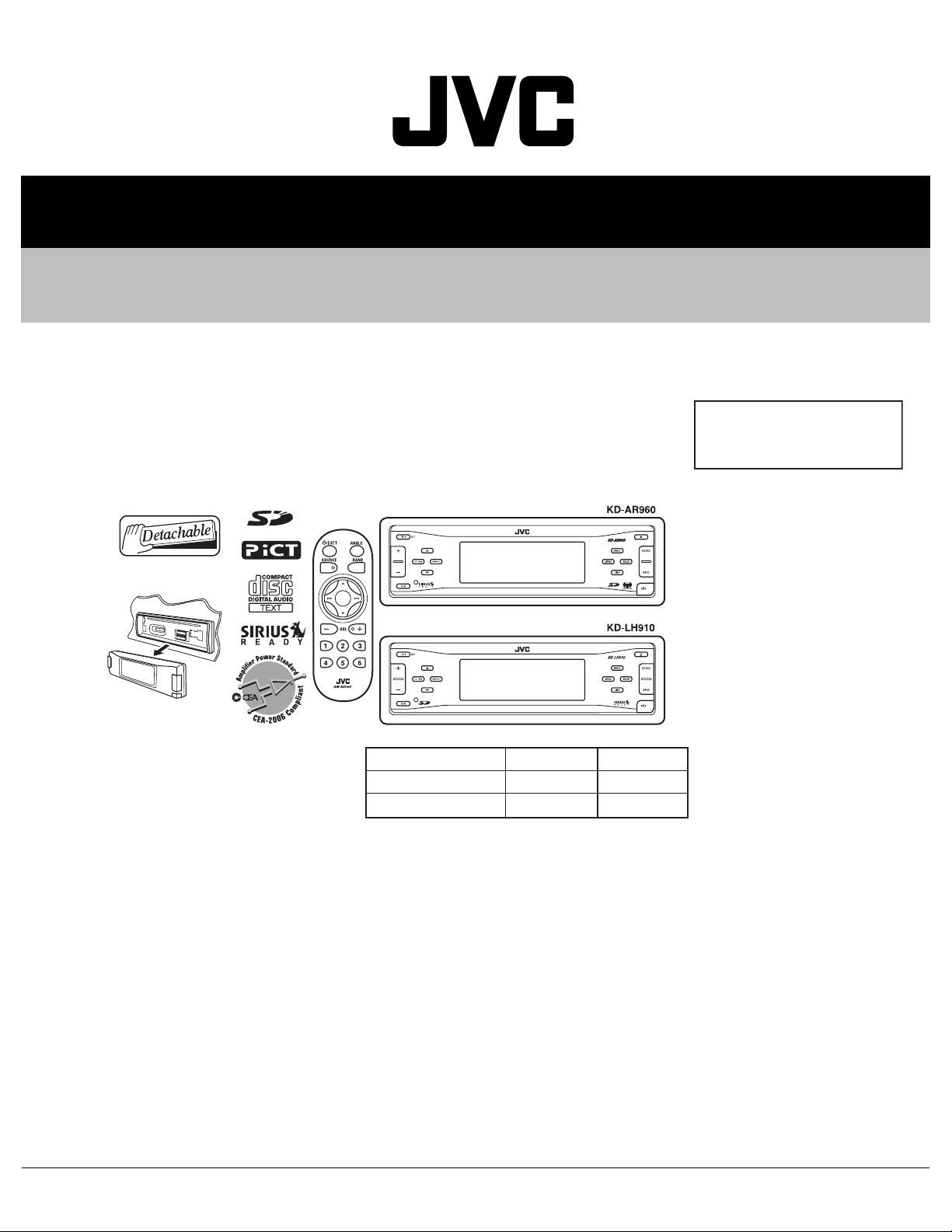
SERVICE MANUAL
CD/SD RECEIVER
MA14220052
KD-AR960,KD-LH910
Area suffix
J --------------- Northern America
KD-AR960 KD-LH910
ARSENAL rogo
LINE IN
٤
٤
TABLE OF CONTENTS
1 PRECAUTIONS . . . . . . . . . . . . . . . . . . . . . . . . . . . . . . . . . . . . . . . . . . . . . . . . . . . . . . . . . . . . . . . . . . . . . . . 1-3
2 SPECIFIC SERVICE INSTRUCTIONS . . . . . . . . . . . . . . . . . . . . . . . . . . . . . . . . . . . . . . . . . . . . . . . . . . . . . . 1-5
3 DISASSEMBLY . . . . . . . . . . . . . . . . . . . . . . . . . . . . . . . . . . . . . . . . . . . . . . . . . . . . . . . . . . . . . . . . . . . . . . . 1-6
4 ADJUSTMENT . . . . . . . . . . . . . . . . . . . . . . . . . . . . . . . . . . . . . . . . . . . . . . . . . . . . . . . . . . . . . . . . . . . . . . . 1-22
5 TROUBLESHOOTING . . . . . . . . . . . . . . . . . . . . . . . . . . . . . . . . . . . . . . . . . . . . . . . . . . . . . . . . . . . . . . . . . 1-26
COPYRIGHT © 2005 Victor Company of Japan, Limited
No.MA142
2005/2
Page 2
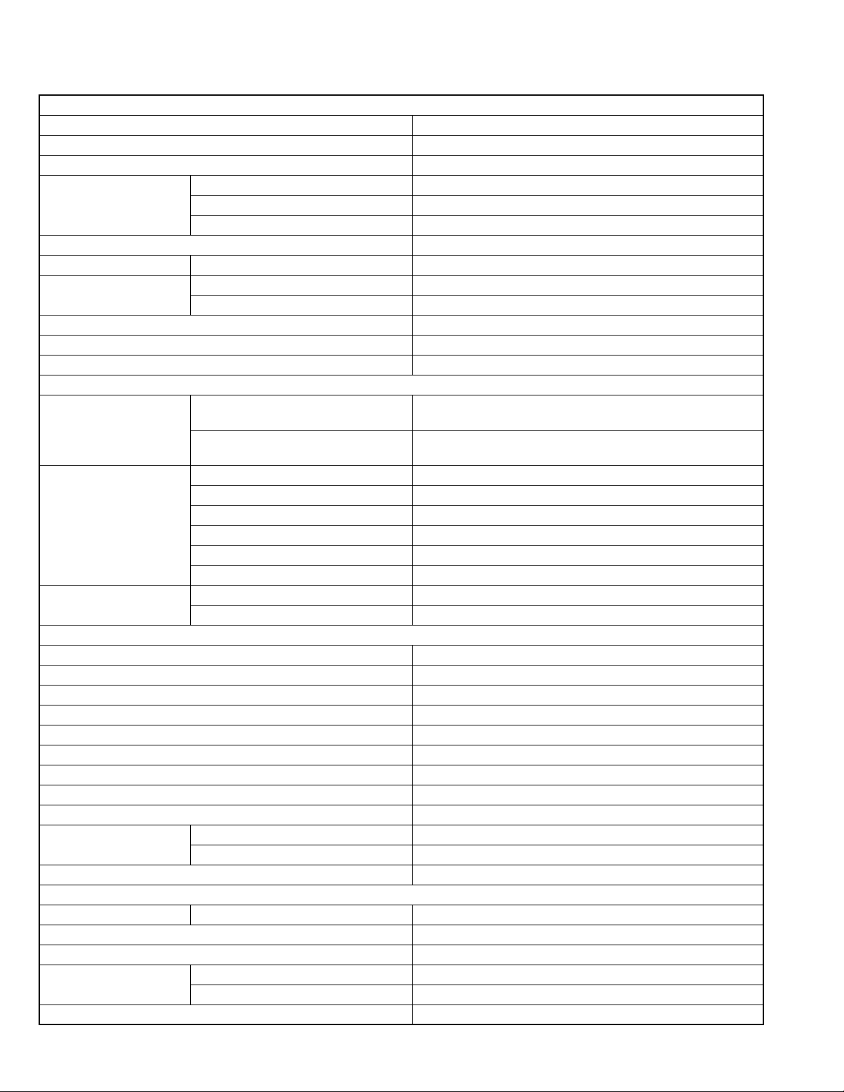
SPECIFICATION
AUDIO AMPLIFIER SECTION
Power Output 20 W RMS × 4 Channels at 4 Ω and
Signal to Noise Ratio 80 dBA (reference: 1 W into 4 Ω)
Load Impedance 4 Ω (4 Ω to 8 Ω allowance)
Equalizer Control Range Low ±12 dB (60 Hz, 80 Hz, 100 Hz, 120 Hz)
Mid ±12 dB (Fix)
High ±12 dB (8 kHz, 10 kHz, 12 kHz, 15 kHz)
Frequency Response 40 Hz to 20 000 Hz
Line-In Level/Impedance KD-AR960 1.5 V/20 kΩ load
Line-Out Level/Impedance KD-AR960 5.0 V/20 kΩ load (full scale)
KD-LH910 4.0 V/20 kΩ load (full scale)
Output Impedance 1 kΩ
Subwoofer-Out Level/Impedance 2.0 V/20 kΩ load (full scale)
Other Terminals CD changer, LINE IN (for KD-AR960)
TUNER SECTION
Frequency Range FM 87.5 MHz to 107.9 MHz (with channel interval set to 200 kHz)
87.5 MHz to 108.0 MHz (with channel interval set to 50 kHz)
AM 530 kHz to 1 710 kHz (with channel interval set to 10 kHz)
531 kHz to 1 602 kHz (with channel interval set to 9 kHz)
FM Tuner Usable Sensitivity 11.3 dBf (1.0 µV/75 Ω)
50 dB Quieting Sensitivity 16.3 dBf (1.8 µV/75 Ω)
Alternate Channel Selectivity (400 kHz) 65 dB
Frequency Response 40 Hz to 15 000 Hz
Stereo Separation 35 dB
Capture Ratio 1.5 dB
AM Tuner Sensitivity 20 µV
Selectivity 35 dB
CD/SD PLAYER SECTION
Type Compact disc player
Signal Detection System Non-contact optical pickup (semiconductor laser)
Number of Channels 2 channels (stereo)
Frequency Response 5 Hz to 20 000 Hz
Dynamic Range 96 dB
Signal-to-Noise Ratio 98 dB
Wow and Flutter Less than measurable limit
MP3 (MPEG1/2 Audio Layer 3) Max. Bit Rate: 320 kbps
WMA (Windows Media Audio) Max. Bit Rate: 192 kbps
Playable SD Card Format Fat 12/16
Storage Up to 512 MB
Playable Audio Format for SD Card MP3/WMA
GENERAL
Power Requirement Operating Voltage DC 14.4 V (11 V to 16 V allowance)
Grounding System Negative ground
Allowable Operating Temperature 0°C to +40°C (32°F to 104°F)
Dimensions (W × H × D) Installation Size (approx.) 182 mm × 52 mm × 159 mm (7-3/16" × 2-1/16" × 6-5/16")
Panel Size (approx.) 188 mm × 58 mm × 12 mm (7-7/16" × 2-5/16" × 1/2")
Mass (approx.) 1.7 kg (3.8 lbs) (excluding accessories)
[< or =] 1% THD+N
Design and specifications are subject to change without notice.
1-2 (No.MA142)
Page 3
1.1 Safety Precautions
SECTION 1
PRECAUTIONS
!
!
Burrs formed during molding may be left over on some parts of the chassis. Therefore,
pay attention to such burrs in the case of preforming repair of this system.
Please use enough caution not to see the beam directly or touch it in case of an
adjustment or operation check.
(No.MA142)1-3
Page 4
1.2 Preventing static electricity
Electrostatic discharge (ESD), which occurs when static electricity stored in the body, fabric, etc. is discharged, can destroy the laser
diode in the traverse unit (optical pickup). Take care to prevent this when performing repairs.
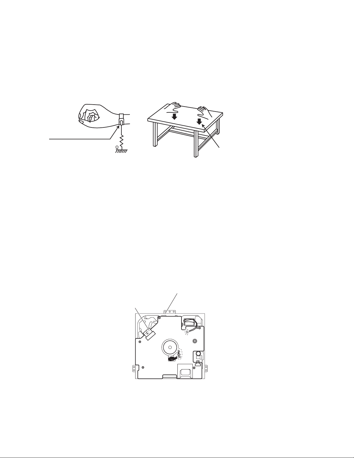
1.2.1 Grounding to prevent damage by static electricity
Static electricity in the work area can destroy the optical pickup (laser diode) in devices such as CD players.
Be careful to use proper grounding in the area where repairs are being performed.
(1) Ground the workbench
Ground the workbench by laying conductive material (such as a conductive sheet) or an iron plate over it before placing the
traverse unit (optical pickup) on it.
(2) Ground yourself
Use an anti-static wrist strap to release any static electricity built up in your body.
(caption)
Anti-static wrist strap
1M
Conductive material
(conductive sheet) or iron plate
(3) Handling the optical pickup
• In order to maintain quality during transport and before installation, both sides of the laser diode on the replacement optical
pickup are shorted. After replacement, return the shorted parts to their original condition.
(Refer to the text.)
• Do not use a tester to check the condition of the laser diode in the optical pickup. The tester's internal power source can easily
destroy the laser diode.
1.3 Handling the traverse unit (optical pickup)
(1) Do not subject the traverse unit (optical pickup) to strong shocks, as it is a sensitive, complex unit.
(2) Cut off the shorted part of the flexible cable using nippers, etc. after replacing the optical pickup. For specific details, refer to the
replacement procedure in the text. Remove the anti-static pin when replacing the traverse unit. Be careful not to take too long a
time when attaching it to the connector.
(3) Handle the flexible cable carefully as it may break when subjected to strong force.
(4) It is not possible to adjust the semi-fixed resistor that adjusts the laser power. Do not turn it.
1.4 Attention when traverse unit is decomposed
*Please refer to "Disassembly method" in the text for the CD pickup unit.
• Apply solder to the short land before the flexible wire is disconnected from the connector on the CD pickup unit.
(If the flexible wire is disconnected without applying solder, the CD pickup may be destroyed by static electricity.)
• In the assembly, be sure to remove solder from the short land after connecting the flexible wire.
CD mechanism assembly
Flexible wire
1-4 (No.MA142)
Page 5

SECTION 2
SPECIFIC SERVICE INSTRUCTIONS
This service manual does not describe SPECIFIC SERVICE INSTRUCTIONS.
(No.MA142)1-5
Page 6
SECTION 3
DISASSEMBLY
3.1 Main body section
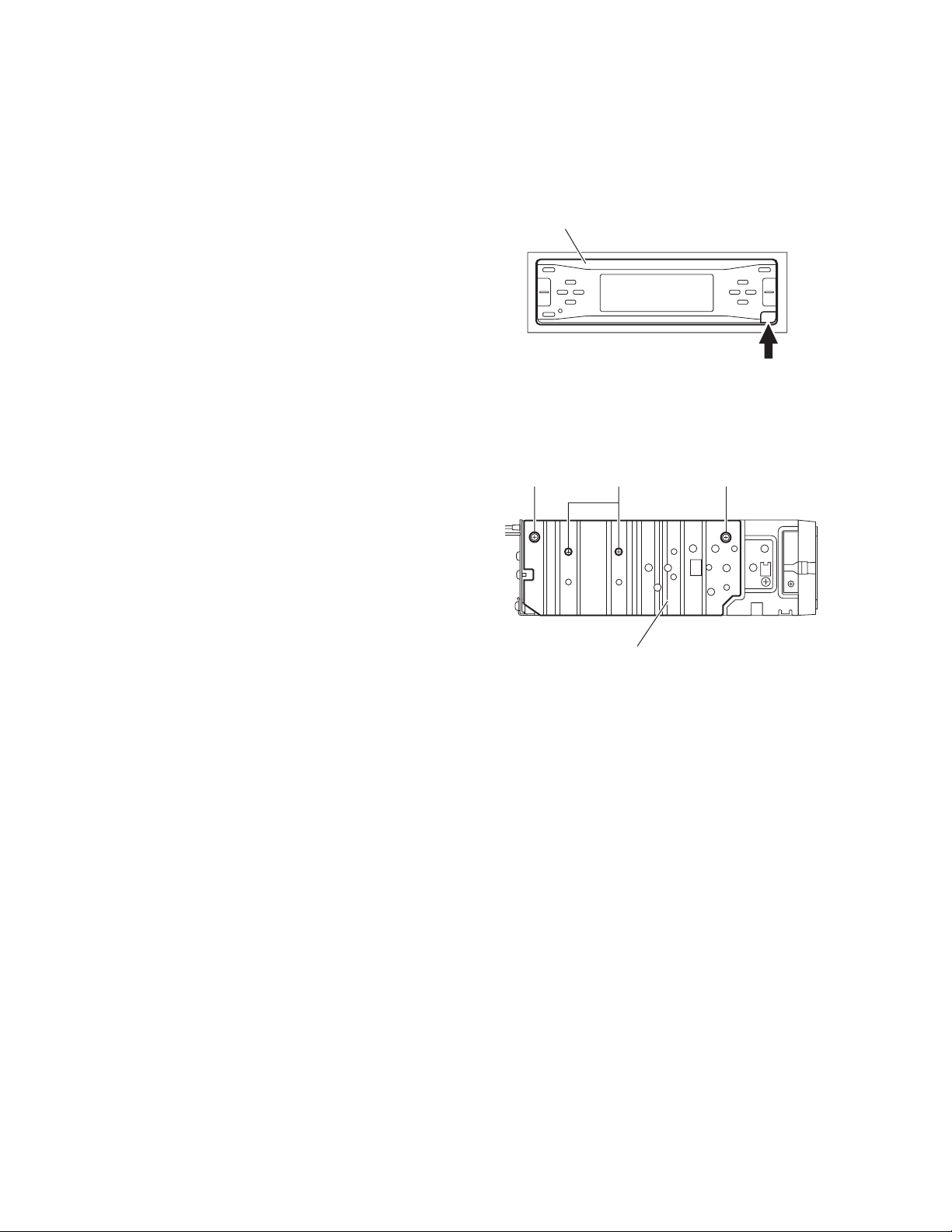
3.1.1 Removing the front panel assembly
(See Fig.1)
(1) Push the detach button in the lower right part of the front
panel assembly.
(2) Take out the front panel assembly.
3.1.2 Removing the heat sink
(See Fig.2)
(1) From the left side of the main body, remove the two screws
A and two screws B attaching the heat sink.
(2) Take out the heat sink.
Front panel assembly
Detach button
Fig.1
AAB
Heat sink
Fig.2
1-6 (No.MA142)
Page 7
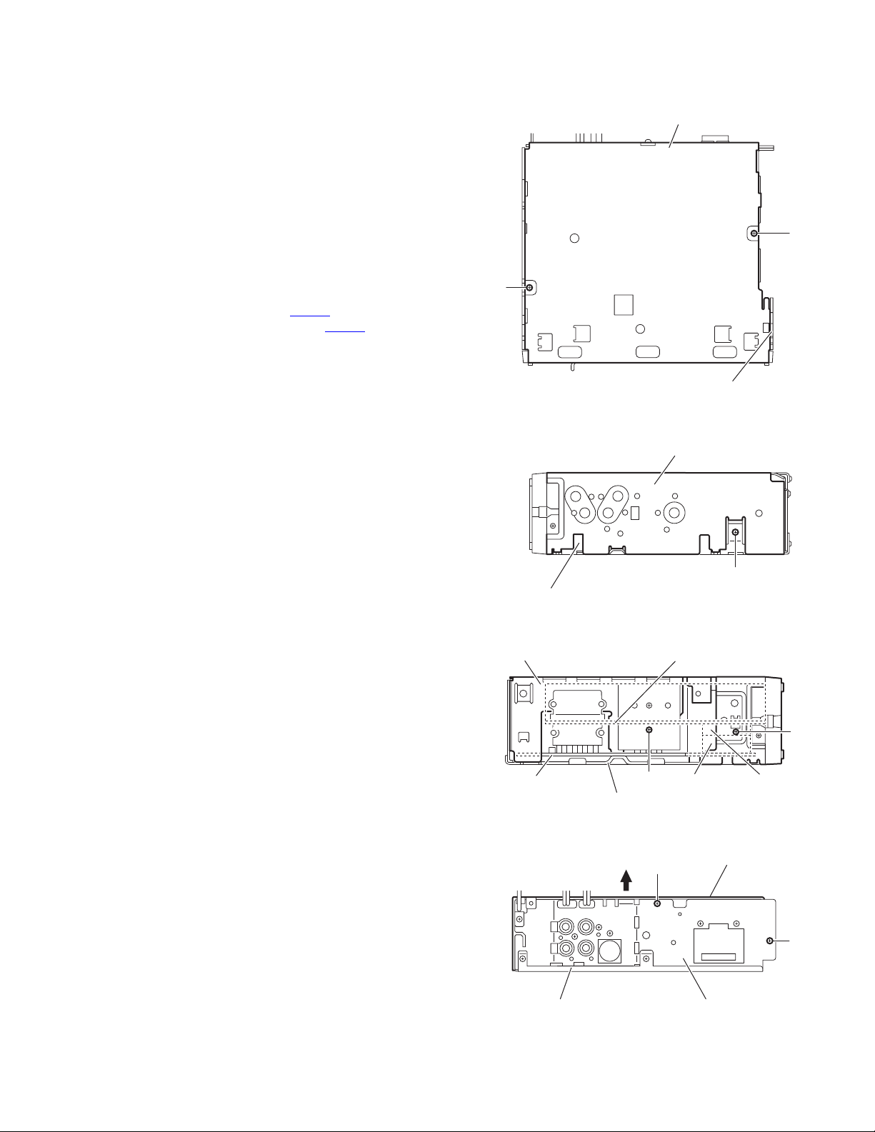
3.1.3 Removing the top chassis assembly
(See Figs.3 to 6)
• Prior to performing the following procedures, remove the heat
sink.
Reference:
Remove the front panel assembly as required.
(1) From the bottom side of the main body, remove the two
screws C attaching the top chassis assembly to the bottom
chassis assembly. (See Fig.3)
(2) From the both and back sides of the main body, remove the
four screws D attaching the top chassis assembly to the
bottom chassis assembly. (See Figs.4 to 6)
(3) From the left side of the main body, remove the screw E at-
taching the top chassis assembly. (See Fig.5)
(4) Lift the top chassis assembly in the direction of the arrow,
and disconnect the connector CN501
nism assembly from the connector CN702
board. (See Figs.5 and 6)
(5) Take out the top chassis assembly from the bottom chassis
assembly.
on the CD mecha-
on the main
Bottom chassis assembly
C
C
Top chassis assembly
Fig.3
Top chassis assembly
Bottom chassis assembly
Top chassis assembly
Main board
Bottom chassis assembly
D
Fig.4
CD mechanism assembly
CN702
E
Fig.5
Top chassis assembly
D
CN501
D
D
Bottom chassis assembly
Rear bracket
Fig.6
(No.MA142)1-7
Page 8
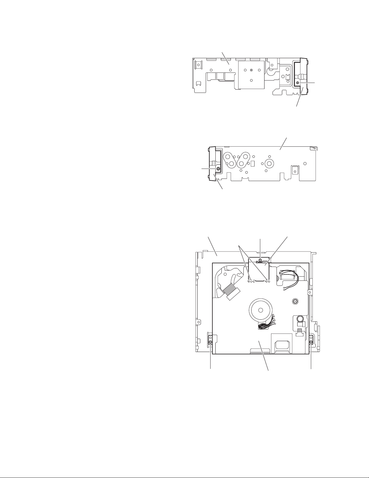
3.1.4 Removing the front chassis
(See Figs.7 and 8)
• Prior to performing the following procedure, remove the front
panel assembly, heat sink and top chassis assembly.
(1) From the both sides of the top chassis assembly, remove
the two screws F attaching the front chassis. (See Figs.7
and 8)
(2) Take out the front chassis forward.
3.1.5 Removing the CD mechanism assembly
(See Fig.9)
• Prior to performing the following procedures, remove the front
panel assembly, heat sink and top chassis assembly.
Reference:
Remove the front chassis as required.
(1) From the inside of the top chassis assembly, remove the
three screws G attaching the CD mechanism assembly.
Reference:
When attaching the screw G, attach it with the mecha
heat sink.
(2) Remove the mecha heat sink from the CD mechanism as-
sembly, and take out the CD mechanism assembly from
the top chassis.
Reference:
When attaching the mecha heat sink, pass the craws of it
through the slots a of CD mechanism assembly.
Top chassis assembly
F
Front chassis
Top chassis
Slots a
Front chassis
Fig.7
Top chassis assembly
Fig.8
Mecha heat sink
G
F
1-8 (No.MA142)
G GCD mechanism assembly
Fig.9
Page 9
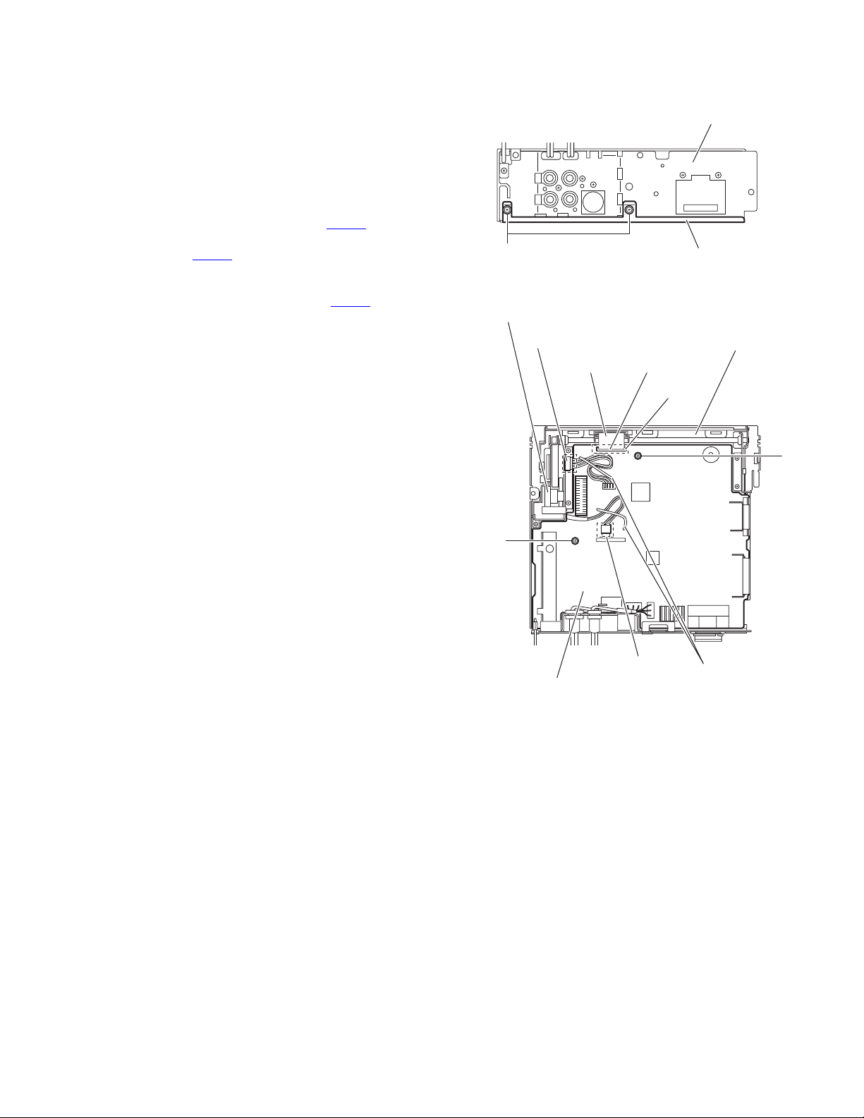
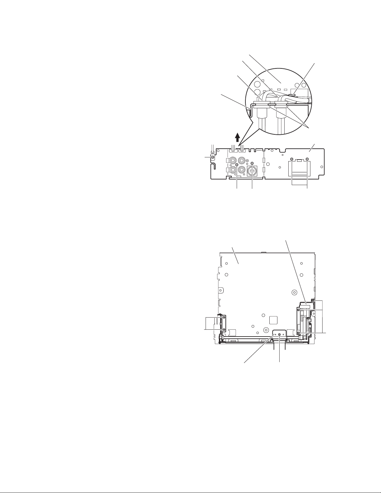
3.1.6 Removing the main board
(See Figs.10 and 11)
• Prior to performing the following procedures, remove the front
panel assembly, heat sink and top chassis assembly.
(1) From the back side of the bottom chassis assembly, re-
move the two screws H attaching the rear bracket to the
bottom chassis assembly. (See Fig.10)
(2) From the top side of the bottom chassis assembly, remove
the two screws J attaching the main board to the bottom
chassis assembly. (See Fig.11)
(3) Release the stopper of the connector CN701
board in an upward direction, disconnect the card wire from
the connector CN701
(4) Disconnect the wire from the connector of the front door
mechanism assembly. (See Fig.11)
(5) Disconnect the wire from the connector CN951
board. (See Fig.11)
Reference:
After connecting the wires, fix the wires with the wire
clamp.
(6) Take out the main board with the rear bracket from the bot-
tom chassis assembly.
. (See Fig.11)
on the main
on the main
H
Front door mechanism assembly
Connector
Card wire
Bottom chassis assembly
Fig.10
Bottom chassis assembly
CN701
Stopper
Rear bracket
J
J
Main board
CN951
Fig.11
Wire clamps
(No.MA142)1-9
Page 10
3.1.7 Removing the rear bracket
(See Fig.12)
• Prior to performing the following procedures, remove the front
panel assembly, heat sink, top chassis assembly and main
board.
(1) From the back side of the main board, remove the wires
from the rear bracket in the direction of the arrow.
(2) Remove the screw K, three screws L and screw M attach-
ing the rear bracket to the main board.
Reference:
After attaching the rear bracket to the main board, pass
the wires through the wire holder and insert them into the
slots of the rear bracket.
(3) Take out the rear bracket from the main board.
Wire
Wire (KD-AR960)
Rear bracket
M
Main board
Wire holder
Slots
Rear bracket
3.1.8 Removing the front door mechanism assembly
(See Fig.13)
• Prior to performing the following procedures, remove the front
panel assembly, heat sink, top chassis assembly and main
board.
(1) From the top side of the bottom chassis assembly, remove
the screw N attaching the FPC guide to the bottom chassis.
(2) Remove the five screws P attaching the front door mecha-
nism assembly to the bottom chassis.
Reference:
When attaching the screws N and P, apply a locking
agent them.
(3) Take out the front door mechanism assembly from the bot-
tom chassis.
Bottom chassis
P
L K
Front door mechanism assembly
FPC guide
L
Fig.12
P
N
1-10 (No.MA142)
Fig.13
Page 11
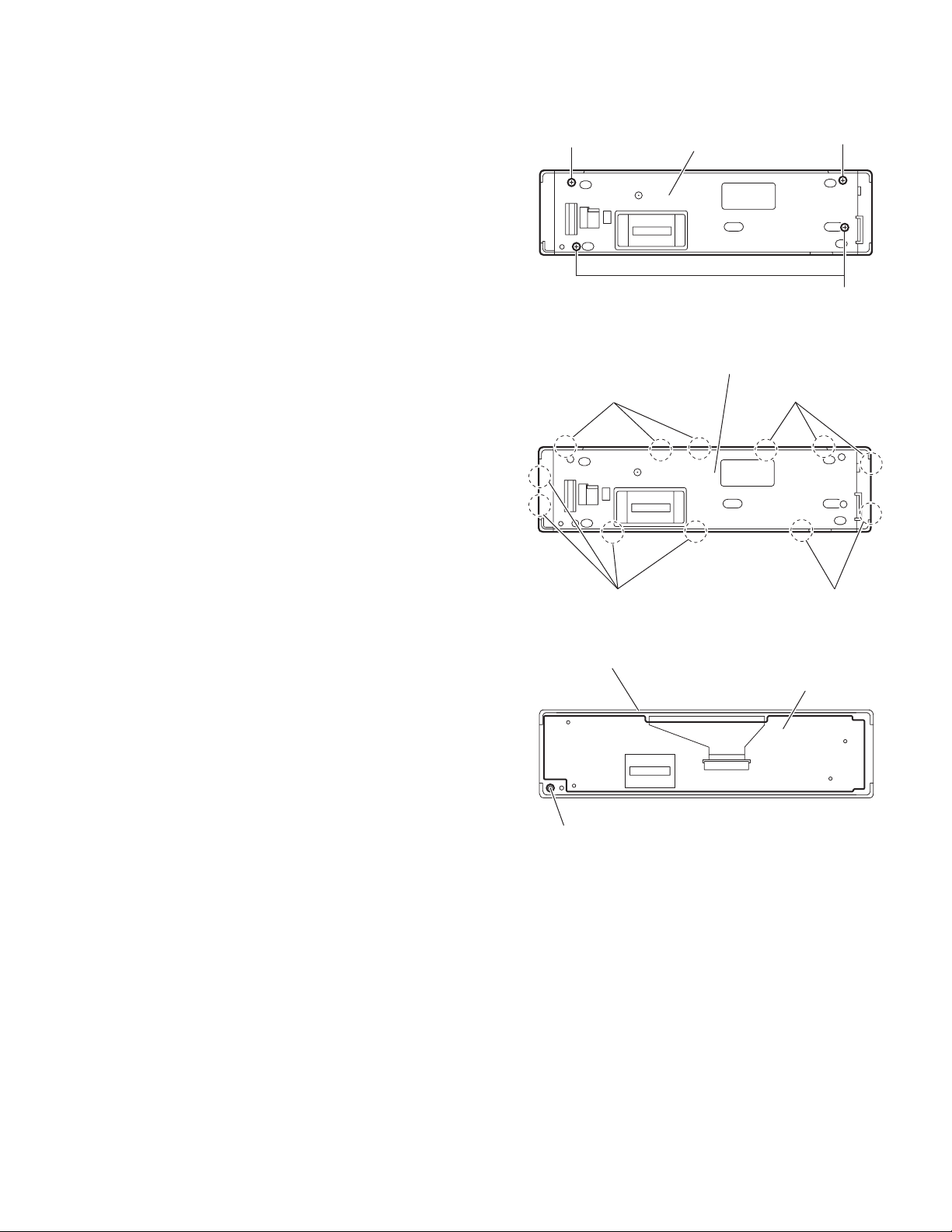
3.1.9 Removing the switch board
(See Figs.14 to 16)
• Prior to performing the following procedures, remove the front
panel assembly.
(1) From the back side of the front panel assembly, remove the
four screws Q attaching the rear cover assembly to the
front panel assembly. (See Fig.14)
(2) Release the twelve joints b of the front panel assembly and
remove the rear cover assembly. (See Fig.15)
(3) Take out the switch board from the front panel assembly.
(See Fig.16)
Note:
When removing the rear cover assembly and switch board, be
careful not to lose the comp. spring. (See Fig.16)
Q
Joints b Joints b
Rear cover
Fig.14
Rear cover assembly
Q
Q
Joints b
Front panel assembly
Comp. spring
Joints b
Fig.15
Switch board
Fig.16
(No.MA142)1-11
Page 12
3.2 CD mechanism assembly section
• Remove the CD mechanism assembly from the main body.
(See "3.1.5 Removing the CD mechanism assembly".)
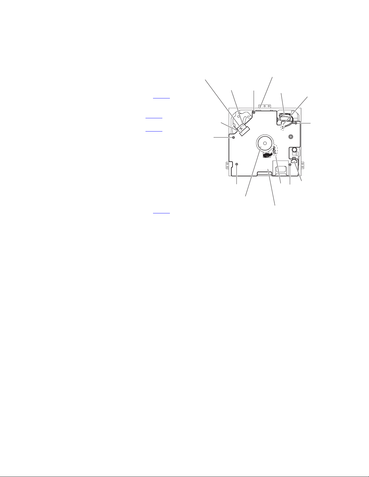
3.2.1 Removing the mechanism control board
(See Fig.1)
(1) From the bottom side of the CD mechanism assembly, sol-
der the short sections on the flexible wire.
Caution:
Solder the short sections on the flexible wire before disconnecting the flexible wire from the connector CN601
on the mechanism control board. If you do not follow this
instruction, the CD pickup may be damaged.
(2) Disconnect the flexible wire from the connector CN601
the mechanism control board.
(3) Disconnect the flexible wire from the connector CN602
the mechanism control board.
(4) Remove the solders from the soldered sections a on the
mechanism control board and remove the wires of the feed
motor.
(5) Remove the solders from the soldered sections b on the
mechanism control board, and remove each wire of the
spindle motor and other parts.
(6) Remove the five screws A attaching the mechanism con-
trol board.
Caution:
When reassembling, remove the solders from the short sections after connecting the flexible wire to the connector CN601
on the mechanism control board.
on
on
Short sections
Flexible wire
CN601
A
CD mechanism assembly
A
A
Spindle motor
Mechanism control board
Fig.1
Feed motor
b
A
a
A
CN602
1-12 (No.MA142)
Page 13

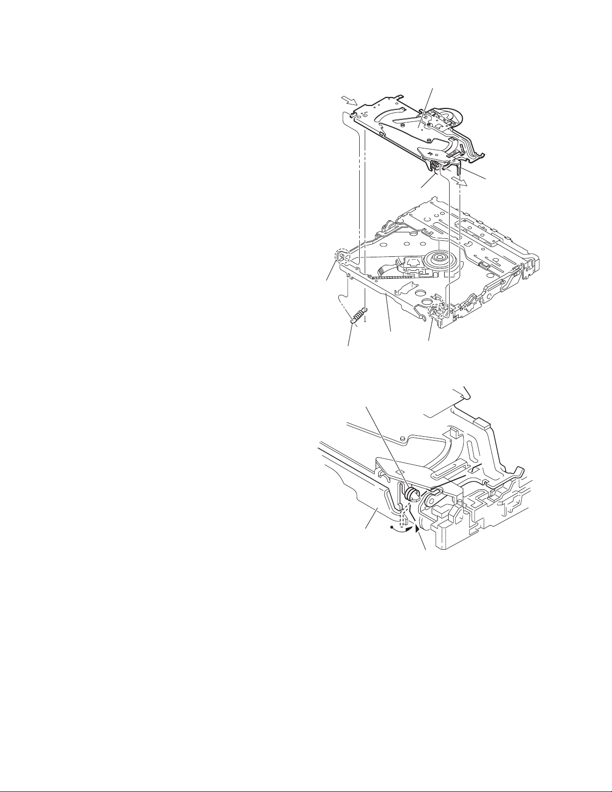
3.2.2 Removing the top cover
r
(See Fig.2)
(1) From the back side of the CD mechanism assembly, re-
move the two screws B attaching the top cover.
(2) Take out the top cover in an upward direction.
Reference:
When attaching the top cover, set the sections c of the top cover under the bending sections d of the chassis base.
3.2.3 Removing the mechanism section
(See Figs.2 to 4)
• Remove the mechanism control board and top cover.
(1) From the front side of the CD mechanism assembly, re-
move the two screws C attaching the right and left stoppers. (See Fig.2)
(2) Remove the two floating springs on the bottom side of the
CD mechanism assembly. (See Fig.3)
(3) Take out the mechanism section in an upward direction
and remove the three damper springs from the dampers.
(See Fig.4)
Caution:
• When reassembling the mechanism section, reattach the
damper springs to the dampers respectively and insert the
three shafts on the bottom of the mechanism section to the
dampers. (See Fig.4)
• Before inserting the shaft to the dampers, apply IPA to the
hole of damper.
Floating spring
Fig.3
Mechanism section
C
Stopper
Top cover
Stopper
C
Fig.2
B
d
c
Chassis base
B
Damper
spring(F)
(Green)
Damper
(Black)
Damper
spring(F)
(Green)
Damper
spring(R)
(Red)
Dampe
(Yellow)
Damper
(Black)
Fig.4
(No.MA142)1-13
Page 14
3.2.4 Removing the clamper unit
(See Figs.5 and 6)
• Remove the mechanism control board, top cover and mecha-
nism section.
(1) From the bottom side of the mechanism section, remove
the clamper 2 spring. (See Fig.5)
(2) Release section e of the clamper spring from the bending
section of the chassis base. (See Fig.6)
(3) Move the clamper unit in the direction of the arrow and re-
lease the joints (f, g). (See Fig.5)
(4) Take out the clamper unit in an upward direction. (See
Fig.5)
3.2.5 Reattaching the clamper unit
(See Figs.5 to 9)
(1) From the bottom side of the mechanism section, attach the
clamper spring to the clamper unit. (See Figs.5 and 9)
(2) Move the clamper unit to set the joints (f, g) to each projec-
tion of the chassis base. (See Fig.5)
(3) Make sure that section h of the clamper unit is inserted to
the notch of the chassis base. (See Figs.5 and 8)
(4) Move the clamper spring to the outside of the bending part
of the chassis base. (See Fig.6)
Caution:
When reattaching the clamper unit, temporarily hook the
end of the clamper spring as shown in the figure to make
the work easy. (See Fig.9.)
(5) Attach the clamper 2 spring to the chassis base and
clamper unit. (See Figs.5 and 7.)
Clamper spring
f
Chassis base
Clamper 2 spring
Clamper unit
h
g
Fig.5
Clamper spring
Chassis base
e
Fig.6
1-14 (No.MA142)
Page 15

Clamper 2 spring
Clamper unit
Chassis base
Clamper unit
Fig.7
Clamper spring
Fig.9
Clamper unit
Notch
h
Fig.8
(No.MA142)1-15
Page 16

3.2.6 Removing the front unit
(See Figs10 to 12)
• Remove the mechanism control board, top cover and mecha-
nism section.
(1) From the bottom side of the mechanism section, remove
the double-stick tape fixing the flexible wire. (See Fig.10.)
(2) From the top side of the mechanism section, remove the
screw D attaching the front unit. (See Figs.11 and 12.)
(3) Move the front unit toward the front to release the joint i.
(See Figs.11 and 12.)
(4) Release two joints j and k on the right side of the chassis
base. (See Fig.12)
(5) Take out the front unit in an upward direction.
(6) Remove the double-stick tape fixing the flexible wire and
remove the two screws E attaching the switch wire. (See
Fig.12)
Reference:
You can remove the switch wire only without removing the
front unit.
Flexible wire
Double-stick
tape
Fig.10
Double-stick tape
Flexible
wire
Front unit
E
D
i
Fig.11
Switch wire
D
Front unit
1-16 (No.MA142)
j
k
Chassis base
i
Fig.12
Page 17

3.2.7 Removing the loading arm assembly
(See Figs.13 and 14)
• Remove the mechanism control board, top cover, mechanism
section and front unit.
(1) From top side of the mechanism section, move the loading
arm assembly in the direction of the arrow. (See Fig.13)
(2) Release the projections from the right and left joints (m, n)
of the chassis base. (See Figs.13 and 14)
(3) Release the projection from notch p of the connect arm on
the right side of the mechanism section and release the
projection from notch q of the slide cam assembly on the
left side. (See Figs.13 and 14.)
Loading arm assembly
n
Chassis base
p
m
Fig.13
Loading arm assembly
Side cam
assembly
q
n
Chassis base
Fig.14
m
p
Connect arm
(No.MA142)1-17
Page 18

3.2.8 Removing the rod (L), rod (R) and roller assembly
(See Figs.15 and 16)
• Remove the mechanism control board, top cover, mechanism
section, front unit and loading arm assembly.
(1) From the bottom side of the loading arm assembly, release
the rod (L) and (R) from the joints r. (See Fig.15)
(2) Remove the roller assembly from the loading arm assem-
bly. (See Fig.16)
(3) Remove the two collars and washer from the roller assem-
bly. (See Fig.16)
Caution:
After attaching the roller assembly to the loading arm assembly, attach the rod (L) and (R). Then attach the rods to the right
and left collars of the roller assembly. (See Fig.15)
Collar
Rod(R) Rod(L)
r
Rod(R)
Roller assembly
Loading arm assembly
r
Collar
Rod(L)
r
r
Fig.15
Rod(L)
Collar
Washer
Roller assembly
Rod(R)
Collar
Loading arm assembly
Fig.16
1-18 (No.MA142)
Page 19

3.2.9 Removing the CD pickup
(See Figs.17 to 19)
• Remove the mechanism control board.
(1) From the bottom side of the CD mechanism assembly, turn
the feed gear in the direction of the arrow to move the CD
pickup assembly outwards. (See Fig.17)
(2) Remove the screw F and remove the thrust spring. (See
Fig.17)
(3) Remove the CD pickup assembly in an upward direction
from the side of L.S. gear and release the CD pickup assembly from joint s of the sub guide. (See Fig.18)
(4) Move the lead screw of the CD pickup assembly in the di-
rection of the arrow to release at joint t. (See Fig.18)
(5) Remove the screw G attaching the rack spring and rack
plate on the CD pickup assembly. (See Fig.19)
(6) Pull out the lead screw. (See Fig.19)
Caution:
• When attaching the CD pickup assembly, attach the CD
pickup assembly at joint s of sub guide first, and attach the
lead screw to the joint t on the L.S.holder 2. (See Fig.18)
• Perform electric adjustment after replacing the pickup.
CD mechanism assembly
CD pickup assembly
Thrust spring
Feed gear
F
Fig.17
L.S.holder 2
Sub guide
s
Rack spring
Rack plate
t
Lead screw
Fig.18
G
CD Pickup assembly
L.S. Gear
Lead screw
CD Pickup
Fig.19
(No.MA142)1-19
Page 20

3.2.10 Removing the spindle motor
r
r
(See Fig.20)
• Remove the mechanism control board, top cover, mechanism
section and clamper unit.
(1) From the top side of the mechanism section, remove the
T.table assembly and washer from the spindle motor.
(2) Remove the two screws H attaching the spindle motor.
(3) Take out the spindle motor from the bottom side of the
mechanism section.
Caution:
Perform adjustment when reattaching the spindle motor.
3.2.11 Removing the feed motor
(See Figs.21 and 22)
• Remove the mechanism control board.
(1) From the bottom side of the CD mechanism assembly, re-
move the F.T.spring. (See Fig.21)
(2) Remove the two screws J attaching the feed motor assem-
bly. (See Fig.21)
(3) Remove the slit washer from the motor H.assembly and
pull out the worm wheel. (See Fig.22)
(4) Remove the two screws K attaching the feed motor. (See
Fig.22)
T. table assembly
F.T.Spring
Washer
H
Spindle moto
Fig.20
J
Feed motor assembly
1-20 (No.MA142)
Fig.21
Slit washer
Worm wheel
Feed moto
K
Motor H.assembly
Fig.22
Page 21

3.2.12 Removing the SW board and rest SW board
(See Fig.23)
• Remove the mechanism control board.
(1) From the bottom side of the CD mechanism assembly, re-
move the screw L attaching the SW board.
(2) Remove the screw M attaching the rest SW board.
CD mechanism assembly
ML
SW boardRest SW board
Fig.23
(No.MA142)1-21
Page 22

SECTION 4
ADJUSTMENT
4.1 Adjustment method
Test instruments required for adjustment
(1) Digital oscilloscope (100MHz)
(2) Electric voltmeter
(3) Digital tester
(4) Tracking offset meter
(5) Test Disc JVC :CTS-1000
(6) Extension cable for check
EXTGS004-26P × 1
Standard volume position
Balance and Bass &Treble volume : lndication"0"
Loudness : OFF
How to connect the extension cable for adjusting
Caution:
Be sure to attach the heat sink and rear bracket onto the power amplifier IC and regulator IC respectively, before supply the power.
If voltage is applied without attaching these parts, the power amplifier IC and regulator IC will be destroyed by heat.
Standard measuring conditions
Power supply voltage DC14.4V(11 to 16V)
Load impedance 20KΩ(2 Speakers connection)
Output Level KD-AR960 Line out 5.0V (Vol. MAX)
KD-LH910 Line out 4.0V (Vol. MAX)
Dummy load
Exclusive dummy load should be used for AM,and FM. For FM
dummy load,there is a loss of 6dB between SSG output and
antenna input.The loss of 6dB need not be considered since
direct reading of figures are applied in this working standard.
Extension cable: EXTGS004-26P
CN702
Heat sink
Rear bracket
1-22 (No.MA142)
Page 23

4.2 Service mode
4.2.1 Service mode setting
(1) Push POWER BOTTON (Power ON)
(2) Set to service mode
By pushing and holding "DISP" button and "VOLUME +" button sequentially.
(3) Select the menu with "CURSOR" button, and decide it with "OK" button.
(4) When the "BACK" button is pushed, it returns to the former menu.
"VOLUME +" button
"OK" button "DISP" button
"CURSOR" button
Service Mode (MENU)
Service Mode
Running Mode
Data Clear
RDS Service Mode
Service Mode
VERSION
ERROR READ
CD DATA READ
"BACK" button
Version
MAIN
CD V
CH V
V
Error Read
ERROR READ
OK:Function
CD Error Read
CD Error Read
E1 E3
E2
1 4
2 5
3
CH Error Read
CH Error Read
E1 E3
E2
1 4
2 5
3
Panel Mecha Error Read
Panel Mecha Error Read
E1 E3
E2
1 4
2 5
AB
3
(No.MA142)1-23
Page 24

AB
f
f
CD Data Read
CD Data Read
OK:Read
Running Mode
RUNNING PANEL MECHA 2
RUNNING PANEL MECHA 3
RUNNING CD
ADJ NOW
FEB FEO TEB RFG
FGA TEO TGA
ADJ INT
FEB FEO TEB RFG
FGA TEO TGA
OTHERS
IOP TEMP IOP INT
TEMP MIX P TOTAL H
Running Panel Mecha 2
RUNNING PANEL MECHA 2
COUNT :
ERROR :
Running Panel Mecha 3
RUNNING PANEL MECHA 3
COUNT :
ERROR :
ADJ NOW
The auto adjustment value o
survo at now
ADJ INT
The auto adjustment value o
survo at initial
Data Clear
EPROM Clear
Name Clear
CD Error Clear
CH Error Clear
Panel Mecha Error Clear
Picture Clear
Running CD
RUNNING CD
COUNT :
ERROR :
EPROM Clear
NOW
EPROM CLEAR
Name Clear
NOW
NAME CLEAR
C D
1-24 (No.MA142)
Page 25

C
D
CD Error Clear
NOW
CD ERROR CLEAR
CH Error Clear
NOW
CH ERROR CLEAR
Panel Mecha Error Clear
NOW
PANEL MECHA ERROR CLEAR
Picture Clear
NOW
PICTURE CLEAR
RDS Service Mode
VER=
SPI =
PTY=
AF
PS =
PTY= CLOCK=00:00
Freq=87.5MHz
PI =
SM=
SQ=
ONLY USED WITH RDS MODEL
TP/TA=
MS/DI=
(No.MA142)1-25
Page 26

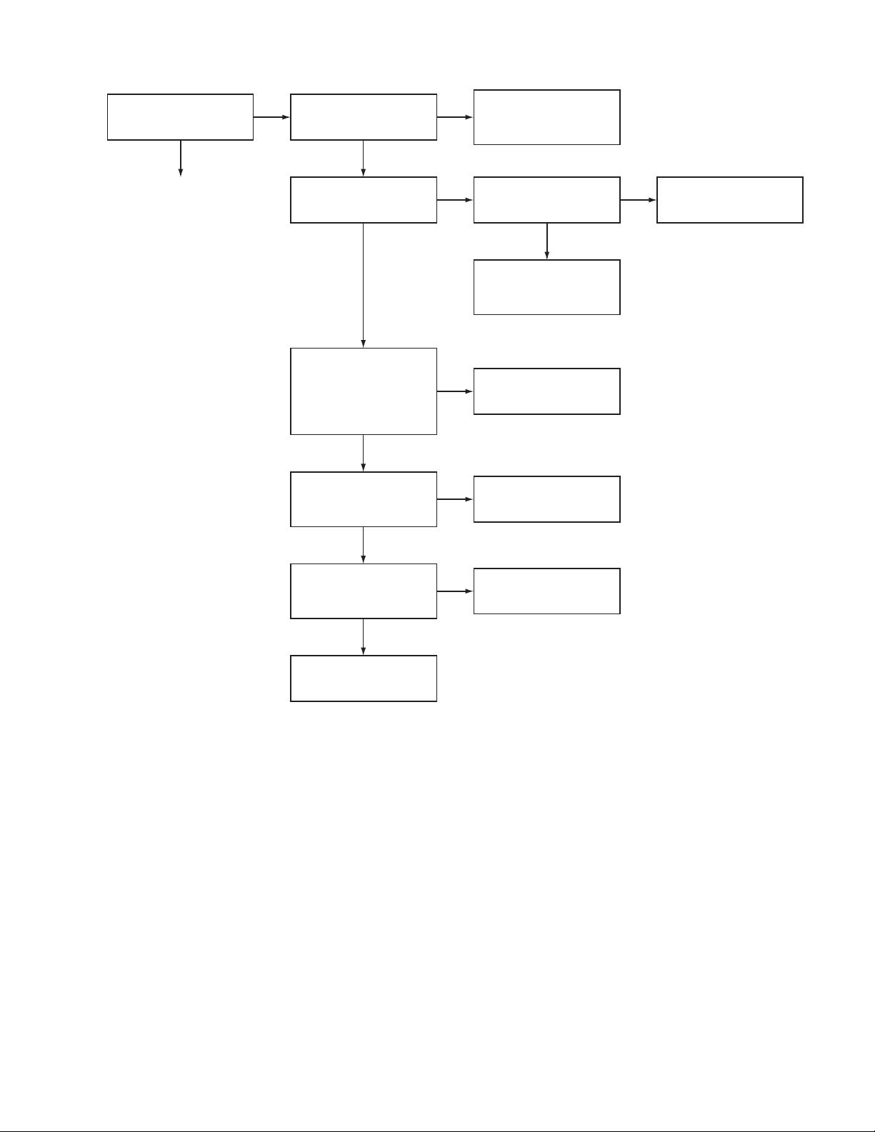
5.1 Feed section
SECTION 5
TROUBLESHOOTING
Is 5V or 0V at IC601
pin 63?
YES
Is 4V present at both
sides of the feed motor?
YES
Check the feed motor.
5.2 Focus section
5.3 Spindle section
NO
Is the wiring for IC601
pin 63 correct?
NO
Is 6V or 2V present at
IC681 pins 26 and 27?
Check IC681.
When the lens is
moving:
Does the S-search
waveform appear at
IC681 pins 10 and 11?
NO
NO
YES
4V
YES
YES
Is 5V present at IC681
pin 19?
Check the vicinity of
IC601.
Check the feed motor
connection wiring.
NO
Check the circuits in
the vicinity of IC681
pins 13 and 14.
Check the pickup and
its connections.
NO
Check CD8V.
YES
YES
Is the disk rotated?
YES
Does the RF signal
appear at RF test point?
YES
Is the RF waveform
at
RF test point
Proceed to the Tracking
section
5.4 Tracking section
distorted?
YES
When the disc is rotated
at first:
Is the tracking error
signal output at IC601
pin 57?
NO
Is 4V present between
IC681 pins 6 and 7?
Check the spindle motor
and its wiring.
NO
Check the circuits in
the vicinity of IC601
or the pickup.
NO
NO
Approx. 1.2V
YES
NO
YES
Check the circuits in
the vicinity of IC601
pins 41 to 49.
Is 4V present at IC601
pin 64?
YES
Check the vicinity of
IC681.
NO
Check the pickup and
its connections.
NO
Check IC601.
1-26 (No.MA142)
Check IC601.
Page 27
5.5 Signal processing section
Is the sound output from
both channels (L, R)?
YES
Normal
NO
No sound from either
channel.
Is 9V present at IC161
pin 40?
Is the audio signal
(including sampling
output components)
output to IC410 pins 1
and 7 during playback?
Is the audio signal
output at IC161 pins 36
to 39 during playback?
YES
YES
YES
Compare the L-ch and
NO
R-ch to locate the
defective point.
NO
Is 9V present at IC901
pin 10?
Check the connection
between IC901 pin10
and IC161 pin 40.
NO
Check IC410 and its
peripheral circuits.
NO
Check IC161 and its
peripheral circuits.
YES
NO
Check IC901 and its
peripheral circuits.
YES
Is the audio signal output
at IC361/IC381 pins 12
and 13 during playback?
YES
Check the power amp.
IC301.
NO
Check IC361/IC381 and
its peripheral circuits.
(No.MA142)1-27
Page 28
5.6 Maintenance of laser pickup
(1) Cleaning the pick up lens
Before you replace the pick up, please try to clean the lens
with a alcohol soaked cotton swab.
(2) Life of the laser diode
When the life of the laser diode has expired, the following
symptoms will appear.
• The level of RF output (EFM output: amplitude of eye
pattern) will be low.
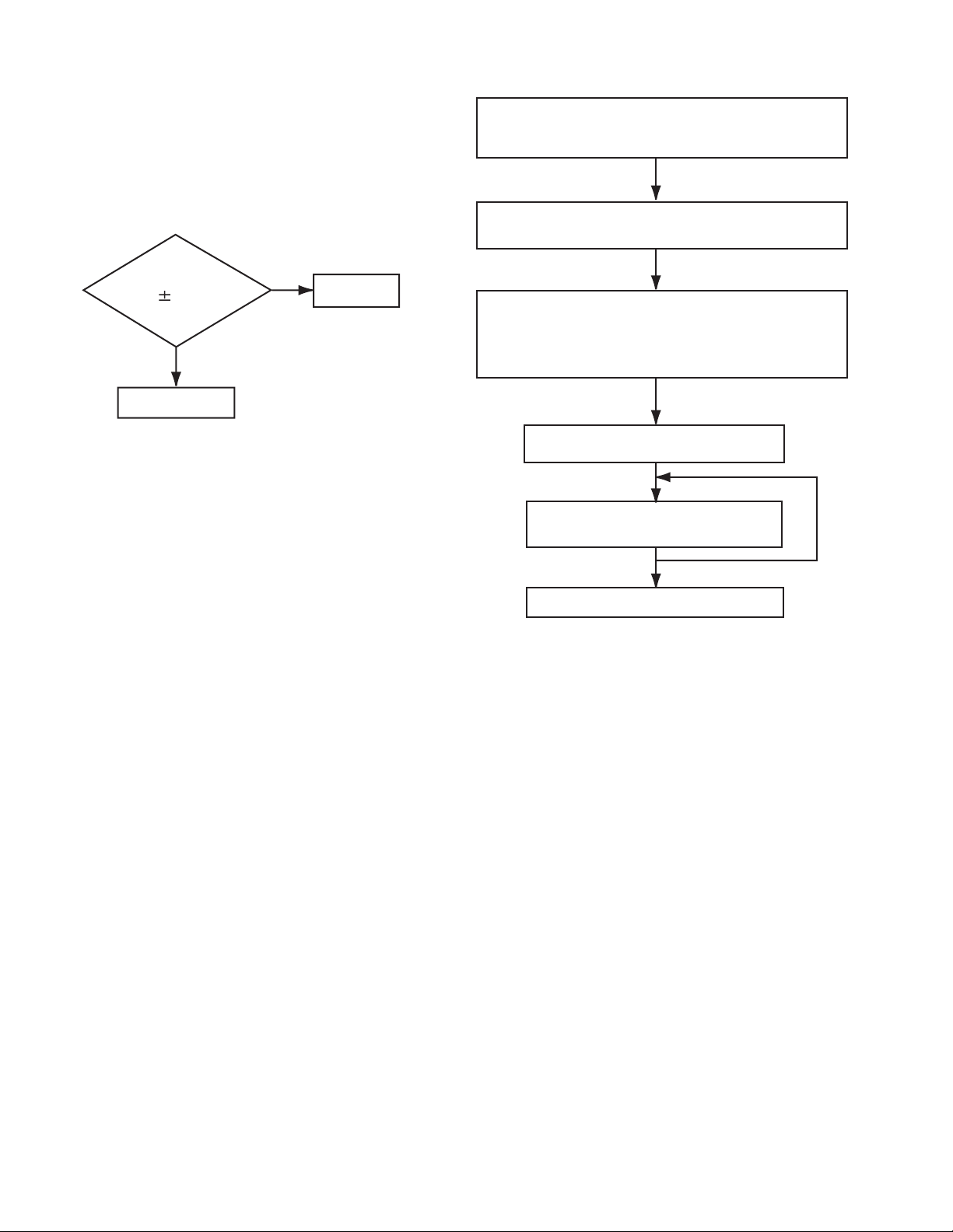
5.7 Replacement of laser pickup
Turn of the power switch and, disconnect the
power cord.
Replace the pickup with a normal one. (Refer
to "Removing the pickup unit" on the previous page.)
Is RF output
1.3 0.4Vp-p?
NO
Replace it.
YES
OK
(3) Semi-fixed resistor on the APC PC board
The semi-fixed resistor on the APC printed circuit board
which is attached to the pickup is used to adjust the laser
power.Since this adjustment should be performed to match
the characteristics of the whole optical block, do not touch
the semi-fixed resistor.
If the laser power is lower than the specified value, the laser diode is almost worn out, and the laser pickup should
be replaced. If the semi-fixed resistor is adjusted while the
pickup is functioning normally, the laser pickup may be
damaged due to excessive current.
Plug the power cord in, and turn the power on.
At this time, check that the laser emits for about
seconds and the objective lens moves up and down.
Note: Do not observe the laser beam directly.
Play a disc.
Check the eye-pattern at
RF test point.
Finish.
1-28 (No.MA142)
Page 29

5.8 16 PIN CORD DIAGRAM (KD-AR960)
8
7
6
5
4
3
2
1
BK
RD
NC
BL/WH
WH
GN
VI
GY
YL
OR/WH
NC
BR
WH/BK
GN/BK
VI/BK
GY/BK
16 YL
8 BK
7 RD
15 OR/WH
13 BR TEL
5 BL/WH
3 GN
16
15
14
13
12
11
10
9
MEMORY
GND
ACC
ILL
REMOTE
RL+
BK
RD
BL
WH
BR
CAUTION!
REMOTE
ONLY
OUTPUT
Black
Red
Blue
White
Brown
GN
VI
GY
YL
OR
Green
Violet
Gray
Yellow
Orange
GND
11 GN/BK
10 VI/BK
12 WH/BK
RR
FR
FL
RL
TEL
2 VI
4 WH
1 GY
9 GY/BK
Rear Right
Front Right
Front Left
Rear Left
Telephone muting
RL-
RR+
RR-
FL+
FL-
FR+
FR-
REMOTE
ACC
MEMORY
GND
ILL
Remote out
ACC Line
Memory Backup Battery +
Ground
Illuminations Control
(No.MA142)1-29
Page 30

5.9 16 PIN CORD DIAGRAM (KD-LH910)
8
7
6
BL/WH
5
4
3
2
1
BK
RD
NC
WH
GN
VI
GY
YL
OR/WH
NC
NC
WH/BK
GN/BK
VI/BK
GY/BK
16 YL
8 BK
7 RD
15 OR/WH
5 BL/WH
3 GN
16
15
14
13
12
11
10
9
MEMORY
GND
ACC
ILL
REMOTE
RL+
BK
RD
BL
WH
REMOTE
CAUTION!
ONLY
OUTPUT
Black
Red
Blue
White
GN
VI
GY
YL
OR
Green
Violet
Gray
Yellow
Orange
GND
11 GN/BK
2 VI
10 VI/BK
4 WH
12 WH/BK
1 GY
9 GY/BK
RR
FR
FL
RL
Rear Right
Front Right
Front Left
Rear Left
RL-
RR+
RR-
FL+
FL-
FR+
FR-
REMOTE
ACC
MEMORY
GND
ILL
Remote out
ACC Line
Memory Backup Battery +
Ground
Illuminations Control
1-30 (No.MA142)
Page 31

(No.MA142)1-31
Page 32

Victor Company of Japan, Limited
AV & MULTIMEDIA COMPANY CAR ELECTRONICS CATEGORY 10-1,1chome,Ohwatari-machi,Maebashi-city,371-8543,Japan
(No.MA142)
Printed in Japan
VPT
 Loading...