


 Loading...
SRX210 Services Gateway
Hardware Guide
Published: 2013-06-20
Copyright © 2013, Juniper Networks, Inc.

Juniper Networks, Inc.
1194 North Mathilda Avenue Sunnyvale, California 94089 USA
408-745-2000 www.juniper.net
ThisproductincludestheEnvoySNMPEngine,developedbyEpilogueTechnology,anIntegratedSystemsCompany. Copyright©1986-1997, Epilogue Technology Corporation. All rights reserved. This program and its documentation were developed at private expense, and no part of them is in the public domain.
This product includes memory allocation software developed by Mark Moraes, copyright © 1988, 1989, 1993, University of Toronto.
This product includes FreeBSD software developed by the University of California, Berkeley, and its contributors. All of the documentation and software included in the 4.4BSD and 4.4BSD-Lite Releases is copyrighted by the Regents of the University of California. Copyright © 1979, 1980, 1983, 1986, 1988, 1989, 1991, 1992, 1993, 1994. The Regents of the University of California. All rights reserved.
GateD software copyright © 1995, the Regents of the University. All rights reserved. Gate Daemon was originated and developed through release 3.0 by Cornell University and its collaborators. Gated is based on Kirton’s EGP, UC Berkeley’s routing daemon (routed), and DCN’s HELLO routing protocol. Development of Gated has been supported in part by the National Science Foundation. Portions of the GateD software copyright © 1988, Regents of the University of California. All rights reserved. Portions of the GateD software copyright © 1991, D. L. S. Associates.
This product includes software developed by Maker Communications, Inc., copyright © 1996, 1997, Maker Communications, Inc.
Juniper Networks, Junos, Steel-Belted Radius, NetScreen, and ScreenOS are registered trademarks of Juniper Networks, Inc. in the United States and other countries. The Juniper Networks Logo, the Junos logo, and JunosE are trademarks of Juniper Networks, Inc. All other trademarks, service marks, registered trademarks, or registered service marks are the property of their respective owners.
Juniper Networks assumes no responsibility for any inaccuracies in this document. Juniper Networks reserves the right to change, modify, transfer, or otherwise revise this publication without notice.
Products made or sold by Juniper Networks or components thereof might be covered by one or more of the following patents that are owned by or licensed to Juniper Networks: U.S. Patent Nos. 5,473,599, 5,905,725, 5,909,440, 6,192,051, 6,333,650, 6,359,479, 6,406,312, 6,429,706, 6,459,579, 6,493,347, 6,538,518, 6,538,899, 6,552,918, 6,567,902, 6,578,186, and 6,590,785.
SRX210 Services Gateway Hardware Guide
Copyright © 2013, Juniper Networks, Inc.
All rights reserved. Printed in USA.
Revision History
June 2013
The information in this document is current as of the date on the title page.
SOFTWARE LICENSE
The terms and conditions for using this software are described in the software license contained in the acknowledgment to your purchase order or, to the extent applicable, to any reseller agreement or end-user purchase agreement executed between you and Juniper Networks. By using this software, you indicate that you understand and agree to be bound by those terms and conditions.
Generally speaking, the software license restricts the manner in which you are permitted to use the software and may contain prohibitions against certain uses. The software license may state conditions under which the license is automatically terminated. You should consult the license for further details.
For complete product documentation, please see the Juniper Networks Web site at www.juniper.net/techpubs.
END USER LICENSE AGREEMENT
The Juniper Networks product that is the subject of this technical documentation consists of (or is intended for use with) Juniper Networks software. Use of such software is subject to the terms and conditions of the End User License Agreement (“EULA”) posted at
ii |
Copyright © 2013, Juniper Networks, Inc. |

http://www.juniper.net/support/eula.html. By downloading, installing or using such software, you agree to the terms and conditions of that EULA.
Copyright © 2013, Juniper Networks, Inc. |
iii |

iv |
Copyright © 2013, Juniper Networks, Inc. |

Table of Contents
About This Guide . . . . . . . . . . . . . . . . . . . . . . . . . . . . . . . . . . . . . . . . . . . . . . . . . . xi
Objectives . . . . . . . . . . . . . . . . . . . . . . . . . . . . . . . . . . . . . . . . . . . . . . . . . . . . . . xi
Audience . . . . . . . . . . . . . . . . . . . . . . . . . . . . . . . . . . . . . . . . . . . . . . . . . . . . . . . xi
Documentation Conventions . . . . . . . . . . . . . . . . . . . . . . . . . . . . . . . . . . . . . . . xi
SRX Series Documentation and Release Notes . . . . . . . . . . . . . . . . . . . . . . . xiii
Obtaining Documentation . . . . . . . . . . . . . . . . . . . . . . . . . . . . . . . . . . . . . . . . xiii
Documentation Feedback . . . . . . . . . . . . . . . . . . . . . . . . . . . . . . . . . . . . . . . . xiv
Requesting Technical Support . . . . . . . . . . . . . . . . . . . . . . . . . . . . . . . . . . . . . xiv
Part 1 |
SRX210 Services Gateway Overview |
|
Chapter 1 |
Introduction to the SRX210 Services Gateway . . . . . . . . . . . . . . . . . . . . . . . . |
. 3 |
|
SRX210 Services Gateway Description . . . . . . . . . . . . . . . . . . . . . . . . . . . . . . . . . . |
. 3 |
|
About the SRX210 Services Gateway . . . . . . . . . . . . . . . . . . . . . . . . . . . . . . . . |
. 3 |
|
SRX210 Services Gateway Models . . . . . . . . . . . . . . . . . . . . . . . . . . . . . . . . . . |
. 3 |
|
Accessing the SRX210 Services Gateway . . . . . . . . . . . . . . . . . . . . . . . . . . . . |
. 4 |
|
SRX210 Services Gateway Hardware Features . . . . . . . . . . . . . . . . . . . . . . . . . . . . |
. 4 |
Chapter 2 |
SRX210 Services Gateway Hardware Components and Specifications . . . |
. 7 |
|
SRX210 Services Gateway Specifications . . . . . . . . . . . . . . . . . . . . . . . . . . . . . . . . |
. 7 |
|
SRX210 Services Gateway Front Panel and Back Panel Views (Low Memory, |
|
|
High Memory, and PoE Versions) . . . . . . . . . . . . . . . . . . . . . . . . . . . . . . . . . . . |
. 9 |
|
SRX210 Services Gateway Front Panel . . . . . . . . . . . . . . . . . . . . . . . . . . . . . . |
. 9 |
|
SRX210 Services Gateway Back Panel . . . . . . . . . . . . . . . . . . . . . . . . . . . . . . . |
10 |
|
SRX210 Services Gateway Built-In Interfaces . . . . . . . . . . . . . . . . . . . . . . . . . . . . . |
. 11 |
|
SRX210 Services Gateway LEDs . . . . . . . . . . . . . . . . . . . . . . . . . . . . . . . . . . . . . . . . |
13 |
|
Front Panel LEDs . . . . . . . . . . . . . . . . . . . . . . . . . . . . . . . . . . . . . . . . . . . . . . . . |
14 |
|
Ethernet Port LEDs . . . . . . . . . . . . . . . . . . . . . . . . . . . . . . . . . . . . . . . . . . . . . . |
15 |
|
SRX210 Services Gateway Boot Devices and Dual-Root Partitioning Scheme . . . |
17 |
|
Boot Devices . . . . . . . . . . . . . . . . . . . . . . . . . . . . . . . . . . . . . . . . . . . . . . . . . . . . |
17 |
|
Dual-Root Partitioning Scheme . . . . . . . . . . . . . . . . . . . . . . . . . . . . . . . . . . . . |
17 |
|
SRX210 Services Gateway Cooling System . . . . . . . . . . . . . . . . . . . . . . . . . . . . . . . |
18 |
|
SRX210 Services Gateway Power Supply . . . . . . . . . . . . . . . . . . . . . . . . . . . . . . . . |
19 |
Chapter 3 |
SRX210 Services Gateway 3G ExpressCard . . . . . . . . . . . . . . . . . . . . . . . . . . . |
23 |
|
SRX210 Services Gateway 3G ExpressCard Overview . . . . . . . . . . . . . . . . . . . . . . |
23 |
|
Introduction . . . . . . . . . . . . . . . . . . . . . . . . . . . . . . . . . . . . . . . . . . . . . . . . . . . . |
23 |
|
Supported Modem Types . . . . . . . . . . . . . . . . . . . . . . . . . . . . . . . . . . . . . . . . . |
23 |
|
Using the 3G ExpressCard . . . . . . . . . . . . . . . . . . . . . . . . . . . . . . . . . . . . . . . . |
24 |
|
Key Features . . . . . . . . . . . . . . . . . . . . . . . . . . . . . . . . . . . . . . . . . . . . . . . . . . . |
24 |
Copyright © 2013, Juniper Networks, Inc. |
v |

SRX210 Services Gateway Hardware Guide
|
Physical Specifications . . . . . . . . . . . . . . . . . . . . . . . . . . . . . . . . . . . . . . . . . . . |
25 |
|
Installing the 3G ExpressCard in the SRX210 Services Gateway ExpressCard |
|
|
Slot . . . . . . . . . . . . . . . . . . . . . . . . . . . . . . . . . . . . . . . . . . . . . . . . . . . . . . . . . . |
26 |
|
SRX210 Services Gateway 3G ExpressCard Basic CLI Commands . . . . . . . . . . . . |
27 |
Chapter 4 |
SRX210 Services Gateway Power over Ethernet Support . . . . . . . . . . . . . . . |
29 |
|
SRX210 Services Gateway PoE Overview . . . . . . . . . . . . . . . . . . . . . . . . . . . . . . . . |
29 |
|
Introduction . . . . . . . . . . . . . . . . . . . . . . . . . . . . . . . . . . . . . . . . . . . . . . . . . . . . |
29 |
|
PoE Classes and Power Ratings . . . . . . . . . . . . . . . . . . . . . . . . . . . . . . . . . . . . |
30 |
|
Configuring PoE Functionality on the SRX210 Services Gateway . . . . . . . . . . . . . . |
31 |
Chapter 5 |
SRX210 Services Gateway Mini-Physical Interface Modules . . . . . . . . . . . . |
33 |
|
SRX210 Services Gateway Mini-Physical Interface Modules . . . . . . . . . . . . . . . . . |
33 |
Part 2 |
Setting Up the SRX210 Services Gateway |
|
Chapter 6 |
Preparing the Site for the SRX210 Services Gateway Installation . . . . . . . . |
37 |
|
Site Preparation Checklist for the SRX210 Services Gateway . . . . . . . . . . . . . . . . |
37 |
|
General Site Guidelines for Installing the SRX210 Services Gateway . . . . . . . . . . |
39 |
|
SRX210 Services Gateway Cabinet Requirements . . . . . . . . . . . . . . . . . . . . . . . . . |
39 |
|
SRX210 Services Gateway Rack Requirements . . . . . . . . . . . . . . . . . . . . . . . . . . . |
40 |
|
Clearance Requirements for Airflow and Hardware Maintenance of the SRX210 |
|
|
Services Gateway . . . . . . . . . . . . . . . . . . . . . . . . . . . . . . . . . . . . . . . . . . . . . . . |
41 |
|
SRX210 Services Gateway Electrical and Power Requirements . . . . . . . . . . . . . . |
42 |
Chapter 7 |
Installation Overview for the SRX210 Services Gateway . . . . . . . . . . . . . . . |
45 |
|
Installation Overview for the SRX210 Services Gateway . . . . . . . . . . . . . . . . . . . . |
45 |
Chapter 8 |
Required Tools and Parts for Installing and Maintaining the SRX210 |
|
|
Services Gateway . . . . . . . . . . . . . . . . . . . . . . . . . . . . . . . . . . . . . . . . . . . . . . . . . |
47 |
|
Required Tools and Parts for Installing and Maintaining the SRX210 Services |
|
|
Gateway . . . . . . . . . . . . . . . . . . . . . . . . . . . . . . . . . . . . . . . . . . . . . . . . . . . . . . . |
47 |
Chapter 9 |
Unpacking the SRX210 Services Gateway . . . . . . . . . . . . . . . . . . . . . . . . . . . . |
49 |
|
Unpacking the SRX210 Services Gateway . . . . . . . . . . . . . . . . . . . . . . . . . . . . . . . |
49 |
|
Verifying Parts Received with the SRX210 Services Gateway . . . . . . . . . . . . . . . . |
49 |
Chapter 10 |
Preparing the SRX210 Services Gateway for Installation . . . . . . . . . . . . . . . |
53 |
|
Preparing the SRX210 Services Gateway for Rack-Mount, Desk-Mount, and |
|
|
Wall-Mount Installation . . . . . . . . . . . . . . . . . . . . . . . . . . . . . . . . . . . . . . . . . . |
53 |
|
Preparing the SRX210 Services Gateway for Rack-Mount Installation . . . . . . . . . |
53 |
|
Preparing the SRX210 Services Gateway for Desk-Mount Installation . . . . . . . . . |
55 |
|
Preparing the SRX210 Services Gateway for Wall-Mount Installation . . . . . . . . . |
56 |
Chapter 11 |
Installing the SRX210 Services Gateway . . . . . . . . . . . . . . . . . . . . . . . . . . . . . |
57 |
|
SRX210 Services Gateway Safety Requirements, Warnings, and Guidelines . . . . |
57 |
|
SRX210 Services Gateway Installation . . . . . . . . . . . . . . . . . . . . . . . . . . . . . . . . . . |
57 |
|
Adjusting the Power Supply Adapter Tray for the SRX210 Services Gateway |
|
|
for Rack-Mount Installation . . . . . . . . . . . . . . . . . . . . . . . . . . . . . . . . . . . |
58 |
|
Installing the SRX210 Services Gateway in a Rack . . . . . . . . . . . . . . . . . . . . . |
59 |
|
Installing the SRX210 Services Gateway on a Desk . . . . . . . . . . . . . . . . . . . . . |
62 |
vi |
Copyright © 2013, Juniper Networks, Inc. |

Table of Contents
|
Installing the SRX210 Services Gateway on a Wall . . . . . . . . . . . . . . . . . . . . . |
63 |
|
Replacing or Installing Mini-Physical Interface Modules in the SRX210 Services |
|
|
Gateway . . . . . . . . . . . . . . . . . . . . . . . . . . . . . . . . . . . . . . . . . . . . . . . . . . . . . . |
66 |
Chapter 12 |
Connecting, Grounding, and Powering On the SRX210 Services |
|
|
Gateway . . . . . . . . . . . . . . . . . . . . . . . . . . . . . . . . . . . . . . . . . . . . . . . . . . . . . . . . . |
67 |
|
Connecting the SRX210 Services Gateway to the Power Supply . . . . . . . . . . . . . . |
67 |
|
Connecting and Organizing Interface Cables for the SRX210 Services |
|
|
Gateway . . . . . . . . . . . . . . . . . . . . . . . . . . . . . . . . . . . . . . . . . . . . . . . . . . . . . . |
68 |
|
Grounding the SRX210 Services Gateway . . . . . . . . . . . . . . . . . . . . . . . . . . . . . . . . |
70 |
|
Powering On and Powering Off the SRX210 Services Gateway . . . . . . . . . . . . . . |
. 71 |
|
Powering On the SRX210 Services Gateway . . . . . . . . . . . . . . . . . . . . . . . . . . |
. 71 |
|
Powering Off the SRX210 Services Gateway . . . . . . . . . . . . . . . . . . . . . . . . . . |
72 |
|
Resetting the SRX210 Services Gateway . . . . . . . . . . . . . . . . . . . . . . . . . . . . . |
73 |
Chapter 13 |
SRX210 Services Gateway Autoinstallation . . . . . . . . . . . . . . . . . . . . . . . . . . . |
75 |
|
SRX210 Services Gateway Autoinstallation Overview . . . . . . . . . . . . . . . . . . . . . . |
75 |
Chapter 14 |
Connecting the SRX210 Services Gateway to Management Devices . . . . . |
77 |
|
Connecting an SRX210 Services Gateway to the J-Web Interface . . . . . . . . . . . . . |
77 |
|
Connecting an SRX210 Services Gateway to the CLI Locally . . . . . . . . . . . . . . . . . |
79 |
|
Connecting an SRX210 Services Gateway to the CLI Remotely . . . . . . . . . . . . . . |
80 |
|
Connecting the Modem at the SRX210 Services Gateway End . . . . . . . . . . . . . . . |
81 |
|
Connecting the Modem to the Console Port on the SRX210 Services |
|
|
Gateway . . . . . . . . . . . . . . . . . . . . . . . . . . . . . . . . . . . . . . . . . . . . . . . . . . . . . . |
82 |
|
Connecting to the CLI at the User End for the SRX210 Services Gateway . . . . . . . |
83 |
Chapter 15 |
Performing Initial Software Configuration on the SRX210 Services |
|
|
Gateway . . . . . . . . . . . . . . . . . . . . . . . . . . . . . . . . . . . . . . . . . . . . . . . . . . . . . . . . . |
85 |
|
SRX210 Services Gateway Software Configuration Overview . . . . . . . . . . . . . . . . |
85 |
|
Preparing the SRX210 Services Gateway for Configuration . . . . . . . . . . . . . . |
85 |
|
Understanding the Factory-Default Configuration . . . . . . . . . . . . . . . . . . . . . |
86 |
|
Understanding Built-In Ethernet Ports and Initial Configuration . . . . . . . . . . |
86 |
|
Mapping the Chassis Cluster Ports . . . . . . . . . . . . . . . . . . . . . . . . . . . . . . . . . . |
87 |
|
Understanding Management Access . . . . . . . . . . . . . . . . . . . . . . . . . . . . . . . . |
88 |
|
Performing Initial Software Configuration on the SRX210 Services Gateway |
|
|
Using the CLI . . . . . . . . . . . . . . . . . . . . . . . . . . . . . . . . . . . . . . . . . . . . . . . . . . . |
89 |
|
Performing Initial Software Configuration on the SRX210 Services Gateway |
|
|
Using the J-Web Interface . . . . . . . . . . . . . . . . . . . . . . . . . . . . . . . . . . . . . . . . . |
91 |
|
Establishing Basic Connectivity . . . . . . . . . . . . . . . . . . . . . . . . . . . . . . . . . . . . |
92 |
|
Configuring Basic System Properties . . . . . . . . . . . . . . . . . . . . . . . . . . . . . . . . |
93 |
|
SRX210 Services Gateway Secure Web Access Overview . . . . . . . . . . . . . . . . . . . |
95 |
Part 3 |
Maintaining and Monitoring the SRX210 Services Gateway |
|
|
Hardware |
|
Chapter 16 |
Maintaining the SRX210 Services Gateway Hardware Components . . . . . |
99 |
|
Maintaining the SRX210 Services Gateway Hardware Components . . . . . . . . . . . |
99 |
Copyright © 2013, Juniper Networks, Inc. |
vii |

SRX210 Services Gateway Hardware Guide
Chapter 17 |
Monitoring the SRX210 Services Gateway . . . . . . . . . . . . . . . . . . . . . . . . . . . |
101 |
|
Monitoring Hardware Components on the SRX210 Services Gateway . . . . . . . . . |
101 |
|
Monitoring the SRX210 Services Gateway Chassis Using the CLI . . . . . . . . . |
101 |
|
Monitoring the SRX210 Services Gateway Components Using LEDs . . . . . . |
103 |
|
Monitoring the SRX210 Services Gateway Using Chassis Alarm |
|
|
Conditions . . . . . . . . . . . . . . . . . . . . . . . . . . . . . . . . . . . . . . . . . . . . . . . . |
105 |
|
Monitoring the SRX210 Services Gateway Power System . . . . . . . . . . . . . . . |
108 |
|
Resetting the Configuration File When the SRX210 Services Gateway Is |
|
|
Inaccessible . . . . . . . . . . . . . . . . . . . . . . . . . . . . . . . . . . . . . . . . . . . . . . . . . . . |
109 |
|
Using the Reset Config Button on the SRX210 Services Gateway . . . . . . . . |
109 |
|
Changing the Reset Config Button Behavior on the SRX210 Services |
|
|
Gateway . . . . . . . . . . . . . . . . . . . . . . . . . . . . . . . . . . . . . . . . . . . . . . . . . . |
110 |
|
Juniper Networks Technical Assistance Center . . . . . . . . . . . . . . . . . . . . . . . . . . . |
110 |
Part 4 |
Appendixes |
|
Appendix A |
Safety and Regulatory Compliance Information . . . . . . . . . . . . . . . . . . . . . . |
113 |
|
SRX210 Services Gateway Definition of Safety Warning Levels . . . . . . . . . . . . . . |
113 |
|
SRX210 Services Gateway General Safety Guidelines and Warnings . . . . . . . . . . |
115 |
|
General Safety Guidelines and Warnings . . . . . . . . . . . . . . . . . . . . . . . . . . . . |
115 |
|
Qualified Personnel Warning . . . . . . . . . . . . . . . . . . . . . . . . . . . . . . . . . . . . . . |
116 |
|
Restricted Access Area Warning . . . . . . . . . . . . . . . . . . . . . . . . . . . . . . . . . . . . |
117 |
|
Preventing Electrostatic Discharge Damage to the Services Gateway . . . . . |
118 |
|
SRX210 Services Gateway Fire Safety Requirements . . . . . . . . . . . . . . . . . . . . . . |
119 |
|
SRX210 Services Gateway Installation Safety Guidelines and Warnings . . . . . . . |
120 |
|
SRX210 Services Gateway Laser and LED Safety Guidelines and Warnings . . . . |
124 |
|
Laser and LED Safety Guidelines and Warnings . . . . . . . . . . . . . . . . . . . . . . . |
124 |
|
General Laser Safety Guidelines . . . . . . . . . . . . . . . . . . . . . . . . . . . . . . . |
124 |
|
Class 1 Laser Product Warning . . . . . . . . . . . . . . . . . . . . . . . . . . . . . . . . . |
125 |
|
Class 1 LED Product Warning . . . . . . . . . . . . . . . . . . . . . . . . . . . . . . . . . . |
125 |
|
Laser Beam Warning . . . . . . . . . . . . . . . . . . . . . . . . . . . . . . . . . . . . . . . . |
126 |
|
Radiation from Open Port Apertures Warning . . . . . . . . . . . . . . . . . . . . |
126 |
|
SRX210 Services Gateway Maintenance and Operational Safety Guidelines and |
|
|
Warnings . . . . . . . . . . . . . . . . . . . . . . . . . . . . . . . . . . . . . . . . . . . . . . . . . . . . . . |
127 |
|
Safety Guidelines and Warnings . . . . . . . . . . . . . . . . . . . . . . . . . . . . . . . . . . . |
127 |
|
Battery Handling Warning . . . . . . . . . . . . . . . . . . . . . . . . . . . . . . . . . . . . |
127 |
|
Jewelry Removal Warning . . . . . . . . . . . . . . . . . . . . . . . . . . . . . . . . . . . . |
128 |
|
Lightning Activity Warning . . . . . . . . . . . . . . . . . . . . . . . . . . . . . . . . . . . . |
130 |
|
Operating Temperature Warning . . . . . . . . . . . . . . . . . . . . . . . . . . . . . . . |
130 |
|
Product Disposal Warning . . . . . . . . . . . . . . . . . . . . . . . . . . . . . . . . . . . . . |
131 |
|
SRX210 Services Gateway Electrical Safety Guidelines and Warnings . . . . . . . . . |
132 |
|
SRX210 Services Gateway Agency Approvals . . . . . . . . . . . . . . . . . . . . . . . . . . . . |
133 |
|
SRX210 Services Gateway Compliance Statements for EMC Requirements . . . . |
134 |
|
SRX210 Services Gateway Compliance Statements for Environmental |
|
|
Requirements . . . . . . . . . . . . . . . . . . . . . . . . . . . . . . . . . . . . . . . . . . . . . . . . . . |
137 |
|
SRX210 Services Gateway Compliance Statements for Acoustic Noise . . . . . . . |
137 |
viii |
Copyright © 2013, Juniper Networks, Inc. |

Table of Contents
Appendix B |
SRX210 Services Gateway Power Guidelines, Requirements, and |
|
|
Specifications . . . . . . . . . . . . . . . . . . . . . . . . . . . . . . . . . . . . . . . . . . . . . . . . . . . |
139 |
|
SRX210 Services Gateway Site Electrical Wiring Guidelines . . . . . . . . . . . . . . . . . |
139 |
|
SRX210 Services Gateway Power Specifications and Requirements . . . . . . . . . |
. 141 |
|
SRX210 Services Gateway Grounding Specifications . . . . . . . . . . . . . . . . . . . . . . |
141 |
Appendix C |
SRX210 Services Gateway Interface Cable Specifications and Connector |
|
|
Pinouts . . . . . . . . . . . . . . . . . . . . . . . . . . . . . . . . . . . . . . . . . . . . . . . . . . . . . . . . . |
143 |
|
Interface Cable and Wire Specifications for the SRX210 Services Gateway . . . . |
143 |
|
RJ-45 Connector Pinouts for the SRX210 Services Gateway Ethernet Port . . . . . |
144 |
|
RJ-45 Connector Pinouts for the SRX210 Services Gateway Console Port . . . . . |
145 |
Appendix D |
Contacting Customer Support and Returning the SRX210 Services |
|
|
Gateway Hardware . . . . . . . . . . . . . . . . . . . . . . . . . . . . . . . . . . . . . . . . . . . . . . . |
147 |
|
Return Procedure for the SRX210 Services Gateway . . . . . . . . . . . . . . . . . . . . . . . |
147 |
|
Locating an SRX210 Services Gateway Component Serial Number and Agency |
|
|
Labels . . . . . . . . . . . . . . . . . . . . . . . . . . . . . . . . . . . . . . . . . . . . . . . . . . . . . . . |
148 |
|
Listing the SRX210 Services Gateway and Component Details with the |
|
|
CLI . . . . . . . . . . . . . . . . . . . . . . . . . . . . . . . . . . . . . . . . . . . . . . . . . . . . . . . |
148 |
|
SRX210 Services Gateway Chassis Serial Number and Agency Labels . . . . |
149 |
|
SRX210 Services Gateway Mini-Physical Interface Module Serial Number |
|
|
Label . . . . . . . . . . . . . . . . . . . . . . . . . . . . . . . . . . . . . . . . . . . . . . . . . . . . . |
149 |
|
Contacting Customer Support to Obtain Return Materials Authorization . . . . . . |
150 |
|
Information You Might Need to Supply to Juniper Networks Technical |
|
|
Assistance Center . . . . . . . . . . . . . . . . . . . . . . . . . . . . . . . . . . . . . . . . . . |
150 |
|
Contacting Customer Support . . . . . . . . . . . . . . . . . . . . . . . . . . . . . . . . . . . . |
150 |
|
Packing the SRX210 Services Gateway and Components for Shipment . . . . . . . |
151 |
|
Packing the Services Gateway . . . . . . . . . . . . . . . . . . . . . . . . . . . . . . . . . . . . . |
151 |
|
Packing the Components for Shipment . . . . . . . . . . . . . . . . . . . . . . . . . . . . . |
152 |
Part 5 |
Index |
|
|
Index . . . . . . . . . . . . . . . . . . . . . . . . . . . . . . . . . . . . . . . . . . . . . . . . . . . . . . . . . . . . |
155 |
Copyright © 2013, Juniper Networks, Inc. |
ix |

SRX210 Services Gateway Hardware Guide
x |
Copyright © 2013, Juniper Networks, Inc. |
About This Guide
This preface includes the following topics:
•Objectives on page xi
•Audience on page xi
•Documentation Conventions on page xi
•SRX Series Documentation and Release Notes on page xiii
•Obtaining Documentation on page xiii
•Documentation Feedback on page xiv
•Requesting Technical Support on page xiv
Objectives
This guide describes hardware components and installation, basic configuration, and basic troubleshooting procedures for the Juniper Networks SRX210 Services Gateway. It explains how to prepare your site for services gateway installation, unpack and install thehardware,powerontheservicesgateway,performinitialsoftwareconfiguration,and perform routine maintenance. After completing the installation and basic configuration procedures covered in this guide, see the Junos OS configuration guides for information about further Junos OS configuration.
Audience
This guide is designed for network administrators who are installing and maintaining a Juniper Networks SRX210 Services Gateway or preparing a site for device installation. Tousethisguide,youneedabroadunderstandingofnetworksingeneralandtheInternet in particular, networking principles, and network configuration. Any detailed discussion of these concepts is beyond the scope of this guide.
Documentation Conventions
Table 1 on page xii defines the notice icons used in this guide.
Copyright © 2013, Juniper Networks, Inc. |
xi |
SRX210 Services Gateway Hardware Guide
Table 1: Notice Icons
Icon |
Meaning |
Description |
|
Informational note |
Indicates important features or instructions. |
|
Caution |
Indicates a situation that might result in loss of data or hardware damage. |
|
Warning |
Alerts you to the risk of personal injury or death. |
|
Laser warning |
Alerts you to the risk of personal injury from a laser. |
Table 2 on page xii defines the text and syntax conventions used in this guide.
Table 2: Text and Syntax Conventions
Convention |
Description |
|
Bold text like this |
Represents text that you type. |
|
Fixed-width text like this |
Represents output that appears on the |
|
|
terminal screen. |
|
Italic text like this |
• Introduces or emphasizes important |
|
|
|
new terms. |
|
• |
Identifies book names. |
|
• |
IdentifiesRFCandInternetdrafttitles. |
Italic text like this |
Represents variables (options for which |
|
|
you substitute a value) in commands or |
|
|
configuration statements. |
|
Examples
To enter configuration mode, type theconfigure command:
user@host> configure
user@host> show chassis alarms
No alarms currently active
•A policy term is a named structure that defines match conditions and actions.
•JunosOSSystemBasicsConfiguration Guide
•RFC1997, BGPCommunitiesAttribute
Configure the machine’s domain name:
[edit]
root@# set system domain-name domain-name
Text like this |
Represents names of configuration |
|
statements, commands, files, and |
|
directories;configurationhierarchylevels; |
|
or labels on routing platform |
|
components. |
•To configure a stub area, include the stub statement at the[edit protocols ospf area area-id] hierarchy level.
•TheconsoleportislabeledCONSOLE.
< > (angle brackets) |
Enclose optional keywords or variables. |
stub <default-metric metric>; |
xii |
Copyright © 2013, Juniper Networks, Inc. |

About This Guide
Table 2: Text and Syntax Conventions (continued)
Convention |
Description |
Examples |
| (pipe symbol) |
Indicates a choice between the mutually |
broadcast | multicast |
|
exclusivekeywordsorvariablesoneither |
|
|
side of the symbol. The set of choices is |
(string1 | string2 | string3) |
|
often enclosed in parentheses for clarity. |
|
# (pound sign) |
Indicates a comment specified on the |
rsvp { # Required for dynamic MPLS only |
|
samelineastheconfigurationstatement |
|
|
to which it applies. |
|
[ ] (square brackets) |
Enclose a variable for which you can |
|
substitute one or more values. |
Indention and braces ( { } ) |
Identify a level in the configuration |
|
hierarchy. |
; (semicolon) |
Identifies a leaf statement at a |
|
configuration hierarchy level. |
GUI Conventions
Bold text like this |
Representsgraphicaluserinterface(GUI) |
|
items you click or select. |
> (bold right angle bracket) |
Separates levels in a hierarchy of menu |
|
selections. |
community name members [ community-ids ]
[edit] routing-options {
static {
route default { nexthop address; retain;
}
}
}
•In the Logical Interfaces box, select
All Interfaces.
•To cancel the configuration, click
Cancel.
In the configuration editor hierarchy, select Protocols>Ospf.
SRX Series Documentation and Release Notes
For a list of related SRX Series documentation, see
http://www.juniper.net/techpubs/hardware/srx-series-main.html.
If the information in the latest SRX Series Release Notes differs from the information in the documentation, follow the SRX Series Release Notes.
Obtaining Documentation
To obtain the most current version of all Juniper Networks technical documentation, see the products documentation page on the Juniper Networks web site at http://www.juniper.net/techpubs.
To order printed copies of this guide and other Juniper Networks technical documents, or to order a documentation CD, which contains this guide, contact your sales representative.
Copyright © 2013, Juniper Networks, Inc. |
xiii |

SRX210 Services Gateway Hardware Guide
Copies of the Management Information Bases (MIBs) available in a software release are included on the documentation CDs and at http://www.juniper.net/.
Documentation Feedback
We encourage you to provide feedback, comments, and suggestions so that we can improve the documentation. You can send your comments to techpubs-comments@juniper.net, or fill out the documentation feedback form at http://www.juniper.net/techpubs/docbug/docbugreport.html. If you are using e-mail, be sure to include the following information with your comments:
•Document name
•Document part number
•Page number
•Software release version (not required for Network Operations Guides [NOGs])
Requesting Technical Support
TechnicalproductsupportisavailablethroughtheJuniperNetworksTechnicalAssistance Center (JTAC). If you are a customer with an active J-Care or JNASC support contract, or are covered under warranty, and need postsales technical support, you can access our tools and resources online or open a case with JTAC.
•JTAC policiesFor a complete understanding of our JTAC procedures and policies, review the JTAC User Guide located at http://www.juniper.net/customers/support/downloads/710059.pdf.
•Product warrantiesFor product warranty information, visit http://www.juniper.net/support/warranty/.
•JTAC Hours of OperationThe JTAC centers have resources available 24 hours a day, 7 days a week, 365 days a year.
Self-Help Online Tools and Resources
For quick and easy problem resolution, Juniper Networks has designed an online self-service portal called the Customer Support Center (CSC) that provides you with the following features:
•Find CSC offerings: http://www.juniper.net/customers/support/
•Search for known bugs: http://www2.juniper.net/kb/
•Find product documentation: http://www.juniper.net/techpubs/
•Find solutions and answer questions using our Knowledge Base: http://kb.juniper.net/
•Download the latest versions of software and review release notes: http://www.juniper.net/customers/csc/software/
•Search technical bulletins for relevant hardware and software notifications: https://www.juniper.net/alerts/
xiv |
Copyright © 2013, Juniper Networks, Inc. |

About This Guide
•Join and participate in the Juniper Networks Community Forum: http://www.juniper.net/company/communities/
•Open a case online in the CSC Case Manager: http://www.juniper.net/cm/
Toverifyserviceentitlementbyproductserialnumber,useourSerialNumberEntitlement (SNE) tool located at https://tools.juniper.net/SerialNumberEntitlementSearch/.
Opening a Case with JTAC
You can open a case with JTAC on the Web or by telephone.
•Use the Case Manager tool in the CSC at http://www.juniper.net/cm/.
•Call 1-888-314-JTAC (1-888-314-5822 toll-free in the USA, Canada, and Mexico).
For international or direct-dial options in countries without toll-free numbers, visit us at http://www.juniper.net/support/requesting-support.html.
Copyright © 2013, Juniper Networks, Inc. |
xv |

SRX210 Services Gateway Hardware Guide
xvi |
Copyright © 2013, Juniper Networks, Inc. |

PART 1
SRX210 Services Gateway Overview
•Introduction to the SRX210 Services Gateway on page 3
•SRX210 Services Gateway Hardware Components and Specifications on page 7
•SRX210 Services Gateway 3G ExpressCard on page 23
•SRX210 Services Gateway Power over Ethernet Support on page 29
•SRX210 Services Gateway Mini-Physical Interface Modules on page 33
Copyright © 2013, Juniper Networks, Inc. |
1 |

SRX210 Services Gateway Hardware Guide
2 |
Copyright © 2013, Juniper Networks, Inc. |

CHAPTER 1
Introduction to the SRX210 Services Gateway
This chapter includes the following topics:
•SRX210 Services Gateway Description on page 3
•SRX210 Services Gateway Hardware Features on page 4
SRX210 Services Gateway Description
This topic includes the following sections:
•About the SRX210 Services Gateway on page 3
•SRX210 Services Gateway Models on page 3
•Accessing the SRX210 Services Gateway on page 4
About the SRX210 Services Gateway
The Juniper Networks SRX210 Services Gateway offers complete functionality and flexibility for delivering secure and reliable data, along with multiple interfaces that support WAN and LAN connectivity and Power over Ethernet (PoE).
TheSRX210ServicesGatewayprovidesInternetProtocolSecurity(IPsec),virtualprivate network (VPN), and firewall services for small and medium-sized companies and enterprise branch and remote offices. Additional security features also include Unified ThreatManagement(UTM),whichconsistsofIPSantispam,antivirus,andWebfiltering.
The SRX210 Services Gateway runs the Junos operating system (Junos OS).
SRX210 Services Gateway Models
The SRX210 Services Gateway is available in six models, which are listed in
Table 3 on page 3.
Table 3: SRX210 Services Gateway Models
Product Name |
Device Type |
Model Number |
SRX210 Services Gateway |
Low Memory |
SRX210B |
Copyright © 2013, Juniper Networks, Inc. |
3 |

SRX210 Services Gateway Hardware Guide
Table 3: SRX210 Services Gateway Models (continued)
Product Name |
Device Type |
Model Number |
SRX210 Services Gateway |
High Memory |
SRX210H |
SRX210 Services Gateway with |
High Memory with Power over |
SRX210H-POE |
PoE |
Ethernet (PoE) |
|
SRX210 Services Gateway |
Low Memory (Enhanced) |
SRX210BE |
(Enhanced) |
|
|
SRX210 Services Gateway High |
High Memory (Enhanced) |
SRX210HE |
Memory (Enhanced) |
|
|
SRX210 Services Gateway |
High Memory (Enhanced + TAA |
SRX210HE-TAA |
(Enhanced) TAA Compliant |
Compliant) |
|
SRX210 Services Gateway with |
High Memory with Power over |
SRX210HE-POE |
PoE (Enhanced) |
Ethernet (Enhanced + PoE) |
|
SRX210 Services Gateway with |
High Memory with PoE |
SRX210HE-POE-TAA |
PoE (Enhanced + TAA) |
(Enhanced + TAA Compliant) |
|
All SRX210 Services Gateways run the Junos operating system (Junos OS).
Accessing the SRX210 Services Gateway
Two user interfaces are available for monitoring, configuring, troubleshooting, and managing the SRX210 Services Gateway:
•J-Web interface: Web-based graphical interface that allows you to operate a services gateway without commands. The J-Web interface provides access to all Junos functionality and features.
•Junos OS command-line interface (CLI): Juniper Networks command shell that runs ontopofaUNIX-basedoperatingsystemkernel.TheCLIisastraightforwardcommand interface. On a single line, you type commands that are executed when you press the Enter key. The CLI provides command Help and command completion.
Related |
• |
SRX210 Services Gateway Specifications on page 7 |
Documentation |
• |
SRX210 Services Gateway Hardware Features on page 4 |
SRX210 Services Gateway Hardware Features
Table 4 on page 5 lists the hardware features supported on the SRX210 Services
Gateway.
4 |
Copyright © 2013, Juniper Networks, Inc. |
Chapter 1: Introduction to the SRX210 Services Gateway
Table 4: SRX210 Services Gateway Hardware Features
|
SRX210 Services |
SRX210 Services |
SRX210 Services |
|
Gateway Low |
Gateway High |
GatewayPowerover |
Feature |
Memory |
Memory |
Ethernet |
DDR memory |
512 MB |
1 GB |
1 GB |
PoE support |
No |
No |
Yes |
Power supply adapter |
60 watts |
60 watts |
150 watts |
NOTE: The SRX210 |
|
|
|
ServicesGatewayuses |
|
|
|
a single power supply. |
|
|
|
AC input voltage |
100 to 240 VAC |
100 to 240 VAC |
100 to 240 VAC |
Gigabit Ethernet ports |
2 |
2 |
2 |
Fast Ethernet ports |
6 |
6 |
6 |
Console port |
1 |
1 |
1 |
USB ports |
2 |
2 |
2 |
Mini-PIM slots |
1 |
1 |
1 |
LEDs |
Status, Alarm, HA, |
Status, Alarm, HA, |
Status, Alarm, HA, |
|
Power, Mini-PIMs, 3G |
Power,Mini-PIMs,3G |
Power, Mini-PIMs, 3G |
|
ExpressCard, Port |
ExpressCard, Port |
ExpressCard, Port |
|
(TX/RX and PoE) |
(TX/RX and PoE) |
(TX/RX and PoE) |
NAND flash |
1 GB |
1 GB |
1 GB |
Fans |
1 |
1 |
1 |
NOTE: ThePoELEDisenabledonlyonthePoEmodeloftheSRX210Services
Gateway. For non-PoE services gateways, the PoE LED remains off.
For more details on the SRX210 Services Gateway software features and licenses, see the following guides:
•Initial Configuration for Security Devices
•Monitoring and Troubleshooting for Security Devices
Related • SRX210 Services Gateway Description on page 3
Documentation • SRX210 Services Gateway Specifications on page 7
Copyright © 2013, Juniper Networks, Inc. |
5 |

SRX210 Services Gateway Hardware Guide
6 |
Copyright © 2013, Juniper Networks, Inc. |
CHAPTER 2
SRX210 Services Gateway Hardware
Components and Specifications
This chapter includes the following topics:
•SRX210 Services Gateway Specifications on page 7
•SRX210 Services Gateway Front Panel and Back Panel Views (Low Memory, High Memory, and PoE Versions) on page 9
•SRX210 Services Gateway Built-In Interfaces on page 11
•SRX210 Services Gateway LEDs on page 13
•SRX210ServicesGatewayBootDevicesandDual-RootPartitioningSchemeonpage17
•SRX210 Services Gateway Cooling System on page 18
•SRX210 Services Gateway Power Supply on page 19
SRX210 Services Gateway Specifications
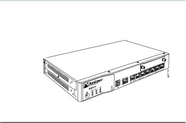
The SRX210 Services Gateway chassis is a rigid sheet metal structure of 1 rack unit (U) height that houses all the other hardware components.
Figure 1 on page 7 shows the SRX210 Services Gateway chassis (for low memory, high memory, and PoE models).
Figure 1: SRX210 Services Gateway
Copyright © 2013, Juniper Networks, Inc. |
7 |

SRX210 Services Gateway Hardware Guide
Table 5 on page 8 provides information on the physical specifications of the device.
Table 5: SRX210 Services Gateway Specifications
Specification |
Value |
Dimensions (H x W x D) |
1.73 in. x 11.02 in. x 7.13 in. |
|
44 mm x 280 mm x 181 mm |
Chassis weight |
• 3.46 lb (1.57 kg) for SRX210 Services Gateway |
|
without PoE (no interface modules) |
|
• 3.55 lb (1.61 kg) for SRX210 Services Gateway with |
|
PoE (no interface modules) |
Average power consumption |
• SRX210 Services Gateway Low Memory model: 27 |
|
watts |
|
• SRX210ServicesGatewayHighMemorymodel:28 |
|
watts |
|
• SRX210 Services Gateway PoE model: 34 watts |
|
(excluding PoE load) |
Altitude |
No performance degradation up to 10,000 ft (3048 |
|
m) for SRX210 Services Gateway Low Memory, High |
|
Memory, and PoE models |
Relative humidity |
5% to 90%, noncondensing |
Temperature |
Normal operation ensured in temperature range of |
|
32°F (0°C) to 104°F (+40°C) |
|
Nonoperating storage temperature in shipping |
|
container: –40°F (–40°C) to 158°F (70°C) |
Maximum thermal output |
NOTE: Thesespecificationsareestimatesandsubject |
|
to change. |
|
• SRX210 Services Gateway Low Memory: 120 |
|
BTU/hour |
|
• SRX210 Services Gateway High Memory: 126 |
|
BTU/hour |
|
• SRX210ServicesGatewaywithPoE:164BTU/hour |
|
(Excluding PoE load) |
Noise level |
29.1 dB per EN ISO 7779 |
CAUTION: Beforeremovingorinstallingcomponentsofafunctioningservices gateway, attach an electrostatic discharge (ESD) strap to an ESD point and placetheotherendofthestraparoundyourbarewrist. FailuretouseanESD strap could result in damage to the services gateway.
8 |
Copyright © 2013, Juniper Networks, Inc. |

Chapter 2: SRX210 Services Gateway Hardware Components and Specifications
Related • SRX210 Services Gateway Description on page 3
Documentation • SRX210 Services Gateway Front Panel and Back Panel Views (Low Memory, High Memory, and PoE Versions) on page 9
•Monitoring the SRX210 Services Gateway Components Using LEDs on page 103
•SRX210 Services Gateway Electrical Safety Guidelines and Warnings on page 132
SRX210 Services Gateway Front Panel and Back Panel Views (Low Memory, High Memory, and PoE Versions)
This topic contains views of the front panel and back panel of the SRX210 Services Gateway high memory, low memory, and Power over Ethernet (PoE) versions. This topic includes the following sections:
•SRX210 Services Gateway Front Panel on page 9
•SRX210 Services Gateway Back Panel on page 10
SRX210 Services Gateway Front Panel
Figure 2 on page 9 shows the front panel of the SRX210 Services Gateway.
Figure 2: SRX210 Services Gateway Front Panel
Table 6 on page 9 lists the front panel components of the services gateway.
NOTE: The numbers in Figure 2 on page 9 correspond to the numbers in
Table 6 on page 9.
Table 6: SRX210 Services Gateway Front Panel Components
Number |
Component |
1 |
Mini-PIM slot |
2 |
Power button |
3 |
LEDs: Status, Alarm, Power, 3G ExpressCard, Mini-PIM, HA |
4 |
Reset Config button |
Copyright © 2013, Juniper Networks, Inc. |
9 |

SRX210 Services Gateway Hardware Guide
Table6:SRX210ServicesGatewayFrontPanelComponents(continued)
Number |
Component |
5 |
Universal Serial Bus (USB) ports |
6 |
Console port |
7 |
Gigabit Ethernet ports and Fast Ethernet ports |
For more information on the front panel components, see the following topics:
•SRX210 Services Gateway Built-In Interfaces on page 11
•SRX210 Services Gateway LEDs on page 13
•SRX210ServicesGatewayBootDevicesandDual-RootPartitioningSchemeonpage17
SRX210 Services Gateway Back Panel
Figure 3 on page 10 illustrates the back panel of the SRX210 Services Gateway.
Figure 3: SRX210 Services Gateway Back Panel
g031113
Table 7 on page 10 lists the back panel components of the SRX210 Services Gateway.
NOTE: The numbers in Figure 3 on page 10 correspond to the numbers in
Table 7 on page 10.
Table 7: SRX210 Services Gateway Back Panel Components
Number |
Component |
1 |
Power supply point |
2 |
Cable tie holder |
3 |
Grounding point |
4 |
Lock |
5 |
ExpressCard slot |
10 |
Copyright © 2013, Juniper Networks, Inc. |

Chapter 2: SRX210 Services Gateway Hardware Components and Specifications
NOTE: The cable tie holder provides support to hold the power cord on to the power supply point.
The lock provides the capability to lock and secure the device to the installation site.
Related • SRX210 Services Gateway Built-In Interfaces on page 11
Documentation • SRX210 Services Gateway LEDs on page 13
•SRX210ServicesGatewayBootDevicesandDual-RootPartitioningSchemeonpage17
•SRX210 Services Gateway Cooling System on page 18
•SRX210 Services Gateway Power Supply on page 19
SRX210 Services Gateway Built-In Interfaces
Table 8 on page 11 summarizes the interface ports supported on the SRX210 Services
Gateway.
Table 8: SRX210 Services Gateway Built-In Hardware Interfaces
Interface Type |
Specifications |
|
Gigabit Ethernet |
• |
Consist of two fixed ports |
|
• Are labeled as port 0/0 and |
|
|
|
port 0/1 on the front panel |
|
• Use an RJ-45 connector |
|
|
• Provide link speeds of |
|
|
|
10/100/1000 Mbps |
|
• Operate in full-duplex and |
|
|
|
half-duplex modes |
|
• |
Support flow control |
|
• |
Support autonegotiation |
|
|
and autosensing |
Both Gigabit Ethernet ports support Power over Ethernet on the PoE models of the SRX210 Services Gateway.
Description
TheGigabitEthernetportscan be used as follows:
•To function as front-end network ports
•To provide LAN and WAN connectivity to hubs, switches, local servers, and workstations
•To forward incoming data packets to the device
•To receive outgoing data packets from the device
•To connect power devices to receive network connectivity and electric power (PoE functionality) (For the PoE model of the SRX210 Services Gateway)
Copyright © 2013, Juniper Networks, Inc. |
11 |

SRX210 Services Gateway Hardware Guide
Table 8: SRX210 Services Gateway Built-In Hardware
Interfaces (continued)
Interface Type |
Specifications |
Fast Ethernet |
• Consist of six fixed ports |
|
• Are labeled as port 0/2 to |
|
port 0/7 on the front panel |
|
• Provide link speeds of |
|
10/100 Mbps |
|
• Operate in full-duplex and |
|
half-duplex modes |
|
The first two Fast Ethernet |
|
ports support Power over |
|
Ethernet on the SRX210 |
|
Services Gateway (PoE |
|
version). |
Description
The Fast Ethernet ports can be used as follows:
•ToprovideLANconnectivity to hubs, switches, local servers, and workstations
•To forward incoming data packets to the device
•To receive outgoing data packets from the device
•To connect power devices to receive network connectivity and electric power (PoE functionality) (For the PoE model of the SRX210 Services Gateway)
Universal Serial Bus (USB) |
• |
Consist of two ports |
|
• Function in full speed and |
|
|
|
high speed |
|
• |
Are compliant with USB |
|
|
revision 2.0 |
The USB ports can be used as follows:
•To support a USB storage device that functions as a secondary boot device in case of the internal flash failureonstartup,iftheUSB storage device is installed and configured
NOTE: You must install and configure the USB storage device on the USB port to use it as secondary boot device. Also, the USB device must have Junos installed.
•To provide the USB interfaces that are used to communicate with many types of Juniper supported USB storage devices.
ContactyourJuniperNetworks customer service representative for more information.
12 |
Copyright © 2013, Juniper Networks, Inc. |

Chapter 2: SRX210 Services Gateway Hardware Components and Specifications
Table 8: SRX210 Services Gateway Built-In Hardware
Interfaces (continued)
Interface Type |
Specifications |
Description |
Console |
• Consists of one port |
The console port can be used |
|
• Uses an RJ-45 serial cable |
as follows: |
|
|
|
|
connector |
• To provide the console |
|
• Supports the RS-232 |
|
|
interface |
|
|
(EIA-232) standard |
|
|
• To function as a |
|
|
|
|
|
|
management port to log |
|
|
into a device directly |
|
|
• To configure the device |
|
|
using the CLI |
Mini-PhysicalInterfaceModule |
Consists of one slot for a |
TheMini-PIMslotcanbeused |
(Mini-PIM) |
Mini-PIM |
to provide LAN and WAN |
|
|
functionality along with |
|
|
connectivity to various media |
|
|
types. |
|
|
For more information about |
|
|
the supported Mini-PIMs, see |
|
|
the SRX Series Services |
|
|
Gateways for the Branch |
|
|
Physical Interface Modules |
|
|
Hardware Guide. |
NOTE: We strongly recommend that only transceivers provided by Juniper Networks be used on an SRX210 Services Gateway. We cannot guarantee that the interface module will operate correctly if third-party transceivers are used. Contact Juniper Networks for the correct transceiver part number for your device.
Related • SRX210 Services Gateway Front Panel and Back Panel Views (Low Memory, High Documentation Memory, and PoE Versions) on page 9
•SRX210 Services Gateway LEDs on page 13
•SRX210ServicesGatewayBootDevicesandDual-RootPartitioningSchemeonpage17
•SRX210 Services Gateway Cooling System on page 18
•SRX210 Services Gateway Power Supply on page 19
SRX210 Services Gateway LEDs
This topic includes the following sections:
•Front Panel LEDs on page 14
•Ethernet Port LEDs on page 15
Copyright © 2013, Juniper Networks, Inc. |
13 |

SRX210 Services Gateway Hardware Guide
Front Panel LEDs
Figure 4 on page 14 shows the SRX210 Services Gateway front panel LEDs.
Table 9 on page 14 lists the LED indicators on the SRX210 Services Gateway front panel.
Figure 4: SRX210 Services Gateway Front Panel LEDs
Table 9: SRX210 Services Gateway Front Panel Components LEDs
Component Description |
Usage |
Alarm LED |
The Alarm LED has the following indicator colors: |
|
• Solid red indicates a major alarm. |
|
• Solid amber indicates a minor alarm. |
|
• Off indicates that the device is starting up. |
|
NOTE: When the system is up and running, if the |
|
Alarm LED is off, it indicates that no alarms are |
|
present on the device. |
Status LED |
The Status LED has the following indicator colors: |
|
• Solid green indicates that the device is |
|
functioning normally. |
|
• Solidamberindicatesthatthedeviceisstarting |
|
up. |
|
• Solid red indicates that the device has failed. |
The Alarm LED can be used to gather information on major or minor alarms or to determine if the device is functioning normally.
The Status LED can be used to determine whether the device is starting up, is functioning normally, or has failed.
Mini-PIMLED The Mini-PIM LED has the following indicator colors:
•Solid green indicates that the Mini-PIM is functioning normally.
•Off indicates that the Mini-PIM is not present or not detected by the device.
The Mini-PIM LED can be used to determine if the Mini-PIM is present and detected by the device.
14 |
Copyright © 2013, Juniper Networks, Inc. |
Loading...