


 Loading...
Juniper Networks
Intrusion Detection and Prevention
IDP 75, 250, 800, and 8200
Installation Guide
Releases 4.1r2a and 4.2
April 2008
Juniper Networks, Inc.
1194 North Mathilda Avenue
Sunnyvale, CA 94089
USA
408-745-2000
www.juniper.net
Part Number: 530-023834-01
Copyright Notice
Copyright © 2008 Juniper Networks, Inc. All rights reserved.
Juniper Networks, the Juniper Networks logo, NetScreen, and ScreenOS are registered trademarks of Juniper Networks, Inc. in the United States and other countries. All other trademarks, service marks, registered trademarks, or registered service marks in this document are the property of Juniper Networks or their respective owners. All specifications are subject to change without notice. Juniper Networks assumes no responsibility for any inaccuracies in this document or for any obligation to update information in this document. Juniper Networks reserves the right to change, modify, transfer, or otherwise revise this publication without notice.
FCC Statement
The following information is for FCC compliance of Class A devices: This equipment has been tested and found to comply with the limits for a Class A digital device, pursuant to part 15 of the FCC rules. These limits are designed to provide reasonable protection against harmful interference when the equipment is operated in a commercial environment. The equipment generates, uses, and can radiate radio-frequency energy and, if not installed and used in accordance with the instruction manual, may cause harmful interference to radio communications. Operation of this equipment in a residential area is likely to cause harmful interference, in which case users will be required to correct the interference at their own expense.
The following information is for FCC compliance of Class B devices: The equipment described in this manual generates and may radiate radio-frequency energy. If it is not installed in accordance with Juniper Networks’ installation instructions, it may cause interference with radio and television reception. This equipment has been tested and found to comply with the limits for a Class B digital device in accordance with the specifications in part 15 of the FCC rules. These specifications are designed to provide reasonable protection against such interference in a residential installation. However, there is no guarantee that interference will not occur in a particular installation.
If this equipment does cause harmful interference to radio or television reception, which can be determined by turning the equipment off and on, the user is encouraged to try to correct the interference by one or more of the following measures:
Reorient or relocate the receiving antenna.
Increase the separation between the equipment and receiver.
Consult the dealer or an experienced radio/TV technician for help.
Connect the equipment to an outlet on a circuit different from that to which the receiver is connected.
Caution: Changes or modifications to this product could void the user's warranty and authority to operate this device.
Disclaimer
THE SOFTWARE LICENSE AND LIMITED WARRANTY FOR THE ACCOMPANYING PRODUCT ARE SET FORTH IN THE INFORMATION PACKET THAT SHIPPED WITH THE PRODUCT AND ARE INCORPORATED HEREIN BY THIS REFERENCE. IF YOU ARE UNABLE TO LOCATE THE SOFTWARE LICENSE OR LIMITED WARRANTY, CONTACT YOUR JUNIPER NETWORKS REPRESENTATIVE FOR A COPY.

Table of Contents |
|
|
|
About This Guide |
xi |
|
Audience......................................................................................................... |
xi |
|
Conventions.................................................................................................... |
xi |
|
Documentation .............................................................................................. |
xii |
|
Web Access for Documentation............................................................... |
xii |
|
Requesting Technical Support ........................................................................ |
xii |
|
Self-Help Online Tools and Resources..................................................... |
xiii |
Chapter 1 |
Planning an Installation |
1 |
|
IDP Configuration Basics.................................................................................. |
2 |
|
IDP Sensor Placement ............................................................................... |
2 |
|
IDP Sensor Deployment Mode................................................................... |
2 |
|
NetScreen-Security Manager...................................................................... |
5 |
Chapter 2 |
Hardware Overview |
7 |
|
IDP Sensors...................................................................................................... |
7 |
|
IDP 75 Sensor............................................................................................ |
8 |
|
IDP 250 Sensor.......................................................................................... |
8 |
|
IDP 800 Sensor.......................................................................................... |
8 |
|
IDP 8200 Sensor........................................................................................ |
9 |
|
Traffic Ports (Forwarding Interfaces) .............................................................. |
10 |
|
Configurable NIC States ........................................................................... |
10 |
|
Normal State ..................................................................................... |
11 |
|
NIC Bypass State ............................................................................... |
11 |
|
NIC Bypass and Cable Choices .......................................................... |
12 |
|
External Bypass Unit State ................................................................ |
12 |
|
NICs Off State ................................................................................... |
12 |
|
Peer Port Modulation............................................................................... |
13 |
|
Management Ports......................................................................................... |
13 |
|
Hard Drives and USB Ports ............................................................................ |
13 |
|
Power Supplies .............................................................................................. |
13 |
|
IDP Sensor LEDs ............................................................................................ |
14 |
|
System Status LEDs ................................................................................. |
14 |
|
Management and High Availability Port LEDs.......................................... |
14 |
|
Traffic Port LEDs ..................................................................................... |
15 |
|
Hard Drive LEDs on Front Panel.............................................................. |
15 |
|
Power Supply LEDs on Back Panel .......................................................... |
16 |
Chapter 3 |
Installing the Sensor |
17 |
|
General Installation Guidelines ....................................................................... |
17 |
|
Rack Mounting the IDP Sensor....................................................................... |
18 |
|
Required Tools ........................................................................................ |
18 |
Table of Contents iii

IDP 75, 250, 800, and 8200 Installation Guide
|
Mounting Using Device Rack Rails........................................................... |
18 |
|
Mounting Using Midmount Brackets........................................................ |
19 |
|
Connecting Power.......................................................................................... |
20 |
Chapter 4 |
Configuring the IDP Sensor |
21 |
|
Initial Configuration Options .......................................................................... |
21 |
|
Simple Configuration ............................................................................... |
21 |
|
Simple Configuration Settings ........................................................... |
21 |
|
Simple Configuration Values ............................................................. |
22 |
|
Advanced Configuration .......................................................................... |
22 |
|
Connecting to the Sensor ............................................................................... |
22 |
|
Using the Console Serial Port to Configure the Sensor ............................. |
22 |
|
Using the Management Port to Configure the Sensor............................... |
24 |
|
Connecting Directly Using the Management Port .............................. |
24 |
|
Connecting Remotely Using the Management Port ........................... |
25 |
|
Simple or Advanced Configuration Using the Management Port.............. |
25 |
|
QuickStart Simple Configuration ....................................................... |
26 |
|
ACM Advanced Configuration ........................................................... |
26 |
|
Connecting Forwarding Interfaces ................................................................. |
28 |
|
Verifying Traffic Flow..................................................................................... |
28 |
|
Connecting the High Availability Port............................................................. |
28 |
Chapter 5 |
Adding the Sensor to NSM |
29 |
|
Adding Your Sensor to NSM ........................................................................... |
29 |
|
Checking the Status of Your Sensor................................................................ |
33 |
Chapter 6 |
Updating Software on the Sensor |
35 |
|
Updating IDP Sensor Software Using NSM Firmware Manager....................... |
35 |
|
Loading a Sensor Image into NSM ........................................................... |
35 |
|
Upgrading Sensor Software ..................................................................... |
36 |
|
Updating IDP Sensor Software Without NSM ................................................. |
36 |
|
Reimaging the IDP Sensor.............................................................................. |
37 |
Chapter 7 |
Servicing the Device |
39 |
|
Replacing a Power Supply (IDP 800, and 8200 Only)..................................... |
39 |
|
Remove a Power Supply.......................................................................... |
39 |
|
Install a Power Supply ............................................................................. |
40 |
|
Replacing a Hard Drive (IDP 800 and 8200 Only) .......................................... |
40 |
|
Remove a Hard Drive .............................................................................. |
40 |
|
Install a Hard Drive.................................................................................. |
41 |
Chapter 8 |
Advanced Configuration |
43 |
|
Advanced Deployment Modes ....................................................................... |
43 |
|
Bridge Mode ............................................................................................ |
43 |
|
Router Mode............................................................................................ |
45 |
|
Proxy-ARP Mode ..................................................................................... |
46 |
|
IDP High Availability Deployment Modes....................................................... |
46 |
Appendix A |
Specifications |
47 |
|
IDP 75 Technical Specifications ..................................................................... |
48 |
|
IDP 250 Technical Specifications ................................................................... |
49 |
iv Table of Contents

Table of Contents
IDP 800 Technical Specifications ................................................................... |
50 |
IDP 8200 Technical Specifications ................................................................. |
51 |
Safety Compliance ......................................................................................... |
52 |
EMI Compliance............................................................................................. |
52 |
Immunity....................................................................................................... |
52 |
Index |
53 |
Table of Contents v
IDP 75, 250, 800, and 8200 Installation Guide
vi Table of Contents
List of Figures |
|
Figure 1: Sniffer Mode (Passive) ..................................................................... |
3 |
Figure 2: Transparent Mode (Inline Active) .................................................... |
4 |
Figure 3: IDP 75 Front Panel .......................................................................... |
8 |
Figure 4: IDP 250 Front Panel ........................................................................ |
8 |
Figure 5: IDP 800 Front Panel ........................................................................ |
9 |
Figure 6: IDP 8200 Front Panel .................................................................... |
10 |
Figure 7: Traffic Ports ................................................................................... |
10 |
Figure 8: LEDs for Management and HA Ports.............................................. |
15 |
Figure 9: Rail with Hinged Rear Bracket ....................................................... |
19 |
Figure 10:2 RU Device Midmount Bracket ..................................................... |
19 |
Figure 11:1 RU Device (IDP 75) Midmount Bracket ....................................... |
20 |
Figure 12:Begin Add Device Procedure.......................................................... |
30 |
Figure 13:Add Device Wizard - Device Name ................................................ |
30 |
Figure 14:Add Device Wizard - Connection Settings ...................................... |
31 |
Figure 15:Add Device Wizard - Verification Settings ...................................... |
31 |
Figure 16:Add Device Wizard - Retrieved Settings ......................................... |
32 |
Figure 17:Add Device Wizard - Adding the Device......................................... |
32 |
Figure 18:Add Device Wizard - Importing the Device .................................... |
33 |
Figure 19:Viewing Device Status.................................................................... |
33 |
Figure 20:Hard Drive Latch in Closed Position .............................................. |
41 |
Figure 21:Bridge Mode ................................................................................. |
44 |
Figure 22:Router Mode ................................................................................. |
45 |
Figure 23:Proxy-ARP Mode............................................................................ |
46 |
List of Figures vii
IDP 75, 250, 800, and 8200 Installation Guide
viii List of Figures
List of Tables |
|
|
Table 1: |
Notice Icons.................................................................................... |
xi |
Table 2: |
Advantages and Disadvantages of Sniffer Mode (Passive) ................ |
4 |
Table 3: |
Advantages and Disadvantages of Transparent Mode (Inline Active)5 |
|
Table 4: |
NIC State Options .......................................................................... |
11 |
Table 5: |
IDP Sensor Drives .......................................................................... |
13 |
Table 6: |
IDP Sensor Power Supplies ............................................................ |
14 |
Table 7: |
Front Panel System Status LEDs .................................................... |
14 |
Table 8: |
IDP Sensor Management and High Availability Port LED ............... |
15 |
Table 9: |
IDP Sensor Traffic Port LEDs ......................................................... |
15 |
Table 10: |
Hard Drive LED Definitions............................................................ |
16 |
Table 11: |
Power Supply LED Definitions ....................................................... |
16 |
Table 12: |
Information Needed for QuickStart Configuration.......................... |
26 |
Table 13: |
Information Needed for ACM Configuration................................... |
26 |
Table 14: |
Advantages and Disadvantages of Bridge Mode ............................. |
44 |
Table 15: |
Advantages and Disadvantages of Router Mode............................. |
45 |
Table 16: |
Advantages and Disadvantages of Proxy-ARP Mode ...................... |
46 |
Table 17: |
Physical Specifications ................................................................... |
48 |
Table 18: |
AC Power Specifications ................................................................ |
48 |
Table 19: |
Power Cord Specifications ............................................................. |
48 |
Table 20: |
Environmental Specifications......................................................... |
48 |
Table 21: |
Physical Specifications ................................................................... |
49 |
Table 22: |
AC Power Specifications ................................................................ |
49 |
Table 23: |
Power Cord Specifications ............................................................. |
49 |
Table 24: |
Environmental Specifications......................................................... |
49 |
Table 25: |
Physical Specifications ................................................................... |
50 |
Table 26: |
AC Power Specifications ................................................................ |
50 |
Table 27: |
Power Cord Specifications ............................................................. |
50 |
Table 28: |
Environmental Specifications......................................................... |
50 |
Table 29: |
Physical Specifications ................................................................... |
51 |
Table 30: |
AC Power Specifications ................................................................ |
51 |
Table 31: |
Power Cord Specifications ............................................................. |
51 |
Table 32: |
Environmental Specifications......................................................... |
51 |
List of Tables ix
IDP 75, 250, 800, and 8200 Installation Guide
x List of Tables
About This Guide
This guide describes the physical features of Juniper Networks Intrusion Detection and Prevention (IDP) solution: the IDP 75, IDP 250, IDP 800, and IDP 8200 sensors. It also explains how to install, configure, update/reimage, and service the IDP system.
This preface has the following sections:
Audience on page xi
Conventions on page xi
Documentation on page xii
Requesting Technical Support on page xii
Audience
This guide is intended for experienced system and network specialists.
Conventions
The term sensor is used to denote an IDP 75, 250, 800, or 8200 appliance.
Table 1 defines notice icons used in this guide.
Table 1: |
Notice Icons |
|
Icon |
Meaning |
Description |
|
Informational note |
Indicates important features or instructions. |
|
Caution |
Indicates that you may risk losing data or damaging your |
|
|
hardware. |
|
Warning |
Alerts you to the risk of personal injury. |
Audience xi

IDP 75, 250, 800, and 8200 Installation Guide
Documentation
This guide is shipped in the box with all new IDP sensors. It provides the basic procedures for getting your IDP system running.
With each major software release, Juniper Networks provides the IDP
Documentation CD. The CD contains the documentation set in PDF format.
The IDP documentation set includes the following books:
Release Notes—Contain the latest information about features, changes, known problems and resolved problems. If the information in the Release Notes differs from the information found in the documentation set, follow the Release Notes.
Intrusion Detection and Prevention Concepts & Examples Guide—Explains basic concepts of the IDP system and provides examples of how to use the system.
IDP 75, 250, 800, and 8200 Installation Guide (this manual)—Describes the hardware components of the IDP 75, 250, 800, and 8200 sensors. Provides instructions for rack-mounting, cabling, basic configuration, management server installation, and user interface installation.
Online Help—Available through the IDP Appliance Configuration Manager (ACM). The online help provides explanations for sensor configuration options as well as step-by-step directions for performing common tasks.
Web Access for Documentation
To view the documentation on the Web, go to:
http://www.juniper.net/techpubs/software/management/idp/
Requesting Technical Support
Technical product support is available through the Juniper Networks Technical Assistance Center (JTAC). If you are a customer with an active J-Care or JNASC support contract, or are covered under warranty, and need post sales technical support, you can access our tools and resources online or open a case with JTAC.
JTAC policies—For a complete understanding of our JTAC procedures and policies, review the JTAC User Guide located at http://www.juniper.net/customers/support/downloads/710059.pdf.
Product warranties—For product warranty information, visit http://www.juniper.net/support/warranty/.
JTAC hours of operation—The JTAC centers have resources available 24 hours a day, 7 days a week, 365 days a year.
xii Documentation
About This Guide
Self-Help Online Tools and Resources
For quick and easy problem resolution, Juniper Networks has designed an online self-service portal called the Customer Support Center (CSC) that provides you with the following features:
Find CSC offerings: http://www.juniper.net/customers/support/
Search for known bugs: http://www2.juniper.net/kb/
Find product documentation: http://www.juniper.net/techpubs/
Find solutions and answer questions using our Knowledge Base: http://kb.juniper.net/
Download the latest versions of software and review your release notes: http://www.juniper.net/customers/csc/software/
Search technical bulletins for relevant hardware and software notifications: http://www.juniper.net/alerts/
Join and participate in the Juniper Networks Community Forum: http://www.juniper.net/company/communities/
Open a case online in the CSC Case Manager: http://www.juniper.net/customers/cm/
To verify service entitlement by product serial number, use our Serial Number Entitlement (SNE) Tool: https://tools.juniper.net/SerialNumberEntitlementSearch/
Opening a Case with JTAC
You can open a case with JTAC on the Web or by telephone.
Use the Case Manager tool in the CSC at http://www.juniper.net/customers/cm/.
Call 1-888-314-JTAC (1-888-314-5822—toll free in USA, Canada, and Mexico).
For international or direct-dial options in countries without toll-free numbers, visit us at http://www.juniper.net/customers/support/requesting-support/.
Requesting Technical Support xiii
IDP 75, 250, 800, and 8200 Installation Guide
xiv Requesting Technical Support

Chapter 1
Planning an Installation
This chapter provides an overview of IDP configuration options. This chapter has the following sections:
Installation Roadmap on page 1
IDP Configuration Basics on page 2
Installation Roadmap
This section provides a high-level roadmap of an IDP sensor installation. With each step is a reference to more information.
1.Install the NetScreen-Security Manager (NSM) server onto a dedicated host or hosts. See the NetScreen-Security Manager Installation Guide for installation instructions.
2.Install the NSM GUI on a Windows or Linux client machine. See the
NetScreen-Security Manager Installation Guide for installation instructions.
3.Decide on a place in your network for the sensor. Choose which mode you will run. See Chapter 4, “Installing the Sensor,” on page 17.
4.Install the sensor on a rack. See Chapter 4, “Installing the Sensor,” on page 17.
5.Log into the sensor using the console port to run the EasyConfig script. This script lets you specify a sensor mode, IP address, netmask, default gateway, and date or time. See “Using the Console Serial Port to Configure the Sensor” on page 22. You can use the default login name (root) and password (abc123) for the sensor.
6.(Optional) If you want to change your default login and password, change port speeds, or do more advanced configuration of the sensor, use a Web browser to log into the sensor’s Appliance Configuration Manager (ACM). You can reach it by typing https://SensorIPAddress in the Address or Location box of your browser.
7.Start the NSM GUI. The default login ID is super. Use the password you specified when you installed the NSM server.
Installation Roadmap 1

IDP 75, 250, 800, and 8200 Installation Guide
8.Add the sensor as an object in NSM using the Add Device wizard. Select Device Manager > Security Devices from the left navigational pane, and then click the + button. See “Adding Your Sensor to NSM” on page 29. The Add Device Wizard creates a database entry in NSM for the sensor, imports the sensor’s configuration, and loads the Juniper Networks Recommended policy onto the sensor. At that point, your sensor is actively protecting your network.
To improve the performance and accuracy of your protection, use the IDP Concepts & Examples Guide and the NetScreen-Security Manager Administrator’s Guide to tailor your security policy to your network.
NOTE: You must update your attack objects to get the latest protection.
IDP Configuration Basics
This section provides an introduction to IDP configuration basics. An IDP configuration consists of the following components:
IDP sensor placement—Decide where to position the sensor in the network.
IDP sensor placement mode—Decide to use passive or active mode when deploying your IDP sensor.
NetScreen-Security Manager—Use NetScreen-Security Manager (NSM) to administer the sensor.
IDP Sensor Placement
Juniper Networks IDP sensor is an ideal solution to be implemented inline between gateway firewalls and DMZ or internal networks. IDP sensor placement is an important part of the installation.
You should choose a location for your IDP sensor based on your existing network hardware and the networks you want to protect. The examples provided in this guide place the IDP sensor behind the firewall or router.
IDP Sensor Deployment Mode
IDP sensors can be installed individually or in high availability (HA) clusters of two or more.
For configurations without high availability, you can deploy the IDP sensor as a passive sniffer or as an active gateway.
Passive Mode—The sniffer mode is passive. In sniffer mode, the IDP is not directly involved with packet flow. While it can send resets, protection is not guaranteed as attacks may have already happened before the reset can be acted upon. In addition, attacker machines may ignore resets.
2 IDP Configuration Basics

Chapter 1: Planning an Installation
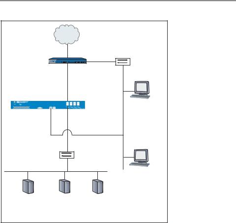
To use an IDP sensor as a passive intrusion detection system without prevention capabilities, deploy the sensor in passive sniffer mode to monitor and log network traffic. If the sensor is attached to a network switch, you must configure the switch to mirror all traffic to that port. The IDP sensor defaults to sniffer mode.
Active mode—The gateway (inline) mode is active. This mode takes full advantage of IDP attack prevention capabilities and multimethod detection mechanisms.
With inline modes, the sensor is directly involved in the packet flow. The sensor can stop attacks by dropping malicious packets before they reach their target.
Inline sensors are typically configured in transparent mode. For other inline modes, see “Advanced Configuration” on page 43.
NOTE: For IDP 8200 Release 4.2, only transparent mode is available.
One step in setting up IDP on your network is to decide on a deployment mode. Figure 1 and Figure 2 illustrate the possible deployment modes and their primary advantages and disadvantages.
Figure 1: Sniffer Mode (Passive)
Internet |
|
|
|
|
Hub or |
|
IP 2.2.2.1 |
Switch |
Firewall |
|
|
|
|
|
IP 1.1.1.1 |
|
|
Hub or |
Mirror or SPAN port, if a switch |
|
|
|
|
Switch |
|
|
|
|
Management |
|
|
Server |
|
straight-through cable |
IP 2.2.2.4 |
|
IDP Sensor |
eth2 |
|
|
User Interface |
|
MGT |
IP 2.2.2.5 |
|
port |
eth0 IP 2.2.2.7 |
Server1 |
Server2 |
Server3 |
IP 1.1.1.2 |
IP 1.1.1.3 |
IP 1.1.1.4 |
GW 1.1.1.1 |
GW 1.1.1.1 |
GW 1.1.1.1 |
|
Protected Machines |
|
Table 2 lists the advantages and the disadvantages of using the sensor in passive sniffer mode.
IDP Configuration Basics 3
IDP 75, 250, 800, and 8200 Installation Guide
Table 2: Advantages and Disadvantages of Sniffer Mode (Passive)
Advantages |
Disadvantages |
|
|
Seamlessly replaces the current intrusion |
Passively monitors with limited prevention |
detection |
only |
Causes minimal network changes |
Requires a hub or the Switched Port Analyser |
Does not create an additional |
(SPAN) port of a switch |
|
|
point-of-failure gateway |
|
Monitors and logs suspicious network activity
Figure 2: Transparent Mode (Inline Active)
|
Internet |
|
|
|
Firewall |
|
Hub or |
||
IP 2.2.2.1 |
Switch |
|||
|
|
|||
|
|
|
||
|
IP 1.1.1.1 |
|
|
|
|
eth2 |
|
|
|
|
No ip address |
|
||
IDP Sensor |
Forwarding Interface |
Management Server |
||
|
|
|
||
|
|
|
IP 2.2.2.4 |
|
eth0 IP 2.2.2.7 MGT |
eth3 |
|
|
|
Interface |
No IP address |
|
||
|
Forwarding Interface |
|
||
Hub or |
|
|
||
Switch |
|
|
||
|
|
|
User Interface |
|
|
|
|
IP 2.2.2.5 |
|
Server1 |
Server2 |
Server3 |
|
|
IP 1.1.1.2 |
IP 1.1.1.3 |
IP 1.1.1.4 |
|
|
GW 1.1.1.1 |
GW 1.1.1.1 |
GW 1.1.1.1 |
|
|
|
Protected Machines |
|
|
|
Table 3 lists the advantages and the disadvantages of using the sensor in active transparent (inline) mode.
4 IDP Configuration Basics
Chapter 1: Planning an Installation
Table 3: Advantages and Disadvantages of Transparent Mode (Inline Active)
Advantages |
Disadvantages |
|
|
Reliably responds to and prevents attacks |
Cannot connect IP networks with different |
Simple, transparent deployment |
address spaces |
|
|
Allows Layer 2 broadcasts |
|
No changes to routing tables or network |
|
equipment |
|
Forwards non-IP traffic |
|
|
|
NetScreen-Security Manager
Use NetScreen-Security Manager to administer the sensor. See the
NetScreen-Security Manager Administrator’s Guide to tailor your security policy to your network. See the IDP Concepts & Examples Guide to improve the performance and accuracy of your protection.
IDP Configuration Basics 5
IDP 75, 250, 800, and 8200 Installation Guide
6 IDP Configuration Basics
Chapter 2
Hardware Overview
This chapter provides detailed descriptions of the Juniper Networks IDP sensors and their components.
This chapter has the following sections:
IDP Sensors on page 7
Traffic Ports (Forwarding Interfaces) on page 10
Management Ports on page 13
Hard Drives and USB Ports on page 13
Power Supplies on page 13
IDP Sensor LEDs on page 14
IDP Sensors
This section provides an overview of the following IDP sensors:
IDP 75 Sensor on page 8
IDP 250 Sensor on page 8
IDP 800 Sensor on page 8
IDP 8200 Sensor on page 9
Each sensor contains a USB port you can use for reimaging the sensors.
CAUTION: Both the console serial port and the management network interface port use the same RJ-45 connector. Do not plug a network cable into the console serial port.
IDP Sensors 7
Loading...