


Operating Manual
Highly Dynamic Temperature Control Systems
with integrated programmer
LH 47
air cooled
LH 50
water cooled
Version: V45D-01 |
|
JULABO GmbH |
||
|
|
77960 Seelbach / Germany |
||
|
|
Tel. |
+49 |
(0) 7823 / 51-0 |
|
|
Fax |
+49 |
(0) 7823 / 24 91 |
|
|
info@julabo.de |
||
1.951.2790-V2 |
06/13 |
www.julabo.de |
||
19512790-V2.doc |
|
|
Print date: 29.07.13 |
|

Congratulations!
You have made an excellent choice.
JULABO thanks you for the trust you have placed in us.
This operating manual has been designed to help you gain an understanding of the operation and possible applications of our circulators. For optimal utilization of all functions, we recommend that you thoroughly study this manual prior to beginning operation.
Printed in Germany |
Changes without prior notification reserved |
Important: keep operating manual for future use
The JULABO Quality Management System
Temperature control devices for research and industry are developed, produced, and distributed according to the requirements of ISO 9001 and ISO 14001. Certificate Registration No. 01 100044846
Unpacking and inspecting
Unpack the unit and accessories and inspect them for possible transport damage. Damage should be reported to the responsible carrier, railway, or postal authority, and a damage report should be requested. These instructions must be followed fully for us to guarantee our full support of your claim for protecting against loss from concealed damage. The form required for filing such a claim will be provided by the carrier.
Lift the unit only with a crane (see pictures) using the lifting strands and the wooden crate . The recessed grips on the side are not suited for this purpose!
2

TABLE OF CONTENTS |
|
|
OPERATING MANUAL ....................................................................................................... |
5 |
|
1. |
INTENDED USE.................................................................................................... |
5 |
1.1. |
Description............................................................................................................. |
5 |
2. |
OPERATOR RESPONSIBILITY – SAFETY INSTRUCTIONS .............................. |
6 |
2.1. |
Disposal................................................................................................................. |
8 |
2.2. |
EC Conformity ....................................................................................................... |
8 |
2.3. |
Warranty conditions............................................................................................... |
9 |
2.4. |
Technical specifications....................................................................................... |
10 |
2.5. |
Cooling water connection .................................................................................... |
14 |
OPERATING INSTRUCTIONS ......................................................................................... |
15 |
|
3. |
SAFETY NOTES FOR THE USER...................................................................... |
15 |
3.1. |
Explanation of safety notes ................................................................................. |
15 |
3.2. |
Explanation of other notes................................................................................... |
15 |
3.3. |
Safety instructions ............................................................................................... |
15 |
4. |
OPERATING CONTROLS AND FUNCTIONAL ELEMENTS.............................. |
18 |
4.1. |
The Presto Plus principle with closed external system ........................................ |
24 |
5. |
PREPARATIONS ................................................................................................ |
25 |
5.1. |
Bath fluids............................................................................................................ |
25 |
5.2. |
Tubing.................................................................................................................. |
27 |
5.3. |
Installation ........................................................................................................... |
28 |
5.4. |
Connect the external system ............................................................................... |
28 |
5.5. |
Cooling water connection LH 50.......................................................................... |
30 |
5.6. |
Power connection ................................................................................................ |
31 |
5.7. |
Filling ................................................................................................................... |
31 |
5.7.1. |
Filling of external, closed systems................................................................ |
32 |
5.8. |
Degasifying.......................................................................................................... |
34 |
5.9. |
Draining ............................................................................................................... |
35 |
6. |
OPERATING PROCEDURES ............................................................................. |
36 |
6.1. |
Switching on / Selecting the language................................................................. |
36 |
7. |
MANUAL OPERATION........................................................................................ |
37 |
7.1. |
Start - Stop .......................................................................................................... |
37 |
7.2. |
Direct setting of the working temperature............................................................ |
38 |
7.3. |
Settings in the SET menu.................................................................................... |
38 |
7.3.1. |
Setting the working temperature................................................................... |
38 |
7.3.2. |
Warning functions......................................................................................... |
39 |
7.3.3. |
Setting the pump pressure stage.................................................................. |
40 |
7.4. |
Setting the safety temperature (with shutdown function)..................................... |
40 |
3

7.5. |
Internal / external control..................................................................................... |
42 |
8. |
MENU FUNCTIONS ............................................................................................ |
42 |
8.1. |
Configuration ....................................................................................................... |
44 |
8.2. |
Control parameters.............................................................................................. |
47 |
8.3. |
Start of a profile ................................................................................................... |
49 |
8.3.1. |
Interrupting a profile...................................................................................... |
51 |
8.4. |
Integrated programmer........................................................................................ |
52 |
8.5. |
Analog inputs/outputs.......................................................................................... |
55 |
8.6. |
Limits ................................................................................................................... |
58 |
8.7. |
Interface............................................................................................................... |
58 |
8.8. |
Sensors ............................................................................................................... |
59 |
8.9. |
Pump ................................................................................................................... |
60 |
9. |
TROUBLESHOOTING GUIDE / ERROR MESSAGES ....................................... |
61 |
10. |
ELECTRICAL CONNECTIONS........................................................................... |
63 |
11. |
REMOTE CONTROL........................................................................................... |
66 |
11.1. |
Setup for remote control ...................................................................................... |
66 |
11.2. |
Communication with a PC or a superordinated data system............................... |
67 |
11.3. |
List of commands ................................................................................................ |
68 |
11.4. |
Status messages / error messages ..................................................................... |
71 |
12. |
CLEANING THE UNIT......................................................................................... |
72 |
13. |
MAINTAINING / REPAIRING THE UNIT............................................................. |
75 |
4

Operating manual
1.Intended use
JULABO Temperature Systems have been designed for temperature application to specific fluids in a external closed system (oop circuit). The units feature pump connections for temperature control of external systems (loop circuit).
JULABO circulators are not suitable for direct temperature control of foods, semi-luxury foods and tobacco, or pharmaceutical and medical products. Direct temperature control means unprotected contact of the object with the bath medium (bath fluid).
1.1.Description
Besides the cooling unit, the main functional elements are the heater, circulation pump and control electronics. Via an external Pt100 control sensor, a self-optimizing, electronic proportional temperature control (PID characteristic) adapts the heat supplied to the thermal requirements of the external system.
The high pump capacity can be reduced by regulating the motor speed in five grades. It may thus be adapted to sensitive vessels.
LH47: The cooling unit may be cooled with air. LH50: The cooling unit may be cooled with water.
Setting is rapid and simple using the splash-proof keypads. The operating elements consist of the local operating board with a bright VFD-Info-Display, as well as the removable control module RD connected with a cable.
The microprocessor technology allows four temperature values to be stored and indicated on the DIALOG-DISPLAY (LCD) of the control module RD: working temperature, high and low temperature warning limits as well as pump pressure stage.
The digital RS232 / RS485 port permits modern process engineering without additional interface.
The excess temperature protection (safety temperature), a safety feature functioning independent of the regulator circuit, is adjusted and indicated via the VFD-Info-Display.
The integrated programmer allows programming of setpoint and time values for six temperature profiles.
The following analog sockets are available:
- The REG+E-PROG socket for setpoint selection via an external, analog programmer. At the same time, this socket provides three analog outputs for temperature recorders.
- The external Pt100 socket for external control. - The alarm output for an external signal.
- The stand-by input for external emergency switch-off.
5

Operator responsibility – Safety instructions
2.Operator responsibility – Safety instructions
The products of JULABO ensure safe operation when installed, operated, and maintained according to common safety regulations. This section explains the potential dangers that may arise when operating the circulator and also specifies the most important safety precautions to preclude these dangers as far as possible.
The operator is responsible for the qualification of the personnel operating the units.
The personnel operating the units should be regularly instructed about the dangers involved with their job activities as well as measures to avert these dangers.
Make sure all persons tasked with operating, installing, and maintaining the unit have read and understand the safety information and operating instructions.
When using hazardous materials or materials that could become hazardous, the circulator may be operated only by persons who are absolutely familiar with these materials and the unit. These persons must be fully aware of possible risks.
If you have any questions concerning the operation of your unit or the information in this manual, please contact us!
Contact: |
JULABO GmbH |
Tel. |
+49 (0) 7823 |
/ 51-0 |
info@julabo.de |
|
Eisenbahnstraße 45 |
Fax |
+49 (0) 7823 |
/ 24 91 |
www.julabo.de |
|
77960 Seelbach / Germany |
||||
|
|
|
|
|
Safety instructions for the operator:
Avoid strikes to the housing, vibrations, damage to the operating-element panel (keypad, display), and contamination.
Make sure the product is checked for proper condition regularly (depending on the conditions of use). Regularly check (at least every 2 years) the proper condition of the mandatory, warning, prohibition and safety labels.
Make sure that the mains power supply has low impedance to avoid any negative effects on the instruments being operated on the same mains.
This unit is designed for operation in a controlled electromagnetic environment. This means that transmitting devices (e.g., cellular phones) should not be used in the immediate vicinity.
Magnetic radiation may affect other devices with components sensitive to magnetic fields (e.g., monitors). We recommend maintaining a minimum distance of 1 m.
Permissible ambient temperature: max. 40 °C, min. 5 °C.
Permissible relative humidity: 50 % (40 °C).
Do not store the unit in an aggressive atmosphere. Protect the unit from contamination.
Do not expose the unit to sunlight.
Appropriate operation
Only qualified personnel is authorized to configure, install, maintain, or repair the unit.
Persons who operate the circulator must be trained in the particular tasks by qualified personnel. The summarized user guidance (short manual) and the specification table with information on individual parameters are sufficient for this.
6

Use
The bath can be filled with flammable materials. Fire hazard!
There might be chemical dangers depending on the bath medium used.
Observe all warnings for the used materials (bath fluids) and the respective instructions (safety data sheets).
Insufficient ventilation may result in the formation of explosive mixtures. Only use the unit in well ventilated areas.
Only use recommended materials (bath fluids). Do not use poisonous, vitriolic or corrosive bath fluids..
When using hazardous materials or materials that could become hazardous, the operator must affix the enclosed safety labels (1 + 2) to the front of the unit so they are highly visible:
1 |
Warning label W00: Colors: yellow, black |
|
|
Danger area. Attention! Observe instructions. |
|
|
(operating manual, safety data sheet) |
|
|
|
|
2 |
Mandatory label M018: |
Colors: blue, white |
|
Carefully read the user information prior to beginning operation. |
|
or |
Scope: EU |
|
|
|
|
2 |
Semi S1-0701 Table A1-2 #9 |
|
|
Carefully read the user information prior to beginning operation. |
|
|
Scope: USA, NAFTA |
|
|
|
|
Particular care and attention is necessary because of the wide operating range.
There are thermal dangers: Burn, scald, hot steam, hot parts and surfaces that can be touched. Warning label W26: Colors: yellow, black
Hot surface warning.
(The label is put on by JULABO)
Observe the instructions in the manuals for instruments of a different make that you connect to the circulator, particularly the corresponding safety instructions. Also observe the pin assignment of plugs and technical specifications of the products.
7

Operator responsibility – Safety instructions
2.1.Disposal
The product may be used with oil as bath fluid. These oils fully or partially consist of mineral oil or synthetic oil. For disposal, follow the instructions in the material safety data sheets.
This unit contains the refrigerants R-404A and R-23, which at this time are not considered harmful to the ozone layer. However, over the long operating period of the unit, disposal rules may change. Therefore, only qualified personnel should handle the disposal.
Valid in EU countries
See the current official journal of the European Union – WEEE directive. Directive of the European Parliament and of the Council on waste electrical and electronic equipment (WEEE).
This directive requires electrical and electronic equipment marked with a crossedout trash can to be disposed of separately in an environmentally friendly manner. Contact an authorized waste management company in your country.
Disposal with household waste (unsorted waste) or similar collections of municipal waste is not permitted!
2.2.EC Conformity
The products described in the operating instructions conform to the requirements of the following European guidelines:
Directive of the European Parliament and of the Council on the approximation of the laws of the Member States relating to machinery.
Low voltage regulations with respect to legal harmonization of the member countries concerning electric devices for use within certain voltage limits.
EMC guideline with respect to legal harmonization of the member countries concerning electromagnetic compatibility.
JULABO GmbH
Eisenbahnstr. 45
77960 Seelbach / Germany
8

2.3.Warranty conditions
JULABO GmbH warrants its products against defects in material or in workmanship, when used under appropriate conditions and in accordance with appropriate operating instructions
for a period of ONE YEAR.
Extension of the warranty period – free of charge
With the ‘1PLUS warranty’ the user receives a free of charge extension to the warranty of up to 24 months, limited to a maximum of 10 000 working hours.
To apply for this extended warranty the user must register the unit on the JULABO web site www.julabo.de, indicating the serial no. The extended warranty will apply from the date of JULABO GmbH’s original invoice.
JULABO GmbH reserves the right to decide the validity of any warranty claim. In case of faults arising either due to faulty materials or workmanship, parts will be repaired or replaced free of charge, or a new replacement unit will be supplied.
Any other compensation claims are excluded from this guarantee.
9

Operator responsibility – Safety instructions
2.4.Technical specifications
|
|
|
|
|
|
|
|
LH 47 |
|
|
|
|
|
|
|
LH 50 |
|
|
|
|
||
|
|
|
|
|
|
|
|
|
|
|
|
|
|
|
||||||||
|
|
|
|
|
|
|
|
|
|
|
|
|
|
|
|
|
|
|
|
|
|
|
Mains power connection |
V / |
|
360-440 V/3PNPE/50 Hz |
|
|
|
360-440 V/3PNPE/50 Hz |
|||||||||||||||
|
|
|
|
400 V/3P/50 Hz |
Hz |
|
|
|
|
|
|
|
|
|
|
|
|
|
|
|
|
|
Current input |
(at 230 V) |
|
A |
|
12 |
|
|
|
|
|
|
|
|
20 |
|
|
|
|
|
|||
|
|
|
|
|
|
|
|
|
|
|
|
|
|
|||||||||
Working temperature range |
|
°C |
|
-47 ... 250 |
|
|
|
|
|
|
|
-50 ... 250 |
|
|
|
|||||||
Temperature stability |
K |
±0.01 ... ±0.05 |
|
|
±0.01 ... ±0.05 |
|
|
|||||||||||||||
|
|
|
|
|
|
|
|
|
|
|
|
|
|
|||||||||
Cooling capacity |
°C |
200 100// 20 |
|
0 -20 -40 |
200 // |
20 |
0 |
-20 |
-40 |
|
||||||||||||
pump pressure stage 1 |
kW |
3.7 |
3.1 // 3.07 |
2.0 |
0.99 |
0.27 |
5.5 // |
7.3 |
4.6 |
2.3 |
0.45 |
|
||||||||||
pump pressure stage 5 |
kW |
3.5 |
3.0 // 2.9 |
1.9 |
0.90 |
0.07 |
5.5 // |
7.2 |
5.1 |
2.3 |
0.19 |
|
||||||||||
(bath liquid: Thermal / Ethanol) |
|
|
|
|
|
|
|
|
|
|
|
|
|
|
|
|
|
|||||
Cooling compressor |
|
1-stage |
|
|
|
|
|
|
|
1-stage |
|
|
|
|
||||||||
|
|
|
|
|
|
|
|
air-cooled |
|
|
|
|
|
|
|
water-cooled |
|
|
|
|||
Refrigerant |
|
|
|
|
R404A |
|
|
|
|
|
|
|
R404A |
|
|
|
|
|||||
Cooling water : Flow rate |
l/h |
----- |
|
|
|
|
|
390 |
|
|
|
|
|
|||||||||
at 20 °C inlet temperature |
|
|
|
|
|
|
|
|
|
|
|
|
|
|
|
|
|
|||||
Heater capacity |
|
|
kW |
|
1.8 |
|
|
|
|
|
|
|
|
6.0 |
|
|
|
|
|
|||
|
|
|
|
|
|
|
|
|
|
|
|
|
|
|
|
|
|
|
|
|
|
|
|
|
|
|
|
|
|
|
|
|
|
|
|
|
|
|
|
|
|||||
Pressure pump, adjustable |
grade |
1 |
2 |
3 |
|
4 |
5 |
|
|
|
|
|
|
|
|
|
||||||
pressure min ... max. at 0 liter |
bar |
0.5 |
0.7 |
1.1 |
1.3 |
1.7 |
|
|
|
|
|
|
|
|
|
|||||||
discharge, max. at 0 bar |
l/min |
16 |
19 |
23 |
26 |
30 |
|
|
|
|
|
|
|
|
|
|||||||
|
|
|
|
|
|
|
|
|
|
|
|
|
|
|
|
|
||||||
Pressure pump, adjustable |
grade |
|
|
|
|
|
|
|
1 |
2 |
3 |
|
4 |
5 |
||||||||
pressure min ... max. at 0 liter |
bar |
|
|
|
|
|
|
|
0.7 |
0.9 |
1.4 |
1.8 |
2.3 |
|||||||||
discharge, max. at 0 bar |
l/min |
|
|
|
|
|
|
|
17 19 24 27 31 |
|||||||||||||
|
|
|
|
|
|
|
|
Viscosity, max. 50 mm²/s (50 cSt) |
|
|
|
|
|
|||||||||
|
|
|
|
|
|
|
|
|
|
|
|
|
|
|
||||||||
Noise level, 1 m distance |
|
dBA |
|
72 |
|
|
|
|
|
|
----- |
|
|
|
|
|
||||||
Ambient temperature |
°C |
5 ... 40 |
|
|
|
|
5 ... 40 |
|
|
|
|
|||||||||||
|
|
|
|
|
|
|
|
|
|
|
|
|
|
|
|
|||||||
Filling volume |
Heat exchanger |
|
liters |
2.5 |
|
|
|
|
|
|
10 |
|
|
|
|
|
||||||
|
|
|
|
Reservoir |
|
liters |
|
3.2 … 8.4 |
|
|
|
|
|
|
|
3.2 … 8.4 |
|
|
|
|||
Overall dimensions (WxDxH) |
cm |
|
40x55x127 |
|
|
|
|
|
|
|
40x55x127 |
|
|
|
||||||||
|
|
|
|
|
|
|
|
|
|
|
|
|
|
|
|
|
||||||
Weight |
|
|
kg |
|
150 |
|
|
|
|
|
|
182 |
|
|
|
|
|
|||||
All measurements have been carried out at: rated voltage and frequency |
|
|
|
|
|
|
|
|
|
|||||||||||||
ambient temperature: 20 °C |
Technical changes without prior notification reserved. |
|
||||||||||||||||||||
 Pump data in relation to fluids with a specific density of 1 kg/dm3
10
|
|
|
|
|
|
|
|
LH 47 |
|
|
|
|
|
LH 50 |
|
|
|
||
|
|
|
|
|
|
|
|
|
|
|
|
|
|
||||||
|
|
|
|
|
|
|
|
|
|
|
|
|
|
|
|
|
|
|
|
Mains power connection |
V / Hz |
|
207-253 V/3PPE/60 Hz |
|
207-253 V/3PPE/60 Hz |
||||||||||||||
|
|
|
|
230 V/3P/60 Hz |
|
|
|
|
|
|
|
|
|
|
|
|
|
|
|
Current input |
(at 230 V) |
|
A |
|
13 |
|
|
|
|
|
|
27 |
|
|
|
|
|||
|
|
|
|
|
|
|
|
|
|
|
|
||||||||
Working temperature range |
|
°C |
|
-47 ... 250 |
|
|
|
|
|
-50 ... 250 |
|
|
|
||||||
Temperature stability |
K |
±0.01 ... ±0.05 |
|
|
|
±0.01 ... ±0.05 |
|
|
|||||||||||
|
|
|
|
|
|
|
|
|
|
|
|
||||||||
Cooling capacity |
°C |
200 100// 20 |
0 |
-20 |
-40 |
200 // |
20 |
0 |
-20 |
-40 |
|||||||||
pump pressure stage 1 |
kW |
3.8 |
3.3 // 3.2 |
2.1 |
1.1 |
0.32 |
5.5 // |
7.3 |
4.9 |
2.6 |
0.5 |
||||||||
pump pressure stage 5 |
kW |
3.7 |
3.2 // 3.1 |
2.0 |
1.0 |
0.12 |
5.5 // |
7.2 |
4.6 |
2.1 |
0.4 |
||||||||
(bath liquid: Thermal / Ethanol) |
|
|
|
|
|
|
|
|
|
|
|
|
|
|
|||||
Cooling compressor |
|
1-stage |
|
|
|
|
|
1-stage |
|
|
|
||||||||
|
|
|
|
|
|
|
|
air-cooled |
|
|
|
|
|
water-cooled |
|
|
|||
Refrigerant |
|
|
|
|
R404A |
|
|
|
|
|
R404A |
|
|
|
|||||
Cooling water : Flow rate |
l/h |
----- |
|
|
|
|
|
330 |
|
|
|
|
|||||||
at 20 °C inlet temperature |
|
|
|
|
|
|
|
|
|
|
|
|
|
|
|||||
Heater capacity |
|
|
kW |
|
1.8 |
|
|
|
|
|
|
6.0 |
|
|
|
|
|||
|
|
|
|
|
|
|
|
|
|
|
|
|
|
|
|
|
|
|
|
|
|
|
|
|
|
|
|
|
|
|
|
|
|
|
|||||
Pressure pump, adjustable |
grade |
1 |
2 |
3 |
|
4 |
5 |
|
|
|
|
|
|
||||||
pressure min ... max. at 0 liter |
bar |
0.5 |
0.7 |
1.1 |
1.3 |
1.7 |
|
|
|
|
|
|
|||||||
discharge, max. at 0 bar |
l/min |
16 |
19 |
23 |
26 |
30 |
|
|
|
|
|
|
|||||||
|
|
|
|
|
|
|
|
|
|
|
|
|
|
||||||
Pressure pump, adjustable |
grade |
|
|
|
|
|
|
|
1 |
2 |
3 |
4 |
5 |
||||||
pressure min ... max. at 0 liter |
bar |
|
|
|
|
|
|
|
0.7 |
0.9 |
1.4 |
1.8 2.3 |
|||||||
discharge, max. at 0 bar |
l/min |
|
|
|
|
|
|
|
17 19 24 27 31 |
||||||||||
|
|
|
|
|
|
|
|
Viscosity, max. 50 mm²/s (50 cSt) |
|
|
|
|
|||||||
|
|
|
|
|
|
|
|
|
|
|
|
|
|||||||
Noise level, 1 m distance |
|
dBA |
|
72 |
|
|
|
|
|
----- |
|
|
|
|
|||||
Ambient temperature |
°C |
5 ... 40 |
|
|
|
|
5 ... 40 |
|
|
|
|||||||||
|
|
|
|
|
|
|
|
|
|
|
|
|
|
||||||
Filling volume |
Heat exchanger |
|
liters |
2.5 |
|
|
|
|
|
10 |
|
|
|
|
|||||
|
|
|
|
Reservoir |
|
liters |
|
3.2 … 8.4 |
|
|
|
|
|
3.2 … 8.4 |
|
|
|||
Overall dimensions (WxDxH) |
cm |
|
40x55x127 |
|
|
|
|
|
40x55x127 |
|
|
||||||||
|
|
|
|
|
|
|
|
|
|
|
|
|
|
|
|||||
Weight |
|
|
kg |
|
150 |
|
|
|
|
|
182 |
|
|
|
|
||||
All measurements have been carried out at: rated voltage and frequency |
|
|
|
|
|
|
|||||||||||||
ambient temperature: 20 °C |
Technical changes without prior notification reserved. |
|
|||||||||||||||||
 Pump data in relation to fluids with a specific density of 1 kg/dm3
11

Operator responsibility – Safety instructions
Temperature selection |
|
digital |
via Removable control module RD |
|
indication on DIALOG-Display (LCD) |
remote control via personal computer |
indication on monitor |
|
Temperature indication |
|
VFD-Info-Display |
|
|
DIALOG-DISPLAY (LCD) |
Resolution |
K |
0.01 from -9.99 °C to +249.99 °C |
Pump pressure display |
|
on VFD-Info-Display in five grades |
Liquid level display |
|
on VFD-Info-Display in five grades |
Absolute Temperature Calibration |
|
|
(ATC1) |
K |
±3 |
(ATC2) |
K |
±9 |
Temperature control |
|
ICC - Intelligent Cascade Control, self-optimizing |
|
|
Cascade, parameter can be called-in and modified |
Working temperature sensor |
|
Pt 100 |
Safety temperature sensor |
|
Pt 100 |
Electrical connections: |
|
Computer interface |
RS232 or RS485 |
Programmer input -100 °C to 400 °C = |
0 to 10 V or 0 to 20 mA or 4 to 20 mA |
Temperature recorder outputs |
0 to 10 V (0 V = -100 °C, 10 V = 400 °C) |
|
0 to 20 mA (0 mA = -100 °C, 20 mA = 400 °C) |
|
4 to 20 mA (4 mA = -100 °C, 20 mA = 400 °C) |
Stand-by input |
|
External alarm device |
24-0 V DC / max. 25 mA |
External measurement and control sensor |
Pt100, 4-lead technique |
Control connector (10) Output voltage: |
230 V / max. 0.1 A |
S a f e t y i n s t a l l a t i o n s a c c o r d i n g t o I E C 6 1 0 1 0 - 2 - 0 1 0 : |
|
Excess temperature protection >TANK< |
adjustable from 0 °C ... 320 °C |
Excess temperature protection >RES< |
adjustable from 0 °C ... 220 °C |
Low level protection |
float switch |
Liquid level display |
optical, 5-graded |
Classification according to DIN 12876-1 |
class III FL |
Supplementary safety installations |
|
High temperature warning function |
optical + audible (in intervals) |
Low temperature warning function |
optical + audible (in intervals) |
Supervision of the working sensor |
plausibility control |
Reciprocal sensor monitoring between |
|
working and safety sensors |
difference >50 K |
Alarm indication |
optical + audible (permanent) |
12

E n v i r o n m e n t a l c o n d i t i o n s a c c o r d i n g t o I E C 6 1 0 1 0 - 1 :
Use only indoor.
Altitude up to 2000 m - normal zero.
Ambient temperature: see Technical specifications
Air humidity:
Max. rel. humidity 80 % for temperatures up to +31 °C,
linear decrease down to 50 % relative humidity at a temperature of +40 °C
Max. mains fluctuations of ±10 % are permissible.
Overvoltage category II
Pollution degree 2
Caution:
The unit is not suitable for use in explosive atmosphere
Protection class according to IEC 60 529: IP31
The unit corresponds to Class I
Standards for interference resistance according to EN 61326-1
This unit is an ISM device classified in Group 1 (using high frequency for internal purposes) Class A (industrial and commercial range).
13

Operator responsibility – Safety instructions
2.5.Cooling water connection
Cooling water pressure (IN / OUT ) |
max. |
6 bar |
|
Difference pressure (IN - OUT ) |
|
3.5 to 6 bar |
|
Cooling water temperature |
|
|
<20 °C |
Notice: |
Cooling water circuit |
|
|
Risk of oil leaking from the refrigeration system (compressor) of the recirculating cooler into the cooling water in case of a fault in the cooling water circuit! Observe the laws and regulations of the water distribution company valid in the location where the unit is operated.
Notice:
Danger of corrosion of heat exchanger due to unsuitable quality of cooling water.
Due to its high content of lime, hard water is not suitable for cooling and causes scale in the heat exchanger.
Ferrous water or water containing ferrous particles will cause formation of rust even in heat exchangers made of stainless steel.
Chlorinated water will cause pitting corrosion in heat exchangers made of stainless steel.
Due to their corrosive characteristics, distilled water and deionized water are unsuitable and will cause corrosion of the bath.
Due to its corrosive characteristics, sea water is not suitable.
Due to its microbiological (bacterial) components, which settle in the heat exchanger, untreated and unpurified river water and water from cooling towers is unsuitable.
Avoid particulate matter in cooling water.
Avoid putrid water.
Recommended quality of cooling water:
pH |
7.5 to 9.0 |
Sulfate [SO4 2- ] |
< 100 ppm |
Hydrocarbonate [HCO 3-]/sulfate [SO4 2-] |
> 1 ppm |
Hardness [Ca 2+, Mg 2+]/[HCO 3-] |
> 0.5 dH |
Alkalinity |
60 ppm < [HCO 3-] < 300 ppm |
Conductivity |
< 500 μS/cm |
Chloride (Cl -) |
< 50 ppm |
Phosphate (PO4 3-) |
< 2 ppm |
Ammonia (NH3) |
< 0.5 ppm |
Free chlorine |
< 0.5 ppm |
Trivalent iron ions (Fe 3+) |
< 0.5 ppm |
Manganese ions (Mn 2+) |
< 0.05 ppm |
Carbon dioxide (CO2) |
< 10 ppm |
Hydrogen sulfide (H2S) |
< 50 ppm |
Content of oxygen |
< 0.1 ppm |
Algae growth |
impermissible |
Suspended solids |
impermissible |
14

Operating instructions
3.Safety notes for the user
3.1.Explanation of safety notes
In addition to the safety warnings listed above, warnings are posted throughout the manual. These warnings are designated by an exclamation mark inside an equilateral triangle. “Warning of a dangerous situation (Attention! Please follow the documentation).”
The danger is classified using a signal word. Read and follow these important instructions.
Warning:
Describes a possibly highly dangerous situation. If these instructions are not followed, serious injury and danger to life could result.
Caution:
Describes a possibly dangerous situation. If this is not avoided, slight or minor injuries could result. A warning of possible property damage may also be contained in the text.
Notice:
Describes a possibly harmful situation. If this is not avoided, the product or anything in its surroundings can be damaged.
3.2.Explanation of other notes
Note!
Draws attention to something special.
Important!
Indicates usage tips and other useful information.
3.3.Safety instructions
Follow the safety recommendations to prevent damage to persons or property. Further, the valid safety instructions for working places must be followed.
Only connect the unit to a power socket with earthing contact (PE – protective earth)!
The power supply plug serves as safe disconnecting device from the line and must be always freely accessible.
Place the instrument on an even surface on a pad made of non-inflammable material.
Do not stay in the area below the unit.
Make sure you read and understand all instructions and safety precautions listed in this manual before installing or operating your unit.
Set the safety temperature.
Never operate the unit without bath fluid in the bath.
15

Safety notes for the user
Pay attention to the thermal expansion of bath oil during heating to avoid overflowing of the fluid.
Prevent water from penetrating into the hot bath oil.
Do not drain the bath fluid while it is hot!
Check the temperature of the bath fluid prior to draining (by switching the unit on for a short moment for example).
Employ suitable connecting tubing.
Avoid sharp bends in the tubing, and maintain a sufficient distance from surrounding walls.
Make sure that the tubing is securely attached.
Regularly check the tubing for material defects (e.g. for cracks).
Never operate damaged or leaking equipment.
Always turn off the unit and disconnect the mains cable from the power source before performing any service or maintenance procedures, or before moving the unit.
Always turn off the unit and disconnect the mains cable from the power source before cleaning the unit.
Always empty the bath before moving the unit.
Transport the unit with care.
Sudden jolts or drops may cause damages in the interior of the unit.
Observe all warning labels.
Never remove warning labels.
Never operate equipment with damaged mains power cables.
Repairs are to be carried out only by qualified service personnel.
Some parts of the bath cover and the pump connections may become extremely warm during continuous operation. Therefore, exercise particular caution when touching these parts.
Caution:
The temperature controlling i.e. of fluids in a reactor constitutes normal temperature system practice.
We do not know which substances are contained within these vessels. Many substances are:
inflammable, easily ignited or explosive
hazardous to health
environmentally unsafe
i.e.: dangerous
The user alone is responsible for the handling of these substances!
16

The following questions shall help to recognize possible dangers and to reduce the risks to a minimum.
Are all tubes and electrical cables connected and installed? Note:
sharp edges, hot surfaces in operation, moving machine parts, etc.
Do dangerous steams or gases arise when heating? Is an exhaust needed when working?
What to do when a dangerous substance was spilled on or in the unit? Before starting to work, obtain information concerning the substance and determine the method of decontamination.
Caution: |
Escape of vapors / gas |
The necessity of degassing requires that a closed system is not entirely sealed. Especially at increased working temperatures vapor / gas may escape.
Ensure sufficient ventilation at the place of installation!
Notice:
When you have finished the application, it is recommended to keep on circulating the liquid in the bath or the external system for some time. Simultaneously set the working temperature to +20 °C to allow the temperature in the system to decrease slowly.
Thus fractional over-heating of the bath liquid is prevented.
Notice:
Please check the safety device from time to time.
Excess temperature protection according to IEC 61010-2-010
With a screw driver turn back the adjustable excess temperature protection until the shut-down point (actual temperature).
Low level protection
To check the function of the float of this unit it cannot be operated manually. The 5-graded level display should therefore be observed whenever refilling. If the bath liquid thickens or cracks, the instrument should be cleaned and checked by qualified personnel.
17

Operating controls and functional elements
4.Operating controls and functional elements
Front view |
LH47 |
LH50 |
air-cooled |
water-cooled |
18
1
2
3
4
5
6
Mains power switch, illuminated
Local operating board
Socket board - description see page 20
Removable control module RD
Filling funnel (hinged)
|
Motor protection circuit breaker for compressor motor |
1 |
0
2 Mains circuit breakers (resettable) 10 A for the pump-motor 4 Mains circuit breakers (resettable) 16 A
7 |
Venting grid, removable |
|
|
|
8 |
Drain with drain port |
|
|
|
2 |
Local operating board |
|
|
|
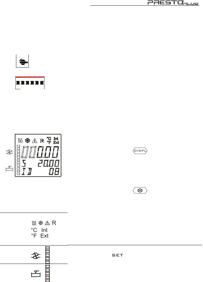
2.1 |
VFD-Info-Display |
|
|
|
|
Header: Control indicators see section 2.2 |
|
||
|
Line 1: |
Actual value |
Int or Ext |
|
|
|
To swap, press the key |
(see below) |
|
|
Line 2: |
Working temp. setpoint, constantly S xxx.xx |
||
|
or |
indication of the safety temperature (TANK) |
||
|
Line 3: |
Miscellaneous values |
|
|
|
|
To swap, press the key |
(see below) |
|
|
or |
indication of the safety temperature (RES) |
||
2.2 |
Control indicators in the header: |
|
||
|
Heating / Cooling / Alarm / Remote control |
|||
|
Temperature indication Internal or External actual value |
|||
|
Temperature indication in °C or °F |
|
||
|
Display for the adjusted pump pressure stage (five grades), |
|||
|
adjustable via the key . |
|
|
|
Liquid level display (five grades) for the reservoir.
19

Operating controls and functional elements
2.3
2.4 |
Int |
2.5
2.6
2.7
Key to swap line 3 on the VFD
ID |
xx |
Identification no. of control module RD |
L |
xx |
Capacity in % |
E xxx.xx or I xxx.xx Actual value (external or internal)
P x.xx |
Pump pressure in bar |
Key to swap line 1 on the VFD
Actual value Int or Ext alternating with line 3
Key to indicate the safety temperature on the VFD
Line 2: TANK - Safety temperature in internal bath Line 3: RES - Safety temperature in internal reservoir
Adjustable excess temperature protection (safety temperature) Used for setting the safety temperature in the internal bath, called "TANK" on the display
Adjustable safety temperature.
Used for setting the safety temperature in the internal reservoir, called "RES" on the display
2.8
3 |
Socket board |
3.1 |
|
REG+E-PROG
3.2
STAND-BY
3.3
ALARM
3.4
EXT. Pt100
3.5

 SERIAL
3.6
RD
Key for automatic filling and air purge of the unit as well as the connected external system.
Programmer input and temperature recorder output
Stand-by input (for external emergency switch-off)
Alarm output (for external alarm signal)
Connector for external measurement and control sensor
Interface RS232/RS485
Connector: control cable of control module RD
20
4
4.0
4.1
4.2
4.3
4.4
4.5
4.6
4.7
4.8
4.9
Control module RD
Setp: 120.00°C
IntAct 21.00°C
ExtAct: 20.00°C
Control: Intern
 >Setp.: 120.00°C
 Overt.:255.00°C Subtmp:-55.00°C St.Pump: 2
 >Configuration
  Control param. Profile Start Int. Programmer
DIALOG-DISPLAY (LCD) |
Standard indication |
|
Line 1: |
Setpoint |
in °C |
Line 2: |
Internal actual value |
in °C |
Line 3: |
External actual value |
in °C |
Line 4: |
Control type: internal / external control |
|
|
Indicating messages (e. g. warnings) |
|
Start / stop key
To switch the circulation pump, heating element and cooling unit.
SET Menu Key - Indicating and setting setpoint values
Set the following values: |
Setp.: |
|
in Line 1: |
the working temperature |
|
Line 2: |
the high temperature limit |
Overt.: |
Line 3: |
the low temperature limit |
Subtmp: |
Line 4: |
the pump pressure stage |
St.Pump: |
Control type: internal / external control
To swap, the unit has to be in the STOP MODE. Indicated in line 4 on the DIALOG-DISPLAY (LCD)
MENU key - for selecting the menu functions (Menu see page 42)
Cursor keys - Select menu items
P-key |
Selecting parameters |
||
Escape key |
1) |
Cancel entries |
|
|
|
2) |
Return to a higher menu level |
Enter key |
|
1) |
Store value / parameter |
|
|
2) |
Next lower menu level |
Numeric keypad: numerals 0 to 9; minus / decimal point
....
21
Operating controls and functional elements
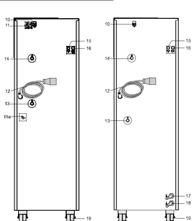
Rear
22

10 |
|
|
|
|
|
|
Control connector |
|
|
|
|
|
|
|
230 V / max. 0.1 A |
|
|
|
|
|
|
||
|
|
|
|
|
|
|
|
|
|
|
|
|
|
|
|
|
|
|
|
|
|
|
|
|
|
|
|
|
|
|
|
11 |
Si1 |
Si3 |
4 Mains circuit breakers (resettable) 16 A |
|
|||
|
16 |
16 |
|
|
A |
A |
F1 and F3 Compressor |
|
M |
M |
|
|
P |
P |
F2 and F4 Heater, Pump |
|
A |
A |
|
|
16 |
16 |
|
|
M |
M |
|
|
P |
P |
|
|
Si2 |
Si4 |
|
11a |
|
1 |
|
|
0 |
|
|
12
13 + 14
15
Motor protection circuit breaker for compressor motor
Mains power cable with plug
Pump connectors |
Return |
Feed |
M16x1 |
Overflow connector |
M16x1 |
|
|
16 |
|
|
Connector for expansion vessel |
M16x1 |
|
|
|||||
|
|
|
|
|
|
17 + 18 |
|
|
Cooling water connectors LH41 |
G3/4" external thread |
|
|
|
|
IN - inlet |
OUT - outlet |
|
|
|
|
Castor without brake (at the back) |
|
|
19 |
|
|
|
||
19a |
|
|
Castor with brake (at the front) |
|
|
23
 Loading...