


 Loading...
English
OPERATING MANUAL
Ultra-Low
Refrigerated Circulator
F81-HL
FP89-HL
F95-SL
FW95-SL
JULABO USA, Inc.
884 Marcon Boulevard
Allentown, PA 18109
Phone: +1(610) 231-0250
Fax: +1(610) 231-0260
info.us@ julabo.com
www.julabo.com
19532814-V5.doc |
10.11.17 |
Congratulations!
You have made an excellent choice.
JULABO thanks you for the trust you have placed in us.
This operating manual has been designed to help you gain an understanding of the operation and possible applications of our circulators. For optimal utilization of all functions, we recommend that you thoroughly study this manual prior to beginning operation.
The JULABO Quality Management System
Temperature control devices for research and industry are developed, produced, and distributed according to the requirements of ISO 9001 and ISO 14001. Certificate Registration No. 01 100044846
Unpacking and inspecting
Unpack the circulator and accessories and inspect them for possible transport damage. Damage should be reported to the responsible carrier, railway, or postal authority, and a damage report should be requested. These instructions must be followed fully for us to guarantee our full support of your claim for protecting against loss from concealed damage. The form required for filing such a claim will be provided by the carrier.
Printed in Germany |
Changes without prior notification reserved |
Important: keep operation manual for future use
1.953.2814-V5 11/17
2

HL, SL
TABLE OF CONTENTS |
|
||
Operating manual................................................................................................................ |
5 |
||
1. |
Intended use................................................................................................................. |
5 |
|
1.1. |
Description............................................................................................................... |
5 |
|
2. |
Operator responsibility – Safety recommendations....................................................... |
6 |
|
2.1. |
Disposal ................................................................................................................... |
8 |
|
2.2. |
Technical specifications ........................................................................................... |
9 |
|
2.3. |
Cooling water connection ....................................................................................... |
13 |
|
Operating instructions ....................................................................................................... |
14 |
||
3. |
Safety notes for the user............................................................................................. |
14 |
|
3.1. Explanation of safety notes .................................................................................... |
14 |
||
3.2. Explanation of other notes...................................................................................... |
14 |
||
3.3. |
Safety recommendations........................................................................................ |
15 |
|
4. |
Operating controls and functional elements ................................................................ |
17 |
|
5. |
Preparations ............................................................................................................... |
21 |
|
5.1. |
Installation.............................................................................................................. |
21 |
|
5.2. |
Bath fluids .............................................................................................................. |
21 |
|
5.3. Temperature application to external systems ......................................................... |
23 |
||
|
5.3.1.Tubing ............................................................................................................... |
24 |
|
5.4. |
Filling / draining...................................................................................................... |
25 |
|
6. |
Operating procedures ................................................................................................. |
26 |
|
6.1. |
Power connection................................................................................................... |
26 |
|
6.2. Switching on / Selecting the language.................................................................... |
26 |
||
|
6.2.1.Switching on the circulator................................................................................. |
26 |
|
|
6.2.2.Switching on the cooling machine...................................................................... |
27 |
|
6.3. |
Start - Stop............................................................................................................. |
27 |
|
7. |
|
Setting of temperatures ................................................................................. |
28 |
8. |
|
Safety installations, warning functions........................................................... |
28 |
|
8.0.1.Early warning system, low level protection......................................................... |
32 |
|
9. |
|
Menu functions.............................................................................................. |
33 |
9.1. Start of a program .................................................................................................. |
35 |
||
|
9.1.1.Status at the end of a program .......................................................................... |
37 |
|
|
9.1.2.Indication after successful start.......................................................................... |
37 |
|
|
9.1.3.Editing after Start............................................................................................... |
38 |
|
|
9.1.4.Interrupting a program ....................................................................................... |
38 |
|
|
9.1.5.Interruption after a power failure ........................................................................ |
39 |
|
|
9.1.6.Termination of a program................................................................................... |
39 |
|
9.2. |
Program administration, creation............................................................................ |
40 |
|
9.3. Setting the pump pressure ..................................................................................... |
44 |
||
9.4. |
Configuration.......................................................................................................... |
45 |
|
|
9.4.1.Remote control via the serial interface............................................................... |
48 |
|
|
9.4.2.Keypad control or setpoint setting via the analog input ...................................... |
48 |
|
|
9.4.3.Autostart ............................................................................................................ |
49 |
|
3

|
9.4.4.Off-Mode ............................................................................................................ |
49 |
|
|
9.4.5.ActVar - actuating variable.................................................................................. |
50 |
|
|
9.4.6.Setting of clock and date .................................................................................... |
51 |
|
|
9.4.7.Language ........................................................................................................... |
51 |
|
|
9.4.8.Unit..................................................................................................................... |
51 |
|
|
9.4.9.Program type...................................................................................................... |
51 |
|
|
9.4.10. Reset............................................................................................................. |
51 |
|
9.5. |
Control .................................................................................................................... |
52 |
|
|
9.5.1. Control internal / external................................................................................... |
54 |
|
|
9.5.2.Selftuning ........................................................................................................... |
55 |
|
|
9.5.3.Dynamik intern ................................................................................................... |
55 |
|
|
9.5.4.CoSpeed - extern ............................................................................................... |
56 |
|
|
9.5.5.Control parameters – internal/external................................................................ |
56 |
|
9.6. |
Serial Interface........................................................................................................ |
58 |
|
9.7. ATC Absolute Temperature Calibration, 3-point calibration..................................... |
59 |
||
|
9.7.1.ATC Fühler - intern / extern ................................................................................ |
62 |
|
|
9.7.2.ATC Status - yes / no ......................................................................................... |
62 |
|
|
9.7.3.Type 1 -/ 2 -/ 3 point .......................................................................................... |
62 |
|
|
9.7.4.Example: 3-point calibration for internal control ................................................. |
63 |
|
9.8. |
Limits ...................................................................................................................... |
65 |
|
|
9.8.1.Limits for internal control and external control..................................................... |
66 |
|
|
9.8.2.Limits for external control.................................................................................... |
67 |
|
9.9. |
Analog inputs/outputs ............................................................................................. |
68 |
|
|
9.9.1.Control connector ............................................................................................... |
72 |
|
|
9.9.2.Outputs of the connector - REG+E-PROG.......................................................... |
73 |
|
|
9.9.3.Input of the connector - REG+E-PROG .............................................................. |
74 |
|
|
9.9.4.External Stand-by input ...................................................................................... |
76 |
|
|
9.9.5.Alarm-output....................................................................................................... |
77 |
|
10. Troubleshooting guide / Error messages ..................................................................... |
78 |
||
11. |
Electrical connections.................................................................................................. |
81 |
|
12. Remote control ............................................................................................................ |
84 |
||
12.1. Setup for remote control.......................................................................................... |
84 |
||
12.2. Communication with a PC or a superordinated data system ................................... |
84 |
||
12.3. List of commands.................................................................................................... |
85 |
||
12.4. Status messages .................................................................................................... |
88 |
||
12.5. Error messages....................................................................................................... |
88 |
||
13. JULABO Service – Online remote diagnosis ............................................................... |
90 |
||
14. |
Installation of electronic module with analog connectors ............................................. |
91 |
|
15. |
Cleaning / repairing the unit......................................................................................... |
91 |
|
16. WARRANTY PROVISIONS......................................................................................... |
93 |
||
4
HL, SL
Operating manual
1.Intended use
JULABO circulators have been designed to control the temperature of specific fluids in a bath tank. The units feature pump connections for temperature control of external systems (loop circuit).
JULABO circulators are not suitable for direct temperature control of foods, semiluxury foods and tobacco, or pharmaceutical and medical products.
Direct temperature control means unprotected contact of the object with the bath medium (bath fluid).
1.1.Description
ICC
TCF
ATC3
RS232
RS485
Pt100
SMART
PUMP
The circulators are operated via the splash-proof keypad. The implemented microprocessor technology allows to set and to store different values that can be indicated on the VFD COMFORT-DISPLAY and LCD DIALOG-DISPLAY. Three menu keys facilitate adjusting setpoints, warning and safety functions and menu functions.
The integrated programmer allows storing and running temperature and timedependent processes.
The control electronics including “ICC - Intelligent Cascade Control“ automatically adapts the heat supplied to the thermal requirements of the bath.
The TCF - Temperature Control Features allow the user to have access to all important temperature control parameters. This means: Full control on the control mode and the chance to manually adjust or adapt control to the specific application.
Absolute Temperature Calibration (ATC3) provides high temperature stability in the bath. With the 3-point calibration an offset is adjusted at three temperatures to ensure an accurate temperature pattern at the selected spot in the bath over the full temperature range.
Electrical connections:
The serial interface, switchable from RS232 to RS485, allows modern process technology without additional interface.
Connection for Pt100 external sensor for external temperature measurement and control.
Alarm output for external alarm message or control of JULABO refrigerating baths or solenoid valve (cooling water).
The electronic module (option) provides 3 further analog connections (alarm input, standby input, recorder output, programmer input).
The excess temperature protection conforming to IEC 61010-2-010 is a safety installation independent from the control circuit. This protection can be indicated and set on the LCD DIALOG-DISPLAY.
The early warning system for low level signals that bath fluid needs to be refilled before the low level protection conforming to IEC 61010-2-010 causes a complete shut-down of the main functional elements.
Intelligent pump system: The pump capacity (electronically adjustable via the motor speed) enables to adapt to varying conditions for internal and external temperature applications.
5

Operator responsibility – Safety recommendations
2.Operator responsibility – Safety recommendations
The products of JULABO ensure safe operation when installed, operated, and maintained according to common safety regulations. This section explains the potential dangers that may arise when operating the circulator and also specifies the most important safety precautions to preclude these dangers as far as possible.
The operator is responsible for the qualification of the personnel operating the units.
The personnel operating the units should be regularly instructed about the dangers involved with their job activities as well as measures to avert these dangers.
Make sure all persons tasked with operating, installing, and maintaining the unit have read and understand the safety information and operating instructions.
When using hazardous materials or materials that could become hazardous, the circulator may be operated only by persons who are absolutely familiar with these materials and the circulator. These persons must be fully aware of possible risks.
If you have any questions concerning the operation of your unit or the information in this manual, please contact us!
Contact |
JULABO USA, Inc. |
Phone: |
+1(610) 231-0250 |
|
884 Marcon Boulevard |
Fax: |
+1(610) 231-0260 |
|
Allentown, PA 18109 |
info.us@ julabo.com |
|
|
|
|
www.julabo.com |
Safety instructions for the operator:
You have received a product designed for industrial use. Nevertheless, avoid strikes to the housing, vibrations, damage to the operating-element panel (keypad, display), and contamination.
Make sure the product is checked for proper condition regularly (depending on the conditions of use). Regularly check (at least every 2 years) the proper condition of the mandatory, warning, prohibition and safety labels.
Make sure that the mains power supply has low impedance to avoid any negative effects on instruments being operated on the same mains.
This unit is designed for operation in a controlled electromagnetic environment. This means that transmitting devices (e.g., cellular phones) should not be used in the immediate vicinity. Magnetic radiation may affect other devices with components sensitive to magnetic fields
(e.g., monitors). We recommend maintaining a minimum distance of 1 m.
Permissible ambient temperature: max. 40 °C, min. 5 °C.
Permissible relative humidity: 50% (40 °C).
Do not store the unit in an aggressive atmosphere.
Protect the unit from contamination.
Do not expose the unit to sunlight.
Appropriate operation
Only qualified personnel is authorized to perform configuration, installation, maintenance and repairs of the circulator.
Routine operation can also be carried out by untrained personnel who should however be instructed by trained personnel.
6
HL, SL
Use:
The bath can be filled with flammable materials. Fire hazard!
There might be chemical dangers depending on the bath medium used.
Observe all warnings for the used materials (bath fluids) and the respective instructions (safety data sheets).
Insufficient ventilation may result in the formation of explosive mixtures. Only use the unit in well ventilated areas.
Only use recommended materials (bath fluids). Only use non-acid and non corroding materials.
When using hazardous materials or materials that could become hazardous, the operator must affix the enclosed safety labels to the front of the unit so they are highly visible:
If this unit is intended for use within the United States of America, all 3 warning labels must be affixed to the housing of the unit prior to use.
Directions for the positioning of the individual warning labels are enclosed with the warning labels included in the delivery. Warning labels must be easily visible to users.
1 |
Warning label W00: Colors: yellow, black |
|
|
Danger area. Attention! Observe instructions. |
|
|
(operating manual, safety data sheet) |
|
2 |
Mandatory label M018: |
Colors: blue, white |
Carefully read the user information prior to beginning operation.
Scope: EU
or
2 Semi S1-0701 Table A1-2 #9
Carefully read the user information prior to beginning operation.
Scope: USA, NAFTA
3 |
Warning label Proposition 65 |
Particular care and attention is necessary because of the wide operating range.
There are thermal dangers: Burn, scald, hot steam, hot parts and surfaces that can be touched.
Warning label W26: Colors: yellow, black
Hot surface warning.
(The label is put on by JULABO)
Observe the instructions in the manuals for instruments of a different make that you connect to the circulator, particularly the respective safety recommendations. Also observe the pin assignment of plugs and technical specifications of the products.
7
Operator responsibility – Safety recommendations
2.1.Disposal
The circulator contains a back-up battery that supplies voltage to memory chips when the unit is switched off. Do not dispose of the battery with household waste!
Depending on battery regulations in your country, you might be obliged to give back used or defect batteries to gathering places.
The product may be used with oil as bath fluid. These oils fully or partially consist of mineral oil or synthetic oil. For disposal, observe the instructions in the safety data sheets.
This unit contains refrigerants, which at this time are not considered harmful to the ozone layer. However, over the long operating period of the unit, disposal rules may change. Therefore, only qualified personnel should handle the disposal.
Contact an authorized waste management company in your country.
Disposal with household waste (unsorted waste) or similar collections of municipal waste is not permitted!
8

HL, SL
2.2.Technical specifications
|
Ultra-Low Refrigerated Circulator |
|
|
|
F81-HL |
|
|
|
|
|
|
|
|
|
|
|
|
|
|||
|
Working temperature range |
|
°C |
-81 ... 100 |
|
|
|
|
||
|
Temperature stability |
|
°C |
±0,02 |
|
|
|
|
|
|
|
|
|
|
|
|
|
|
|
|
|
|
Cooling capacity |
|
°C |
|
+20 |
0 |
-20 |
-40 |
-60 -80 |
|
|
|
|
|
|
|
|
|
|
|
|
|
Medium ethanol |
|
kW |
|
0.45 |
0.38 |
0.36 |
0.32 |
0.27 0.07 |
|
|
Cooling compressor |
|
|
|
2-stage |
|
|
|
|
|
|
Refrigerant |
|
|
|
R404A + R23 |
|
|
|
||
|
|
|
|
|
|
|
|
|
|
|
|
Overall dimensions |
(WxDxH) |
cm |
|
50x58x89 |
|
|
|
|
|
|
Bath opening |
(WxL) |
cm |
|
13x15 |
|
|
|
|
|
|
Bath depth |
|
cm |
16 |
|
|
|
|
|
|
|
Filling volume |
|
liters |
5 ... 6,5 |
|
|
|
|
||
|
Weight |
|
kg |
88 |
|
|
|
|
|
|
|
Ambient temperature |
|
°C |
5 ... 40 |
|
|
|
|
||
|
|
|
|
|
|
|
|
|
||
|
Mains power connection |
|
V / Hz |
230 / 50/60 |
|
|
|
|
||
|
Current draw |
(at 230 V) |
A |
16 |
|
|
|
|
|
|
|
Mains power connection |
|
V / Hz |
----- |
|
|
|
|
|
|
|
Current draw |
(at 230 V) |
A |
----- |
|
|
|
|
|
|
|
Ultra-Low Refrigerated Circulator |
|
|
|
FP89-HL |
|
|
|
|
|
|
|
|
|
|
|
|
|
|
|
|||
|
Working temperature range |
|
°C |
-90 ... 100 |
|
|
|
|
|
||
|
Temperature stability |
|
°C |
±0,02 |
|
|
|
|
|
|
|
|
|
|
|
|
|
|
|
|
|
|
|
|
Cooling capacity |
|
°C |
|
+20 |
0 |
-20 |
-40 |
-60 |
-80 |
|
|
|
|
|
|
|
|
|
|
|
|
|
|
Medium ethanol |
|
kW |
|
1.0 |
0.92 |
0.88 |
0.75 |
0.58 |
0.2 |
|
|
Cooling compressor |
|
|
|
2-stage |
|
|
|
|
|
|
|
Refrigerant |
|
|
|
R404A + R508b |
|
|
|
|
||
|
|
|
|
|
|
|
|
|
|
|
|
|
Overall dimensions |
(WxDxH) |
cm |
|
55x60x92 |
|
|
|
|
|
|
|
Bath opening |
(WxL) |
cm |
|
13x15 |
|
|
|
|
|
|
|
Bath depth |
|
cm |
16 |
|
|
|
|
|
|
|
|
Filling volume |
|
liters |
5,5 ... 8 |
|
|
|
|
|
||
|
Weight |
|
kg |
135 |
|
|
|
|
|
|
|
|
Ambient temperature |
|
°C |
5 ... 35 |
|
|
|
|
|
||
|
|
|
|
|
|
|
|
|
|
||
|
Mains power connection |
|
V / Hz |
230 / 50 |
|
|
|
|
|
||
|
Current draw |
(at 230 V) |
A |
16 |
|
|
|
|
|
|
|
|
Mains power connection |
|
V / Hz |
230 / 60 |
|
|
|
|
|
||
|
Current draw |
(at 230 V) |
A |
16 |
|
|
|
|
|
|
|
9

Operator responsibility – Safety recommendations
|
Ultra-Low Refrigerated Circulator |
|
|
|
F95-SL |
|
|
|
|
|
|
|
|
|
|
|
|||
|
Working temperature range |
|
°C |
-95 ... 0 |
|
|
|
||
|
Temperature stability |
|
°C |
±0,05 |
|
|
|
|
|
|
|
|
|
|
|
|
|
|
|
|
Cooling capacity |
|
°C |
0 |
-20 |
-40 |
-60 |
-80 |
|
|
Medium ethanol |
|
kW |
1.7 |
1.5 |
1.3 |
1.1 |
0.36 |
|
|
Cooling compressor |
|
|
|
2- stage |
|
|
|
|
|
Refrigerant |
|
|
|
R404A + R23 |
|
|
||
|
|
|
|
|
|
|
|
|
|
|
Overall dimensions |
(WxDxH) |
cm |
|
59x76x116 |
|
|
|
|
|
Bath opening |
(WxL) |
cm |
|
7 |
|
|
|
|
|
Bath depth |
|
cm |
----- |
|
|
|
|
|
|
Filling volume |
|
liters |
22 |
|
|
|
|
|
|
Weight |
|
kg |
201 |
|
|
|
|
|
|
Ambient temperature |
|
°C |
5 ... 40 |
|
|
|
||
|
|
|
|
|
|
|
|
|
|
|
Mains power connection |
|
V/ Hz |
|
400 / 50 / 3PNPE |
|
|
||
|
Current draw |
(at 400 V) |
A |
24 |
|
|
|
|
|
|
Mains power connection |
|
V/ Hz |
|
208-230 / 60 / 3PPE |
|
|||
|
Current draw |
(at 230 V) |
A |
28 |
|
|
|
|
|
|
Ultra-Low Refrigerated Circulator |
|
|
|
FW95-SL (wassergekühlt) |
|
||||
|
|
|
|
|
||||||
|
Working temperature range |
|
°C |
-95 ... 0 |
|
|
|
|
||
|
Temperature stability |
|
°C |
±0,05 |
|
|
|
|
|
|
|
|
|
|
|
|
|
|
|
|
|
|
Cooling capacity |
|
°C |
0 |
-20 |
-40 |
-60 |
-80 |
|
|
|
Medium ethanol |
|
kW |
1.7 |
1.5 |
1.3 |
1.1 |
0.36 |
|
|
|
Cooling compressor |
|
|
|
2- stage |
|
|
|
|
|
|
Refrigerant |
|
|
|
R404A + R23 |
|
|
|
||
|
|
|
|
|
|
|
|
|
|
|
|
Overall dimensions |
(WxDxH) |
cm |
|
59x76x116 |
|
|
|
|
|
|
Bath opening |
(WxL) |
cm |
|
7 |
|
|
|
|
|
|
Bath depth |
|
cm |
----- |
|
|
|
|
|
|
|
Filling volume |
|
liters |
22 |
|
|
|
|
|
|
|
Weight |
|
kg |
214 |
|
|
|
|
|
|
|
Ambient temperature |
|
°C |
5 ... 40 |
|
|
|
|
||
|
|
|
|
|
|
|
|
|
|
|
|
Mains power connection |
|
V/ Hz |
|
400 / 50 / 3PNPE |
|
|
|
||
|
Current draw |
(at 400 V) |
A |
24 |
|
|
|
|
|
|
|
Mains power connection |
|
V/ Hz |
|
208-230 / 60 / 3PPE |
|
|
|||
|
Current draw |
(at 230 V) |
A |
28 |
|
|
|
|
|
|
10
|
|
|
|
|
|
|
|
HL, SL |
|
|
|
|
|
|
|
|
|
|
|
|
|
|
|
|
|
HL |
|
SL |
|
Temperature selection |
|
|
|
|
digital |
|
|
|
|
via keypad |
|
|
|
|
indication on LCD DIALOG-DISPLAY (°C/°F) |
|
|||
remote control via PC |
|
|
|
indication on monitor |
|
|
|
||
Temperature indication |
|
|
|
|
VFD COMFORT-DISPLAY (°C/°F) |
|
|||
Resolution |
|
|
°C |
0.01 |
|
|
|
||
ATC3 |
|
INT / EXT |
°C |
|
±3 / ±9 |
|
|
|
|
Temperature control |
|
|
|
|
ICC - Intelligent Cascade Control |
|
|||
Heater wattage (at 230 V) |
|
|
|
|
|
|
|
||
Heater wattage (at 115 V) |
|
kW |
2.0 |
3.0 |
|
||||
Temperature selection |
|
|
kW |
|
1.0 |
|
----- |
|
|
|
|
|
|
|
|||||
Electronically adj. pump capacity |
stages |
|
1 ... 4 |
|
1 ... 4 |
|
|||
Flow rate |
|
at 0 bar |
l/min |
22 ... 26 |
22 ... 26 |
|
|||
Max. pressure |
|
at 0 liters |
bar |
|
0.7 |
|
0.7 |
|
|
Max. suction |
|
at 0 liters |
bar |
0.4 |
0.4 |
|
|||
|
|
|
|
|
|
|
|
|
|
Electrical connections: |
|
|
|
|
See page 12 |
|
|
|
|
|
|
|
|
|
|
|
|
|
|
Ambient temperature |
|
|
°C |
5 ... 40 |
5 ... 40 |
|
|||
|
|
|
|
|
|
|
|
|
|
Mains power connection |
|
|
V/ Hz |
208-230 / 50/60 |
208-230 / 50/60 |
|
|||
Current draw |
(at 208 V / 230 V) |
A |
|
8 / 9 |
|
12 / 13 |
|
||
Mains power connection |
|
|
V/ Hz |
100-115 / 50/60 |
----- |
|
|||
Current draw |
(at 100 V / 115 V) |
A |
9 / 10 |
----- |
|
||||
All measurements have been carried out at: rated voltage and frequency |
|
|
|
||||||
ambient temperature: 20 °C |
Technical changes without prior notification reserved. |
|
|||||||
11

Operator responsibility – Safety recommendations
Electrical connections: |
|
External alarm device |
24-0 V DC / max. 25 mA |
Computer interface RS232 or RS485 |
|
External Pt100 sensor |
|
Optional for HL, SL
(Order No. 8900100 Electronic module with analog connections) Programmer input -100 °C to 400 °C = 0 - 10 V or 0 - 20 mA or 4 - 20 mA Input for the signal of a flow meter or external manipulated variable
Temperature recorder outputs |
0 - 10 V (0 V = -100 °C, 10 V = 400 °C) |
|
0 - 20 mA (0 mA = -100 °C, 20 mA = 400 °C) |
|
4 - 20 mA (4 mA = -100 °C, 20 mA = 400 °C) |
Standby input |
for external emergency switch-off |
Alarm output |
for external alarm signal |
Safety installations according to IEC 61010-2-010: |
|
Excess temperature protection |
adjustable from 0 °C ... 320 °C |
Low liquid level protection |
float switch |
Classification according to DIN 12876-1 |
class III |
Supplementary safety installations |
|
Early warning system for low level |
float switch |
High temperature warning function |
optical + audible (in intervals) |
Low temperature warning function |
optical + audible (in intervals) |
Supervision of working sensor |
plausibility control |
Reciprocal sensor monitoring between |
|
working and safety sensors |
difference >35 K |
Alarm message |
optical + audible (permanent) |
Warning message |
optical + audible (in intervals) |
Environmental conditions according to IEC 61 010-1: |
|
Use indoors only. |
|
Altitude up to 2000 m - normal zero. |
|
Ambient temperature: see Technical specifications |
|
Humidity: |
|
Max. relative humidity 80% for temperatures up to +31 °C, |
|
linear decrease down to 50% relative humidity at a temperature of +40 °C |
|
Max. mains voltage fluctuations of ±10% are permissible. |
|
Protection class according to IEC 60 529 |
IP21 |
The unit corresponds to Class I |
|
Overvoltage category |
II |
Pollution degree |
2 |
Caution: |
|
The unit is not suitable for use in explosive environment
EMC requirements
The device is an ISM device of group 1 per CISPR 11 (uses HF for internal purposes) and is classified in class A (industrial and commercial sector).
Notice:
•Devices of class A are intended for the use in an industrial electromagnetic environment.
•When operating in other electromagnetic environments, their electromagnetic compatibility may be impacted.
12

HL, SL
2.3.Cooling water connection
Cooling water pressure (IN/OUT) |
max. |
6 bar |
|
Pressure difference (IN - OUT) |
|
|
3.5 to 6 bar |
Cooling water temperature |
|
|
< 20 °C |
Notice: |
Cooling water circuit |
|
|
Risk of oil leaking from the refrigeration system (compressor) of the recirculating cooler into the cooling water in case of a fault in the cooling water circuit!
Observe the laws and regulations of the water distribution company valid in the location where the unit is operated.
Notice:
Danger of corrosion of heat exchanger due to unsuitable quality of cooling water.
•Due to its high content of lime, hard water is not suitable for cooling and causes scale in the heat exchanger.
•Ferrous water or water containing ferrous particles will cause formation of rust even in heat exchangers made of stainless steel.
•Chlorinated water will cause pitting corrosion in heat exchangers made of stainless steel.
•Due to their corrosive characteristics, distilled water and deionized water are unsuitable and will cause corrosion of the bath.
•Due to its corrosive characteristics, sea water is not suitable.
•Due to its microbiological (bacterial) components, which settle in the heat exchanger, untreated and unpurified river water and water from cooling towers is unsuitable.
•Avoid particulate matter in cooling water.
•Avoid putrid water.
Recommended quality of cooling water:
pH |
7.5 to 9.0 |
Sulfate [SO4 2- ] |
< 100 ppm |
Hydrocarbonate [HCO 3-]/sulfate [SO4 2-] |
> 1 ppm |
Hardness [Ca 2+, Mg 2+]/[HCO 3-] |
> 0.5 °dH |
Alkalinity |
60 ppm < [HCO 3-] < 300 ppm |
Conductivity |
< 500 μS/cm |
Chloride (Cl -) |
< 50 ppm |
Phosphate (PO4 3-) |
< 2 ppm |
Ammonia (NH3) |
< 0.5 ppm |
Free chlorine |
< 0.5 ppm |
Trivalent iron ions (Fe 3+) |
< 0.5 ppm |
Manganese ions (Mn 2+) |
< 0.05 ppm |
Carbon dioxide (CO2) |
< 10 ppm |
Hydrogen sulfide (H2S) |
< 50 ppm |
Content of oxygen |
< 0.1 ppm |
Algae growth |
impermissible |
Suspended solids |
impermissible |
13
Operating instructions
Operating instructions
3.Safety notes for the user
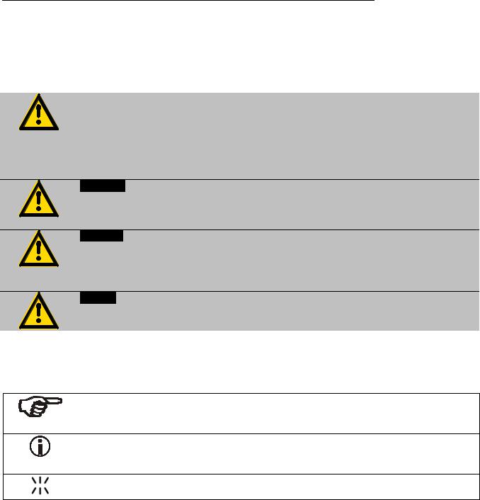
3.1.Explanation of safety notes
In addition to the safety warnings listed, warnings are posted throughout the operating manual. These warnings are designated by an exclamation mark inside an equilateral triangle. “Warning of a dangerous situation (Attention! Please follow the documentation).”
The danger is classified using a signal word.
Read and follow these important instructions for averting dangers.
Warning:
Describes a possibly highly dangerous situation. If these instructions are not followed, serious injury and danger to life could result.
Caution:
Describes a possibly dangerous situation. If this is not avoided, slight or minor injuries could result. A warning of possible property damage may also be contained in the text.
Notice:
Describes a possibly harmful situation. If this is not avoided, the product or anything in its surroundings can be damaged.
3.2.Explanation of other notes
Note!
Draws attention to something special.
Important!
Indicates usage tips and other useful information.
This icon is used in the operating instructions to indicate flashing values or parameters which have to be set or confirmed.
14

HL, SL
3.3.Safety recommendations
Follow the safety instructions to avoid personal injury and property damage. Also, the valid safety instructions for workplaces must be followed.
•Only connect the unit to a power socket with an earthing contact (PE – protective earth)!
•The power supply plug serves as a safe disconnecting device from the line and must always be easily accessible.
•Place the unit on an even surface on a base made of nonflammable material.
•Do not stay in the area below the unit.
•Make sure you read and understand all instructions and safety precautions listed in this manual before installing or operating your unit.
•Adjust excess-temperature safety device below the flash point of the bath fluid.
•Observe the limited working temperature range when using plastic bath tanks.
•Never operate the unit without bath fluid in the bath.
•Pay attention to the thermal expansion of bath oil during heating to avoid overflowing of the fluid.
•Prevent water from entering the hot bath oil.
•Do not drain the bath fluid while it is hot!
Check the temperature of the bath fluid prior to draining (e.g., by switching the unit on for a short moment).
•Use suitable connecting tubing.
•Avoid sharp bends in the tubing, and maintain a sufficient distance from surrounding walls.
•Make sure that the tubing is securely attached.
•Regularly check the tubing for material defects (e.g., for cracks).
•Never operate damaged or leaking units.
•Always turn off the unit and disconnect the mains cable from the power source before performing any service or maintenance procedures, or before moving the unit.
•Always turn off the unit and disconnect the mains cable from the power source before cleaning the unit.
•Always empty the bath before moving the unit.
•Transport the unit with care.
•Sudden jolts or drops may cause damage in the interior of the unit.
•Observe all warning labels.
•Never remove warning labels.
•Never operate units with damaged mains power cables.
•Repairs are to be carried out only by qualified service personnel.
Some parts of the bath tank and the pump connections may become extremely hot during continuous operation. Therefore, exercise particular caution when touching these parts.
15

Safety notes for the user
Caution:
The temperature controlling i.e. of fluids in a reactor constitutes normal circulator practice.
We do not know which substances are contained within these vessels. Many substances are:
•inflammable, easily ignited or explosive
•hazardous to health
•environmentally unsafe
i.e.: dangerous
The user alone is responsible for the handling of these substances!
The following questions shall help to recognize possible dangers and to reduce the risks to a minimum.
•Are all tubes and electrical cables connected and installed? Note:
sharp edges, hot surfaces in operation, moving machine parts, etc.
•Do dangerous steams or gases arise when heating? Is an exhaust needed when working?
•What to do when a dangerous substance was spilled on or in the unit? Before starting to work, obtain information concerning the substance and determine the method of decontamination.
Notice: Check the safety installations at least twice a year!
•Excess temperature protection according to IEC 61010-2-010.
With a screwdriver turn back the adjustable excess temperature protection until the shut-down point (actual temperature).
•Low level protection according to IEC 61010-2-010.
To check the function of the float, it can be manually lowered with a screwdriver for example.
WARNING
This product contains chemicals known to the state of California to cause cancer, birth defects or other reproductive harm.
16

HL, SL
4.Operating controls and functional elements
Front view |
Rear view |
1a
1b
2
|
|
|
|
|
|
|
|
|
|
|
|
|
|
Mains power switch, illuminated |
for circulator |
||
|
|
|
|
|
|
|
|
|
|
|
|
|
|
Mains power switch, illuminated |
for cooling machine |
||
|
|
|
|
|
|
|
|
|
|
|
|
|
|
VFD COMFORT-DISPLAY |
|
||
|
|
|
|
|
|
|
|
|
|
|
|
|
|
|
|||
|
|
|
|
|
|
|
|
|
|
|
|
|
|
|
|||
|
|
|
|
|
|
|
|
|
|
|
|
|
|
|
|||
|
|
|
|
|
|
|
|
|
|
|
|
|
|
|
|||
|
|
|
|
|
|
|
|
|
|
|
|
|
|
Header: Control indicators |
|
||
|
|
|
|
|
|
|
|
|
|
|
|
|
|
|
|||
|
|
|
|
|
|
|
|
|
|
|
|
|
|
|
|||
|
|
|
|
|
|
|
|
|
|
|
|
|
|
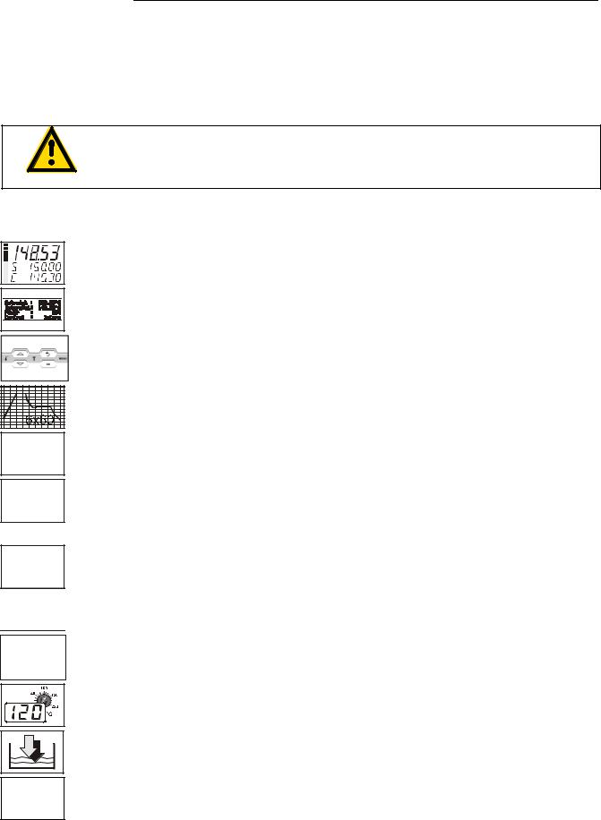
Line 1: |
Actual value |
|
internal or external |
|
|
|
|
|
|
|
|
|
|
|
|
|
|
|
|||
|
|
|
|
|
|
|
|
|
|
|
|
|
|
|
|||
|
|
|
|
|
|
|
|
|
|
|
|
|
|
|
The display is depending on the selected control mode in the |
||
|
|
|
|
|
|
|
|
|
|
|
|
|
|
|
|||
|
|
|
|
|
|
|
|
|
|
|
|
|
|
|
|||
|
|
|
|
|
|
|
|
|
|
|
|
|
|
|
menu > Control < (internal or external). |
||
|
|
|
|
|
|
|
|
|
|
|
|
|
|
|
|||
|
|
|
|
|
|
|
|
|
|
|
|
|
|
Line 2: |
Working temp. setpoint, constantly S xxx.xx |
||
|
|
|
|
|
|
|
|
|
|
|
|
|
|
Line 3: |
Actual value (E = external or I = internal) |
||
|
|
|
|
|
|
|
|
|
|
|
|
|
|
|
Alternating with the display in line 1 |
||
|
|
|
|
|
|
|
|
|
|
|
|
|
|
Use the keys |
to indicate further values in line 3 |
||
|
|
|
|
|
|
|
|
|
|
|
|
|
|
PI |
Capacity in % - with manipulated variable set to >control<* |
||
|
|
|
|
|
|
|
|
|
|
|
|
|
|
PS |
Capacity in % - with manipulated variable set to >serial<* or |
||
|
|
|
|
|
|
|
|
|
|
|
|
|
|
>eprog<* |
|
|
|
|
|
|
|
|
|
|
|
|
|
|
|
|
|
H |
Heater capacity in Watts |
|
|
|
|
|
|
|
|
|
|
|
|
|
|
|
|
U |
Mains voltage Volts |
|
|
17
Operating controls and functional elements
FFlow rate in liters/minute
(providing EPROG input set to >Flow rate<)
|
*refer to >MENU / CONFIGIGURATIO> page 35 |
|
2.1 |
Control indicators in the header: |
|
|
Heating / Cooling / Alarm / |
|
2.2 |
Remote control |
|
Control indicators in the header: |
|
|
|
Temperature indication Internal or External actual value |
|
|
Temperature indication in °C or °F |
|
2.3 |
Display for the adjusted pump pressure stage in the -OFF- mode. |
|
Display for the effective pump pressure stage (rotation speed) after start. |
||
|
Four stages, adjustable via the |
button, in the menu >PUMP<. |
3 |
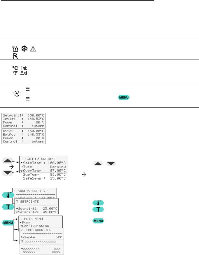
LCD DIALOG-DISPLAY |
|
Line 1: Setpoint and origin of setpoint programming (Key / RS232 or RS485 / ext. Pt100 / EProg)
Line 2: Actual value - internal or external,
identical to line 1 of the VFD-COMFORT-DISPLAY Line 3: Heating capacity in %.
Line 4: Control type: internal / external
Navigation aid in MENU - Window |
|
||
Keys |
/ |
: |
|
|
Selection of menu items / parameters |
||
- Setting in line 3: |
|
||
|
Actual value / parameter |
|
|
|
|
||
Orientation aid in MENU - Window |
|
||
Line 1 - name with allocation to key |
|
||
|
Safety values |
|
|
|
T – Setpoint |
|
|
|
1 |
Main menu |
Level 1 |
|
2 |
Submenu |
Level 2 |
|
|
Example: CONFIGURATION |
|
|
3 |
Submenu |
Level 3 |
18
|
|
|
|
HL, SL |
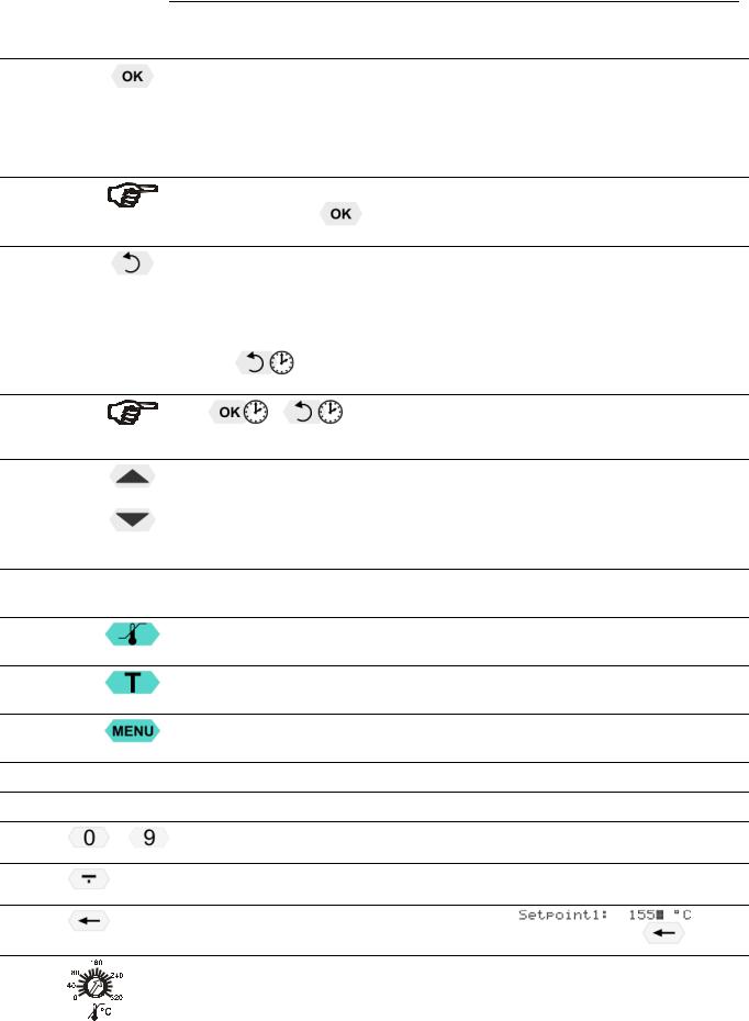
4 |
Keypad 1 |
Navigation keys |
|
|
4.1 |
|
1. Key: >OK< |
Start / Stop (pump / heater ) |
|
|
|
2. >OK< in the menu |
Menu item / select submenu for setting |
|
|
|
Save set value |
||
|
|
Save selected parameter |
||
|
|
A beep signals the end of setting |
||
|
|
After the actions Start, Stop and change from VFD Display to standard |
||
|
|
display the key |
|
is locked for a short time. |
|
|
The above graph “front side” shows an example for standard display. |
||
4.2 |
|
1. Key: >Return< |
|
Stop (pump / heater) |
|
|
|
|
Special display on VFD Display leave line 3. |
2. >Return< in the menu one menu level down
Correction function for parameters or values (prior to OK) immediately back to standard display
|
|
- |
icon for „keep key pressed down“. |
4.3 |
|
1. Key: |
>Up / Down <temperature – increase/decrease setpoint |
|
|
|
Push key quickly for single steps, |
|
|
|
Keep key pressed for fast change. |
|
|
2. >Up/Down< in the menu selection of menu items / parameters |
|
|
|
Menu keys |
|
4.4 |
|
Key: start the menu > warning and safety values< |
|
4.5 |
|
Key: start the menu >temperature setpoints< |
|
4.6 |
|
Key: display of MENU structure |
|
5 |
Keypad 2 |
|
|
|
.. |
Numeric keypad: numerals 0 to 9 |
|
|
|
|
|
|
|
minus / decimal point |
|
|
|
Backspace key |
|
|
|
on LCD DIALOG-DISPLAY. |
|
6 |
|
Adjustable excess temperature protection according to IEC 61010-2-010 |
|
19
Operating controls and functional elements
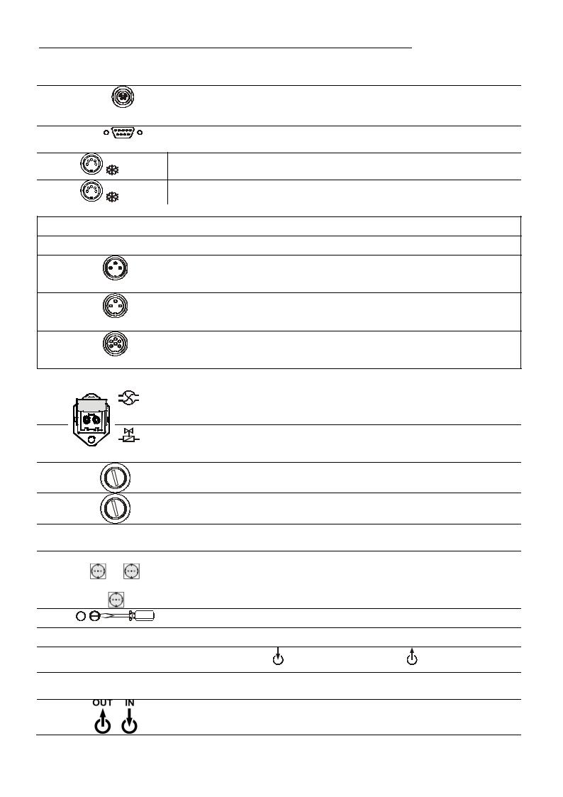
Rear view
7 |
Socket for external measurement and control sensor |
ext Pt100 |
or external setpoint programming |
|
|
8 |
Interface RS232 / RS485: remote control via personal computer |
SERIAL |
|
9 |
Control cable of JULABO refrigerated circulator |
9a |
Socket: output for alarm messages |
9b |
Socket: |
Option: Electronic module |
Order No. 8 900 100 |
The circulator automatically recognizes the connected electronic module.
10 |
|
Alarm output (for external alarm signal) |
|
11 |
ALARM |
|
|
|
Standby input (for external emergency switch-off) |
||
12 |
STAND-BY |
|
|
|
Programmer input and temperature recorder output |
||
|
REG+E-PROG |
|
|
13 |
|
Connector for supplementary pump or solenoid valve |
|
|
|
230 V / max. 1.25 A |
|
|
|
No control voltage in the -OFF- condition |
|
14 |
|
Connector solenoid valve |
|
|
|
1. No control voltage in the -OFF- condition |
|
15 |
|
2. Configurable |
(Refer to page 68) |
|
Fuses (for connectors 13, 14), T1.25A |
||
16 |
|
Mains fuses, T16A |
|
17a |
|
Mains power cable with plug for circulator |
|
17b |
|
Mains power cable with plug cooling machine |
|
18 |
F95, FW95 |
1 Built-in mains outlet for connection of circulator 230 V/16 A |
|
|
|
1 Built-in mains outlet 230 V/6 A |
|
18 |
F81 |
1 Built-in mains outlet for connection of circulator 230 V/10 A |
|
|
|
(not on FP89) |
|
19
20
21
22
23
24
Drain screw with drain connection
Venting grid, removable
Pump connections |
suction pump |
pressure pump |
Castor with brake (at the front)
Castor without brake (at the back)
Kühlwasseranschlüsse für FW Kältethermostate
20
5.Preparations
5.1.Installation
G½"
HL, SL
•Place the unit on an even surface on a pad made of non-flammable material. Using the castors move the unit to the intended location. For better stability, apply the holding breaks on the front casters.
•Cooling machine, pump motor and electronics produce intrinsic heat that is dissipated via the venting openings! Never cover these openings!
•Keep at least 20 cm of open space on the front and rear venting grids.
•The place of installation should be large enough and provide sufficient air ventilation to ensure the room does not warm up excessively because of the heat the instrument rejects to the environment. (Max. permissible ambient temperature: 40 °C).
For a fault (leakage) in the refrigeration system, the standard EN 378 prescribes a certain room space to be available for each kg of refrigerant.
The refrigerant quantity is specified on the type plate.
>For 0.52 kg of refrigerant R-404A, 1 m3 of space is required.
>For 0.68 kg of refrigerant R-23, 1 m3 of space is required.
>For 0.2 kg of refrigerant R-508b, 1 m3 of space is required.
•Do not set up the unit in the immediate vicinity of heat sources and do not expose to sun light
•Before operating the unit after transport, wait about one hour after setting it up. This will allow any oil that has accumulated laterally during transport to flow back down thus ensuring maximum cooling performance of the compressor.
Only for water-cooled models:
Ensure circulation of cooling water by connecting the tubing to the cooling water inlet and outlet at the rear of the refrigerated circulator.
Cooling water connections: G½"
Important: For cooling water, see page 13
5.2.Bath fluids
Caution:
Carefully read the safety data sheet of the bath fluid used, particularly with regard to the fire point!
If a bath fluid with a fire point of ≤65 °C is used, only supervised operation is possible.
Water: The quality of water depends on local conditions.
•Due to the high concentration of lime, hard water is not suitable for temperature control because it leads to calcification in the bath.
•Ferrous water can cause corrosion - even on stainless steel.
•Chloric water can cause pitting corrosion.
•Distilled and deionized water is unsuitable. Their special properties cause corrosion in the bath, even in stainless steel.
21
Preparations
Recommended bath fluids: |
|
|
|
|
|
||
|
|
Bath fluid |
|
|
Temperature range |
||
|
|
|
|
||||
|
|
soft/decalcified water |
|
|
5 °C to 80 °C |
||
|
|
mixture water/glycol, mixture 1:1 |
|
-20°C to 50°C |
|||
JULABO bath fluids |
|
|
|
|
|
|
|
|
|
|
|
|
|
|
|
JULABO |
|
|
Thermal |
Thermal |
|
Thermal |
|
Description |
|
|
G |
HY |
|
H5 |
|
Order Number |
|
10 liters |
8 940 124 |
8 940 104 |
8 940 106 |
||
|
|
5 liters |
8 940 125 |
8 940 105 |
8 940 107 |
||
Temperature range |
|
°C |
-30 ... 80 |
-80 ... 55 |
-50 ...105 |
||
Flash point |
|
°C |
-- |
78 |
|
124 |
|
Fire point |
|
°C |
-- |
80 |
|
142 |
|
Color |
|
|
light yellow |
clear |
|
clear |
|
|
|
|
|
|
|
|
|
JULABO |
|
|
Thermal |
|
|
Thermal |
|
Description |
|
|
H10 |
|
|
H20S |
|
Order Number |
|
10 liters |
8 940 114 |
|
|
8 940 108 |
|
|
|
5 liters |
8 940 115 |
|
|
8 940 109 |
|
Temperature range |
|
°C |
-20 ... 180 |
|
|
0 ... 220 |
|
Flash point |
|
°C |
190 |
|
|
230 |
|
Fire point |
|
°C |
216 |
|
|
274 |
|
Color |
|
|
clear |
|
|
light brown |
|
See website for list of recommended bath fluids.
ATTENTION: |
The maximum permissible viscosity is 70 mm2 /s. |
Caution:
Fire or other dangers when using bath fluids that are not recommended:
Use only non-acidic and non-corroding bath fluids.
JULABO assumes no liability for damage caused by the selection of an unsuitable bath liquid.
Unsuitable bath fluids are fluids which, e.g.,
•are highly viscous
(much higher than recommended at the respective working temperature)
•have a low viscosity and have creep characteristics
•have corrosive characteristics or
•tend to crack.
•No liability for use of other bath fluids!
22
HL, SL
5.3.Temperature application to external systems
|
Securely attach all tubing to prevent slipping. |
Caution: |
If the circulator is operated without external system, close the pump connector (22) with the cap nut.
Temperature application to external, closed systems
ext |
SERIAL |
ALARM STAND-BY REG+ |
Pt100 |
|
E-PROG |
T16A
T16A
 T1.25A
21 22
The circulator is used for temperature application to external, closed systems (loop circuit) with simultaneous temperature application in the circulator bath.
•Unscrew the M16x1 collar nuts on the pump connectors with a 19 mm (3/4“) wrench and remove the sealing disks. Using the collar nuts, screw on the tubing connection fittings (for tubing 8 mm or 12 mm in diameter) delivered with the unit and tighten firmly. (Pressure pump: 22, suction pump: 21)
•Push on the tubing, and secure with tube clamps.
•Attach the tubing to the connectors of the external closed system, e.g., an instrument with a pressure-resistant temperature jacket or a temperature coil, and fasten with tube clamps to prevent slipping.
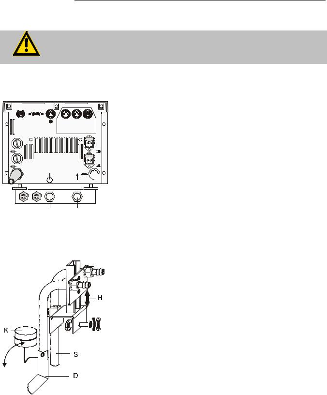
Temperature application to external, open systems
The circulator is equipped with both a pressure and suction pump
for external temperature application in open systems.
Differing flow rates of the pressure and suction pumps should be compensated. To maintain a constant liquid level, the JULABO „D+S“ Level Adapter is recommended for the external bath tank. The flow rate of the pressure pump will be then regulated by a built-in float device. The liquid level may be changed by a height adjustment on the „D+S“ Level Adapter.
Accessory: „D+S“ Level Adapter |
Order No. 8 970 410 |
Important: |
|
|
The liquid level should be equal in the internal and external |
|
baths (absolute height). |
S = Suction pump connection |
If you take out samples (for example Erlenmeyer flasks) from |
D = Pressure pump connection |
the external bath, turn the circulator off with the Start/Stop key. |
K = Float |
|
H = Height adjustment |
|
23
Preparations
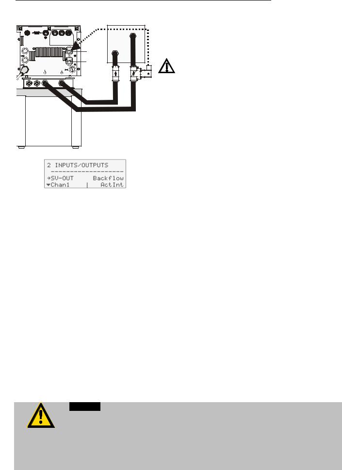
Backflow safety device
ext |
SERIAL |
ALARM STAND-BY |
REG+ |
Pt100 |
|
|
E-PROG |
T16A |
|
|
13 |
|
|
|
|
T16A |
|
|
14 |
|
|
T1.25A |
|
(see page 68
If the liquid levels in the circulator bath and the external system are at different heights, overflowing must be prevented after the power has been turned off.
Flood hazard! |
For this reason, solenoid valves for loop circuit or shut-off valves can be integrated in the loop circuit.
Connect the valve to the connector (13).
If socket (14) is used:
In menu >Inputs/Outputs< set the menu item >SV-Out< to >Backflow<.
Order No. |
Description |
8 980 701 |
Set of solenoid valves |
|
for loop circuit up to +100 °C |
8 970 456 |
Shut-off valve (suitable up to +90 °C) |
8 970 457 |
Shut-off valve (suitable up to +200 °C) |
5.3.1.Tubing
Recommended tubing: |
|
|
|
|
|
Order No. |
Length |
|
|
Temperature range |
|
|
|
||||
8930008 |
1 m |
CR® tubing |
8 mm inner dia. |
-20 °C to 120 °C |
|
8930012 |
1 m |
CR® tubing |
12 mm inner dia. |
-20 °C to 120 °C |
|
8930108 |
1 m |
Viton tubing |
8 mm inner dia. |
-50 °C to 200 °C |
|
8930112 |
1 m |
Viton tubing |
12 mm inner dia. |
-50 |
°C to 200 °C |
8930410 |
1 m |
Insulation for tubing |
8 mm inner dia. |
-50 |
°C to 100 °C |
8930412 |
1 m |
Insulation for tubing |
12 mm inner dia. |
-50 |
°C to 100 °C |
|
|
|
|
||
8 930 209 |
0.5 m |
Metal tubing, triple insulated, M16x1 |
-100 °C to +350 °C |
||
8 930 210 |
1.0 m |
|
|
|
|
8 930 211 |
1.5 m |
|
|
|
|
8 930 214 |
3.0 m |
|
|
|
|
8 930 220 |
0.5 m |
Metal tubing, insulated, M16x1 |
-50 |
°C to +200 °C |
|
8 930 221 |
1.0 m |
|
|
|
|
8 930 222 |
1.5 m |
|
|
|
|
8 930 223 |
3.0 m |
|
|
|
|
Warning: Tubing:
At high working temperatures the tubing used for temperature application and cooling water supply represents a danger source.
A damaged tubing line may cause hot bath fluid to be pumped out within a short time. This may result in:
•Burning of skin
•Difficulties in breathing due to hot atmosphere
24
HL, SL
Safety recommendations
•Employ suitable connecting tubing.
•Make sure that the tubing is securely attached.
•Avoid sharp bends in the tubing, and maintain a sufficient distance from surrounding walls.
•Regularly check the tubing for material defects (e.g. for cracks).
•Preventive maintenance: Replace the tubing from time to time.
5.4.Filling / draining
Notice:
•Pay attention to the thermal expansion of bath oil during heating to avoid overflowing of the liquid.
•Do not drain the bath fluid while it is hot! Recommendation: Temperature range 5 °C to 40 °C
Check the temperature of the bath fluid prior to draining (by switching the unit on for a short moment, for example).
•Store and dispose the used bath fluid according to the laws for environmental protection.
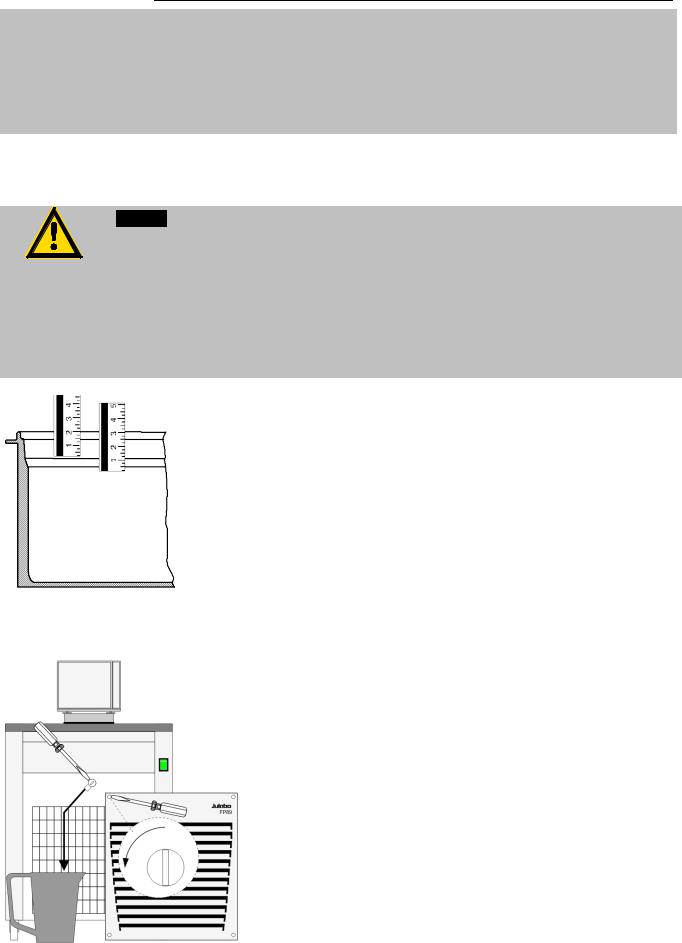
Filling
Take care that no liquid enters the interior of the circulator.
•Recommended maximum filling level with water as bath fluid: 30 mm below the tank rim
•Recommended maximum filling level with bath oils: 40 mm below the tank rim
After filling, immerse the samples in the bath or place the lid on the bath, in case the opening is not to be used.
The circulator provides an early warning system for low level (description – please refer to page 32) that may be triggered when changing samples in the bath.
Draining:
•Turn off the unit and disconnect the mains cable from the power source.
•Hold the venting grid, pull out and remove.
•Slide a short piece of tube onto the drain connection and hold it into a container.
•Loosen the drain screw a few turns and drain the unit completely.
•Tighten the drain tap.
25
Operating procedures
6.Operating procedures
6.1.Power connection
Caution:
•Only connect the unit to a power socket with earthing contact (PE – protective earth)!
•The power supply plug serves as safe disconnecting device from the line and must be always easily accessible.
•Never operate equipment with damaged mains power cables.
•Regularly check the mains power cables for material defects (e.g. for cracks).
•We disclaim all liability for damage caused by incorrect line voltages!
|
Check to make sure that the line voltage matches the supply voltage |
|
specified on the identification plate. |
|
|
Units with |
• Connect the circulator with mains power cable (17a) to the mains |
built-in mains outlet (18) |
outlet (18). |
|
• Connect the refrigerated circulator with mains power cable (17b) to |
|
the mains socket. |
Units without |
• Connect the circulator with mains power cable (17a) to the mains |
built-in mains outlet (18) |
socket. |
•Connect the refrigerating circulator with mains power cable (17b) to the mains socket.
6.2.Switching on / Selecting the language
6.2.1.Switching on the circulator
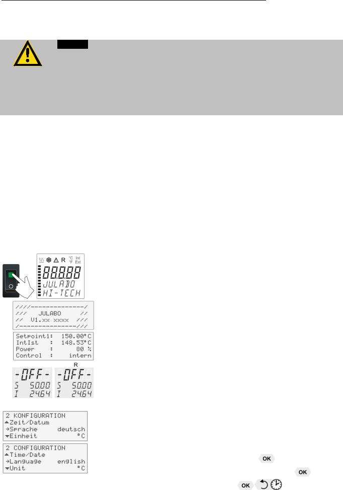
Switching on:
• Turn on the mains power switch (1a).
The unit performs a self-test.
Then the software version (example: V 1.xx-xxxx) appears. The display „OFF“ or „R OFF“ indicates the unit is ready to operate.
The circulator enters the operating mode activated before switching the circulator off:
keypad control mode (manual operation) or
remote control mode (operation via personal computer).
Selecting the language:
There are two options for the language of the LCD DIALOG-DISPLAY: German or English. Select the desired language in the menu >Configuration< under the submenu >Language/Sprache<.
Press the respective keys in the following order:

 3x up to menu Configuration
 6x up to submenu >Language/Sprache<
 deutsch / english
26
HL, SL
6.2.2.Switching on the cooling machine
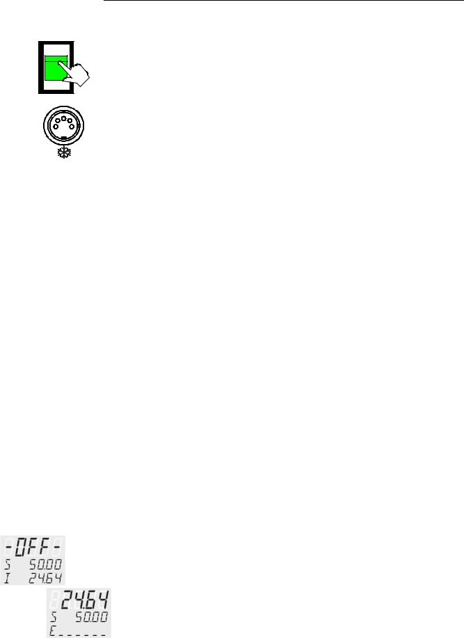
Switching on:
• Switch on the cooling machine using the switch (1b) .
Control of the cooling machine F81, F95, FW95:
With the mains switch (1b) turned on, the circulator automatically switches the cooling machine off and on.
• It is switched off if:
-the current working temperature is increased by > 30 °C (cooling is not required).
-the heater operates at full power (> 800 W) for longer than 5 minutes.
•It is switched on if:
-cooling is necessary to maintain the bath temperature.
After switch-off, the cooling machine automatically switches on only after a delay of 5 minutes to protect the cooling compressor.
To save energy, turn off the cooling machine with the mains switch (1b) whenever cooling is not required.
Control of the FP89 cooling machine:
The mains switch is turned on. After pressing the start/stop button, the cooling machine is automatically switched on or off by the circulator. In the start mode of the circulator, the cooling machine runs continuously. Immediately after starting the cooling machine, the output of the system is reduced to a minimum value for a defined period in order to equilibrate the cooling system. Afterwards the output of the cooling machine is ramped up to the capacity required by the circulator.
A control of the capacity limitation subject to the temperature of the bath is stored in the circulator. This is used to increase the operational reliability and does not affect the maximum capacity of the cooling machine.
6.3.Start - Stop
Start:
•Press  key.
key.
The actual bath temperature is displayed on the VFD COMFORTDISPLAY. The circulating pump starts with a slight delay.
Stop:
•Press  key.
key.
or
Keep  key pressed.
The VFD COMFORT-DISPLAY indicates the message "OFF".
27
Setting of temperatures
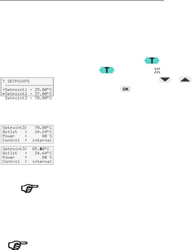
7. Setting of temperatures
Press the  key to call up the menu for temperature selection.
3 different working temperatures can be adjusted. Their values are freely selectable within the operating temperature range.
The temperatures can be set in start or stop mode.
|
Setting of working temperature in the |
menu |
|
||||
Factory settings: |
1. |
Press the key |
. The value flashes |
|
|
||
2. |
Select SETPOINT 1 or 2 or 3 using the key |
or |
. |
||||
|
|||||||
|
3. |
Confirm by pressing the |
key. |
|
|
||
The circulator uses the new working temperature value for temperature control.
Example:
Adjustment/modification of the pre-setting of "SETPOINT 3"
If the active Setpoint is changed, the new value is immediately used for the control of the working temperature.
The heater control indicator flashes.
Setpoint3: |
Change the value from 70.00°C to 80.00°C. |
|
See standard display line 1 |
•Use the numeric keypad to enter  and
and  . Then press enter
  to store the value.
Notice: Refer to SETPOINT MAX / MIN in chapter „LIMITS“
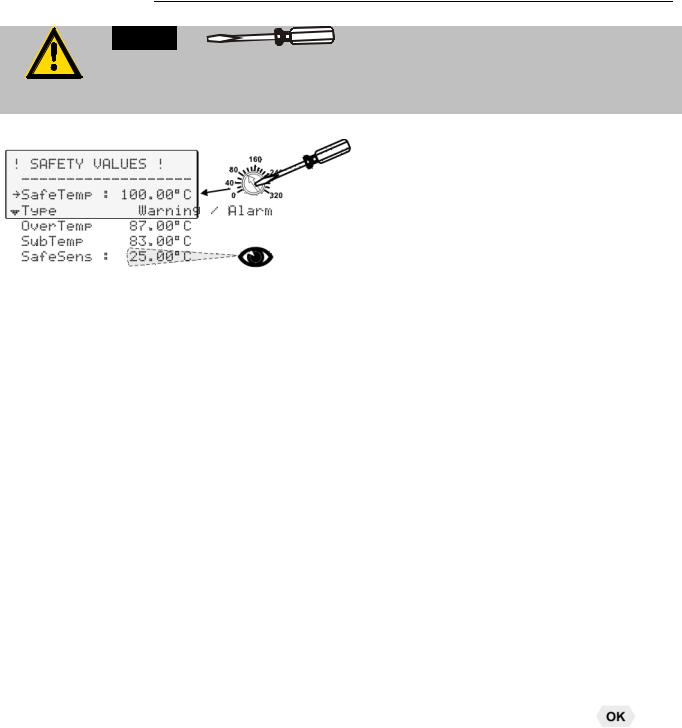
8. Safety installations, warning functions
Check the safety installations at least twice a year! Refer to page 16.
Settings for the excess temperature protection > SafeTemp< and for the warning functions > OverTemp< and > SubTemp< are made in a menu which is called up by pressing the key  .
.
Menu item > Type< allows choosing between a warning and an alarm cut-off for the menu items > OverTemp< and > SubTemp<.
28
HL, SL
Warning:
Adjust excess-temperature safety device below the flash point of the bath fluid. In case of wrong setting there is a fire hazard!
We disclaim all liability for damage caused by wrong settings!
SafeTemp:
Type:
OverTemp :
SubTemp:
 SafeSens:
SafeTemp:
Setting range: 20 °C ... 320 °C
Rough setting can be effected by using the temperature scale.
Settings:
•Press the key  and by pressing the key
  or
or  select the menu item
  and confirm the by pressing the key
  .
.
For setting proceed as follows.
•Set the new cut-out value within 30 seconds with a screw driver. Exact display and setting on LCD display
Recommendation:
Set over temperature-protective setting >SafeTemp< 5 °C to 10 °C above the set point of the working temperature.
•
Switch-over from warning to shutdown function
•Change the parameter by pressing the key  and confirm by
pressing the key  . or
. or
pressing the key  if the parameter is to be retained. Possible parameters: warning or alarm
•Set value on numeric keypad and confirm by pressing  Example: 83.00 °C
Press the keys and
and  and confirm by pressing
•
Indicated is the temperature value of the safety sensor.
SafeTemperature:
Setting range: 20 °C ... 320 °C
Indicated is the cut-out value set with a screwdriver on the excess temperature protection device.
This safety installation is independent of the control circuit. When the temperature of the bath fluid has reached the safety temperature, a complete shutdown of the heater and pump is effected.
The alarm is indicated by optical and audible signals (continuous tone). The following error message appears on the VFD COMFORT-DISPLAY:
29
Loading...