


 Loading...
Julabo F12-MA, FP35-MA, F25-MA, FP40-MA, F33-MA Operating Manual
...English
OPERATING MANUAL
Refrigerated and Heating
Circulators
F12-MA FP35-MA
F25-MA FP40-MA
F33-MA FP50-MA
F32-MA
F34-MA FPW50-MA
JULABO USA, Inc.
884 Marcon Boulevard
Allentown, PA 18109
Phone: +1(610) 231-0250
Fax: |
+1(610) 231-0260 |
Original Operating Manual |
info.us@ julabo.com |
www.julabo.com |
|
19530366-V3.doc |
16.02.16 |

Operating manual
Congratulations!
You have made an excellent choice.
JULABO thanks you for the trust you have placed in us.
This operating manual has been designed to help you gain an understanding of the operation and possible applications of our circulators. For optimal utilization of all functions, we recommend that you thoroughly study this manual prior to beginning operation.
The JULABO Quality Management System
Temperature control devices for research and industry are developed, produced, and distributed according to the requirements of ISO 9001 and ISO 14001. Certificate Registration No. 01 100044846
Unpacking and inspecting
Unpack the circulator and accessories and inspect them for possible transport damage. Damage should be reported to the responsible carrier, railway, or postal authority, and a damage report should be requested. These instructions must be followed fully for us to guarantee our full support of your claim for protecting against loss from concealed damage. The form required for filing such a claim will be provided by the carrier.
1.953.0366-V1 02/16 Printed in Germany |
Changes without prior notification reserved |
Important: keep operating manual for future use
2

MA
TABLE OF CONTENTS
Operating manual .......................................................................................................... |
|
5 |
|
1. |
Intended use .......................................................................................................... |
|
5 |
|
1.1. Description ......................................................................................................... |
|
5 |
2. |
Operator responsibility – Safety recommendations |
...............................................6 |
|
|
2.1. Disposal.............................................................................................................. |
|
8 |
|
2.2. Technical specifications ..................................................................................... |
|
9 |
|
2.3. Cooling water connection................................................................................. |
|
14 |
Operating instructions .................................................................................................. |
|
15 |
|
3. |
Safety notes for the user ...................................................................................... |
|
15 |
|
3.1. Explanation of safety notes .............................................................................. |
|
15 |
|
3.2. Explanation of other notes ............................................................................... |
|
15 |
|
3.3. Safety recommendations ................................................................................. |
|
15 |
4. |
Operating controls and functional elements......................................................... |
18 |
|
|
4.1. Circulator .......................................................................................................... |
|
18 |
|
4.2. Cooling Machine............................................................................................... |
|
20 |
5. |
Preparations......................................................................................................... |
|
21 |
|
5.1. Installation ........................................................................................................ |
|
21 |
|
5.2. Bath fluids......................................................................................................... |
|
22 |
|
5.3. Temperature application to external systems .................................................. |
23 |
|
|
5.3.1. Tubing ...................................................................................................... |
|
23 |
|
5.4. Filling / draining ................................................................................................ |
|
25 |
6. |
Operating procedures .......................................................................................... |
|
26 |
|
6.1. Power connection............................................................................................. |
|
26 |
|
6.2. Switching on / Start – Stop............................................................................... |
|
26 |
|
6.2.1. Switching on the circulator ....................................................................... |
|
26 |
|
6.2.2. Switching on the cooling machine............................................................ |
27 |
|
7. |
Setting of temperatures ............................................................................ |
|
28 |
|
7.1. 1-setpoint mode / Direct setting of temperatures ............................................. |
28 |
|
|
7.2. Using the pre-setting in the |
menu ........................................................ |
28 |
8. |
Safety installations, warning functions ..................................................... |
30 |
|
|
8.1. Excess temperature protection ........................................................................ |
|
30 |
3

Operating manual |
|
|
|
||
|
8.1.1. Early warning system, low level protection .............................................. |
31 |
|||
8.2. Switch-over from warning to shutdown function .............................................. |
32 |
||||
8.3. Over and Sub temperature warning function |
................................................... |
|
33 |
||
9. |
|
Menu functions......................................................................................... |
|
|
34 |
9.1. MENU PUMP – Setting of pump pressure....................................................... |
|
|
35 |
||
9.2. MENU Configuration ........................................................................................ |
|
|
36 |
||
|
9.2.1. Configuration of the mode of the ........................................... |
key |
37 |
||
|
9.2.2. Remote control: activate – deactivate...................................................... |
|
|
37 |
|
|
9.2.3. Automatic / non-automatic start mode ..................................................... |
|
|
37 |
|
|
9.2.4. Reset - Factory setting............................................................................. |
|
|
38 |
|
9.3. MENU Control parameters – Xp, Tv, Tn .......................................................... |
|
|
38 |
||
9.4. MENU SERIAL - BAUDRATE, PARITY, HANDSHAKE .................................. |
40 |
||||
9.5. MENU ATC - Absolut Temperature Calibration ............................................... |
41 |
||||
|
9.5.1. ATC STATUS - YES / NO........................................................................ |
|
|
43 |
|
|
9.5.2. ATC - TYPE: 1 -/ 2 -/ 3 POINT................................................................. |
|
|
43 |
|
|
9.5.3. Example: 3-point calibration for internal ......................................control |
44 |
|||
9.6. MENU LIMITS .................................................................................................. |
|
|
46 |
||
10. |
Troubleshooting guide / error messages ............................................................. |
|
|
47 |
|
11. |
Electrical connections .......................................................................................... |
|
|
50 |
|
12. |
Remote control..................................................................................................... |
|
|
51 |
|
12.1. Setup for remote control .............................................................................. |
|
|
51 |
||
12.2. Communication with a PC or a superordinated .......................data system |
51 |
||||
12.3. |
List of commands......................................................................................... |
|
|
52 |
|
12.4. |
Status messages ......................................................................................... |
|
|
53 |
|
12.5. |
Error messages............................................................................................ |
|
|
53 |
|
13. |
JULABO Service – Online remote diagnosis ....................................................... |
|
|
55 |
|
14. |
Cleaning / repairing the unit ................................................................................. |
|
|
56 |
|
15. |
WARRANTY PROVISIONS ................................................................................. |
|
|
57 |
|
4

MA
Operating manual
1.Intended use
JULABO circulators have been designed to control the temperature of specific fluids in a bath tank.
The units feature pump connections for temperature control of external systems (loop circuit).
JULABO circulators are not suitable for direct temperature control of foods, semi-luxury foods and tobacco, or pharmaceutical and medical products.
Direct temperature control means unprotected contact of the object with the bath medium (bath fluid).
1.1.Description
The circulators are operated via the splash-proof keypad. The implemented microprocessor technology allows to set and to store different values that can be indicated on the MULTI-DISPLAY (LED). Three menu keys facilitate adjusting setpoints, warning and safety functions and menu functions.
The PID temperature control adapts the heat supplied to the thermal requirements of the bath.
PID2 |
Absolute Temperature Calibration (ATC3) provides a high temperature |
stability in the bath. With the 3-point calibration an offset is adjusted at three |
|
|
temperatures to ensure an accurate temperature pattern at the selected spot |
ATC3 |
in the bath over the full temperature range. |
Electrical connections: |
|
|
The serial interface RS232 allows modern process technology without |
RS232 |
additional interface. |
Alarm output for external alarm message or control of JULABO refrigerating |
|
|
baths or solenoid valve (cooling water). |
|
The excess temperature protection conforming to IEC 61010-2-010 is a |
|
safety installation independent from the control circuit. This protection can be |
|
indicated and set on the MULTI-DISPLAY (LED). |
|
The early warning system for low level signals that bath fluid needs to be |
|
refilled before the low level protection conforming to IEC 61010-2-010 |
|
causes a complete shut-down of the main functional elements. |
|
The pump capacity (electronically adjustable via the motor speed) enables to |
|
adapt to varying conditions for internal and external temperature |
SMART |
applications. |
PUMP |
The circulator conforms to the relevant requirements specified by European |
|
guidelines. |
5

Operator responsibility – Safety recommendations
2.Operator responsibility – Safety recommendations
The products of JULABO ensure safe operation when installed, operated, and maintained according to common safety regulations. This section explains the potential dangers that may arise when operating the circulator and also specifies the most important safety precautions to preclude these dangers as far as possible.
The operator is responsible for the qualification of the personnel operating the units.
The personnel operating the units should be regularly instructed about the dangers involved with their job activities as well as measures to avert these dangers.
Make sure all persons tasked with operating, installing, and maintaining the unit have read and understand the safety information and operating instructions.
When using hazardous materials or materials that could become hazardous, the circulator may be operated only by persons who are absolutely familiar with these materials and the circulator. These persons must be fully aware of possible risks.
If you have any questions concerning the operation of your unit or the information in this manual, please contact us!
Contact |
JULABO USA, Inc. |
Phone:+1(610) 231-0250 |
|
884 Marcon Boulevard |
Fax: +1(610) 231-0260 |
|
Allentown, PA 18109 |
info.us@ julabo.com |
|
|
www.julabo.com |
Safety instructions for the operator:
You have received a product designed for industrial use. Nevertheless, avoid strikes to the housing, vibrations, damage to the operating-element panel (keypad, display), and contamination.
Make sure the product is checked for proper condition regularly (depending on the conditions of use). Regularly check (at least every 2 years) the proper condition of the mandatory, warning, prohibition and safety labels.
Make sure that the mains power supply has low impedance to avoid any negative effects on instruments being operated on the same mains.
This unit is designed for operation in a controlled electromagnetic environment. This means that transmitting devices (e.g., cellular phones) should not be used in the immediate vicinity.
Magnetic radiation may affect other devices with components sensitive to magnetic fields (e.g., monitors). We recommend maintaining a minimum distance of 1 m.
Permissible ambient temperature: max. 40 °C, min. 5 °C.
Permissible relative humidity: 50% (40 °C).
Do not store the unit in an aggressive atmosphere.
Protect the unit from contamination.
Do not expose the unit to sunlight.
6

MA
Appropriate operation
Only qualified personnel is authorized to perform configuration, installation, maintenance and repairs of the circulator.
Routine operation can also be carried out by untrained personnel who should however be instructed by trained personnel.
Use:
The bath can be filled with flammable materials. Fire hazard!
There might be chemical dangers depending on the bath medium used.
Observe all warnings for the used materials (bath fluids) and the respective instructions
(safety data sheets).
Insufficient ventilation may result in the formation of explosive mixtures. Only use the unit in well ventilated areas.
Only use recommended materials (bath fluids). Only use non-acid and non corroding materials.
When using hazardous materials or materials that could become hazardous, the operator must affix the enclosed safety labels to the front of the unit so they are highly visible:
If this unit is intended for use within the United States of America, all 3 warning labels must be affixed to the housing of the unit prior to use.
Directions for the positioning of the individual warning labels are enclosed with the warning labels included in the delivery. Warning labels must be easily visible to users.
1 |
Warning label W00: |
Colors: yellow, black |
|
Danger area. Attention! Observe instructions. |
|
|
(operating manual, safety data sheet) |
|
|
|
|
2 |
Mandatory label M018: |
Colors: blue, white |
|
Carefully read the user information prior to beginning operation. |
|
or |
Scope: EU |
|
|
|
|
2 |
Semi S1-0701 Table A1-2 #9 |
|
|
Carefully read the user information prior to beginning operation. |
|
|
Scope: USA, NAFTA |
|
|
|
|
3 |
Warning label Proposition 65 |
|
|
|
|
Particular care and attention is necessary because of the wide operating range. There are thermal dangers: Burn, scald, hot steam, hot parts and surfaces that can be touched.
Warning label W26: |
Colors: yellow, black |
Hot surface warning.
(The label is put on by JULABO)
Observe the instructions in the manuals for instruments of a different make that you connect to the circulator, particularly the respective safety recommendations. Also observe the pin assignment of plugs and technical specifications of the products.
7

Operator responsibility – Safety recommendations
2.1.Disposal
The circulator contains a back-up battery that supplies voltage to memory chips when the unit is switched off. Do not dispose of the battery with household waste!
Depending on battery regulations in your country, you might be obliged to give back used or defect batteries to gathering places.
The product may be used with oil as bath fluid. These oils fully or partially consist of mineral oil or synthetic oil. For disposal, observe the instructions in the safety data sheets.
These units contains refrigerants– at this time considered not to have any negative effects on the ozone layer. However, during the long operating period of the unit, disposal prescriptions may change. So only qualified personnel should take care of disposal.
Contact an authorized waste management company in your country.
Disposal with household waste (unsorted waste) or similar collections of municipal waste is not permitted!
8

MA
2.2.Technical specifications
|
|
|
|
F12-MA |
|
|
F25-MA |
|
|
|
|
|
|
||
Working temperature range |
°C |
-20 ... 200 |
|
-28 ... 200 |
|||
Temperature stability |
|
°C |
±0,02 |
|
±0,02 |
||
Cooling capacity |
|
°C |
+20 0 |
-20 |
+20 0 -20 |
||
Medium ethanol |
|
kW |
0.16 0.1 |
0.02 |
0.26 0.2 0.06 |
||
Refrigerant |
|
|
|
R134a |
|
|
R134a |
Overall dimensions |
(WxDxH) |
cm |
|
20x36x56 |
|
|
23x42x61 |
Bath opening |
(WxL) |
cm |
|
13x15 |
|
|
12x14 |
Bath depth |
|
cm |
13 |
|
14 |
||
Filling volume |
from ... to |
liters |
|
3 ... 4,5 |
|
|
3 ... 4,5 |
Weight |
|
kg |
23 |
|
31 |
||
Mains power connection |
|
V/ Hz |
230 / 50 |
|
230 / 50 |
||
Current draw |
(at 230 V) |
A |
11 |
|
12 |
||
Current draw |
CH (at 230 V) |
A |
<9 / 1> |
|
<9 / 2> |
||
Mains power connection |
|
V/ Hz |
208-230 / 50/60 |
208-230 / 50/60 |
|||
Current draw |
(at 208 V / 230 V) |
A |
11 |
|
12 |
||
|
|
|
|
|
|
||
Mains power connection |
|
V/ Hz |
115 / 60 |
|
115 / 60 |
||
Current draw |
(at 115 V) |
A |
12 |
|
13 |
||
Mains power connection |
|
V/ Hz |
100 / 50/60 |
100 / 50/60 |
|||
Current draw |
(at 100 V) |
A |
15 |
|
13 |
||
|
|
|
|
|
|
|
|
F32-MA |
|
|
Working temperature range |
|
|
°C |
-35 ... 200 |
|
|||
|
Temperature stability |
|
|
°C |
|
|
|
±0,02 |
|
|
Cooling capacity |
|
|
°C |
+20 0 -20 |
|
|||
|
Medium ethanol |
|
|
kW |
0.45 0.39 0.15 |
|
|||
|
Refrigerant |
|
|
|
|
|
|
R134a |
|
|
Overall dimensions |
(WxDxH) |
|
cm |
|
31x42x64 |
|
||
|
Bath opening |
(WxL) |
|
cm |
|
18x12 |
|
||
|
Bath depth |
|
|
cm |
15 |
|
|||
|
Filling volume |
from ... to |
|
liters |
5,5 ... 8 |
|
|||
|
Weight |
|
|
kg |
37 |
|
|||
|
|
|
|
|
|
|
|
|
|
|
Mains power connection |
230 V/50 Hz |
|
V/ Hz |
|
230 / 50 |
|
||
|
|
|
|
|
|||||
|
Current draw |
(at 230 V) |
|
A |
12 |
|
|||
|
Current draw |
CH (at 230 V) |
|
A |
|
|
|
<9 / 2> |
|
|
Mains power connection |
230 V/60 Hz |
|
V/ Hz |
208-230 / 60 |
|
|||
|
Current draw |
(at 230V) |
|
A |
12 |
|
|||
|
Current draw |
(at 208V) |
|
A |
10 |
|
|||
|
Mains power connection |
115 V/60 Hz |
|
V/ Hz |
115 / 60 |
|
|||
|
Current draw |
(at 115 V) |
|
A |
14 |
|
|||
|
Mains power connection 100 V/50-60 Hz |
|
V/ Hz |
100 / 50-60 |
|
||||
|
Current draw |
(at 100 V) |
|
A |
14 |
|
|||
|
All measurements have been carried out at: rated voltage and frequency |
|
|
|
|||||
|
ambient temperature: 20 °C |
Technical changes without prior notification reserved. |
|
||||||
9

Operator responsibility – Safety recommendations
|
|
|
|
|
|
|
F33-MA |
|
|
|
F34-MA |
|
|
|
|
|
Working temperature range |
|
|
°C |
-30 ... 200 |
-30 ... 150 |
|
|
|||||||
|
Temperature stability |
|
|
|
°C |
|
±0,02 |
|
|
|
±0,02 |
|
|
|
|
|
Cooling capacity |
|
|
|
°C |
+20 0 -20 -30 |
+20 |
0 |
-20 |
-30 |
|
||||
|
Medium ethanol |
|
|
|
kW |
0.5 0.32 0.12 0.03 |
0.45 |
0.32 |
0.14 |
0.03 |
|
||||
|
Refrigerant |
|
|
|
|
|
R134a |
|
|
|
R134a |
|
|
|
|
|
Overall dimensions |
|
(WxDxH) |
|
cm |
|
36x46x69 |
|
|
|
38x58x62 |
|
|
||
|
Bath opening |
|
(WxL) |
|
cm |
|
23x14 |
|
|
|
24x30 |
|
|
|
|
|
Bath depth |
|
|
|
cm |
20 |
|
|
|
15 |
|
|
|
|
|
|
Filling volume |
|
from ... to |
|
liters |
|
12 ... 16 |
|
14 ... 20 |
|
|
|
|||
|
Weight |
|
|
|
kg |
44 |
42 |
|
|
|
|
||||
|
|
|
|
|
|
|
|
|
|
|
|||||
|
Mains power connection |
|
|
V/ Hz |
230 / 50 |
|
|
230 / 50 |
|
|
|
||||
|
Current draw |
|
(at 230 V) |
|
A |
12 |
|
|
|
12 |
|
|
|
|
|
|
Current draw |
|
CH (at 230 V) |
|
A |
<9 / 2> |
|
|
<9 / 2> |
|
|
|
|||
|
Mains power connection |
230 V/60 Hz |
|
V/ Hz |
230 / 60 |
|
|
|
230 / 60 |
|
|
|
|||
|
Current draw |
(at 208 V / 230 V) |
|
A |
12 |
|
|
13 |
|
|
|
|
|||
|
|
|
|
|
|
|
|
|
|
|
|
||||
|
Mains power connection |
|
|
V/ Hz |
|
115 / 60 |
|
115 / 60 |
|
|
|
||||
|
Current draw |
|
(at 115 V) |
|
A |
15 |
14 |
|
|
|
|
||||
|
Mains power connection |
|
|
V/ Hz |
|
100 / 50/60 |
|
----- |
|
|
|
|
|||
|
Current draw |
|
(at 100 V) |
|
A |
15 |
----- |
|
|
|
|
||||
|
|
|
|
|
|
|
|
FP35-MA |
|||
|
Working temperature range |
|
|
|
|
°C |
-35 ... 150 |
|
|
|
|
|
Temperature stability |
|
|
|
|
°C |
±0,02 |
|
|
|
|
|
Cooling capacity |
|
|
|
|
°C |
+20 0 -20 -30 |
|
|
|
|
|
Medium ethanol |
|
|
|
|
kW |
0.45 0.39 0.15 0.05 |
|
|
|
|
|
Refrigerant |
|
|
|
|
|
|
R134a |
|
|
|
|
Overall dimensions |
|
(WxDxH) |
|
cm |
|
31x42x64 |
||||
|
|
|
|
|
|
|
|
|
|
||
|
Bath opening |
|
(WxL) |
|
cm |
|
18x12 |
||||
|
Bath depth |
|
|
|
|
cm |
5 |
|
|
|
|
|
Filling volume |
|
from ... to |
|
liters |
1,7 ... 2.5 |
|
|
|
||
|
Weight |
|
|
|
|
kg |
37 |
|
|
|
|
|
|
|
|
|
|
|
|
|
|
|
|
|
Mains power connection |
|
|
|
|
V/ Hz |
|
230 / 50 |
|
|
|
|
Current draw |
|
(at 230 V) |
|
|
A |
12 |
|
|
|
|
|
Current draw |
CH (at 230 V) |
|
|
|
|
<9 / 2> |
|
|
|
|
|
|
|
|
|
|
|
|
|
|
|
|
|
|
|
|
|
|
|
|
|
|
|
|
|
Mains power connection |
|
|
|
|
V/ Hz |
115 / 60 |
|
|
|
|
|
Current draw |
|
(at 115 V) |
|
A |
14 |
|
|
|
||
|
Mains power connection |
|
|
|
|
V/ Hz |
100 / 50/60 |
|
|
|
|
|
Current draw |
|
(at 100 V) |
|
A |
14 |
|
|
|
||
|
All measurements have been carried out at: rated voltage and frequency |
||||||||||
|
ambient temperature: 20 °C |
Technical changes without prior notification reserved. |
|||||||||
10
MA
FP40-MA
|
|
Working temperature range |
|
|
°C |
-40 ... 200 |
|
|
|
||||
|
|
Temperature stability |
|
|
|
°C |
±0,02 |
|
|
|
|
||
|
|
Cooling capacity |
|
|
|
°C |
+20 |
0 |
-20 |
-30 -40 |
|
|
|
|
|
Medium ethanol |
|
|
|
kW |
0.68 0.5 0.32 0.17 0.04 |
|
|
||||
|
|
Refrigerant |
|
|
|
|
|
R404A |
|
|
|
|
|
|
|
Overall dimensions |
|
(WxDxH) |
|
cm |
|
37x46x69 |
|
|
|
||
|
|
Bath opening |
|
(WxL) |
|
cm |
|
23x14 |
|
|
|
|
|
|
|
Bath depth |
|
|
|
cm |
20 |
|
|
|
|
|
|
|
|
Filling volume |
|
from ... to |
|
liters |
|
9 ... 16 |
|
|
|
|
|
|
|
Weight |
|
|
|
kg |
48 |
|
|
|
|
|
|
|
|
|
|
|
|
|
|
|
|
|
|
||
|
|
Mains power connection |
|
|
|
V/ Hz |
230 / 50 |
|
|
|
|
||
|
|
Current draw |
|
(at 230 V) |
|
A |
13 |
|
|
|
|
|
|
|
|
Current draw |
GB, CH (at 230 V) |
|
A |
<9 / 3> |
|
|
|
|
|||
|
|
Mains power connection |
|
|
|
V/ Hz |
|
230 / 60 |
|
|
|
|
|
|
|
Current draw |
|
(at 230 V) |
|
A |
13 |
|
|
|
|
|
|
|
|
|
|
|
|
|
|
|
|
||||
|
|
|
|
|
|
|
|
FP50-MA / FPW50-MA |
|
||||
|
|
Working temperature range |
|
|
°C |
-50 ... 200 |
|
|
|
||||
|
|
Temperature stability |
|
|
|
°C |
|
±0,02 |
|
|
|
|
|
|
|
Cooling capacity |
|
|
|
°C |
+20 |
0 |
-20 |
-30 -40 |
|
|
|
|
|
Medium ethanol |
|
|
|
kW |
0.9 |
0.8 |
0.5 |
0.32 0.16 |
|
|
|
|
|
Refrigerant |
|
|
|
|
|
R404A / R507 |
|
|
|||
|
|
Overall dimensions |
|
(WxDxH) |
|
cm |
|
42x49x70 |
|
|
|
||
|
|
Bath opening |
|
(WxL) |
|
cm |
|
18x12 |
|
|
|
|
|
|
|
Bath depth |
|
|
|
cm |
15 |
|
|
|
|
|
|
|
|
Filling volume |
|
from ... to |
|
liters |
5,5 ... 8 |
|
|
|
|
||
|
|
Weight |
|
|
|
kg |
55 |
|
|
|
|
|
|
|
|
|
|
|
|
|
|
|
|
|
|
||
|
|
Mains power connection |
|
|
|
V/ Hz |
230 / 50 |
|
|
|
|
||
|
|
Current draw |
|
(at 230 V) |
|
A |
|
14 |
|
|
|
|
|
|
|
Current draw |
|
CH (at 230 V) |
|
A |
<9 / 4> |
|
|
|
|
||
|
|
|
|
|
|
|
|
|
|
|
|
|
|
|
|
Mains power connection |
|
|
|
V/ Hz |
|
230 / 60 |
|
|
|
|
|
|
|
Current draw |
|
(at 230 V) |
|
A |
14 |
|
|
|
|
|
|
|
|
All measurements have been carried out at: rated voltage and frequency |
|
||||||||||
|
|
ambient temperature: 20 °C |
Technical changes without prior notification reserved. |
|
|||||||||
11

Operator responsibility – Safety recommendations
|
|
|
|
MA |
Temperature selection |
|
|
digital |
|
via keypad |
|
indication on |
|
MULTI-DISPLAY(LED) |
remote control via personal computer |
|
indication on monitor |
||
Temperature indication |
|
|
MULTI-DISPLAY (LED) |
|
Resolution |
(-9.99 …. +99.99 = 0.01) |
°C |
0.01 / 0.1 |
|
Absolute Temperature Calibration |
°C |
±3 |
||
Temperature control |
|
|
PID |
|
Heater wattage |
|
(at 230 V) |
kW |
2,0 |
Heater wattage |
|
(at 115V) |
kW |
1,0 |
Electronically adj. pump capacity |
stages |
1 ... 4 |
||
Flow rate |
|
max.at 0 bar |
l/min |
11 ... 16 |
Pressure max. |
max. at 0 l |
bar |
0.23 ... 0.45 |
|
Electrical connections: |
|
|
|
|
External alarm device |
|
Vdc/mA |
24-0 / max. 25 |
|
Computer interface |
|
|
RS232 |
|
Ambient temperature |
|
°C |
5 ... 40 |
|
Safety installations according to IEC 61010-2-010: |
|
|||
Excess temperature protection |
adjustable from 0 °C ... 230 °C |
|||
Low liquid level protection |
|
float switch |
|
|
Classification according to DIN 12876-1 |
class III |
|
||
Supplementary safety installations |
|
|
||
Early warning system for low level |
float switch |
|
||
High temperature warning function |
optical + audible (in intervals) |
|||
Low temperature warning function |
optical + audible (in intervals) |
|||
Supervision of working sensor |
plausibility control |
|||
Reciprocal sensor monitoring between |
|
|
||
working and safety sensors |
|
difference >35 K |
||
Alarm message |
|
|
optical + audible (permanent) |
|
Warning message |
|
optical + audible (in intervals) |
||
Environmental conditions according to IEC 61 010-1: Use only indoor.
Altitude up to 2000 m - normal zero. Ambient temperature: +5 ... +40 °C
Air humidity:
Max. rel. humidity 80 % for temperatures up to +31 °C,
linear decrease down to 50 % relative humidity at a temperature of +40 °C
Max. mains fluctuations of ±10 % are permissible.
12

MA
Protection class according to IEC 60 529 |
IP21 |
The unit corresponds to Class |
I |
Overvoltage category |
II |
Pollution degree |
2 |
Caution:
The unit is not for use in explosive environment
Standards for interference resistance according to EN 61326-1
This unit is an ISM device classified in Group 1 (using high frequency for internal purposes) Class A (industrial and commercial range).
Information about the used refrigerants
The Regulation (EU) No. 517/2014 on fluorinated greenhouse gases applies to all systems which contain fluorinated refrigerants and replaces (EC) 842/2006.
The aim of the Regulation is to protect the environment by reducing emissions of fluorinated greenhouse gases.
Among other things it regulates the emission limits, use and recovery of these substances. It also contains requirements for operators of systems which require / contain these substances to function.
Under Regulation 517/2014, the operator of a system of this nature has the following duties:
•The operator must ensure that the equipment is checked at regular intervals for leaks.
•These intervals depend on the CO2 equivalent of the system. This is calculated from the refrigerant fill volume and type of refrigerant. The CO2 equivalent of your system is shown on the model plate.
•The operator undertakes to have maintenance, repair, service, recovery and recycling work carried out by certified personnel who have been authorized by JULABO.
•All such work must be documented. The operator must keep records and archive them for at least five years. The records must be submitted to the relevant authority on request.
Refer to the text of the Regulation for further information.
13

Operator responsibility – Safety recommendations
2.3.Cooling water connection
Cooling water pressure (IN/OUT) |
max. |
6 bar |
|
Pressure difference (IN - OUT) |
|
3.5 to 6 bar |
|
Cooling water temperature |
|
|
< 20 °C |
Notice: |
Cooling water circuit |
|
|
Risk of oil leaking from the refrigeration system (compressor) of the recirculating cooler into the cooling water in case of a fault in the cooling water circuit!
Observe the laws and regulations of the water distribution company valid in the location where the unit is operated.
Notice:
Danger of corrosion of heat exchanger due to unsuitable quality of cooling water.
•Due to its high content of lime, hard water is not suitable for cooling and causes scale in the heat exchanger.
•Ferrous water or water containing ferrous particles will cause formation of rust even in heat exchangers made of stainless steel.
•Chlorinated water will cause pitting corrosion in heat exchangers made of stainless steel.
•Due to their corrosive characteristics, distilled water and deionized water are unsuitable and will cause corrosion of the bath.
•Due to its corrosive characteristics, sea water is not suitable.
•Due to its microbiological (bacterial) components, which settle in the heat exchanger, untreated and unpurified river water and water from cooling towers is unsuitable.
•Avoid particulate matter in cooling water.
•Avoid putrid water.
Recommended quality of cooling water:
pH |
7.5 to 9.0 |
Sulfate [SO4 2- ] |
< 100 ppm |
Hydrocarbonate [HCO 3-]/sulfate [SO4 2-] |
> 1 ppm |
Hardness [Ca 2+, Mg 2+]/[HCO 3-] |
> 0.5 °dH |
Alkalinity |
60 ppm < [HCO 3-] < 300 ppm |
Conductivity |
< 500 μS/cm |
Chloride (Cl -) |
< 50 ppm |
Phosphate (PO4 3-) |
< 2 ppm |
Ammonia (NH3) |
< 0.5 ppm |
Free chlorine |
< 0.5 ppm |
Trivalent iron ions (Fe 3+) |
< 0.5 ppm |
Manganese ions (Mn 2+) |
< 0.05 ppm |
Carbon dioxide (CO2) |
< 10 ppm |
Hydrogen sulfide (H2S) |
< 50 ppm |
Content of oxygen |
< 0.1 ppm |
Algae growth |
impermissible |
Suspended solids |
impermissible |
14
MA
Operating instructions
3.Safety notes for the user
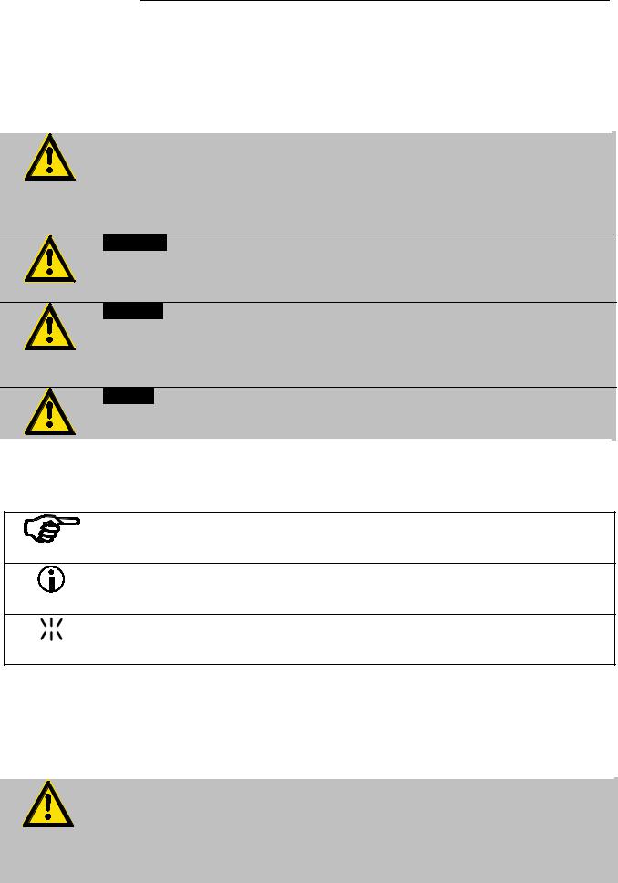
3.1.Explanation of safety notes
In addition to the safety warnings listed, warnings are posted throughout the operating manual. These warnings are designated by an exclamation mark inside an equilateral triangle. “Warning of a dangerous situation (Attention!
Please follow the documentation).”
The danger is classified using a signal word.
Read and follow these important instructions for averting dangers.
Warning:
Describes a possibly highly dangerous situation. If these instructions are not followed, serious injury and danger to life could result.
Caution:
Describes a possibly dangerous situation. If this is not avoided, slight or minor injuries could result. A warning of possible property damage may also be contained in the text.
Notice:
Describes a possibly harmful situation. If this is not avoided, the product or anything in its surroundings can be damaged.
3.2.Explanation of other notes
Note!
Draws attention to something special.
Important!
Indicates usage tips and other useful information.
This icon is used in the operating instructions to indicate flashing values or parameters which have to be set or confirmed.
3.3.Safety recommendations
Follow the safety instructions to avoid personal injury and property damage. Also, the valid safety instructions for workplaces must be followed.
•Only connect the unit to a power socket with an earthing contact (PE – protective earth)!
•The power supply plug serves as a safe disconnecting device from the line and must always be easily accessible.
•Place the unit on an even surface on a base made of nonflammable material.
15

Safety notes for the user
•Do not stay in the area below the unit.
•Make sure you read and understand all instructions and safety precautions listed in this manual before installing or operating your unit.
•Set the excess temperature safety installation at least 25 °C below the fire point of the bath fluid.
•Observe the limited working temperature range when using plastic bath tanks.
•Never operate the unit without bath fluid in the bath.
•Pay attention to the thermal expansion of bath oil during heating to avoid overflowing of the fluid.
•Prevent water from entering the hot bath oil.
•Do not drain the bath fluid while it is hot!
Check the temperature of the bath fluid prior to draining (e.g., by switching the unit on for a short moment).
•Use suitable connecting tubing.
•Avoid sharp bends in the tubing, and maintain a sufficient distance from surrounding walls.
•Make sure that the tubing is securely attached.
•Regularly check the tubing for material defects (e.g., for cracks).
•Never operate damaged or leaking units.
•Always turn off the unit and disconnect the mains cable from the power source before performing any service or maintenance procedures, or before moving the unit.
•Always turn off the unit and disconnect the mains cable from the power source before cleaning the unit.
•Always empty the bath before moving the unit.
•Transport the unit with care.
•Sudden jolts or drops may cause damage in the interior of the unit.
•Observe all warning labels.
•Never remove warning labels.
•Never operate units with damaged mains power cables.
•Repairs are to be carried out only by qualified service personnel.
Some parts of the bath tank and the pump connections may become extremely hot during continuous operation. Therefore, exercise particular caution when touching these parts.
Caution:
The temperature controlling i.e. of fluids in a reactor constitutes normal circulator practice.
We do not know which substances are contained within these vessels.
Many substances are:
•inflammable, easily ignited or explosive
•hazardous to health
•environmentally unsafe
i.e.: dangerous
16

MA
The user alone is responsible for the handling of these substances!
The following questions shall help to recognize possible dangers and to reduce the risks to a minimum.
•Are all tubes and electrical cables connected and installed?
Note:
sharp edges, hot surfaces in operation, moving machine parts, etc.
•Do dangerous steams or gases arise when heating? Is an exhaust needed when working?
•What to do when a dangerous substance was spilled on or in the unit? Before starting to work, obtain information concerning the substance and determine the method of decontamination.
Notice: Check the safety installations at least twice a year!
•Excess temperature protection according to IEC 61010-2-010.
With a screwdriver turn back the adjustable excess temperature protection until the shut-down point (actual temperature).
•Low level protection according to IEC 61010-2-010.
To check the function of the float, it can be manually lowered with a screwdriver for example.
WARNING
This product contains chemicals known to the state of California to cause cancer, birth defects or other reproductive harm.
17

Operating controls and functional elements
4.Operating controls and functional elements
4.1.Circulator
Front view |
Rear view |
1 |
Mains power switch, illuminated |
|||
|
Navigation keys |
|
|
|
2 |
1. |
Key: >OK< |
Start / Stop (pump / heater ) |
|
|
2. |
>OK< in the menu |
Menu item / select submenu for setting |
|
Save set value
Save selected parameter
A beep signals the end of setting
|
After the actions Start, Stop and change from VFD Display to |
||
|
standard display the key |
is locked for a short time. |
|
|
The above graph “front side” shows an example for standard display. |
||
3 |
1. |
Key: >Return< Stop (pump / heater ) |
|
|
2. |
>Return< in the menu |
one menu level down |
|
|
Correction function for parameters or values (prior to OK) |
|
immediately back to standard display
 -
-  icon for „keep key pressed down“.
18
Loading...