


 Loading...
MS-1261A-DWS
INSTRUCTION MANUAL
CONTENTS
1. SPECIFICATIONS............................................................................................................ |
1 |
|
1-1. |
Specifications of the sewing machine head...................................................................... |
1 |
1-2. |
Specifications of the control box....................................................................................... |
1 |
2. SETUP.............................................................................................................................. |
2 |
|
2-1. |
Setting up the sewing machine.......................................................................................... |
2 |
2-1-1. Adjusting the sewing machine head......................................................................................... |
2 |
|
2-1-2. Changing the position of the operation panel......................................................................... |
3 |
|
2-2. |
Installing the thread stand.................................................................................................. |
3 |
2-3. |
Oiling and draining of oil..................................................................................................... |
4 |
3. PREPARATION BEFORE SEWING................................................................................. |
5 |
|
3-1. Attaching the needle............................................................................................................ |
5 |
|
3-2. |
Threading the machine head.............................................................................................. |
6 |
3-3. Adjusting the thread tension............................................................................................... |
7 |
|
3-4. Adjusting the stitch length.................................................................................................. |
8 |
|
3-5. Adjusting the needle guard................................................................................................. |
9 |
|
3-6. Adjusting the looper thread cam...................................................................................... |
10 |
|
3-7. Adjusting the feed dog height........................................................................................... |
10 |
|
3-8. Adjusting the take-up thread tension control lever........................................................ |
11 |
|
3-9. Adjusting the position of the intermediate tension release lever and needle thread |
|
|
|
tension controller............................................................................................................... |
11 |
3-10. |
How to adjust the cloth puller........................................................................................... |
12 |
3-10-1. Adjusting the cloth puller belt and its longitudinal position.............................................. |
12 |
|
3-10-2. Adjusting the inclination of the cloth puller belt................................................................. |
13 |
|
3-11. LED hand light.................................................................................................................... |
13 |
|
3-12. |
To use the sewing machine with a cloth puller for sewing heavy-to medium-weight |
|
|
materials............................................................................................................................. |
14 |
3-12-1. Replacing the feed dog.......................................................................................................... |
14 |
|
3-12-2. Changing the throat plate...................................................................................................... |
14 |
|
3-12-3. Adjusting the difference in height of the presser foot....................................................... |
15 |
|
3-12-4. Replacing the needle thread guide....................................................................................... |
15 |
|
3-13. |
Table of replaceable gauges............................................................................................. |
16 |
3-14. Adjusting the material edge detector............................................................................... |
17 |
|
3-15. |
Needle cooler...................................................................................................................... |
18 |
3-15-1. Adjusting the position of the blow pipe............................................................................... |
18 |
|
3-15-2. Adjusting the air flow............................................................................................................. |
18 |
|
3-16. |
Chain-off thread cutter (suction of thread waste)........................................................... |
18 |
4. HOW TO USE THE OPERATION PANEL...................................................................... |
19 |
|
4-1. |
Explanation of the operation panel switch...................................................................... |
19 |
4-2. |
Operation to be done at first............................................................................................. |
20 |
4-2-1. Selection of the language........................................................................................................ |
20 |
|
4-3. |
How to select a sewing pattern........................................................................................ |
23 |
4-4. |
How to change the sewing data........................................................................................ |
24 |
4-4-1. Method of changing the sewing data..................................................................................... |
24 |
|
4-4-2. Method of selecting a specific sewing data item.................................................................. |
24 |
|
4-4-3. How to change the part number, process or comment for the sewing pattern data......... |
26 |
|
i
4-4-4. How to carry out teaching of the multi-layered section of material |
....................................27 |
4-4-5. Sewing data on a free sewing pattern ................................................................................... |
28 |
4-4-6. How to edit a step sewing pattern.......................................................................................... |
34 |
4-4-7. How to carry out the teaching of the number of stitches..................................................... |
38 |
4-4-8. List of sewing data................................................................................................................... |
39 |
4-5. How to edit/check the data other than sewing data........................................................ |
44 |
4-5-1. Memory switch data................................................................................................................. |
45 |
4-5-2. Counter function....................................................................................................................... |
50 |
4-5-3. How to copy / newly create a pattern..................................................................................... |
54 |
4-5-4. How to use the warning function............................................................................................ |
56 |
4-5-5. How to use the F key................................................................................................................ |
59 |
4-5-6. Checking the version information.......................................................................................... |
62 |
4-5-7. Adjusting the contrast of the LCD of the operation panel.................................................... |
62 |
4-5-8. Communication function......................................................................................................... |
63 |
4-6. Information......................................................................................................................... |
64 |
4-6-1. Simple lock................................................................................................................................ |
64 |
4-7. List of errors....................................................................................................................... |
65 |
4-8. External interface............................................................................................................... |
69 |
4-8-1. USB............................................................................................................................................ |
69 |
4-8-2. NFC............................................................................................................................................ |
70 |
5. CARE.............................................................................................................................. |
71 |
5-1. Oil quantity in the oil tank................................................................................................. |
71 |
5-2. Lubricating the chain off thread cutter............................................................................ |
71 |
5-3. Changing the cloth puller belt.......................................................................................... |
72 |
5-4. Cleaning.............................................................................................................................. |
73 |
5-5. Replacing the fuse............................................................................................................. |
74 |
ii
1. SPECIFICATIONS
1-1. Specifications of the sewing machine head
MS-1261A DWS
DWS
Sewing material type
Space Extra heavy-weight materials (standard)
M Heavy-weight materials
Needle gauge
F |
6.4mm(1/4) |
|
|
Model |
MS-1261A DWS |
|
MS-1261AM DWS |
Application |
For heavyto extra-heavy-weight materials |
|
For mediumto heavy-weight materials |
Max. sewing speed |
5500 sti/min |
||
Number of needle |
3 |
|
|
Needle |
UY×128GAS #16 to 22 |
|
UY×128GAS #16 to 21 |
|
(Standard #21 |
|
(Standard #19 |
Cloth puller system |
Electronic control |
||
Height of presser foot |
10 mm |
|
|
Stitch length |
1.4 to 4.2 mm |
||
Needle gauge |
6.4 mm(1/4) |
||
Circumference of cylinder |
194 mm |
|
|
Lubricating oil |
JUKI NEW DEFRIX OIL No. 1 or JUKI CORPORATION GENUINE OIL 7 |
||
|
- Equivalent continuous emission sound pressure level (LpA) at the workstation: |
||
|
A-weighted value of 84.5 dB ; (Includes KpA = 2.5 dB) ; according to ISO 10821- C.6.2 |
||
Noise |
-ISO 11204 GR2 at 4,500 sti/min. |
|
|
- Sound power level (LWA); |
|
||
|
|
||
|
A-weighted value of 91.0 dB; (Includes KWA = 2.5 dB); according to ISO 10821- C.6.2 |
||
|
-ISO 3744 GR2 at 4,500 sti/min. |
|
|
1-2. Specifications of the control box
Supply |
3-phase |
Single phase |
Single phase |
voltage |
220 to 240V |
220 to 240V |
220 to 240V CE |
|
|
|
|
Frequency |
50Hz/60Hz |
50Hz/60Hz |
50Hz/60Hz |
|
|
|
|
Operating |
Temperature : 0 to 35˚C |
Temperature : 0 to 35˚C |
Temperature : 0 to 35˚C |
environment |
Humidity : 90% or less |
Humidity : 90% or less |
Humidity : 90% or less |
|
|
|
|
Input |
820VA |
820VA |
680VA |
|
|
|
|
– 1 –
2. SETUP
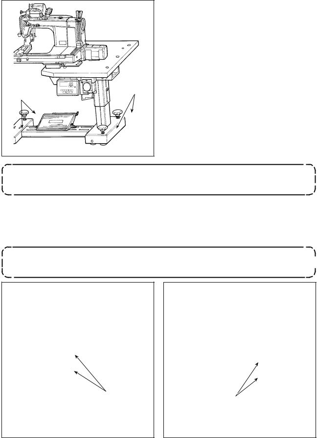
2-1. Setting up the sewing machine
Fix the sewing machine on the floor with adjuster bolts (four pieces).
|
|
|
Be sure to move the sewing machine with two or more persons.
2-1-1. Adjusting the sewing machine head
Loosen bolts (four pieces) and adjust the height of sewing machine.
1. Total weight of the sewing machine, machine table and control box is 110 kg or more. It is necessary to adjust the sewing machine height with four or more persons. 
2. Adjust the sewing machine height so that it is levelled.
|
|
|
– 2 –
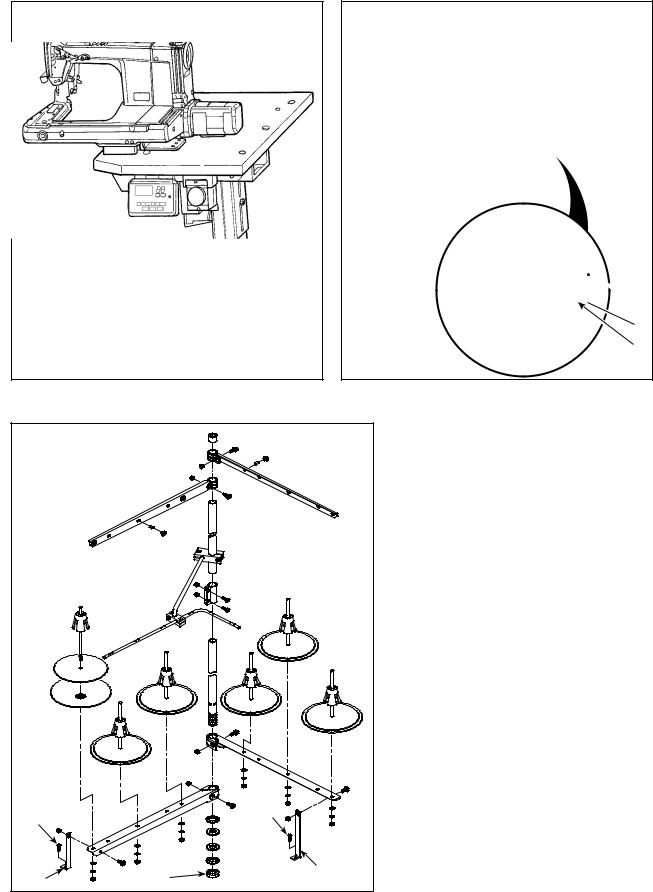
2-1-2. Changing the position of the operation panel
The operation panel has been installed on the undersurface of the sewing machine table at the time of delivery. When you install it on the top surface of the sewing machine table, it is necessary to pass panel cord through hole in the lower section of motor cover .
At the time of shipment |
In the case of changing the position of the operation |
||
(undersurface of the sewing machine table) |
panel to the top surface of the sewing machine table |
||
|
|
|
|
|
|
|
|


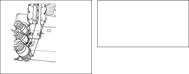
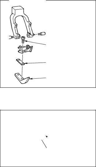
2-2. Installing the thread stand
|
|
|
|
|
|
|
|
|
|
||
|
|
– 3 – |
1)Assemble the thread stand device. Fit it
in the hole in the table. Tighten locknut
so that the thread stand does not fluctuate.
2)Fix thread stand bracket on the table with wood screw .
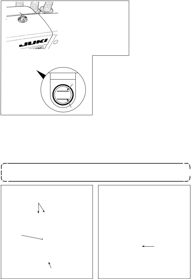
2-3. Oiling and draining of oil
Before putting your sewing machine into use, fill the oil tank with the oil supplied with the sewing machine.
|
|
1) Feeding oil |
|
||
|
|
Detach oil sight window . |
|
Put JUKI New Defrix Oil |
|
|
|
|
|
|
No. 1 or JUKI CORPORA- |
|
|
TION GENUINE OIL 7 into |
|
|
the oil tank through the oil |
|
|
hole. |
|
|
|
|
|
|
Fill the oil tank with the aforementioned oil until the oil surface reaches between two indicator lines (upper marker line A and lower marker line B). After filling the oil tank, be sure to fit oil sight
Awindow back to its home position.
H
L
B
2)Draining the oil and changing the oil
Firstly, loosen wood screws (three pieces). Detach oil tank cover . Then, loosen screw . Discharge the oil remaining in the oil tank completely. After discharging the oil, be sure to tighten screw .
In order to increase durability of the sewing machine, it is recommended to change the oil with new oil after the first four weeks have passed since the first use of the sewing machine, then carry out an oil change at an appropriate interval.
The waste oil must be disposed of properly according to the relevant laws and regulations in your area. 
– 4 –
3. PREPARATION BEFORE SEWING
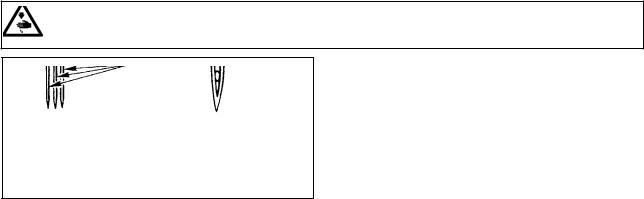
3-1. Attaching the needle
WARNING :
Turn OFF the power before starting the work so as to prevent accidents caused by abrupt start of the sewing machine.
Long
groove
Make a choice of the needle count in accordance with thickness of the thread and type of the material to be used.
1)Turn the hand wheel until the needle bar reaches to the highest position of its stroke.
2)Loosen screw in the needle clamp, and turn needles so that the long groove on the respective needles is brought in front of you.
3)Insert the needles into the needle clamp hole until they will go no further.
4)Securely tighten needle clamp screw .
– 5 –

3-2. Threading the machine head
WARNING :
Turn OFF the power before starting the work so as to prevent accidents caused by abrupt start of the sewing machine.
a
b
c
MA-1261A
b
a
c
MA-1261AM
b
|
|
|
|
a' |
c |
|
c |
|
|
|
|
|
|
|
|
|
a |
b' |
c' |
|
b |
|
|
|
a |
b |
|
||
|
|
|
||
|
|
|
|
b' |
|
a' |
c' |
|
a'
c'
b'
a'
|
|
|
b' |
|
|
|
c' |
|
b' |
b' |
|
|
a'
a' |
c' |
c' |
|
c |
a |
|
|
||
|
Pass the needle thread on the sewing machine head in numerical order form . Pass the looper thread on the sewing machine head in numerical order from .
a = Right-hand needle thread |
b = Intermediate needle thread |
c = Left-hand needle thread |
a' = Right-hand looper thread |
b' = Intermediate looper thread |
c' = Left-hand looper thread |
– 6 –
3-3. Adjusting the thread tension
1) Adjusting the needle thread tension |
2) Adjusting the looper thread tension |

Turn thread tension nut clockwise to increase or counterclockwise to reduce the needle thread tension.
Turn tension adjusting screw clockwise to increase or counterclockwise to reduce the looper thread tension.
– 7 –
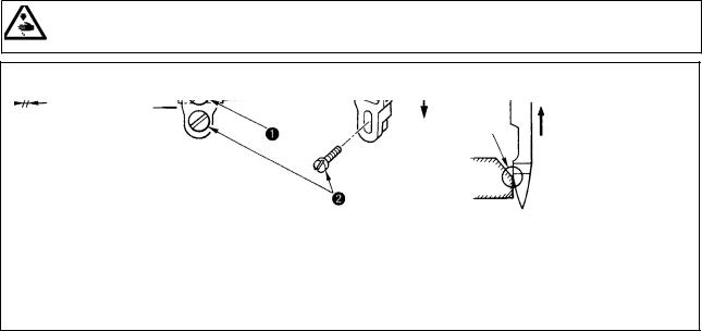
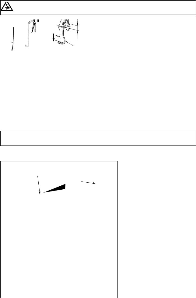
3-4. Adjusting the stitch length
WARNING :
Turn OFF the power before starting the work so as to prevent accidents caused by abrupt start of the sewing machine.
For the stitch length, adjust it on the sewing machine alone. Then, adjust the feed amount of the cloth puller belt. Then, finely adjust the stitch length while visually checking the finished state of sewing material.
■Adjusting the stitch length of the sewing machine alone
1)Remove screw , and loosen the lock screw in the feed rock cam.
|
2) Lightly pressing push-button , turn the hand- |
|
wheel by hand. |
|
3) When push-button bites, the sewing machine |
|
will stop running. |
|
4) In the aforementioned state, further pressing the |
|
push-button , turn the handwheel by hand. |
|
5) Aligning the marker dot (to be used for reference) |
|
on the handwheel with marker line on the tim- |
|
ing belt cover, release your hand from push-button |
|
. |
|
6) Tighten the lock screw in the feed rock cam. |
|
7) Attach screw in place. |
|
1. Never press the push-button while |
|
the sewing machine is in operation. |
|
2. Be sure to operate the sewing machine |
|
after tightening the lock screw. |
|
3. Never operate the machine with screw |
|
removed. |
|
4. The lock screw has a locking setscrew |
|
to prevent the screw from loosening. |
|
The lock screw head can be damaged |
|
if you forcefully remove it. |
Marker dot on the |
|
|
|
|
handwheel |
||||
|
|
|
||
Stitch length |
2 |
3 |
4 |
*The aforementioned marker dot is only a reference. Be aware that the adjustment result may differ with the material used.
– 8 –
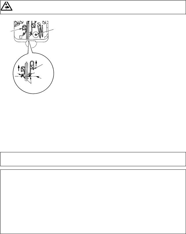
3-5. Adjusting the needle guard
WARNING :
Turn OFF the power before starting the work so as to prevent accidents caused by abrupt start of the sewing machine.
Press the section below
the needle
MS-1261A : eyelet.
0.1 0.15mm
MS-1261AM :
0.05 0.1mm
The needle guard has been mounted on the feed dog. It therefore necessary to adjust the needle guard whenever the feed amount is changed.
(Adjusting the clearance provided between the needle and the looper)
1)Turn the hand wheel to make the top end of the looper align with the center of the needle.
2)Loosen screw , move the entire unit of the needle guard to the right or left to make the needle guard press the needle so that the clearance of 0.1 to 0.15 mm is provided between the looper and the needle.(0.05 to 0.1 mm for MS-1261AM)
(Adjusting the vertical position of the needle guard)
1)Turn the handwheel to bring the needle guard at a position where the needle guard starts pressing the needle.
2)Loosen screw , and move the entire unit of the needle guard up or down so that the needle guard is located at a position where it does not press and deform needle thread loops (just below the needle eyelet).
(Adjusting the clearances between the respective needles and loopers)
If the clearances between the respective loopers and needles are not equal after the clearance between each needle and looper has been adjusted by moving the entire unit of the needle guard, adjust so that the equal clearance is provided between the respective loopers and needles following the steps described below.
1)Turn the handwheel to make the top end of the looper align with the center of the needle.
2)Loosen screw , move the respective needle guards to adjust so that the equal clearance is provided between the respective needles and loouers.
– 9 –
3-6. Adjusting the looper thread cam
WARNING :
Turn OFF the power before starting the work so as to prevent accidents caused by abrupt start of the sewing machine.
|
|
|
|
|
|
|
|
|
Loosen screw , and adjust looper thread cam |
|
|
|
|
so that the looper starts drawing the thread when it |
|||||
|
|
starts returning to its home position after it has pro- |
|||||||
|
|
|
|
|
|
|
|
|
|
|
|
|
|
|
|
|
|
|
jected the most. |
|
|
|
|
|
|
|
|
|
■ Adjusting the looper thread cam thread guide |
|
|
|
|
|
|
|
1) Align the end face of thread guide to the marker |
||
|
|
|
|
|
|
|
|
line on thread guide . Then adjust thread guide |
|
|
|
|
|
|
|
|
|
|
so that its end face is flush with the end face of |
|
|
|
|
|
|
|
|
|
thread guide . |
|
|
|
|
|
|
|
|
|
The standard position of the thread guide is ob- |
|
|
|
|
|
|
|
|
|
tained when the end face of the thread guide is |
|
|
|
|
|
|
aligned with the center marker line. |
|||
|
|
|
|
|
|
|
|
2) When using a cotton thread, loosen screws |
|
|
|
|
Position of the looper thread |
||||||
|
|
can for cotton thread |
|
and , and align the end faces of thread guides |
|||||
|
|
|
|
||||||
|
|
|
|
|
|
|
|
and to the marker line located far side. At |
|
|
|
|
|
|
Standard position |
||||
|
|
|
|
|
|
of the looper thread |
|
this time, it is not necessary to re adjust the looper |
|
|
Align the marker line with |
|
|
|
|
||||
|
|
|
cam |
|
|||||
|
the bottom end of the |
|
|
|
|
|
thread cam timing. |
||
|
|
|
|
||||||
|
|
thread guide. |
|
|
|
|
|
||
|
|
|
|
|
|
|
|
||
|
|
|
|
|
|
|
|
|
|
3-7. Adjusting the feed dog height
WARNING :
Turn OFF the power before starting the work so as to prevent accidents caused by abrupt start of the sewing machine.
1.4mm
|
|
|
|
|
|
|
|
|
Throat plate |
|
|
||
|
|
|
|
|
|
|
|
|
|
|
|
|
|
Feed dog |
|
|
|
Lower |
||
|
|
|
Higher |
|||
|
|
|
|
|
|
|
|
|
|
|
|
|
|
|
|
|
|
|
|
|
The top end of the feed dog should rise 1.4 mm above the surface of the throat plate when the feed dog is in the highest position of its stroke.
■ Adjusting the feed dog height
1)Loosen screw in the side plate of the bed and remove it.
2)Remove the screw , and loosen a hexagon socket head screw under the screw with an L-shaped hexagon wrench key.
3)Adjust the feed dog height by turning feed driving amount adjusting shaft .
4)Fix the shaft with the hexagon socket head screw and tighten screw .
–10 –
3-8. Adjusting the take-up thread tension control lever
WARNING :
Turn OFF the power before starting the work so as to prevent accidents caused by abrupt start of the sewing machine.
|
|
|
|
Needle thread loop size is determined |
|
|
|
|
by adjusting the position of take-up |
|
|
|
|
thread tension control lever . |
|
|
|
The needle thread loop size changes |
|
|
|
|
|
|
|
|
|
MS-1261A |
in accordance with the thread and |
|
Lowest |
|
: 3 mm |
material used. So, adjust the thread |
|
point dead |
|
MS-1261AM |
loop size upon occasion. |
|
|
: 0 mm |
||
Needle |
|
|
1) Loosen two screws , and adjust |
|
|
|
the position of the thread take- |
||
thread loop |
|
|
|
|
|
|
|
|
up lever guide by moving it up or |
|
|
|
|
|
|
|
|
|
down. |
2)Adjust so that, when the needle bar is in the lowest dead point, the top end of the thread tension control lever is positioned 3 mm above the top end of thread hole in needle bar thread take-up lever . (0 mm for MS-1261AM)
3)Lowering thread tension control lever decrease the loop size. Lifting the lever increases it.
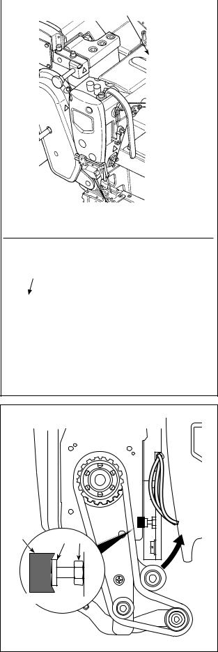
3-9. Adjusting the position of the intermediate tension release lever and needle thread tension controller
WARNING :
Turn OFF the power before starting the work so as to prevent accidents caused by abrupt start of the sewing machine.
Adjust the position of intermediate thread tension releasing lever and thread guide of the needle thread tension controller as described below.
|
|
|
|
|
1) Turn the handwheel to bring the nee- |
|
|
|
|
|
|
|
|
|
|
|
|
|
|
|
|
|
dle bar to the highest dead point. |
|
|
|
|
2) Remove rubber cap . Loosen |
|
|
|
|
|
|
|
|
|
|
|
setscrew locating under the rub- |
|
|
|
|
|
|
|
|
|
|
|
|
ber cap. Adjust intermediate thread |
|
|
|
|
|
tension release lever so that the |
|
|
|
|
|
thread coming out of intermediate |
|
|
|
|
|
needle thread guide is horizontal. |
|
|
|
|
|
3) Then, loosen two screws , and |
|
|
|
|
|
|
|
|
|
|
|
adjust the position of thread guide |
|
|
|
|
|
of the needle thread tension control- |
|
|
|
|
|
ler so that the thread coming from |
|
|
|
|
|
intermediate thread tension releasing |
|
|
|
|
|
lever makes a beeline. |
|
|
|
|
|
|
|
|
|
|||
|
|
|
|
||
Highest dead |
|
|
point |
|
|
– 11 –
3-10. How to adjust the cloth puller
3-10-1. Adjusting the cloth puller belt and its longitudinal position
|
1) Loosen hexagon head setscrews (three piec- |
|
|
||
es). |
||
|
Cloth puller belt
3 to
4mm
Feed dog of the sewing machine (largest feed pitch)
Maximize the feed amount of the main body of sewing machine. Adjust the feed amount to 3 to
4 mm by moving the cloth puller back and forth when the feed dog approaches closest to the belt.
Throat plate
|
|
|
|
Slightly sinks |
|
2)Loosen screw and adjust the longitudinal position of the cloth puller so that the head of screw comes in contact with rubber to such an extent that rubber slightly sinks.
3)Tighten nut to secure the cloth puller.
|
SM9051603SC |
Screw |
|
NM6050003SC |
Nut |
|
Cloth puller base |
Anti-vibration rubber |
|
binding part |
|
– 12 –
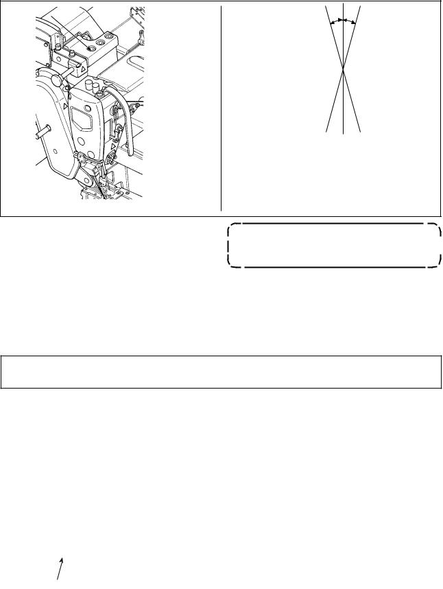
3-10-2. Adjusting the inclination of the cloth puller belt
θ
θ
1)Loosen hexagon head setscrews (two pieces). Rotate the cloth puller so that it is in parallel with the feed dog.
If the cloth puller inclines (as shown with θ), the chain-off thread skipping  may occur.
3-11. LED hand light
WARNING :
When adjusting the sensor, neither put your hand close to the needle entry area nor put your foot on the pedal in order to protect against injuries.
|
* This LED is intended to improve operability |
|
|
of the sewing machine and is not intended for |
|
|
maintenance. |
|
|
The sewing machine is provided as standard with an |
|
|
LED light which illuminates the needle entry area. |
|
|
Intensity adjustment and turn-off of the light is carried |
|
|
out by pressing switch . Every time the switch is |
|
|
pressed, the light is adjusted in intensity in five steps |
|
|
and is turned off in turn. |
|
|
[Change of intensity] |
|
|
1 |
...... 4 5 1 |
|
Bright |
...... Dim Off Bright |
|
In this way, every time the switch is pressed, the |
|
|
hand lamp status is changed in repetition. |
|
|
||
– 13 –
3-12. To use the sewing machine with a cloth puller for sewing heavy-to medium-weight materials
WARNING :
Turn OFF the power before starting the work so as to prevent accidents caused by abrupt start of the sewing machine.
The MS-1261A has been developed to sew extra heavy-weight materials as standard. Various kinds of gauges have been prepared to enable the machine to be used for sewing heavyto medium-weight materials. Replace the gauge, when sewing heavyto mediumweight materials, following the procedure described below.
3-12-1. Replacing the feed dog
3-12-2. Changing the throat plate
Remove the throat plate. Loosen screw in the feed dog and remove the feed dog. Then, replace the feed dog with an appropriate one.
Each of the feed dogs for heavyto medium-weight materials has been designed so that it can be used only by replacing it without adjusting the feed dog height. However, it is really necessary to adjust the feed dog height, refer to "3-7. Adjusting the feed dog height" p. 10
To change the height in difference on the righthand side of the feed dog
Loosen two serews in the adjusting feed dog and remove spacer (plate thickness: 0.5 mm).
Many different types of spacers are available.
Detach throat plate setscrews (two pieces) and(one piece). Then, change the throat plate with an appropriate one.
– 14 –
3-12-3. Adjusting the difference in height of the presser foot
(Standard L: 3.5 mm)
3-12-4. Replacing the needle thread guide


Remove two screws that are used to retain adjusting presser foot , and adjust the difference in height of the presser foot by replacing spacer . Thicknesses of spacers that match the respective throat plates and feed dogs are as shown in the
table. |
|
|
|
|
|
No. Plate |
Thickness |
Specification |
1 |
1.0mm |
Extra heavy-weight mate- |
|
|
rials (standard) |
2 |
0.5mm |
Heavy-weight materials |
3 |
None |
Medium-weight materials |
To replace spacer with a spacer (0.5 mm or none), replace screw with a shorter one (L=3.0 mm SS5060310SP).
When sewing a medium-weight material using a thin thread, larger needle thread loops will be produced and they will be likely to tilt causing stitch skipping. To prevent the aforementioned trouble, replace thread guide located above the needle clamp with an appropriate one.
Loosen screw that is used to fix thread guide , and replace the thread guide with thread guide for medium-weight materials.
– 15 –
– 16 –
3-13. Table of replaceable gauges
|
|
|
Part name |
|
Needle clamp (asm.) |
|
Throat plate |
|
Presser foot (asm.) |
|
Feed dog |
|
Needle thread guide |
|||||||
|
|
|
|
|
|
(with finger guard) |
|
|
||||||||||||
|
|
|
|
|
|
|
|
|
|
|
|
|
|
|
|
|
|
|||
|
|
Needle gauge |
|
|
|
|
|
|
|
|
|
|
|
|
|
|
||||
Model |
Application |
|
|
|
|
|
|
|
|
|
|
|
|
|
|
|
|
|
|
|
Code |
|
inch |
|
mm |
|
|
|
|
|
|
|
|
|
|
|
|
|
|
||
|
|
|
|
|
|
|
|
|
|
|
|
|
|
|
|
|
|
|||
|
|
|
|
|
|
|
|
|
|
|
|
|
|
|
|
|
|
|
|
|
MS-1261A |
Extra-heavy-weight materials |
F |
|
1/4 |
|
6.4 |
12956256 |
|
|
40202942 |
|
40202943 |
|
12963351 |
|
|
||||
MS-1261A |
Heavy-weight materials |
F |
|
1/4 |
|
6.4 |
12956256 |
|
|
40204587 |
|
40204601 |
|
12974150 |
|
|
||||
MS-1261AM |
Medium-heavy-weight materials |
F |
|
1/4 |
|
6.4 |
12956256 |
|
|
40204592 |
|
40205581 |
|
12974952 |
|
B1130051000 |
||||
|
|
|
|
|
|
|
|
|
|
|
|
|
|
|
|
|
||||
|
|
|
Part name |
|
Looper (L) (asm.) |
|
|
Looper (R) (asm.) |
|
|
Looper (C) (asm.) |
|
|
|||||||
|
|
Needle gauge |
|
|
|
|
Mark |
|
|
|
Mark |
|
|
|
||||||
|
|
|
|
|
|
|
|
|
|
|
|
|
|
|
|
|||||
Model |
Application |
|
|
|
|
|
|
|
|
|
|
|
|
|
|
|
|
|
|
|
Code |
|
inch |
|
mm |
|
|
Mark |
|
|
|
|
Mark |
|
|
|
|
Mark |
|
||
|
|
|
|
|
|
|
|
|
|
|
|
|
|
|
||||||
|
|
|
|
|
|
No. |
|
|
|
|
No. |
|
|
|
|
No. |
|
|||
|
|
|
|
|
|
|
|
|
|
|
|
|
|
|
|
|
|
|||
|
|
|
|
|
|
|
|
|
|
|
|
|
|
|
|
|
|
|
||
MS-1261A |
Extra-heavy-weight materials |
F |
|
1/4 |
|
6.4 |
12968558 |
|
1 |
|
12968855 |
|
1 |
|
12969150 |
|
1 |
|
||
MS-1261A |
Heavy-weight materials |
F |
|
1/4 |
|
6.4 |
12968558 |
|
1 |
|
12968855 |
|
1 |
|
12969150 |
|
1 |
|
||
MS-1261AM |
Medium-heavy-weight materials |
F |
|
1/4 |
|
6.4 |
12968558 |
|
1 |
|
12968855 |
|
1 |
|
12969150 |
|
1 |
|
||
Options
|
1. Spacer for presser foot |
2. Setscrews |
|||
No. |
Plate thickness (mm) |
Part No. |
Part name |
Part No. |
Plate |
|
0.3 |
12973509 |
Presser foot adjusting plate B |
SS5060310SP |
2 |
|
0.5 |
12973608 |
Presser foot adjusting plate C |
2 |
|
|
0.8 |
12973707 |
Presser foot adjusting plate D |
|
2 |
|
1.0 |
12962106 |
Presser foot adjusting plate A |
SS5060410SP |
2 |
|
1.2 |
12973806 |
Presser foot adjusting plate E |
|
2 |
3. Spacer for feed dog
No. |
Plate thickness (mm) |
Part No. |
Part name |
|
0.3 |
12975702 |
Feed dog adjusting plate B |
|
0.5 |
12964102 |
Feed dog adjusting plate A |
|
0.8 |
12975801 |
Feed dog adjusting plate C |
|
1.0 |
12975900 |
Feed dog adjusting plate D |
Folder |
|
|
|
|
|
|
|
|
|
|
1 |
2 |
3 |
Code of folder |
|
Part name |
|
|
Folder (asm.) |
|
M297 |
— For medium-weight materials |
|
|
|
|
M297 |
M298 |
M299 |
|
(Equipped on MS-1261AM as standard) |
Needle gauge |
|
|
|
M298 |
— For heavy-weight materials (Optional) |
||
|
|
|
|
|
|
M299 |
— For extra-heavy-weight materials |
Code |
inch |
mm |
|
|
|
|
(Equipped on MS-1261A as standard) |
|
|
|
|
|
|||
F |
1/4 |
6.4 |
MAM2970EEBA |
MAM2980BBBA |
MAM2990BBBA |
|
|
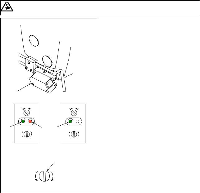
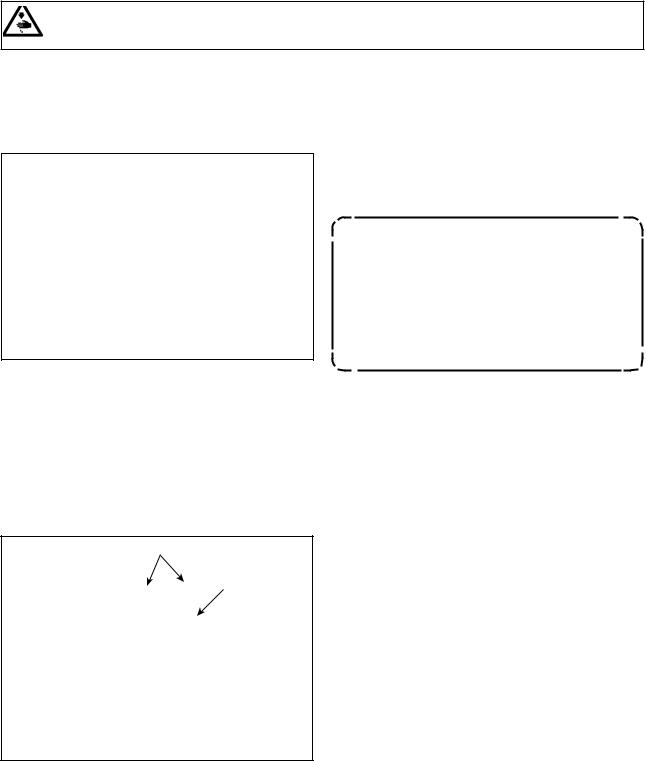
3-14. Adjusting the material edge detector
WARNING :
When adjusting the sensor, neither put your hand close to the needle entry area nor put your foot on the pedal in order to protect against injuries.
|
|
|
|
|
L |
D |
|
L |
D |
A |
min |
B |
A |
min |
max |
|
max |
||
Material is |
|
Material is |
||
present |
|
absent |
||
|
|
|
|
|
|
min |
|
max |
|
Material edge detector detects the presence / absence of the material at the beginning and end of sewing.
When the material is present, the green LED (A) and the orange LED (B) light up at all times.
When the material is absent, only the green LED (A) lights up.
The detecting device of the sewing machine has been factory-adjusted at the time of shipment so that it detects the presence / absence of the material without additional adjustment. However, the detecting device may fail to detect the material properly depending on the type of material used.
In such a case, adjust the detecting device of the sewing machine by turning control knob .
[Adjustment procedure]
* The orange LED (B) lights up even when the material is not present on the sewing machine.
→ Turn control knob toward the "min".
*The orange LED (B) goes out even when the material is present on the sewing machine.
→ Turn control knob toward the "max".
– 17 –
3-15. Needle cooler
3-15-1. Adjusting the position of the blow pipe
1) Loosen screw .
2) Adjust the position of blow pipe in terms of the longitudinal direction and rotational direction.
3) Tighten screw to secure blow pipe .


3-15-2. Adjusting the air flow
Adjust the air flow of the needle cooler by turning speed controller knob . Turn the speed controller knob clockwise to decrease the air flow or counterclockwise to increase it.
3-16. Chain-off thread cutter (suction of thread waste)
|
To |
To |
|
decrease |
increase |
||
|
Adjust the air flow of the needle cooler by turning speed controller knob . Turn the speed controller knob clockwise to decrease the air flow or counterclockwise to increase it.
– 18 –
4. HOW TO USE THE OPERATION PANEL
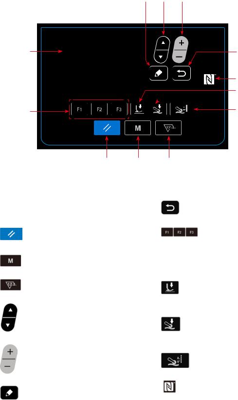
4-1. Explanation of the operation panel switch
|
|

|
|
No. |
NAME |
FUNCTION |
|
LCD display |
Various data such as pat- |
|
|
tern No., shape, etc. are |
|
|
displayed. |
|
RESET key |
Press this key to reset |
|
|
the error or reset the |
|
|
counter(s), etc. |
|
MODE key |
This key is used for dis- |
|
|
playing the mode screen. |
|
|
|
|
COUNTER key |
This key selects counter |
|
|
display. |
|
|
|
|
ITEM SELECT key |
This key is used to select |
|
|
the data No. and other |
|
|
kinds of data. |
|
|
|
|
DATA CHANGE key |
This key is used to change |
|
|
the pattern No. and other |
|
|
kinds of data. |
|
|
|
|
EDIT key |
This key is used to display |
|
|
the edit screen, to select |
|
|
the item or to display the |
|
|
detail screen. |
No. |
NAME |
FUNCTION |
|
RETURN key |
This key is used to return |
|
|
the screen to the previous |
|
|
one. |
|
F key |
When data or function is |
|
|
registered to the F key, |
|
|
the registered data or the |
|
|
function can be used by |
|
|
pressing the F key. |
|
Presser foot pres- |
Sewing data about the |
|
sure key |
presser foot pressure is |
|
|
displayed by pressing this |
|
|
key. |
|
Cloth puller pressure |
Sewing data about the |
|
key |
cloth puller pressure is |
|
|
displayed by pressing this |
|
|
key. |
|
Cloth pulling amount |
Sewing data about the |
|
key |
cloth pulling amount is |
|
|
displayed by pressing this |
|
|
key. |
|
|
|
|
NFC mark |
Bring the tablet or smart- |
|
|
phone close to the NFC |
|
|
mark when carrying out |
|
|
communication. |
– 19 –
4-2. Operation to be done at first
4-2-1. Selection of the language
Select the language to be displayed on the operation panel when you turn ON the power to your sewing machine for the first time after the purchase. Note that, if you turn the power OFF without selecting the language, the language selection screen will be displayed every time you turn ON the power to the sewing machine.
Turning ON the power switch
Be aware that the needle bar moves automatically when you turn ON the power to the sewing machine for the first time after the purchase. It is also possible to prevent the needle bar from moving automatically using the memory switch U090. Refer to "4-5-1. Memory switch data" p. 45 for details.
When you turn ON the power switch, the language selection screen is displayed.
<Language selection screen>
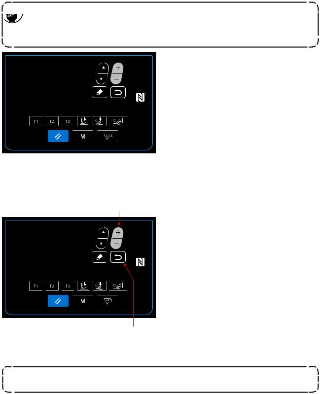
Selecting the language
Select the language you want to use for display with
 . Then, press
  to finalize your selection of the language.
The language to be displayed on the operation panel can be changed using the memory switch U406. Refer to "4-5-1. Memory switch data" p. 45 for details.
If you do not select your language for display, English will be used for display as default.
– 20 –

When you turn ON the power to the sewing machine, the sewing screen for the pattern that is currently selected is displayed.
This sewing machine is able to sew free sewing patterns and step sewing patterns. As many as 99 different sewing patterns can be created by combining free sewing patterns and step sewing patterns.
In the case of a free sewing pattern, different sewing conditions can be adopted respectively for sewing flat sections and multi-layered sections of material.
In the case of a step sewing pattern, separate sewing conditions can be adopted for sewing a material on a step-by-step basis.
The below-stated section of this Instruction Manual describes the free sewing patterns. Refer to "4-4-6. How to edit a step sewing pattern" p. 34 for the description about step sewing patterns.
|
|
|
|
|
|
|
C |
|||||
J |
|
|
|
|
|
|
|
|
|
|
|
I |
|
|
|
|
|
|
|
|
|
|
|
||
|
|
|
|
|
|
|
|
|
|
|
|
|
A |
|
|
|
|
|
|
|
|
|
|||
|
|
|
|
|
|
|
|
|||||
B |
|
|
|
|
|
|
|
|
|
|
G |
|
|
|
|
|
|
|
|
|
|
|
|||
|
|
|
|
|
|
|
|
|
|
|
|
H |
|
|
|
|
|
|
|
|
|
|
|
|
|
|
|
|
|
|
|
|
|
|
|
|
|
|
D |
E |
F |
|
|
|
|||
|
|
Sewing screen <Free sewing pattern> |
|
|
|
|||||
|
|
|
|
|
|
|
|
|
|
|
|
Display |
|
|
|
|
|
Content |
|
|
|
|
|
|
|
|
|
|
||||
A |
Pattern No. |
Pattern No. that is being selected is displayed. (No. 1 to No. 99) |
|
|||||||
B |
Cloth pulling amount *1 |
Cloth pulling amount is displayed. |
|
|
|
|||||
C |
Cloth puller pressure *1 |
Cloth puller pressure is displayed. |
|
|
|
|||||
D |
Sewing speed *1 |
Sewing speed is displayed. |
|
|
|
|||||
E |
Stitch length *3 |
Stitch length set with the memory switch S003 is displayed. |
|
|
||||||
F |
Presser foot pressure *1 |
Presser foot pressure is displayed. |
|
|
|
|||||
G |
State of the material |
State of the material placed under the cloth puller is displayed. |
|
|||||||
|
under the cloth puller |
Top end of |
Flat section |
Multi-layered |
No material |
Cloth puller is |
|
|||
|
|
material |
section begins |
not used |
|
|||||
|
|
|
|
|
|
|
||||
H |
State of the material |
State of the material placed under the presser foot is displayed. |
|
|||||||
|
under the presser foot |
Top end of |
|
|
Multi-layered |
During the |
End of the |
No ma- |
||
|
|
|
|
multi-layered |
multi-layered |
|||||
|
|
Flat section |
section be- |
|||||||
|
|
material |
section of mate- |
section of mate- |
terial |
|||||
|
|
|
|
|
gins |
|||||
|
|
|
|
|
|
|
rial |
rial |
|
|
|
|
|
|
|
|
|
|
|
||
|
|
|
|
|
|
|
|
|
||
I |
Simple-locked state |
ON / OFF of the simple lock is displayed. |
|
|
|
|||||
J |
Part number / process or |
Part number is displayed on the upper line and the process is displayed on the low- |
||||||||
|
comment |
er line. Or, comment is displayed on two lines (upper and lower lines). (Content of |
||||||||
|
|
display, i.e., the "part number and process" or the "comment", can be changed over |
||||||||
|
|
with the memory switch U404. Refer to "4-5-1. Memory switch data" p. 45 for |
||||||||
|
|
details). |
|
|
|
|
|
|
|
|
– 21 –
Loading...