


 Loading...
ENGLISH
SC-910N
Instruction Manual
|
CONTENTS |
|
!. SPECIFICATIONS...................................................................................... |
1 |
|
@. SET-UP....................................................................................................... |
1 |
|
1. |
Installing M91 small sized motor unit................................................................................................ |
1 |
2. |
Installing to the table........................................................................................................................... |
2 |
3. |
Adjusting the belt (when M91 is used).............................................................................................. |
2 |
4. |
Adjusting the belt cover (when M91 is used).................................................................................... |
3 |
5. |
Connecting the cords.......................................................................................................................... |
4 |
6. |
Attaching the connecting rod........................................................................................................... |
11 |
7. |
Setting procedure of the machine head.......................................................................................... |
12 |
8. |
Machine head list............................................................................................................................... |
13 |
9. |
Adjusting the machine head (DDL-9000A only).............................................................................. |
14 |
#. FOR THE OPERATOR............................................................................. |
15 |
|
1. |
Operating procedure of SC-910N..................................................................................................... |
15 |
2. |
Explanation of the operation panel.................................................................................................. |
17 |
3. |
Operating procedure of the sewing pattern.................................................................................... |
18 |
|
(1) Reverse stitching pattern............................................................................................................... |
18 |
|
(2) Overlapped stitching pattern......................................................................................................... |
19 |
|
(3) Special setting............................................................................................................................... |
20 |
4. |
Setting for functions of SC-910N..................................................................................................... |
22 |
5. |
Function setting list.......................................................................................................................... |
24 |
6. |
Detailed explanation of selection of functions............................................................................... |
31 |
7. |
Automatic compensation of neutral point of the pedal sensor ................................................... |
40 |
8. |
Selection of the pedal specifications.............................................................................................. |
40 |
9. |
Setting of the auto lifter function..................................................................................................... |
41 |
10. |
Connection of the pedal of standing-work machine...................................................................... |
41 |
11. |
External input / output connector.................................................................................................... |
42 |
12. |
Connection of the material end sensor (ED)................................................................................... |
42 |
13. |
Initialization of the setting data........................................................................................................ |
43 |
$. MAINTENANCE....................................................................................... |
44 |
|
1. |
Removing the rear cover.................................................................................................................. |
44 |
2. |
Replacing the fuse............................................................................................................................ |
44 |
3. |
Error codes........................................................................................................................................ |
45 |
i

!. SPECIFICATIONS
Supply voltage |
Single phase 100 to 120V |
3-phase 200 to 240V |
Single phase 200 to 240V |
Frequency |
50Hz/60Hz |
50Hz/60Hz |
50Hz/60Hz |
Operating envi- |
Temperature : 0 to 40˚C |
Temperature : 0 to 40˚C |
Temperature : 0 to 40˚C |
ronment |
Humidity : 90% or less |
Humidity : 90% or less |
Humidity : 90% or less |
Input |
350VA |
350VA |
350VA |
@. SET-UP
SC-910N control box can be used for DD (direct-drive) system machine head and the belt-drive system machine head by connecting the separately-available small-sized motor unit (M91).
When using the small-sized motor unit, it is necessary to install the motor unit to the control box before installing the control box to the table.
Install the motor unit to the control box following the instructions below.
SC-910N control box |
M91 small-sized motor unit (separately-available article) |
A
1. Installing M91 small sized motor unit
2
1
1)Lay down the control box while the rear cover is placed under the control box.
2)Remove tie-mount A.
3)Adjust the hole section of the installing base of M91 to the hole section of the installing plate.
4)Temporarily tighten five places with counter-sunk screws 1 supplied with the unit as accessories.
5)Securely tighten them with hexagonal wrench key 2 supplied with the unit as accessories.
(Caution) 1. When tightening the screw, securely insert the hexagonal wrench key into the screw hole section to tighten.
2.Hexagonal wrench key is attached to M91.
3.Be careful that the motor shaft does not hit against anything. (If a strong shock is given to the motor shaft, there is the possibility that the motor is damaged.)
ENGLISH
––

2. Installing to the table
1) Install the control box to the table with the fitting bolt (asm.) supplied with the unit as accessories. At this time, insert the nut and washer supplied with the unit as accessories as shown in the figure so that the control box is securely fixed.
Plain washer
Spring washer
Hexagonal nat
2)Set the machine head to the table after installing the control box (or with small-sized motor) to the table. (Refer to Instruction Manual for the sewing machine.)
3. Adjusting the belt (when M91 is used)
1) Adjust the belt tension by turning upper and lower nuts 1 of the adjustment bolt and adjusting the height of the center of the motor so that the belt sags 15 mm (9.8N) when the center of the belt is pressed by hand.
(Caution) 1. When the belt tension is excessively low, medium or low speed rotation becomes uneven, or stop accuracy is deteriorated. When the tension is excessively high, deterioration of the motor is advanced. So, be careful.
––
4.Adjusting the belt cover (when M91 is used)
1)Adjusting the clearance of the cover
Loosen cover setscrew 1 and adjust so that the left and right clearances between the belt cover and the belt are equal to each other.
(Caution) 1. Perform the adjustment of the cover with the hexagonal wrench key supplied with the unit as accessories. At this time, be careful that the screw is not excessively loosened.
1
4mm
2
3mm
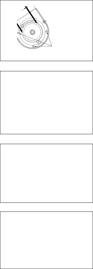
2) Adjusting the roll-in prevention pin
Adjust the roll-in prevention pin with the hexagonal wrench key supplied with the unit as accessories so that the clearance between the belt and roll-in prevention pin 2 is approximately 4 mm.
(Caution) 1. Be careful of the direction of rotation of the motor and determine the position of the pin. (Position shown in the figure is the installing position when the motor rotates in the direction of the arrow mark.)
2.Perform the adjustment of the cover with the hexagonal wrench key supplied with the unit as accessories. At this time, be careful that the screw is not excessively loosened.
3)Adjusting the off-belt prevention pin
Adjust the off-belt prevention pin with the hexagonal wrench key supplied with the unit as accessories so that the clearance between the belt and off-belt prevention pin 3 is approximately 3 mm.
(Caution) 1. Perform the adjustment of the cover with the hexagonal wrench key supplied with the unit as accessories. At this time, be careful that the screw is not excessively loosened.
4)Installing the belt cover
Adjust the notch section of the pulley outer cover 4 to the gap of screw 5 of the pulley inner cover and insert the outer cover to the inner cover.
5)Tighten screw 5 to complete the adjustment of the cover.
4
ENGLISH
––

5. Connecting the cords
WARNING :
• To prevent personal injury caused by abrupt start of the sewing machine, carry out the work after turning OFF the power switch and a lapse of 5 minutes or more.
• To prevent damage of device caused by maloperation and wrong specifications, be sure to connect all the corresponding connectors to the specified places.
• To prevent personal injury caused by maloperation, be sure to lock the connector with lock.
• As for the details of handling respective devices, read carefully the Instruction Manuals supplied with the devices before handling the devices.
|
7 |
|
|
|
6 |
Optional unit A |
3 |
|
|
4 |
|
8 |
|
|
|
1 |
2 |
|
|
|
5 |
||
|
9 |
|
|
|
|
6 |
|
!1 |
|
1 |
|
|
|
|
|
|
2 |
9 |
7 |
|
|
|
8 |
|
5 |
|
|
|
!3 |
|
|
3
4 !0 !2
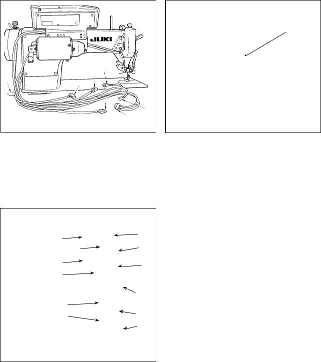
Following connectors are prepared on the front face of SC-910N. Connect the connectors coming from the machine head to the corresponding places so as to fit the devices mounted on the machine head.
1 CN30 Synchronizer : it detects the needle bar position.
2 CN35 CP-170 panel : Various kinds of programmed sewing can be executed. (Refer to the Instruction Manual for each panel for the details of functions.)
3 CN31 Machine head connector 4P
4 CN42 External input/output connector : input/ output of up/down detection signal, rotation prohibition signal, etc. is prepared.
5 CN48 Safety switch (standard) : When tilting the sewing machine without turning the power OFF, the operation of the sewing machine is prohibited so as to protect against danger. Optional switch : by changing over the internal functions, 6 kinds of functions can be selected.
6 CN40 Presser foot lifter solenoid. (For automatic presser foot lifter type only)
7 CN46 Machine head solenid : Thread trimming, reversestitching solenoid, touch-back switch, etc.
8CN47 Optional circuit board connection connector
:Required when using JUKI standard bobbin thread remaining amount detection sensor, etc.
9 CN39 Motor signal connector
!0CN32 Standing machine pedal : JUKI standard PK-70, etc. Sewing machine can be controlled with the external signal.
!1CN34 IP-110 panel (LCD panel) : Various kinds of programmed sewing can be executed.
!2CN45 Material end detection sensor ED-5, etc. !3CN43 Fan
*By adding the optional unit A, the following optional devices of JUKI standard can be connected.
1 CN128 |
Left/right needle detection |
2 CN127 |
Thread holding, thread suction, thread |
|
drawing |
3 CN122 |
Needle cooler (bottom fan) |
4 CN121 |
Bobbin thread remaining amount detection |
5 CN120 |
+24V external power source |
6 CN123 |
Needle/bobbin thread remaining amount |
|
detection sensor |
7 CN125 |
External interface I/F D/A Input |
8 CN126 |
Left/right lock SW, LED |
9 CN129 |
Thread holding, thread suction, thread |
|
drawing, bobbin thread remaining amount |
|
detection. |
––
7
8
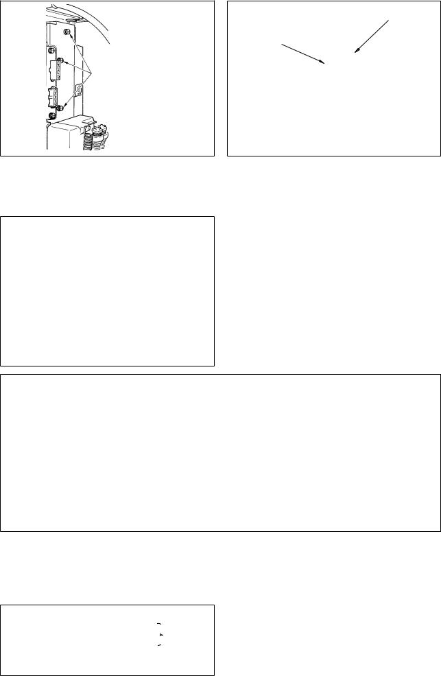
1)Pass the cords 1 of the thread trimming solenoid, reverse-stitching solenoid, etc., and the cords of the synchronizer 2, safety switch 3, machine head 4P connector 4, motor signal 5, motor output 6 through hole A in the table to route them down under the machine table.
2)Loosen setscrew 8 in front cover 7.
3)Pressing the side of front cover 7 in the direction of the arrow, open the front cover toward you.
Note : Be sure to open / close the front cover with your hands.
4) Connect 14P code 1 coming from the machine head to connector A (CN46).
95) Connect 4P connector coming from the machine
A |
|
head 4 to connector B (CN31). (It is not neces- |
|
|
|
||
F |
2 |
sary in case of DDL-9000A.) |
|
|
|
||
D |
3 |
6) Connect 4P connector 3 (safty switch connec- |
|
|
tor) coming from the machine head to connector |
||
E |
|
||
|
C (CN48). |
||
|
|
||
|
1 |
7) Connect 7P connector 2 coming from the ma- |
|
|
chine head to connector D (CN30).(It is not nec- |
||
C |
|
||
|
essary in case of DDL-9000A.) |
||
B |
4 |
||
8) Connect connector 5 coming from the machine |
|||
|
|||
|
5 |
||
|
head (motor) to connector E (CN39). |
||
|
|
||
|
|
9) When the optional AK138 device is attached, |
|
|
|
connect 2P connector 9 coming from the AK de- |
|
|
|
vice to connector F (CN40). |
(Caution) 1. When using the AK device, set whether to use the AK device after confirming how to select the auto-lifter function. (Refter to “#-9. Setting of the auto lifter function” p. 41.)
2.Be sure to securely insert the respective connectors after checking the inserting directions since all connectors have the inserting directions. (When using a type with lock, insert the connectors until they go to the lock.) The sewing machine is not actuated unless the connectors are inserted properly. In addition, not only the problem of error warning or the like occurs, but also the sewing machine and the control box are damaged.
ENGLISH
––

!0
!1
C
B
!4
10) Fix all cables coming from the machine head with cable clip band !0attached to tie-mount !1.
[ Connection of the connector for CP panel ]
Exclusive connectors are prepared for connection of the connector for CP-170.
Paying attention to the orientation of the connector, connect it to connector B located on the circuit board. After connecting, securely lock the connector.
[ Connecting for IP panel ]
The connector for connecting IP-110 is prepared. When connecting, insert the connector until it is locked to C.
11) After inserting the connector, put all cords together with cable clip band !2located on the side of the box.
At this time, bundle the connectors which are arranged above the wire saddle to wire saddle !3and those which are arranged below the wire saddle to wire saddle !4.
(Caution) 1. Fix the cord clamp and the cable clip band following the attaching procedure.
2.When removing the connector, remove it from the wire saddle and remove it while pressing the hook of the cable clip band.
––

How to fix cable clip band !2
Pull Pull
How to remove cable clip band
Push |
Push Push the hook. |
Pushing the hook portion, push the band to remove it.
8
D
7
(Caution) 1. Fix the cable clip band following the attaching procedure as shown in the figure.
2.To remove the cable clip band, push the cable clip band until it comes off while pressing the hook of the band following the removing procedure as shown in the figure.
12)Close front cover 7 while paying attention to pinching of the wire.
Lightly press portion D and insert front cover 7 with “click”.
13)After that, fix it with the screw 8.
14)Connect motor output cord 6 to connector G located on the side of the box. Connect connector 4P !5of the power switch to connector H.
(Caution) Route the motor output cord from the front face of the box.
G
ENGLISH
––
[For CE specifications only]
3
4
1
2
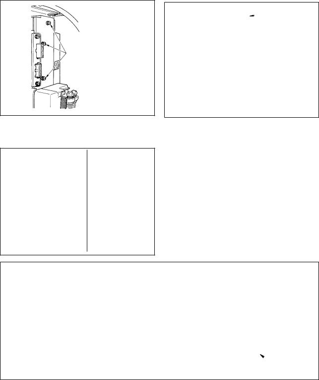
15)Remove three screws 1 located on the side of the control box.
6
7
5
16)Set power source cord set 3 and installing plate 4 supplied with the unit as accessories as shown in the figure, and fix them to the control
box main unit with three setscrews 2 which have been removed.
17)Connect connector 5 coming from the power source cord to lower connector 6 after checking the direction.
(Caution) When rubber bush 7 is off the installing plate, adjust it to the groove of the installing plate and insert it.
!1
9
!0
18)Connect motor output cord 8 to connector 9 located on the side of the box.
19)Fix power source cover !0supplied with the unit using two screws !1supplied with the unit.
(Caution) At this time, be careful so that the motor output cord is not caught by the power source cover and so that the cord enters the recess of the power source cover.
CE 1ø 230V
Brown |
|
AC |
|
||
Blue |
|
220V-240V |
|
Green / Yellow (ground wire)
20) Installing power switch
Connect power supply cord to the power switch.
[CE specifications]
Single phase 230V : Power supply cords : Brown, Blue, and green/yellow (ground wire)
––
[Power voltage changeover procedure (power voltage setting procedure)]
WARNING :
To prevent personal injuries caused by electric shock hazards or abrupt start of the sewing machine, carry out the work after turning OFF the power switch and a lapse of 5 minutes or more. To prevent accidents caused by unaccustomed work or electric shock, request the electric expert or engineer of our dealers when adjusting the electrical components.
It is adaptable to the voltage of single phase 100V to 120V/3-phase 200V to 240V by changing the voltage changeover connector mounted on FLT p.c.b.
(Caution) When the changing procedure is wring, the control box will be broken. So, be very careful.
1
A |
|
|
(Plug side) |
||
|
|
||||
|
|
|
|||
|
|
|
|||
WHITE |
WHITE |
|
|||
BLACK |
BLACK |
|
|||
RED |
RED |
|
|||
GREEN/ |
GREEN/ |
|
|||
YELLOW |
YELLOW |
|
|||
|
|
|
|
||
|
|
|
|
||
B |
|
|
|
|
|
|
|
|
|
||
WHITE |
WHITE (Plug side) |
||||
BLACK |
BLACK |
|
|||
RED |
RED |
|
|||
GREEN/ |
GREEN/ |
|
|||
YELLOW |
YELLOW |
|
|||
|
|
|
|
||
|
|
|
|
||
C |
|
|
|
(Plug side) |
|
|
|
|
|||
|
|
|
|
||
WHITE |
WHITE |
||||
|
|||||
BLACK |
BLACK |
|
|||
RED |
RED |
|
|||
GREEN/ |
GREEN/ |
|
|||
YELLOW |
YELLOW |
|
|||
Changing procedure of the changeover connector
1.Turn OFF the power source with the power switch after confirming that the sewing machine has stopped.
2.Draw out the power cord from the power plug socket after confirming that the power switch is turned OFF. Then wait for five minutes or more.
3.Remove the front cover.
4.Remove three screws fixing the rear cover of the control box and slowly open the rear cover.
A.In case of using with 3-phase 200V to 240V¥
• Changing the changeover connector
Connect to 200V the 100/200V changeover connector of FLT p.c.b. 1.
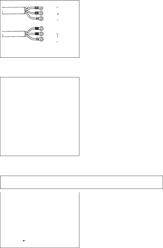
• Connect the crimp style terminal of AC input cord to the power plug as shown in the figure.
B.In case of using with single phase 100V to 120V
•Changing the changeover connector
Connect to 100V the 100/200V changeover connector of FLT p.c.b. 1.
•Connect the crimp style terminal of AC input cord to the power plug as shown in the figure.
(Caution) Securely perform the insulation treatment to the red terminal which is not used with insulation tape or the like. (When the insulation is insufficient, there is a danger of electric shock or leakage current.)
C. In case of using with single phase 200V to 240V
•Changing the changeover connector
Connect to 200V the 100/200V changeover connector of FLT p.c.b. 1.
•Connect the crimp style terminal of AC input cord to the power plug as shown in the figure.
(Caution) Securely perform the insulation treatment to the red terminal which is not used with insulation tape or the like. (When the insulation is insufficient, there is a danger of electric shock or leakage current.)
5.Check that the change has been performed without fail before closing the rear cover.
6.Be careful that the cord is not pinched between the rear cover and the control box main unit. Close the rear cover while pressing the lower side of rear cover, and tighten three screws.
[Point when inserting/drawing out the connector]
When it is difficult to remove the changeover connector, insert a small-sized screwdriver and press in the direction of the arrow as shown in the figure, and the connector can be removed with ease.
––
ENGLISH
[In case of using the power switch for LA]
It is necessary to separately purchase the parts below.
JUKI Part No. |
Description |
Q'ty |
Remarks |
40012006 |
Set A for LA |
1 |
For 3-phase 200 to 240V |
40012007 |
Set B for LA |
1 |
For single phase 100 to 120V |
In addition, separately prepare the power switch for LA.
 2
2
3
15) Remove three screws 1 located on the side of the control box.
7
5
6
4
16) Tighten cover installing fittings 2 to the control box main unit with three screws 3 which have been removed in step 15).
17) Connect connector 4 coming from the power source cord to lower connector 5 after checking the direction.
(Caution) Adjust rubber bush 6 to the groove of installing plate and insert it.
18) Pass nut 7 supplied with the power switch for LA through the power cord and insert the cord into the conduit (arrow mark).
Securely fix it to the installing fittings with nut 7 from both sides.
!1
 !0
!0
19)Connect motor output cord 8 to connector 9 located on the side of the box.
Fix power source cover !0supplied with the unit using two screws !1supplied with the unit.
(Caution) At this time, be careful so that the motor output cord is not caught by the power source cover and so that the cord enters the recess of the power source cover.
– 10 –
JA 3ø 220V |
Black |
|
|
|
|
AC |
|
|
Red |
|
|
|
|
||
|
|
200V-240V |
|
|
White |
|
|
|
|
|
Green / Yellow (ground wire) Black AC
White  100V-120V
Green / Yellow (ground wire)
@1
20) Installing power switch
Connect power supply cord to the power switch.
[JA specifications]
3-phase 220 V : Power supply cords : black, white, red and green/yellow (ground wire)
Single phase 120V : Power supply cords : black, white, and green/yellow (ground wire)
21) Make sure that the power switch is turned OFF and insert power supply cord @1coming from the power switch into the power plug socket. (Illustration is for the japanese specification 100V type.)
(Caution) 1. Top end of power supply cord @1 varies in accordance with destination or supply voltage. Check again the supply voltage and the voltage designated on the control box when installing the switch.
2.Prepare the power switch conformed to the safety standard.
3.Be sure to connect the ground wire ( green / yellow).
6. Attaching the connecting rod
WARNING :
To protect against possible personal injury due to abrupt start of the machine, be sure to start the following work after turning the power off and a lapse of 5 minutes or more.
|
|
1) |
Fix connecting rod 1 to installing hole B of ped- |
|
|
||
|
|
|
al lever 2 with nut 3. |
2) |
Installing connecting rod 1 to installing hole A |
||
|
|
|
will lengthen the pedal depressing stroke, and |
|
|
|
the pedal operation at a medium speed will be |
3 |
|
|
easier. |
|
A |
|
|
2
B
1
– 11 –

7. Setting procedure of the machine head
WARNING :
When the machine head other than DDL-9000A is used, the work of items 7, 8 and 9 is not necessary. The machine head is automatically selected by inserting the machine head connector.
1) Refer to "#-4. Setting for functions of SC910N" p.22, and call the function setting No. 95.
2) The type of machine head can be selected by pressing  switch 3 (
  switch 4).
34
3) After selecting the type of machine head, by pressing  switch 1 (
 switch 2), the step
proceeds to 96 or 94, and the display automatically changes to the contents of the setting corresponding with the type of machine head.
(Caution) When the type of machine head is changed, the contents which have been changed before return to the standard set values.
12
– 12 –
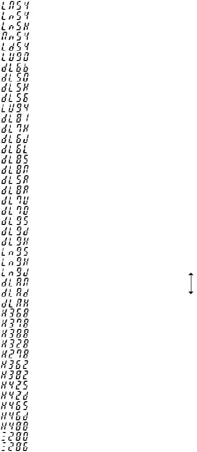
8. Machine head list
|
No. |
Machine head |
Contents |
Number of revolutions at |
Max. number of |
|
of display |
the time of delivery (rpm) |
revolutions (rpm) |
||
|
|
|
|||
|
|
|
|
|
|
|
1 |
DLM-5400 |
|
4000 |
4500 |
|
2 |
DLN-5410 |
|
4000 |
5000 |
|
3 |
DLN-5410H |
|
3500 |
4000 |
|
4 |
DMN-5420 |
|
4000 |
5000 |
|
5 |
DLD-5430 |
|
4000 |
4500 |
|
6 |
DLU-5490 |
|
4000 |
4500 |
|
7 |
DDL-5600B |
|
3700 |
4000 |
|
8 |
DDL-5550, DDL-8700 |
|
4000 |
5000 |
|
9 |
DDL-5550H |
|
3500 |
4000 |
|
10 |
DDL-5556 |
|
4000 |
4000 |
|
11 |
DLU-5494 |
|
3500 |
4000 |
|
12 |
DDL-5581 |
|
4000 |
5000 |
|
13 |
DDL-5571H |
|
3500 |
4000 |
|
14 |
DDL-5600J |
|
4000 |
4000 |
|
15 |
DDL-5600L, U, R |
|
3000 |
3000 |
|
16 |
DDL-5581S |
|
2000 |
3500 |
|
17 |
DDL-5581M |
|
4000 |
4000 |
|
18 |
DDL-5550A |
|
4000 |
4000 |
|
19 |
DDL-5581A, K |
|
4000 |
4000 |
|
20 |
DDL-5571U |
|
3500 |
3500 |
|
21 |
DDL-5700 |
|
4000 |
4000 |
|
22 |
DDL-9000S |
|
4000 |
5000 |
|
23 |
DDL-9000D |
|
4000 |
4000 |
|
24 |
DDL-9000H |
|
4000 |
4500 |
|
25 |
DLN-9010S |
|
4000 |
5000 |
|
26 |
DLN-9010H |
|
3500 |
4000 |
|
27 |
DLN-9010J |
|
3500 |
4000 |
* |
28 |
DDL-9000A SS/MA/MS |
|
4000 |
5000 |
|
29 |
DDL-9000A DS |
|
4000 |
4000 |
|
30 |
DDL-9000A SH |
|
4000 |
4500 |
|
31 |
LH-3168 |
|
3000 |
3000 |
|
32 |
LH-3178 |
|
3000 |
3000 |
|
33 |
LH-3188 |
|
3000 |
3000 |
|
34 |
LH-3128 |
|
3000 |
3000 |
|
35 |
LH-2178 |
|
4000 |
4000 |
|
36 |
LH-3162 |
|
3000 |
3000 |
|
37 |
LH-3182 |
|
3000 |
3000 |
|
38 |
LH-4128S |
|
3600 |
4000 |
|
39 |
LH-4128D |
|
3000 |
3000 |
|
40 |
LH-4168 |
|
3200 |
3200 |
|
41 |
LH-4168D |
|
3000 |
3000 |
|
42 |
LH-4188 |
|
3200 |
3200 |
|
43 |
LZ-2280 |
|
4000 |
5000 |
|
44 |
LZ-2286 |
|
4000 |
5000 |
Machine head set at the time of delivery
ENGLISH
– 13 –
Loading...