


 Loading...
SC-922
Instruction Manual
|
CONTENTS |
|
I. SPECIFICATIONS........................................................................................ |
1 |
|
II. SET-UP........................................................................................................ |
1 |
|
1. |
Installing to the table........................................................................................................................... |
1 |
2. |
Installing the motor unit...................................................................................................................... |
2 |
3. |
Installing the control box.................................................................................................................... |
2 |
4. |
Installing the belt................................................................................................................................. |
3 |
5. |
Adjusting the pulley cover.................................................................................................................. |
3 |
6. |
Installation and adjustment for the protecting pin and the belt slip-off preventing bracket....... |
4 |
7. |
Connecting the cords.......................................................................................................................... |
5 |
8. |
Attaching the connecting rod........................................................................................................... |
13 |
9. |
Setting procedure of the machine head.......................................................................................... |
14 |
10. |
Adjusting the machine head (direct-drive motor type sewing machine only)............................. |
15 |
III. FOR THE OPERATOR............................................................................. |
16 |
|
1. |
Operating procedure of the sewing machine................................................................................. |
16 |
2. |
Operation panel (CP-18).................................................................................................................... |
17 |
3. |
Operating procedure of the sewing pattern.................................................................................... |
18 |
|
(1) Reverse feed stitching pattern....................................................................................................... |
18 |
|
(2) Overlapped stitching pattern......................................................................................................... |
19 |
4. |
One-touch setting.............................................................................................................................. |
20 |
5. |
Production support function............................................................................................................ |
22 |
6. |
Setting of functions of SC-922 ........................................................................................................ |
25 |
7. |
Function setting list.......................................................................................................................... |
27 |
8. |
Detailed explanation of selection of functions............................................................................... |
33 |
9. |
Automatic compensation of neutral point of the pedal sensor ................................................... |
47 |
10. |
Selection of the pedal specifications.............................................................................................. |
47 |
11. |
Stitch alignment for the reverse stitching at the end of sewing (for heavy-weight materials).... |
48 |
12. |
Input/output function of the hand switch and knee switch........................................................... |
49 |
13. |
Use of the hand switch and the knee switch.................................................................................. |
50 |
14. |
Setting of the auto lifter function..................................................................................................... |
51 |
15. |
Selecting procedure of the key-lock function................................................................................. |
52 |
16. |
Initialization of the setting data........................................................................................................ |
52 |
17. |
External input / output connector.................................................................................................... |
53 |
18. |
How to connect the material edge sensor...................................................................................... |
54 |
IV. MAINTENANCE....................................................................................... |
55 |
|
1. |
Removing the rear cover.................................................................................................................. |
55 |
2. |
Replacing the fuse............................................................................................................................. |
55 |
3. |
Error codes........................................................................................................................................ |
56 |
I. SPECIFICATIONS
Supply voltage |
Single phase 100 to 120V |
3-phase 200 to 240V |
Single phase 220 to 240V |
Frequency |
50Hz/60Hz |
50Hz/60Hz |
50Hz/60Hz |
Operating envi- |
Temperature : 0 to 40˚C |
Temperature : 0 to 40˚C |
Temperature : 0 to 40˚C |
ronment |
Humidity : 90% or less |
Humidity : 90% or less |
Humidity : 90% or less |
Input |
310VA |
310VA |
310VA |
* The electric power is a reference value for the model equipped with the LU-1510N-7 machine head. It differs by the selected machine head.
II. SET-UP
The SC-922 can be used with the direct-motor type machine head as a stand-alone control box. It can also be used with the belt-driven type machine head by installing on the motor unit.
This manual describes the procedure for the aforementioned two setup methods.
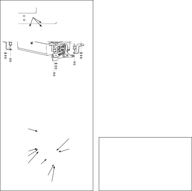
1. Installing to the table
To use the SC-922 with the direct-motor type machine head, install the control box on the table according to the following instruction.
1
!0
9
2
3
 6
6
4 5
7
8
This describes the procedure for installing the
SC-922 on the table of the LU-2810-7 sewing machine. To use any other machine head, install the control box on the table referring to the Instruction
Manual for the main body of the relevant sewing machine. Install the control box suspending plate on the table with mounting bolts supplied with the unit. At this time, insert the nuts and washers supplied with the unit as accessories as shown in the figure so that the motor unit can be securely fixed on the table.
1)Press three bolts 1 supplied with the unit as accessories into the motor hanging bolt hole in the table and fix them.
2)Fix suspending plate 5 supplied with the unit on the three bolts with plain washer 2, spring washer 3 and nut 4.
3)Fix rubber 6 on the suspending plate with spring washer 7 and nut 8.
4)Hang one end of the control box on the threaded part of rubber on the side which has two bolts.
Then, hang the other end of the control box on the opposite side.
5)Temporarily fix the other threaded part of rubber with plain washer 9 and nut !0. In this case, the spring washer is not used.
6)Adjusting the installing position of the control box.
Then, securely tighten the nuts.
––
2. Installing the motor unit
To use the SC-922 with the belt-drive type machine head, install the control box on the motor unit according
to the following instruction.
1
Nat
Spring washer
Convex washer
Install the motor unit on the table with the fitting bolt asm. supplied with the unit as accessories.
At this time, insert the nuts and washers supplied with the unit as accessories as shown in the figure so that the motor unit can be securely fixed on the table.
1)Press three bolts 1 supplied with the unit as accessories into the motor hanging bolt hole in the table and fix them.
2)Temporarily tighten convex washer, spring washer and nut on the side where two bolts are attached.
3)Hang the motor unit to the washer which has been temporarily tightened, and attach convex washer, spring washer and nut to the other bolt on the opposite side.
4)After adjusting the installing position of the motor, securely tighten the respective nuts.
3. Installing the control box
3
1)Attach bracket 1 supplied with the unit using four supplied screws (M5 x 10) as shown in the figure.
2)Loosen four screws 2 supplied with the motor unit as accessories, tighten screws 2 after
hanging control box unit 3 to the screws, and fix control box unit 3.
––
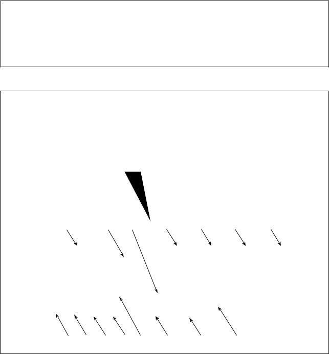
4. Installing the belt
1) The belt distance, between sewing machine pulley and motor pulley, must be parallel.
2) The belt tension should be adjusted by turning the tension adjust nuts 1 to change height of the 15mm (9.8N) motor, so that the belt sinks down by about 15 mm (9.8N) when it is depressed by band at the
center of the belt span.
If the belt tension is not tight, speed is unstable at low-speed or medium-speed operation, and the needle will not stop exactly in position.
1
5. Adjusting the pulley cover
Belt
a
|
1) After adjusting the belt tension, adjust the pulley |
|
b |
cover 1 so that the clearances between the belt |
|
and the pulley cover 1, a and b should be the |
||
|
||
|
same. |
2)After the completion of adjustment, tighten screws
2 located on the side of pulley cover 1 and
1 securely fix the pulley cover 1 so that it does not slip out of position.
1
––
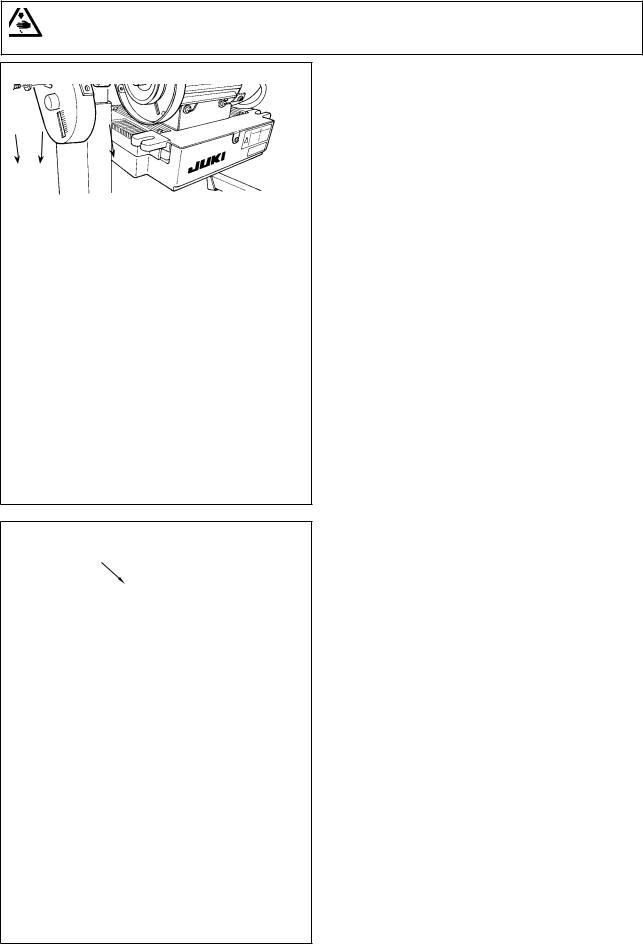
6.Installation and adjustment for the protecting pin and the belt slip-off preventing bracket
WARNING :
To protect against possible personal injury due to abrupt start of the machine, be sure to start the following work after turning the power off and ascertaining that the motor is at rest.
1
2 3
Belt |
|
Attaching |
Attaching |
hole A |
hole B |
Belt |
4 mm or less |
|
|
|
1 |
4 mm or less
Adjusting position for protecting pin
Pulley
cover Motor pulley
Belt
3 mm or less
4
Adjusting position for belt slip-off preventing bracket
1) Attaching hole for the protecting pin
To attach protecting pin 1, select either attaching hole A or attaching hole B in the motor pulley cover in accordance with the direction of rotation of the sewing machine and attach the pin in the selected hole using screw 2 and washer 3 supplied with the unit.
a) If the motor shaft rotates in direction A in the figure on the above:
→Attach protecting pin 1 in attaching hole A .
b)If the motor shaft rotates in direction B in the figure on the above:
→Attach protecting pin 1 in attaching hole B .
2)Adjustment for the protecting pin and the belt slip-off preventing bracket
Adjust the position of protecting pin 1 and belt slip-off preventing bracket 4 in accordance with the figure on the left.
a)Adjusting the protecting pin
Loosen screw 2 and adjust so that protecting pin 1 is positioned at the location indicated in the figure on the left.
b)Adjusting belt slip-off preventing bracket Loosen screw 5 and adjust so that belt slipoff preventing bracket 4 is positioned at the location indicated in the figure on the left.
If protecting pin 1 is not properly adjusted, it is possible that your fingers may be caught in the clearance provided between the pulley and the belt resulting in injury. If belt slip-off preventing bracket 4 is not properly ad-
justed, it is possible to allow the belt to slip off causing safety hazard.
3)After the adjustment, tighten screws 2 and 5 so as to secure protecting pin 1 and belt slip-off preventing bracket 4 to prevent these components to fluctuate because of vibration.
4)Before starting the operation of the sewing machine, ascertain that protecting pin 1 and belt slip-off preventing bracket 4 do not come in contact with the pulley and the belt.
––
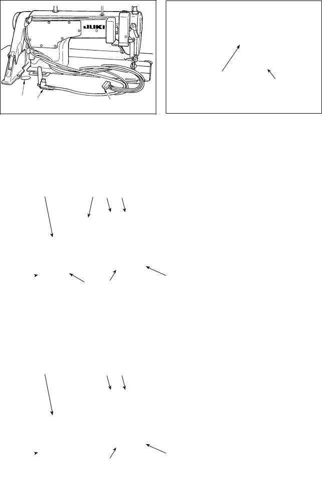
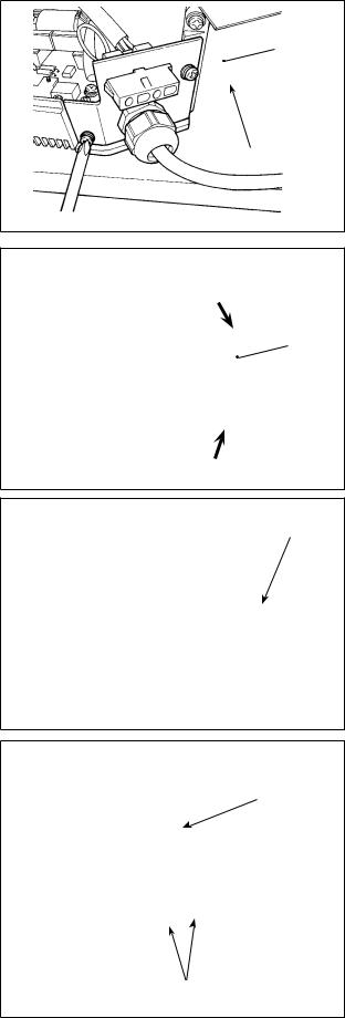
7. Connecting the cords
WARNING :
• To prevent personal injury caused by abrupt start of the sewing machine, carry out the work after turning OFF the power switch and a lapse of 5 minutes or more.
• To prevent damage of device caused by maloperation and wrong specifications, be sure to connect all the corresponding connectors to the specified places.
• To prevent personal injury caused by maloperation, be sure to lock the connector with lock.
• As for the details of handling respective devices, read carefully the Instruction Manuals supplied with the devices before handling the devices.
Following connectors are prepared on the SC-922. Connect the connectors coming from the machine head to the corresponding places so as to fit the devices mounted on the machine head.
!2 |
2 |
!5 |
3 |
4 |
7 |
8 |
1 |
!1 5 |
6 |
9 |
!0 |
!4 |
!3 |
1 CN30 Motor signal connector
2 CN33 Needle bar position detector (+5V type): It detects the needle bar position.
3 CN36 Machine head solenoid: Provided with solenoids for thread trimming, reverse feed stitching, one-touch type reverse feed switch.
4 CN37 Presser foot lifting solenoid (Only for the automatic presser foot lifter type)
5 CN38 Operation panel: Various kinds of sewing can be programmed. (For details of the operation panel other than CP-18, refer to the Instruction
Manual for the panel to be used.)
6 CN39 Standing machine pedal : JUKI standard PK70, etc. Sewing machine can be controlled with external signals.
7 CN40 Single-needle control solenoid: It is used with the LH-4100 sewing machine provided with a single-needle control device.
8 CN41 Stepping motor: It is used only with the DLU-
5494N-7.
9 CN43 Synchronizer (+12V type) : It detects the needle bar position.
!0CN44 Hand switch: Hand switch other than the touch-back switch.
!1CN48 Safety switch (standard) : When tilting the sewing machine without turning the power OFF, the operation of the sewing machine is prohibited so as to protect against danger. OPTION switch: Input function can be changed by changing over the internal function with this switch.
!2CN51 Extended input/output connector
!3CN55 LED lamp (+5 V type): The LED lamp can be connected optionally. (Refer to "III-4. Onetouch setting" p.20 for how to adjust the quantity of light.)
!4CN58 Extended input connector (for the sensor input, etc.)
!5CN59 Extended output connector (for the solenoid valve output)
––
B
3
21
1)Pass cords 1 of the thread trimmer solenoid, reverse feed solenoid and detector cords 2 through table hole A and route them under the table. (Detector cord 2 is not provided for the direct-motor type machine head.)
[For the belt-drive type machine head]
2)Loosen screw B in cover 3 with a screwdriver to open the cover.
For the direct-motor type machine head, proceed to step 4).
!1 |
9 5 7 |
3) Connect 14P code 4 coming |
|
|
|
|
from the machine head to con- |
|
|
|
nector 5 (CN36). |
|
|
|
When the optional AK device |
|
|
|
is attached, connect 2P con- |
|
|
|
nector 6 coming from the AK |
|
|
|
device to connector 7 (CN37). |
|
|
|
Insert connector 8 coming |
|
|
|
from the detector into connec- |
!0 |
|
6 |
tor 9 (CN33). |
|
8 |
4 |
Connect 9P connector !0com- |
|
|
|
|
|
|
|
ing from the motor to connector |
|
|
|
!1(CN30) on the circuit board. |
|
|
|
Proceed to step 5). |
(Caution) When using the AK device, set whether to use the AK device after confirming how to select the auto-lifter function. (Refter to “III-14. Setting of the auto lifter function” p. 51.)
[For the direct-motor type machine head] |
|
||||
|
|
|
4) |
Connect 14P cord 4 coming |
|
!1 |
5 |
7 |
|||
|
from the machine head to con- |
||||
|
|
|
|
||
|
|
|
|
nector 5 (CN36). Connect 2P |
|
|
|
|
|
connector 6 to connector 7 |
|
|
|
|
|
(CN37). |
|
|
|
|
|
Connect 9P connector !0 |
|
|
|
|
|
coming from the motor to con- |
|
|
|
|
|
nector !1(CN30) on the circuit |
|
|
|
|
|
board. |
|
!0 |
4 |
6 |
|
Proceed to step 5). |
|
|
|
|
|
||
|
|
|
|
|
|
––
[Connecting the connector for the operation panel]
!3
!2
5)The connector for the operation panel is provided. Paying attention to the orientation of the connector !2, connect it to connector (CN38) !3located on the circuit board. After connecting, securely
lock the connector.
(Caution) Be sure to turn OFF the power before connecting the connector.
[ Connection of the pedal of standing-work machine ]
|
6) To use the pedal unit with the sewing machine |
|
|
|
for standing work, insert PK70 connector !4into |
|
connector !5(CN39: 12P) on the PCB. |
!5 |
(Caution) Be sure to turn OFF the power before |
|
connecting the connector. |
!4
(Caution) Be sure to securely insert the respective connectors after checking the inserting directions
since all connectors have the inserting directions. (When using a type with lock, insert the connectors until they go to the lock.) The sewing machine is not actuated unless the connectors are inserted properly. In addition, not only the problem of error warning or the like occurs, but also the sewing machine and the control box are damaged.
[How to bundle all cords]
!6
7)After inserting the connector, put all cords together with cable clip band !6located on the side of
the box.
(Caution) 1. Fix the cord clamp and the cable clip band following the attaching procedure.
2.When removing the connector, remove it from the wire saddle and remove it while pressing the hook of the cable clip band.
How to fix cable clip band |
|
How to remove cable clip band |
|
|
|||
Panel |
Panel |
Pushing the |
|
|
|
|
hook portion, |
|
Push the |
|
push the band |
|
hook. |
|
to remove it. |
Pull |
|
Push |
|
|
|
|
|
––
B
3
!8
!7
@0!9
[For CE specifications only]
@1
@2
CE 1ø 230V |
Brown |
|
AC |
|
|
||
|
Blue |
|
220V-240V |
|
|
||
|
|
Green / Yellow (ground wire)
8) Close cover 3 and fix the cover by tightening screw B with a screwdriver.
(Caution) Take care not to allow the cord to be caught under cover 3.
9)Connect connector 4P !7to connector !8located on the side of the box.
10)Connect motor output cord !9of the power switch to connector @0.
Connect motor output cord @1to connector @2located on the side of the box.
Installing power switch
Connect power supply cord to the power switch.
[CE specifications]
Single phase 230V : Power supply cords : Brown, Blue, and green/yellow (ground wire)
––
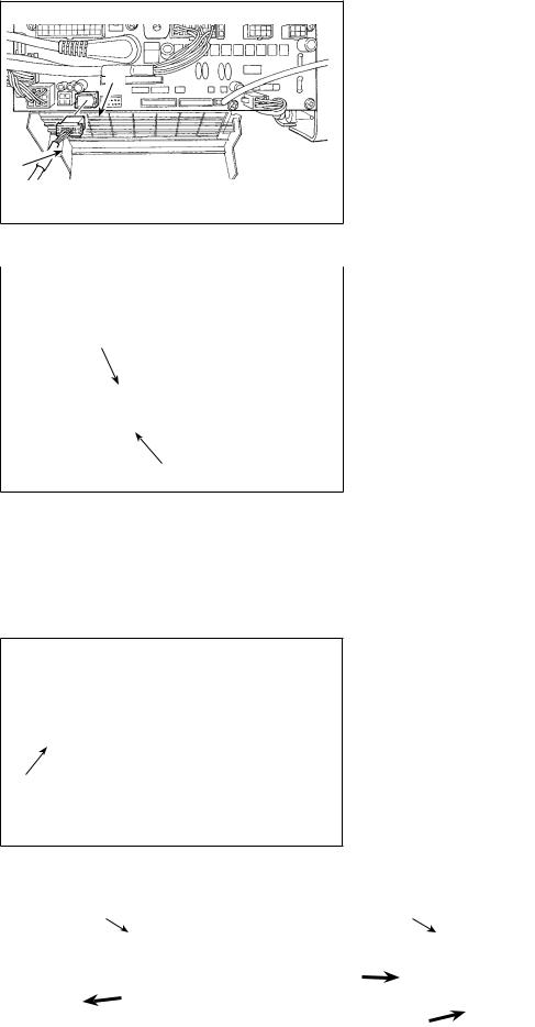
[Changing over the voltage between 100 V and 200 V]
WARNING :
To prevent personal injuries caused by electric shock hazards or abrupt start of the sewing machine, carry out the work after turning OFF the power switch and a lapse of 5 minutes or more. To prevent accidents caused by unaccustomed work or electric shock, request the electric expert or engineer of our dealers when adjusting the electrical components.
1
*The illustration below shows the PWR-T PCB. The type of PCB differs by destination.
A
Wiring for the single-phase 100 V |
|
||
Be sure to connect the wire between 1 and 2. |
|||
If it is connected between 1-3 or 2-3, the sewing |
|||
(Box side)machine will be inoperative. |
(Plug side) |
||
WHITE |
1 WHITE |
||
|
|||
BLACK |
2 BLACK |
|
|
RED |
3 |
|
|
GREEN/ |
GREEN/ |
|
|
YELLOW |
YELLOW |
|
|
B
Wiring for the 3-phase 200 V |
(Plug side) |
|
(Box side) |
||
1 WHITE |
||
WHITE |
||
BLACK |
2 BLACK |
|
RED |
3 RED |
|
GREEN/ |
GREEN/ |
|
YELLOW |
YELLOW |
C
Wiring for the single-phase 200 V
Be sure to connect the wire between 1 and 2.
If it is connected between 1-3 or 2-3, the sewing machine will be inoperative.
(Box side) |
WHITE |
1 WHITE (Plug side) |
|
||
|
BLACK |
2 BLACK |
|
RED |
3 |
|
GREEN/ |
GREEN/ |
|
YELLOW |
YELLOW |
By making the following two changes, the SC-922 can be used with three different power supplies, i.e., singlephase 100 - 120 V, single-phase 200 to 240 V and 3-phase 200 to 240 V.
*Only the control box which uses PWR-T PCB can be changed.
1 Replacement of the power cords
2 Changing-round of connector 1 on the PWR PCB
1)Turn OFF the power with the power switch after checking that the sewing machine has stopped.
2)Draw out the power cord from the power receptacle after checking that the power switch has been turned OFF. Then wait for 5 minutes or more.
3)Loosen the screws which are used to secure the rear lid of the control box cover. Carefully open the rear cover.
4)Changing procedure of the power voltage
(Caution) If the supply power changing is carried out in a wrong manner, the control box can break. Be extremely careful when taking the supply voltage changing procedure.
A.To change over the supply voltage from 200 - 240 V to 100 - 120 V
Change the power cord with the JUKI genuine cord with the part number (M90355800A0). Change the earth cord with the one with the part number (M90345800A0).
Change over supply voltage changeover connector 1 mounted on the PWR PCB with the connector for 100 V.
Connect the crimp style terminal of AC input cord to the power plug as shown in the figure A.
B,C. To change over the supply voltage from 100 - 120 V to 200 - 240 V
Change the power cord with the JUKI genuine cord with the part number M90175800A0).
Change over supply voltage changeover connector 1 mounted on the PWR PCB with the connector for 200 V.
Connect the crimp contact of the AC input cord to the power plug as illustrated in Fig. B for the 3-phase power supply or as illustrated in Fig. C for the single-phase one.
5)Before closing the rear lid of the cover, ascertain again that the relevant parts have been correctly changed without fail.
6)Close the read lid while pressing it, taking care not to allow the wiring to be caught between the read lid of the cover and the main body of the control box. Then, secure the lid with the screws.
|
(Caution) Be sure to remove the |
|
connector while hold- |
|
ing its locking section |
|
with your fingers. Be |
|
extremely careful not |
|
to pull the connector |
Locking section |
forcibly. |
––

[In case of using the power switch for LA]
Connect motor output cord @1to connector @2located on the side of the box.
@1
@2
JA 3ø 220V |
Black |
|
|
|
|
AC |
|
|
Red |
|
|
|
|
||
|
|
200V-240V |
|
|
|
||
|
White |
|
|
|
|
|
Green / Yellow (ground wire) Black AC
White  100V-120V
Green / Yellow (ground wire)
Installing power switch
Connect power supply cord to the power switch.
[JA specifications]
3-phase 220 V : Power supply cords : black, white, red and green/yellow (ground wire)
Single phase 120V : Power supply cords : black, white, and green/yellow (ground wire)
When the metallic conduit is used, be sure to change over the power cord section following the steps of procedure described below.
(Caution) Be sure to carry out this procedure before installing the control box on the machine table.
A
B
1Place the control box with its frame side down on the machine table as illustrated in the sketch.
2Loosen screw B in underside cover A to open the cover.
3Change over the cord shown in the red-line circle following the steps of procedure described below.
– 10 –
4Remove two screws C to remove clamping plate
D from the main body of the control box.
D
 C
C
5 Remove connector E while holding its locking
section F with your fingers.
F
E
F
6 Turn connector G to remove the cord locking
Gsection.
7Loosen nut H to remove the connector from clamping plate D.
D
H
– 11 –
D |
I |
J |
I |
D |
J |
J
I
K
A
B
8Put locknut I on the power cord and draw out the cord J from inside clamping plate D.
9 Install clamping plate D back to the control box. !0Pass power cord J through conduit K.
!1Fix conduit K with locknuts I with clamping plate D placed between the locknuts.
!2Close underside cover A and secure the cover with screw B.
– 12 –

@3
@3
11) Make sure that the power switch is turned OFF and insert power supply cord coming from the power switch into the power plug socket.
(Caution) 1. Top end of power supply cord varies in accordance with destination or supply voltage. Check again the supply voltage and the voltage designated on the control box when installing the switch.
2.Be sure to prepare power plug @3 conformed to the safety standard.
3.Be sure to connect the ground wire ( green / yellow).
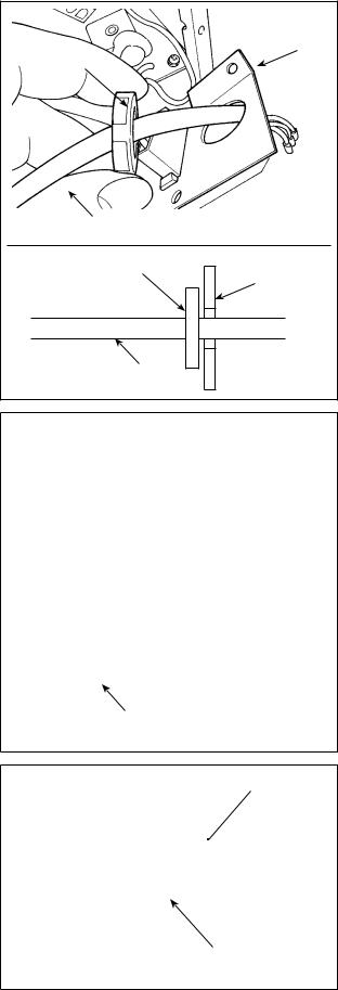
8. Attaching the connecting rod
WARNING :
To protect against possible personal injury due to abrupt start of the machine, be sure to start the following work after turning the power off and a lapse of 5 minutes or more.
1) Fix connecting rod 1 to installing hole B of pedal lever 2 with nut 3.
2) Installing connecting rod 1 to installing hole A will lengthen the pedal depressing stroke, and the pedal operation at a medium speed will be easier.
2
1
3BA
– 13 –
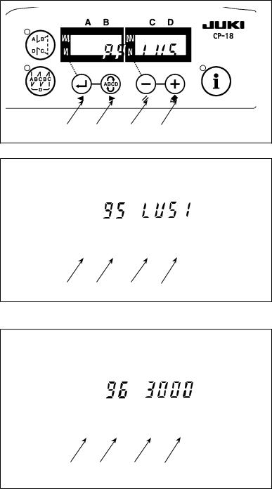
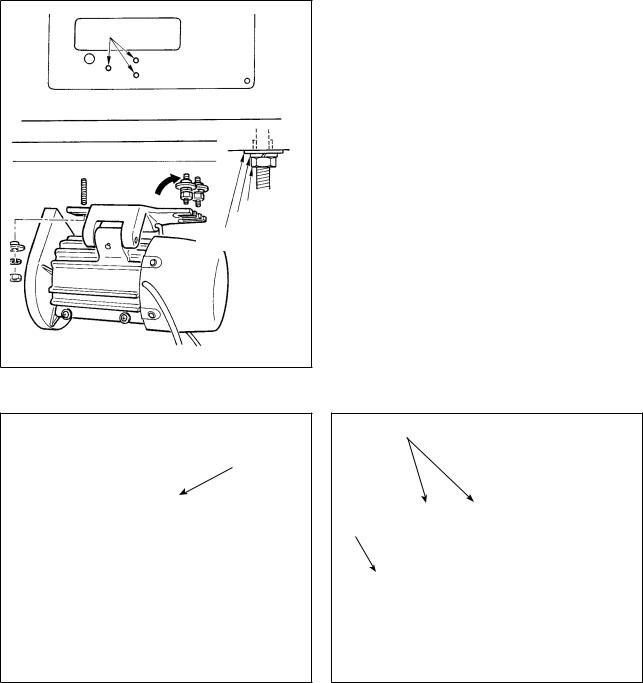
9. Setting procedure of the machine head
(Caution) For the operation panel other than CP-18, refer to the Instruction Manual for the operation panel to be used for the setting procedure of the machine head.
1) Refer to "III-6. Setting of functions of SC-922" p.25, and call the func- tion setting No. 95.
3 4 5 6
2) The type of machine head can be selected by pressing  switch 5 (
 switch 6).
* Refer to the "List of machine heads" on the separate sheet or the Instruction Manual for the machine head of
your sewing machine for the type of
the machine head.
3 4 5 6
3) After selecting the type of machine head, by pressing  switch 3 (
 switch 4), the step proceeds to
94 or 96, and the display automatically changes to the contents of the setting corresponding with the type of machine head.
3 4 5 6
– 14 –

10. Adjusting the machine head (direct-drive motor type sewing machine only)
(Caution) 1. When the slip between the marker dot on the handwheel and the concave of the cover is excessive after thread trimming, adjust the angle of the machine head by the operation below.
2.The machine head parts of which are connector to CN33 or CN43 does not need adjustment. (Refer to “II-7. Connecting the cords” p. 5.)
A |
1) Simultaneously pressing |
switch |
|
|
4 and |
switch 5, turn ON the |
|
power switch.
2) 


 is displayed (A) in the indicator and the mode is changed over to the adjustment mode.
3 4 5 6
|
3) Turn the pulley of the machine head |
B |
|
|
by hand until the main-shaft reference |
|
signal is detected. At this time, the de- |
|
gree of an angle from the main-shaft |
|
reference signal is displayed on the |
|
indicator B. |
|
(The value is the reference value.) |
3 4 5 6
4) In this state, align marker dot 7 on the pulley with recess 8 on the pulley cover.
8
 7
7
5) Press |
switch 6 to finish the |
adjustment work. (The value is the reference value.)
3 4 5 6
– 15 –
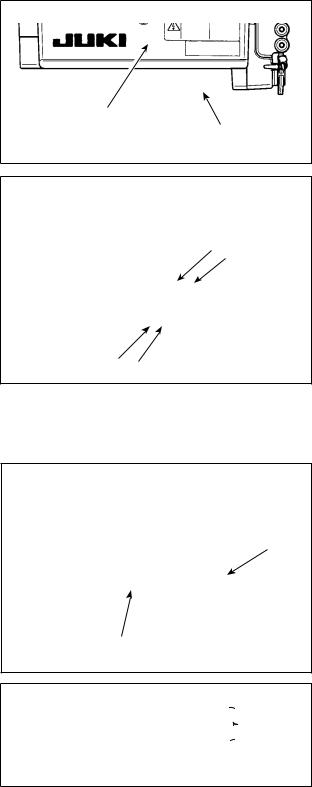
III.FOR THE OPERATOR
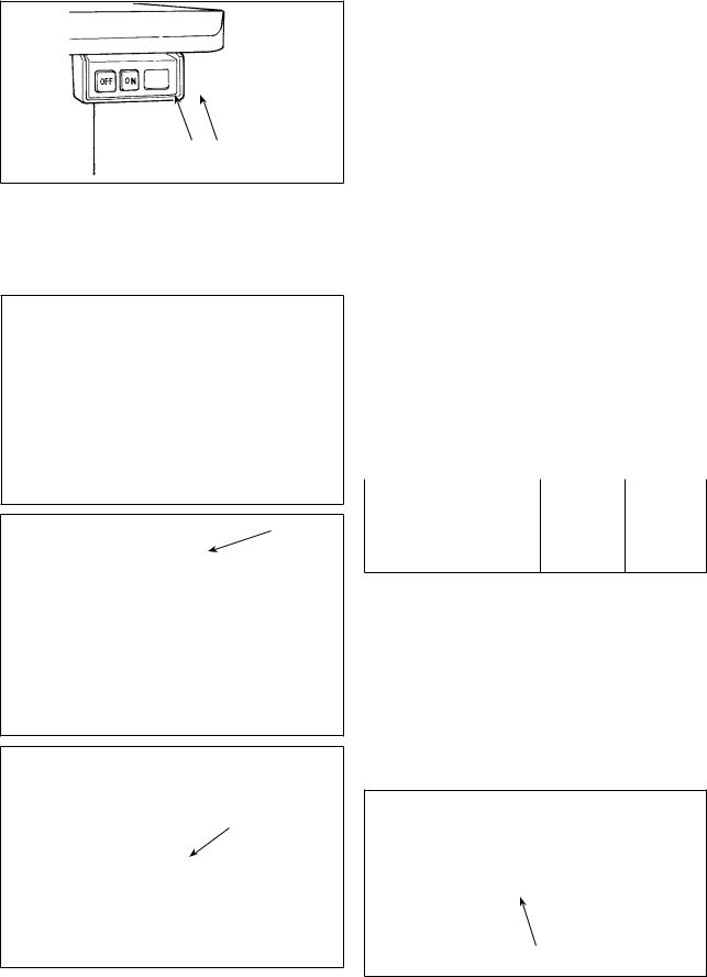
1.Operating procedure of the sewing machine
1)Press ON button 1 of the power switch to turn ON the power.
|
(Caution) If the power indication LED does not |
|
|
light up even when turning ON the power |
|
|
switch, immediately turn OFF the power |
|
|
switch and check the voltage. |
|
|
In addition, in such a case as this, re-turn |
|
2 |
ON the power switch when 2 to 3 min- |
|
utes or more have passed after turning |
||
|
||
|
OFF the power switch. |
5
4
3
|
PFL |
KFL |
|
Presser foot operation |
Enabled |
Disabled |
|
by pedal |
|||
|
|
||
Pedal depressing depth |
Deep |
Shallow |
|
for thread trimming |
|||
|
|
6) For some types of the sewing machine heads, it is possible to program various sewing patterns, using the operation panel, such as the reverse feed stitching at sewing start and that at sewing
end. When you use CP-18 6 with your sewing machine, refer to "III-3. Operating procedure of the sewing pattern" p.18 for details. When you
use any other operation panel with your sewing machine, refer to the Instruction Manual for the respective operation panel. (The figure given illustrates the case of the LU-1510N-7.)
7)For some types of the sewing machine heads, reverse feed is performed by pressing touch-back switch 7. (The figure given illustrates the case of the LU-1510N-7.)
2
8)When sewing is completed, press OFF button 2 of the power switch to turn OFF the power switch after confirming that the sewing machine has stopped.
– 16 –
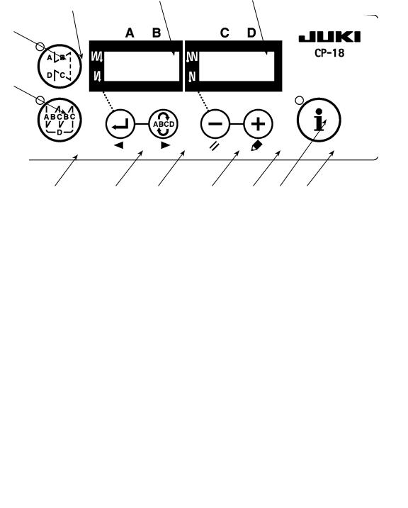
2. Operation panel (CP-18)
AB
1
C
D
|
2 |
3 |
4 |
5 |
6 |
E |
7 |
1 |
switch : Used for changing over effective/ineffective of the reverse feed stitching pattern. |
||||||
2  switch : Used for changing over effective/ineffective of the overlapped stitching pattern.
3switch : Used for confirming the contents of setting and for changing over effective/ineffective of
the reverse feed stitching at sewing start.
4switch : Used for selecting the process (A, B, C, D) the number of stitches for which is to be
changed.
* The selected process flashes on and off.
5switch : Used for changing the content of the selected display (flashing section) and for changing
over effective/ineffective of the reverse stitch at sewing end.
6  switch : Used for changing the content of the selected display (flashing section).
7switch : Used to call the production support function or one-touch setting (by keeping the switch
held pressed for one second).
Indicators A and B : Various pieces of information are displayed. LED C : Lights up when the reverse feed stitching pattern is effective. LED D : Lights up when the overlapped stitching pattern is effective.
LED E : Lights up when the production support function is displayed. Flashes on and off when invoking the one-touch setting.
– 17 –
Loading...