


 Loading...
SC-920
INSTRUCTION MANUAL
|
CONTENTS |
|
I. SPECIFICATIONS........................................................................................ |
1 |
|
II. SET-UP........................................................................................................ |
1 |
|
1. |
Changing over the voltage between 100 V and 200 V.......................................................................... |
2 |
2. |
Installing to the table.............................................................................................................................. |
3 |
3. |
Installing the control panel..................................................................................................................... |
5 |
4. |
Connecting the cords............................................................................................................................. |
6 |
5. Attaching the connecting rod.............................................................................................................. |
12 |
|
6. |
Setting procedure of the machine head.............................................................................................. |
13 |
7. Adjusting the machine head (direct-drive motor type sewing machine only)................................. |
14 |
|
III. FOR THE OPERATOR............................................................................. |
15 |
|
1. |
Operating procedure of the sewing machine..................................................................................... |
15 |
2. |
Operation panel (CP-18)....................................................................................................................... |
17 |
3. |
Operating procedure of the sewing pattern........................................................................................ |
18 |
|
(1) Reverse feed stitching pattern.............................................................................................................. |
18 |
|
(2) Overlapped stitching pattern................................................................................................................. |
19 |
4. |
One-touch setting.................................................................................................................................. |
20 |
5. |
Production support function................................................................................................................ |
21 |
6. |
Setting of functions of SC-920............................................................................................................. |
24 |
7. |
Function setting list.............................................................................................................................. |
25 |
8. |
Detailed explanation of selection of functions................................................................................... |
29 |
9. Automatic compensation of neutral point of the pedal sensor........................................................ |
39 |
|
10. |
Selection of the pedal specifications.................................................................................................. |
39 |
11. Setting of the auto lifter function......................................................................................................... |
40 |
|
12. |
Selecting procedure of the key-lock function.................................................................................... |
41 |
13. |
Connection of the pedal of standing-work machine.......................................................................... |
41 |
14. |
External input / output connector........................................................................................................ |
42 |
15. |
Connection of the material end sensor............................................................................................... |
43 |
16. |
Initialization of the setting data............................................................................................................ |
44 |
IV. MAINTENANCE....................................................................................... |
44 |
|
1. |
Removing the rear cover...................................................................................................................... |
44 |
2. |
Replacing the fuse................................................................................................................................ |
45 |
|
(1) PWR PCB................................................................................................................................................. |
45 |
|
(2) CTL PCB.................................................................................................................................................. |
46 |
3. |
Error codes............................................................................................................................................ |
46 |
i
I. SPECIFICATIONS
Supply voltage |
Single phase 100 to 120V |
3-phase 200 to 240V |
Single phase 220 to 240V |
|
|
|
|
Frequency |
50Hz/60Hz |
50Hz/60Hz |
50Hz/60Hz |
Operating envi- |
Temperature : 0 to 40˚C |
Temperature : 0 to 40˚C |
Temperature : 0 to 40˚C |
ronment |
Humidity : 90% or less |
Humidity : 90% or less |
Humidity : 90% or less |
Input |
320VA |
320VA |
320VA |
*The power consumption values shown in the above table are reference values in the case the main body of the sewing machine used with the SC-920 is DDL-9000B.
The power consumption differs with the machine head to be selected.
II.SET-UP
SC-920 is a discrete control box and can be used with the DD (direct-drive) system sewing machine head.
To use a compact motor unit, the motor unit has to be installed on the table in prior to the installation of the control box on it. To connect the SC-920 to a compact motor, assemble them referring to "M92 SUPPLEMENTARY SETUP INSTRUCTIONS".
In the case the SC-920 is used for the DD (direct-drive) type sewing machine head, install the control box on the table following the instructions give below.
SC-920 control box
SC-920 control box (For installing the compact motor)
– 1 –
1. Changing over the voltage between 100 V and 200 V
WARNING :
To prevent personal injuries caused by electric shock hazards or abrupt start of the sewing machine, carry out the work after turning OFF the power switch and a lapse of 5 minutes or more. To prevent accidents caused by unaccustomed work or electric shock, request the electric expert or engineer of our dealers when adjusting the electrical components.
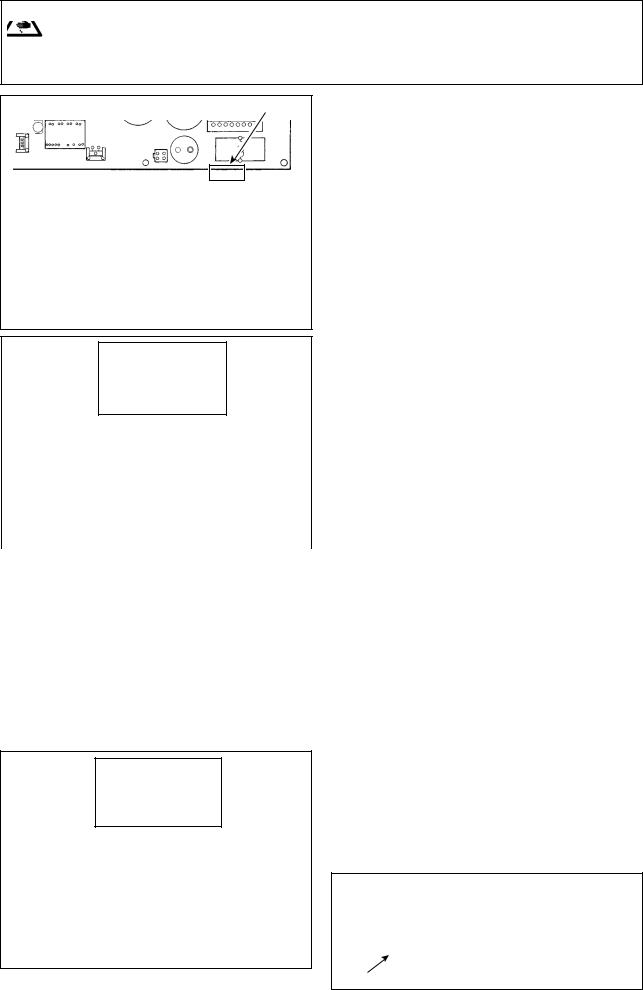
*The illustration below shows the PWR-T PCB. The type of PCB differs by destination.
A
Wiring for the single-phase 100 V
Be sure to connect the wire between 1 and 2.
If it is connected between 1-3 or 2-3, the sewing
(Box side)machine will be inoperative. |
(Plug side) |
||||
WHITE |
1 WHITE |
||||
|
|
||||
BLACK |
2 BLACK |
|
|
||
RED |
3 |
|
|
||
GREEN/ |
GREEN/ |
|
|
||
YELLOW |
YELLOW |
|
|
||
|
|
|
|
|
|
|
|
|
|
|
|
B |
|
|
|
|
|
|
|
|
|
||
|
|
|
|
|
|
Wiring for the 3-phase 200 V |
(Plug side) |
||||
(Box side) |
|||||
1 WHITE |
|
|
|||
WHITE |
|
|
|||
BLACK |
2 BLACK |
|
|
||
RED |
3 RED |
|
|
||
GREEN/ |
GREEN/ |
|
|
||
YELLOW |
YELLOW |
|
|
||
|
|
|
|
|
|
C
Wiring for the single-phase 200 V
Be sure to connect the wire between 1 and 2.
If it is connected between 1-3 or 2-3, the sewing machine will be inoperative.
(Box side) |
1 WHITE |
(Plug side) |
|
WHITE |
|||
|
|||
BLACK |
2 BLACK |
|
|
RED |
3 |
|
|
GREEN/ |
GREEN/ |
|
|
YELLOW |
YELLOW |
|
Depending on specifications of the control box, the number of phases and the voltage of the power supply can be changed over among "single-phase 100 - 120 V," "single-phase 200 - 240 V" and "3-phase 200 - 240 V."Replacement of the power cords
Changing-round of connector on the PWR PCB
1)Turn OFF the power with the power switch after checking that the sewing machine has stopped.
2)Draw out the power cord from the power receptacle after checking that the power switch has been turned OFF. Then wait for 5 minutes or more.
3)Loosen the screws which fix the cover of the control box. Open the cover in a slow manner.
4)Changing procedure of the power voltage
(Caution) If the supply power changing is carried out in a wrong manner, the control box can break. Be extremely careful when taking the supply voltage changing procedure.
A. To change over the supply voltage from 200 - 240 V to 100 - 120 V
•Change the power cord with the JUKI genuine cord with the part number (M90355800A0). Change the earth cord with the one with the part number (M90345800A0).
•Change over supply voltage changeover connector mounted on the PWR PCB with the connector for 100 V.
•Connect the crimp style terminal of AC input cord to the power plug as shown in the figure A.
B,C. To change over the supply voltage from 100 - 120 V to 200 - 240 V
•Change the power cord with the JUKI genuine cord with the part number (M90175800A0).
•Change over supply voltage changeover connector mounted on the PWR PCB with the connector for 200 V.
•Connect the crimp contact of the AC input cord to the power plug as illustrated in Fig. B for the 3-phase power supply or as illustrated in Fig. C for the single-phase one.
5)Before closing the door, check to be sure again that the voltage has been changed without mistake.
6)Close the back lid and secure with the screws pressing the lid, while taking extra care to prevent the cord from being caught between the cover and the main body of the control box.
(Caution)
|
Be sure to remove the connec- |
|
tor while holding its locking |
|
section with your fingers. Be |
|
extremely careful not to pull |
Locking section |
the connector forcibly. |
|
– 2 –
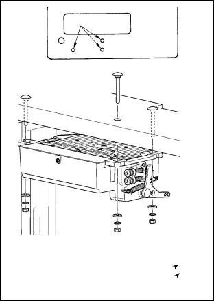
2. Installing to the table
In the case the SC-920 is used for the DD (direct-drive) type sewing machine head, install the control box on the table following the instructions give below.
The description given below refers to the case the
SC-920 is installed on the table of the DDL-9000B. Touse any other machine head, install the control box
on the table referring to the Instruction Manual for the main body of the relevant sewing machine.
1) Install the control box to the table with the fitting bolt (asm.) supplied with the unit as accessories. At this time, insert the nut and washer supplied with the unit as accessories as shown in the figure so that the control box is securely fixed.
2) After having installed the control box (and the compact motor) on the table, mount the sewing machine head on the table. (Refer to the Instruction Manual for the sewing machine to be used.)
Plain washer
Spring washer
Hexagonal nut
– 3 –

[How to install the reactor box]
WARNING :
Be sure to install the reactor box after turning the power OFF.
* For the EU-type models, install the reactor box that is supplied with the sewing machine.
|
|
|
|
1) Connect the terminals of power cord of the |
|
|
SC-920 to reactor-box PCB asm. and to |
||
|
|
|
|
|
|
|
|
|
reactor box mounting plate . |
|
|
|
A |
Connect brown wire A to the first connector |
|
|
|
C |
and blue wire B to the third connector respec- |
|
|
|
B |
tively from the top of terminal block on the |
|
|
|
|
reactor box PCB asm. using screws. Connect |
|
|
|
|
green/yellow wire C to reactor box mounting |
|
|
|
|
plate with earth setscrew . |
|
|
|
|
2) Attach cable clip to the power cord of SC- |
|
|
|
920. Attach the power cord together with the |
|
|
|
|
||
|
|
|
|
cable clip to reactor box mounting plate |
|
|
|
with cable clip setscrew . |
|
|
|
|
|
3) Attach cord bushes to input/output cables |
|
|
|
|
|
|
|
|
and of the reactor box. |
|
|
|
|
|
|
|
|
|
|
4) Attach reactor box cover to reactor box |
|
|
|
mounting plate with four reactor-box cover |
|
|
|
|
|
setscrews . |
|
|
|
|
At this time, fix cord bushes attached to |
|
|
|
input/output cables and in the concave |
|
|
|
section on reactor box cover to eliminate a |
||
|
|
|
|
gap between reactor box and cover . |
|
|
|
|
5 Install reactor box on the table stand with |
|
|
|
|
four accessory wood screws at the posi- |
|
|
|
|
tion that is approximately 200 mm away from |
|
|
|
|
the front end of table stand. |
|
|
|
|
Adjust the installing position according to |
|
|
|
|
the size of table stand so that the reactor |
|
|
|
box does not protrude from the edge of table |
|
|
|
|
||
|
|
|
|
stand. |
Undersurface of table |
|
|
|
6) Fix input/output cables and of reactor |
|
|
|
|
box on the table stand using accessory |
|
|
|
cord staple . |
|
|
|
|
|
At this time, take care not to cross the input- |
|
SC-920 |
|
|
and output-cables. |
|
|
|
|
|
|
|
|
mm |
|
Power box |
|
|
||
|
200 |
|
||
|
|
|
|
|
Operator’s side |
|
|
|
|
|
|
|
– 4 – |
|
3. Installing the control panel
WARNING :
To protect against possible personal injury due to abrupt start of the machine, be sure to start the following work after turning the power off and a lapse of 5 minutes or more.
1) Remove side plate setscrews from the side plate.

|
|
2) Install control panel on the machine head using |
|
|
|
|
screws , flat washers and rubber seat sup- |
|
|
plied with the control panel as the accessories. |
|
|
|
|
|
|
(Caution) 1. DDL-9000B (Not provided with AK) is |
|
|
given as an example of installing proce- |
|
|
dure. |
|
|
2. Screw to install the panel changes |
|
according to the machine head used. |
|
|
|
|
|
|
Refer to Table 1 and confirm the kind of |
|
|
screw. |
|
|
|
< The relation between the respective machine heads and the positions of installing hole of the bracket are as described in the table. >
|
|
|
|
|
|
Table 1 |
|
|
|
|
|
|
|
|
|
|
|
|
|
|
|
|
|
|
|
|
|
|
|
|
|
|
|
|
|
|
|
|
|
Installing |
|
Screw |
|
|
|
|
|
|
|
|
hole |
|
||
|
|
|
|
|
|
|
|
|
|
|
|
|
|
|
|
|
|
|
(Provided with AK) |
|
|
|
|
|
|
|
|
DDL-9000B |
- |
M5 X 14 |
|
Side plate setscrew |
|
|
|
|
|
|
(Not provided with AK) |
||||
|
|
|
|
|
|
|
|
|
||
|
|
|
|
|
|
|
|
M5 X 12 |
|
|
|
|
|
|
|
|
LH-3500A |
- |
M5 X 14 |
|
Side plate setscrew |
|
|
|
|
|
|
DLN-9010 |
- |
3/16-28 L=12 |
|
Screw supplied with |
|
|
|
|
|
|
|
panel as accessories |
|||
|
|
|
|
|
|
|
|
|
|
|
|
|
|
|
|
|
DDL-8700 series |
- |
3/16-28 L=12 |
|
Screw supplied with |
|
|
|
|
|
|
|
panel as accessories |
|||
|
|
|
|
|
|
|
|
|
|
|
|
|
|
|
|
|
DDL-5500 series *1 |
- |
3/16-28 L=12 |
|
Screw supplied with |
|
|
panel as accessories |
||||||||
|
|
|
|
|
|
|
|
|
|
|
|
|
|
|
|
|
|
|
|
|
|
|
|
|
|
|
|
LZ-2280 series *1 |
- |
11/64-40 L=7.8 |
|
Screws supplied with |
|
|
|
|
|
|
|
|
|
|
machine head |
|
|
|
|
|
|
*1 For the DDL-5556 |
and LZ-228*, the machine head is supplied with an auxiliary |
|||
|
|
|
|
|
|
bracket for mounting the control panel as an accessory. Be sure to install the |
||||
|
|
|
|
|
|
bracket while referring to the instruction manual for the machine head. |
||||
(Caution) |
1. |
Screws to be used for installing the panel differ with the machine head, i.e., screws supplied with |
||||||||
|
|
the panel as accessories and the side plate setscrews. Select appropriate screws/setscrews refer- |
||||||||
|
|
ring to Table 1. |
|
|
|
|
|
|
|
|
2.If the screw type is not correct, the tapped hole can be collapsed.
3.If you want to install the panel on the DDL-8700, be aware that the method to install it on the machine head differs depending on whether or not the machine head is provided with the AK device.
Machine head with the AK device:
Install the panel on the head bracket supplied with the AK. (The auxiliary bracket should be fixed with the side plate setscrews.)
Machine head without the AK device:
Remove the side plate setscrews and install the panel on the side plate using the screws supplied with panel as accessories.
4.If you want to use the panel with the machine head for heavy-weight materials, install it referring to the "Supplementary Instructions" for the machine head.
–5 –
4. Connecting the cords
WARNING :
•To prevent personal injury caused by abrupt start of the sewing machine, carry out the work after turning OFF the power switch and a lapse of 5 minutes or more.
•To prevent damage of device caused by maloperation and wrong specifications, be sure to connect all the corresponding connectors to the specified places. (If any of the connectors is inserted into a wrong connector, not only the device corresponding to the connector can break but also it can start abruptly, inviting the risk of personal injury.)
•To prevent personal injury caused by maloperation, be sure to lock the connector with lock.
•As for the details of handling respective devices, read carefully the Instruction Manuals supplied with the devices before handling the devices.
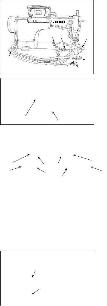
The SC-920 is provided with the connectors listed below. Connect the sewing-machine connectors to the corresponding control-box connectors according to the devices installed on the sewing machine.
(Caution) For the SC-920 Series, the machine head to be used with is to be selected in the course of the function setting procedure. To prevent an insertion error, remove the resistor pack for the machine head selection before use.
|
|

|
|
|
CN30 Motor signal connector
CN38 Operation panel: Various kinds of sewing can be programmed. (For details of the operation panel other than CP-18, refer to the Instruction Manual for the panel to be used.)
CN33 Synchronizer : It detects the needle bar position.
CN37 Presser foot lifting solenoid (Only for the automatic presser foot lifter type)
CN48 Safety switch (standard) : When tilting the sewing machine without turning the power OFF, the operation of the sewing machine is prohibited so as to protect against danger.
CN42 Thread trimming safety switch
CN39 Standing machine pedal : JUKI standard PK70, etc. Sewing machine can be controlled with external signals.
CN58 +24 V external power source
CN57 Simplified production control counter input
CN36 Machine head solenoid: Provided with solenoids for thread trimming, reverse feed stitching, one-touch type reverse feed switch.
CN54 Material end detection sensor, etc.
CN50 Optional function/device input/output.
CN34 Pedal sensor: The pedal sensor supplied with the SC-920 is to be connected to this connector to operate the sewing machine.
– 6 –
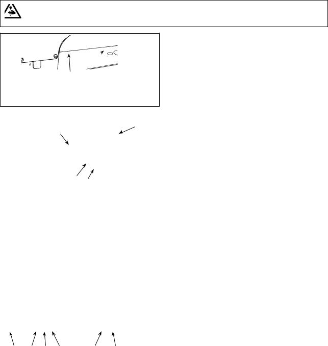
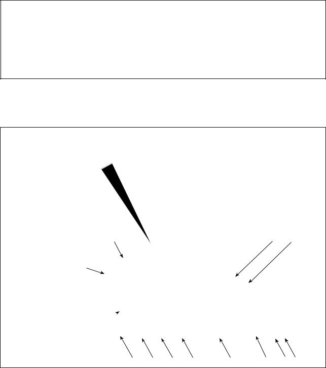
1) Pass cords of the thread trimming solenoid, reverse-stitching solenoid, etc. and the cord from the motor through hole A in the table to route them down under the machine table.
|
|
A


2) Loosen screw B in cover with a screwdriver to open the cover.
B |
|
|
|
|
|
3) |
Connect 14P code coming from |
|
|
|
||
|
|
|
|
the machine head to connector |
|
|
|
|
(CN36). |
|
|
|
4) |
When the optional AK device is |
|
|
|
|
attached, connect 2P connector |
|
|
|
|
coming from the AK device to con- |
|
|
|
nector (CN37). |
|
|
|
|||
|
|
|
5) |
Connect connector coming from |
|
|
|
the motor to connector (CN30) on |
|
|
|
|
||
|
|
|
|
the circuit board. |
|
|
|
6) |
Insert 4P cord coming from the ma- |
|
|
|
||
|
|
|
|
chine head into connector (CN48). |
(Caution) 1. When using the AK device, set whether to use the AK device after confirming how to select the auto-lifter function. (Refer to “III-11. Setting of the auto lifter function” p.40.)
2.Be sure to securely insert the respective connectors after checking the inserting directions since all connectors have the inserting directions. (When using a type with lock, insert the connectors until they go to the lock.) The sewing machine is not actuated unless the connectors are inserted properly. In addition, not only the problem of error warning or the like occurs, but also the sewing machine and the control box are damaged.
[Connecting the connector for the operation panel]
The SC-920 is provided with a connector for the operation panel. Fully insert connector into connector (CN38) on the PWB until it locks without fail while carefully checking the orientation of connector .
(Caution) Be sure to turn OFF the power before connecting the connector.
– 7 –
[ Connection of the pedal of standing-work machine ]
Connect the connector of PK70 to connector (CN39 : 12P) of SC-920.
(Caution) Be sure to turn OFF the power before connecting the connector.

|
7) |
After inserting the connector, put all cords together |
||
|
|
|||
|
|
|
with cable clip band located on the side of the |
|
|
|
|
box. |
|
|
|
(Caution) |
1. Fix the cord clamp and the cable clip |
|
|
|
|
|
band following the attaching proce- |
|
|
|
|
dure. |
|
|
|
|
2. When removing the connector, |
|
|
|
|
remove it from the wire saddle and |
|
|
|
|
remove it while pressing the hook of |
|
|
|
|
the cable clip band. |
|
|
|
|
|
|
|
How to remove cable clip band |
||
How to fix cable clip band |
|
|
||
Panel |
|
|
Panel |
Pushing |
|
|
|
|
the hook |
|
Push the |
portion, push |
||
|
the band to |
|||
|
|
hook. |
||
|
|
remove it. |
||
|
|
|
|
|
Pull |
|
|
Push |
|
|
|
|
|
|
B


9)Connect connector 4P to connector located on the side of the box.
10)Connect motor output cord of the power switch to connector .
8) Close cover and fix the cover by tightening screw B with a screwdriver.
(Caution) Take care not to allow the cord to be caught under cover .
11)Bundle the machine head cables with a cable clip
supplied with the operation panel at one location as shown in the figure.
– 8 –
3ø 200V-240V |
Black |
|
Red  AC 200V-240V
White 
Green / Yellow (ground wire)
Black AC 100V-120V White
  AC 220V-240V
Green / Yellow (ground wire)
12)Connect the power supply cord to the power plug socket. Connect, as shown in the figure, the white and black (and red) conductors or the brown and blue conductors to the power supply side and the
green/yellow conductor to the grounding side.
(Caution) 1. Be sure to prepare the power plug which conforms to the safety standard.
2.Be sure to connect the earth cable (green/yellow) properly.
[For CE specifications only]
Connect motor output cord to connector located on the side of the box.

CE 1ø 230V
Brown |
|
AC |
|
||
Blue |
|
220V-240V |
|
Green / Yellow (ground wire)
Installing power switch
Connect power supply cord to the power switch.
[CE specifications]
Single phase 230V : Power supply cords : Brown, Blue, and green/yellow (ground wire)
(Caution) 1. Be sure to prepare the power plug which conforms to the safety standard.
2.Be sure to connect the earth cable (green/yellow) properly.
– 9 –
[In case of using the power switch for LA]
Connect motor output cord to connector located on the side of the box.
3ø 220V |
Black |
|
|
|
|
AC |
|
|
Red |
|
|
|
|
||
|
|
200V-240V |
|
|
White |
|
|
|
|
|
|
|
|
|
Green / Yellow (ground wire) Black  AC
AC
White  100V-120V
Green / Yellow (ground wire)
Installing power switch
Connect power supply cord to the power switch.
[LA specifications]
3-phase 220 V : Power supply cords : black, white, red and green/yellow (ground wire)
Single phase 120V : Power supply cords : black, white, and green/yellow (ground wire)
(Caution) 1. Be sure to prepare the power plug which conforms to the safety standard.
2.Be sure to connect the earth cable (green/yellow) properly.
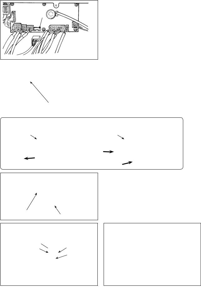
When the metallic conduit is used, be sure to change over the power cord section following the steps of procedure described below.
(Caution) Be sure to carry out this procedure before installing the control box on the machine table.
A
 B
B
Place the control box with its frame side down on the machine table as illustrated in the sketch.
Loosen screw B in underside cover A to open the cover.
D
 C
C
Remove two screws C to remove clamping plate D from the main body of the control box.
Change over the cord shown in the circle following the steps of procedure described below.
F
E
F
Remove connector E while holding its locking section F with your fingers.
– 10 –
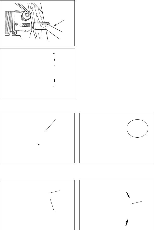
G
Turn connector G to remove the cord locking sec-
tion. |
|
I |
D |
|
|
J |
|
I |
D |
|
|
J |
|
Put locknut I on the power cord and draw out the cord J from inside clamping plate D .
A
B
D
H
Loosen nut H to remove the connector from clamping plate D .
J
I
K
Install clamping plate D back to the control box.
Pass power cord J through conduit K .
Fix conduit K with locknuts I with clamping plate
D placed between the locknuts.
Close underside cover A and secure the cover with screw B .
13)Make sure that the power switch is turned OFF and insert power supply cord coming from the power
switch into the power plug socket.
(Caution) Top end of power supply cord varies in accordance with destination or supply voltage. Check again the supply voltage and the voltage designated on the control box when installing the switch.
– 11 –
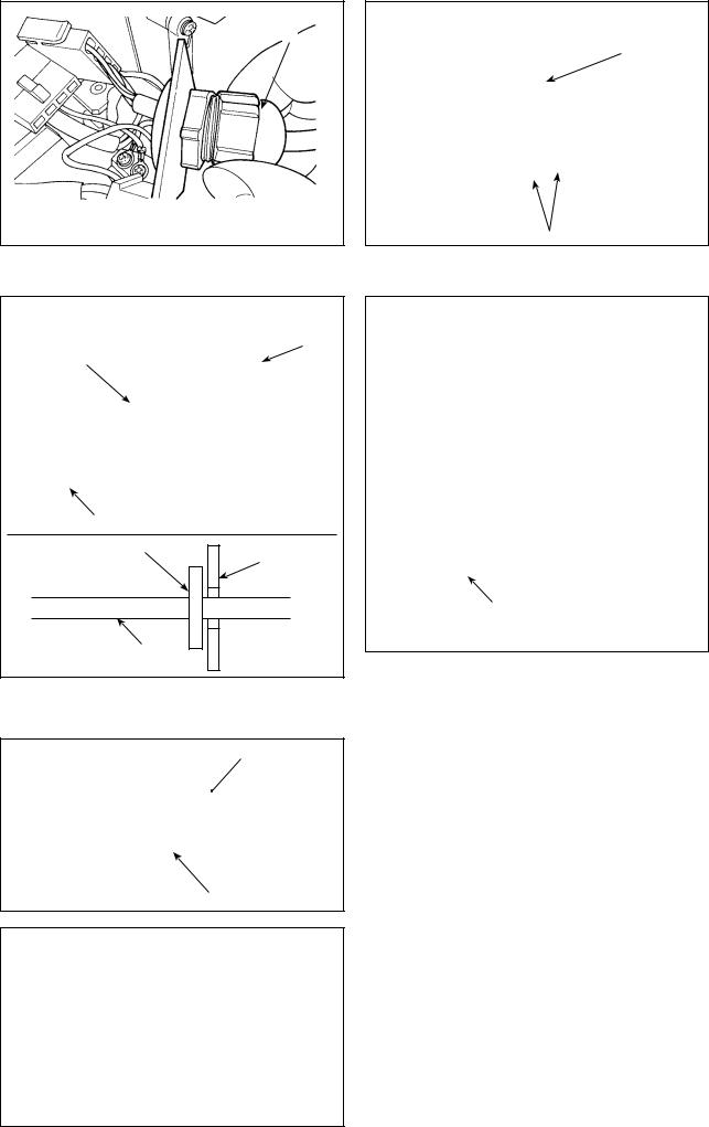
5. Attaching the connecting rod
WARNING :
To protect against possible personal injury due to abrupt start of the machine, be sure to start the following work after turning the power off and a lapse of 5 minutes or more.


1) Fix connecting rod to installing hole B of pedal lever with nut .
2)Installing connecting rod to installing hole A will lengthen the pedal depressing stroke, and the pedal operation at a medium speed will be easier.
3)The pressure increases as you turn reverse depressing regulator screw in, and decreases as
you turn the screw out.
(Caution) 1. If the screw is excessively loosened, the spring will come off.
Loosen the screw to such an extent that the top of the screw can be observed from the case.
2.Whenever you have adjusted the
screw, be sure to secure the screw by tightening metal nut to prevent the screw from loosening.
– 12 –
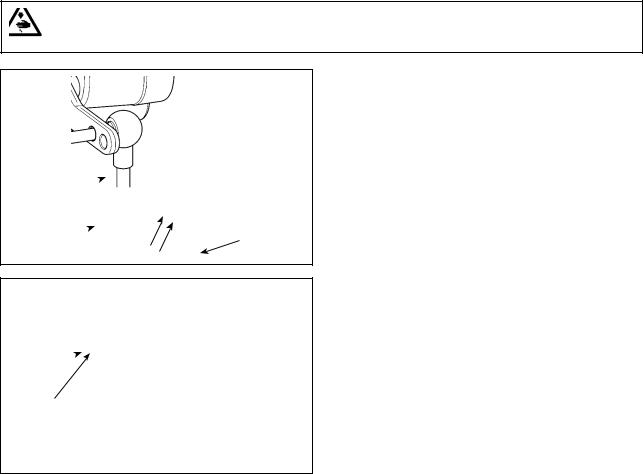
6. Setting procedure of the machine head
(Caution) For the operation panel other than CP-18, refer to the Instruction Manual for the operation panel to be used for the setting procedure of the machine head.
1) Refer to “III-6. Setting of functions of SC-920” p.24, and call the function setting No. 95.
2) The type of machine head can be selected by pressing  switch (
 switch ).
* Refer to the "MACHINE HEAD LIST" on the separate sheet or the Instruction Manual for the machine head of your sewing machine for the type of the machine head.
3) After selecting the type of machine head, by pressing  switch (
 switch ), the step proceeds to
96 or 94, and the display automatically changes to the contents of the setting corresponding with the type of machine head.
– 13 –
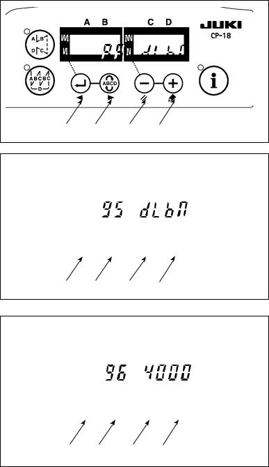
7. Adjusting the machine head (direct-drive motor type sewing machine only)
(Caution) When the slip between the white marker dot on the handwheel and the concave of the cover is excessive after thread trimming, adjust the angle of the machine head by the operation below.
|
1) Simultaneously pressing |
switch |
|
|
and |
switch , turn ON the |
|
|
power switch. |
|
|
|
2) |
is displayed ( ) in the indica- |
|
|
tor and the mode is changed over to |
||
|
the adjustment mode. |
|
|
|
3) Turn the pulley of the machine head |
|
by hand until the main-shaft reference |
||
|
||
|
signal is detected. At this time, the de- |
|
|
gree of an angle from the main-shaft |
|
|
reference signal is displayed on the in- |
|
|
dicator . (The value is the reference |
|
|
value.) |
4) In this state, align the white dot of the handwheel with the concave of the pulley cover as shown in the figure.
5) Press switch to finish the
adjustment work. (The value is the reference value.)

– 14 –
Loading...