

Page 1

DDL-9000C-F
INSTRUCTION MANUAL
Page 2

CONTENTS
1. SPECIFICATIONS ............................................................................................................ 1
1-1. Specications of the sewing machine head ..................................................................... 1
1-2. Specications of the control box
2. SET UP .............................................................................................................................2
2-1. Drawing of table ................................................................................................................... 2
2-2. Cautions when setting up the sewing machine
2-2-1. How to carry the sewing machine ............................................................................................ 3
2-2-2. Caution when placing the sewing machine .............................................................................3
2-3. Installation ............................................................................................................................ 3
2-4. Installing the thread stand
2-5. Installing the electrical box
2-6. Connecting the power switch cable
2-6-1. Installing the power switch ....................................................................................................... 5
2-6-2. Connecting the power source cord ..........................................................................................6
2-6-3. Installing the reactor box ..........................................................................................................7
2-7. Connecting the cords .......................................................................................................... 8
2-8. Handling the cords
.............................................................................................................. 9
2-9. Attaching the connecting rod
2-10. Adjustment of the pedal
2-10-1. Installing the connecting rod ................................................................................................ 10
2-10-2. Adjusting the pedal angle .....................................................................................................10
2-11. Pedal operation .................................................................................................................. 10
2-12. Lubrication
......................................................................................................................... 11
2-13. How to use the operation panel (Basic explanation)
2-13-1. Selection of the language (operation to be done at rst) ..................................................12
2-13-2. Names and functions of the panel keys ..............................................................................14
2-13-3. Basic operation ...................................................................................................................... 15
.................................................................................................. 4
.................................................................................................... 10
....................................................................................... 1
................................................................ 3
................................................................................................ 5
.................................................................................. 5
............................................................................................. 9
..................................................... 12
3. PREPARATION BEFORE SEWING .............................................................................. 16
3-1. Attaching the needle ......................................................................................................... 16
3-2. Removing/tting the bobbin case
3-3. Winding the bobbin thread
............................................................................................... 17
3-4. Threading the machine head
3-5. Thread tension
3-5-1. Adjusting the thread tension No. 1 tension ........................................................................... 20
3-5-2. Adjusting the needle thread tension (Active tension) .......................................................... 20
3-5-3. Adjusting the bobbin thread tension .....................................................................................20
................................................................................................................... 20
3-6. Presser foot (Active presser device) ............................................................................... 21
3-6-1. Presser foot pressure .............................................................................................................. 21
3-6-2. Micro-lifter function .................................................................................................................21
3-6-3. Changing the initial value of presser foot pressure ............................................................. 22
3-6-4. Manual lifter .............................................................................................................................. 22
3-7. Adjusting the stitch length ............................................................................................... 23
3-8. Changing the sewing speed
3-9. LED hand light
3-10. Reverse feed stitching
3-11. Custom switch
................................................................................................................... 24
...................................................................................................... 24
................................................................................................................... 25
.................................................................................... 16
............................................................................................ 19
............................................................................................. 23
i
Page 3

3-12. Adjusting the amount of oil (oil splashes) in the hook .................................................. 26
3-12-1. Adjusting the amount of oil in the hook ..............................................................................26
3-12-2. How to conrm the amount of oil (oil splashes) ................................................................. 27
3-12-3. Sample showing the appropriate amount of oil .................................................................. 27
3-13. Adjusting the thread take-up spring and the thread take-up stroke............................. 28
4. HOW TO USE THE OPERATION PANEL .....................................................................29
4-1. Explanation of the sewing screen (when selecting a sewing pattern) ......................... 29
4-2. Sewing patterns
4-2-1. Sewing pattern conguration .................................................................................................33
4-2-2. List of sewing patterns ............................................................................................................ 34
4-2-3. Reverse feed stitching (at start) pattern ................................................................................ 36
4-2-4. Double reverse-feed stitch ...................................................................................................... 41
4-2-5. Editing the sewing patterns .................................................................................................... 42
4-2-6. List of pattern functions .......................................................................................................... 44
4-2-7. Reverse feed stitching (at end) pattern .................................................................................47
4-2-8. Teaching function .................................................................................................................... 48
4-2-9. One-touch utility changeover function .................................................................................. 50
4-2-10. Registration of a new sewing pattern ..................................................................................51
4-2-11. Copying a pattern ...................................................................................................................53
4-2-12. Narrow-down function ........................................................................................................... 54
4-3. Counter function ................................................................................................................ 56
4-3-1. Displaying the sewing screen under the counter display mode ......................................... 56
4-3-2. Types of the counter ................................................................................................................ 56
4-3-3. How to set the counter ............................................................................................................57
4-3-4. How to reset the count-completion state ..............................................................................60
4-4. Simplied chart of panel displays ................................................................................... 61
4-5. List of memory switch data
4-6. List of errors
4-7. Memory switch data
................................................................................................................. 33
.............................................................................................. 62
...................................................................................................................... 67
.......................................................................................................... 71
5. MAIN NEW FUNCTIONS ............................................................................................... 73
5-1. Shorter-thread remaining thread trimming ..................................................................... 73
5-2. Adjusting the feed dog height
5-3. Operating timing of the feed
5-4. Changing the feed locus
.......................................................................................... 76
............................................................................................. 77
................................................................................................... 78
6. CARE ............................................................................................................................. 79
6-1. Maintenance mode ............................................................................................................ 79
6-2. Conrmation of the amount of oil in the hook oil tank
6-3. Cleaning
6-4. Applying grease
............................................................................................................................. 80
................................................................................................................. 80
6-5. Applying grease to the needle bar lower bushing and the presser bar bushing
6-6. Replacing the fuse
............................................................................................................. 82
.................................................. 79
........ 81
7. ADJUSTMENT OF THE MACHINE HEAD (APPLICATION) ........................................83
7-1. Needle-to-hook relationship ............................................................................................. 83
7-2. Adjusting the needle thread presser device
7-3. Adjusting the thread trimmer
7-3-1. For checking of the thread trimming cam timing .................................................................87
7-3-2. Adjustment of the thread trimming cam timing ....................................................................87
7-3-3. Checking of the knife unit ....................................................................................................... 88
........................................................................................... 87
................................................................... 84
ii
Page 4

7-3-4.
Adjustment of the knife unit ..................................................................................... 89
7-3-5. Adjustment of thread trimming speed ...................................................................................90
7-4. Adjustment of the picker ................................................................................................... 91
7-4-1. Checking the standard adjustment ........................................................................................ 91
7-4-2. Standard adjustment ...............................................................................................................91
7-4-3. Standard adjustment (Adjustment at the tip position) ......................................................... 91
7-5. Active-presser multi-layered section detection function............................................... 92
7-5-1. Multi-layered section detection function ............................................................................... 92
7-5-2. Multi-layered-section detection number of stitches setting function ................................. 94
7-6. Grease shortage alarm ...................................................................................................... 95
7-6-1. Regarding the grease shortage alarm ...................................................................................95
7-6-2. E221 Grease-shortage error ....................................................................................................95
7-6-3. Regarding K118 error resetting procedure ............................................................................96
8. HOW TO USE THE OPERATION PANEL (APPLICATION) ..........................................97
8-1. Management of sewing patterns ...................................................................................... 97
8-1-1. Creation of a new pattern ........................................................................................................ 97
8-1-2. Copying a pattern ....................................................................................................................99
8-1-3. Deleting a pattern ...................................................................................................................100
8-2. Setting up the polygonal-shape stitching ..................................................................... 101
8-2-1. Editing a polygonal-shape stitching pattern ....................................................................... 101
8-2-2. Creating a new polygonal-shape stitching pattern
8-2-3. Setting the step from which polygonal-shape stitching is started ................................... 103
8-3. Cycle pattern .................................................................................................................... 104
8-3-1. Selecting the cycle pattern ...................................................................................................104
8-3-2. Editing cycle sewing data ....................................................................................................105
8-3-3. Creating a new cycle pattern ................................................................................................106
8-3-4. Setting the step from which cycle sewing pattern is started ............................................108
8-4. Custom pitch .................................................................................................................... 109
8-4-1. Selecting a custom pitch .......................................................................................................109
8-4-2. Creating a new custom pitch ................................................................................................ 111
8-4-3. Custom pitch edit function ................................................................................................... 114
8-4-4. Copying/deleting a custom pitch ......................................................................................... 115
8-5. Condensation custom pattern ........................................................................................ 116
8-5-1. Selecting the condensation custom .................................................................................... 116
8-5-2. Creating a new condensation custom ................................................................................. 116
8-5-3. Condensation custom edit function ..................................................................................... 119
8-5-4. Copying/deleting a condensation custom ...........................................................................120
8-6. Simple lock of the screen ............................................................................................... 121
8-7. Version information
8-8. Adjustment of brightness of the LED panel
8-9. Information
8-9-1. Data communication ..............................................................................................................123
8-9-2. USB .........................................................................................................................................126
8-9-3. Production management ....................................................................................................... 128
8-9-4. NFC ..........................................................................................................................................131
....................................................................................................................... 123
......................................................................................................... 121
.................................................................. 122
8-10. Key customization ......................................................................................................... 132
8-10-1. Assignable data....................................................................................................................132
8-10-2. How to assign a function to a key ...................................................................................... 133
.............................................................103
iii
Page 5
1. SPECIFICATIONS
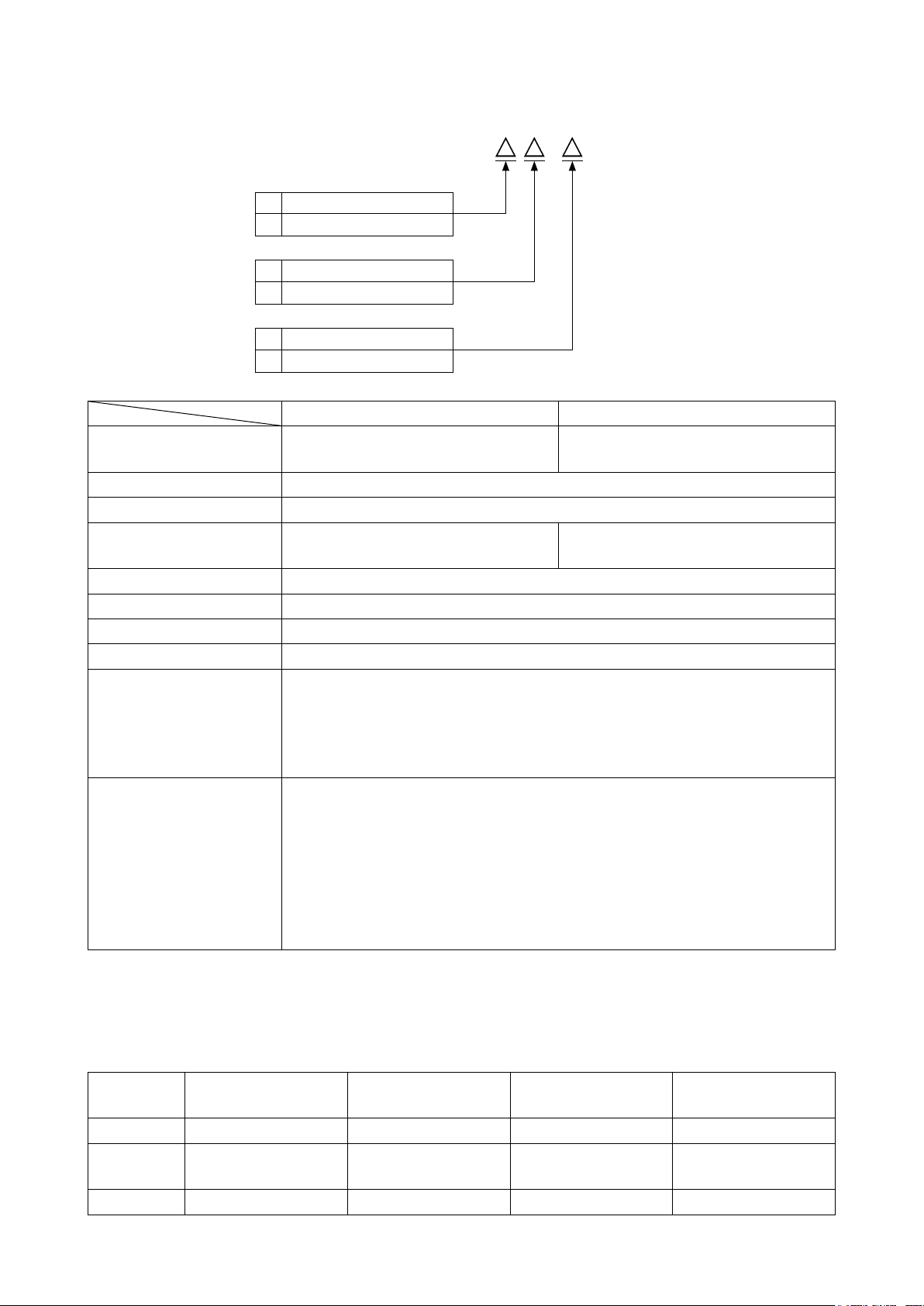
1-1. Specications of the sewing machine head
DDL-9000C-F - B
Face plate portion lubricating method
M Semi-dry
S Micro-quantity lubrication
Seam specication
S Medium-weight materials
H Heavy-weight materials
Needle thread nipper specication
N With
0 Without
DDL-9000C-FMS DDL-9000C-FSH
Max. sewing speed
(standard locus)
Stitch length 5 mm
Presser foot pressure control Electronic control
Needle
Lubricating oil JUKI NEW DEFRIX OIL No. 1 or JUKI CORPORATION GENUINE OIL 7
Motor AC servo motor
Horizontal feed control Electronic control
Vertical feed control Electronic control
Number of patterns
Noise
*1
Stitch length 0 to 4.00 : 5,000 sti/min
Stitch length 4.05 to 5.00 : 4,000 sti/min
1738 Nm65 to 110 (DB×1 #9 to 18)
134 Nm65 to 110 (DP×5 #9 to 18)
Sewing pattern
Cycle sewing pattern ................... 9 patterns
Custom-pitch pattern ................... 20 patterns
Condensation custom pattern .....9 patterns
FMS ;
- Equivalent continuous emission sound pressure level (LpA) at the workstation:
A-weighted value of 81.5 dBA ; (Includes KpA = 2.5 dBA) ; according to ISO 10821-
C.6.2 -ISO 11204 GR2 at 5,000 sti/min.
FSH ;
- Equivalent continuous emission sound pressure level (LpA) at the workstation:
A-weighted value of 77.5 dBA ; (Includes KpA = 2.5 dBA) ; according to ISO 10821-
C.6.2 -ISO 11204 GR2 at 4,500 sti/min.
............................99 patterns (For the polygonal shape sewing, as
many as 10 patterns can be registered.)
Stitch length 0 to 4.00 : 4,500 sti/min
Stitch length 4.05 to 5.00 : 4,000 sti/min
1738 Nm125 to 160 (DB×1 #20 to 23)
134 Nm125 to 160 (DP×5 #20 to 23)
• The sewing speed will vary depending on the sewing conditions. The sewing speed preset at the time of
shipping is 4,000 sti/min.
*1 : Needle used depends on the destination.
1-2. Specications of the control box
Supply
voltage
Frequency 50Hz/60Hz 50Hz/60Hz 50Hz/60Hz 50Hz/60Hz
Operating
environment
Input 520VA 520VA 520VA 350VA
Single phase
100 to 120V
Temperature : 0 to 35˚C
Humidity : 90% or less
3-phase
200 to 240V
Temperature : 0 to 35˚C
Humidity : 90% or less
– 1 –
Single phase
220 to 240V
Temperature : 0 to 35˚C
Humidity : 90% or less
Single phase
220 to 240V CE
Temperature : 0 to 35˚C
Humidity : 90% or less
Page 6
2. SET UP
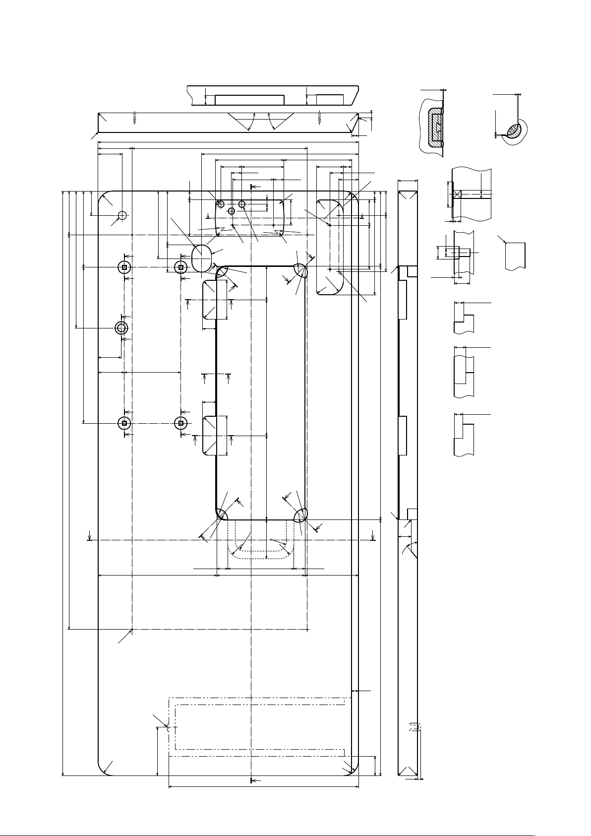
2-1. Drawing of table
90
810
281
U-U
156.5
320
+0.5
322
Y
R8
52
R242.5
R8
21.5
R18
R22.5
0
21
F
Y
R8
139
55
R8
R27.5
R27.5
R2
R2
R2
X-X
10
14
Rubber cushion
17
27.5
40
R30
R6
18
52.5
S
90
195
installing drawing for
R2
R2
50
154.6
115
C1
H
+0.5
0
S-S
20
R2
R2
70
50
18
R30
50
75
110.5
R242.5
C
(138.5)
56
2×R20
VV
535
360
43
R8
S
R8
G
40°
WW
E
141
21.5
40°
86.5
84
9
14
D
Z
V V
R20
R10
X
R10
29
R22.5
Z
68.5±0.5
80
X
Q Q
48
54
116
T
T
29
VV
V
R10
279±1
1±0.5
Y-Y
reference
X-X部ゴム取付参考図
40
∅26
V-V(1:1)
(4ヵ所)
8
1
∅16
∅26
Q-Q
9.5±1
Z-Z
(2ヵ所)
Y-Y
(2ヵ所)
Y-Y部ゴム取付参考図
Rubber cushion
installing drawing for
∅8.5
32±1
1.2±0.5
reference
I
T-T
19.5±0.5
23.5±0.5
17.5±0.5
1.2±0.5
V
80
R10
X
X
X-X
(2ヵ所)
(2 locations) (2 locations) (2 locations) (4 locations)
W-W
1200
(172.5)
Y
R22.5
Z
U
R20
Z
R30
(244)
(22.5)
R20
80
136
-1
181
0
A
R20
R22.5
Y
R18
R30
22.5
110
U
(525.4) 520
(15)
C1
R2
27
40°
B
R30
100
390
R30
R6
(40)
R2
R2
(6)
Installing position of drawer stopper (on the reverse side)
ø17 drilled hole D 3×ø13 drilled hole
2×ø3.5, depth 10
2×ø3.5, depth 10
Through hole
B
C
E
A 4×ø3.4 on the bottom surface, depth 20 (Drill a hole at the time of set-up.)
F
C1.5 to C2.5 (hinge side only)
G
I
H 2×ø3.4 on the bottom surface, depth 10 (Drill a hole at the time of set-up.)
– 2 –
Page 7
2-2. Cautions when setting up the sewing machine
Thank you very much for the purchase of JUKI Industrial Sewing Machine this time. Make sure of items 2-1
through 2-12 before operating to use this sewing machine with ease.
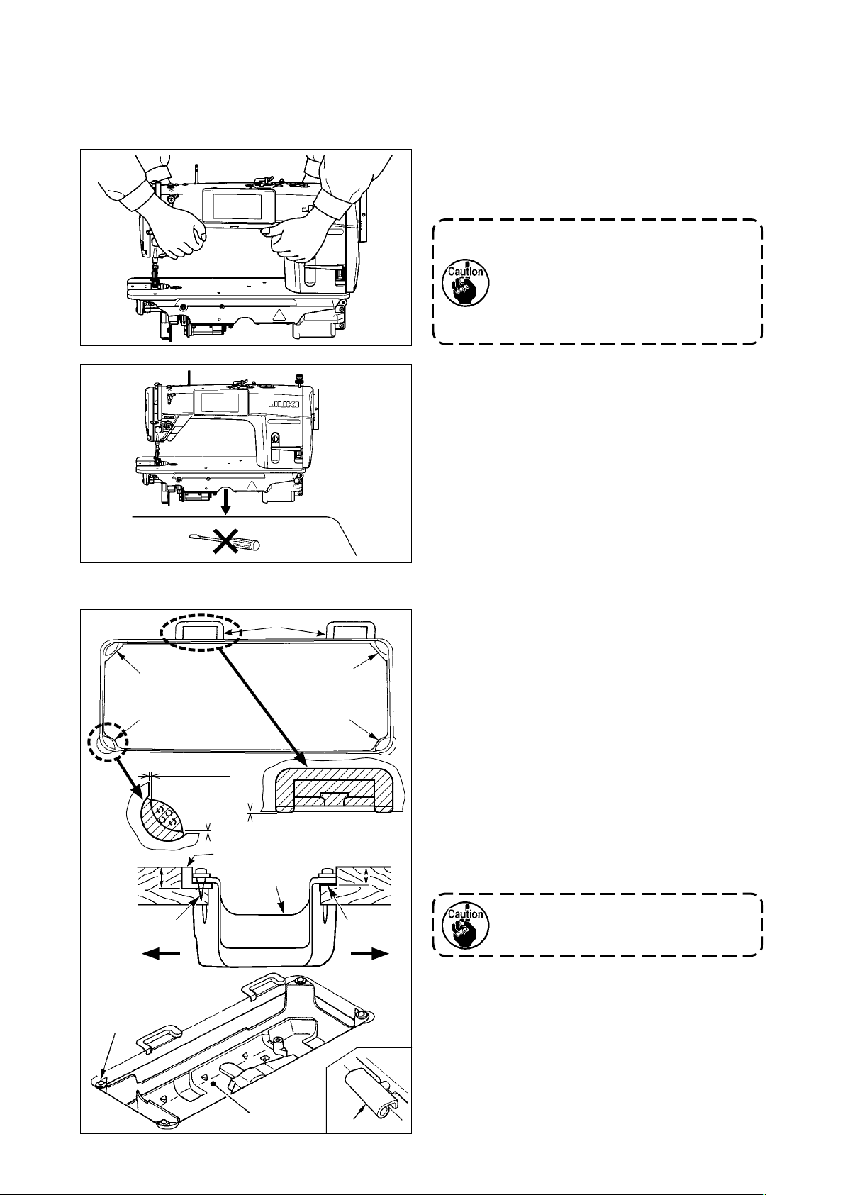
2-2-1. How to carry the sewing machine
Carry the sewing machine while holding the machine
arm with two persons as shown in the gure.
1. Never hold the handwheel since it
rotates.
2. Be sure to handle the sewing
machine with two persons or more
since the sewing machine weighs
40.5 kg or more.
2-2-2. Caution when placing the sewing ma-
chine
Place the sewing machine on a horizontal and plane
place when placing it and do not place any protrud-
ing thing such as a screwdriver or the like.
2-3. Installation
❸
❶
1.2 ± 0.5 mm
23.5 mm
❷
1 ± 0.5 mm
1.2 ± 0.5 mm
❶
A
❹
❺
❸
❶
19.5 mm
❸
B
1) The under cover ❹ should rest on the four cor-
ners of the machine table groove. Mount rubber
hinge seat ❺ on the table and x it on the table
with a nail.
2) Fix two rubber seats ❶ on side A (operator’s
side) using nails ❷ as illustrated above. Fix two
cushion seats ❸ on side B (hinged side) using a
rubber-based adhesive. Then place under cover
❹ on the xed seats.
3) Fit hinge ❼ into the opening in the machine bed,
and t the machine head to table rubber hinge
seat ❺ before placing the machine head on cushions ❽ on the four corners.
Do not hold the handwheel.
❽
❹
❼
– 3 –
Page 8
❻
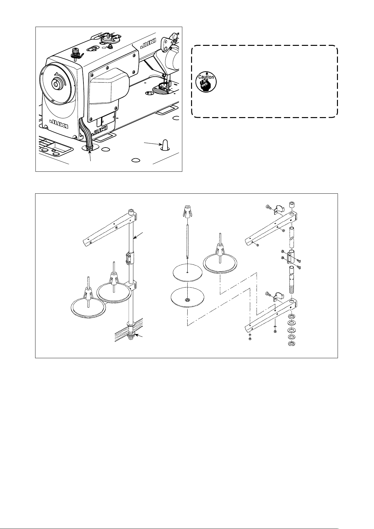
2-4. Installing the thread stand
4) Securely attach head support rod ❾ to the table
until it goes no further.
Be sure to mount the machine head
support rod ❾ on the machine table so
that its height from the table surface
becomes 63 to 68 mm. For the sewing
machine provided with the AK device,
be sure to mount the support rod ❾ on
the table so that its height from the table
surface becomes 33 to 38 mm.
5) Bundle cable clip band ❻ supplied as accessories
of the machine head at the root of the cable.
❾
❷
❶
1) Assemble the thread stand unit, and insert it in the hole in the machine table.
2) Tighten nut ❶.
3) For ceiling wiring, pass the power cord through spool rest rod ❷.
– 4 –
Page 9
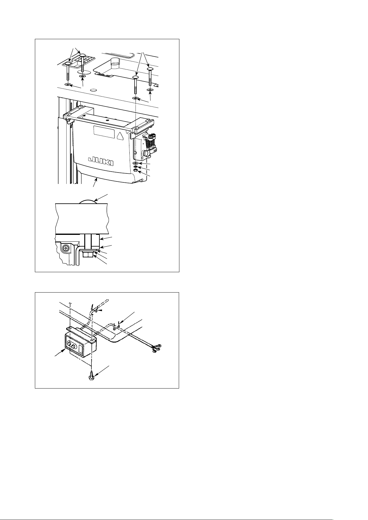
2-5. Installing the electrical box
❷
a
❶
❷
❷
a
Install control box ❶ on the table using four holes
a in the table. Secure the control box with four bolts
❷, four plain washers ❸, four spring washers ❹
and four hexagonal nuts ❺ supplied with the control
box.
At this time, insert the nut and washer supplied with
the unit as accessories as shown in the gure so
that the control box is securely xed.
❸
❹
❺
Frame
Pedal sensor
❸
❹
❺
2-6. Connecting the power switch cable
❸
❶
❷
2-6-1. Installing the power switch
Fix power switch ❶ under the machine table with
wood screws ❷.
Fix the cable with staples ❸ supplied with the ma-
chine as accessories in accordance with the forms
of use.
– 5 –
Page 10
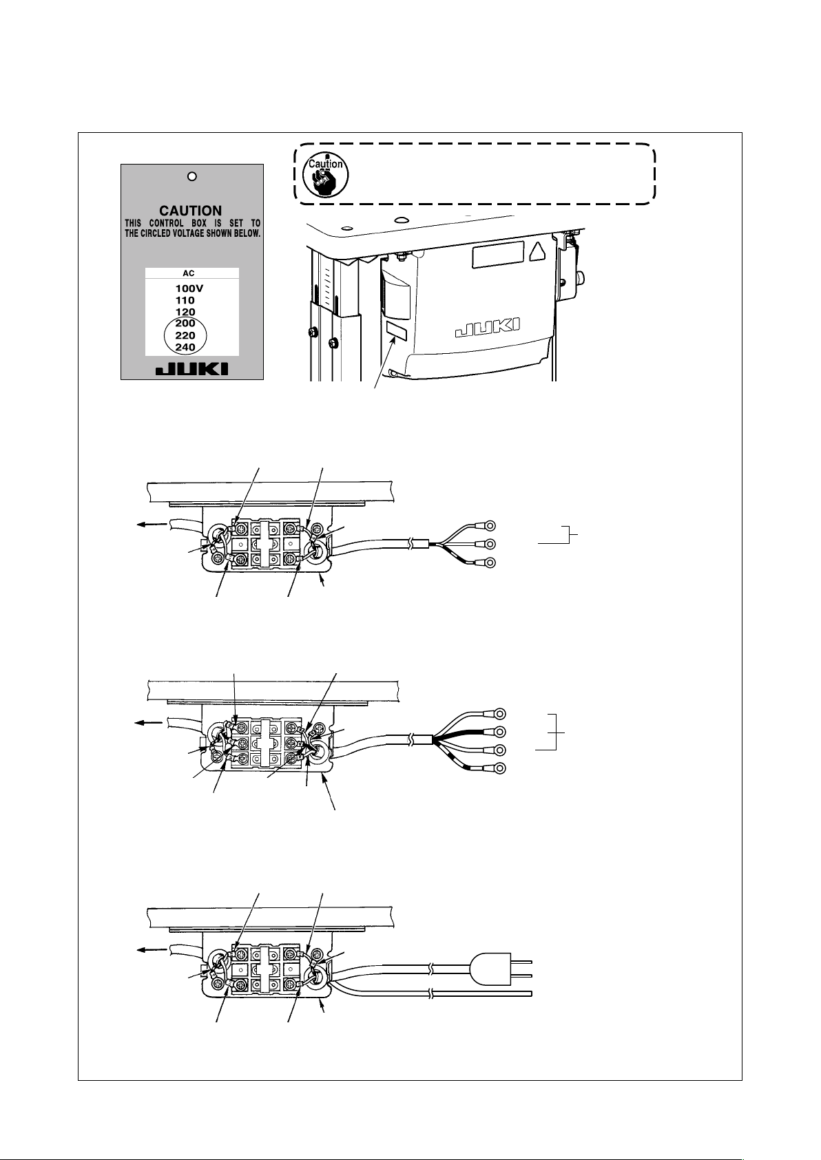
2-6-2. Connecting the power source cord
Voltage specications at the time of delivery from the factory are indicated on the voltage indication seal.
Connect the cord in accordance with the specications.
Power indication tag
Never use under the wrong voltage and phase.
(For example : In the case of 200V)
• Connecting single phase 220 to 240V
Control box
Green/Yellow
Table
Light blue
Brown
Light blue
Brown
Power switch
• Connecting 3-phase 200 to 240V
White
Table
Control box
Green/Yellow
Black
Red
Black
Red
Power switch
Rating plate
Green/Yellow
White
Green/Yellow
Light blue
Brown
Green/Yellow — GND
White
Black
Red
Green/Yellow — GND
AC220 to 240V
AC200 to 240V
• Connecting single phase 100 to 120V
Control box
Green/Yellow
Table
Light blue
Brown
Light blue
Brown
Power switch
Green/Yellow
– 6 –
Page 11
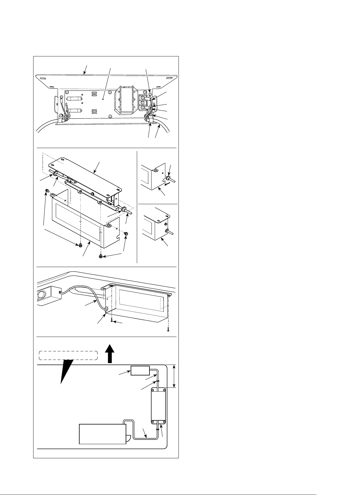
2-6-3. Installing the reactor box
* For the EU-type models, install the reactor box that is supplied with the sewing machine.
❽
❼
❾
❼
Undersurface of table
❸
❸
❷
❽
❶
❾
Operator's side
❹
❺
❶
A
C
B
❻
❽
1) Connect the terminals of power cord ❶ of the
SC-950(951) to reactor-box PCB asm. ❷ and
to reactor box mounting plate ❸.
Connect brown wire A to the rst connector
and blue wire B to the third connector respec-
tively from the top of terminal block on the
reactor box PCB asm. using screws. Connect
green/yellow wire C to reactor box mounting
plate ❸ with earth setscrew ❹.
2) Attach cable clip ❺ to the power cord of SC-
950(951). Attach the power cord together with
the cable clip to reactor box mounting plate ❸
with cable clip setscrew ❻.
3) Attach cord bushes ❽ to input/output cables
❶ and ❼ of the reactor box. Attach both bush-
es in the same manner.
4) Attach reactor box cover to reactor box
mounting plate ❸ with four reactor-box cover
setscrews ❾.
At this time, x cord bushes ❽ attached to
input/output cables ❶ and ❼ in the concave
section on reactor box cover to eliminate a
gap between reactor box and cover .
5) Install reactor box on the table stand with
four accessory wood screws at the position
that is approximately 200 mm away from the
front end of table stand.
Adjust the installing position according to the
size of table stand so that the reactor box does
not protrude from the edge of table stand.
6) Fix input/output cables ❶ and ❼ of reactor
box on the table stand using accessory cord
staple .
At this time, take care not to cross the input-
and output-cables.
Power box
SC-950(951)
❶
❼
200 mm
– 7 –
Page 12
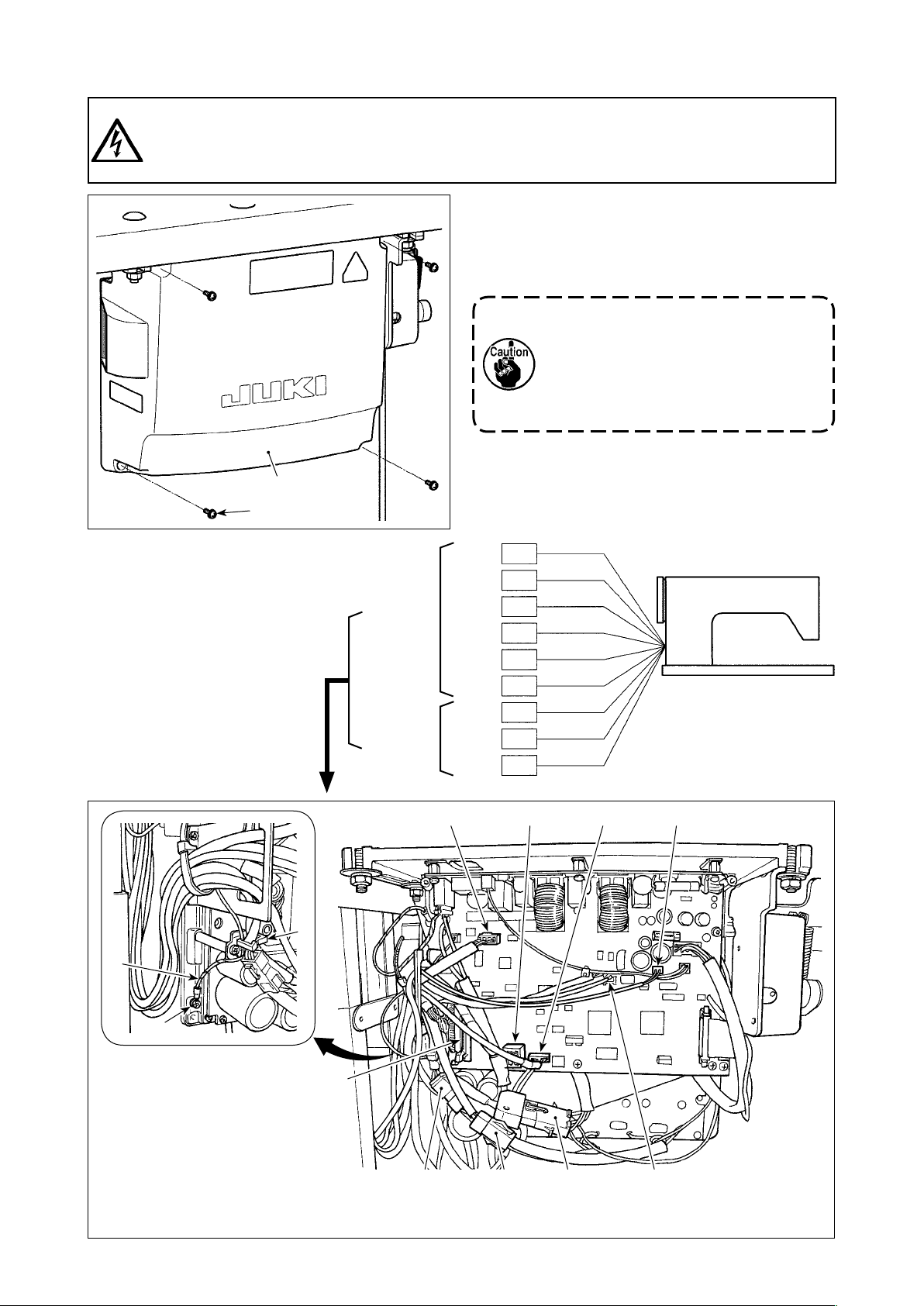
2-7. Connecting the cords
DANGER :
1. To prevent personal injuries caused by electric shock hazards or abrupt start of the sewing
machine, carry out the work after turning OFF the power switch and a lapse of 5 minutes or more.
2. To prevent accidents caused by unaccustomed work or electric shock, request the electric expert
or engineer of our dealers when adjusting the electrical components.
❶
❷
1) Loosen four setscrews ❷ of control box cover ❶.
Remove control box cover ❶.
2) Connect the cords to the respective connectors
on CTL PWB, PWR PWB. (Fig. 1)
Securely x the cords to be connected
to CN20, CN21 and CN22 with cable
clamp ❸.
Check the connector markers of
CN21 and CN22 to prevent improper
connection.
3) Fix the ground wire ❹ on position A of the control
box with a screw. (Fig. 2)
❹
❸
CTL PWB
PWR PWB
CN30
CN32
CN36
CN37
CN38
CN63
CN20
CN21
CN22
CN37
9P
40P
4P
4P
15P
2P
4P
6P
6P
CN30
White
Gray
White
White
White
Black
White
White
White
CN38 CN63
A
Fig. 2
CN32
– 8 –
CN22
CN20CN21
CN36
Fig. 1
Page 13
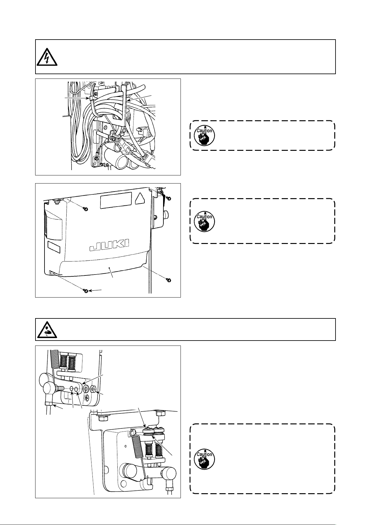
2-8. Handling the cords
DANGER :
1. To prevent personal injuries caused by electric shock hazards or abrupt start of the sewing
machine, carry out the work after turning OFF the power switch and a lapse of 5 minutes or more.
2. To prevent accidents caused by unaccustomed work or electric shock, request the electric expert
or engineer of our dealers when adjusting the electrical components.
❷
➡
A
❶
1) Bring the cords under the table into the control
box.
2) Put the cord brought into the control box through
cord exit plate ❶ and x cable clip band ❷.
Arrange the cord so that it is not tensed
or hitched even when the machine head
is tilted. (See A section.)
3) Install control box cover ❸ with four setscrews ❹.
For the purpose of preventing the cord
breakage, take care not to allow the
cords to be caught between the control
box and control box cover ❸ when
attaching the latter.
❸
❹
2-9. Attaching the connecting rod
WARNING :
To protect against possible personal injury due to abrupt start of the machine, be sure to start the
following work after turning the power off and a lapse of 5 minutes or more.
❷
❸
❶
B
A
❹
❺
1) Fix connecting rod ❶ to installing hole B of pedal
lever ❷ with nut ❸.
2) Installing connecting rod ❶ to installing hole A
will lengthen the pedal depressing stroke, and the
pedal operation at a medium speed will be easier.
3) The pressure increases as you turn reverse depressing regulator screw ❹ in, and decreases as
you turn the screw out.
1. If the screw is excessively loosened,
the spring will come off. Loosen the
screw to such an extent that the top
of the screw can be observed from
the case.
2. Whenever you have adjusted the
screw, be sure to secure the screw by
tightening metal nut ❺ to prevent the
screw from loosening.
– 9 –
Page 14
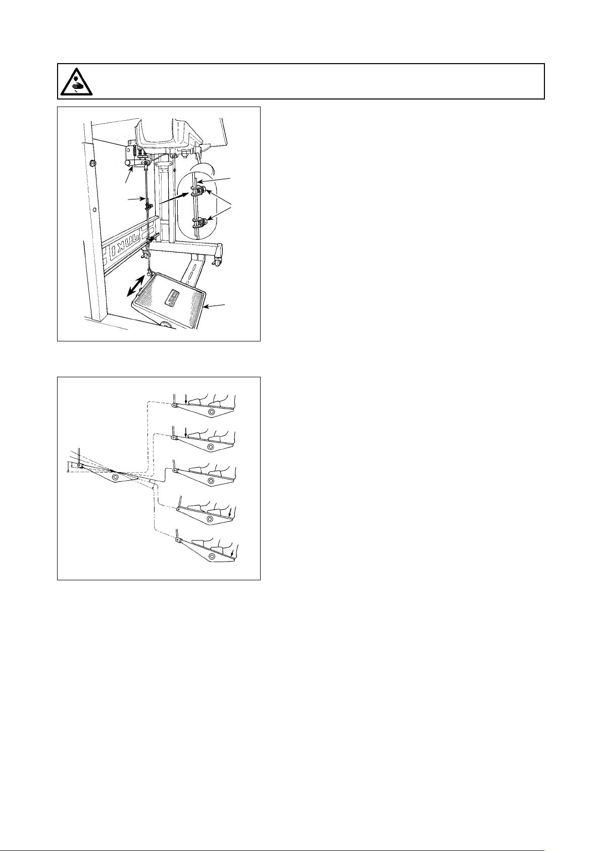
2-10. Adjustment of the pedal
WARNING :
Turn OFF the power before starting the work so as to prevent accidents caused by abrupt start of the
sewing machine.
2-10-1. Installing the connecting rod
1) Move pedal ❸ to the right or left as illustrated by the
arrows so that motor control lever ❶ and connecting rod
❷ are straightened.
❶
❷
2-11. Pedal operation
❸
❷
❹
E
A
B
C
D
2-10-2. Adjusting the pedal angle
1) The pedal tilt can be freely adjusted by changing the
length of the connecting rod ❷.
2) Loosen adjust screw ❹, and adjust the length of connecting rod ❷.
The pedal is operated in the following four steps :
1) The machine runs at low sewing speed when you lightly
depress the front part of the pedal. B
2) The machine runs at high sewing speed when you further
depress the front part of the pedal. A (If the automatic
reverse feed stitching has been preset, the machine runs
at high speed after it completes reverse feed stitching.)
3) The machine stops (with its needle up or down) when you
reset the pedal to its original position. C
4) The machine trims threads when you fully depress the
back part of the pedal. E
* When the auto-lifer (AK device) is used, one more op-
erating switch is provided between the sewing machine
stop switch and thread trimming switch.
The presser foot goes up when you lightly depress the
back part of the pedal D, and if you further depress the
back part, the thread trimmer is actuated.
When starting sewing from the state that the presser foot
has been lifted with the Auto-lifter and you depress the
back part of the pedal, the presser foot only comes down.
• If you reset the pedal to its neutral position during the au-
tomatic reverse feed stitching at seam start, the machine
stops after it completes the reverse feed stitching.
• The machine will perform normal thread trimming even
if you depress the back part of the pedal immediately
following high or low speed sewing.
• The machine will completely perform thread trimming
even if you reset the pedal to its neutral position immedi-
ately after the machine started thread trimming action.
– 10 –
Page 15
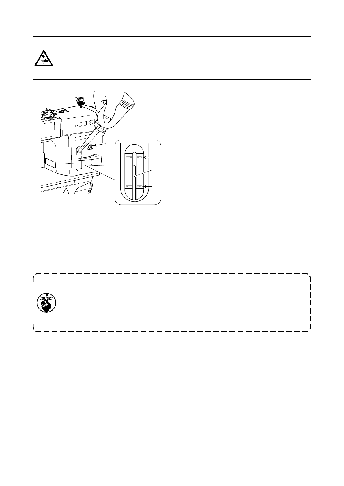
2-12. Lubrication
WARNING :
1. Do not connect the power plug until the lubrication has been completed so as to prevent accidents
due to abrupt start of the sewing machine,
2. To prevent the occurrence of an inammation or rash, immediately wash the related portions if oil
adheres to your eyes or other parts of your body.
3. If oil is mistakenly swallowed, diarrhea or vomitting may occur. Put oil in a place where children
cannot reach.
❷
❶
A
❸
B
Fill the oil tank with oil for hook lubrication before
operating the sewing machine.
1) Remove oil hole cap ❶ and ll the oil tank with
JUKI NEW DEFRIX OIL No.1 (part number : MD-
FRX1600C0) or JUKI CORPORATION GENUINE
OIL 7 (part number : 40102087) using the oiler
supplied with the machine.
2) Fill the oil tank with the oil until the top end of
oil amount indicating rod ❸ comes between the
upper engraved marker line A and the lower
engraved marker line B of oil amount indicating
window ❷.
If the oil is lled excessively, it will leak from the
air vent hole in the oil tank or proper lubrication
will be not performed. In addition, when the oil is
vigorously lled, it may overow from the oil hole.
So, be careful.
3) When you operate the sewing machine, rell oil if
the top end of oil amount indicating rod ❸ comes
down to the lower engraved marker line B of oil
amount indicating window ❷.
1. When you use a new sewing machine or a sewing machine after an extended period of
disuse, use the sewing machine after performing break-in at 2,000 sti/min or less.
2. For the oil for hook lubrication, purchase JUKI NEW DEFRIX OIL No. 1 (part number :
MDFRX1600C0) or JUKI CORPORATION GENUINE OIL 7 (part number : 40102087).
3. Be sure to lubricate clean oil.
4. Do not operate the machine with the oil hole cap ❶ removed. Never remove cap ❶ from the
oil inlet in any case other than oiling. In addition, take care not to lose it.
– 11 –
Page 16
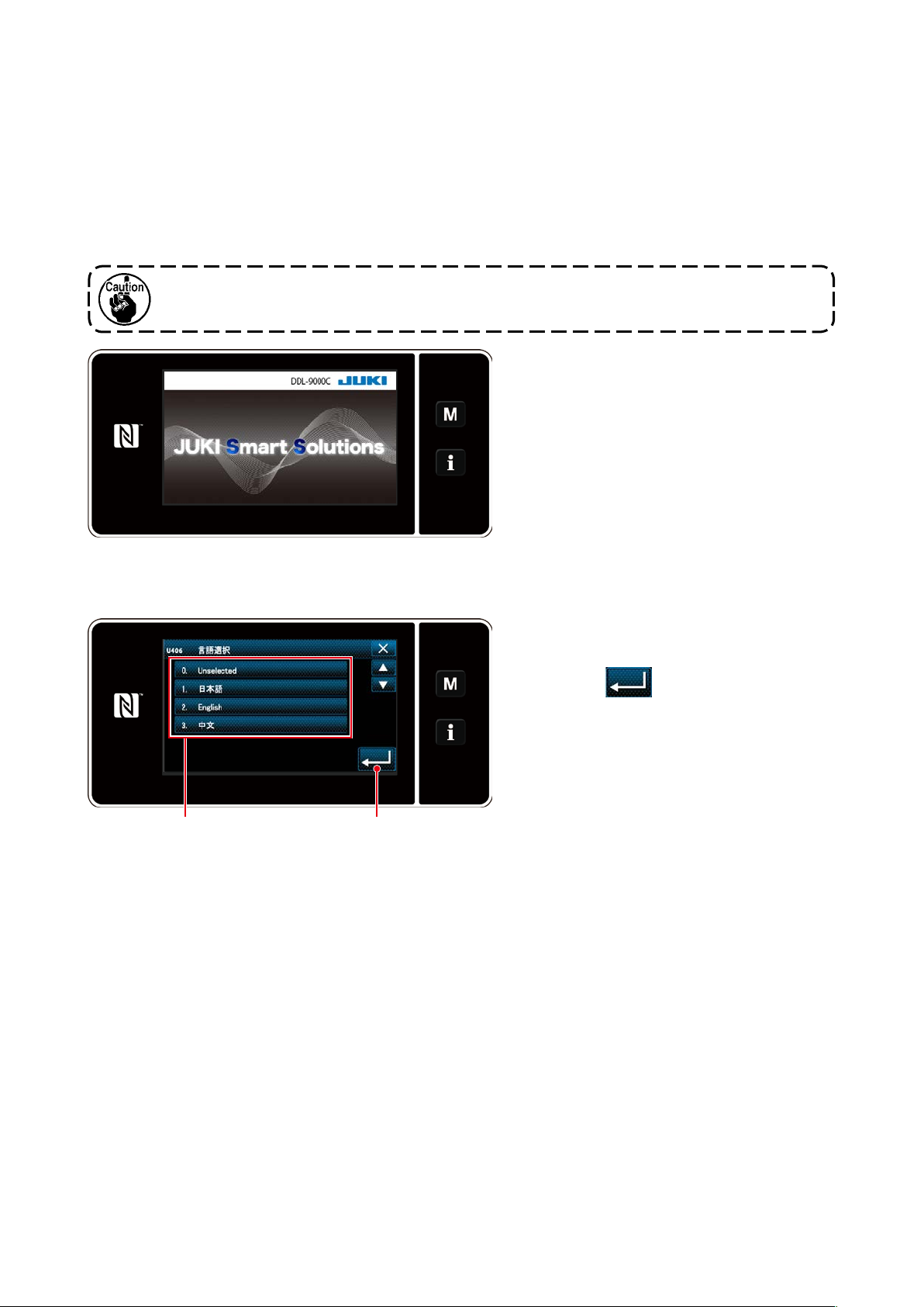
2-13. How to use the operation panel (Basic explanation)
2-13-1. Selection of the language (operation to be done at rst)
Select the language to be displayed on the operation panel when you turn ON the power to your sewing
machine for the rst time after the purchase. Note that, if you turn the power OFF without selecting the
language, the language selection screen will be displayed every time you turn ON the power to the sew-
ing machine.
Turning ON the power switch
①
Be aware that the needle bar moves automatically. The needle bar can also be set so that it
does not move automatically. Refer to "4-5. List of memory switch data" p. 62 for details.
Firstly, the welcome screen is displayed
on the panel. Then, the language selection
screen is displayed.
<Welcome screen>
Selecting the language
②
Select the language you want to use and
press corresponding language button ❶.
Then, press
❷
.
This determines the language to be dis-
played on the panel.
❷❶
<Language selection screen>
The language to be displayed on the operation panel can be changed using the memory switch U406.
Refer to "4-5. List of memory switch data" p. 62 for details.
– 12 –
Page 17
Setting the clock
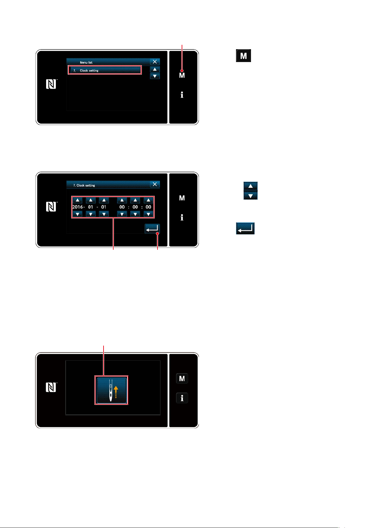
③
❸
<Mode screen>
1. Press
❸
.
The "mode screen" is displayed.
2. Select the "7. Clock setting".
The "clock setting screen" is displayed.
3. Enter year/month/day/hour/minute/sec-
ond with
❹
.
The time entered is displayed in 24-hour
notation.
4. Press
to conrm the clock set-
❺
<Clock setting screen>
Retrieval of the origin
④
❻
ting. Then, the current screen returns to
❺❹
the previous screen.
Press ❻ to bring the origin retrieval needle
bar to its upper position.
* In the case "U090 Initial operation upper
position stop function" is set to "1", the
screen shown on the left is not displayed,
but the needle bar automatically goes up
to its upper position.
<Origin retrieval screen>
– 13 –
Page 18
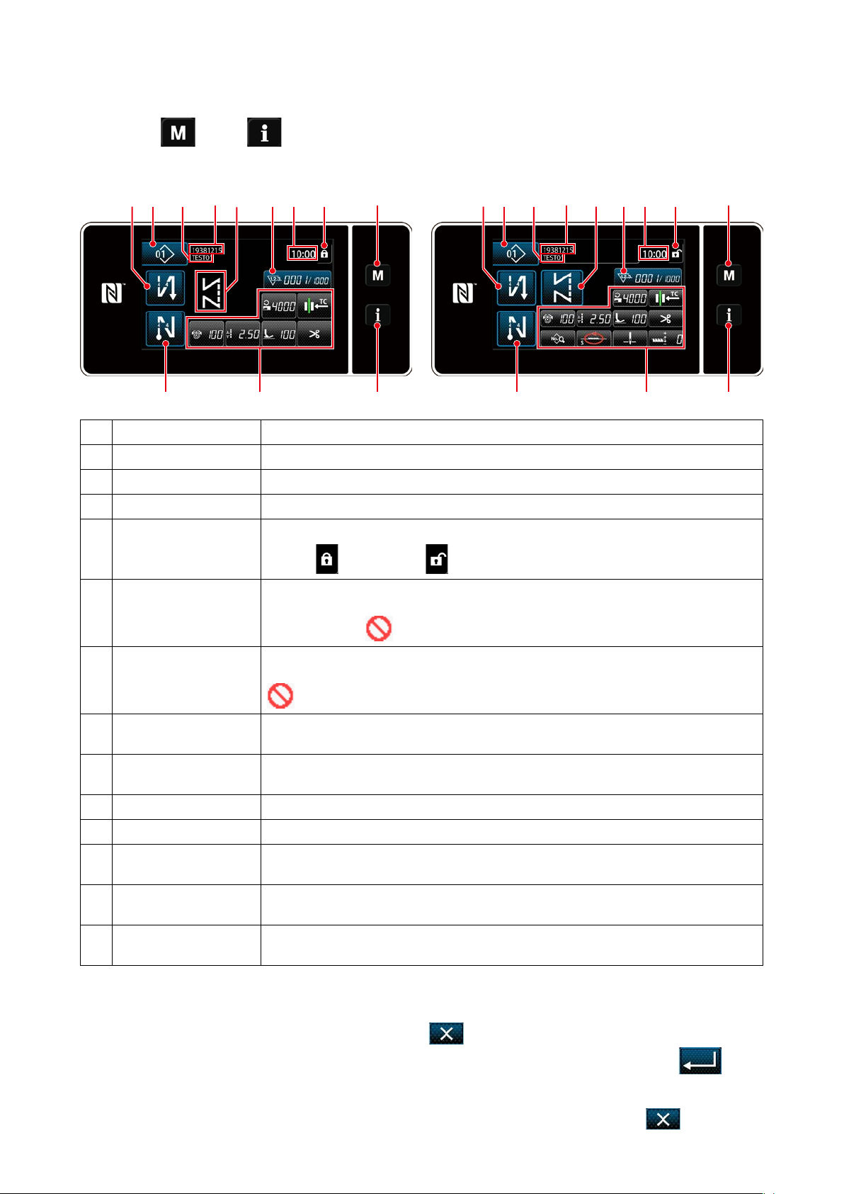
2-13-2. Names and functions of the panel keys
Changeover between the operator mode and the maintenance personnel mode is carried out by
*
pressing
❶
and
simultaneously.
❷
<Operator mode> <Maintenance personnel mode>
❺ ❼
❽ ❾ ❹ ❶❸
Switch/display Description
Mode key This switch is used for displaying the menu screen.
❶
Information key This switch is used for displaying the information screen.
❷
Sewing pattern No. button
❸
Simplied screen lock
❹
button
This switch is used for displaying the number of the sewing pattern.
This button is used for displaying the simplied lock status of the screen on it.
Locked:
❹ ❶❸
❷❻
Unlocked:
❺ ❼
❽ ❾
❷❻
Sewing-start re-
❺
verse-feed stitch button
Sewing-end re-
❻
verse-feed stitch button
Part number In the case the part number/process display is selected with U404, the part number is
❼
Process/comment In the case the part number/process display is selected with U404, the process is dis-
❽
Clock display The time set on the sewing machine is displayed in this eld in 24-hour system.
❾
Sewing pattern display The selected sewing pattern is displayed in this eld.
Customization button 1 A selected function can be allocated to and registered with this button. Initially, the
Customization buttons 2
- 7
Customization buttons 2
- 11
This switch is used for changing the ON/OFF status of the reverse feed stitching at the
beginning of sewing. When reverse feed stitching at the beginning of sewing is placed
in the OFF state,
This switch is used for changing the ON/OFF status of reverse feed stitching at the end
of sewing. When reverse feed stitching at the end of sewing is placed in the OFF state,
mark is displayed at the upper left of the button.
displayed. In the case the comment display is selected, the comment is displayed.
played. In the case the comment display is selected, the comment is displayed.
sewing counter has been factory-allocate and -registered.
A selected function can be allocated to and registered with this button.
A selected function can be allocated to and registered with this button.
mark is displayed at the upper left of the button.
* Conrmation of data
To change the pattern number, press Sewing pattern No. button ❸.
Select the sewing pattern you want to use. Then, press
to conrm your choice.
For the setting items of the Memory switch or sewing pattern, change the target data and press
conrm the change.
After the setting data on the number of stitches of reverse-feed stitching or the number of stitches of
multi-layer stitching has been changed, the changed setting data is conrmed by pressing .
– 14 –
to
Page 19
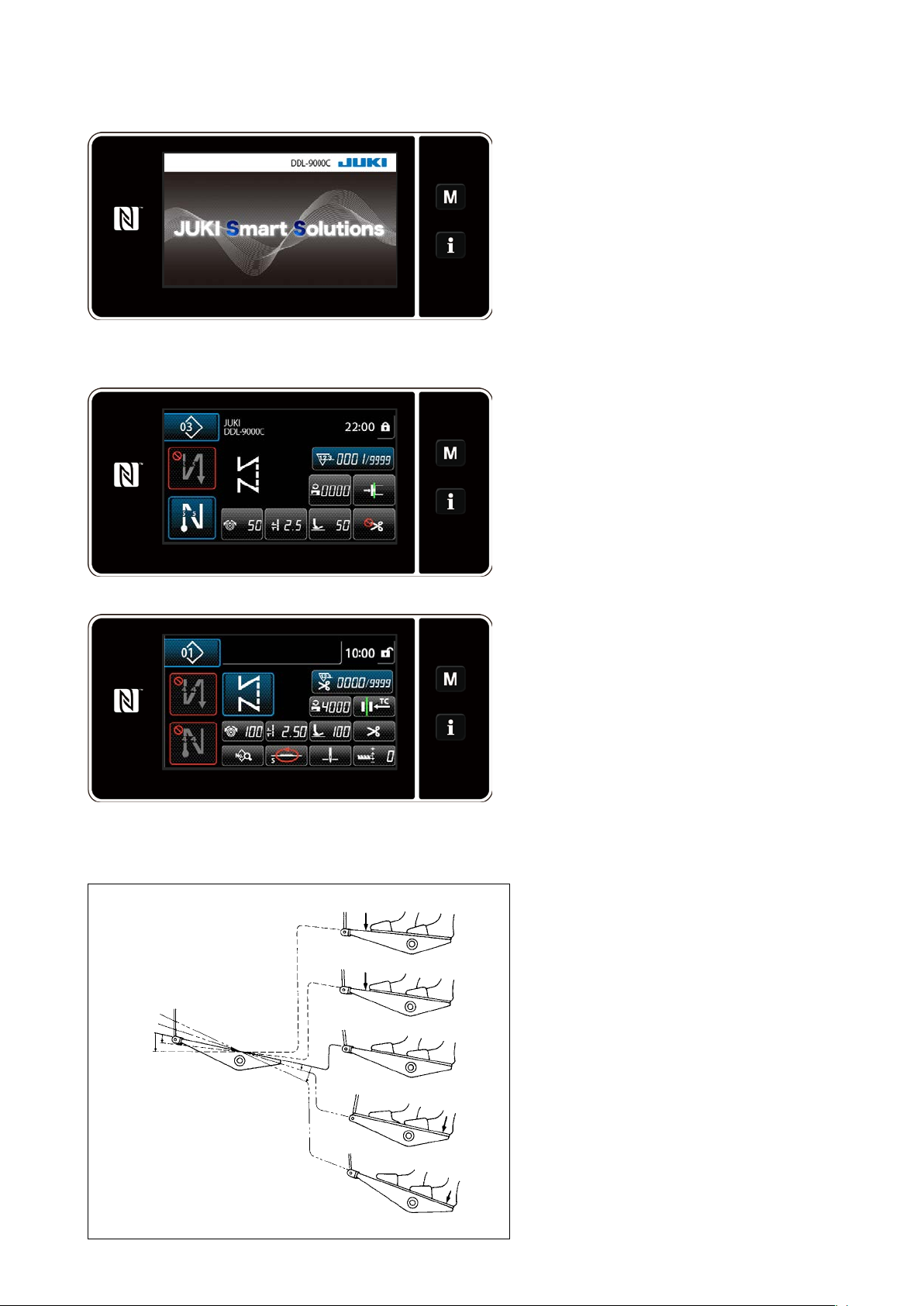
2-13-3. Basic operation
Turning ON the power switch
①
Selecting a sewing pattern
②
<Sewing screen (Operator mode)>
When you turn ON the power switch, the
welcome screen is displayed.
The sewing screen is displayed.
Select a sewing pattern.
・
Refer to
"4-2. Sewing patterns" p. 33
for details.
Congure settings of each function which
・
is assigned according to "8-10. Key cus-
tomization" p. 132.
Set up functions for the selected sewing
・
pattern.
Refer to
"4-2-5. Editing the sewing
patterns" p. 42 and "4-2-6. List of
pattern functions" p. 44 for details.
<Sewing screen (Maintenance personnel mode)>
Starting sewing
③
When you depress the pedal, the sewing
machine starts sewing.
Refer to "2-11. Pedal operation" p. 10.
– 15 –
Page 20
3. PREPARATION BEFORE SEWING
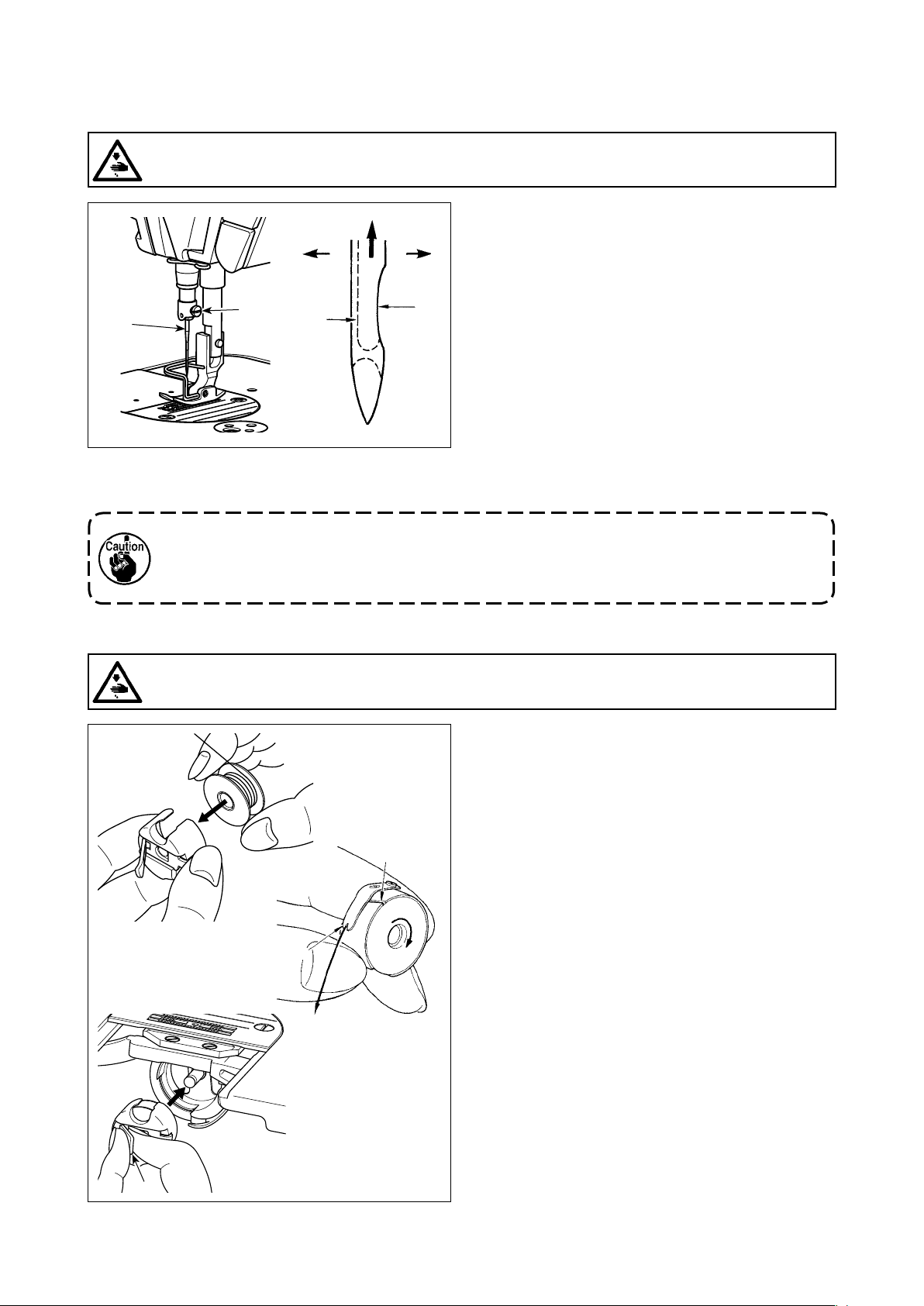
3-1. Attaching the needle
WARNING :
Turn OFF the power before starting the work so as to prevent accidents caused by abrupt start of the
sewing machine.
Use the specied needle for the machine. Use the
proper needle in accordance with the thickness of
D
❶
❷
C
4) Securely tighten screw ❷.
5) Check that long groove C of the needle is facing exactly to the left in direction D.
When polyester lament thread is used, if the indented part of the needle is tilted toward
operator's side, the loop of thread becomes unstable. As a result, hangnail of thread or thread
breakage may occur. For the thread that such phenomenon is likely to occur, it is effective to
attach the needle with its indented part slightly slanting on the rear side.
B
A
thread used and the kinds of the materials.
1) Turn the handwheel until the needle bar reaches
the highest point of its stroke.
2) Loosen screw ❷, and hold needle ❶ with its in-
dented part A facing exactly to the right in direction B.
3) Insert the needle fully into the hole in the needle
bar in the direction of the arrow until the end of
hole is reached.
3-2. Removing/tting the bobbin case
WARNING :
Turn OFF the power before starting the work so as to prevent accidents caused by abrupt start of the
sewing machine.
A
B
C
1) Turn the handwheel to lift the needle above the
throat plate.
2) Install the bobbin in the bobbin case so that the
thread wound direction is clockwise.
3) Pass the thread through thread slit A of the bobbin case, and pull the thread in direction C. By
so doing, the thread will pass under the tension
spring and come out from notch B.
4) Check that the bobbin rotates in the direction of
the arrow when thread is pulled.
5) Pinching latch D of the bobbin case with ngers,
t the bobbin case in the hook.
D
– 16 –
Page 21
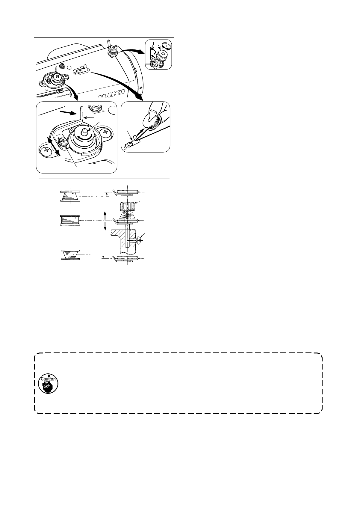
3-3. Winding the bobbin thread
D
C
A
❹
B
❷
❶
E
F
❸
❼
❻
❻
❺
❻
❽
1) Insert the bobbin deep into the bobbin winder
spindle ❶ until it will go no further.
2) Pass the bobbin thread pulled out from the spool
rested on the right side of the thread stand fol-
lowing the order as shown in the gure on the
left. Then, wind clockwise the end of the bobbin
thread on the bobbin several times. (In case of
the aluminum bobbin, after winding clockwise the
end of the bobbin thread, wind counterclockwise
the thread coming from the bobbin thread ten-
sion several times to wind the bobbin thread with
ease.)
3) Press the bobbin winding lever ❷ in the direction
of A and start the sewing machine. The bobbin
rotates in the direction of B and the bobbin thread
is wound up. The bobbin winder spindle ❶ auto-
matically as soon as the winding is nished.
4) Remove the bobbin and cut the bobbin thread
with the thread cut retainer ❸.
5) When adjusting the winding amount of the bobbin thread, loosen setscrew ❹ and move bobbin
winding lever ❷ to the direction of C or D. Then
tighten setscrew ❹.
To the direction of C : Decrease
To the direction of D : Increase
6) In case that the bobbin thread is not wound evenly on the bobbin, remove the handwheel, loosen screw ❺
and adjust the height of bobbin thread tension ❽.
• It is the standard that the center of the bobbin is as high as the center of thread tension disk ❻.
• Adjust the position of thread tension disk ❻ to the direction of E when the winding amount of the bobbin
thread on the lower part of the bobbin is excessive and to the direction F when the winding amount of
the bobbin thread on the upper part of the bobbin is excessive.
After the adjustment, tighten screw ❺.
7) To adjust the tension of the bobbin winder, turn the thread tension nut ❼.
1. When winding the bobbin thread, start the winding in the state that the thread between the
bobbin and thread tension disk ❻ is tense.
2. When winding the bobbin thread in the state that sewing is not performed, remove the
needle thread from the thread path of thread take-up and remove the bobbin from the hook.
3. There is the possibility that the thread pulled out from the thread stand is loosened due to
the inuence (direction) of the wind and may be entangled in the handwheel. Be careful of
the direction of the wind.
– 17 –
Page 22
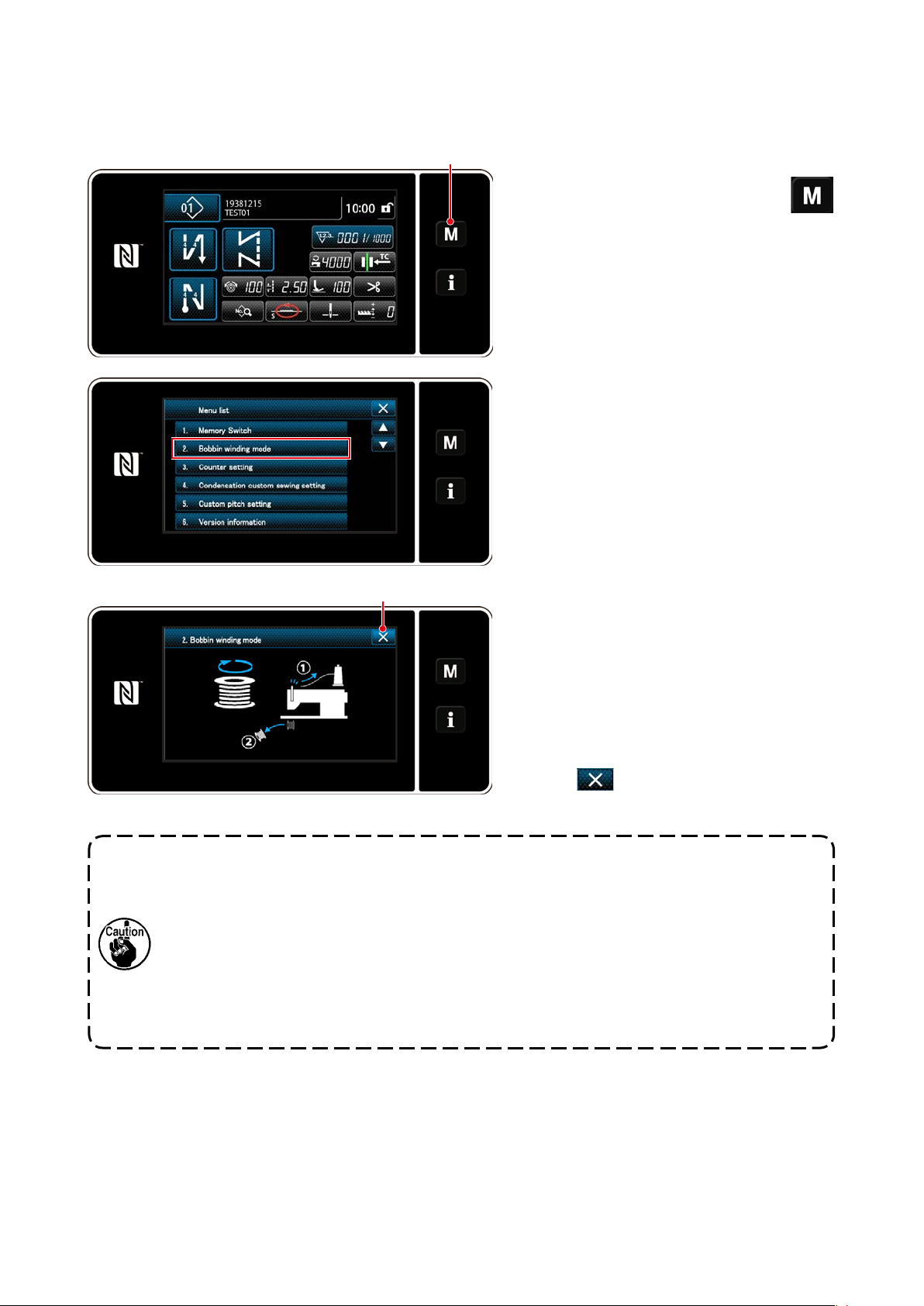
[Bobbin winding mode]
To wind a bobbin only or to check the oil quantity in the hook, the bobbin winding mode should be used.
Depress the pedal to start winding a bobbin.
❶
1) Display the mode screen by pressing
❶.
2) Select the "2. Bobbin winding mode".
❷
3) The sewing machine mode is changed over
to the "Bobbin winding mode".
The sewing machine runs with its presser
foot up when the pedal is depressed. In this
state, a bobbin can be wound. The sewing
machine runs only as long as the pedal is
depressed.
When ❷ is pressed, the sewing ma-
chine exits from the "Bobbin winding mode".
1. When winding the bobbin thread, start the winding in the state that the thread between the
bobbin and thread tension disk ❻ is tense.
2. Remove the needle thread from the thread path of thread take-up and remove the bobbin
from the hook.
3. There is the possibility that the thread pulled out from the thread stand is loosened due to
the inuence (direction) of the wind and may be entangled in the handwheel. Be careful of
the direction of the wind.
4. The speed of the sewing machine under the bobbin winding mode is equal to the one which
has been set for the machine head.
– 18 –
Page 23
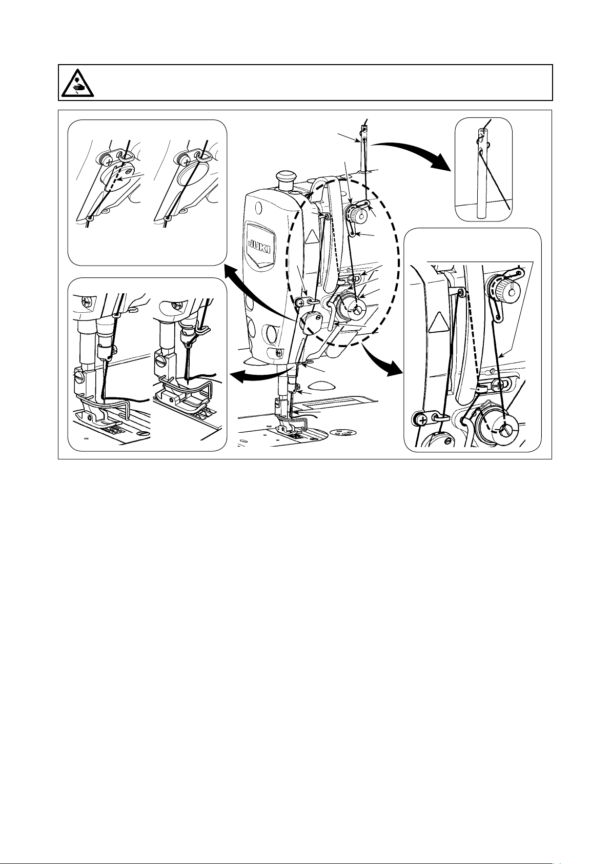
3-4. Threading the machine head
WARNING :
Turn OFF the power before starting the work so as to prevent accidents caused by abrupt start of the
sewing machine.
"NB type" "0B type"
B
(Note)
Be sure to pass the thread
through the section B.
"S type" "H type"
❾
❶
❸
❼
❹
❷
(Note)
Do not pass this thread
through section A.
❽
❻
❺
A
– 19 –
Page 24
3-5. Thread tension
❸
B
❶
A
3-5-1. Adjusting the thread tension No. 1
tension
1) Turn thread tension No. 1 nut ❶ clockwise
(in direction A), to shorten the thread length
remaining on the needle after thread trimming or counterclockwise (in direction B),
to lengthen the thread length.
❷
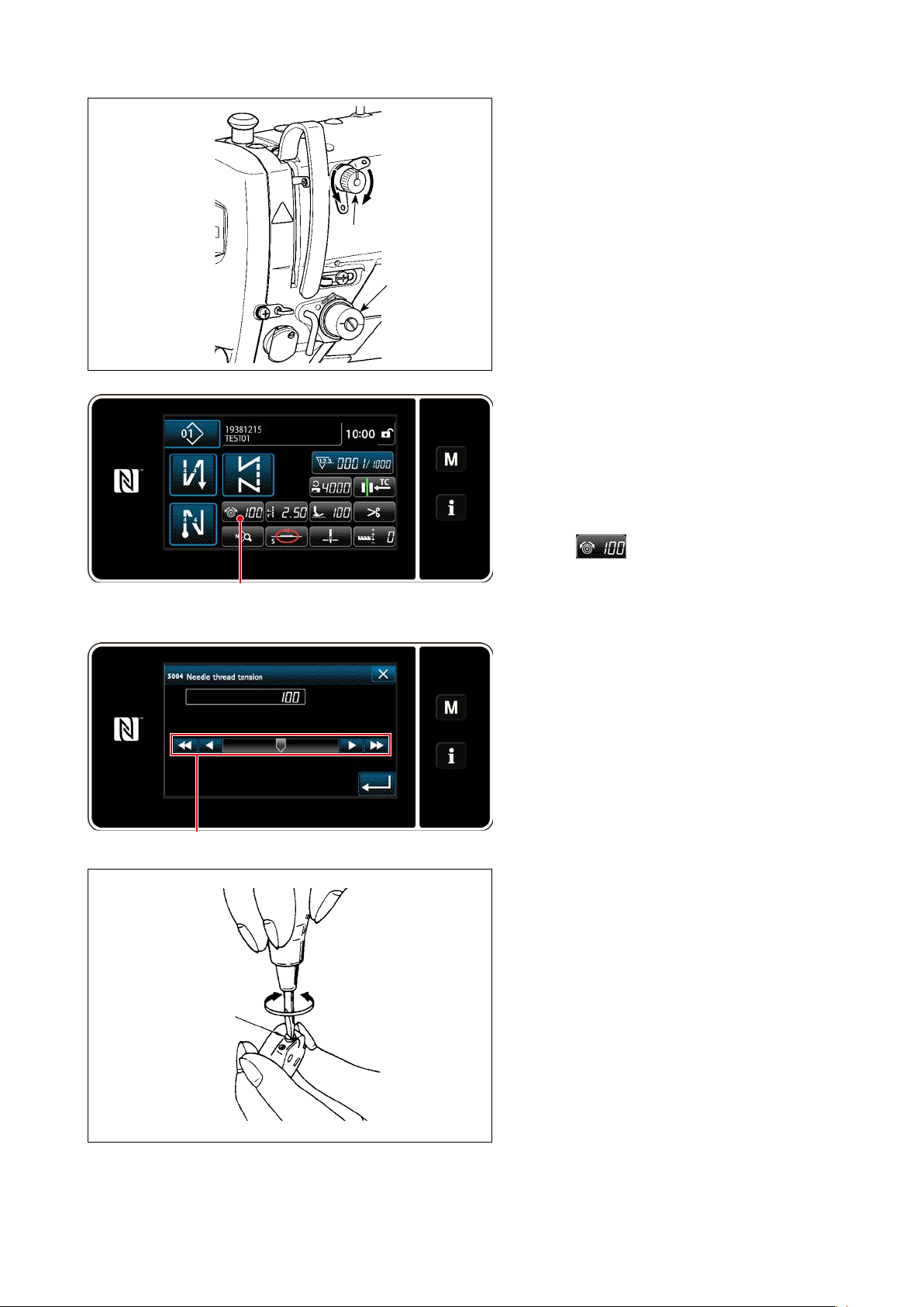
3-5-2. Adjusting the needle thread ten-
sion (Active tension)
Active tension ❷ permits setting of the needle
thread tension on the operation panel accord-
ing to each sewing condition. In addition, the
data can be stored in memory.
1) Press ❸ to display the needle
thread tension input screen. (The numeric
value displayed on the screen is the current
needle thread tension value.)
❹
❺
C
D
2) Change the needle thread tension as desired by pressing ❹.
3) There is a setting range of 0 to 200.
When the set value is increased, the ten-
sion becomes higher.
* When the set value is 60 at the time of stan-
dard delivery, the thread tension is adjusted
to 0.59 N (spun thread #60). (Reference)
(When thread tension No. 1 is released.)
3-5-3. Adjusting the bobbin thread ten-
sion
1) Turn tension adjusting screw ❺ clockwise
(in direction C) to increase or counterclockwise (in direction D) to reduce the bobbin
thread tension.
– 20 –
Page 25
3-6. Presser foot (Active presser device)
WARNING :
Do not place anything under the presser foot when turning the power ON. If the power is turned ON
while placing something under the presser foot, the sewing machine displays E910.
If the power to the sewing machine is turned ON while the material, etc. is placed under the
presser foot, the presser stepping motor will generate a specic sound during origin retrieval.
It should be noted that this phenomenon is not a fault.
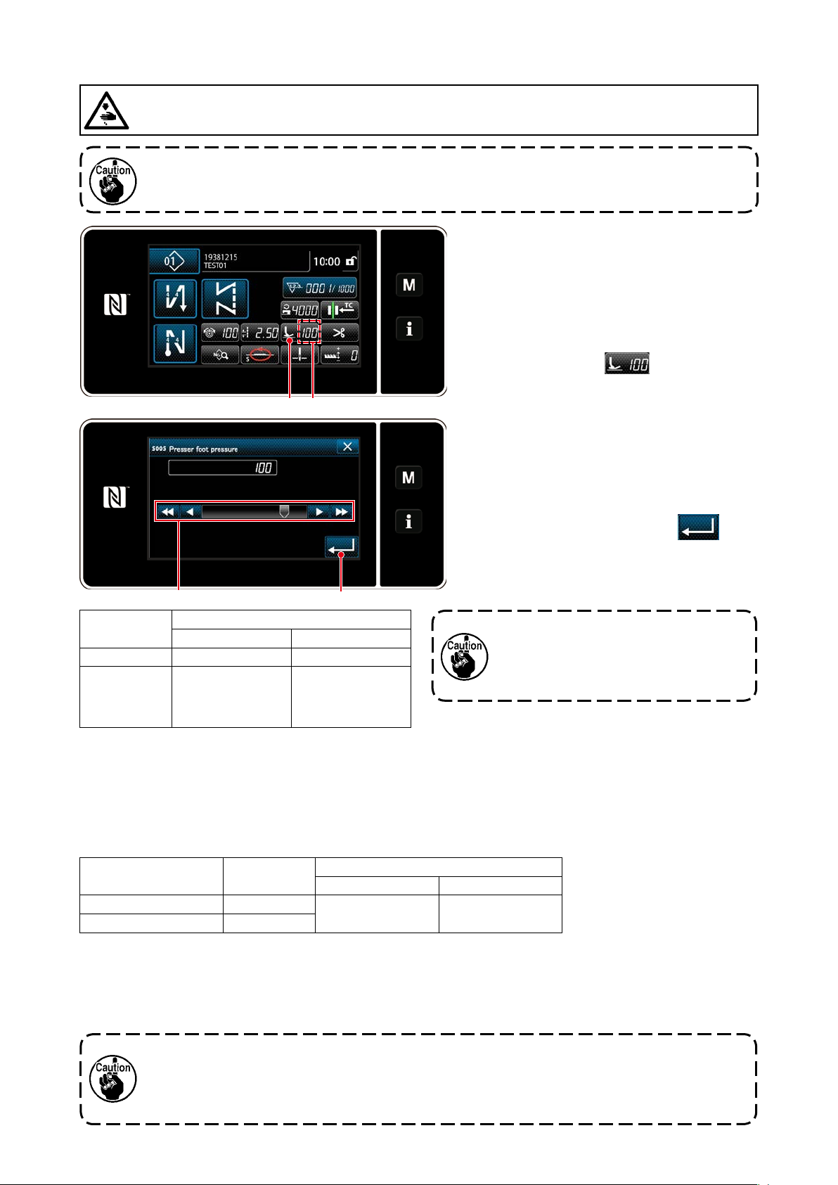
❶ A
3-6-1. Presser foot pressure
The presser foot pressure is displayed in
section A on the panel. (Example of display :
100)
[How to change]
1) Display the presser foot pressure entry
screen by pressing ❶.
2) Change the presser foot pressure as desired by pressing ❷. (Range of input values
on the panel is from -350 to 200.)
* Refer to the following for a rough indica-
tion of the input value on the panel and
the presser foot pressure.
3) Conrm your entry by pressing ❸.
Then, the sewing screen is displayed.
❷
Input value on
the panel
0 Approx. 10 N (1 kg) Approx. 30 N (3 kg)
100
(Factory-set-
ting at the time
of shipment)
Presser foot pressure (Reference)
S type H type
Approx. 40 N (4 kg) Approx. 60 N (6 kg)
❸
1. To avoid personal injury, never put
your ngers under the presser foot.
2. Be aware that the presser foot
pressure varies when the presser
foot or the throat plate is changed.
3-6-2. Micro-lifter function
Sewing while lifting the presser foot by very small amount is enabled by inputting a negative value on the
panel. The micro-lifter function helps reduce slippage and damage of the material in the case of sewing
raised fabric such as velvet.
* Refer to the table shown below for a rough indication of the relation among the value input on the panel,
the presser foot height and the presser foot pressure.
Input value on the panel
0 0 mm
-350 Approx. 4 mm
*1 The presser foot height 0 mm means the state the sole of presser foot comes in contact with the top surface
of throat plate.
*2 The presser foot pressure becomes constant by inputting a negative value on the panel.
*3 The presser foot pressure varies when the presser foot or the throat plate is changed.
*4 Range of input values on the panel is from -350 to 200.
Presser foot
height
Presser foot pressure (Reference)
S type H type
Approx. 10 N (1 kg) Approx. 30 N (3 kg)
1.
Be sure to input a positive value on the operation panel in the case the micro-lifter function is not
used. If not, the presser foot is slightly raised and the feed dog is unable to provide a sufcient
efciency of feed.
2.
In the case of using the micro-lifter function, the efciency of feed is likely to be insufcient. To
achieve the sufcient efciency of feed, reduce the sewing speed or help feed the material by hand.
– 21 –
Page 26
WARNING :
Turn OFF the power before starting the work so as to prevent accidents caused by abrupt start of the
sewing machine.
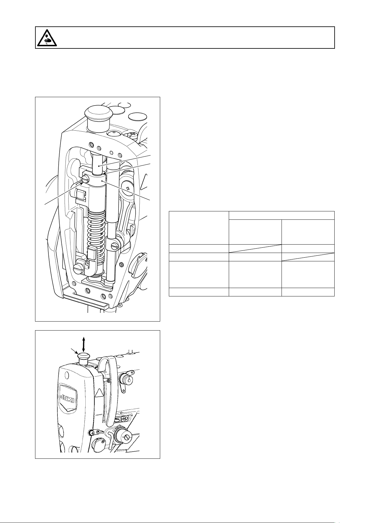
3-6-3. Changing the initial value of presser foot pressure
If you want to change the initial value of presser foot pressure, it is possible to change the initial presser foot
pressure by changing the mounting position of presser bar position bracket (upper) ❹.
Carry out adjustment according to the sewing process as needed basis.
[How to adjust]
1) Turn OFF the power to the sewing machine.
2) Remove the face plate.
3) Loosen presser bar position bracket (upper) clamping
screw ❺. Adjust the vertical position of presser bar position bracket (upper) ❹ using marker line B on presser
❻
B
bar ❻ as reference.
* Adjust the orientation of presser bar position bracket
(upper) ❹ so that it is in parallel with the face plate.
4) After the completion of adjustment, tighten presser bar
position bracket (upper) clamping screw ❺ and attach
❺
❹
the face plate.
❻
Position of presser bar
position bracket (upper) ❹ with respect
to marker line B on
presser bar ❻
4 mm above Approx. 0 N (0 kg)
1 mm above Approx. 0 N (0 kg)
0 (just beneath the
marker line)
(Factory-setting at the
time of shipment)
1 mm below Approx. 20 N (2 kg) Approx. 40 N (4 kg)
Presser foot pressure (Reference)
S type H type
Approx. 10 N (1 kg) Approx. 30 N (3 kg)
3-6-4. Manual lifter
The presser foot can be manually lifted/lowered by moving
presser bar cap ❻ up and down while the power to the sew-
ing machine is in the OFF state.
Use this manual lifting feature when replacing the gauge or
adjusting the needle entry area.
– 22 –
Page 27
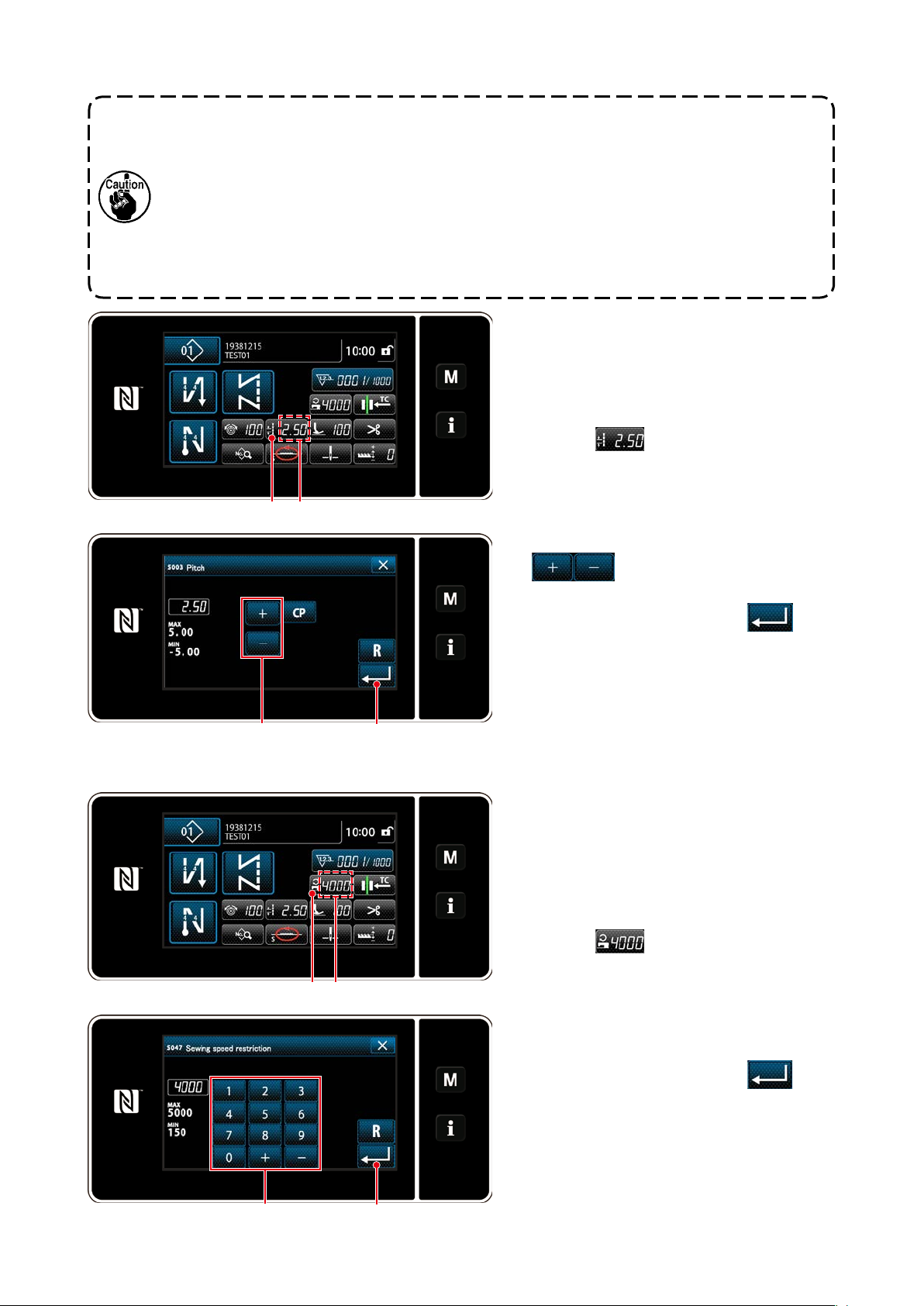
3-7. Adjusting the stitch length
1. There may be the cases where the feed amount of the operation panel and the actual sewing
pitch are different from each other in case of the use in the state other than the standard
delivery or material used. Compensate the pitch in accordance with the sewing product.
2. Be aware that interference between the throat plate and feed dog can occur depending on
the gauge used. Be sure to check the clearance in the gauge to be used. (The clearance
must be 0.5 mm or more.)
3. When you have changed the stitch length, feed dog height or feed timing, run the sewing
machine at a low speed to make sure that the gauge does not interfere with the changed
part.
❶ A
Stitch length is displayed in section A on the
panel. (Example of display : 2.50 mm)
[How to adjust]
1) Display the stitch pitch entry screen by
pressing ❶.
❷ ❸
3-8. Changing the sewing speed
❶ A
2) The value displayed is changed by pressing
❷. (In increments of 0.05 mm ;
Input range : -5.00 to 5.00)
3) Conrm your entry by pressing ❸.
Then, the sewing screen is displayed.
The sewing speed is displayed in section A
on the panel. (Example of display : 4,000 sti/
min)
[How to change]
1) Display the sewing speed entry screen by
pressing ❶.
2) Change the sewing speed as desired by
pressing ten keys ❷.
3) Conrm your entry by pressing ❸.
Then, the sewing screen is displayed.
❸❷
– 23 –
Page 28
3-9. LED hand light
WARNING :
In order to protect against personal injury due to unexpected start of the sewing machine, never
bring hands near the needle entry area or place foot on the pedal during the adjustment of intensity
of the LED.
❶
* This LED is intended to improve operability
of the sewing machine and is not intended for
maintenance.
The sewing machine is provided as standard with an
LED light which illuminates the needle entry area.
Intensity adjustment and turn-off of the light is carried out by pressing switch ❶. Every time the switch
is pressed, the light is adjusted in intensity in ve
steps and is turned off in turn.
[Change of intensity]
1
Bright⇒...... Dim⇒O
⇒
...... 4
⇒
5
1
⇒
ff⇒Bright
In this way, every time the switch ❶ is pressed, the
hand lamp status is changed in repetition.
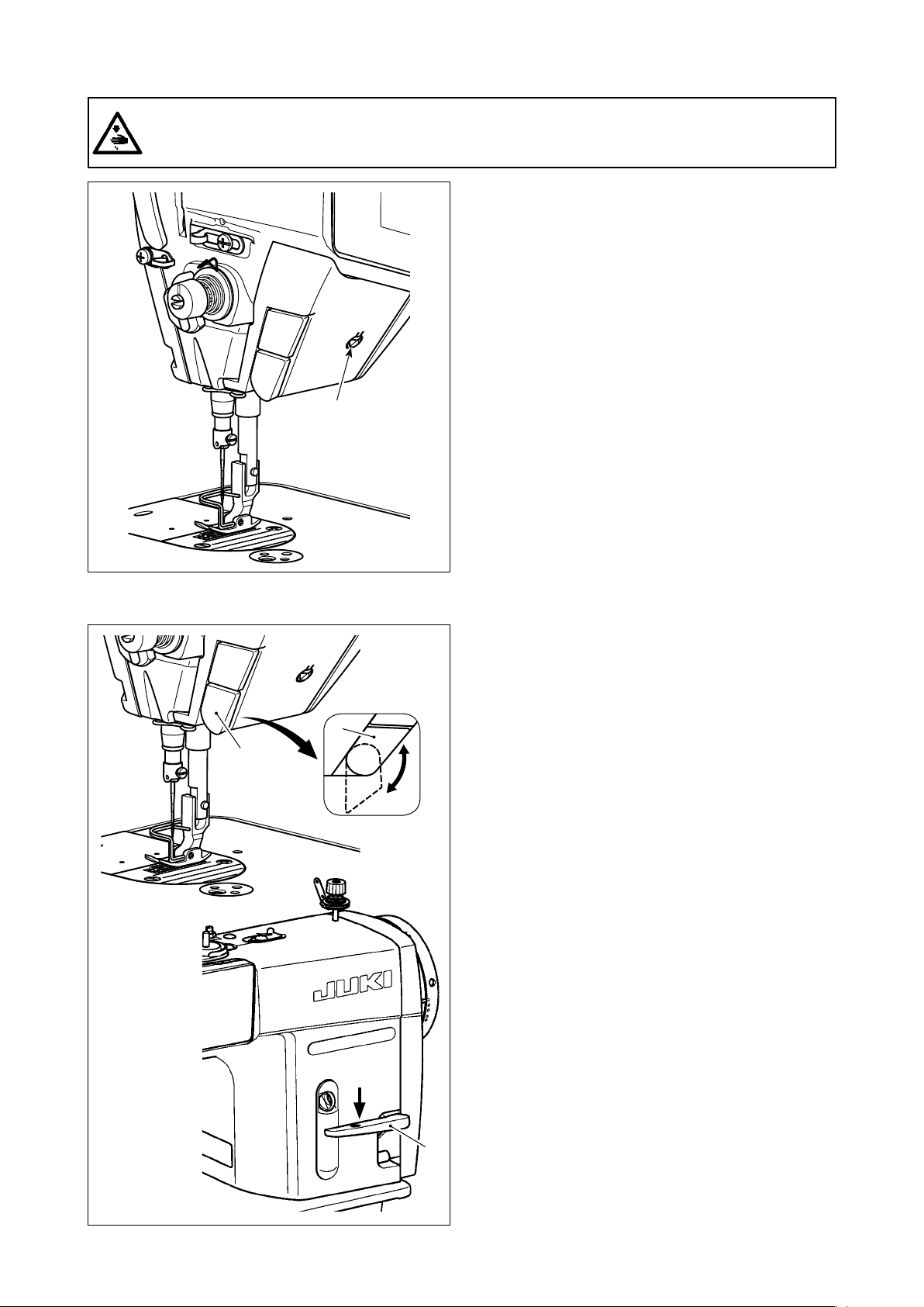
3-10. Reverse feed stitching
❶
❶
Fig. 1
[One-touch type reverse feed stitching mecha-
nism]
The one-touch type reverse feed switch ❶ is
pressed, the machine performs reverse feed stitch-
ing.
The machine resumes normal feed stitching the
moment the switch lever is released.
[Reverse feed stitching by means of the reverse
feed lever]
Length of the seam sewn by feeding the material in
the normal or reverse direction of feed can be controlled by operating reverse feed lever ❷.
[Adjusting the position of one-touch type reverse
feed switch]
One-touch type reverse feed switch ❶ can be used
at two different positions by turning it. (Fig. 1)
❷
– 24 –
Page 29
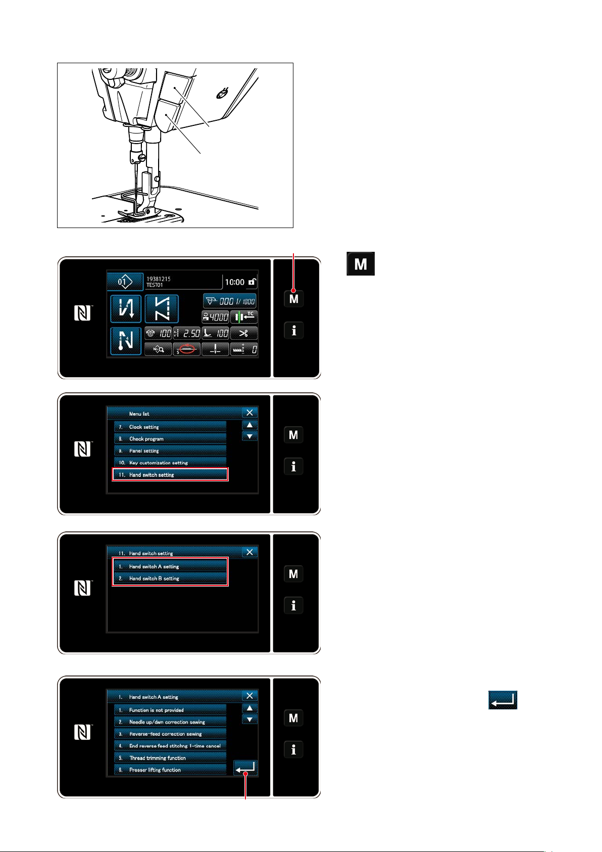
3-11. Custom switch
Various operations can be carried out by operating
custom switch B.
* It is also possible to assign an operation to custom
B
A
switch A.
The initial values are as follows:
Custom switch A
: Input of reverse feed
stitching switch
Custom switch B
: One-touch changeover
switch
❶
1)
The "mode screen" is displayed.
held pressed for three second.
❶
2) Select the "11. Hand switch setting".
3) Select the switch to be set.
4) Select the function item which is to be as-
❷
– 25 –
signed to the switch, and press
❷.
Page 30
[Description of operations of the custom switch]
Function item
1 Optional input function is not provided
2 Needle up / down compensating stitching
3 Back compensating stitching
4 Function of canceling once reverse feed stitching at
the end of sewing
5 Thread trimming function
6 Presser foot lifting function
7 One stitch compensating stitching
8 Material edge sensor input
9 Function of prohibiting depressing front part of pedal
10 Function of prohibiting thread trimming output
11 Low speed command input
12 High speed command input
13 Needle lifting function
14 Reverse feed stitching switch input
15 Soft start switch input
16 One-shot speed command switch input
17 Backward one-shot speed command switch input
18 Safety switch input
19 Automatic reverse feed stitching cancellation/addition
switch
20 Sewing counter input
21 One-touch type changeover switch
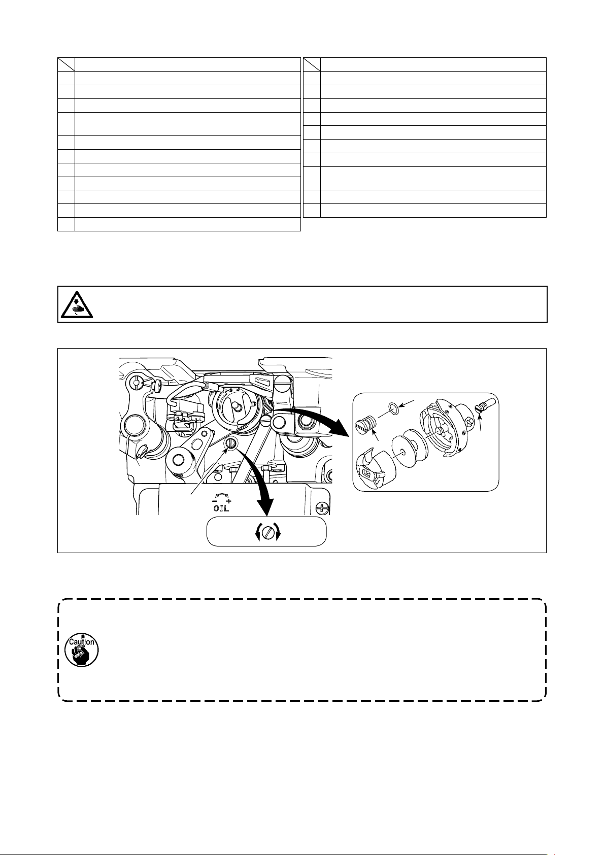
3-12. Adjusting the amount of oil (oil splashes) in the hook
WARNING :
Be extremely careful about the operation of the machine since the amount of oil has to be checked
by turning the hook at a high speed.
3-12-1. Adjusting the amount of oil in the hook
Function item
❹
❷
❶
Decrease
❸
Increase
Tighten (turn clockwise) oil amount adjustment screw ❶ to increase the amount of oil in the hook, or loosen
(turn counterclockwise) to decrease it.
"When using RP hook (hook for dry head) for DDL-9000C-FMS type"
1. Remove hook driving shaft oil wick setscrew ❷ and attach hook driving shaft stopper screw
❸ (part number : 11079506) and rubber ring ❹ (part number : RO036080200).
2. Loosen oil amount adjustment screw ❶ up to the minimum so as to reduce the oil amount in
the hook. However, do not completely stop the oil and be careful not to allow oil adjustment
screw ❶ to come off.
3. Never drain the oil in the oil tank even when RP hook (hook for dry head) is used.
– 26 –
Page 31

3-12-2. How to conrm the amount of oil (oil splashes)
Position to conrm the amount of oil (oil splashes)Amount of oil (oil splashes) conrmation paper
25 mm
Approx.
Hook
Hook driving shaft front bushing
Approx. 70 mm
* Use any paper available regardless of
the material.
3 to 10 mm
Bed
Oil splashes
conrmation paper
Closely t the paper against
the wall surface of the bed.
* Place the amount of oil (oil splashes) conrmation
paper under the hook and keep it from the hook by
3 to 10 mm to conrm the amount.
* In the case of measuring the oil quantity in the hook, measure it under the "Bobbin winding mode".
Refer to "3-3. Winding the bobbin thread [Bobbin winding mode]" p.18 for the bobbin winding
mode.
* When carrying out the procedure described below in 2), conrm the state that the needle thread
from the thread take-up lever to the needle and the bobbin thread are removed, the presser foot is
lifted and the slide plate is removed. At this time, take extreme caution not to allow your ngers to
come in contact with the hook.
1) If the machine has not been sufciently warmed up for operation, make the machine run idle for approxi-
mately three minutes. (Moderate intermittent operation)
2) Place the amount of oil (oil splashes) conrmation paper under the hook while the sewing machine is in
operation.
3) Conrm that oil exists in the oil tank.
4) Conrmation of the amount of oil should be completed in ve seconds. (Check the period of time with a
watch.)
3-12-3. Sample showing the appropriate amount of oil
Appropriate amount of oil (small) Appropriate amount of oil (large)
Splashes of oil from the hook
• DDL-9000C-FMS : 0.5 to 1 mm
• DDL-9000C-FSH : 1 to 3 mm
Splashes of oil from the hook
• DDL-9000C-FMS : 1 to 1.5 mm
• DDL-9000C-FSH : 2 to 4 mm
1) The state given in the gure above shows the appropriate amount of oil (oil splashes). It is necessary
to nely adjust the amount of oil in accordance with the sewing processes. However, do not excessively
increase/decrease the amount of oil in the hook. (If the amount of oil is too small, the hook will be seized
(the hook will be hot). If the amount of oil is too much, the sewing product may be stained with oil.)
2) Check the oil amount (oil splashes) three times (on the three sheets of paper), and adjust so that it should
not change.
– 27 –
Page 32

3-13. Adjusting the thread take-up spring and the thread take-up stroke
"DDL-9000C-FMS" "DDL-9000C-FSH"
❾
❽
A
B
❻
C
D
❶
❸
❷
❽
❻
A
B
❾
❶
❸
❷
F
❺
❶
❹
E
G
H
(1) Adjusting the stroke of thread take-up spring ❶
1) Loosen setscrew ❷.
2) Turn tension post ❸ clockwise (in direction A), the stroke of the thread take-up spring will be increased,
and turn the post ❸ counterclockwise (in direction B), the stroke will be decreased.
(2) Adjusting the pressure of thread take-up spring ❶
1) Loosen setscrew ❷, and remove thread tension (asm.) ❺.
2) Loosen tension post setscrew ❹.
3) Turn tension post ❸ clockwise (in direction A), the pressure will be increased, and turn the post ❸ counterclockwise (in direction B), the pressure will be decreased.
* Standard state of the thread take-up spring ❶
The engraved marker line ❻ on the machine arm is almost aligned with the top of thread take-up spring. (It is
necessary to adjust in accordance with materials and processes.)
To check how the thread take-up spring works, draw out the needle thread in direction F after
having adjusted the thread take-up spring pressure to check whether the thread take-up spring
exerts force to the thread up to the last moment (state G) just before the thread comes out
from E. If the spring fails to exert force to the spring until the last moment (state H), decrease
the thread take-up spring pressure. In addition, the stroke of the thread take-up spring is
excessively small, the spring does not work properly. For the general fabrics, a stroke of 10 to
13 mm is proper.
(3) Adjusting the thread take-up stroke
1) When sewing heavy-weight materials, move thread guide ❽ to the left (in direction C) to increase the
length of thread pulled out by the thread take-up.
2) When sewing light-weight materials, move thread guide ❽ to the right (in direction D) to decrease the
length of thread pulled out by the thread take-up.
* Standard state of the thread guide
• DDL-9000C-FMS : Marker line ❾ on the thread guide aligns with the center of the setscrew.
• DDL-9000C-FSH : Marker line ❾ on the thread guide aligns with the center of the marker line on the ma-
chine arm.
– 28 –
Page 33

4. HOW TO USE THE OPERATION PANEL
4-1. Explanation of the sewing screen (when selecting a sewing pattern)
On the sewing screen, the shape and set values of the currently-sewn sewing pattern are displayed.
The display and button operation differ according to the selected sewing pattern.
Note that the sewing screen shows two different displays, i.e., the sewing pattern display and the counter display.
Refer to "4-3. Counter function" p. 56 for the description of the counter display.
There are two different screen display modes; i.e., <Operator mode> and <Maintenance personnel
mode>.
The mode can be changed over between the operator mode and the maintenance personnel mode by
simultaneously pressing
❶
and
❷
.
(1) Sewing screen (when selecting a sewing pattern)
A sewing pattern can be selected with
. Four different stitch shapes are available as
shown below.
<Operator mode>
❺ ❼❽ ❾
Free stitching pattern
(Operator mode)
❹ ❶❸
❷❻
<Maintenance personnel mode>
❺ ❾
Constant-dimension sewing pattern
(Operator mode)
❹ ❶❸
❷❻
Multi-layer stitching pattern
(Operator mode)
– 29 –
Polygonal-shape stitching pattern
(Operator mode)
Page 34

Free stitching pattern
(Maintenance personnel mode)
Constant-dimension sewing pattern
(Maintenance personnel mode)
Multi-layer stitching pattern
(Maintenance personnel mode)
Polygonal-shape stitching pattern
(Maintenance personnel mode)
Switch/display Description
Mode key This switch is used for displaying the menu screen.
❶
Level 1 is displayed by pressing this switch in the normal manner. Level 2 or
Level 3 is displayed by keeping this switch held pressed for three seconds or
more for the former or six seconds or more for the latter.
The mode is changed over between the operator mode and maintenance
personnel mode by pressing the Mode key and the Information key simultaneously.
Information key This switch is used for displaying the information screen.
❷
Level 1 or Level 2 is displayed by pressing this switch in the normal manner
for the former or by keeping it held pressed for three seconds or more for the
latter.
The mode is changed over between the operator mode and maintenance
personnel mode by pressing the Information key and the Mode key simultaneously.
Sewing pattern No.
❸
button
Simplied screen
❹
lock button
Sewing pattern list screen is displayed. The currently-selected sewing pattern
number is displayed on this button. (P01 – P99)
This is button is used for changing over the operation status of buttons displayed on the screen between enable and disable.
This button is used for displaying the simplied lock status of the screen on it.
Locked:
Unlocked:
Once the button operation is locked using the simplied screen lock button,
operation of the buttons displayed on the screen, excluding this button will be
disabled.
– 30 –
Page 35

Switch/display Description
Sewing-start re-
❺
verse-feed stitch
button
Sewing-end re-
❻
verse-feed stitch
button
Part number The part number is displayed in this eld.
❼
Process/comment The process or comment is displayed in this eld.
❽
Clock display The time set on the sewing machine is displayed in this eld in 24-hour sys-
❾
* Pattern shape button Selected sewing pattern is displayed on this screen.
* Sewing data list but-
ton
Customization button A selected function can be allocated to and registered with this button.
Customization button A selected function can be allocated to and registered with this button.
Customization button A selected function can be allocated to and registered with this button.
* Customization button A selected function can be allocated to and registered with this button.
* Customization button A selected function can be allocated to and registered with this button.
* Customization button A selected function can be allocated to and registered with this button.
Customization button A selected function can be allocated to and registered with this button.
Customization button A selected function can be allocated to and registered with this button.
This switch is used for changing the ON/OFF status of the reverse feed stitching at the beginning of sewing. When reverse feed stitching at the beginning
of sewing is placed in the OFF state,
of the button.
The reverse feed stitching (at start) edit screen is displayed by keeping this
key held pressed for one second.
This button is displayed for free stitching, constant-dimension sewing or
→
polygonal-shape stitching.
This switch is used for changing the ON/OFF status of reverse feed stitching
at the end of sewing. When reverse feed stitching at the end of sewing is
placed in the OFF state,
The reverse feed stitching (at end) edit screen is displayed by keeping this
key held pressed for one second.
This button is displayed for free stitching, constant-dimension sewing or
→
polygonal-shape stitching.
tem.
Four different sewing patterns are available, i.e., free stitching pattern,
constant-dimension sewing pattern, multi-layer stitching pattern and polygonal-shape stitching pattern.
The shape selection screen is displayed by pressing this button.
A selected function can be allocated to and registered with this button.
In the initial state, "sewing data edit screen" is displayed.
Refer to "4-2-6. List of pattern functions" p. 44.
This button has been initially set to the "sewing counter".
Refer to "4-2-6. List of pattern functions" p. 44.
This button has been initially set to the "pitch".
Refer to "4-2-6. List of pattern functions" p. 44.
This button has been initially set to the "sewing speed".
Refer to "4-2-6. List of pattern functions" p. 44.
This button has been initially set to the "correction of feed dog height ".
Refer to "4-2-6. List of pattern functions" p. 44.
This button has been initially set to the "feed locus".
Refer to "4-2-6. List of pattern functions" p. 44.
This button has been initially set to the "stop position of needle bar".
Refer to "4-2-6. List of pattern functions" p. 44.
This button has been initially set to the "needle thread tension".
Refer to "4-2-6. List of pattern functions" p. 44.
This button has been initially set to the "presser foot pressure".
Refer to "4-2-6. List of pattern functions" p. 44.
mark is displayed at the upper left of the button.
mark is displayed at the upper left
– 31 –
Page 36

Switch/display Description
Customization button A selected function can be allocated to and registered with this button.
This button has been initially set to the "prohibition of thread trimming".
Refer to "4-2-6. List of pattern functions" p. 44.
Customization button A selected function can be allocated to and registered with this button.
This button has been initially set to the "feed timing".
Refer to "4-2-6. List of pattern functions" p. 44.
Multi-layer stitching
button
The multi-layer stitching setting screen is displayed by keeping this button
held pressed for one second.
Refer to "4-2-5. Editing the sewing patterns" p. 42.
This button is displayed when multi-layer stitching is selected.
→
Number of stitches This button is used for displaying the number of stitches of constant-dimen-
sion sewing or the number of stitches registered for each step of polygonal-shape stitching.
This button is displayed when constant-dimension sewing or polygo-
→
nal-shape stitching is selected.
Display of the
number of steps of
a polygonal-shape
This button is displayed when constant-dimension sewing or polygonal-shape
stitching is selected (1 to 20).
This button is displayed when polygonal-shape stitching is selected.
→
stitching pattern
* Only in the case the maintenance personnel mode is selected.
– 32 –
Page 37

4-2. Sewing patterns
Patterns which are frequently sewn can be registered as sewing patterns.
Once the patterns are registered as sewing patterns, the desired sewing pattern can be called up only
by selecting its sewing pattern number.
As many as 99 different patterns can be registered as sewing patterns.
4-2-1. Sewing pattern conguration
One sewing pattern consists of four elements, i.e., reverse feed stitching (at start), main stitching, re-
verse feed stitching (at end) and pattern function.
❶
A B
❸
❷
E
CD
Reverse feed stitching (at start) section
❶
Refer to "4-2-3. Reverse feed stitching (at start)
pattern" p. 36.
Main stitching section
❷
Free stitching
・
Constant-dimension sewing
・
Multi-layer stitching
・
Polygonal-shape stitching
・
Refer to "4-2-5. Editing the sewing patterns"
p. 42 and
shape stitching" p. 101.
Reverse feed stitching (at end) section
❸
Refer to "4-2-7. Reverse feed stitching (at end)
pattern" p. 47.
Pattern function
❹
Refer to "4-2-5. Editing the sewing patterns" p.
42.
Pattern No. 1 - No. 99
"8-2. Setting up the polygonal-
– 33 –
Page 38

4-2-2. List of sewing patterns
The list of stored sewing patterns are displayed on the screen. Under the maintenance personnel mode,
sewing patterns can be created, copied and deleted.
A
<Sewing screen (operator mode)>
Pattern list screen: In numerical order
(Operator mode)
❶
❾
Press
on the sewing screen of
A
each mode.
The sewing pattern number list screen is
displayed.
Pattern list screen: In alphabetical order
(Operator mode)
❷
❸
❹
Pattern list screen: In numerical order
(Maintenance personnel mode)
❺ ❻ ❼ ❽
Pattern list screen: In alphabetical order
(Maintenance personnel mode)
– 34 –
Page 39

Name Function
Pattern No. button This button is used for displaying numbers of the registered sewing patterns
❶
and cycle patterns.
(Cycle pattern numbers that are not registered are not displayed.)
When this button is pressed, the sewing pattern is put into the selected
state.
Display range: Sewing pattern numbers 1 to 99 and cycle patterns 1 to 9.
Registered character
❷
button
Sorting button This button is used for sorting the registered patterns in the order of sewing
❸
Rening button This button is used for displaying the rener setting screen.
❹
New sewing pattern
❺
creation button
New cycle pattern
❻
creation button
Pattern copy button This button is used for copying a sewing pattern or cycle pattern and
❼
Pattern delete button This button is used for displaying the pattern deletion conrmation message.
❽
Sewing pattern is displayed and the pattern is put into the selected state by
pressing this button.
pattern number, process, part number or comment.
This button is used for creating a new sewing pattern.
Refer to "8-1-1. Creation of a new pattern" p. 97.
* This button is only displayed under the maintenance personnel mode.
This button is used for creating a new cycle pattern.
Refer to "8-3. Cycle pattern" p. 104.
* This button is only displayed under the maintenance personnel mode.
registering the copied pattern with new number.
Refer to "8-1-2. Copying a pattern" p. 99.
* This button is only displayed under the maintenance personnel mode.
In the case there is only one registered pattern, the pattern cannot be
deleted.
* This button is only displayed under the maintenance personnel mode.
Scroll (up) button This button is used for displaying the previous page.
❾
Scroll (down) button This button is used for displaying the next page.
Close button This button is used for cancelling the selected pattern and displaying the
sewing screen.
Enter button This button is used for conrming the selected pattern and displaying the
sewing screen.
Display of pattern data
being selected
This button is used for displaying data on the pattern that is being selected.
– 35 –
Page 40

4-2-3. Reverse feed stitching (at start) pattern
A stitch shape of the reverse feed stitching (at start) is set by following the steps of procedure described
below.
(1) Enabling the reverse feed stitching (at start) pattern
The sewing-start reverse feed stitching pat-
tern can be operated when the sewing-start
reverse feed stitching function is placed in
the ON state (
mark is not displayed).
If this function is placed in the OFF state,
press the sewing start reverse feed stitch
button to switch off
mark display to en-
able the sewing-start reverse feed stitching
function.
(2) Changing the number of stitches and pitch of reverse feed stitching (at start) pattern (In the
case of operator mode)
Displaying the edit screen for reverse feed stitching (at start)
①
❶
held pressed for one second. The
❶
reverse feed stitching (at start) edit screen
is displayed.
Setting the shape, the number of stitches and pitch of reverse feed stitching (at start)
②
❸❷ ❷
Change the numeric value with
The value you have entered is conrmed by
pressing
. Then, the sewing screen
❸
is displayed.
<Edit screen for reverse feed stitching
(start) (operator mode)>
– 36 –
❷
.
Page 41

"Type of stitch" and "edit item" that can be selected are as follows:
Type of stitch Edit item
Reverse feed stitching
Reverse feed stitching is performed once
at the beginning of sewing.
Condensation
Stitch pitch at the beginning of sewing is
reduced.
Double reverse feed stitching
Reverse feed stitching is performed twice
at the beginning of sewing.
Condensation custom
The number of stitches and pitch of
condensation can be set as desired.
Number of
stitches A
Number of
stitches A
Number of
stitches A
Condensation custom No.
Number of
stitches B
→ →
Pitch
→
Number of
stitches B
→ →
Pitch
Pitch
– 37 –
Page 42

For the maintenance personnel mode
◆
Display the sewing-start reverse-feed stitching edit screen and set up a shape
①
B
❷ ❷
1. Display the sewing-start reverse-feed
stitching edit screen referring to the case
of the operator mode.
2. Change the number of stitches of sew-
ing-start reverse-feed stitching with
.
❷
A EDC
<Sewing-start reverse-feed stitching screen
(maintenance personnel mode)>
Selecting the type of sewing-start reverse-feed stitching (
・
1. Press
❹
<Type of reverse-feed stitching input screen>
Selecting the condensation custom (
・
B
)
2. Press
1. Press
)
A
. Then, the type of
A
reverse-feed stitching input screen
is displayed. Select the desired type
of sewing-start reverse-feed stitch-
ing pattern from four different types;
i.e., reverse-feed stitching (single),
condensation stitching, double re-
verse-feed stitching and Condensa-
tion custom.
to conrm the afore-
❹
mentioned operation and return the
current screen to the sewing-start
reverse-feed stitching screen.
. Then, the conden-
B
❺ ❹
<Condensation custom selection screen>
– 38 –
sation custom selection screen is
displayed.
* In the case the condensation custom
button is not used, mark is
displayed.
2. Press button
to select the conden-
❺
sation custom.
3. Press
to conrm the afore-
❹
mentioned operation and return the
current screen to the sewing-start
reverse-feed stitching screen.
Page 43

Inputting the needle-thread tension value (
・
❼
C
)
1. Press
. Then, the thread
C
tension input screen is displayed.
Input a thread tension (0 to 200) with
button ❻.
❻
<Thread tension input screen>
Inputting the pitch (
・
< Pitch input screen>
❻
D
*
is not displayed when ❼ is
C
selected.
2. Press
to conrm the afore-
❹
mentioned operation and display the
❹
sewing-start reverse-feed stitching
screen.
)
❼
1. Press
. Then, the pitch input
D
screen is displayed. Input a pitch (-5.00
to 5.00) with button ❻.
*
is not displayed when ❼ is
D
selected.
2. Press
to conrm the afore-
❹
mentioned operation and display the
❹
sewing-start reverse-feed stitching
screen.
Inputting the presser foot pressure (
・
❻
<Presser foot pressure input screen>
❼
❹
E
)
– 39 –
1. Press
. Then, the presser
E
foot pressure input screen is dis-
played.
Input a presser foot pressure with but-
ton ❻. (-10 to 200)
*
is not displayed when ❼ is
E
selected.
2. Press
to conrm the afore-
❹
mentioned operation and display the
sewing-start reverse-feed stitching
screen.
Page 44

Applying the changed items
②
❸
<Sewing-start reverse-feed stitching screen
(maintenance personnel mode)>
Press
to conrm the aforementioned
❸
operation and return the current screen to
the sewing screen.
– 40 –
Page 45

4-2-4. Double reverse-feed stitch
Conguring the double reverse-feed stitching pattern shape.
Displaying the double reverse-feed stitching setting screen
①
❶
Keep
on the screen which appears when a double
reverse feed stitching pattern is selected to
display the double reverse feed stitching edit
screen.
<Sewing screen>
Conguring the double reverse-feed stitching pattern shape
②
❷
❸❷
1. Set the number of stitches with
2. Press
held pressed for one second
❶
❷
to conrm the set value
❸
and return the current screen to the sew-
ing screen.
.
<Double reverse-feed stitching edit screen
(operator mode)>
<Double reverse-feed stitching edit screen
(maintenance personnel mode)>
Under the maintenance personnel mode, the
condensation custom can be set in addition
to the aforementioned types of stitching. (In
the case of setting data for using the con-
densation custom)
Set up the condensation custom referring
to "4-2-3. (2) ◆For the maintenance
personnel mode" p.38.
– 41 –
Page 46

4-2-5. Editing the sewing patterns
(1) Edit method (in the case free stitching, constant-dimension sewing or multi-layer stitching is
selected)
* In the case polygonal-shape stitching is selected, refer to
stitching" p. 101.
Displaying the sewing data edit screen
①
On the sewing screen which is displayed in
the case free stitching, constant-dimension
sewing or multi-layer stitching is selected,
press
edit screen.
❶
<Sewing screen>
Editing the sewing pattern
②
❷
On this screen, the pattern functions can be
edited separately.
Refer to "4-2-6. List of pattern functions"
p. 44 for the function items that can be
edited.
Change the respective items and press
"8-2. Setting up the polygonal-shape
to display the sewing data
❶
<Sewing data edit screen>
Performing sewing using the edited sewing pattern
③
<Sewing screen>
to conrm the change.
Press
to display the sewing screen.
❷
Data you have changed is displayed on the
screen.
– 42 –
Page 47

❸
<Number of stitches input screen>
* In the case a constant-dimension sewing
pattern is selected, the number of stitch-
es input screen is displayed by pressing
at the time of setting the number
❸
of stitches. (Only in the case the number
of stitches can be changed)
Refer to
"4-2-8. Teaching function" p.
48 for the teaching function.
❹
❺
* When a multi-layer stitching pattern is
selected, the multi-layer stitching pattern
edit screen is displayed by keeping
held pressed for one second.
❹
1. Set the number of stitches with
❺
.
2. Set the number of times of double re-
❼❺
verse feed stitching with
❺❻
3. Press
to conrm the set value
❼
❻
.
and return the current screen to the sewing screen.
<Multi-layer stitching edit screen>
– 43 –
Page 48

4-2-6. List of pattern functions
(1) Setting items under the pattern sewing mode
Data
No.
S001 Shape Free
S002 Number of stitches/
Number of times
S003 Pitch -5.00 to 5.00 / Custom pitch No.1 to 20 ―
S004 Thread tension 0 to 200
S005 Presser foot pressure -350 to 200
S041 Stop position of needle bar
S042 Thread presser
S043 Prohibition of thread
trimming
Item name Input range
Constant dimension Multi-layered Polygonal shape
― 1 to 2000 1 to 15 ―
―
: Stop with the needle down
: Stop with the needle up
: OFF / : ON
: OFF / : ON
S044 One-shot ―
S045 Thread trimming after one-
shot
S046 Shorter-thread remaining
S047 Limit on sewing speed 150 to U096 ―
S048 Feed locus
S049 Feed timing -30 to 30°
S050 Correction of feed dog
height
S051 Correction value for stitch
pitch of reverse feed
stitching
―
S
: OFF
: ON
: OFF
: ON
: OFF / : ON
/ A
-4 to 8 ―
/ C / B
-5.00 to 5.00
― ―
―
: OFF
: ON
S052 Multi-layered part detection
sensor value
S053 Number of stitches to start
sewing after the detection
of multi-layered part
1000 to 3000
0 to 200
– 44 –
Page 49

Data
No.
Item name Input range
S061 *1Limit on sewing speed 150 to U096 / Common setting
S047
S062 *1Pitch -5.00 to 5.00 / Common setting
S003
S063 *1Thread tension 0 to 200
S064 *1Presser foot pressure -350 to 200
S065 *1Correction of feed dog
-4 to 8 ― -4 to 8
height
S066 *1Feed locus
S
/
A /
C /
B /
S068*2Part number - 24 characters
― 150 to U096
/ Common
setting S047
― -5.00 to 5.00
/ Common
setting S003
―
S
/
A /
C /
B /
S069*2Process - 24 characters
S070*2Comment 50 characters
*1.
This is the one-touch type changeover function. Refer to "4-2-9. One-touch utility changeover function" p. 50.
*2. Only the limited number of characters is displayed.
– 45 –
Page 50

(2) Setting items for the polygonal-shape stitching steps
Step 1
Item name Input range
S071 Number of stitches 1 to 2000
S072 Pitch -5.00 to 5.00 / Custom pitch No.1 to 20
S073 Thread tension 0 to 200
S074 Presser foot pressure -350 to 200
S075 Correction of feed dog height -4 to 8
S076 Stop position of needle bar
: Stop with the needle down
: Stop with the needle up
: Thread trimming
: Continuity
S077 Stop position of presser foot 0 to 15.0 mm
S078 One-shot
: OFF / : ON
S079 Limit on sewing speed 150 to U096
↓
Step 2
* Setting items and the input range are same as those of step 1.
* Step numbers can be set to Step 20.
After you have changed the setting, check to make sure that the feed dog does not come in
contact with the throat plate.
Be aware that the stitch pitch may change if you have changed the locus or the feed dog
height. It is, therefore, necessary to carry out trial stitching rst before using the machine
for production.
– 46 –
Page 51

4-2-7. Reverse feed stitching (at end) pattern
A stitch shape of reverse feed stitching (at end) is set by following the steps of procedure described
below.
(1) Enabling the reverse feed stitching (at end) pattern
The sewing-end reverse feed stitching pat-
tern can be operated when the sewing-end
reverse feed stitching function is placed in
the ON state (
mark is not displayed).
If this function is placed in the OFF state press
the sewing end reverse feed stitch button to
mark display to enable the sew-
❶
switch off
ing-end reverse feed stitching function.
In the case the reverse feed stitching or double reverse feed stitching is selected, number of stitches A
is displayed on the left side and number of stitches B is displayed on the right side on
the case the condensation stitching is selected, only number of stitches A is displayed on
, and in
❶
(display
range: 0 to 99). In the case the condensation custom is selected, the condensation custom number is
displayed on
.
(2) Changing the number of stitches and pitch of reverse feed stitching (at end) pattern
Displaying the edit screen for reverse feed stitching (at end)
①
Keep
held pressed for one sec-
❶
ond. The reverse feed stitching (at end) edit
screen is displayed.
❶
Setting the shape, the number of stitches and pitch of reverse feed stitching (at end)
②
❸❷ ❷
Change the numeric value with
The value you have entered is conrmed by
pressing
. Then, the sewing screen
❸
is displayed.
Press
to select the type of sew-
❹
ing.
❷
.
❹
<Sewing-end reverse feed stitching edit screen>
– 47 –
Page 52

4-2-8. Teaching function
This is the function that enables entry of the number of stitches of a sewing pattern using the actual
number of stitches sewn.
This function screen can be displayed from the sewing data edit screen.
* The teaching function can be used in the case the "constant-dimension sewing" or "polygonal-shape
stitching" is selected.
❶
Press ❶ on the sewing data list screen.
Then, the number of stitches input screen is
displayed.
<Sewing screen (constant-dimension sewing)
(Maintenance personnel mode)>
❶
<Sewing screen (polygonal-shape stitching)
(Maintenance personnel mode)>
(1) How to set (constant-dimension sewing)
❷
<Number of stitches input screen>
Turning ON the teaching function
①
Press
to turn ON the teaching
❷
function.
Starting teaching
②
The input value is set to 0 (zero). De-
press the pedal to start sewing. Count
the number of stitches until the sewing
machine stops.
Conrming the data entered under the
③
teaching mode
Conrm the content of teaching by carry-
ing out thread trimming.
Return the current screen to the sewing
screen (maintenance personnel mode).
– 48 –
Page 53

(2) How to set (polygonal-shape stitching)
Turning ON the teaching function
①
Press
to turn ON the teaching
❷
function.
❷ ❸
<Number of stitches input screen>
Start teaching, and conrm data on a step-by-step basis
②
The input value is set to 0 (zero). Depress the pedal to start sewing. Count the number of stitches
until the sewing machine stops.
1. In the case of starting the teaching by operation on the operation panel
❹
Carry out the step until its end is reached (the
❺
2. In the case of starting the teaching using the pedal
After the completion of sewing steps (the last stitch), depress the back part
of pedal. Then, the data entered for the current step under the teaching
mode is conrmed and the screen is changed to the teaching screen for the
next step.
If no further step to be registered is present, this operation will be disabled.
last stitch is sewn). Then, press
❸
to
conrm the teaching data.
Return the current screen to the sewing
screen (maintenance personnel mode).
Press
on the current step. Press
to conrm the teaching data
❹
to
❺
change the current screen to the number of
stitches input screen for the next step.
If no further step to be registered is present,
this operation will be disabled.
– 49 –
Page 54

4-2-9. One-touch utility changeover function
In the case the one-touch function is assigned to the custom switch, the pitch, sewing speed and feed
dog height can be changed over by pressing the custom switch.
S003 Pitch
S004 Thread tension
S062 One-touch type changeover of pitch
⇔
S063 One-touch type thread tension
⇔
S005 Presser foot pressure ⇔ S064 One-touch type presser foot pressure
S047 Sewing speed
S050 Feed dog height
S048 Feed locus
S061 One-touch type changeover of sewing speed
⇔
S065 One-touch type changeover of feed dog height
⇔
S066 One-touch type changeover of feed locus
⇔
Refer to "3-11. Custom switch" p. 25.
During the one-touch utility changeover, the target data display changes.
– 50 –
Page 55

4-2-10. Registration of a new sewing pattern
A newly-created sewing pattern is registered by following the steps of procedure described below.
Selecting the new-pattern creating function
①
❶
❷
<Sewing pattern management screen>
1. Press
to display the sewing
❶
pattern management screen.
2. Press
❷
.
3. Select the desired sewing shape (free
stitching, constant-dimension sewing,
multi-layer stitching, polygonal shape
stitching).
– 51 –
Page 56

Selecting the new sewing pattern number
②
❸
❹
1. Press
to display the sewing pat-
❸
tern No. registration.
2. Enter the pattern number to be registered
using the numeric keypad.
3. Press
to conrm the pattern
❹
number you have entered.
The sewing pattern management screen
is displayed.
Conrming the data on the created sewing pattern
③
<Sewing screen>
The newly created sewing pattern is dis-
played.
– 52 –
Page 57

4-2-11. Copying a pattern
❶
❷
<Sewing pattern management screen>
1. Press
to display the sewing
❶
pattern management screen.
2. Press
❷
.
❹
3. Input a copy pattern number with the
numeric keypad.
4. Press
to conrm the pattern
❹
number you have entered.
5. The newly created sewing pattern is dis-
played.
– 53 –
Page 58

4-2-12. Narrow-down function
It is possible to select and display sewing pattern(s) which include target characters from the sewing
patterns stored in memory by entering the target characters such as the product number, process or
comment. This function can be used both under the operator mode and maintenance personnel mode.
Selecting the new-pattern creating function
①
❶
<Sewing screen (maintenance personnel mode)>
❷
<Sewing pattern management screen>
1. Press
to display the sewing
❶
pattern management screen.
2. Press
❷
.
– 54 –
Page 59

Select the target pattern to be narrowed down
②
❸ ❼
1. Select sewing patterns from which a
desired pattern is narrowed down using
button
❸
.
2. The character input screen is displayed
by pressing❹.
It is possible to enter a character(s) which
is to be used for narrow-down operation
with the character string button.
❻
❹
<Narrow-down condition setting screen>
❺
3. The entered characters are erased by
pressing button
❺
.
4. The "sewing pattern number list screen" containing only the patterns which include the entered char-
acter(s) are displayed by pressing
5. Narrow-down operation is not carried out by pressing
❻
.
. Then, the "sewing pattern number list
❼
screen" is displayed.
* In the case characters are entered for two or more items on the narrow-down condition setting
screen, only the patterns which satisfy all the entered conditions are displayed. For cycle sewing
patterns, a comment is only used as the narrow-down condition.
– 55 –
Page 60

4-3. Counter function
This function counts sewing in the predetermined unit and gives a visible alarm on the screen when the
preset value is reached.
4-3-1. Displaying the sewing screen under the counter display mode
Three different types of the counter are
available, i.e., the bobbin thread counter, the
sewing counter and the pitch time counter.
4-3-2. Types of the counter
Bobbin thread counter
The bobbin thread counter adds one to its current value every time the sewing machine
sews 10 stitches.
When the preset value is reached, the count-completion screen is displayed.
* Refer to "4-3-4. How to reset the count-completion state" p. 60.
Sewing counter
The sewing counter adds one to its current value every time one stitch shape is sewn.
When the preset value is reached, the count-completion screen is displayed.
* Refer to "4-3-4. How to reset the count-completion state" p. 60.
Pitch time counter
The pitch time counter adds one to its current value every time one stitch shape is sewn.
The target value counter adds one to its current value on the preset pitch-by-pitch basis.
* Refer to "4-3-4. How to reset the count-completion state" p. 60.
– 56 –
Page 61

4-3-3. How to set the counter
Selecting the counter setting
①
❶
1. Display the mode screen by pressing
.
❶
2. Select the "Counter setting".
<Mode screen>
Setting the type of counter, current value of counter and preset value for counter
②
The sewing counter and the bobbin counter should be set following the same procedure.
Current value of counter
Preset value for counterType of counter
1. The counter setting screen is displayed
to enable setting.
2. Press the button of the desired item.
Then, the change screen corresponding
to that item is displayed.
<Counter setting screen>
– 57 –
Page 62

1. Select the desired type of counter.
<Counter type screen>
❷
2. Press
to conrm the type of
❷
counter you have selected.
1. Select the current counter value.
2. Enter with the numeric keypad.
3. Press
to conrm the type of
❷
counter you have selected.
❷
<Current counter value screen>
❷
<Counter set value screen>
1. Select the counter set value.
2. Enter with the numeric keypad.
3. Press
to conrm the type of
❷
counter you have selected.
– 58 –
Page 63

―
Bobbin thread counter
UP counter (adding method):
The bobbin thread counter adds one to its current value every time the sewing
machine sews 10 stitches. When the current value reaches the preset value, the
count-completion screen is displayed.
DOWN counter (subtracting method):
The bobbin thread counter subtracts one from its current value every time the sewing
machine sews 10 stitches. When the current value becomes 0 (zero), the countcompletion screen is displayed.
Disuse of counter:
The bobbin thread counter counts nothing even when the sewing machine performs
sewing. The count-completion screen is, therefore, not displayed.
Sewing counter
UP counter (adding method):
The counter adds one to its current value every time the sewing machine sews one
stitch shape. When the current value reaches the preset value, the count-completion
screen is displayed.
DOWN counter (subtracting method):
The counter subtracts one from its current value every time the sewing machine sews
one stitch shape. When the current value becomes 0 (zero), the count-completion
screen is displayed.
―
―
Disuse of counter:
The sewing counter counts nothing even when the sewing machine performs sewing.
The count-completion screen is, therefore, not displayed.
Pitch time counter
UP counter (adding method):
The counter adds one to its current value every time the sewing machine sews one
stitch shape.
DOWN counter (subtracting method):
The counter subtracts one from its current value every time the sewing machine sews
one stitch shape.
Disuse of counter:
The sewing counter counts nothing even when the sewing machine performs sewing.
The count-completion screen is, therefore, not displayed.
– 59 –
Page 64

Conrming the data entered
③
❸
Conrm the data on counter setting items
<Mode screen>
<Sewing screen (counter)>
you have entered. Then, press
❸
to
return the screen to the mode screen.
When you press
again, the screen
❸
is returned to the sewing screen.
The data on the counter function entered is
displayed.
4-3-4. How to reset the count-completion state
❶
<Count-completion screen>
When the predetermined conditions are
satised during sewing, the count-comple-
tion screen is displayed.
The counter is reset by pressing
❶
Then, the mode is returned to the sewing
mode. In this mode, the counter starts
counting again.
.
– 60 –
Page 65

4-4. Simplied chart of panel displays
Pitch entry screen
Sewing data edit screen
Sewing data edit screen
(Sewing speed)
Sewing screen
Sewing data edit screen
(Feed locus)
Sewing data edit screen
(Feed timing)
Mode screen
Memory
switch
Sewing data edit screen
(Feed dog height correction)
Patten list screen
New pattern creation screen
Reverse feed stitching edit screen
Memory switch type selection screen
Memory switch edit screen
– 61 –
Display all
Page 66

4-5. List of memory switch data
No. Item Setting range Unit
U001 Soft-start function
The initial value differs with the machine head. (0: OFF)
U002 Material edge sensor function
0:Without the material edge detection function / 1:Sewing machine stops
after sewing the preset number of stitches (U004) following the detection of
material edge
U003 Thread trimming function activated by material edge sensor
0:Without the automatic thread trimming function after detection of material
edge / 1:Sewing machine stops and simultaneously carries out automatic
thread trimming after sewing the preset number of stitches (U004) following
the detection of material edge
U004 Number of stitches for material edge sensor
Number of stitches to be sewn after the detection of material edge until the
sewing machine stops.
U007 Bobbin thread count-down unit
0: 10 stitches / 1: 15 stitches / 2: 20 stitches
U008 Reverse feed stitching speed
The initial value differs with the machine head.
The number of revolutions set with this memory switch is given precedence
even if it is lower than the lowest speed by pedal.
U013 Bobbin thread count stop function
0: Sewing machine start prohibition function is disabled even when the
counter completes counting (negative value).
1: When the counter completes counting, the sewing machine start after
thread trimming is prohibited.
2: When the counter completes counting, the sewing machine temporarily
stops and the start of sewing machine after thread trimming is prohibited.
* Note that the prohibition function is disabled in the case the initial value of
counter is 0 (zero).
0 to 9 Stitch
0 to 1
0 to 1
0 to 19 Stitch
0 to 2
150 to 3000 sti/min
0 to 2
ー
ー
ー
ー
U014 Sewing count function
1: Automatic sewing counter / 2: Sewing counter switch input
U021 Presser foot lift when the pedal is in its neutral position
0: Disabled / 1: Enabled
U025 Operation after manual turning (thread trimming)
This memory switch is used for setting the thread trimmer operation after the
sewing machine has moved from its upper/lower stop position by manual
turning of handwheel.
0: Permitted / 1: Prohibited
U030 Middle-of-sewing reverse feed stitching function
Midpoint-of-sewing reverse feed stitching function is set.
0: Without the midpoint-of-sewing reverse feed stitching function / 1: With
the midpoint-of-sewing reverse feed stitching function
U031 Number of stitches of middle-of-sewing reverse feed stitching
Number of midpoint-of-sewing reverse feed stitches is set.
U032 Condition of enabling middle-of-sewing reverse feed stitching while
sewing machine is at rest
Midpoint-of-sewing reverse feed stitching function enable condition
0: Disabled when the swing machine is at rest / 1: Enabled when the sewing
machine is at rest
1 to 2
0 to 1
0 to 1
0 to 1
1 to 19 Stitch
0 to 1
ー
ー
ー
ー
ー
– 62 –
Page 67

No. Item Setting range Unit
U033 Thread trimming activated by middle-of-sewing reverse feed stitching
Thread trimming function after the completion of midpoint-of-sewing reverse
feed stitching is set.
0: Without automatic thread trimming function / 1: With automatic thread
trimming function
U035 Minimum speed of the pedal
The maximum number of revolutions during thread trimming differs with the
machine head.
U036 Speed during thread trimming
The maximum number of revolutions during thread trimming differs with the
machine head.
U037 Speed during soft start
The maximum number of revolutions during soft start differs with the machine
head.
The number of revolutions set with this memory switch is given precedence
even if it is lower than the lowest speed by pedal.
U038 Speed during one-shot stitching
The maximum number of revolutions during soft start differs with the machine
head.
U039 Start position of rotation
Set start position from neutral pedal potision. (Pedal Stroke)
0 to 1
150 to Max.
of thread
trimming
130 to Max.
of thread
trimming
100 to Max. sti/min
100 to Max. sti/min
10 to 5000
ー
sti/min
sti/min
ー
U040 Start position of acceleration
Set accelerating position from neutral pedal position. (Pedal Stroke)
U041 Start position of lifting of presser foot
Set work clamp lift position from neutral pedal position. (Pedal Stroke)
U042 Start position of lowering of presser foot
Set work clamp fall position from neutral pedal position. (Pedal Stroke)
U043 Start position of thread trimming
Set thread triming starting position from neutral pedal position. (Pedal
Stroke)
U044 Position that maximum sewing speed is reached
Set maximum speed reaching position from neutral pedal position. (Pedal
Stroke)
U045 Pedal neutral-position correction value
Set neutral position of pedal sensor.
U047 Presser-foot lift nishing position
The position to which the presser foot goes up when the back part of the
pedal is depressed to its rst step. (1st-step spring position)
U049 Presser foot lowering time
The initial value differs with the machine head.
10 to 1000
-500 to -10
10 to 500
-1000 to -100
10 to 15000
-150 to 150
-1000 to -100
0 to 500 ms
ー
ー
ー
ー
ー
ー
ー
U051 Correction of turning-ON of reverse feed stitching (at start) -50 to 50 Degree
U052 Correction of turning-OFF of reverse feed stitching (at start) -50 to 50 Degree
U053 Correction of turning-OFF of reverse feed stitching (at end) -50 to 50 Degree
U055 Presser foot lift after thread trimming
The initial value differs with the machine head.
0: No lift / 1: Lift
0 to 1
ー
– 63 –
Page 68

No. Item Setting range Unit
U056 Reverse-rotation needle-up after thread trimming
The initial value differs with the machine head.
0: Reverse-rotation needle-up is not performed / 1: Reverse-rotation needleup is performed
U057 Function for lowering the feed dog during thread trimming
The presser foot height is xed at 0 (zero) during thread trimming.
0: OFF / 1: ON
U059 Selection of revere feed stitching (at start) operation
0: Manual / 1: Automatic
U060 Stop after reverse feed stitching (at start)
The stop function stops the sewing machine temporarily regardless of the
operating status of the pedal.
0: OFF / 1: ON
U064 Sewing speed at the start of reverse feed stitching (at end) 150 to 1000 sti/min
U068
U069
Presser foot lifting operation changeover
The presser foot lifting operation when depressing the back part of pedal is
changed over.
0: 2-step operation / 1: Manual operation depending on the pedal stroke
when the back part of pedal is depressed
Presser-foot 1st step lifting height
Maximum height of presser foot at the 1st step of its lifting operation when
the back part of pedal is depressed.
0 to 1
0 to 1
0 to 1
0 to 1
0 to 1
0.1 to 8.5 mm
ー
ー
ー
ー
-
U070
U073
U087 Pedal acceleration characteristic
U090 Initial-start upper-position stopping function
U092
Presser-foot 2nd step lifting height
Maximum height of presser foot at the 2nd step of its lifting operation
when the back part of pedal is depressed. (When the back part of pedal is
depressed until the thread trimming position is reached after the presser foot
comes down after thread trimming.)
Re-try function
Retry is used when the needle fails to fully penetrate the material.
0: Without retry / 1: Normally retry
0: Standard / -1 to -10: Low-frequency low acceleration / 1 to 10: Lowfrequency high acceleration
0: The sewing machine stops with its needle up after checking the panel.
1: The machine automatically stops with its needle up.
Speed reducing function for reverse feed stitching at beginning of sewing
Speed reduction function after the completion of start reverse feed
stitching is set.
0: Speed is not reduced. / 1: Speed is reduced
U093 Needle up/down correction switch adding function
Needle up/down correction switch operation after the power-ON or after
thread trimming is set.
0: Normal (only the needle-up/down operation) / 1: One-stitch correction
is performed only in the aforementioned case (needle-up stop → Needle-
up stop)
8.5 to 13.5 mm
0 to 1
-10 to 10
0 to 1
0 to 1
0 to 1
ー
ー
ー
ー
ー
U096 Maximum sewing speed
The initial value differs with the machine head.
150 to Max. sti/min
– 64 –
Page 69

No. Item Setting range Unit
U120 Main shaft reference angle correction
The main shaft reference signal angle (0 degree) is corrected with the value
set using this memory switch.
U121 Upper stop position angle correction
The position at which the sewing machine stops with its needle up is
corrected.
U122 Lower stop position angle correction
The position at which the sewing machine stops with its needle down is
corrected.
U182 Sewing counter stopping function
0: The sewing machine does not stop even when the sewing counter
completes counting.
1: When the counter completes counting, the sewing machine start after
thread trimming is prohibited.
* Note that the prohibition function is disabled in the case the initial value of
counter is 0 (zero).
U183 Number of times of thread trimming for sewing counter 1 to 20
U280 Number of condensation stitches at the end of sewing before shorter-
thread remaining type thread trimmer operates
When the shorter-thread remaining function is placed in ON, this memory
switch is used for setting the number of condensation stitches to be sewn
before thread trimming.
-60 to 60 Degree
-15 to 15 Degree
-15 to 15 Degree
0 to 1
1 to 9 Stitch
ー
ー
U281 Pitch of condensation stitches at the sewing end before shorter-thread
remaining type thread trimmer operates
When the shorter-thread remaining function is placed in ON, this memory
switch is used for setting the stitch pitch of condensation stitches to be sewn
before thread trimming.
U286 Sewing speed during thread presser operation
This memory switch is used for setting the speed to be employed when the
thread presser operates.
U288 Thread presser ON angle
This memory switch is used for setting the angle at which the thread presser
is turned ON at the start of sewing.
U289 Thread presser OFF angle
This memory switch is used for setting the angle at which the thread presser
is turned OFF at the start of sewing.
U290 AK operating time when the thread presser operates
The time to turn ON the AK device that operates when the thread presser
operates.
U292 Soft-start resetting angel when the thread presser operates
This memory switch is used for setting the angle at which the soft-start is reset.
* The setting is enabled when the thread presser operates.
U293 Sewing speed resetting angle when the thread presser operates
This memory switch is used for setting the angle at which the sewing speed
employed when the thread presser operates is reset.
* The setting is enabled when the thread presser operates.
0 to 2.5 0.05 mm
100 to 3000 sti/min
180 to 290 Degree
210 to 359 Degree
0 to 50 ms
180 to 900 Degree
0 to 720 Degree
U294 Thread-presser initial suction time 4 to 10 ms
– 65 –
Page 70

No. Item Setting range Unit
U326 Feed dog travel to 0 position when lifting the presser foot
The feed dog height is set to 0 (zero) when lifting the presser foot.
The material on the sewing machine can be handled with ease when this
function is used.
0: OFF / 1: ON
U400 Panel operation mode
This memory switch is used for specifying the mode of the sewing screen that
is displayed at the time of startup.
0: Maintenance personnel mode / 1: Operator mode
U401 Input unit of pitch
0: Pitch (mm) / 1: Number of stitches per inch
2: Number of stitches in 3 cm
U402 Automatic lock time
The sewing machine is automatically locked in the case the operation panel
is not operated for a predetermined period of time.
U403 Auto-OFF of back light
Back light of the panel is automatically turned off in the case the operation
panel is not operated for a certain period of time.
U404 Selection of part number and process / comment display
This memory switch is used for specifying either the part number/process is
displayed or comment is displayed on the sewing screen.
0: Part number/process / 1: Comment
0 to 1
0 to 1
0 to 2
0 to 300 Second
0 to 20
0 to 1
ー
ー
ー
ー
U406 Language selection
0: Not yet selected / 1: Japanese / 2: English / 3: Chinese
U407 Operating sound of panel
0: OFF / 1: ON
0 to 3
0 to 1
ー
ー
– 66 –
Page 71

4-6. List of errors
Error
code
E000 Execution of data
E007 Motor overload
E009 Overtime of solenoid
E011 Media is not inserted
E012 Read error
E013 Write error
E014 Write protect
E015 Format error
E016 External media over-
E019 File size over
E022 File undetected
E032 File compatibility
E071 Slip-off of the motor
E072 Motor overload when
E079 Overload operation
E081 Feed driving motor
E204 USB insertion
Description of error Cause Item to be checked
initialization (This is
not an error.)
energization
capacity
error
connector
the thread trimmer
operates
error
lock
• The existing control box has been
removed and a new one is mounted.
• In the case the initialization operation is
executed.
• In the case the machine head is locked.
• In the case of sewing extra-heavy
weight material that exceeds the
guaranteed material thickness.
• In the case the motor fails to rotate.
• In the case of the motor or driver failure.
• In the case the length of solenoid
energizing time has exceeded the
assumed one.
• In the case no media is inserted. • Turn the power OFF and check for a
• In the case data stored on the media
cannot be read.
• In the case data cannot be written on
the media.
• In the case the media is placed in the
write-prohibition state.
• In the case formatting of the media
cannot be carried out.
• In the case the capacity of media is not
enough.
• In the case of attempting to read the
custom pitch data or condensation
custom data which exceeds the
maximum permissible data size into the
memory of sewing machine from the
USB thumb drive.
• In the case of attempting to read a le
which is not stored in the USB thumb
drive into the operation panel.
• In the case the le is not compatible. • Turn the power OFF and check for a
• In the case the motor connector has
slipped off.
• Same as E007. • Same as E007.
• Load applied to the main shaft motor is
excessively large.
• In the case the feed driving motor is
locked.
• In the case the sewing machine is
started up without removing the USB
thumb drive.
This is not a failure.
• Check whether the pulley is entangled
with thread.
• Check whether the motor output
connector (4P) has loosened.
• Check whether the motor can be
turned smoothly by hand.
media.
• Turn the power OFF and check for a
media.
• Turn the power OFF and check for a
media.
• Turn the power OFF and check for a
media.
• Turn the power OFF and check for a
media.
• Turn the power OFF and check for a
media.
• Turn the power OFF and check the
USB thumb drive.
media.
• Check for looseness and slip-off of
the motor output connector.
• Check whether the feed driving motor
operates smoothly.
• Remove the USB thumb drive.
– 67 –
Page 72

Error
code
E205 ISS buffer capacity
E220 Warning against
E221 Grease-shortage
E302 Head-tilt detection
E303 Meniscus sensor
E402 Deletion disabled
E407 Wrong password
E408 Shortage of number
E411 Polygonal stitching
E412 Custom pitch
E413 Condensation
E499 Simplied program
E704 Data failure (system-
E731 Motor hole sensor
E733 Reverse rotation of
Description of error Cause Item to be checked
runout warning
shortage of grease
error
error
(When the safety
switch operates)
error
error
of password
characters
pattern registration
disabled error
unregistered error
custom unregistered
error
fault
version mismatch)
fault
motor
• Buffer for storing ISS data will soon be
lled to its capacity.
If the buffer is used continuously, the
stored data will be automatically erased
on FIFO basis.
• When the predetermined number of
stitches is reached.
• In the case the sewing machine
cannot continue sewing since the
predetermined number of stitches is
reached.
• In the case the Tilt detection switch
is turned ON when the power to the
sewing machine remains ON.
• In the case the meniscus sensor signal
cannot be detected.
• In the case of attempting to delete the
pattern which is used in a cycle pattern.
• In the case of attempting to delete the
custom pitch or condensation custom
which is used in a pattern.
• In the case the password entered is
wrong.
• In the case the number of password
characters entered is not enough.
• In the case of attempting to create
eleven or more polygonal stitching
patterns.
• In the case the custom pitch number is
faulty.
• In the case the condensation custom
number is faulty.
• In the case the system version does not
match the machine head setting.
• In the case the motor signal is not input
properly.
• When the motor runs at a speed of
500 sti/min. or more, the motor runs in
the reverse direction of the indicated
direction of rotation.
• Output the ISS data.
• Add grease to the specied points of
sewing machine and reset the error.
• Add grease to the specied points of
sewing machine and reset the error.
• Check whether the machine head
is tilted before turning OFF the
power switch (The sewing machine
operation is prohibited for the sake of
safety.)
• Check for a break in the motor
encoder connector.
• Re-write the system version to the
applicable one.
• Check whether the motor signal
connector has loosened or slipped
off.
• Check whether the motor signal cord
has broken by being caught under
the machine head.
• Check whether the insertion direction
of the motor encoder connector is
correct.
• Check whether the main shaft motor
encoder wire connection is correct.
• Check whether the main shaft motor
wire connection for power is correct.
– 68 –
Page 73

Error
code
E750 Sewing machine
E811 Over-voltage
E813 Low voltage
E815 Regenerative
E900 Main shaft motor
E901 Main shaft motor
E903 85-V power supply
E904 24-V power supply
E910 The presser motor
E912 Main shaft motor
E915 Failure of
E918 Main shaft
E922 Main shaft control
E924 Motor driver fault
E946 Machine-head
E955 Electric current
E961 Pitch motor deviation
E962 Presser motor
E963 IPM temperature
Description of error Cause Item to be checked
stops
resistor is not
connected
IPM overcurrent
protection
IPM overload
fault
fault
origin retrieval error
speed detection
error
communication with
operation panel
temperature error
failure
EEPROM write error
sensor error
error
deviation error
error
• In the case the optional-input safety
switch is pressed.
• In the case a voltage that is equal to or
more than the guaranteed voltage is
input.
• In the case a voltage of 200 V is applied
though the voltage is set to 100 V.
• In the case a voltage of 220 V is input
to the box of "JA: 120 V".
• In the case a voltage of 400 V is applied
to the box of "CE: 230 V".
• In the case the regenerative resistor is
not connected.
• Maloperation of the main shaft motor.
• In the case the 85-V voltage is not
properly output.
• In the case the 24-V voltage is not
properly output.
• In the case the presser motor has failed
to return to its origin.
• In the case communication with the
operation panel cannot be carried out.
• In the case the temperature of the CTL
PCB is excessively high.
• In the case the main shaft motor is out
of control.
• In the case the motor driver has broken.
• In the case the machine head PCB is
not correctly connected.
• Main motor shaft failure.
• Electric current sensor failure.
• In the case the pitch motor fails to
operate because of an excessive load.
• In the case the presser fails to operate
because of an excessive load.
• In the case the temperature of the CTL
PCB is excessively high.
• Check whether the supply voltage of
"rated supply voltage ±10 % or more"
is applied.
• Check whether the 100 V/200 V
changeover connector is set correctly.
In the above-described cases, the
power PCB has broken.
• Check whether the regenerative
resister is connected to the
regenerative resistor connector
(CN11).
• Check whether the stepping motor is
faulty.
• Check the F2 fuse.
• Check whether the presser setting is
correct (memory switch No. 23).
• Check whether the presser motor
origin has been correctly adjusted.
• Check whether CN32 has loosened
or come off.
• Check whether the main shaft motor
has short-circuited.
• Check whether the pitch motor runs
smoothly.
• Check whether the presser motor
runs smoothly.
– 69 –
Page 74

Error
code
E965 Pitch motor
E966 Feed driving motor
E971 Pitch motor IPM
E972 Pitch motor overload • In the case the pitch motor is applied
E973 Feed driving motor
E974 Feed driving motor
E975 Presser motor
E976 Presser motor
E977 CPU fault
E978 Network
E985 Return-to-origin
Description of error Cause Item to be checked
• In the case the pitch motor is applied
temperature error
temperature error
overcurrent
protection
IPM overcurrent
protection
overload
IPM over-current
protection
overload
communication fault
error of pitch motor
or feed driving motor
with an excessive load.
• In the case the feed driving motor is
applied with an excessive load.
• Pitch motor maloperation.
with an excessive load.
• Feed driving motor maloperation.
• In the case the feed driving motor is
applied with an excessive load.
• Presser motor maloperation.
• In the case the presser motor is applied
with an excessive load.
• In the case of a program fault.
• In the case the data received from the
network is damaged.
• In the case the pitch motor has failed to
return to its origin.
• In the case the feed driving motor has
failed to return to its origin.
• Check whether the pitch motor runs
smoothly.
• Check whether the feed driving motor
runs smoothly.
• Check whether the pitch motor runs
smoothly.
• Check whether the feed driving motor
runs smoothly.
• Check whether the presser motor
runs smoothly.
• Check whether the origin of the pitch
motor has been adjusted properly.
• Check whether the origin of the feed
driving motor has been adjusted
properly.
– 70 –
Page 75

4-7. Memory switch data
The memory switch data is the sewing machine operation data which commonly affects all sewing pat-
terns and cycle patterns.
Selecting the category of the memory switch data
①
❶
<Sewing screen>
1. Press
on the sewing screen to
❶
display the "mode screen".
2. Select the "1. Memory switch".
The "memory switch type selection
screen" is displayed.
<Mode screen>
<Memory switch type selection screen>
3. Select the "1. Display all".
The "memory switch edit screen" is dis-
played.
* In the case any item other than "1. Dis-
play all" is selected, only the memory
switch which corresponds to the selected
item is displayed on the memory switch
edit screen.
– 71 –
Page 76

Setting the memory switch
②
❷
<Memory switch edit screen>
Conrming the data entered
③
Select an item to edit from the memory
switch list. Press button❷.
❸
<Input screen>
❹
❻ ❺
1. Enter a set value with numeric keypad
and
2. Keep
.
❹
held pressed for one sec-
❺
ond to return the set value to the initial
value.
3. Press
to conrm the setting.
❻
The "memory switch edit screen" is dis-
played.
❸
– 72 –
Page 77

5. MAIN NEW FUNCTIONS
As a result of computerization of the feed mechanism, various adjustments can be carried out. Refer to "4-2.
Sewing patterns" p. 33 for details.
Due to computerization of the feed mechanism, the machine generates noise that is specic to
the stepping motor when it runs at a low speed. This noise is not a sign of fault.
5-1. Shorter-thread remaining thread trimming
The length of needle thread remaining on
❶
The shorter-thread remaining
function is in the ON state.
(State at the time of shipment
from the factory)
❶
❷
❷
the material after thread trimming is re-
duced by operating the thread trimmer with
feed dog ❶ lowered.
In addition, since feed dog ❶ does not
protrude from throat plate ❷, the material
can be placed/removed on/from the sewing
machine with ease.
The shorter-thread remaining
function is in the OFF state.
* The setting of "Lowering/Not lowering the
feed dog during thread trimming" can be
changed over with "Memory switch U057".
❶
[How to set the feed dog]
1) Display the mode screen by pressing
❶.
2) Select the "1. Memory switch".
– 73 –
3) Select the "1. Display all".
Page 78

4) Select the "U057 Function for lowering the
feed dog during thread trimming".
❹
5) Select the feed dog status during thread
trimming (0 : Feed dog UP, 1 : Feed dog
DOWN) by pressing ten keys ❷.
6) Conrm your entry by pressing ❸.
7) Display the sewing screen by pressing
❹.
❸❷
[How to set the condensation stitch]
1) Display the sewing data edit screen by
pressing ❺.
❺
❻
2) Display "S046 Shorter thread remaining" by
pressing ❻.
❽
3) Set the shorter-thread remaining thread
trimming function in the ON/OFF state
(With/without condensation stitch).
4) Conrm your entry by pressing ❼.
5) Display the sewing screen by pressing
❽.
❼
The condensation operation should be turned OFF before thread trimming is performed at a
position where there is no material since thread loop formation at the time of thread trimming
becomes unstable.
In addition, the thread take-up spring stroke should be adjusted to be slightly larger.
– 74 –
Page 79

"How to adjust condensation pitch"
Stitch pitch
Condensation pitch
[Setting the number of condensation stitches]
In the case of carrying out shorter-thread remaining
thread trimming (when condensation is placed in
ON), set values of the condensation pitch and the
number of stitches are adjustable. Adjust those set
values appropriately according to the item to be
sewn.
1) Select "U280 Number of end condensation
stitches for shorter-thread remaining thread
trimming" from "1. Display all".
2) Set the number of stitches.
(Factory-set value: 2)
[Setting the condensation pitch]
3) Conrm your entry by pressing ❶.
Then, the sewing screen is displayed.
❶
1) Select "U281 End condensation pitch for
shorter-thread remaining thread trimming"
from "1. Display all".
2) Set the number of stitches.
(Factory-set value 0.3; H type 0.5)
3) Conrm your entry by pressing ❶.
Then, the sewing screen is displayed.
❶
If the condensation pitch is decreased, the phenomenon where the needle enters the same
needle entry point will likely to occur, resulting in unstable formation of thread loop at the time
of thread trimming. As a result, thread trimming fault is likely to occur. It is therefore necessary
to adjust the condensation pitch carefully. (The needle entry phenomenon differs according to
the material to be sewn and the needle count, the pitch should be increased if thread trimming
failure occurs.)
– 75 –
Page 80

5-2. Adjusting the feed dog height
1. Be aware that interference between the throat plate and feed dog can occur depending on
the gauge used. Be sure to check the clearance in the gauge to be used. (The clearance
must be 0.5 mm or more.)
2. When you have changed the stitch length, feed dog height or feed timing, run the sewing
machine at a low speed to make sure that the gauge does not interfere with the changed
part.
❶ ❷
"How to adjust"
1) Display the sewing data edit screen by
pressing ❶.
Or, display "S050 Feed dog height" by
pressing ❷.
2) Display "S050 Feed dog height" by pressing
❸.
❸
❻
3) Change the feed dog height by pressing ten
keys and ❹.
* Refer to the following for the adjustable
range of the feed dog height.
4) Conrm your entry by pressing ❺.
5) Display the sewing screen by pressing
❻.
❺❹
"DDL-9000C-FMS"
Feed dog height (mm) 0.60 0.65 0.70 0.75 0.80 085 0.90 0.95 1.00 1.05 1.10 1.15 1.20
Input value on the panel -4 -3 -2 -1 0 1 2 3 4 5 6 7 8
Low ←←← ↑ →→→ High
(Factory-setting at the time of shipment)
"DDL-9000C-FSH"
Feed dog height (mm) 1.00 1.05 1.10 1.15 1.20 1.25 1.30 1.35 1.40 1.45 1.50 1.55 1.60
Input value on the panel -4 -3 -2 -1 0 1 2 3 4 5 6 7 8
Low ←←← ↑ →→→ High
(Factory-setting at the time of shipment)
Standard
Standard
* Range of input values on the panel is from -4 to 8.
– 76 –
Page 81

5-3. Operating timing of the feed
When you have changed the stitch length, feed dog height or feed timing, run the sewing
machine at a low speed to make sure that the gauge does not interfere with the changed part.
❶
Timing between the needle and feed can be
adjusted on the operation panel.
[How to adjust]
1) Display the sewing data edit screen by
pressing ❶.
2) Display "S049 Feed timing" by pressing
❷.
❷
Needle
Standard : 0
❺
3) Change the feed timing by pressing ten
keys and ❸.
(+ : To advance; - : To retard)
4) Conrm your entry by pressing ❹.
5) Display the sewing screen by pressing
❺.
❹❸
To advance :
Adjust with the + key
To retard:
Adjust with the - key
1. The feed timing differs with the set value. (Image gure as observed from the face plate side)
2. The stitch length changes by adjusting the feed timing. Carry out adjustment while actually
carrying out sewing for the purpose of checking the stitch length.
– 77 –
Page 82

5-4. Changing the feed locus
❶ ❷
The feed locus can be changed according to
the item to be sewn.
[How to change]
1) Display the sewing data edit screen by
pressing ❶.
Or, display "S048 Feed mode" by pressing
❷.
2) Display "S048 Feed mode" by pressing
❸.
Feed locus
(shape)
"Image g-
ure"
❸
Name Characteristics (movement of the feed dog) Stitch length and sewing speed
S
(Standard)
A
C
B
Standard smooth elliptical locus
During ascending, the feed dog goes straight
up and moves in parallel in terms of longitudi-
nal direction.
When the needle penetrates the material, the
feed dog sinks straight down. As a result, the
bent-needle problem rarely occurs.
The feed dog goes straight up and sinks
straight down.
Since it sinks straight down during descending,
the bent-needle problem rarely occurs.
With this type of locus, the stitch length does
not change largely even when the feed dog
height is changed.
❹
3) Change the feed locus.
* Refer to the following for the types of feed
locus.
4) Conrm your entry by pressing ❹.
5) Display the sewing screen by pressing
❺.
❸
0 to 4.00 mm : 5,000 sti/min
(H type : 4,500 sti/min)
4.05 to 5.00 mm : 4,000 sti/min
0 to 5.00 mm : 4,000 sti/min
0 to 5.00 mm : 4,000 sti/min
0 to 5.00 mm : 2,500 sti/min
– 78 –
Page 83

6. CARE
Perform the maintenance below every day for longer use of your machine.
6-1. Maintenance mode
The maintenance mode should be used for maintenance of the sewing machine.
While the sewing machine is placed in the maintenance mode, it will not start even if the pedal
is depressed.
❶
1) Display the mode screen by pressing
❶.
2) The screen is changed over to the mainte-
nance mode screen.
6-2. Conrmation of the amount of oil in the hook oil tank
WARNING :
Turn OFF the power before starting the work so as to prevent accidents caused by abrupt start of the
sewing machine.
Conrm that the top of oil amount indicating rod ❶
is between the upper engraved marker line A and
A
❶
B
the lower engraved marker line B of the oil amount
indicating window. (For the details, refer to "2-12.
Lubrication" p. 11.)
Be sure to check that the screen
has changed to the maintenance
mode screen so as to prevent
accidents caused by abrupt start
of the sewing machine.
– 79 –
Page 84

6-3. Cleaning
WARNING :
Turn OFF the power before starting the work so as to prevent accidents caused by abrupt start of the
sewing machine.
1) Remove needle ❶, presser foot ❷ and throat
plate ❸.
❶
❷
❹
❸
❺
2) Remove dust adhered to feed dog ❹ and thread
trimmer unit ❺ with a soft brush or cloth.
3) Tilt the machine head and wipe out the dirt of bob-
bin case and the like with soft cloth, and conrm
that there is no scratch. Wipe out with the cloth
dust and hook oil drained in the under cover near
the hook.
6-4. Applying grease
WARNING :
Turn OFF the power before starting the work so as to prevent accidents caused by abrupt start of the
sewing machine.
1. When the machine needs replenishment of grease, an alarm sounds.
Once the alarm sounds, replenish grease. In the case the machine is
used under harsh environment, it is recommended to replenish grease
once a year for ensuring effective greasing.
2. Do not apply oil to the sections which are lubricated with grease.
3. Be aware that grease can leak from the thread take-up cover and
needle bar if the amount of grease is excessive.
4. Be sure to use JUKI GREASE A TUBE ❶ (part number : 40006323).
❶
– 80 –
Page 85

6-5. Applying grease to the needle bar lower bushing and the presser bar bushing
WARNING :
Turn OFF the power before starting the work so as to prevent accidents caused by abrupt start of the
sewing machine.
Carry out greasing with the needle bar
installed.
1) Remove the face plate.
2) Remove presser bar bushing greasing screw ❷
and needle bar lower bushing greasing screw ❸
(only for the DDL-9000C-FMS) with a hexagonal
wrench.
❷
❶
❸
3) Remove the cap of exclusive grease tube ❶.
Insert its tip into the oil hole and replenish grease
from exclusive grease tube ❶.
At this time, add grease until it overows the oil
hole.
4) Push overowing exclusive grease with the oil
lling screw into the oil hole.
5) Wipe the excess of grease off the area around the
oil hole.
– 81 –
Page 86

6-6. Replacing the fuse
DANGER :
1. To avoid electrical shock hazards, turn OFF the power and open the control box cover after about
ve minutes have passed.
2. Open the control box cover after turning OFF the power without fail. Then, replace with a new fuse
with the specied capacity.
❶
The machine uses the following one fuse :
MAIN PWB
For 85V power supply protection
❶
5A (time-lag fuse)
– 82 –
Page 87

7. ADJUSTMENT OF THE MACHINE HEAD (APPLICATION)
7-1. Needle-to-hook relationship
WARNING :
Turn OFF the power before starting the work so as to prevent accidents caused by abrupt start of the
sewing machine.
Adjust the timing between the needle and the hook
as follows :
1) Adjusting the needle bar height. Turn the hand-
wheel to bright the needle bar down to the lowest
point of its stroke, and loosen setscrew ❶.
❶
C
D
A
B
0.04 to 0.1 mm
❹
❺
2) Adjusting the needle bar height. Align marker
line (For a DB needle : marker line A, For a DA
needle : marker line C) on needle bar ❷ with the
bottom end of needle bar lower bushing ❸, then
tighten setscrew ❶.
3) Position the needle and the hook a.
Loosen the three hook setscrews, turn the hand-
wheel in normal rotation and align marker line
(For a DB needle : marker line B, For a DA needle : marker line D) on ascending needle bar ❷
with the bottom end of needle bar lower bushing
❸.
4) In this state, align hook blade point ❺ with the
center of needle ❹. Provide a clearance of 0.04
to 0.1 mm (reference value) between the needle
and the hook, then securely tighten the three hook
setscrews.
A
❷
❸
a
B
1. If the clearance between the blade
point of hook and the needle is
smaller than the specied value, the
blade point of hook will be damaged.
If the clearance is larger, stitch
skipping will result.
2. The needle bar of the DDL-9000C-
FMS is processed with special
black coating. In the case you nd it
difcult to visually check the location
of marker lines, illuminate the needle
bar with a ashlight or the like to
make it easier.
– 83 –
Page 88

7-2. Adjusting the needle thread presser device
WARNING :
Turn OFF the power before starting the work so as to prevent accidents caused by abrupt start of the
sewing machine.
The needle thread presser device is able to tuck the
needle thread on the wrong side of material as in the
case of the conventional wiper device.
[Feature]
• So-called "bird's nest phenomenon" which appears
on the wrong side of material can be reduced by
using needle thread presser device ① in combina-
tion with condensation stitching.
• Operability around the needle entry point is im-
proved.
• Applicability of various kinds of attachments de-
signed for use around the needle entry point is
improved.
①
[How to set up the needle thread presser
device]
1) Press ❶.
❶
2) Press ❸ or ❹.
( ❹ will be placed in ON.)
3) Press ❷ to conrm the setting. Then,
the sewing screen is displayed.
❸
❹
In the case the memory switch "U056 Reverse-rotation needle-up after thread trimming"
is enabled, the length of needle thread becomes longer. So, in this case, the needle thread
presser device should be set to "OFF".
❷
– 84 –
Page 89

35 to 45 mm
B
②
A
[Adjusting the remaining length of needle thread]
Adjust the length of needle thread remaining at the
needle to 35 to 45 mm (for both the S and H types)
by turning thread tension No. 1 nut ②.
1) Turn thread tension No. 1 nut ② clockwise (in direction A), to shorten the thread length remaining on
the needle after thread trimming or counterclockwise
(in direction B), to lengthen the thread length.
So-called "bird's nest phenomenon" is
reduced by shortening the length of needle
thread remaining at the needle. In this case,
however, the needle thread is likely to slip
off the needle eyelet. To reduce slip-off
of the needle thread, sewing speed at the
beginning of sewing should be reduced.
"Memory switch"
•
U286 Sewing speed during thread presser operation : Reduce (Factory-adjusted
to 300 sti/min at the time of shipment)
• U293 Sewing speed resetting angle
when the thread presser operates : Retard (Factory-adjusted to 340 degrees
at the time of shipment)
With respect to the memory switch
settings, a sewing speed of 250 sti/min is
recommended for "U286 Sewing speed
during thread presser operation", and an
angle of 720 degrees is recommended
for "U293 Sewing speed resetting angle
when the thread presser operates".
No. Item Setting range Unit
U286 Sewing speed during thread presser operation
100 to 3000 sti/min
This memory switch is used for setting the speed to be employed when the
thread presser operates.
U293 Sewing speed resetting angle when the thread presser operates
0 to 720 Degree
This memory switch is used for setting the angle at which the sewing speed
employed when the thread presser operates is reset.
* The setting is enabled when the thread presser operates.
[To reduce bird's nest (thread tangling) at the beginning of sewing]
In addition to the aforementioned adjustment, so-called "bird's nest phenomenon" is reduced by increasing
the pitch of the rst stitch at the beginning of sewing.
Condensation
A
B
Custom condensation (CC)
A
Condensation
or
B
A : Stitch pitch of the rst stitch
B : Normal stitch pitch
A>B A>B
– 85 –
Page 90

[Response to problems occurring at the beginning of sewing]
• In the case needle thread breakage occurs when using a thin thread or fragile thread
• In the case needle thread is not tucked on the wrong side of material
• In the case needle thread breakage occurs when starting sewing from the material end (such as sewing the
material with needle thread tucked on the undersurface of material)
In the case any of the aforementioned problems occurs, the assist function which reduces the presser foot
pressure at the beginning sewing can be set by using the active presser lifting device.
* In the case the assist function is not used, adjustment should be carried out to allow the needle thread
placed between the presser foot and the material to smoothly come out from between them by decreasing
the presser foot pressure. (The recommended presser foot pressure is 30 N (3 kg) or less.)
Adjust the presser foot pressure and the sewing speed appropriately to prevent insufcient feed efciency
due to jumping or other faults of the presser foot. Conrm the adjustment result by actually sewing the ma-
terial.
[How to set the active-presser assist func-
tion]
1) Enter the presser foot lift setting time with
"U290".
2)
Press ❶ to conrm the entered value.
Factory-set value : 20
❶
1. The amount of uplift of the presser foot above the throat plate varies according to the
material thickness of the item to be sewn and the presser foot pressure. Be sure to check
the actual condition before starting sewing.
2. If the adjustment value of the operating time of the AK-154 is increased while the presser
foot pressure is high, the operating noise will become larger. Adjust the adjustment value of
the operating time of the AK-154 and the pressure foot pressure while visually checking the
needle thread.
– 86 –
Page 91

7-3. Adjusting the thread trimmer
WARNING :
Turn OFF the power before starting the work so as to prevent accidents caused by abrupt start of the
sewing machine.
❻
❺
❶ ❹❸
E
❼
❷
Turn thread trimming cam ❸ in the direction of
arrow until the outer periphery of thread trimming
cam groove C comes in contact with roller ❷ and
stops. At this position, x thread trimming cam
setscrew ❼.
Correct (F)
❷
C
❷
❸
Illustration as observed from D (right side face)
Wrong (G)
A
C
D
C
B
´
B
❷
❹
7-3-1. For checking of the thread trimming cam
timing
The purpose of the adjustment of the thread trimming cam is to align marker line A on pulley cover
❺ with green marker dot B (H type : White marker
dot B´) on handwheel ❻.
1) Tilt the sewing machine head.
2) Turn handwheel ❻ by hand in the normal direc-
tion of rotation until the thread take-up lever goes
up slightly below the upper dead point. Press cam
follower ❶ with ngers to the left (in direction of
arrow E) to t roller ❷ to in groove C in thread
trimming cam ❸.
3) In this state, turn handwheel ❻ in the direction
which is opposite to the normal direction of rotation until handwheel ❻ will go no further. (If the
handwheel is turned further, it reaches the position at which cam follower ❶ starts moving.)
At this time, marker line A on pulley cover ❺
aligns with green marker dot B on handwheel ❻.
7-3-2. Adjustment of the thread trimming cam
timing
1) Tilt the sewing machine head.
2) Loosen the screws No. 2 and No. 1 of thread
trimming cam setscrew ❼ in the written order.
3) Align marker line A on pulley cover ❺ with green
marker dot B (H type : White marker dot B´) on
handwheel ❻.
4) Pressing cam follower ❶ to the left (in the direction of arrow E), engage thread trimming cam ❸
with roller ❷. Then, turn only thread trimming cam
❸ with ngers in the direction which is opposite
to the normal direction of rotation of feed driving
shaft ❹ until it will go no further without turning
feed driving shaft ❹. At this position, tighten the
screws No. 1 and No. 2 of thread trimming cam
setscrew ❼ in the written order while pressing
thread trimming cam ❸ against roller ❷.
1. In the case of using a high-count
lament thread, thread loop
formation may be unstable. If faulty
loop spreading occurs in this state,
correct the thread trimming cam
timing by aligning the marker line on
the pulley cover with the red marker
dot, instead of the green marker dot,
on the handwheel.
2. The alignment point between thread
trimming cam ❸ and roller ❷ is
position (F) from which cam follower
❶ starts moving. Position (G) at
which you feel that thread trimming
cam ❸ comes in contact with roller ❷
for the rst time during adjustment is
not the correct alignment position.
*
Be sure to correct the thread trimming
cam timing carefully since it largely
affects the loop spreading timing.
– 87 –
Page 92

7-3-3. Checking of the knife unit
WARNING :
Turn OFF the power before starting the work so as to prevent accidents caused by abrupt start of the
sewing machine.
❶
❶
Standby state of the knife
A
S type : 5.5 to 6.5 mm
H type : 5.0 to 6.0 mm
❶
❷
1) Check to make sure that the power switch is in
the OFF state. Remove the gauge (presser foot,
throat plate and feed dog) from around the needle.
2) In the standby state of loop spreading knife ❶, the
distance from center of needle A to the tip of loop
spreading knife ❶ is 5.5 to 6.5 mm (H type: 5.0 to
6.0 mm).
Be aware that, if the distance between
loop spreading knife ❶ and center of
needle A is reduced, thread loop is likely
to interfere with loop spreading knife ❶.
❷
* Refer to "7-3-4. Adjustment of the knife unit" p.
89 for how to adjust it.
3) The purpose of adjustment of the aligning position
of loop spreading knife ❶ and thread trimming
knife ❷ (far end of the hole in loop spreading
knife ❶ and the tip of thread trimming knife ❷) is
to align the aforementioned aligning position with
center of needle A.
Be aware that, if the aligning position of
the loop spreading knife and the thread
trimming knife does not align with
center of needle A, the length of thread
remaining on the material after thread
trimming will be longer.
❷
Aligning state of salient portion of loop spreading
Far end of the hole in
loop spreading knife
❶ aligns with the tip of
thread trimming knife ❷
knife and thread trimming knife
❶
2.5 to 3 mm
State of engagement of knife
A
❶
❷
A
❷
4) The amount of engagement between loop spreading knife ❶ and thread trimming knife ❷ is 2.5 to
3 mm as measured from center of needle A.
Be aware that, if the amount of
engagement between them is
insufcient, faulty thread trimming can
occur.
* Refer to "7-3-4. Adjustment of the knife unit" p.
89 for how to adjust it.
The needle thread may be trimmed
excessively short in the case thread
such as lament thread which is
likely to cause unstable thread loop
formation is used or thread trimming
is carried out at a position where there
is no material. If the aforementioned
phenomenon occurs, it should be
corrected by carrying out the belowstated procedure.
• Make the thread take-up spring stroke
larger than the standard value.
• Make the pitch for thread trimming
during condensation stitch larger than
the standard pitch.
• Turn OFF the condensation stitch
operation when carrying out thread
trimming at a position where there is
no material.
– 88 –
Page 93

7-3-4. Adjustment of the knife unit
WARNING :
Turn OFF the power before starting the work so as to prevent accidents caused by abrupt start of the
sewing machine.
❶
1) Check to make sure that the power switch is in
the OFF state. Remove the gauge (presser foot,
throat plate and feed dog) from around the nee-
dle.
2) Tilt the sewing machine head.
3) Remove protective cover ❶.
4) Loosen loop spreading knife eccentric pin set-
screws ❸ (two pieces). Turn loop spreading knife
eccentric pin ❷ with a at-blade screwdriver to
nely adjust the rotational-direction position of
loop spreading knife ❹.
5) After the adjustment, tighten loop spreading knife
eccentric pin setscrews ❸ (two pieces).
6) Attach protective cover ❶ back in place.
Position of marker dot A on loop
spreading knife eccentric pin ❷ should
be adjusted only from the operator's
side.
❹
❷
❸A
– 89 –
Page 94

7-3-5. Adjustment of thread trimming speed
The thread trimming speed has been adjusted to 300 sti/min (H type : 220 sti/min) at the time of shipment.
This means that the high-speed thread trimming has been selected.
Depending on the type of thread to be used, the thread trimming speed should be increased. On the other
hand, in the case of using fragile thread (such as a high-count lament type thread or cotton thread), the
thread trimming speed should be decreased to reduce damage to the thread.
Thread trimming speed should be adjusted when appropriate according to the sewing process.
❶
[How to adjust]
1) Press ❶.
Setting can be changed with "U036".
2) Enter a numerical value. Press ❷ to
change the setting.
❷
No. Item Setting range Unit
U036 Speed during thread trimming
The maximum number of revolutions during thread trimming differs
with the machine head.
130 to Max. of
thread trimming
sti/min
– 90 –
Page 95

7-4. Adjustment of the picker
WARNING :
Turn OFF the power before starting the work so as to prevent accidents caused by abrupt start of the
sewing machine.
❻
❹
❸
In the standard
adjustment state
of the picker, the
center of picker ❻
is almost aligned
with the center of
U-shape section of
bobbin case.
❻
❶
❸
❷
Once the standard adjustment is carried
out correctly, there is a slot-shape space in
picker link ❸ to allow the picker to make a
necessary returning action (damper function).
(0.5 mm)
❻
❼
To be in contact
The picker device is used in order to stabilize idling
of the bobbin at the time of thread trimming.
When it is necessary to check how the
picker is adjusted, install the bobbin
case and bobbin in the hook rst, then
check the picker.
❹
0 to 0.3 mm
❸
7-4-1. Checking the standard adjustment
1) Check to make sure that the power switch is in
the "OFF" state. Tilt the sewing machine.
2) Bring thread trimming solenoid ❶ in the pull-in
❺❻
state by hand.
3) In this state, the standard adjustment value of the
clearance between picker link ❸ and picker arm
❹ is 0.5 mm. At this time, a clearance of 0 to 0.3
mm is provided between bobbin ❺ and picker ❻.
7-4-2. Standard adjustment
1) Loosen picker link pin nut ❷ (9 mm). Carry out adjustment by moving picker link ❸ to the right and left.
2) After the adjustment, tighten picker link pin nut ❷.
7-4-3. Standard adjustment (Adjustment at the tip position)
1) Loosen picker setscrews ❼ (two pieces). Adjust the position of picker.
2) After the adjustment, tighten picker setscrews ❼ (two pieces).
1. If there is no clearance between bobbin ❺ and the tip of picker ❻, picker ❻ strongly press
bobbin ❺. As a result, the bobbin fails to supply a required length of bobbin thread at the
time of thread trimming. In this case, the bobbin thread is likely to be trimmed short and
thread slip-off at the beginning of sewing is likely to occur.
2.
If there is an excessively large clearance between bobbin ❺ and the tip of picker ❻, thread
required for thread trimming may slip off the tip of picker and the length of needle thread
remaining at the needle tip after thread trimming will be short. In addition, bobbin ❺ is likely
to idle frequently at the time of thread trimming causing problems at the beginning of sewing.
– 91 –
Page 96

7-5. Active-presser multi-layered section detection function
7-5-1. Multi-layered section detection function
This function allows detection of a multi-layered section of material. When a multi-layered section of material
is detected, the sewing parameter is automatically changed to the one-touch changeover parameter ("4-2-
9. One-touch utility changeover function" p.50) to allow the sewing machine to continue sewing. The
multi-layered section detection setting can be stored in memory on a pattern-by-pattern basis.
Detectable material thickness : Max. 10 mm
Detection resolution : 0.1 mm
* Multi-layered section of material that is less than 2 mm in thickness is likely to be affected by the feed dog
height. Stable detection, therefore, cannot be carried out. It is not possible to detect two or more multi-layered sections thickness of which are different. In this case, the one-touch changeover function by means
of the hand switch should be used.
* The multi-layered section detection function is disabled while the one-touch changeover function by
means of the hand switch is carried out.
[In order to detect a multi-layered section]
1. Select enable/disable of the multi-layered
section detection function.
1) Press ❶.
The "sewing data edit screen" is displayed.
❶
<Sewing screen>
❷
<Sewing data edit screen>
2) Press ❷.
The "multi-layered section detection sensor
value screen" is displayed.
❸❹
3) Enable the multi-layered section detection
function by pressing ❸. (This switch
has been factory-set to OFF at the time of
shipment.)
Set a "threshold" for the multi-layered sec-
tion detection using multi-layered section
height teaching function ❹.
<Multi-layered section detection sensor value screen>
– 92 –
* For the purpose of the multi-layered section
detection function, the word "threshold"
means the value at which the multi-layered
section sensor reacts.
Initial value MAX : 3000
MIN : 1000
Page 97

❹
2. Set a "threshold" for the multi-layered
section detection.
1) Press ❹.
The "multi-layered section threshold setting
screen" is displayed.
<Multi-layered section detection sensor value screen>
2) Place the normal section of material under the presser foot, and press ❺.
Lift the presser foot by depressing the back part of pedal.
<段部検知 しきい値設定画面>
❺
<Multi-layered section threshold setting screen>
3) Place the multi-layered section of material under the presser foot, and press ❻.
<段部検知 しきい値設定画面>
❻❼❽
<Multi-layered section threshold setting screen>
The value of ❼ is automatically calculated, and that value becomes the "threshold" for the multi-layered
section detection. The value is adjustable with
If the "threshold" is decreased, the multi-layered section can be detected earlier. Be aware
that, excessively decreased threshold can cause a faulty detection.
Press
to display the "multi-layered section detection sensor value screen".
❽
according to the sewing item.
– 93 –
Page 98

Check that the "threshold" you have set is en-
tered. Then, press
again to conrm
❾
the setting. Note that the "threshold" can be
directly entered or corrected on this screen.
MAX : 3000
MIN : 1000
The initial value of "threshold" for
the multi-layered section detection
is a rough indication. The threshold
<Multi-layered section detection sensor value screen>
❾
should be nely adjusted according to the actual sewing conditions
such as the item to be sewn.
7-5-2. Multi-layered-section detection number of stitches setting function
In the case the multi-layered section detection is enabled, the sewing parameter is automatically returned to
the setting for the normal section of material if the material thickness becomes smaller than the "threshold".
However, the sewing-parameter changeover timing can be changed by setting the multi-layered-section
detection number of stitches. Once the multi-layered-section detection number of stitches is set, the threshold returns to the value for the normal section of material when the aforementioned set number of stitches
is reached after the detection of a multi-layered section of material, even if the sewing is started from the
multi-layered section. It should be noted, however, that the sewing parameter returns to the one for the
normal section of material if the material thickness falls below the "threshold" for the multi-layered section
detection, even within the range of the set multi-layered-section detection number of stitches.
[How to set]
1) Press
on the "Sewing data edit
❶
screen".
The "multi-layered section detection sensor
value screen" is displayed.
2) Enter the number of stitches with numeric
keypad ❷.
❶
<Sewing data edit screen>
❷
<Multi-layered section detection sensor value screen>
End of a multilayered section
of material
❸
After the sewing
machine has
nished sewing
of a multilayered section
of material,
the machine's
reaction is also
delayed by a
several number
of stitches.
Press
to conrm the setting.
❸
Factory-set value at the time of delivery
: 0
(Number of stitches is not set)
Setting range : 0 to 200
* When the number of stitches is set to zero
(0), the setting of the multi-layered-section
detection number of stitches is rendered
invalid.
After the end of multi-layered section of material is fed, the multi-layered section detection function
detects the at section of material
to return the sewing conditions to
those for the at section. However, this reaction sometimes delays
according to the sewing conditions.
If such a delay occurs, it can be
corrected by setting the number of
stitches of the multi-layered section
detection.
– 94 –
Page 99

7-6. Grease shortage alarm
❶
7-6-1. Regarding the grease shortage
alarm
When the time of maintenance of grease
approaches, the error message "E220
Warning against shortage of grease" is
displayed.
This error is reset by pressing
this state, the sewing machine can be con-
tinuously used for a certain period of time.
Once the error message E220
is displayed, be sure to add
grease for maintenance.
* Refer to "7-6-3. Regarding K118 error
resetting procedure" p. 96 in the case
of carrying out error resetting (K118).
❶. In
7-6-2. E221 Grease-shortage error
If the error message "E220" is not reset,
the error message "E221 Grease-shortage
error" will be displayed.
In this case, the sewing machine operation
is disabled. Be sure to add grease and carry
out error resetting (K118).
* Refer to "7-6-3. Regarding K118 error
resetting procedure" p. 96 in the case
of carrying out error resetting (K118).
– 95 –
Page 100

<Sewing screen>
<Mode screen>
❶
7-6-3. Regarding K118 error resetting
procedure
1) Keep ❶ held pressed for six sec-
onds.
The "mode screen" is displayed.
2) Select the "1. Memory switch".
The "memory switch type selection
screen" is displayed.
<Memory switch type selection screen>
<Memory switch edit screen>
3) Select the "1. Display all".
The "memory switch edit screen" is dis-
played.
4) Select the "K118 Grease-shortage error
reset".
The "Grease-shortage error reset screen"
is displayed.
❷ ❸
<Grease-shortage error reset screen>
❹
5) Set the set value to "1" using numeric
keypad ❷ and ❸. Press
❹ to conrm the setting.
This resets the error to bring the sewing
machine back to the normal operation. The
sewing machine can run normally until the
next maintenance period is reached.
– 96 –
 Loading...