

Page 1

Operator's Manual
Please read these instructions
carefully and make sure you
understand them before using the
machine.
Page 2

Svenska – 31
Page 3

English – 1
Operator’s manual for
FR 21 11, FR 21 13 A, FR 2113 MA, FR 21 16 MA
TABLE OF CONTENTS
Introduction .........................................................2
Driving and transport on public roads ..............2
Towing ..............................................................2
Use...................................................................2
Serial number...................................................3
Explanation of symbols......................................4
Safety instructions..............................................5
General use .....................................................5
Driving on slopes .............................................7
Children............................................................8
Maintenance ....................................................8
Transport........................................................10
Presentation ...................................................... 11
Placement of controls .................................... 11
Throttle/Choke control FR 2111 ..................... 12
Clutch pedal FR 2111.....................................12
Brake pedal/Parking brake FR 2111 .............. 12
Throttle/Choke control FR 2113, FR 2116......13
Accelerator FR 2113, FR 2116.......................13
Parking brake FR 2113, FR 2116...................13
Mowing deck ..................................................14
Lifting lever for the mowing deck ...................14
Lever to adjust the cutting height ...................15
Seat................................................................15
Refuelling .......................................................15
Driving................................................................16
Before starting................................................16
Starting the engine.........................................16
Driving the Rider ............................................18
Mowing tips ....................................................19
Stopping the engine .......................................20
Clutch control FR 2113, FR 2116 ...................20
Maintenance ...................................................... 21
Maintenance schedule ...................................21
Dismantling the Rider covers .........................22
Checking and adjusting the steering wires ....24
Checking and adjusting the brake..................25
Adjusting the throttle cable.............................26
IMPORTANT INFORMATION
Read carefully through the Operator’s manual so that you know how to use and maintain the
Rider before you use it.
For service measures other than those described in this manual, please contact an authorised
dealer that provides parts and service.
Replacing the fuel filter ..................................26
Replacing the air filter ....................................27
Checking the fuel pump’s air filter.................. 28
Checking the acid level in the battery ............28
Ignition system ...............................................28
Checking the safety system FR 2111.............29
Checking the safety system FR 2113,
FR 2116..........................................................30
Main fuse .......................................................31
Checking the tyres’ air pressure.....................31
Checking the engine’s cooling air intake........31
Checking and adjusting the mowing deck’s
ground pressure............................................. 32
Checking the parallelism of the mowing deck 32
Adjusting the parallelism of the mowing
deck FR 2111, FR 2113 MA ...........................33
Adjusting the parallelism of the mowing
deck FR 2116 MA...........................................34
Removing the mulching plug..........................34
Service position for the mowing deck ............35
Inspecting the blades .....................................38
Replacing the shear pin .................................38
Lubrication.........................................................39
Checking the engine’s oil level.......................39
Replacing the engine oil.................................39
Checking the oil level in the transmission ......40
Lubricating the belt adjuster........................... 40
General lubrication.........................................40
Lubricating the front wheel bearings ..............41
Trouble shooting chart ..................................... 42
Storage...............................................................43
Winter storage................................................43
Cover .............................................................43
Service ...........................................................43
Technical data ................................................... 44
EU declaration of conformity ........................... 47
Service journal .................................................. 48
Page 4

2– English
Congratulations
Thank you for purchasing a Front Rider. Front Riders have been designed according to a unique concept
with a front mounted mowing deck and patented rear wheel steering. The machine is built to give maximum
efficiency even in small and confined areas. Collected controls and a hydrostatic transmission controlled by
pedals(some models) also contribute to the machine’s performance.
This operator’s manual is a valuable document. Following the instructions (use, service, maintenance, etc.)
can considerably increase the life span of your machine and even increase its resale value.
When you sell your machine, make sure to give the operator’s manual to the new owner.
Driving and transport on public roads
Check applicable road traffic regulations before driving and transport on public roads. You should always use
approved fasteners during transport and ensure the machine is secured correctly.
Towing
Your machine is equipped with a hydrostatic transmission and, if necessary, you should only tow the machine over short distances and at a low speed, otherwise there is a risk of damaging the transmission.
Use
This machine has been designed solely to mow grass on lawns and other open and level ground surfaces
without obstacles such as stones, stumps and the like. The machine can also be used for other tasks when
equipped with special accessories supplied by the manufacturer and for which the operator’s manual has
been supplied in connection with delivery. All other types of use are incorrect. The manufacturer’s
instructions with regard to driving, maintenance and repair must be followed precisely.
The machine may only be operated, maintained and repaired by persons that are fully conversant with the
machine’s special characteristics and safety instructions.
Accident prevention regulations, other general safety regulations, occupational safety rules and traffic
regulations must be observed.
Unauthorized modifications to the design of the machine may absolve the manufacturer from liability for any
resulting personal injury or damage to property.
INTRODUCTION
Page 5

English – 3
Good service
Jonsered’s products are sold all over the world and only in specialised retail trade with complete service.
This ensures that you as a customer receive only the best support and service. Before the machine is
delivered it undergoes inspection and is adjusted by your dealer.
When you need spare parts or support in questions about service, warranty issues, etc., please consult the
following professional:
This operator’s manual belongs to machine
with serial number:
INTRODUCTION
Serial number
The serial number can be found on the printed plate attached to the front, left-hand side under the seat.
Stated on the plate, from the top are:
• The machine’s type designation.
• The manufacturer’s type number.
• The machine’s serial number.
Please state the type designation and serial number when ordering spare parts.
The engine number is punched on a plate that is riveted to the fan cover. The plate states:
• Model.
• Type.
• Code.
Please state these when ordering spare parts.
The transmission’s serial number on hydrostat machines is stated on the barcode decal located on the front
of the housing on the left-hand drive shaft:
• Type designation is stated above the barcode and starts with the letter K.
• The serial number is stated above the barcode and has the prefix s/n.
• The manufacturer’s type number is stated under the barcode and has the prefix p/n.
Please state the type designation and serial number when ordering spare parts.
Engine Transmission
Page 6
4– English
N
R
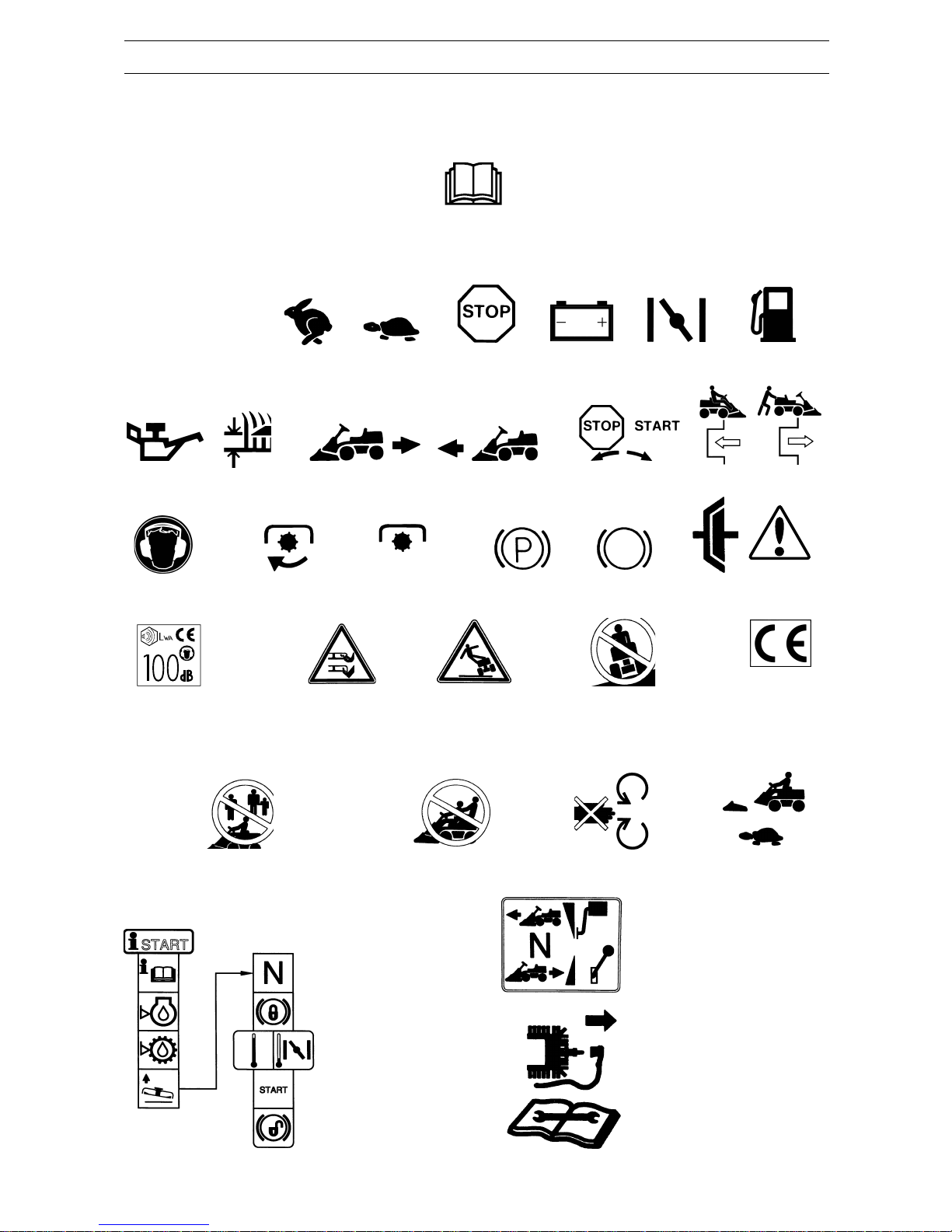
These symbols can be found on the Rider and in the operator’s manual.
Study them carefully so you understand their significance.
Read the operator’s manual.
Reverse Neutral Fast Slow Engine off Battery Choke Fuel
Oil level Cutting height Reversing Forward Ignition Hydrostatic free wheeling
EXPLANATION OF SYMBOLS
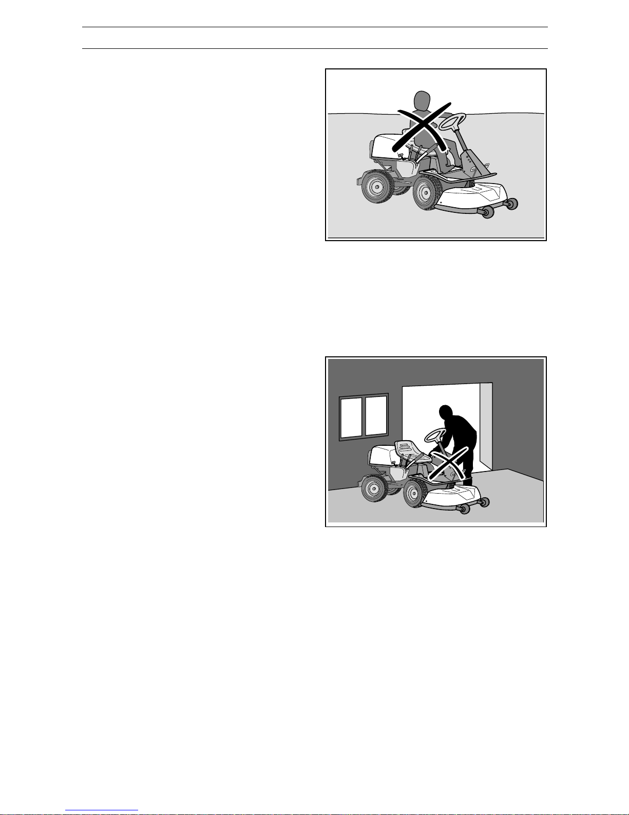
Never use the Rider if persons, especially
children or pets, are in the immediate vicinity
Never carry passengers on the Rider
or on its tools
Starting instruction
Read the operator’s manual
Check the engine oil level
Check the oil level in the hydrostat
Lift up the mowing deck
Put the gear shift lever/hydrostat
pedals in the neutral position
Brake
Use the choke if the engine is cold
Starting the engine
Disengage the parking brake
before driving
Drive very slowly
without the mowing
deck
Do not insert your hands or
feet under the cover when
the engine is running
Accelerator pedal forward
Neutral position
Accelerator pedal reversing
Switch off the engine and remove
the ignition cable before carrying
out repairs or maintenance
CE conformity
marking
Warning!
Rotating blades
Warning! Risk of
the Rider overturning
Never drive directly across
a slope
Noise emissions to surroundings
in accordance with the European
Union’s directive. The machine’s
emissions are set out in the
chapter TECHNICAL DATA and
on the decal.
Use hearing protection Clutch in Clutch out Parking brake Brake Clutch Warning
Page 7
English – 5
8010-047
6003-002
8010-052
Safety instructions
These instructions are for your safety. Read them carefully.
General use
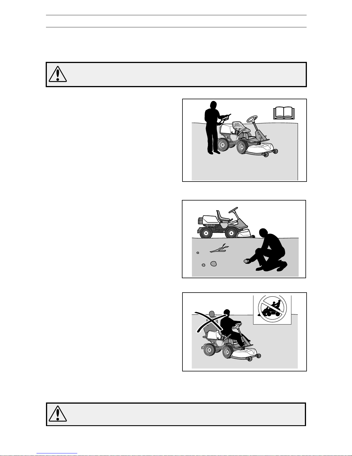
• Read all the instructions in this operator’s
manual and on the machine before you start it.
Ensure you understand them and then observe
them.
• Learn how to use the machine and its controls
safely and learn to how to stop quickly. Also
learn to recognize the safety decals.
• Only allow the machine to be used by adults
who are familiar with its use.
• Make sure nobody else is in the vicinity of the
machine when you start the engine, engage the
drive or drive off.
• Make sure animals and people maintain a safe
distance from the machine.
• Stop the machine if any one enters the working
area.
• Clear the area of objects such as stones, toys,
wires, etc. that may become caught in the
blades and be thrown out.
• Look out for the ejector and do not direct it
towards anyone.
• Stop the engine and prevent the engine from
being started until you have cleaned the cutting
unit or outlet channel.
• Remember the operator is responsible for
danger or accidents.
• Never carry passengers. The machine is only
intended to be used by one person.
• Always look downwards and backwards before
and while reversing. Keep watch for both large
and small obstacles.
• Slow before cornering.
• Switch off the blades when you are not mowing.
SAFETY INSTRUCTIONS
WARNING!
This machine can sever hands and feet as well as throw objects.
Failure to observe the safety instructions can result in serious injuries.
WARNING!
The inserted symbol means that important safety instructions need to be observed. It
applies to your safety.
Never carry passengers.
Read the operator’s manual before starting the machine.
Clear the area of objects before mowing.
Page 8
6– English
6003-006
8011-292
• Take care when rounding a fixed object, so that
the blades do not hit it. Never run the machine
over foreign objects.
• Only use the machine in daylight or in other
well-lit conditions. Keep the machine at a safe
distance from holes or other irregularities in the
ground. Pay attention to other possible risks.
• Never use the machine if you are tired, if you
have consumed alcohol, or if you are taking
other drugs or medication that can affect your
vision, judgment or co-ordination.
• Keep an eye on the traffic when working close
to a road or when crossing it.
• Never leave the machine unsupervised with the
engine running. Always stop the blades, apply
the parking brake, stop the engine and remove
the keys before leaving the machine.
• Never allow children or other persons not
trained in the use of the machine to use or
service it. Local laws may regulate the age of
the user.
SAFETY INSTRUCTIONS
WARNING!
Engine exhaust, some of its
constituents and certain vehicle
components contain or emit
chemicals considered to cause
cancer, birth defects or other
reproductive impairment. The
engine emits carbon monoxide,
which is a colourless, poisonous
gas. Do not use the machine in
enclosed spaces.
WARNING!
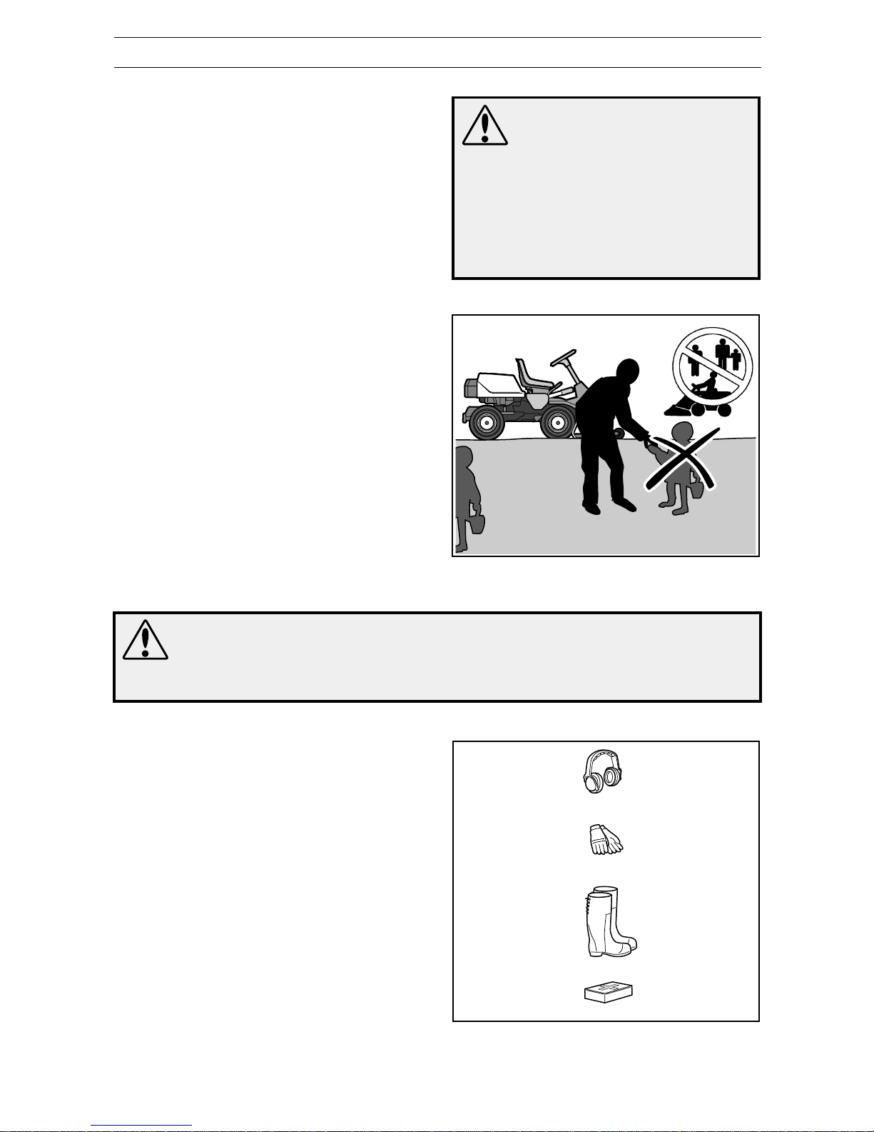
You must use approved personal protective equipment whenever you use the machine. Personal protective equipment cannot eliminate the risk of injury but it will
reduce the degree of injury if an accident does happen. Ask your dealer for help in
choosing the right equipment.
• Make sure that you have first aid equipment
close at hand when using the machine.
• Never use the machine when barefoot. Always
wear protective shoes or protective boots,
preferably with steel toes.
• Wear approved protective glasses or full-face
visor during assembly and when operating.
• Never wear loose fitting clothes that can catch in
moving parts.
• Use ear protectors to eliminate the risk for
impairment of hearing.
Keep children away from the area to be mowed.
Personal protective equipment.
Page 9
English – 7
8010-054
6003-004
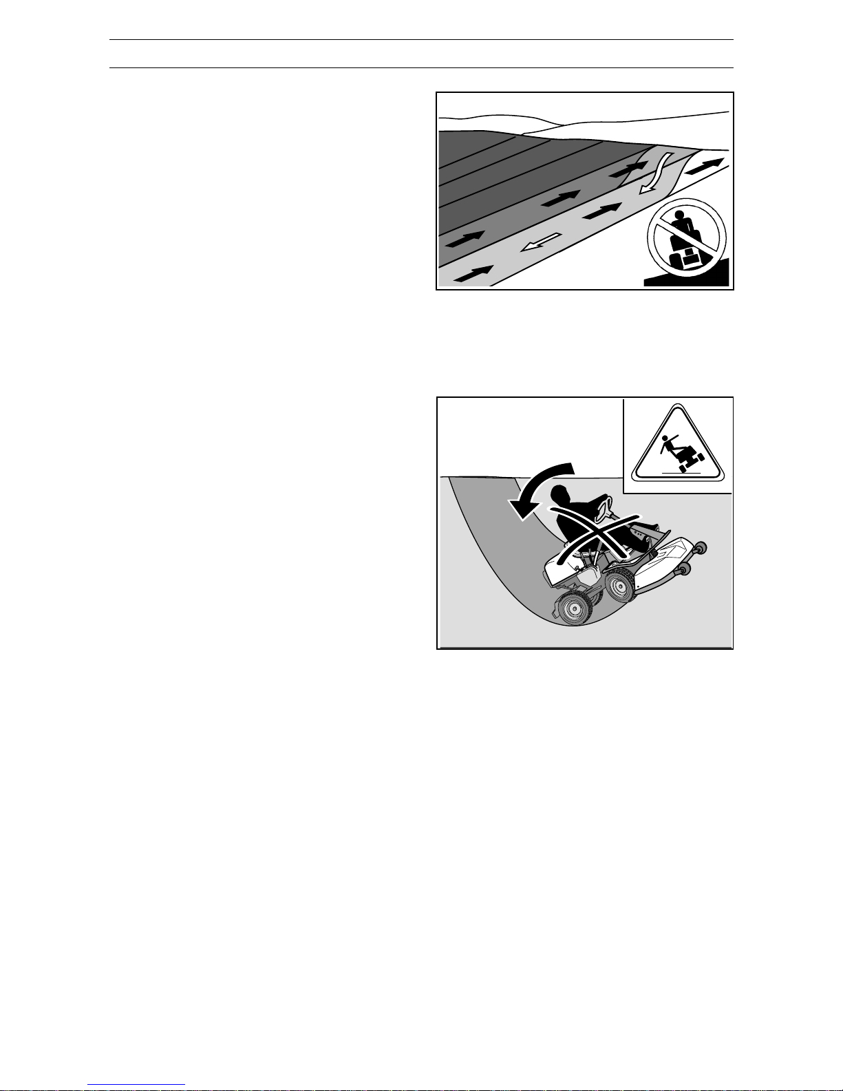
Be especially careful when driving on slopes.
Mow upwards and downwards on slopes, not sideways.
Driving on slopes
Driving on slopes is one of the operations where
the risk of the driver losing control of the machine or
of it overturning is the greatest; this can result in
serious injury or death. All slopes demand extra
care. If you cannot reverse up a slope or if you feel
unsure, do not mow it.
Proceed as follows:
• Remove obstacles such as stones, branches,
etc.
• Mow upwards and downwards, not sideways.
• Do not use the machine on ground that slopes
more than 15°.
• Avoid starting or stopping on a slope. If the tyres
start to slip, stop the blades and drive slowly
down the slope.
• Always drive smoothly and slowly on slopes.
• Do not make any sudden changes in speed or
direction.
• Avoid unnecessary turns on slopes, if
necessary, turn slowly and gradually downwards
if possible.
• Watch out for and avoid driving over furrows,
holes and bumps. It is easier for the machine to
overturn on uneven ground. Tall grass can hide
obstacles.
• Drive slowly. Use small movements of the
steering wheel. Select a low gear, so you do not
need to stop to change gear. Engine braking on
the machine is also better in a low gear.
• Take extra care if any attachments are fitted that
can change the stability of the machine.
• Do not mow too close to edges, ditches or
banks. The machine can suddenly overturn if
one wheel comes over the edge of a steep slope
or a ditch, or if an edge gives way.
• Do not mow wet grass. It is slippery, and tyres
can lose their grip so that the machine skids.
• Do not try to stabilize the machine by putting
your foot on the ground.
• When cleaning the chassis the machine must
never be driven close to an edge or ditch.
• Follow the manufacturer’s recommendations
regarding wheel weights or counterbalance
weights to increase stability.
SAFETY INSTRUCTIONS
Page 10
8– English
8010-057
8010-058
Children
• Serious accidents may occur if you fail to be on
your guard for children in the vicinity of the
machine. Children are often attracted to the
machine and mowing. Never assume that
children will remain where you last saw them.
• Keep children away from the area to be mowed
and under close supervision by another adult.
• Keep an eye out and shut off the machine if
children enter the work area.
• Before and during reversing procedures, look
behind you and down for small children.
• Never allow children to ride along. They can fall
off and seriously injure themselves or be in the
way for safe manoeuvring of the machine.
• Never allow children to operate the machine.
• Be particularly careful near corners, bushes,
trees or other objects that block your view.
SAFETY INSTRUCTIONS
Never allow children to operate the machine.
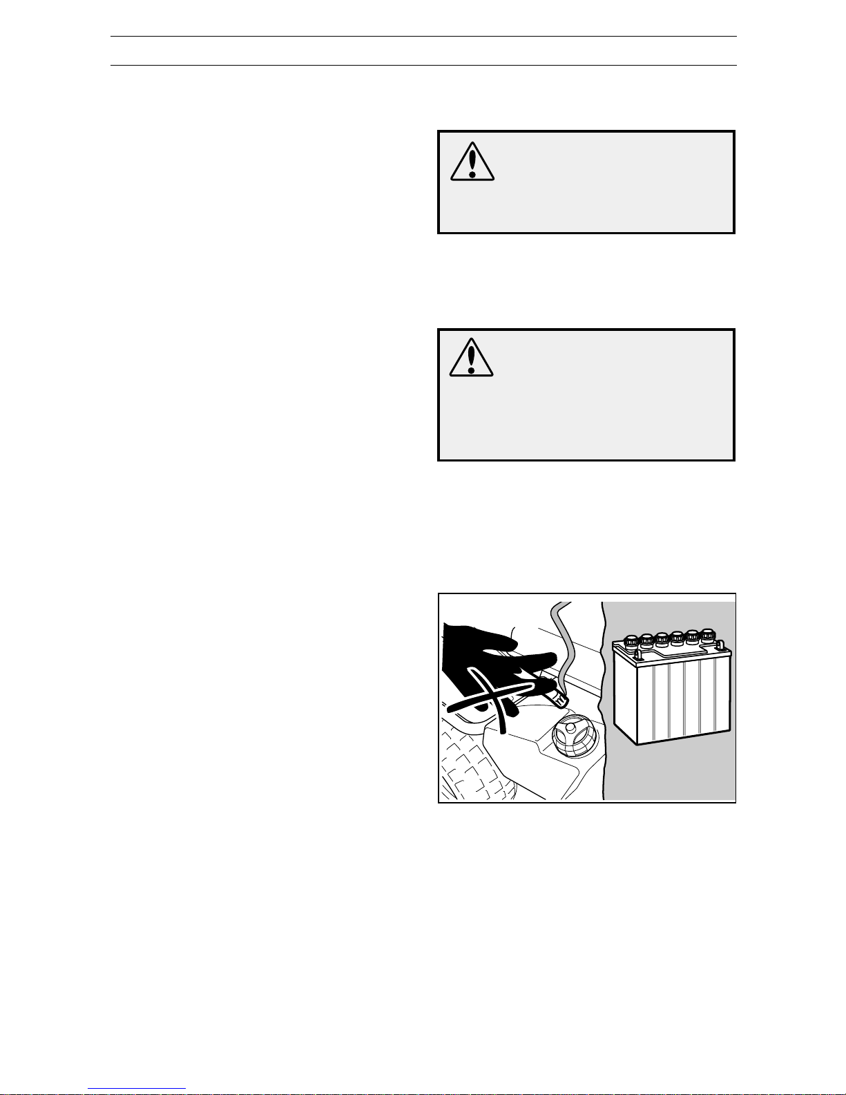
Never fill the fuel tank indoors.
Maintenance
• Stop the engine. Prevent starting by removing
the ignition cable from the spark plug or remove
the ignition key before making any adjustments
or carrying out maintenance.
• Never fill the fuel tank indoors.
• Petrol and petrol fumes are poisonous and
extremely flammable. Be especially careful
when handling petrol, as carelessness can
result in personal injury or fire.
• Only store fuel in containers approved for the
purpose.
• Never remove the fuel cap and fill the petrol
tank while the engine is running.
• Allow the engine to cool before refuelling. Do
not smoke. Do not fill petrol in the vicinity of
sparks or naked flames.
• Observe the risk of environmental damage
when handling oil, fuel and the battery. Remember to follow local regulations concerning waste
handling.
• Electric shocks can result in injury. Do not touch
the ignition lead when the engine is running. Do
not test the ignition system with your fingers.
Page 11
English – 9
WARNING!
The engine, and components of
the exhaust and hydraulic
systems become extremely hot
during operation. Risk for burns
with contact.
WARNING!
The battery contains lead and
lead pollutants, chemicals that
are considered to cause cancer,
birth defects or other reproductive impairment. Wash your
hands after touching the
battery.
8009-242
• If leaks arise in the fuel system, the engine must
not be started until the problem has been
resolved.
• Store the machine and fuel in such a way that
there is no risk that leaking fuel or fumes can
cause any damage.
• Check the fuel level before each use and leave
space for the fuel to expand, because the heat
from the engine and the sun may otherwise
cause the fuel to expand and overflow.
• Avoid overfilling. If you spill petrol on the
machine, wipe up the spill and wait until it has
evaporated before starting the engine. If you
spill petrol on your clothing, change your
clothing.
• Allow the machine to cool before performing any
actions in the engine compartment.
• Be especially careful when handling battery
acid. Acid on the skin can cause serious
corrosive injuries. In the event of spillage on the
skin wash immediately with water.
• Acid in the eyes can cause blindness, contact a
doctor immediately.
• Take care with battery maintenance. Explosive
gases form in the battery. Never perform
maintenance on the battery while smoking or in
the vicinity of open flames or sparks. This can
cause the battery to explode and cause serious
injuries.
• Make sure all nuts and bolts are tightened
correctly and that the equipment is in good
condition.
• Do not modify safety equipment. Check
regularly to be sure it works properly. The
machine must not be driven if protective plates,
protective covers, safety switches or other
protective devices are not fitted or are defective.
• Do not change the setting of governors and
avoid running the engine at excessively high
revs. If you run too fast, you risk damaging the
machine components.
• Observe the risk of injury caused by moving or
hot parts if the engine is started with the engine
cover opened or the protective covers removed.
SAFETY INSTRUCTIONS
Do not smoke when carrying out maintenance.
Page 12
10– English
8009-467
8010-061
SAFETY INSTRUCTIONS
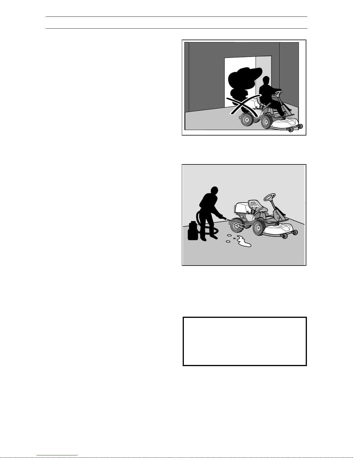
• Never use the machine indoors or in spaces
lacking proper ventilation. Exhaust fumes
contain carbon monoxide, an odourless,
poisonous and highly dangerous gas.
• Stop and inspect the equipment if you run over
or into anything. If necessary, make repairs
before starting.
• Never make adjustments with the engine
running.
• The machine is tested and approved only with
the equipment originally provided or
recommended by the manufacturer.
• The blades are sharp and can cause cuts. Wrap
the blades or wear protective gloves when
handling them.
• Check regularly that the parking brake works.
Adjust and maintain as required.
• The mulching unit should only be used where
better quality mowing is required and in known
areas.
• Reduce the risk of fire by removing grass,
leaves and other debris that may have fastened
on the machine. Allow the machine to cool
before putting it in storage.
Transport
• The machine is heavy and can cause serious
crush injuries. Be especially careful when it is
loaded in or out of a car or on and off of a trailer.
• Use an approved trailer to transport the machine. Activate the parking brake and secure the
machine using approved fasteners, such as
tension belts, chains or ropes when transporting.
• Check and observe local road traffic regulations
before transporting or driving the machine on
roads.
IMPORTANT INFORMATION
The parking brake is not sufficient to lock the
machine during transport. Ensure you secure
the machine firmly to the transporting vehicle.
Reverse the machine on to the transporting
vehicle to prevent it from overturning.
Regularly clean grass, leaves and other debris from the
machine.
Never run the machine in an enclosed area.
Page 13
English – 11
8009-244
8009-245
8009-243
78 9 10 11 12
65 4 3 2113
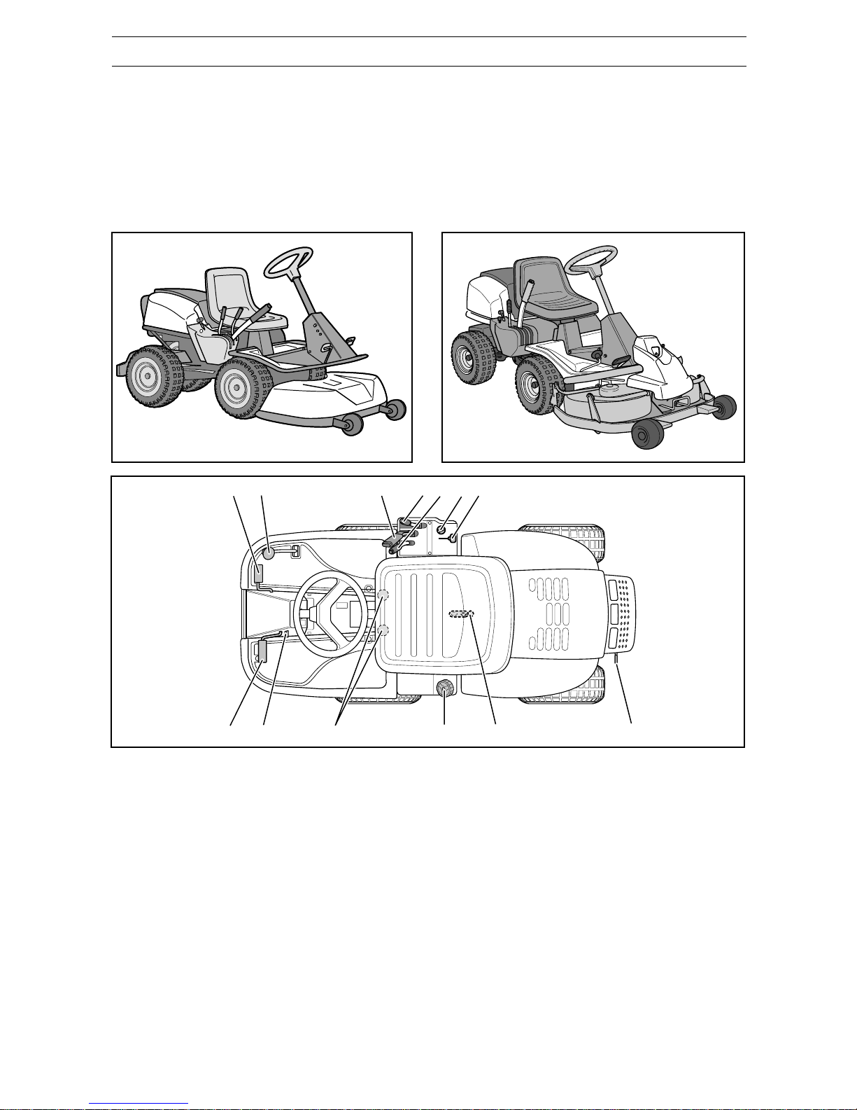
PRESENTATION
Presentation
Congratulations on your choice of an exceptionally
high quality product.
Four models equipped with engines from Briggs &
Stratton are described in this operator’s manual.
FR 2111 has an inline type gearbox with 5 forward
gears and reverse.
On FR 2113 and FR 2116 transmission is by means
of a variable speed hydrostatic gearbox.
FR 2113 is available in two versions. FR 2113 A has
a mowing deck with rear ejection and FR 2113 MA
has a mowing deck with mulching.
Placement of controls
1. Ignition key
2. Throttle/Choke control
3. Adjustment of the cutting height
4. Lifting lever, mowing deck
5. Accelerator for reversing, FR 2113,
FR 2116
6. Accelerator for driving forwards, FR 2113,
FR 2116
Parking brake, FR 2111
7. Parking brake, FR 2113, FR 2116
Clutch pedal, FR 2111
8. Lock button for the parking brake
left-hand side for FR 2113, FR 2116
right-hand side for FR 2111
9. Seat adjustment
10. Fuel cap
11. Main lock (under seat)
12. Lever for disengaging the drive, FR 2113,
FR 2116.
13. Gear shift lever, FR 2111
Page 14
12– English
8009-246
6004-005
6004-006
PRESENTATION FR 2111
Throttle and Choke controls
The throttle is used to control the speed of the
engine and thereby also the rotation speed of the
blades.
The control is also used to activate the choke.
When the choke is engaged a richer fuel/air mixture
is fed to the engine, which facilitates starting in the
cold.
Clutch pedal
The clutch pedal disengages the engine and stops
propulsion.
The blade drive is
not
affected by the clutch pedal.
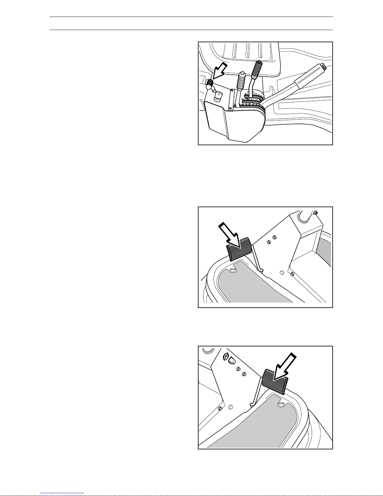
Brake pedal / Parking brake
The brake pedal activates a disc brake that is
located on the gearbox and stops the drive gear.
The clutch pedal should also be pressed down
when braking to achieve the best braking effect.
The brake pedal also acts as a parking brake if the
lock button is pressed in when the pedal is pressed
down.
Page 15
English – 13
8009-247
8009-248
6004-006H
PRESENTATION FR 2113, FR 2116
Parking brake
The parking brake is activated as follows:
1. Press down the brake pedal.
2. Press in the lock button on the steering column.
3. Release the brake pedal while holding in
the button.
The parking brake lock is automatically disengaged
when the brake pedal is pressed down.
Throttle and Choke controls
The throttle is used to control the speed of the
engine and thereby also the rotation speed of the
blades.
The control is also used to activate the choke.
When the choke is engaged a richer fuel/air mixture
is fed to the engine, which facilitates starting in the
cold.
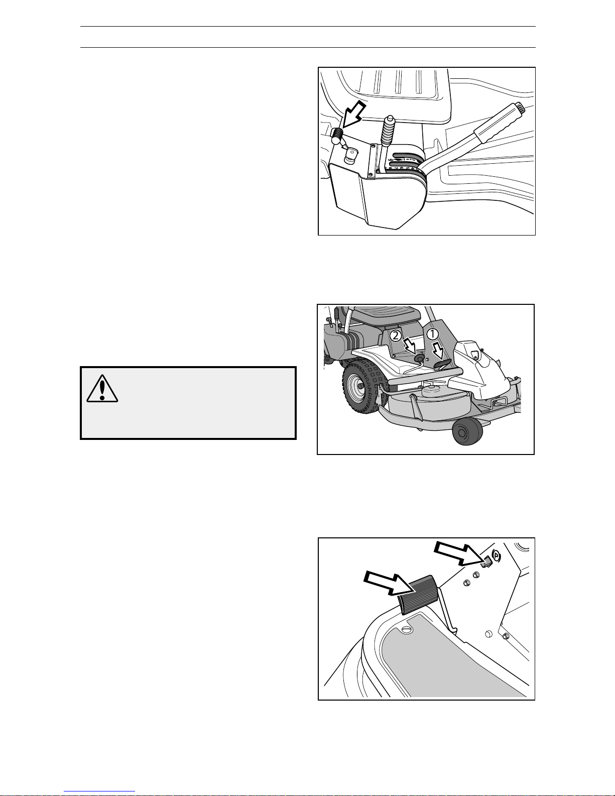
Accelerator
The speed of the machine is variably controlled
using two pedals. Pedal (1) is used to travel forwards and pedal (2) to reverse.
WARNING!
Make sure that no branches can
interfere with the pedals when
mowing under bushes.
Risk for unintentional
manoeuvring.
Page 16
14– English
8009-249
8009-250
8009-261
8009-260
PRESENTATION
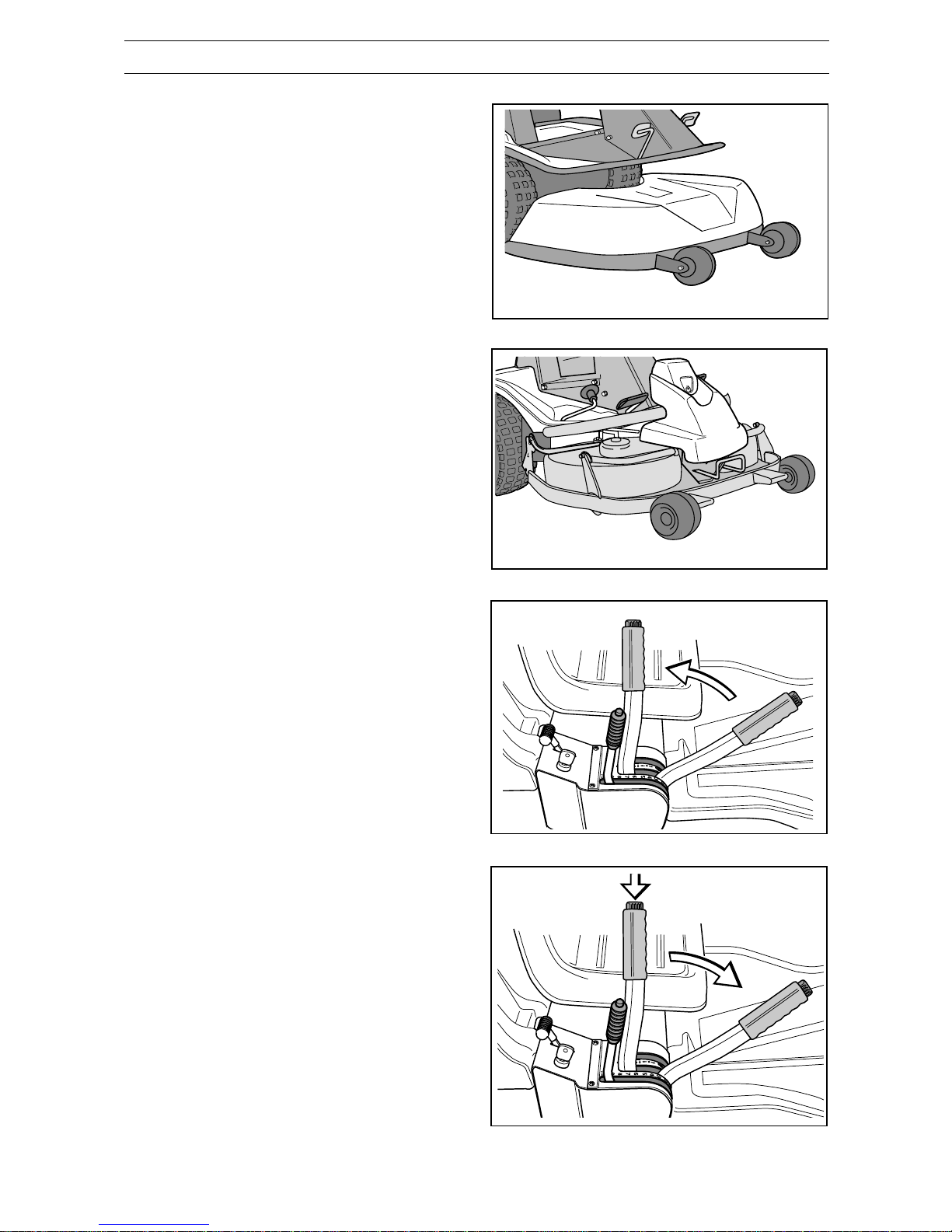
Lifting lever for the mowing deck
The lifting lever is used to put the mowing deck in
either the transport or mowing positions.
If the lever is pulled backwards the deck is raised
and the blades automatically stop rotating (transport position).
If the lock button is pressed in and the lever is
moved forwards the deck will be lowered and the
blades will automatically start to rotate (mowing
position).
The lever can also be used to temporarily adjust the
cutting height, for example, with a small mound in
the lawn.
Mowing deck
FR 2111 and FR 2113 A have a triple blade mowing
deck with rear ejection, i.e. the clippings are thrown
out behind the mowing deck.
FR 2113 MA has a double blade mulching unit and
FR 2116 MA has a triple blade Combi unit, which
can be set to either a mulching function or rear
ejection by removing a mulching plug.
Lifting the mowing deck (transport position)
Lowering the mowing deck (mowing position)
Page 17
English – 15
8009-251
6004-014
8009-252
PRESENTATION
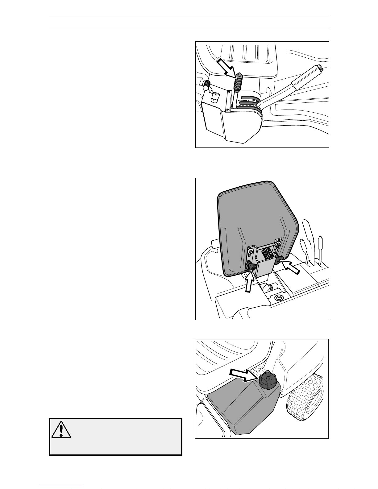
Lever to adjust the cutting height
Using the lever the cutting height can be adjusted in
9 different positions.
Deck with rear ejection, 40-90 mm
(1 9/16" - 3 9/16")
Mulching and combi unit, 45-95 mm
(1 3/4" - 3 3/4")
Seat
The seat has a hinged mounting on the front edge
and can be folded forwards.
The seat can also be adjusted lengthways.
Loosen the handles under the seat and adjust it
forwards or backwards to the desired position.
Secure the adjustment using the handles.
WARNING!
Petrol is highly flammable.
Observe caution and fill the tank
outdoors
(see the safety instructions).
Refuelling
The engine should be run on a minimum of
85-octane grade unleaded petrol (not mixed with
oil). It can be beneficial to use environmentally
adapted alkylate petrol.
Do not use petrol that contains methanol.
Do not fill the tank completely, leave an expansion
area of at least 2.5 cm (1").
Page 18

16– English
DRIVING
3. On FR 2111
Put the gear shift lever in the N position
(neutral).
Starting the engine
1. Lift up the mowing deck by pulling the lever
backwards to the locked position (transport
position).
2. Activate the parking brake. This is done as
follows:
• Press down the brake pedal (1).
• Press in the lock button on the steering
column (2).
• Release the brake pedal while keeping the
button pressed in.
The parking brake’s lock is automatically
disengaged when the brake pedal is pressed
down.
The FR 2111 has the brake pedal and lock
button on the right-hand side.
Before starting
• Read the safety instructions and information
concerning the placement of controls and
functions before starting.
• Carry out daily maintenance before starting
(see the maintenance schedule).
Adjust the seat to the desired position.
IMPORTANT INFORMATION
Do not press down the reversing lock button
on the lever when engaging the neutral
position. Otherwise this will activate the start
lock function.
1
2
N
8009-249
6007-002H
8009-253
8009-430
IMPORTANT INFORMATION
The air intake grille in the engine cover
behind the driver’s seat must not be
blocked by, for example, clothing, leaves,
grass or dirt.
Impaired cooling of the engine. Risk of
major engine damage.
Page 19

English – 17
STOP
START
1
2
3
1
2
3
8009-254
8009-255
8009-256
IMPORTANT INFORMATION
Do not run the starter motor for more than
15 seconds at a time. If the engine does
not start wait about 1 minute before trying
again.
DRIVING
With a cold engine:
4. Move the throttle to position 3 (choke position).
In this position the engine is fed with a richer
mixture, which means the engine is easier to
start.
The throttle must be moved to the side (towards
the ignition key) to reach the choke position.
6. Turn the ignition key to the start position.
With a warm engine:
5. Move the throttle in between positions 1 and 2.
Page 20

18– English
N
STOP
START
8009-257
6007-010H
8009-248
8009-253
DRIVING
WARNING!
Never run the engine indoors, in
enclosed or badly ventilated
areas. Engine exhaust fumes
contain poisonous
carbon monoxide.
7. Once the engine has started release the ignition
key back to the neutral position.
Move the throttle to the required engine speed.
When mowing 3/4 to full throttle.
IMPORTANT INFORMATION
Gear changes between forward gears must
not be made while the machine is moving.
The engine must be disengaged during each
gear change.
Stop the machine before changing between
forward and reverse gears, otherwise this
may result in damage to the gearbox.
Never use force to engage a gear. If a gear
does not engage immediately, release the
clutch pedal and press it down again. Now try
to engage the gear again.
Driving the Rider
1. Release the parking brake by pressing down the
brake pedal.
2. On FR 2113, FR 2116
Carefully press down one of the pedals until the
required speed is obtained.
Pedal (1) is pressed down to travel forwards and
pedal (2) to reverse.
On FR 2111
Disengage the engine and select the required
gear.
The lock button must be held in to engage
reverse gear.
• Gears 1-4 are used for mowing
• Gears 4-5 are used for transporting
Starting can take place independent of which
gear is selected.
Page 21

English – 19
8009-251
8009-250
Mowing pattern
WARNING!
Clean all stones and other objects
that can be thrown
by the blades from the lawn.
DRIVING
3. Select the required cutting height (1-9) using the
cutting height lever.
In order to obtain an equal cutting height, it is
important that the air pressure is the same in
both front wheels (60 kPa/8.5 PSI).
Mowing tips
• Find and mark out any stones and other fixed
objects to avoid colliding with them.
• Start with a high cutting height and reduce it
until the desired mowing result is obtained.
• The best mowing result is achieved with high
engine revs (the blades rotate quickly) and low
speed (the Rider moves slowly). If the grass is
not too long and thick the driving speed can be
increased without significantly impairing the
mowing result.
4. Press in the lock button on the lifting lever and
lower the mowing deck.
IMPORTANT INFORMATION
The life span of the drive belts is in-
creased significantly if the engine runs at
a low speed when the blades are engaged.
Therefore only accelerate once the mowing deck has been lowered into the mowing position.
• The finest lawns are obtained if they are mown
frequently. Mowing will be more even and the
clippings will be more evenly distributed across
the area. The overall mowing time will not be
longer as higher driving speeds can be selected
without impairing the mowing result.
• Avoid mowing wet lawns. The mowing result will
be poorer as the wheels will sink into the soft
lawn.
• Rinse off the underside of the mowing deck after
use with water, do not use a high pressure
washer. Now put the mowing deck in the service
position.
• It is extremely important when the Mulching unit
is used that the intervals between mowing are
not too long.
Page 22

20– English
STOP
START
MAX 15°
6007-013
8009-249
8009-258
8009-259
DRIVING
WARNING!
Do not use the Rider on ground
that slopes more than 15°. Mow
upwards and downwards on
slopes, never sideways. Avoid
sudden changes in direction.
Clutch control FR 2113, FR2116
The clutch control must be pulled out in order for
the Rider to be moved when the engine is shutoff.
Starting on slopes, manual gearbox
1. Press down the parking brake
2. Move the throttle to full throttle.
3. Disengage the engine and select 1st gear.
4. Gradually release the clutch pedal.
5. When the engine starts to pull, release the
parking brake.
Stopping the engine
Preferably let the engine idle for a minute so it runs
at its normal working temperature before it is
stopped if it has worked hard.
1. Lift up the mowing deck by pulling the lever
backwards to its end position.
2. FR 2111: Pull back the throttle and move the
gear shift lever to the neutral position N, without
pressing in the reversing lock button.
Turn the ignition key to the STOP position.
FR 2113, FR 2116: Pull back the throttle and
turn the ignition key to the STOP position.
3. When the Rider is at a standstill, hold down the
parking brake and press in the reversing lock
button.
Page 23

English – 21
Maintenance schedule
The following is a list of maintenance procedures that must be performed on the Rider. For those points not
described in this manual, visit an authorised service workshop.
● = Described in this operator’s manual.
❍ = Not described in this operator’s manual.
WARNING!
No service operations may be performed on the engine or mowing deck unless:
• The engine has been stopped. • The parking brake is actuated.
• The ignition key has been removed. • The mowing deck is disengaged.
• The ignition cable has been removed from the spark plug.
MAINTENANCE
1)
First change after 5 hours. Replace after every 25 hours with heavy loads or high temperatures.
2)
Under dusty conditions cleaning and replacement should take place more frequently.
3)
With daily use, the Rider should be lubricated twice weekly.
4)
Performed by an authorised service workshop.
Check the engine oil level 39 ●
Check the engine’s cooling air intake 31 ●
Check the fuel pump’s air filter 28 ●
Check the steering wires 24 ●
Check the brakes 25 ●
Check the battery 28 ●
Check the safety system 29 ●
Check nuts and bolts – ❍
Check for any fuel or oil leakage – ❍
Clean around the silencer – ❍
Change the engine oil
1)
39 ●
1)
●
1)
Replace the air filter’s prefilter on FR 2116
2)
27 ●
Check the mowing deck 32 ●
Check the air pressure in the tyres (60 kPa/8.5 PSI) 31 ●
Lubricate the belt adjuster
3)
40 ●
Lubricate joints and shafts
3)
40 ●
Adjust the brakes FR 2111 25 ●
Check the V-belts – ❍
Check the transmission’s cooling fins on FR 2113, 2116 – ❍
Check the transmission’s oil level on FR 2113, 2116 40 ●
Adjust the brakes on FR 2113, 2116 25 ●
Inspecting and adjusting the throttle cable 26 ●
Clean the engine’s and transmission’s cooling fins
2,4)
– ❍
Replace the air filter’s prefilter and paper filter
2)
27 ●
Replace the fuel filter 26 ●
Replace the spark plug 28 ●
50
100
Page
Maintenance
interval hours
25
Maintenance
Daily
maintenance
before
starting
Page 24

22– English
8009-262
8009-263
8009-264
MAINTENANCE
Front cover FR 2113 MA, FR 2116 MA
Loosen the snap-in lock and lift off the cover.
Dismantling the Rider covers
Engine cover
The engine becomes accessible for service when
the engine cover is folded up.
Fold the seat forward, loosen the rubber strap
under seat and fold the cover backwards.
Front cover FR 2111, FR 2113 A
Remove the bolts holding the front cover (3) and lift
off the cover.
Page 25

English – 23
8009-265
8009-266
MAINTENANCE
Left-hand wing cover
Remove the bolts holding the wing cover and lift off
the cover.
Right-hand wing cover
Remove the bolts holding the wing cover (2 and 3).
On FR 2113 and FR 2116 the knob (1) should also
be removed.
Page 26

24– English
8009-267
6008-009
6008-010
MAINTENANCE
3. If necessary, the wires can be adjusted by
tightening the adjuster nuts on each side of the
steering collar. Do not tension the wires too
much, they should only be
tightened
against the
steering collar.
Support the wire so it does not twist.
If you only tension one side the steering wheel’s
centre position may change.
Check the wire tension as set out in point 2
after you have made the adjustment.
Checking and adjusting the steering
wires
The steering is governed by means of wires.
After a period of use these can become stretched,
which means the steering setting may have
changed.
The steering is checked and adjusted as follows:
1. Dismantle the frame plate by removing the bolts
(two on each side).
2. Check the tension of the steering wires by
squeezing them together by the arrows as
illustrated.
It should be possible to squeeze the wires so
that the distance between them is half the size,
without using too much force.
Page 27

English – 25
2
1
1
6008-239H
6008-012
6008-011
WARNING!
A badly adjusted brake can result
in impaired braking capacity.
Checking and adjusting the brake on
FR 2113 and FR 2116
Check that the brake is correctly adjusted by
placing the Rider on a slight downhill and activate
the brake.
If the Rider does not standstill the brake needs
adjusting.
The brake is adjusted as follows:
1. Loosen the locking nuts (1).
2. Tension the wire using the adjuster screw (2)
until the play on the wire disappears.
3. Tighten the locking nuts (1).
4. The brake should be checked again after the
adjustment has been made.
Checking the brake FR 2111
The brake is a disc brake and is located on the
gearbox.
Check that the brake is adjusted correctly by
measuring the distance between the brake lever
and front edge of the cut-out on the chassis.
The distance should be 0-1 mm (0-0.040") when
the brake is not actuated.
Adjusting the brakeFR 2111
1. Loosen the locking nuts (1).
2. Tension the wire using the adjuster screw (2) so
that the distance between the brake lever and
cut-out’s front edge on the chassis is 1 mm
(0.040").
3. Tighten the locking nuts (1) after adjustment.
MAINTENANCE
Page 28

26– English
MAINTENANCE
Replacing the fuel filter
Replace the new fuel filter mounted on the supply
line after every 100 hours (once per season) or
more frequently if it is clogged.
Replace the filter as follows:
1. Fold up the engine cover.
2. Move the hose clips away from the filter.
Use a pair of flat pliers.
3. Pull the filter away from the ends of the hose.
4. Press the filter into the ends of the hose. If
necessary, a soap solution can be applied to
the ends of the filter to simplify assembly.
5. Move the hose clips back towards the filter.
2. Pull the throttle cable’s casing as far as possible
to the right and check that the choke is fully
actuated.
3. Tighten the clamping screw.
Adjusting the throttle cable
The throttle cable may need to be adjusted, if the
engine does not respond as it should when
accelerating, if it produces black smoke or
maximum revs are not reached.
1. Loosen the clamping screw (by the arrow), and
slide the throttle to the choke position.
4. Pull back the throttle to the full throttle position
and check that the choke is no longer actuated.
8009-402
8009-403
8009-404
8009-405
Page 29

English – 27
Replacing the air filter
If the engine seems to lack power or goes irregularly the reason may be that the air filter is clogged.
It is therefore important to replace the air filter at
regular intervals (see ”Maintenance schedule” for
correct service interval).
1. Fold open the engine cover.
2. Pull up the handle on the air filter cover, unhook
and turn towards the engine.
3. Remove the air filter cover.
4. Lift out the air filter cartridge from the fan
housing.
Replace the paper filter if it is clogged with dirt.
MAINTENANCE
IMPORTANT INFORMATION
Do not use compressed air to clean the
paper filter.
Filters should not be oiled. They should be
assembled dry.
5. Carefully lift the precleaner out of the fan
housing. Carefully clean the fan housing so that
dirt does not fall down into the carburetor.
6. Insert a new precleaner and air filter cartridge
in the fan housing.
7. Align the tabs on the cover with the slits in the
housing and replace the air filter cover.
8. Pull the handle outwards. Secure the handle in
the air filter cover and close the cover by
pressing it inwards.
8009-406
8009-409
8009-408
8009-407
8009-410
Page 30

28– English
6008-013
MAINTENANCE
Checking the fuel pump’s air filter
Check regularly that the fuel pump’s air filter is not
clogged by dirt.
The filter can be cleaned using a brush, if necessary.
WARNING!
Actions with acid contact
External: Rinse thoroughly with water.
Internal: Drink large quantities of water or
milk. Contact a doctor as soon as
possible.
Eyes: Rinse thoroughly with water.
Contact a doctor as soon as
possible.
The battery emits explosive gases. Sparks,
flames and cigarettes must not be present in
the vicinity of the battery.
Checking the acid level in the battery
Check that the acid level in the battery lies between
the markings. When refilling
only
distilled water may
be used to fill the cells.
Ignition system
The engine is equipped with an electronic ignition
system. Only the spark plug requires maintenance.
For the recommended spark plug, see Technical
data.
IMPORTANT INFORMATION
Fitting the wrong spark plug type can damage
the engine.
1. Remove the ignition cable shoe and clean
around the spark plug.
2. Remove the spark plug with a 5/8" (16 mm)
or13/16" (21 mm) spark plug socket wrench.
3. Check the spark plug. Replace the spark plug if
the electrodes are burned or if the insulation is
cracked or damaged. Clean the spark plug with
a wire brush if it is to be reused.
4. Measure the electrode gap with a gapping tool.
The gap should be 0.75 mm (0.030"). Adjust as
necessary by bending the side electrode.
IMPORTANT INFORMATION
Inadequately tightened spark plugs can
cause overheating and damage the engine.
Tightening the spark plug too much can
damage the threads in the cylinder head.
5. Reinsert the spark plug, turning by hand to
avoid damaging the threads.
6. After the spark plug is seated, tighten it using a
spark plug wrench so that the washer is
compressed. A used spark plug should be
turned 1/8 of a turn from the seated position. A
new spark plug should be turned 1/4 a turn
from the seated position.
7. Replace the ignition cable shoe.
8009-411
IMPORTANT INFORMATION
Do not turn over the engine if the spark
plug or ignition cable has been removed.
Page 31

English – 29
Checking the safety system
The Rider is equipped with a safety system that
prevents starting or driving under the following
conditions.
The engine should only be possible to start when
the mowing deck is in its raised position and the
gear shift lever or hydrostat pedals are in the
neutral position.
The driver does not need to be seated in the
driver’s seat.
Make daily inspections to ensure that the safety
system works by attempting to start the engine
when one of the conditions is not met. Change the
conditions and try again.
Check that the engine stops if you temporarily
move out of the driver’s seat while the mowing deck
is lowered or the gear shift lever/hydrostat pedals
are not in the neutral position.
Starter
Ignition system
Works
Does not work
MAINTENANCE FR 2111
N
FR 2111
Page 32

30– English
FR 2113, FR 2116
Checking the safety system
The Rider is equipped with a safety system that
prevents starting or driving under the following
conditions.
The engine should only be possible to start when
the mowing deck is in its raised position and the
gear shift lever or hydrostat pedals are in the
neutral position.
The driver does not need to be seated in the
driver’s seat.
Make daily inspections to ensure that the safety
system works by attempting to start the engine
when one of the conditions is not met. Change the
conditions and try again.
Check that the engine stops if you temporarily
move out of the driver’s seat while the mowing deck
is lowered or the gear shift lever/hydrostat pedals
are not in the neutral position.
Starter
Ignition system
Works
Does not work
MAINTENANCE FR 2113, FR 2116
Page 33

English – 31
Checking the tyres’ air pressure
The tyres’ air pressure should be 60 kPa
(0.6 kp/cm2/8.5 PSI) on all wheels.
In order to improve the drive power the pressure in
the rear tyres can be reduced to 40 kPa
(0.4 kp/cm25.6 PSI).
The highest permitted pressure is 100 kPa
(1.0 kp/cm2/14 PSI).
IMPORTANT INFORMATION
Different air pressure in the front tyres will
result in the blades mowing the grass at
different heights.
MAINTENANCE
Checking the engine’s cooling air intake
FR 2111, FR 2113, FR 2116
Clean the air intake grille in the engine cover
behind the driver’s seat.
Fold up the engine cover.
Check that the engine cooling air intake is free of
leaves, grass and dirt.
Check the air duct, located on the inside of the
engine cover, ensure it is clean and does not rub
against the cooling air intake.
A clogged air duct or cooling air intake impairs the
cooling of the engine, which may result in engine
damage.
8009-262
8009-268
8009-412
8009-370
RIDER 850
Main fuse
The fuse is located in a loose holder under the
battery case cover, in front of the battery.
Type: Flat-blade mounting, 15 A.
Do not use any other type of fuse when replacing.
A blown fuse indicates that the mounting has burnt
off.
Pull the fuse out of the holder when replacing. The
fuse is used to pro ect the electrical system. If it
blows again shortly after replacing this is due to a
short circuit, which must be rectified before the
machine is used again.
WARNING!
The cooling air intake rotates
when the engine is running. Mind
your fingers.
Air intake grille
Cooling air intake
Page 34

32– English
8009-269
8009-270
8009-271
Checking and adjusting the mowing
deck’s ground pressure on
FR 2113 MA and FR 2116 MA
In order to achieve the best mowing result the
mowing deck should follow the ground without
touching it too heavily.
The pressure is adjusted using a screw on each
side of the Rider.
1. Check that the tyres’ air pressure is 60 kPa
(0.6 kp/cm2/8.5 PSI).
2. Place a pair of bathroom scales under the
mowing deck’s frame (on the front edge) so that
the mowing deck rests on the scales. If
necessary a block can be placed between the
frame and the scales so that the support wheels
do not support any weight.
Checking the parallelism of the mowing
deck
Check the mowing deck’s parallelism as follows:
1. Check that the tyres’ air pressure is 60 kPa
(0.6 kp/cm2/8.5 PSI).
2. Place the Rider on a flat surface.
3. Measure the distance between the ground and
the front and back edges of the deck cover.
The mowing deck should have a slight slant,
with the rear edge 2-4 mm (1/8") higher than the
front edge.
MAINTENANCE
3. Adjust the mowing deck’s ground pressure by
screwing the adjuster screws, which are located
behind the front wheels on both sides, in or out.
The ground pressure should be between 12 and
15 kg (26.5 - 33 lbs).
Page 35

English – 33
2
6008-026H
8009-138
MAINTENANCE FR 2111, FR 2113 MA
Adjusting the parallelism of the mowing
deck on FR 2111
1. Check that the tyres’ air pressure is 60 kPa
(0.6 kp/cm2/8.5 PSI).
2. Dismantle the front cover and the right-hand
wing cover as described on pages 22-23.
3. Vertical adjustment of the mowing deck is
carried out using the adjuster nuts at the rear of
the lifting stay.
4. Raise the mowing deck at the front edge by
shortening the lifting stay.
Lower the mowing deck at the front edge by
lengthening the lifting stay.
5. Tighten the nuts against each other after
adjustment.
6. The parallelism should be checked again after
the adjustment has been made.
7. Fit the right-hand wing cover and the front cover.
Adjusting the parallelism of the mowing
deck on FR 2113 MA
1. Check that the tyres’ air pressure is 60 kPa
(0.6 kp/cm2/8.5 PSI).
2. Remove the front cover and the right-hand wing
cover.
3. Loosen the nut (1) on the parallelism stay.
Remove the locking clip (2) and the parallelism
stay.
4. Turn the fork anticlockwise to raise the cover’s
rear edge, clockwise to lower the cover’s rear
edge.
5. Secure the parallelism stay using the locking clip
and tighten the nut after adjustment.
6. The parallelism should be checked again after
the adjustment has been made.
7. Fit the right-hand wing cover and the front cover.
Page 36

34– English
6017-155
Adjusting the parallelism of the mowing
deck on FR 2116 MA
1. Check that the tyres’ air pressure is 60 kPa
(0.6 kp/cm2/8.5 PSI).
2. Remove the front cover and the right-hand wing
cover.
3. Loosen the parallelism stay’s nuts.
4. Screw out (extend) the stay to raise the rear
edge of the cover. Screw in (shorten) the stay to
lower the rear edge of the cover.
5. Tighten the nuts after adjustment.
6. The parallelism should be checked again after
the adjustment has been made.
7. Fit the right-hand wing cover and the front cover.
MAINTENANCE FR 2116 MA
8009-289
Removing the mulching plug
You need to remove the mulching plug, which is
fitted under the cutting unit with three screws, to
change a combi unit from a mulching function to a
cutting unit with rear ejection.
1. Put the cutting unit in the service position, see
”Placing in the service position”.
2. Remove the three screws holding the mulching
plug, and remove the plug.
3. Tip: Fit three, full-threaded screws M8x15 mm
in the screw holes to protect the threads.
4. Return the unit to the normal position.
To fit the mulching plug, follow the instructions in
the reverse order.
Page 37

English – 35
P
1
6017-218
6017-219
6017-220
MAINTENANCE FR 2113 MA, FR 2116 MA
The mowing deck’s service position
In order to provide good accessibility for cleaning,
repair and servicing, the mowing deck can be set in
the service position. The service position means
that the mowing deck is raised and locked in the
vertical position.
Placing in the service position
1. Position the machine so it stands flat. Activate
the parking brake (1). Set the mowing deck to
the lowest cutting height and lower the mowing
deck.
3. Loosen the two support wheels, located under
the front cover.
2. Remove the front cover by loosening the split
pin. (Complete instructions for the service
position can be found on the inside of the front
cover).
Page 38

36– English
6017-221
8009-272
8009-122
6017-223
MAINTENANCE FR 2113 MA, FR 2116 MA
4. Fit the two support wheels on each side of the
mowing deck’s rear section.
5. Loosen the spring on the drive belt’s belt idler.
6. Put your foot on the front edge of the mowing
deck next to the wheel and lift the mowing
deck’s front edge to make it easier to loosen the
height adjustment stay.
WARNING!
Wear protective glasses when
dismantling the mowing deck.
The spring that tension the belt
can fly off and cause personal
injury.
7. Secure the stay in the holder.
Page 39

English – 37
2
1
6017-225
6017-226
6017-227
8009-438
MAINTENANCE FR 2113 MA, FR 2116 MA
8. Lift off the drive belt (1).
Now pull out the split pin (2).
9. Pull the frame forwards and refit the pin.
10. Grasp the mowing deck’s front edge, pull out
and lift up into the service position.
If the cylindrical bolt, which is now holding the
mowing deck is removed, the mowing deck can
be lifted off.
Releasing the service position
To release the service position, reverse the procedures set out in Placing in the service position.
Make sure that the mowing deck’s lug (3) enters the
loop correctly on the underside of the machine, see
diagram.
WARNING!
Exercise care so that your hands
are not crushed.
Page 40

38– English
6008-024
6017-023
8009-137a
Mowing deck (rear ejection)
Mulching 90 cm FR 2113 MA
8009-288
Combi 103 cm FR 2116 MA
MAINTENANCE
Inspecting the blades
It is important that the blades are undamaged and
well-ground to give the best mowing result.
Check that the blades’ mounting bolts are
tightened.
IMPORTANT INFORMATION
Replacement or sharpening of the blades
should be carried out by an authorised
service workshop.
IMPORTANT INFORMATION
The blades on the double blade Mulching unit
should always be set relative to each other as
illustrated, with a 90° angle between the
blades. Otherwise the blades can collide and
cause damage to the mowing deck.
The blades should be balanced after sharpening.
Damaged blades should be replaced when hitting
obstacles that result in a breakdown. Let the
servicing dealer judge whether the blade can be
repaired/ground or must be discarded.
Replacing the shear pin FR 2113 MA
The blades are fitted with a shear pin to protect the
Mulching unit and its drive when colliding with
obstacles. A domed, spring friction washer is fitted
to each blade bolt. The washer must always be
replaced with a new washer when replacing the
shear pin. Otherwise the shear pin can break
causing the blades to collide.
Only use original spare parts. A set containing a
blade, shear pin and friction washer can be
purchased from your dealer.
1. Put the cutting unit in the service position, see
”Service position for the cutting unit\Placing in
the service position”.
2. Remove the blade (2A) by removing the blade
bolt with washer and friction washer (2B).
3. Remove the remains of the broken shear pin (3).
4. Make sure the contact surfaces (4) on the blade
and the blade mounting are free from metal.
Clean if necessary.
5. Fit a new shear pin (5) in the blade mounting.
6. Fit the blade (6), make sure it is fitted as illus-
trated.
7. Fit a new friction washer (7) with the concave
face turned towards the blade.
8. Fit the blade bolt with washer (8). Tightening
torque 45-50 Nm (4.5-5 kpm/32-36 lbft)
Page 41

English – 39
LUBRICATION
Changing the oil
The oil should be changed for the first time after 5
hours of running time. Thereafter it should be
changed every 50 hours of running time.
With heavy loads or high temperatures replace the
oil after every 25 hours.
WARNING!
Engine oil can be very hot if it is
drained off directly after the engine
is stopped. Therefore allow the
engine to cool down first.
IMPORTANT INFORMATION
Used engine oil is hazardous to health and
environment and must in accordance with
the law not be poured out on the ground
or in the nature, and must be handed in to
a workshop or other designated station for
treatment. Avoid skin contact, wash with
soap and water in the event of spillage.
Check the engine’s oil level
Check the oil level in the engine when the Rider
stands horizontal with the engine switched off.
Fold open the engine cover.
Release the dip stick and pull out. Wipe off the oil
and insert again.
The dip stick must be fully screwed down.
Now release the dip stick again and pull out. Check
the oil level.
The oil level should lie between the markings on dip
stick. If the level approaches the ADD mark, top up
with oil to the FULL mark.
The oil is filled in the same hole for the dip stick.
Fill the oil slowly. Tighten the dipstick correctly
before starting the engine. Start and run the engine
at idling speed for approx. 30 seconds. Turn off the
engine. Wait 30 seconds and check oil level. If
necessary fill so that the oil comes up to the ”FULL”
mark on the dipstick.
First and foremost use synthetic engine oil class
SJ-CF 5W/30 or 10W/30 for all temperature ranges.
Mineral oil SAE30, class SF–CC can be used at
temperatures > +5°C (40°F).
Do not mix different types of oil.
1. Place a receptacle under the engine’s drain
plug, located on the left-hand side of the engine.
2. Remove the dip stick and drain plug.
3. Let the oil run out into the receptacle.
4. Fit the drain plug and tighten.
5. Fill up with oil to the FULL mark on the dip stick.
The oil is filled in the same hole for the dip stick.
See ”Checking the engine’s oil level” above for
filling instructions. The engine holds 1.4 litres
(1.5 USqt) of oil.
6. Run the engine warm and then check that there
is no leakage from the drain plug.
ADD
FULL
ADD
FULL
8009-413
6008-035
8009-414
Page 42

40– English
8009-273
6008-240H
6008-232
LUBRICATION
Checking the oil level in the transmission
on FR 2113, FR 2116
1. Remove the transmission cover. Loosen both
screws (one on each side) and lift off the
transmission cover.
2. Check that there is oil in the transmission’s oil
tank. Fill if necessary with engine oil
SAE 10W/30 (class SF-CC).
Lubricating the belt adjuster
The belt adjuster should be lubricated regularly
using good quality molybdenum disulphide grease*.
1 nipple from the right-hand side under the engine’s
lower belt pulley, until grease is forced out.
With daily use, lubrication should be carried out
twice weekly.
General lubrication
All joints and bearings are lubricated using
molybdenum disulphide grease during manufacture. Continue to lubricate using the same type
of grease *. Lubricate the steering and control wires
using engine oil.
Carry out this lubrication regularly; with daily use,
the machine should be lubricated twice weekly.
* Grease from well-known brand names (petrol
companies, etc.) usually maintains a good quality.
The most important property is that the grease
provides good protection against corrosion.
Page 43

English – 41
8009-274
Lubricating the front wheel bearings
The front cover and wing covers must be removed
on machines with rear ejection, so that the tubular
loop can be lifted to remove the wheel.
1. Remove the plastic cover that covers the centre
of the wheel.
2. Remove the circlip and washer on the front
wheel axle.
3. Lift off the wheel.
4. Lubricate the stub axle with molybdenum
disulphide grease*.
5. Fit the parts in the reverse order.
IMPORTANT INFORMATION
Check that the circlip enters the groove
correctly.
LUBRICATION
* Grease from well-known brand names (petrol
companies, etc.) usually maintains a good quality.
The most important property is that the grease
provides good protection against corrosion.
Page 44

42– English
Problem Cause
The engine will not start • No fuel in the fuel tank
• Faulty spark plug
• Fault spark plug connection
• Dirt in the carburettor or fuel line
Starter does not turn the engine • Discharged battery
• Bad contact between the cable and battery pole
• Lifting lever for the mowing deck in the wrong position
• Main fuse blown. The fuse is placed in front of
the battery, under the battery cover.
• Faulty ignition switch
• Gear shift/hydrostat pedals not in the neutral position
The engine runs erratically • Faulty spark plug
• Incorrect carburettor setting
• Clogged air filter
• Blocked fuel tank ventilation
• Incorrect ignition setting
• Dirt in carburettor or fuel pipe
• Choking or incorrectly adjusted throttle cable
The engine lacks power • Clogged air filter
• Faulty spark plug
• Dirt in the carburettor or fuel line
• Incorrect carburettor setting
• Choking or incorrectly adjusted throttle cable
Engine overheating • Engine overloaded
• Air intake or cooling fins clogged
• Damaged fan
• Too low or no oil in the engine
• Faulty pre-ignition
• Faulty spark plug
Battery does not charge • One or more cells are defective
• Bad contact between the battery poles and cables
The Rider vibrates • The blades are loose
• The engine is loose
• Imbalance on one or more blades, due to damage
or inferior balancing after grinding
Uneven mowing result • Blades dull
• Mowing deck set incorrectly
• Tall or wet grass
• Grass build up under the cover
• Different air pressure in the right and left-hand tyres
• Too high driving speed
• Drive belt slips
• The blade has a broken shear pin (Mulching)
TROUBLE SHOOTING CHART
Page 45

English – 43
8009-243
8009-244
To ready the Rider for storage, follow these steps:
1. Clean the Rider carefully, especially under the
mowing deck. Touch up damage to the paint to
prevent rust.
2. Inspect the Rider for worn or damaged parts and
tighten any nuts or bolts that may have become
loose.
3. Change the engine oil; dispose of properly.
4. Empty the fuel tank. Start the engine and let it
run so that even the petrol in the carburettor is
emptied.
5. Remove the spark plug and pour about a
tablespoon of engine oil in the cylinder. Turn
over the engine so that the oil is evenly
distributed and then refit the spark plug.
6. Lubricate all grease nipples, joints and shafts.
7. Remove the battery. Clean, charge and store in
a cool place.
8. Store the Rider in a clean, dry place and cover it
for extra protection.
Cover
There is a cover to protect your machine during
storage or transport. Contact your dealer for a
demonstration.
Service
When ordering spare parts, please specify the
purchase year, model, type, and serial number of
the Rider.
Always use genuine spare parts.
An annual check-up or trimming at an authorised
service workshop is a good way to ensure that your
Rider performs at its best the following season.
Winter storage
At the end of the mowing season the Rider should
be readied for storage, likewise if it will not be in
use for longer than 30 days. Fuel allowed to stand
for long periods of time (30 days or more) can leave
sticky residues that can clog the carburettor and
disrupt engine function.
Fuel stabilisers are an acceptable option as regards
avoiding sticky residues during storage. If alkylate
petrol is used, stabilisers are unnecessary because
this fuel is stable. However, you should avoid
switching between regular and alkylate petrol as
sensitive rubber components can harden. Add
stabiliser to the fuel in the tank or in the storage
container. Always use the mixing ratios specified by
the manufacturer of the stabiliser. Run the engine
for at least 10 minutes after adding the stabiliser so
that it reaches the carburettor. Do not empty the
fuel tank and the carburettor if you have added
stabiliser.
STORAGE
WARNING!
Never store an engine with fuel in
the tank indoors or in poorly
ventilated spaces where fuel
vapour can come in contact with
open flames, sparks or a pilot
light such as in a boiler, hot
water tank, clothing drier, etc.
Handle the fuel with caution. It is
very flammable and careless use
can cause serious damage to
person and property. Drain the
fuel into an approved container
outdoors and far away from open
flames. Never use petrol for
cleaning. Use a degreasing agent
and warm water instead.
Page 46

44– English
Dimensions FR 2111 FR 2113 A
Length with mowing deck 2040 mm/6.6 ft 2040 mm/6.6 ft
Width 880 mm/2.89 ft 880 mm/2.89 ft
Height 1070 mm/3.52 ft 1070 mm/3.52 ft
Weight with mowing deck 216 kg/475 lbs 219 kg/481 lbs
Distance between axles 860 mm/2.81 ft 850 mm/2.81 ft
Wheel track front: 720 mm/2.36 ft 715 mm/2.34 ft
rear: 620 mm/2.04 ft 630 mm/2.06 ft
Tyre dimensions 16 x 7.5 x 8 16 x 7.5 x 8
Air pressure, front and rear 60 kPa (0.6 kp/cm2/8.5 PSI) 60 kPa (0.6 kp/cm2/8.5 PSI)
Max permitted slope 15° 15°
Engine
Make Briggs & Stratton Briggs & Stratton
model 215907 model 282H070110E2
Power 7.7/10.5 kW/hp 9.2/12.5 kW/hp
Displacement 344 cm
3
344 cm
3
Fuel at least 85 octane unleaded at least 85-octane unleaded
Tank volume 7.2 litres/7.6 USqt 7.2 litres/7.6 USqt
Oil synthetic SAE 5W/30 or SAE 10W/30 SAE 5W/30 or SAE 10W/30
class SJ-CF class SJ-CF
Oil volume 1.4 litres/1.5 USqt 1.4 litres/1.5 USqt
Start Electric start Electric start
Noise emissions and mowing width
Measured sound power 100 dB(A) 100 dB(A)
Guaranteed sound power 100 dB(A) 100 dB(A)
Mowing width 850 mm/33.5" 850 mm/33.5"
Electrical system
Type 12 V, negative grounded 12 V, negative grounded
Battery 12 V, 24 Ah 12 V, 24 Ah
Main fuse Flat-pin mounting 15 A Flat-pin mounting 15 A
Spark plug Champion QC12YC Champion QC12YC
Electrode gap 0.75 mm/0.030" 0.75 mm/0.030"
Transmission
Make Peerless MST 205 Tuff Torq K46
Oil - SAE 10W/30, class SF-CC
Number of forward gears 5 Number of reverse gears 1 Forward speed 0-9 km/h 0-9 km/h
Reverse speed 0-6 km/h 0-6 km/h
TECHNICAL DATA
Page 47

English – 45
TECHNICAL DATA
Dimensions FR 2113 MA FR 2116 MA
Length without mowing deck 2010 mm/6.58 ft 2010 mm/6.58 ft
Length with mowing deck 2220 mm/7.29 ft 2220 mm/7.29 ft
Width without mowing deck 880 mm/2.89 ft 880 mm/2.89 ft
Width with mowing deck 1000 mm/3.29 ft
Height 1070 mm/3.52 ft 1060 mm/3.48 ft
Weight with mowing deck 226 kg/497 lbs 229 kg/504 lbs
Distance between axles 850 mm/2.79 ft 855 mm/2.8 ft
Wheel track front: 720 mm/2.36 ft 715 mm/2.34 ft
rear: 630 mm/2.06 ft 625 mm/2.05 ft
Tyre dimensions 16 x 7.5 x 8 16 x 7.5 x 8
Air pressure, front and rear 60 kPa (0.6 kp/cm2/8.5 PSI) 60 kPa (0.6 kp/cm2/8.5 PSI)
Max permitted slope 15° 15°
Engine
Make Briggs & Stratton Briggs & Stratton
model 282H070110E2 model 282H070110E1
Power 9.2/12.5 kW/hp 15.5 kW/hp
Displacement 344 cm
3
465 cm
3
Fuel at least 85 octane unleaded at least 85-octane unleaded
Tank volume 7.2 litres/7.6 USqt 7.2 litres/7.6 USqt
Oil synthetic SAE 5W/30 or SAE 10W/30 SAE 5W/30 or SAE 10W/30
class SJ-CF class SJ-CF
Oil volume 1.4 litres/1.5 USqt 1.4 litres/1.5 USqt
Start Electric start Electric start
Noise emissions and mowing width
Measured sound power 98 dB(A) 100 dB(A)
Guaranteed sound power 100 dB(A) 100 dB(A)
Mowing width 900 mm/35.5" 1030 mm/40.5"
Electrical system
Type 12 V, negative grounded 12 V, negative grounded
Battery 12 V, 24 Ah 12 V, 24 Ah
Main fuse Flat-pin mounting 15 A Flat-pin mounting 15 A
Spark plug Champion QC12YC Champion QC12YC
Electrode gap 0.75 mm/0.030" 0.75 mm/0.030"
Transmission
Make Tuff Torq K46 Tuff Torq K46
Oil SAE 10W/30, class SF-CC SAE 10W/30, class SF-CC
Number of forward gears - Number of reverse gears - Forward speed 0-9 km/h 0-9 km/h
Reverse speed 0-6 km/h 0-6 km/h
Page 48

46– English
TECHNICAL DATA
In order to introduce improvements the specification and design are subject to alteration without prior
notice.
Note that no legal demands whatsoever can be made with the support of the information in this operator’s
manual.
Only use original spare parts with repairs. The use of other parts invalidates the warranty.
When this product is spent and is no longer used it should be returned to the
dealer or other authority for recycling.
Mowing deck
Type Triple blade cover Double blade cover Triple blade cover
with rear ejection Mulching 900 mm Combi 1030 mm
Mowing width 850 mm/33.5" 900 mm/35.5" 1030 mm/40.5"
Cutting heights
9 positions 40-90 mm/1 9/16" - 3 9/16" 45-95 mm/1 3/4" - 3 3/4" 45-95 mm/1 3/4" - 3 3/4"
Blade diameter 304 mm/12" 480 mm/19" 390 mm/15 3/8"
Page 49

English – 47
EU-DECLARATION OF CONFORMITY
EU declaration of conformity (Only applies to Europe)
Husqvarna AB, SE-561 82 Huskvarna, Sweden, tel: +46-36-146500, declares under sole responsibility that the
Rider Jonsered FR 2111, FR 2113 A, FR 2113 MA, FR 2116 MA, from 2002’s serial numbers and onwards (the year
is clearly stated in plain text on the rating plate with subsequent serial number), complies with the requirements of the
COUNCIL’S DIRECTIVES:
- of June 22, 1998 ”relating to machinery” 98/37/EC, annex IIA.
- of May 3, 1989 ”relating to electromagnetic compatibility” 89/336/EEC, and applicable supplements.
- of May 8, 2000 ”relating to the emission of noise to surroundings” 2000/14/EC.
Information regarding noise emissions and the mowing width, see the Technical Data.
The following harmonised standards have been applied: EN292-2, EN836.
The registered body 0404, SMP Svensk Maskinprovning AB, Fyristorgsgatan 3, SE-754 50 Uppsala, Sweden has
issued the report with number 01/901/001, 01/901/002, 01/901/003, 01/901/004 regarding the assessment of
conformity according to annex VI to the COUNCIL’S DIRECTIVE of May 8, 2000 ”relating to the emission of noise to
surroundings” 2000/14/EC.
Huskvarna January 3, 2002
Roger Andersson, Development Manager/Garden Products
Page 50

48– English
Delivery service
1. Fill the battery with battery acid and charge for four hours.
2. Fit the steering wheel, towing eye and where applicable other
components.
3. Adjust the mowing deck:
Adjust the lifting springs (the weight of the mowing deck should
be 12-15 kg/26.5-33 lbs). Only applies to the Mulching unit.
Adjust the mowing deck so its rear edge is about 2-4 mm (1/8")
higher than its front edge.
Adjust the mowing deck’s cutting height setting so that the
cutting height limit is 5 mm (3/16") above the deck frame at the
lowest cutting height.
4. Check that the right amount of oil is in the engine.
5. Check that the right amount of oil is in the transmission
(not FR 2111).
6. Check and adjust the air pressure in the tyres (60 kPa/0.6 bar/8.5 PSI).
7. Connect the battery.
8. Fill the fuel tank and start the engine.
9. Check that the machine does not move in neutral (not FR 2111).
10. Check:
Driving forwards.
Reversing.
Actuating the blades.
Safety switch for the seat.
Safety switch for the lifting lever.
Safety switch for the hydrostat pedals/neutral position.
11. Check that engine revs max. 2950 rpm.
12. Inform the customer about:
The need and benefit of following the service schedule.
The need and benefit of leaving the machine for
regular service.
The effects of maintenance on the machine’s second hand
value.
Application areas for Mulching.
13. Fill in the sales certificate, etc.
Delivery service has been
carried out.
No remaining notes.
Certified:
After the first 5 hours
1. Change engine oil.
Action
Date, stamp, signature
SERVICE SCHEDULE
Date, stamp, signature
Page 51

English – 49
○○○○○○○○○○○○○○○○○○○○○○○○○○○○○○○○○○○○○○○○○○○○○○○○○○○○○○○○○○○○○
○○○○○○○○○○○○○○○○○○○○○○○○○○○○○○○○○○○○○○○○○○○○○○○○○○○○○○○○○○○○○
○○○○○○○○○○○○○○○○○○○○○○○○○○○○○○○○○○○○○○○○○○○○○○○○○○○○○○○○○○○○○○○○○○○○○○○○○○○○○○○○○○○○○○○○○○○○○○○○○○○○○○○○○○○○○○○○○○○○○○○○○○
○○○○○○○○○○○○○○○○○○○○○○○○○○○○○○○○○○○○○○○○○○○○○○○○○○○○○○○○○○○○○
○○○○○○○○○○○○○○○○○○○○○○○○○○○○○○○○○○○○○○○○○○○○○○○○○○○○○○○○○○○○○
○○○○○○○○○○○○○○○○○○○○○○○○○○○○○○○○○○○○○○○○○○○○○○○○○○○○○○○○○○○○○
○○○○○○○○○○○○○○○○○○○○○○○○○○○○○○○○○○○○○○○○○○○○○○○○○○○○○○○○○○○○○
○○○○○○○○○○○○○○○○○○○○○○○○○○○○○○○○○○○○○○○○○○○○○○○○○○○○○○○○○○○○○
○○○○○○○○○○○○○○○○○○○○○○○○○○○○○○○○○○○○○○○○○○○○○○○○○○○○○○○○○○○○○
○○○○○○○○○○○○○○○○○○○○○○○○○○○○○○○○○○○○○○○○○○○○○○○○○○○○○○○○○○○○○
○○○○○○○○○○○○○○○○○○○○○○○○○○○○○○○○○○○○○○○○○○○○○○○○○○○○○○○○○○○○○
○○○○○○○○○○○○○○○○○○○○○○○○○○○○○○○○○○○○○○○○○○○○○○○○○○○○○○○○○○○○○
○○○○○○○○○○○○○○○○○○○○○○○○○○○○○○○○○○○○○○○○○○○○○○○○○○○○○○○○○○○○○
○○○○○○○○○○○○○○○○○○○○○○○○○○○○○○○○○○○○○○○○○○○○○○○○○○○○○○○○○○○○○
○○○○○○○○○○○○○○○○○○○○○○○○○○○○○○○○○○○○○○○○○○○○○○○○○○○○○○○○○○○○○
○○○○○○○○○○○○○○○○○○○○○○○○○○○○○○○○○○○○○○○○○○○○○○○○○○○○○○○○○○○○○
○○○○○○○○○○○○○○○○○○○○○○○○○○○○○○○○○○○○○○○○○○○○○○○○○○○○○○○○○○○○○
○○○○○○○○○○○○○○○○○○○○○○○○○○○○○○○○○○○○○○○○○○○○○○○○○○○○○○○○○○○○○
○○○○○○○○○○○○○○○○○○○○○○○○○○○○○○○○○○○○○○○○○○○○○○○○○○○○○○○○○○○○○
○○○○○○○○○○○○○○○○○○○○○○○○○○○○○○○○○○○○○○○○○○○○○○○○○○○○○○○○○○○○○
○○○○○○○○○○○○○○○○○○○○○○○○○○○○○○○○○○○○○○○○○○○○○○○○○○○○○○○○○○○○○
○○○○○○○○○○○○○○○○○○○○○○○○○○○○○○○○○○○○○○○○○○○○○○○○○○○○○○○○○○○○○
○○○○○○○○○○○○○○○○○○○○○○○○○○○○○○○○○○○○○○○○○○○○○○○○○○○○○○○○○○○○○
○○○○○○○○○○○○○○○○○○○○○○○○○○○○○○○○○○○○○○○○○○○○○○○○○○○○○○○○○○○○○
SERVICE JOURNAL
Action
Date, mileage reading, stamp, signature
Page 52

50– English
○○○○○○○○○○○○○○○○○○○○○○○○○○○○○○○○○○○○○○○○○○○○○○○○○○○○○○○○○○○○○
○○○○○○○○○○○○○○○○○○○○○○○○○○○○○○○○○○○○○○○○○○○○○○○○○○○○○○○○○○○○○
○○○○○○○○○○○○○○○○○○○○○○○○○○○○○○○○○○○○○○○○○○○○○○○○○○○○○○○○○○○○○○○○○○○○○○○○○○○○○○○○○○○○○○○○○○○○○○○○○○○○○○○○○○○○○○○○○○○○○○○○○○
○○○○○○○○○○○○○○○○○○○○○○○○○○○○○○○○○○○○○○○○○○○○○○○○○○○○○○○○○○○○○
○○○○○○○○○○○○○○○○○○○○○○○○○○○○○○○○○○○○○○○○○○○○○○○○○○○○○○○○○○○○○
○○○○○○○○○○○○○○○○○○○○○○○○○○○○○○○○○○○○○○○○○○○○○○○○○○○○○○○○○○○○○
○○○○○○○○○○○○○○○○○○○○○○○○○○○○○○○○○○○○○○○○○○○○○○○○○○○○○○○○○○○○○
○○○○○○○○○○○○○○○○○○○○○○○○○○○○○○○○○○○○○○○○○○○○○○○○○○○○○○○○○○○○○
○○○○○○○○○○○○○○○○○○○○○○○○○○○○○○○○○○○○○○○○○○○○○○○○○○○○○○○○○○○○○
○○○○○○○○○○○○○○○○○○○○○○○○○○○○○○○○○○○○○○○○○○○○○○○○○○○○○○○○○○○○○
○○○○○○○○○○○○○○○○○○○○○○○○○○○○○○○○○○○○○○○○○○○○○○○○○○○○○○○○○○○○○
○○○○○○○○○○○○○○○○○○○○○○○○○○○○○○○○○○○○○○○○○○○○○○○○○○○○○○○○○○○○○
○○○○○○○○○○○○○○○○○○○○○○○○○○○○○○○○○○○○○○○○○○○○○○○○○○○○○○○○○○○○○
○○○○○○○○○○○○○○○○○○○○○○○○○○○○○○○○○○○○○○○○○○○○○○○○○○○○○○○○○○○○○
○○○○○○○○○○○○○○○○○○○○○○○○○○○○○○○○○○○○○○○○○○○○○○○○○○○○○○○○○○○○○
○○○○○○○○○○○○○○○○○○○○○○○○○○○○○○○○○○○○○○○○○○○○○○○○○○○○○○○○○○○○○
○○○○○○○○○○○○○○○○○○○○○○○○○○○○○○○○○○○○○○○○○○○○○○○○○○○○○○○○○○○○○
○○○○○○○○○○○○○○○○○○○○○○○○○○○○○○○○○○○○○○○○○○○○○○○○○○○○○○○○○○○○○
○○○○○○○○○○○○○○○○○○○○○○○○○○○○○○○○○○○○○○○○○○○○○○○○○○○○○○○○○○○○○
○○○○○○○○○○○○○○○○○○○○○○○○○○○○○○○○○○○○○○○○○○○○○○○○○○○○○○○○○○○○○
○○○○○○○○○○○○○○○○○○○○○○○○○○○○○○○○○○○○○○○○○○○○○○○○○○○○○○○○○○○○○
○○○○○○○○○○○○○○○○○○○○○○○○○○○○○○○○○○○○○○○○○○○○○○○○○○○○○○○○○○○○○
○○○○○○○○○○○○○○○○○○○○○○○○○○○○○○○○○○○○○○○○○○○○○○○○○○○○○○○○○○○○○
○○○○○○○○○○○○○○○○○○○○○○○○○○○○○○○○○○○○○○○○○○○○○○○○○○○○○○○○○○○○○
SERVICE JOURNAL
Action
Date, mileage reading, stamp, signature
Page 53

English – 51
○○○○○○○○○○○○○○○○○○○○○○○○○○○○○○○○○○○○○○○○○○○○○○○○○○○○○○○○○○○○○
○○○○○○○○○○○○○○○○○○○○○○○○○○○○○○○○○○○○○○○○○○○○○○○○○○○○○○○○○○○○○
○○○○○○○○○○○○○○○○○○○○○○○○○○○○○○○○○○○○○○○○○○○○○○○○○○○○○○○○○○○○○○○○○○○○○○○○○○○○○○○○○○○○○○○○○○○○○○○○○○○○○○○○○○○○○○○○○○○○○○○○○○
○○○○○○○○○○○○○○○○○○○○○○○○○○○○○○○○○○○○○○○○○○○○○○○○○○○○○○○○○○○○○
○○○○○○○○○○○○○○○○○○○○○○○○○○○○○○○○○○○○○○○○○○○○○○○○○○○○○○○○○○○○○
○○○○○○○○○○○○○○○○○○○○○○○○○○○○○○○○○○○○○○○○○○○○○○○○○○○○○○○○○○○○○
○○○○○○○○○○○○○○○○○○○○○○○○○○○○○○○○○○○○○○○○○○○○○○○○○○○○○○○○○○○○○
○○○○○○○○○○○○○○○○○○○○○○○○○○○○○○○○○○○○○○○○○○○○○○○○○○○○○○○○○○○○○
○○○○○○○○○○○○○○○○○○○○○○○○○○○○○○○○○○○○○○○○○○○○○○○○○○○○○○○○○○○○○
○○○○○○○○○○○○○○○○○○○○○○○○○○○○○○○○○○○○○○○○○○○○○○○○○○○○○○○○○○○○○
○○○○○○○○○○○○○○○○○○○○○○○○○○○○○○○○○○○○○○○○○○○○○○○○○○○○○○○○○○○○○
○○○○○○○○○○○○○○○○○○○○○○○○○○○○○○○○○○○○○○○○○○○○○○○○○○○○○○○○○○○○○
○○○○○○○○○○○○○○○○○○○○○○○○○○○○○○○○○○○○○○○○○○○○○○○○○○○○○○○○○○○○○
○○○○○○○○○○○○○○○○○○○○○○○○○○○○○○○○○○○○○○○○○○○○○○○○○○○○○○○○○○○○○
○○○○○○○○○○○○○○○○○○○○○○○○○○○○○○○○○○○○○○○○○○○○○○○○○○○○○○○○○○○○○
○○○○○○○○○○○○○○○○○○○○○○○○○○○○○○○○○○○○○○○○○○○○○○○○○○○○○○○○○○○○○
○○○○○○○○○○○○○○○○○○○○○○○○○○○○○○○○○○○○○○○○○○○○○○○○○○○○○○○○○○○○○
○○○○○○○○○○○○○○○○○○○○○○○○○○○○○○○○○○○○○○○○○○○○○○○○○○○○○○○○○○○○○
○○○○○○○○○○○○○○○○○○○○○○○○○○○○○○○○○○○○○○○○○○○○○○○○○○○○○○○○○○○○○
○○○○○○○○○○○○○○○○○○○○○○○○○○○○○○○○○○○○○○○○○○○○○○○○○○○○○○○○○○○○○
○○○○○○○○○○○○○○○○○○○○○○○○○○○○○○○○○○○○○○○○○○○○○○○○○○○○○○○○○○○○○
○○○○○○○○○○○○○○○○○○○○○○○○○○○○○○○○○○○○○○○○○○○○○○○○○○○○○○○○○○○○○
○○○○○○○○○○○○○○○○○○○○○○○○○○○○○○○○○○○○○○○○○○○○○○○○○○○○○○○○○○○○○
○○○○○○○○○○○○○○○○○○○○○○○○○○○○○○○○○○○○○○○○○○○○○○○○○○○○○○○○○○○○○
SERVICE JOURNAL
Action
Date, mileage reading, stamp, signature
Page 54

52– English
○○○○○○○○○○○○○○○○○○○○○○○○○○○○○○○○○○○○○○○○○○○○○○○○○○○○○○○○○○○○○
○○○○○○○○○○○○○○○○○○○○○○○○○○○○○○○○○○○○○○○○○○○○○○○○○○○○○○○○○○○○○
○○○○○○○○○○○○○○○○○○○○○○○○○○○○○○○○○○○○○○○○○○○○○○○○○○○○○○○○○○○○○○○○○○○○○○○○○○○○○○○○○○○○○○○○○○○○○○○○○○○○○○○○○○○○○○○○○○○○○○○○○○
○○○○○○○○○○○○○○○○○○○○○○○○○○○○○○○○○○○○○○○○○○○○○○○○○○○○○○○○○○○○○
○○○○○○○○○○○○○○○○○○○○○○○○○○○○○○○○○○○○○○○○○○○○○○○○○○○○○○○○○○○○○
○○○○○○○○○○○○○○○○○○○○○○○○○○○○○○○○○○○○○○○○○○○○○○○○○○○○○○○○○○○○○
○○○○○○○○○○○○○○○○○○○○○○○○○○○○○○○○○○○○○○○○○○○○○○○○○○○○○○○○○○○○○
○○○○○○○○○○○○○○○○○○○○○○○○○○○○○○○○○○○○○○○○○○○○○○○○○○○○○○○○○○○○○
○○○○○○○○○○○○○○○○○○○○○○○○○○○○○○○○○○○○○○○○○○○○○○○○○○○○○○○○○○○○○
○○○○○○○○○○○○○○○○○○○○○○○○○○○○○○○○○○○○○○○○○○○○○○○○○○○○○○○○○○○○○
○○○○○○○○○○○○○○○○○○○○○○○○○○○○○○○○○○○○○○○○○○○○○○○○○○○○○○○○○○○○○
○○○○○○○○○○○○○○○○○○○○○○○○○○○○○○○○○○○○○○○○○○○○○○○○○○○○○○○○○○○○○
○○○○○○○○○○○○○○○○○○○○○○○○○○○○○○○○○○○○○○○○○○○○○○○○○○○○○○○○○○○○○
○○○○○○○○○○○○○○○○○○○○○○○○○○○○○○○○○○○○○○○○○○○○○○○○○○○○○○○○○○○○○
○○○○○○○○○○○○○○○○○○○○○○○○○○○○○○○○○○○○○○○○○○○○○○○○○○○○○○○○○○○○○
○○○○○○○○○○○○○○○○○○○○○○○○○○○○○○○○○○○○○○○○○○○○○○○○○○○○○○○○○○○○○
○○○○○○○○○○○○○○○○○○○○○○○○○○○○○○○○○○○○○○○○○○○○○○○○○○○○○○○○○○○○○
○○○○○○○○○○○○○○○○○○○○○○○○○○○○○○○○○○○○○○○○○○○○○○○○○○○○○○○○○○○○○
○○○○○○○○○○○○○○○○○○○○○○○○○○○○○○○○○○○○○○○○○○○○○○○○○○○○○○○○○○○○○
○○○○○○○○○○○○○○○○○○○○○○○○○○○○○○○○○○○○○○○○○○○○○○○○○○○○○○○○○○○○○
○○○○○○○○○○○○○○○○○○○○○○○○○○○○○○○○○○○○○○○○○○○○○○○○○○○○○○○○○○○○○
○○○○○○○○○○○○○○○○○○○○○○○○○○○○○○○○○○○○○○○○○○○○○○○○○○○○○○○○○○○○○
○○○○○○○○○○○○○○○○○○○○○○○○○○○○○○○○○○○○○○○○○○○○○○○○○○○○○○○○○○○○○
○○○○○○○○○○○○○○○○○○○○○○○○○○○○○○○○○○○○○○○○○○○○○○○○○○○○○○○○○○○○○
SERVICE JOURNAL
Action
Date, mileage reading, stamp, signature
´®z*xzh¶6W¨
Page 55

English – 53
Page 56

2003W45
´®z*xzh¶6W¨
108 89 07-26
 Loading...