

Page 1

STX30, STX38, and STX46
Lawn Tractors
TECHNICAL
MANUAL
John Deere
Worldwide Commercial and
Consumer Equipment Division
TM1561 (15Mar97)
Replaces TM1561 (01Sep95) and
TM1418 (26Oct92)
Litho in U.S.A
Page 2
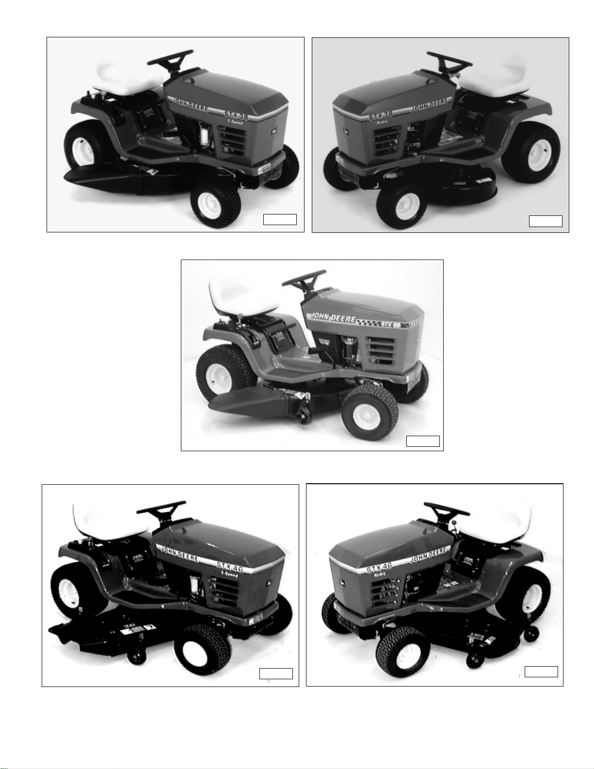
M55912
M55913
STX38 Gear Drive
STX38 Motorsport Edition
STX38 Hydrostatic Drive
M85680
M58332
M58333M58333
STX46 Hydrostatic DriveSTX46 Gear Drive
Page 3
This technical manual is written for an experienced
technician and contains sections that are specifically for
this product. It is a part of a total product support
program.
INTRODUCTION
Safety
Specifications and
Information
The manual is organized so that all the information on a
particular system is kept together. The order of grouping
is as follows:
• Table of Contents
• Specifications
• Theory of Operation
• Troubleshooting Diagram
• Diagnostics
• Tests & Adjustments
• Repair
Note: Depending on the particular section or system
being covered, not all of the above groups may be
used.
Each section will be identified with a symbol rather than a
number. The groups and pages within a section will be
consecutively numbered.
Engine
Electrical
Power Train
(Gear)
Power Train
Power Train
(Hydrostatic)
Steering
All information, illustrations and specifications in this
manual are based on the latest information available at
the time of publication. The right is reserved to make
changes at any time without notice.
We appreciate your input on this manual. To help, there
are postage paid post cards included at the back. If you
find any errors or want to comment on the layout of the
manual please fill out one of the cards and mail it back to
us.
©
COPYRIGHT
JOHN DEERE HORICON WORKS
Horicon, Wisconsin
All rights reserved
1997
Miscellaneous
3/12/97
1 - 1
Page 4
SAFETY
RECOGNIZE SAFETY
INFORMATION
This is the safety-alert symbol. When you see this
symbol on your machine or in this manual, be alert to
the potential for personal injury.
Follow recommended precautions and safe servicing
practices.
Understand Signal Words
HANDLE FLUIDS SAFELY-AVOID
FIRES
Be Prepared For Emergencies
A signal word—DANGER, WARNING, or CAUTION—
is used with the safety-alert symbol. DANGER
identifies the most serious hazards.
DANGER or WARNING safety signs are located near
specific hazards. General precautions are listed on
CAUTION safety signs. CAUTION also calls attention
to safety messages in this manual.
REPLACE SAFETY SIGNS
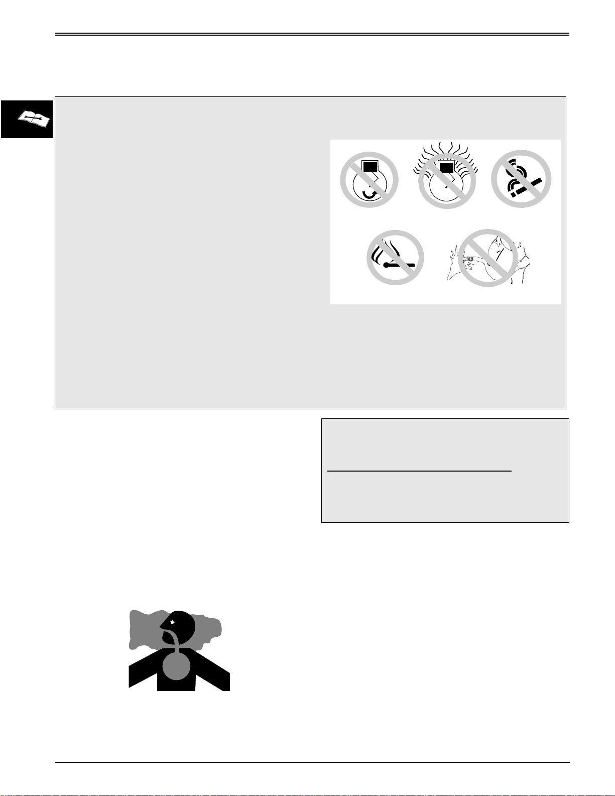
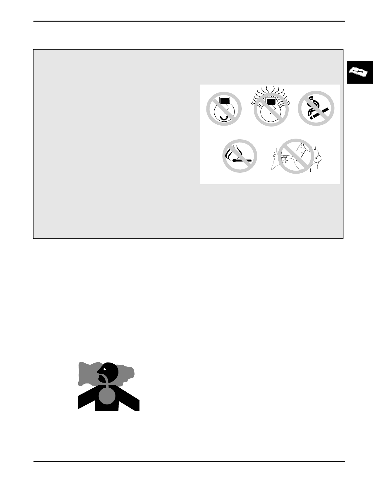
When you work around fuel, do not smoke or work near
heaters or other fire hazards.
Store flammable fluids away from fire hazards. Do not
incinerate or puncture pressurized containers.
Make sure machine is clean of trash, grease, and
debris.
Do not store oily rags; they can ignite and burn
spontaneously.
Be prepared if a fire starts.
Keep a first aid kit and fire extinguisher handy.
Keep emergency numbers for doctors, ambulance
service, hospital, and fire department near your
telephone.
Replace missing or damaged safety signs. See the
machine operator’s manual for correct safety sign
placement.
1 - 2
3/12/97
Page 5
SAFETY
USE CARE IN HANDLING AND
SERVICING BATTERIES
Prevent Battery Explosions
• Keep sparks, lighted matches, and open flame
away from the top of battery. Battery gas can
explode.
• Never check battery charge by placing a metal
object across the posts. Use a volt-meter or
hydrometer.
• Do not charge a frozen battery; it may explode.
Warm battery to 16°C (60°F).
Prevent Acid Burns
• Sulfuric acid in battery electrolyte is poisonous. It is
strong enough to burn skin, eat holes in clothing,
and cause blindness if splashed into eyes.
• Avoid acid burns by:
1. Filling batteries in a well-ventilated area.
2. Wearing eye protection and rubber gloves.
3. Avoiding breathing fumes when electrolyte is
added.
4. Avoiding spilling or dripping electrolyte.
5. Use proper jump start procedure.
USE CARE AROUND HIGHPRESSURE FLUID LINES
Avoid High-pressure Fluids
Escaping fluid under pressure can penetrate the skin
causing serious injury.
Avoid injury from escaping fluid under pressure by
stopping the engine and relieving pressure in the
system before disconnecting or connecting hydraulic or
other lines. Tighten all connections before applying
pressure.
Search for leaks with a piece of cardboard. Protect
hands and body from high pressure fluids.
If an accident occurs, see a doctor immediately. Any
fluid injected into the skin must be surgically removed
within a few hours or gangrene may result. Doctors
unfamiliar with this type of injury should reference a
knowledgeable medical source. Such information is
available from Deere & Company Medical Department
in Moline, Illinois, U.S.A.
Avoid Heating Near Pressurized
Fluid Lines
• If you spill acid on yourself:
1. Flush your skin with water.
2. Apply baking soda or lime to help neutralize the
acid.
3. Flush your eyes with water for 10_15 minutes.
4. Get medical attention immediately.
• If acid is swallowed:
1. Drink large amounts of water or milk.
2. Then drink milk of magnesia, beaten eggs, or
vegetable oil.
3. Get medical attention immediately.
3/12/97
Flammable spray can be generated by heating near
pressurized fluid lines, resulting in severe burns to
yourself and bystanders. Do not heat by welding,
soldering, or using a torch near pressurized fluid lines
or other flammable materials. Pressurized lines can be
accidentally cut when heat goes beyond the immediate
flame area.
1 - 3
Page 6
SAFETY
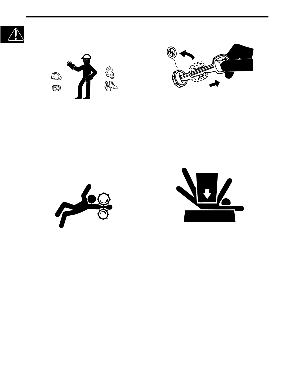
USE SAFE SERVICE PROCEDURES
Wear Protective Clothing
Wear close fitting clothing and safety equipment
appropriate to the job.
Prolonged exposure to loud noise can cause
impairment or loss of hearing. Wear a suitable hearing
protective device such as earmuffs or earplugs to
protect against objectionable or uncomfortable loud
noises.
Operating equipment safely requires the full attention
of the operator. Do not wear radio or music
headphones while operating machine.
Park Machine Safely
Before working on the machine:
1. Lower all equipment to the ground.
2. Stop the engine and remove the key.
3. Disconnect the battery ground strap.
4. Hang a “DO NOT OPERATE” tag in operator
station.
Support Machine Properly And Use
Proper Lifting Equipment
Service Machines Safely
Tie long hair behind your head. Do not wear a necktie,
scarf, loose clothing, or necklace when you work near
machine tools or moving parts. If these items were to
get caught, severe injury could result.
Remove rings and other jewelry to prevent electrical
shorts and entanglement in moving parts.
Use Proper Tools
Use tools appropriate to the work. Makeshift tools and
procedures can create safety hazards. Use power tools
only to loosen threaded parts and fasteners. For
loosening and tightening hardware, use the correct
size tools.
metric fasteners. Avoid bodily injury caused by slipping
wrenches. Use only service parts meeting John Deere
specifications.
DO NOT
use U.S. measurement tools on
If you must work on a lifted machine or attachment,
securely support the machine or attachment.
Do not support the machine on cinder blocks, hollow
tiles, or props that may crumble under continuous load.
Do not work under a machine that is supported solely
by a jack. Follow recommended procedures in this
manual.
Lifting heavy components incorrectly can cause severe
injury or machine damage. Follow recommended
procedure for removal and installation of components
in the manual.
Work In Clean Area
Before starting a job:
1. Clean work area and machine.
2. Make sure you have all necessary tools to do your
job.
3. Have the right parts on hand.
4. Read all instructions thoroughly; do not attempt
shortcuts.
1 - 4
3/12/97
Page 7
SAFETY
Using High Pressure Washers
Directing pressurized water at electronic/electrical
components or connectors, bearings, hydraulic seals,
fuel injection pumps or other sensitive parts and
components may cause product malfunctions. Reduce
pressure and spray at a 45 to 90 degree angle.
Illuminate Work Area Safely
Illuminate your work area adequately but safely. Use a
portable safety light for working inside or under the
machine. Make sure the bulb is enclosed by a wire
cage. The hot filament of an accidentally broken bulb
can ignite spilled fuel or oil.
Work In Ventilated Area
Avoid Harmful Asbestos Dust
Avoid breathing dust that may be generated when
handling components containing asbestos fibers.
Inhaled asbestos fibers may cause lung cancer.
Components in products that may contain asbestos
fibers are brake pads, brake band and lining
assemblies, clutch plates, and some gaskets. The
asbestos used in these components is usually found in
a resin or sealed in some way. Normal handling is not
hazardous as long as airborne dust containing
asbestos is not generated.
Avoid creating dust. Never use compressed air for
cleaning. Avoid brushing or grinding material
containing asbestos. When servicing, wear an
approved respirator. A special vacuum cleaner is
recommended to clean asbestos. If not available, apply
a mist of oil or water on the material containing
asbestos. Keep bystanders away from the area.
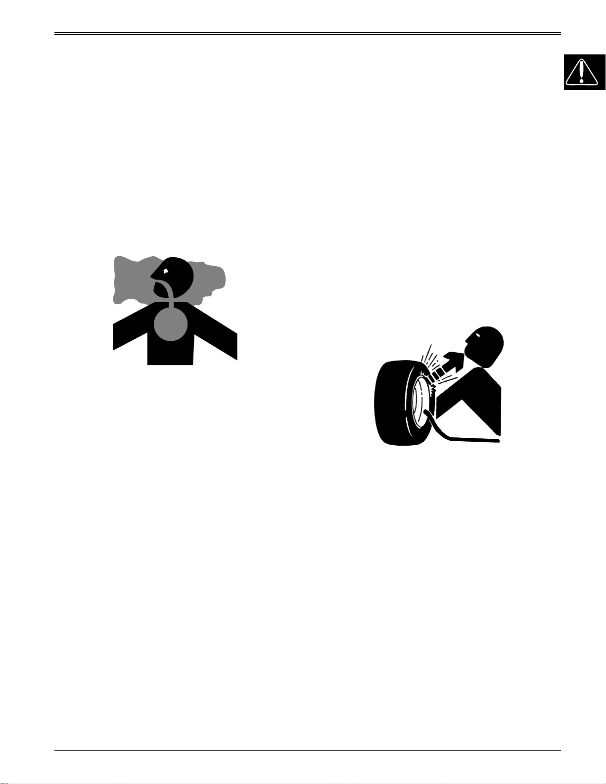
SERVICE TIRES SAFELY
Engine exhaust fumes can cause sickness or death. If
it is necessary to run an engine in an enclosed area,
remove the exhaust fumes from the area with an
exhaust pipe extension.
If you do not have an exhaust pipe extension, open the
doors and get outside air into the area.
WARNING: California Proposition 65
Warning
Diesel engine exhaust and some of its constituents are
known to the State of California to cause cancer, birth
defects, and other reproductive harm.
Gasoline engine exhaust from this product contains
chemicals known to the State of California to cause
cancer, birth defects, or other reproductive harm.
Remove Paint Before Welding Or
Heating
Avoid potentially toxic fumes and dust. Hazardous
fumes can be generated when paint is heated by
welding, soldering, or using a torch. Do all work outside
or in a well ventilated area. Dispose of paint and
solvent properly. Remove paint before welding or
heating: If you sand or grind paint, avoid breathing the
dust. Wear an approved respirator. If you use solvent
or paint stripper, remove stripper with soap and water
before welding. Remove solvent or paint stripper
containers and other flammable material from area.
Allow fumes to disperse at least 15 minutes before
welding or heating.
Explosive separation of a tire and rim parts can cause
serious injury or death.
Do not attempt to mount a tire unless you have the
proper equipment and experience to perform the job.
Always maintain the correct tire pressure. Do not inflate
the tires above the recommended pressure. Never
weld or heat a wheel and tire assembly. The heat can
cause an increase in air pressure resulting in a tire
explosion. Welding can structurally weaken or deform
the wheel.
When inflating tires, use a clip-on chuck and extension
hose long enough to allow you to stand to one side and
NOT in front of or over the tire assembly. Use a safety
cage if available.
Check wheels for low pressure, cuts, bubbles,
damaged rims or missing lug bolts and nuts.
3/12/97
1 - 5
Page 8
SAFETY
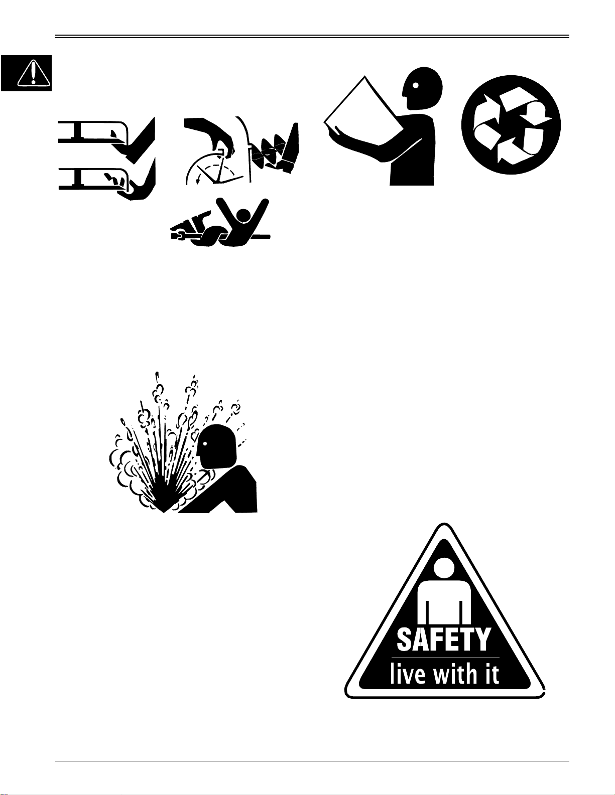
AVOID INJURY FROM ROTATING
BLADES, AUGERS AND PTO
SHAFTS
Keep hands and feet away while machine is running.
Shut off power to service, lubricate or remove mower
blades, augers or PTO shafts.
SERVICE COOLING SYSTEM
SAFELY
Direct exposure to hazardous chemicals can cause
serious injury. Potentially hazardous chemicals used
with John Deere equipment include such items as
lubricants, coolants, paints, and adhesives.
A Material Safety Data Sheet (MSDS) provides specific
details on chemical products: physical and health
hazards, safety procedures, and emergency response
techniques. Check the MSDS before you start any job
using a hazardous chemical. That way you will know
exactly what the risks are and how to do the job safely.
Then follow procedures and recommended equipment.
Dispose of Waste Properly
Explosive release of fluids from pressurized cooling
system can cause serious burns.
Shut off machine. Only remove filler cap when cool
enough to touch with bare hands. Slowly loosen cap to
first stop to relieve pressure before removing
completely.
HANDLE CHEMICAL PRODUCTS
SAFELY
Improperly disposing of waste can threaten the
environment and ecology. Potentially harmful waste
used with John Deere equipment include such items as
oil, fuel, coolant, brake fluid, filters, and batteries. Use
leakproof containers when draining fluids. Do not use
food or beverage containers that may mislead
someone into drinking from them. Do not pour waste
onto the ground, down a drain, or into any water
source. Inquire on the proper way to recycle or dispose
of waste from your local environmental or recycling
center, or from your John Deere dealer.
LIVE WITH SAFETY
1 - 6
Before returning machine to customer, make sure
machine is functioning properly, especially the safety
systems. Install all guards and shields.
3/12/97
Page 9

SPECIFICATIONS & INFORMATION
GENERAL VEHICLE SPECIFICATIONS . . . . . . . . . . . . . . . . . . . . . . . . . 3
METRIC FASTENER TORQUE VALUES. . . . . . . . . . . . . . . . . . . . . . . . . 6
METRIC FASTENER TORQUE VALUE - GRADE 7. . . . . . . . . . . . . . . . . . . . . . . . . . 7
INCH FASTENER TORQUE VALUES . . . . . . . . . . . . . . . . . . . . . . . . . . . 8
O-RING SEAL SERVICE RECOMMENDATIONS . . . . . . . . . . . . . . . . . . 9
FACE SEAL FITTINGS WITH INCH STUD ENDS TORQUE . . . . . . . . . . . . . . . . . . . 9
FACE SEAL FITTINGS WITH METRIC STUD ENDS TORQUE . . . . . . . . . . . . . . . 10
O-RING FACE SEAL FITTINGS . . . . . . . . . . . . . . . . . . . . . . . . . . . . . . . . . . . . . . . . 11
O-RING BOSS FITTINGS . . . . . . . . . . . . . . . . . . . . . . . . . . . . . . . . . . . . . . . . . . . . . 11
GASOLINE SPECIFICATIONS. . . . . . . . . . . . . . . . . . . . . . . . . . . . . . . . 12
4–CYCLE ENGINES - NORTH AMERICA . . . . . . . . . . . . . . . . . . . . . . . . . . . . . . . . 12
GASOLINE STORAGE . . . . . . . . . . . . . . . . . . . . . . . . . . . . . . . . . . . . . . . . . . . . . . . 12
4–CYCLE ENGINES - EUROPE. . . . . . . . . . . . . . . . . . . . . . . . . . . . . . . . . . . . . . . . 13
GASOLINE STORAGE . . . . . . . . . . . . . . . . . . . . . . . . . . . . . . . . . . . . . . . . . . . . . . . 13
4–CYCLE GASOLINE ENGINE OIL. . . . . . . . . . . . . . . . . . . . . . . . . . . . 14
4–CYCLE GASOLINE ENGINE OIL - NORTH AMERICA . . . . . . . . . . . . . . . . . . . . 14
4–CYCLE GASOLINE ENGINE OIL - EUROPE . . . . . . . . . . . . . . . . . . . . . . . . . . . . 15
BREAK–IN 4-CYCLE GASOLINE ENGINE OIL - NORTH AMERICA . . . . . . . . . . . 16
BREAK–IN 4-CYCLE GASOLINE ENGINE OIL - EUROPE . . . . . . . . . . . . . . . . . . . 17
HYDROSTATIC TRANSMISSION OIL. . . . . . . . . . . . . . . . . . . . . . . . . . 18
HYDROSTATIC TRANSMISSION OIL - NORTH AMERICA . . . . . . . . . . . . . . . . . . 18
HYDROSTATIC TRANSMISSION OIL - EUROPE . . . . . . . . . . . . . . . . . . . . . . . . . . 19
ALTERNATIVE LUBRICANTS. . . . . . . . . . . . . . . . . . . . . . . . . . . . . . . . 20
SYNTHETIC LUBRICANTS. . . . . . . . . . . . . . . . . . . . . . . . . . . . . . . . . . . . . . . . . . . . 20
LUBRICANT STORAGE . . . . . . . . . . . . . . . . . . . . . . . . . . . . . . . . . . . . . . . . . . . . . . 20
MIXING OF LUBRICANTS . . . . . . . . . . . . . . . . . . . . . . . . . . . . . . . . . . . . . . . . . . . . 20
OIL FILTERS. . . . . . . . . . . . . . . . . . . . . . . . . . . . . . . . . . . . . . . . . . . . . . . . . . . . . . . 20
GEAR TRANSMISSION GREASE . . . . . . . . . . . . . . . . . . . . . . . . . . . . . 21
ANTI-CORROSION GREASE SPECIFICATIONS . . . . . . . . . . . . . . . . . 22
GREASE SPECIFICATIONS . . . . . . . . . . . . . . . . . . . . . . . . . . . . . . . . . 23
GREASE - NORTH AMERICA . . . . . . . . . . . . . . . . . . . . . . . . . . . . . . . . . . . . . . . . . 23
GREASE - EUROPE . . . . . . . . . . . . . . . . . . . . . . . . . . . . . . . . . . . . . . . . . . . . . . . . . 23
SERIAL NUMBER LOCATIONS. . . . . . . . . . . . . . . . . . . . . . . . . . . . . . . 24
ENGINE SERIAL NUMBER SUFFUX. . . . . . . . . . . . . . . . . . . . . . . . . . . . . . . . . . . . 24
TRACTOR IDENTIFICATION NUMBER. . . . . . . . . . . . . . . . . . . . . . . . . . . . . . . . . . 24
ENGINE SERIAL NUMBER. . . . . . . . . . . . . . . . . . . . . . . . . . . . . . . . . . . . . . . . . . . . 24
GEAR TRANSAXLE SERIAL NUMBER . . . . . . . . . . . . . . . . . . . . . . . . . . . . . . . . . . 24
HYDROSTATIC TRANSMISSION SERIAL NUMBER . . . . . . . . . . . . . . . . . . . . . . . 24
CONTENTS
CONTENTS
Page
SPECIFICATIONS & INFORMATION
3/12/97
2 - 1
Page 10

NOTES
SPECIFICATIONS & INFORMATION
2 - 2
3/12/97
Page 11

SPECIFICATIONS AND INFORMATION
GENERAL VEHICLE SPECIFICATIONS
Engine:
Make . . . . . . . . . . . . . . . . . . . . . . . . . . . . . . . . . . . . . . . . . . . . . . . . . . . . . . . . . . . Kohler
Style . . . . . . . . . . . . . . . . . . . . . . . . . . . . . . . . . . . . . . . . . . . . . . . . . . . . . .Command LT
STX30 . . . . . . . . . . . . . . . . . . . . . . . . . . . . . . . . . . . . . . . . . . . . . . . . . .CV12.5—1216s
STX38 (Serial No. —270000) . . . . . . . . . . . . . . . . . . . . . . . . . . . .CV12.5—1215
STX38 (Serial No. 210001—270000) . . . . . . . . . . . . . . . . . . . . . . . . . . . .CV12.5—1270
STX38 (Serial No. 270001—595000 & Motorsport) . . . . . . . . . . . . . . . . CV13S—21509
STX46 (Serial No. 210001—270000) . . . . . . . . . . . . . . . . . . . . . . . . . . . . CV14S—1463
STX46 (Serial No. 270001—595000) . . . . . . . . . . . . . . . . . . . . . . . . . . . CV15S—41521
Type . . . . . . . . . . . . . Gasoline, Air Cooled, Single Cylinder, 4-Cycle, Overhead Valves
Crankcase Oil Capacity (with filter). . . . . . . . . . . . . . . . . . . . . . . . . . . 1.8 L (1.9 U.S. qt)
Oil Type: (Warm Climate) . . . . . . . . . . . . . . . . . . . . . . . . . . . . . . . . . . . . . . . . . . .10W30
(Cold Climate). . . . . . . . . . . . . . . . . . . . . . . . . . . . . . . . . . . . . . . . . . . . . .5W30
Electrical:
Charging System. . . . . . . . . . . . . . . . . . . . . . . . . . . . . . . . Flywheel/Electronic Magneto
Magneto Air Gap. . . . . . . . . . . . . . . . . . . . . . . . . . . . . . 0.2—0.3 mm (0.008—0.012 in.)
Charging Capacity. . . . . . . . . . . . . . . . . . . . . . . . . . . . . . . . . . . . . . . 15 amp (regulated)
Spark Plug. . . . . . . . . . . . . . . . . . . . . . . . . . . . . . . . . . . . . . . . . . . . .Champion RC12YC
Spark Plug Air Gap . . . . . . . . . . . . . . . . . . . . . . . . . . . . . . . . . . . . . . .1.0 mm (0.040 in.)
Battery Type . . . . . . . . . . . . . . . . . . . . . . . . . . . . . . . . . . . . . . . . . . . . . . .BCI Group, U1
Battery Reserve Capacity . . . . . . . . . . . . . . . . . . . . . . . . . . . . . . . . . . 23 min. at 25 amp
Battery Cold Cranking Amp. . . . . . . . . . . . . . . . . .25 amp at 27° C (0° F) for 20 minutes
Battery Specific Gravity. . . . . . . . . . . . . . . . . . . . . . . . . . . . . . . . . . .Above 1.225 Points
Starter Type . . . . . . . . . . . . . . . . . . . . . . . . . . . . . . . . . . . . . . . . . . .Bendix Inertia Drive
PTO Clutch Type. . . . . . . . . . . . . . . . . . . . . . . . . . . . Electric (Manufactured by Warner)
Fuel Shut-Off Solenoid (Optional). . . . . . . . Replaceable (Below Carburetor Float Bowl)
Headlight Kit (Optional). . . . . . . . . . . . . . Two Bulbs—Each 12 Volt/23W/1.9 Amp Draw
Fuel/Air System:
Carburetor Make. . . . . . . . . . . . . . . . . . . . . . . . . . . . . . . . . . . . . . . . . . . . . . . . . .Walbro
Carburetor Type . . . . . . . . . . . . . . . . . . . . . . . . . . . . . . . . . . . . . . . . . . . . . . . Side Draft
Throttle/Choke. . . . . . . . . . . . . . . . . . . . . . . . . . . . . . . . . . . . . . Unitized Control Linkage
Carburetor Fuel Shut-Off Solenoid (Optional). . . . . . . . . . . . . . . . . . . . . . . . . . . .Electric
Fuel Delivery. . . . . . . . . . . . . . . . . . . . . . . . . . . . . . . . . . . . . . . . . . . . . . . . Gravity Flow
Fuel Filter . . . . . . . . . . . . . . . . . . . . . . . . . . . . . . . . . . .Replaceable Paper (in-line type)
Fuel Type . . . . . . . . . . . . . . . . . . . . . . . . . . . . . . . . . . . Unleaded (87 octane minimum)
Fuel Tank Capacity. . . . . . . . . . . . . . . . . . . . . . . . . . . . . . . . . . . . . . . . . 4.7 L (1.25 gal)
Air Filter. . . . . . . . . . . . . . . . . . . . . . . . . . . . . . . . Paper Element with Foam Pre-cleaner
Muffler Type . . . . . . . . . . . . . . . . . . . . . . . . . . . . . . . . . . . . . . . . . . . . . . . . Anti-Backfire
Power Train:
Gear Transaxle—
Make . . . . . . . . . . . . . . . . . . . . . . . . . . . . . . . . . . . . . . . . . . . . . . . . . . . . . . . . . . . . Dana
Model . . . . . . . . . . . . . . . . . . . . . . . . . . . . . . . . . . . .Spicer Heavy-Duty 4360 Transaxle
Type . . . . . . . . . . . . . . . . . . . . . . . . . . . . . . . . . . . . . . . . . . . . . .Five-Speed/Linear Shift
Domestic Ground Speeds (at FAST idle—3350 rpm) and Gear Ratios:
1st Gear . (STX30 & STX38 SN —210000 2.2km/hr) 2.4 km/hr (1.5 mph)—61.67:1
2nd Gear. . . . . . . . . . . . . . . . . . . . . . . . . . . . . . . . . . . . . 3.2 km/hr (2.0 mph)—46.67:1
3rd Gear . (STX30 & STX38 SN —210000 4.5km/hr) 5.0 km/hr (3.1 mph)—30.00:1
4th Gear . (STX30 & STX38 SN —210000 5.7km/hr) 6.4 km/hr (4.0 mph)—23.48:1
5th Gear . (STX30 & STX38 SN —210000 8.5km/hr) 8.0 km/hr (5.0 mph)—15.71:1
Reverse . .(STX30 & STX38 SN —210000 3.3km/hr) 3.7 km/hr (2.3 mph)—40.00:1
Export Ground Speeds (at FAST idle—3000 rpm) and Gear Ratios:
1st Gear . . . . . . . . . . . . . . . . . . . . . . . . . . . . . . . . . . . 1.97 km/hr (1.22 mph)—61.67:1
2nd Gear. . . . . . . . . . . . . . . . . . . . . . . . . . . . . . . . . . . 2.61 km/hr (1.67 mph)—46.67:1
3rd Gear . . . . . . . . . . . . . . . . . . . . . . . . . . . . . . . . . . . 4.07 km/hr (2.53 mph)—30.00:1
4th Gear . . . . . . . . . . . . . . . . . . . . . . . . . . . . . . . . . . . 5.18 km/hr (3.22 mph)—23.48:1
5th Gear . . . . . . . . . . . . . . . . . . . . . . . . . . . . . . . . . . . 7.76 km/hr (4.82 mph)—15.71:1
Reverse . . . . . . . . . . . . . . . . . . . . . . . . . . . . . . . . . . . 3.04 km/hr (1.89 mph)—40.00:1
Brake Type . . . . . . . . . . . . . . . . . .Single, External Brake Disc With Dual Friction Pucks
GENERAL VEHICLE SPECIFICATIONS
3/20/97
2 - 3
Page 12

GENERAL VEHICLE SPECIFICATIONS
Power Train: (Continued)
Lubrication—Input Shaft Needle Bearings . . . . . . . . . . . . . . . .Unirex® N3 Grease Only
Lubrication—Transaxle. . . . . . . . . . . . . . . . . . . . . . . . . . . Shell Darina® D Grease Only
Capacity—Transaxle. . . . . . . . . . . . . . . . . . . . . . . . . . . . . . . . . . . . . .0.64 kg (1.406 lbs)
Hydro Transaxle—
Make . . . . . . . . . . . . . . . . . . . . . . . . . . . . . . . . . . . . . . . . . . . . . . . . . . . . . . . . . . Kanzaki
Model (STX38—early models) . . . . . . . . . . . . . . . . . . . . . . . .Tuff Torq® K50 Transaxle
Model (STX38—late models) . . . . . . . . . . . . . . . . . . . . . . . . .Tuff Torq® K55 Transaxle
Model (STX46) . . . . . . . . . . . . . . . . . . . . . . . . . . . . . . . . . . . .Tuff Torq® K55 Transaxle
Type . . . . . . . . . . . . . . . . . . . . . . . . . . . . . . . . . . . . . . . . . . . . . . . . . . . . . . . Hydrostatic
Domestic Ground Speeds (at FAST idle—3350 rpm):
Forward . . . . . . . . . . . . . . . . . . . . . . . . . . . . . . . . . . . . . . . 0—9.3 km/hr (0—5.8 mph)
Reverse . . . . . . . . . . . . . . . . . . . . . . . . . . . . . . . . . . . . . . . 0—4.7 km/hr (0—2.9 mph)
Export Ground Speeds (at FAST idle—3000 rpm):
Forward . . . . . . . . . . . . . . . . . . . . . . . . . . . . . . . . . . . . . 0—7.75 km/hr (0—4.82 mph)
Reverse . . . . . . . . . . . . . . . . . . . . . . . . . . . . . . . . . . . . . 0—3.80 km/hr (0—2.36 mph)
Brake Type . . . . . . . . . . . . . . . . . . . . . .Single, External Disc Brake With Friction Pucks
Lubrication. . . . . . . . . . . . . . . . . . . . . . John Deere Plus-4 10W30 Engine Oil, Class CD
Reservoir. . . . . . . . . . . . . . . . . . . . . . . . . . . . . . . . . . . . . . . . . . . . . . . . . . . . . . . Internal
Capacity . . . . . . . . . . . . . . . . . . . . . . . . . . . . . . . . . . . . . . . . . . . . . . . . . . . 1.6 L (3.4 pt)
SPECIFICATIONS AND INFORMATION
Traction Drive Belt:
Gear—
Actual effective length . . . . . . . . . . . . . . . . . . . . . . . . . . . . .2660±8 mm (104.7±0.3 in.)
Theoretical effective length (short) . . . . . . . . . . . . . . . . . . . . . . . . . 2631 mm (103.6 in.)
Theoretical effective length (long). . . . . . . . . . . . . . . . . . . . . . . . . . 2710 mm (106.7 in.)
Hydro—
Actual effective length . . . . . . . . . . . . . . . . . . . . . . . . . . . . . .2485±8 mm (97.8±0.3 in.)
Theoretical effective length (short) . . . . . . . . . . . . . . . . . . . . . . . . . . 2477 mm (97.5 in.)
Theoretical effective length (long). . . . . . . . . . . . . . . . . . . . . . . . . . . 2530 mm (99.6 in.)
Mower Deck Drive Belt
38-Inch Deck—
Actual effective length . . . . . . . . . . . . . . . . . . . . . . . . . . . . .2425±10 mm (95.5±0.4 in.)
46-Inch Deck—
Actual effective length . . . . . . . . . . . . . . . . . . . . . . . . . . . .3492±10 mm (137.5±0.4 in.)
Mower Deck:
38-Inch Mower Deck—
Type . . . . . . . . . . . . . . . . . . . . . . . . . . . . . . . Rotary—Dual Spindles (Non-Serviceable)
Material Type . . . . . . . . . . . . . . . . . .Stamped 2.5 mm (0.098 in.) Nominal Gauge Steel
Cutting Blade. . . . . . . . . . . . . . . . . . . . . . . . . Two—76 x 5 x 496 mm (3 x 0.2 x 19.5 in.)
Blade Cutting Edge. . . . . . . . . . . . . . . . . . . . . . . . . . . . . . . . . . . . . . . . . . . .30±5° Angle
Blade Wing Lift/Height. . . . . . . . . . . . . . . . . . . . . . . . . . . . . . . .40±3 mm (1.57±0.12 in.)
Overall Cutting Width . . . . . . . . . . . . . . . . . . . . . . . . . . . . . . . . . . . . . . . 965 mm (38 in.)
Overall Width (w/o discharge chute). . . . . . . . . . . . . . . . . . . . . . . . . 1026 mm (40.4 in.)
Drive Type. . . . . . . . . . . . . . . . . . . . . . . . . . . Single V-Belt (with spring-tensioned idler)
Spindle Lubrication . . . . . . . . . . . . . . . . . . . . . . . . . . . . . . . . . . None—Sealed Bearings
Lift Type . . . . . . . . . . . . . . . . . . . . . . . . . . . . . . . . . . . . . . . Manual—Operator’s Station
Cutting Settings. . . . . . . . . . . . . . . . . . . . . . . . . . . .Seven: 31.8—89 mm (1.25—3.5 in.)
2 - 4
3/20/97
Page 13

SPECIFICATIONS AND INFORMATION
Mower Deck: (Continued)
46-Inch Mower Deck—
Type. . . . . . . . . . . . . . . . . . . . . . . . . . . . . . . Rotary—Triple Spindles (Non-Serviceable)
Material Type . . . . . . . . . . . . . . . . . . Stamped 2.5 mm (0.098 in.) Nominal Gauge Steel
Cutting Blade . . . . . . . . . . . . . . . . . . . . . .Three—50.8 x 5 x 407.4 mm (2 x 0.2 x 16 in.)
Blade Cutting Edge . . . . . . . . . . . . . . . . . . . . . . . . . . . . . . . . . . . . . . . . . . . 30±5° Angle
Blade Wing Lift/Height . . . . . . . . . . . . . . . . . . . . . . . . . . . . . . .20.3±3 mm (0.8±0.12 in.)
Overall Cutting Width. . . . . . . . . . . . . . . . . . . . . . . . . . . . . . . . . . . . . 1168.4 mm (46 in.)
Overall Width (w/o discharge chute) . . . . . . . . . . . . . . . . . . . . . . . . . 1308 mm (51.5 in.)
Drive Type . . . . . . . . . . . . . . . . . . . . . . . . . . . Single V-Belt (with spring-tensioned idler)
Spindle Lubrication. . . . . . . . . . . . . . . . . . . . . . . . . . . . . . . . . . None—Supplier Fill Only
Lift Type . . . . . . . . . . . . . . . . . . . . . . . . . . . . . . . . . . . . . . . . Manual—Operator’s Station
Cutting Settings . . . . . . . . . . . . . . . . . . . . . . .Seven: 31.75 mm—89 mm (1.25—3.5 in.)
Chassis:
Wheelbase. . . . . . . . . . . . . . . . . . . . . . . . . . . . . . . . . . . . . . . . . . . . 1135 mm (44.69 in.)
Overall Length . . . . . . . . . . . . . . . . . . . . . . . . . . . . . . . . . . . . . . . . . . . 1524 mm (60 in.)
Overall Width (w/o mower deck) . . . . . . . . . . . . . . . . . . . . . . . . . . . . 908 mm (35.75 in.)
Height. . . . . . . . . . . . . . . . . . . . . . . . . . . . . . . . . . . . . . . . . . . . . . . . . .980 mm (38.6 in.)
Average Overall Weight STX38 (with mower deck/no fuel). . . . . . . .195.05 kg (430 lbs)
Average Overall Weight STX46 (with mower deck/no fuel). . . . . . . .204.12 kg (450 lbs)
Hitch Capacity—
Export:
Horizontal Pull Maximum . . . . . . . . . . . . . . . . . . . . . . . . . . . . . . . . . . .250 N (56 lbs)
Tongue Weight Maximum . . . . . . . . . . . . . . . . . . . . . . . . . . . . . . . . . . .65 N (15 lbs)
Domestic:
Trailer Load Maximum . . . . . . . . . . . . . . . . . . . . . . . . . . . . . . . . . . . 136 kg (300 lbs)
Trailer Tongue Weight Maximum. . . . . . . . . . . . . . . . . . . . . . . . . . . . . 23 kg (50 lbs)
GENERAL VEHICLE SPECIFICATIONS
Steering:
Type. . . . . . . . . . . . . . . . . . . . . . . . . . . . . . . . . . . . . . . . . . . . . . .Manual—Pinion/Sector
Axle Pivot Hub . . . . . . . . . . . . . . . . . . . . . . . . . . . . . . . . . . . . . . . . . . . . Shim Adjustable
Lubrication . . . . . . . . . . . . . . . . . . . . . . . . . . . . . DuBois MPG-2® Multipurpose Grease
Lubrication Interval. . . . . . . . . . . . . . . . . . . . . . . . . . . . . . . . . . . . . . . 10 hrs (maximum)
Toe-In. . . . . . . . . . . . . . . . . . . . . . . . . . . . . . . . . . . . .6 mm (0.24 in.) — Non-Adjustable
Turning Radius. . . . . . . . . . . . . . . . . . . . . . . . . . . . . . . . . . . . . . . . . . . . 584 mm (23 in.)
Wheels:
Size—
Front . . . . . . . . . . . . . . . . . . . . . . . . . . . . . . . . . . . . . . . . . . . . . . . . . . . . . . . 6.0 x 4.50
Rear. . . . . . . . . . . . . . . . . . . . . . . . . . . . . . . . . . . . . . . . . . . . . . . . . . . . . . . . 8.0 x 6.18
Tires:
Size—
Front (STX30) . . . . . . . . . . . . . . . . . . . . . . . . . . . . . . . . . . . . . . 13 x 5—6 NHS (2 ply)
Rear (STX30) . . . . . . . . . . . . . . . . . . . . . . . . . . . . . . . . . . . . 18 x 6.50—8 NHS (2 ply)
Front (STX38 SN —210000) . . . . . . . . . . . . . . . . . . . . . . . 13 x 6.50—6 NHS (2 ply)
Rear (STX38 SN —210000). . . . . . . . . . . . . . . . . . . . . . . . 18 x 8.50—8 NHS (2 ply)
Front (STX38 SN 210001—270000). . . . . . . . . . . . . . . . . . . 13 x 6.50—6 NHS (2 ply)
Rear (STX38 SN 210001—270000) . . . . . . . . . . . . . . . . . . . 18 x 9.50—8 NHS (2 ply)
Front (STX38 SN 270001—595000 & STX46) . . . . . . . . . . . 15 x 6.50—6 NHS (2 ply)
Rear (STX38 SN 270001—595000 & STX46) . . . . . . . . . . . 20 x 8.00—8 NHS (2 ply)
Pressure—
Front (with mower deck) . . . . . . . . . . . . . . . . . . . . . . . . . . . . . . . . . . . . 83 kPa (12 psi)
Front (with snowthrower). . . . . . . . . . . . . . . . . . . . . . . . . . . . . . . . . . . 138 kPa (20 psi)
Rear (STX30 with mower deck). . . . . . . . . . . . . . . . . . . . . . . . . . . . . . . 97 kPa (14 psi)
Rear (with mower deck). . . . . . . . . . . . . . . . . . . . . . . . . . . . . . . . . . . . . . 55 kPa (8 psi)
3/20/97
2 - 5
Page 14
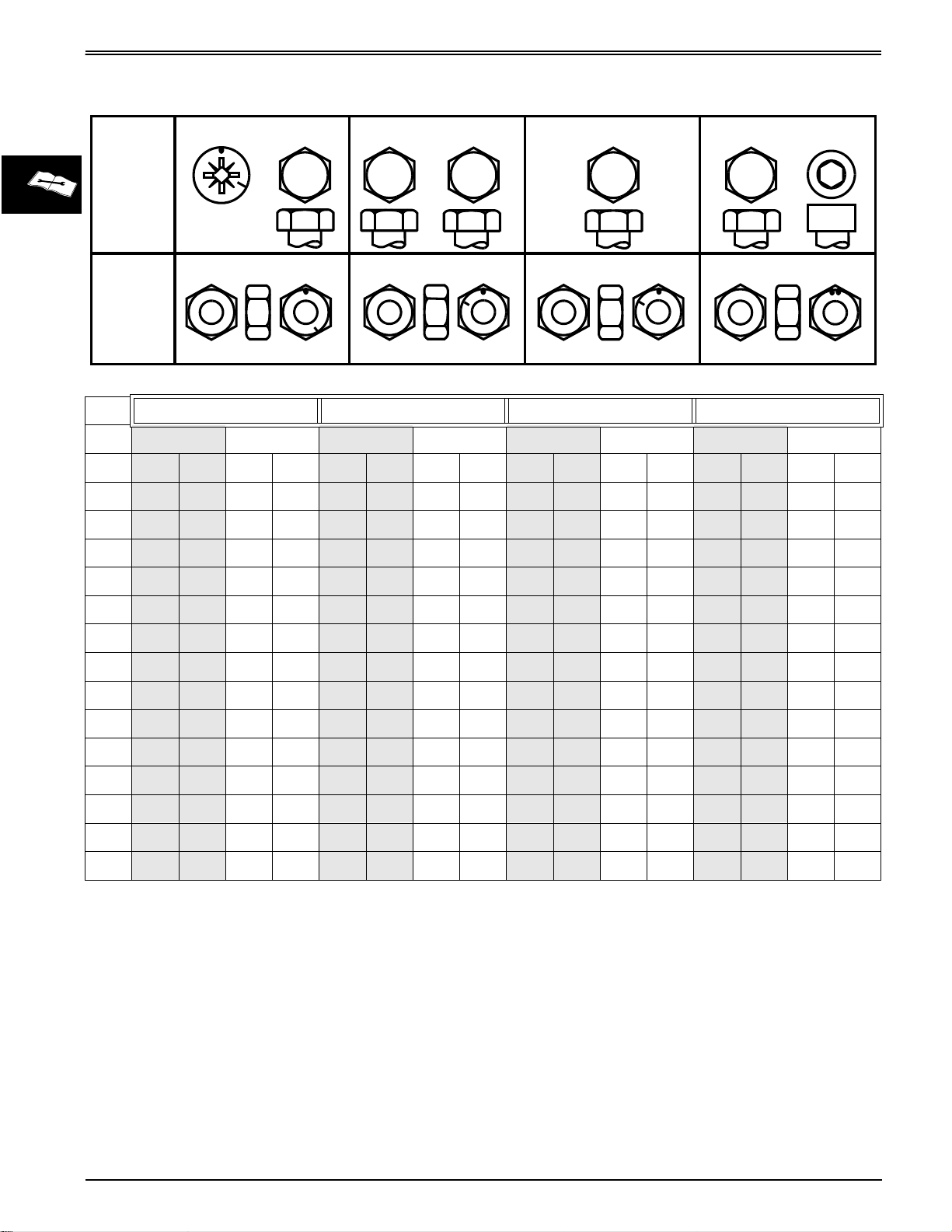
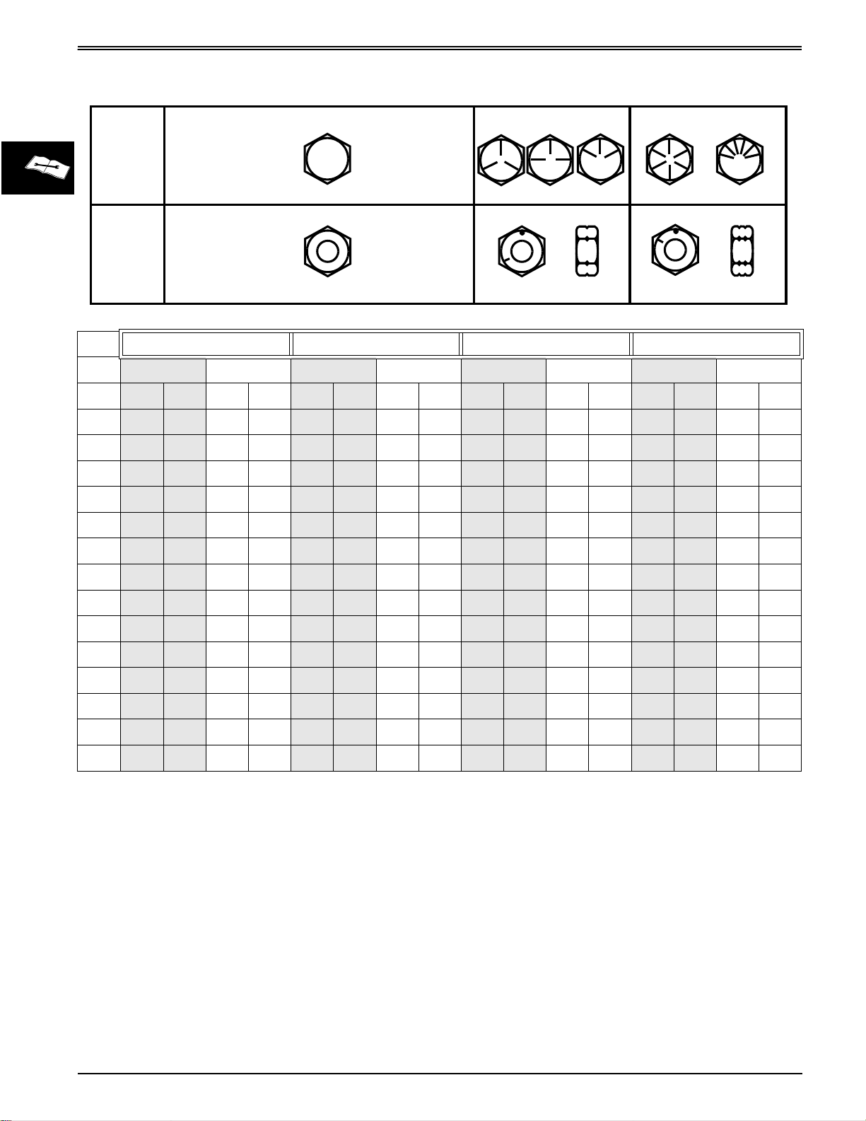
METRIC FASTENER TORQUE VALUES
METRIC FASTENER TORQUE VALUES
SPECIFICATIONS AND INFORMATION
4.8
8.8
9.8
10.9
12.9
Property
Class
and
4.8
8.8
9.8
10.9
12.9
Head
Markings
Property
4.8
5
8.8
10
9.8
10.9
10
12.9
12.9
12
Class
and
Nut
Markings
Class 4.8 Class 8.8 or 9.8 Class 10.9 Class 12.9
Lubricated
SIZE N•m lb-ft N•m lb-ft N•m lb-ft N•m lb-ft N•m lb-ft N•m lb-ft N•m lb-ft N•m lb-ft
M6
M8
M10
M12
4.8 3.5 6 4.5 9 6.5 11 8.5 13 9.5 17 12 15 11.5 19 14.5
12 8.5 15 11 22 16 28 20 32 24 40 30 37 28 47 35
23 17 29 21 43 32 55 40 63 47 80 60 75 55 95 70
40 29 50 37 75 55 95 70 110 80 140 105 130 95 165 120
5
a
Dry
5
10
a
Lubricated
a
Dry
a
10
10
Lubricated
10
12
a
Dry
a
Lubricated
12
TS1163
a
Dry
a
M14
M16
M18
M20
M22
M24
M27
M30
M33
M36
63 47 80 60 120 88 150 110 175 130 225 165 205 150 260 109
100 73 125 92 190 140 240 175 275 200 350 225 320 240 400 300
135 100 175 125 260 195 330 250 375 275 475 350 440 325 560 410
190 140 240 180 375 275 475 350 530 400 675 500 625 460 800 580
260 190 330 250 510 375 650 475 725 540 925 675 850 625 1075 800
330 250 425 310 650 475 825 600 925 675 1150 850 1075 800 1350 1000
490 360 625 450 950 700 1200 875 1350 1000 1700 1250 1600 1150 2000 1500
675 490 850 625 1300 950 1650 1200 1850 1350 2300 1700 2150 1600 2700 2000
900 675 1150 850 1750 1300 2200 1650 2500 1850 3150 2350 2900 2150 3700 2750
1150 850 1450 1075 2250 1650 2850 2100 3200 2350 4050 3000 3750 2750 4750 3500
DO NOT use these hand torque values if a different
torque value or tightening procedure is given for a
specific application. Torque values listed are for
general use only and include a ±10% variance factor.
Check tightness of fasteners periodically. DO NOT use
air powered wrenches.
Shear bolts are designed to fail under predetermined
loads. Always replace shear bolts with identical grade.
Fasteners should be replaced with the same class.
Make sure fastener threads are clean and that you
properly start thread engagement. This will prevent
them from failing when tightening.
When bolt and nut combination fasteners are used,
torque values should be applied to the
NUT
instead of
the bolt head.
Tighten toothed or serrated-type lock nuts to the full
torque value.
a
“Lubricated” means coated with a lubricant such
as engine oil, or fasteners with phosphate and oil
coatings. “Dry” means plain or zinc plated (yellow
dichromate - Specification JDS117) without any
lubrication
Reference: JDS—G200.
.
2 - 6
3/20/97
Page 15

SPECIFICATIONS AND INFORMATION
METRIC FASTENER TORQUE
VALUE - GRADE 7
METRIC FASTENER TORQUE VALUES
Steel or Gray
Size
M6 11 8 8 6
M8 24 18 19 14
M10 52 38 41 30
M12 88 65 70 52
M14 138 102 111 82
M16 224 165 179 132
Iron Torque
N•m lb-ft N•m lb-ft
Aluminum
Torque
3/20/97
2 - 7
Page 16
INCH FASTENER TORQUE VALUES
INCH FASTENER TORQUE VALUES
SPECIFICATIONS AND INFORMATION
SAE
1 or 2
b
5
5.1
5.2
8
8.2
Grade
and Head
No Marks
Markings
2
5
8
SAE
Grade
and Nut
No Marks
Markings
TS1162
Grade 1 Grade 2
Lubricated
SIZE N•m lb-ft N•m lb-ft N•m lb-ft N•m lb-ft N•m lb-ft N•m lb-ft N•m lb-ft N•m lb-ft
1/4
5/16
3/8
7/16
1/2
3.7 2.8 4.7 3.5 6 4.5 7.5 5.5 9.5 712913.5 10 17 12.5
7.7 5.5 10 7 12 9151120 15 25 18 28 21 35 26
14 10 17 13 22 16 27 20 35 26 44 33 50 36 63 46
22 16 28 20 35 26 44 32 55 41 70 52 80 58 100 75
33 25 42 31 53 39 67 50 85 63 110 80 120 90 150 115
a
Dry
a
b
Lubricated
Grade 5, 5.1 or 5.2 Grade 8 or 8.2
a
Dry
a
Lubricated
a
Dry
a
Lubricated
a
Dry
a
9/16
5/8
3/4
7/8
1
1-1/8
1-1/4
1-3/8
1-1/2
48 36 60 45 75 56 95 70 125 90 155 115 175 130 225 160
67 50 85 62 105 78 135 100 170 125 215 160 215 160 300 225
120 87 150 110 190 140 240 175 300 225 375 280 425 310 550 400
190 140 240 175 190 140 240 175 490 360 625 450 700 500 875 650
290 210 360 270 290 210 360 270 725 540 925 675 1050 750 1300 975
470 300 510 375 470 300 510 375 900 675 1150 850 1450 1075 1850 1350
570 425 725 530 570 425 725 530 1300 950 1650 1200 2050 1500 2600 1950
750 550 950 700 750 550 950 700 1700 1250 2150 1550 2700 2000 3400 2550
1000 725 1250 925 990 725 1250 930 2250 1650 2850 2100 3600 2650 4550 3350
DO NOT use these hand torque values if a different
torque value or tightening procedure is given for a
specific application. Torque values listed are for
general use only and include a ±10% variance factor.
Check tightness of fasteners periodically. DO NOT use
air powered wrenches.
Shear bolts are designed to fail under predetermined
loads. Always replace shear bolts with identical grade.
Fasteners should be replaced with the same grade.
Make sure fastener threads are clean and that you
properly start thread engagement. This will prevent
them from failing when tightening.
When bolt and nut combination fasteners are used,
torque values should be applied to the
NUT
instead of
the bolt head.
Tighten toothed or serrated-type lock nuts to the full
torque value.
a
“Lubricated” means coated with a lubricant such
as engine oil, or fasteners with phosphate and oil
coatings. “Dry” means plain or zinc plated (yellow
dichromate - Specification JDS117) without any
.
lubrication
b
“Grade 2” applies for hex cap screws (not hex
bolts) up to 152 mm (6-in.) long. “Grade 1”
applies for hex cap screws over 152 mm (6-in.)
long, and for all other types of bolts and screws
of any length.
Reference: JDS—G200.
2 - 8
3/20/97
Page 17
SPECIFICATIONS AND INFORMATION
O-RING SEAL SERVICE RECOMMENDATIONS
O-RING SEAL
SERVICE RECOMMENDATIONS
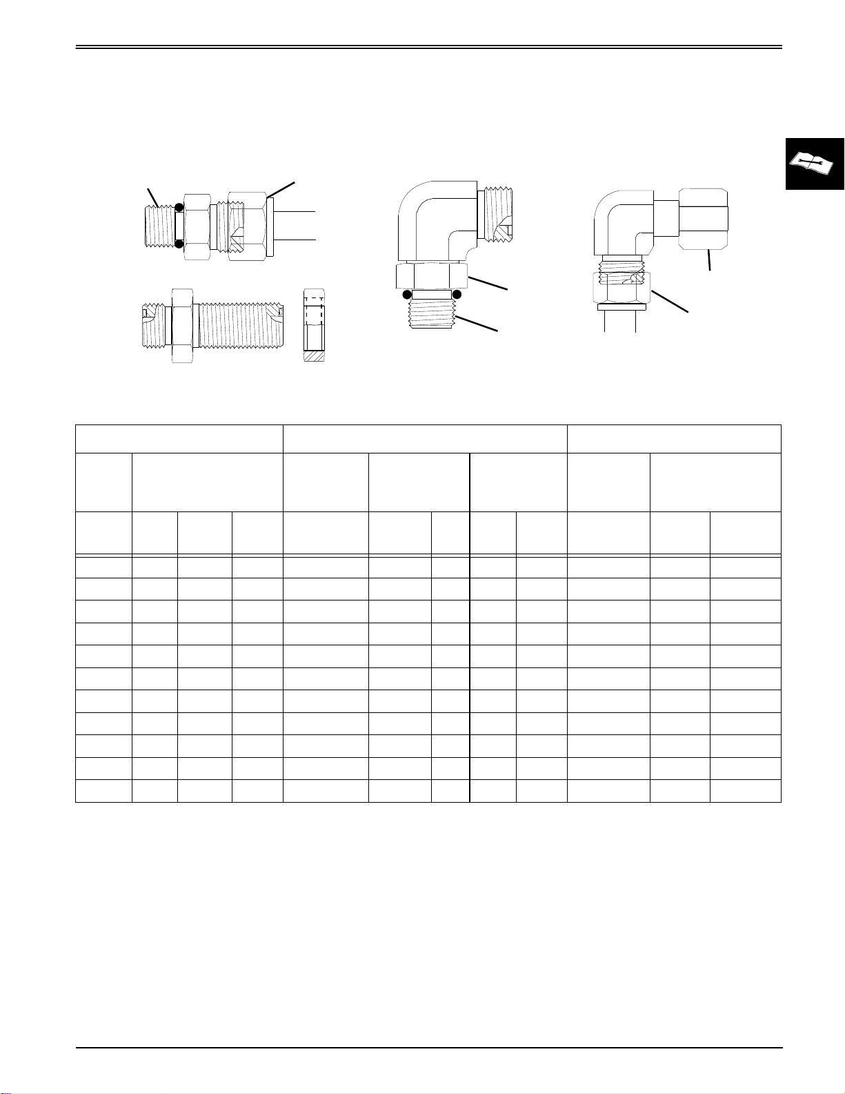
FACE SEAL FITTINGS WITH INCH STUD ENDS TORQUE
Stud End
Stud Straight and Tube Nut
Bulkhead Union and Bulkhead Lucknut
Nominal Tube O.D./Hose I.D. Face Seal Tube/Hose End O-ring Stud Ends
Metric
Tube
O.D.
Inch Tube O.D. Thread Size
Tube Nut
Locknut
Stud End
90 Adjustable Stud Elbow
Tube Nut/
Swivel Nut
Torque
Bulkhead
Locknut
Torque
Swivel Nut
Tube Nut
90 Swivel Elbow and Tube Nut
Thread
Size
Straight Fitting or
Locknut Torque
mm
10 -6 0.375 9.52 11/16-16 24 18 24 18 9/16-18 24 18
12 -8 0.500 12.70 13/16-16 50 37 46 34 3/4-16 46 34
16 -10 0.625 15.88 1-14 69 51 62 46 7/8-14 62 46
22 -14 0.875 22.22 1-3/16-12 102 75 102 75 1-3/16-12 122 90
25 -16 1.000 25.40 1-7/16-12 142 105 142 105 1-5/16-12 142 105
32 -20 1.25 31.75 1-11/16-12 190 140 190 140 1-5/8-12 190 140
38 -24 1.50 38.10 2-12 217 160 217 160 1-7/8-12 217 160
Dash
Size
-3 0.188 4.76 3/8-24 8 6
6 -4 0.250 6.35 9/16-18 16 12 12 9 7/16-20 12 9
8 -5 0.312 7.94 1/2-20 16 12
-12 0.750 19.05 1-3/16-12 102 75 102 75 1-1/16-12 102 75
in. mm in. N•m lb-ft N•m lb-ft in. N•m lb-ft
NOTE: Torque tolerance is + 15 minus 20%.
3/20/97
2 - 9
Page 18
O-RING SEAL SERVICE RECOMMENDATIONS
SPECIFICATIONS AND INFORMATION
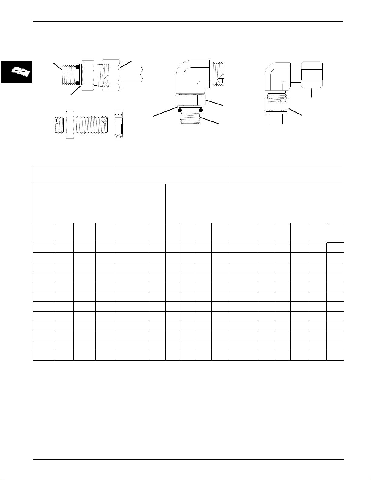
FACE SEAL FITTINGS WITH METRIC STUD ENDS TORQUE
Stud End
Groove For Metric
Stud Straight and Tube Nut
Bulkhead Union and Bulkhead Lucknut
Identification
Nominal Tube O.D./Hose
I.D.
Metric
Tube
Inch Tube O.D.
O.D.
Dash
mm
Size
in. mm in. mm N•m lb-ft N•m lb-ft mm mm N•m lb-ft N•m lb-ft
Tube Nut
Groove For Metric
Identification
90 Adjustable Stud Elbow
Face Seal Tube/Hose End
Tube
Thread
Size
Hex
Size
Nut/
Swivel
Nut
Torque
Stud End
Bulkhead
Locknut
Torque
Locknut
90 Swivel Elbow and Tube Nut
Swivel Nut
Tube Nut
O-ring Stud Ends, Straight Fitting or
Locknut
Thread
Size
Hex
Size
Steel or
Gray Iron
Torque
Aluminum
Torque
6 -4 0.250 6.35 9/16-18 17 16 12 12 9 M12X1.5 17 21 15.5 9 6.6
8 -5 0.312 7.94
M14X1.5 19 33 24 15 11
10 -6 0.375 9.52 11/16-16 22 24 18 24 18 M16X1.5 22 41 30 18 13
12 -8 0.500 12.70 13/16-16 24 50 37 46 34 M18X1.5 24 50 37 21 15
16 -10 0.625 15.88 1-14 30 69 51 62 46 M22X1.5 27 69 51 28 21
-12 0.750 19.05 1-3/16-12 36 102 75 102 75 M27X2 32 102 75 46 34
22 -14 0.875 22.22 1-3/16-12 36 102 75 102 75 M30X2 36
25 -16 1.000 25.40 1-7/16-12 41 142 105 142 105 M33X2 41 158 116 71 52
28 M38X2 46 176 130 79 58
32 -20 1.25 31.75 1-11/16-12 50 190 140 190 140 M42X2 50 190 140 85 63
38 -24 1.50 38.10 2-12 60 217 160 217 160 M48X2 55 217 160 98 72
NOTE: Torque tolerance is + 15 minus 20%.
2 - 10
3/20/97
Page 19
SPECIFICATIONS AND INFORMATION
q
g
g
q
(6)
(9)
(12)
(18)
(34)
(46)
(75)
(90)
(
)
(
)
(
)
Special Nut
Special Washer
Angle Fitting
O-RING SEAL SERVICE RECOMMENDATIONS
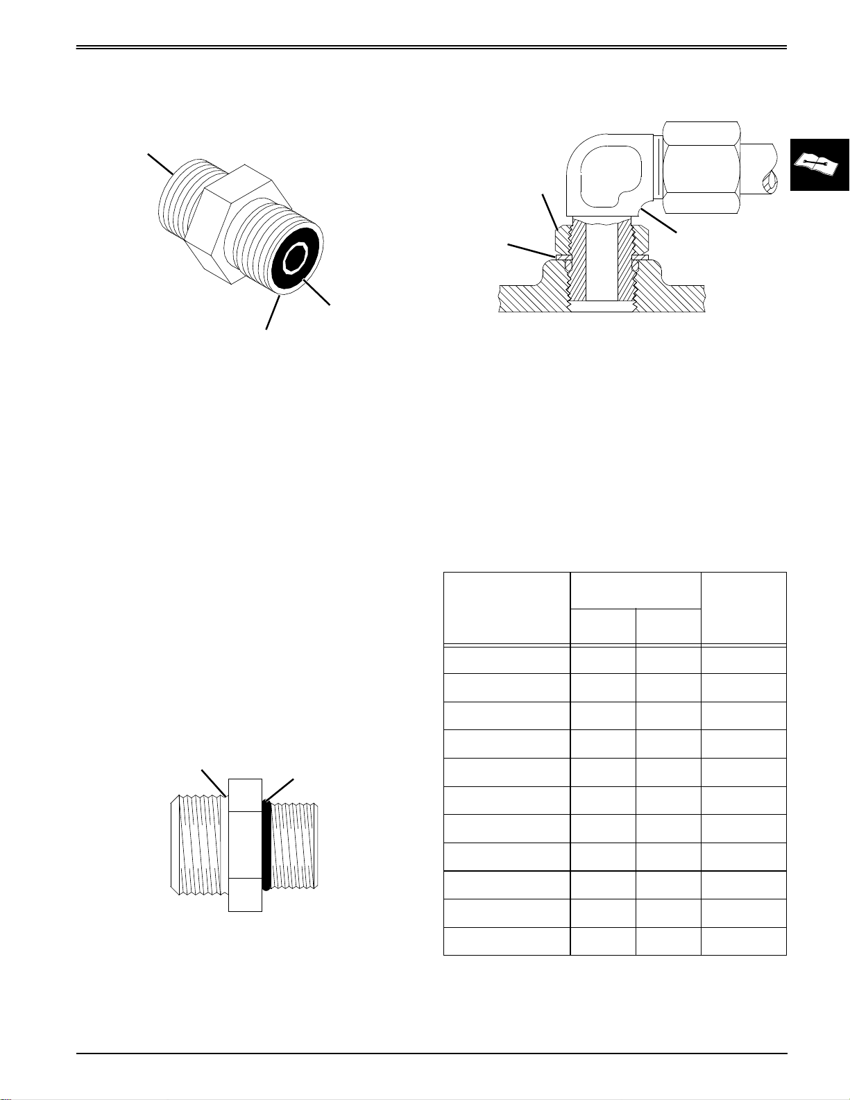
O-RING FACE SEAL FITTINGS
Sealing Surface
O-ring
Sealing Surface
1. Inspect the fitting sealing surfaces. They must be
free of dirt or defects.
2. Inspect the O-ring. It must be free of damage or
defects.
3. Lubricate O-rings and install into groove using
petroleum jelly to hold in place.
4. Push O-ring into the groove with plenty of
petroleum jelly so O-ring is not displaced during
assembly.
5. Index angle fittings and tighten by hand pressing
joint together to insure O-ring remains in place.
6. Tighten fitting or nut to torque value shown on the
chart per dash size stamped on the fitting. Do not
allow hoses to twist when tightening fittings.
.
3. For angle fittings, loosen special nut and push
special washer against threads so O-ring can be
installed into the groove of fitting.
4. Turn fitting into the boss by hand until special
washer or washer face (straight fitting) contacts
boss face and O-ring is squeezed into its seat.
5. To position angle fittings, turn the fitting counterclockwise a maximum of one turn.
6. Tighten straight fittings to torque value shown on
chart. For angle fittings, tighten the special nut to
value shown in the chart while holding body of
fitting with a wrench.
STRAIGHT FITTING OR SPECIAL NUT TORQUE
Thread
Size
Tor
N•m lb-ft
ue
a
Number
of Flats
b
O-RING BOSS FITTINGS
1. Inspect boss O-ring boss seat. It must be free of dirt
2. Put hydraulic oil or petroleum jelly on the O-ring.
and defects. If repeated leaks occur, inspect for
defects with a magnifying glass. Some raised
defects can be removed with a slip stone.
Groove
Place electrical tape over the threads to protect Oring from nicks. Slide O-ring over the tape and into
the groove of fitting. Remove tape.
O-ring
3/8-24 UNF 8
7/16-20 UNF 12
1/2-20 UNF 16
9/16-18 UNF 24
3/4-16 UNF 46
7/8-14 UNF 62
1-1/16-12 UN 102
1-3/16-12 UN 122
1-5/16-12 UN 142
1-5/8-12 UN 190
1-7/8-12 UN 217
a. Torque tolerance is ± 10 percent.
b. To be used if a tor
After ti
boss; then ti
number of flats shown.
htening fitting by hand, put a mark on nut or
hten special nut or straight fitting the
ue wrench cannot be used.
105
140
160
2
2
2
2
2
1-1/2
1
1
3/4
3/4
1/2
3/20/97
2 - 11
Page 20
GASOLINE SPECIFICATIONS
GASOLINE SPECIFICATIONS
4–CYCLE ENGINES - NORTH AMERICA
SPECIFICATIONS AND INFORMATION
c
Gasoline is HIGHLY FLAMMABLE, handle it with care.
DO NOT refuel machine while:
• indoors, always fill gas tank outdoors;
• machine is near an open flame or sparks;
• engine is running, STOP engine;
• engine is hot, allow it to cool sufficiently first;
• smoking.
Help prevent fires:
• fill gas tank to bottom of filler neck only;
• be sure fill cap is tight after fueling;
• clean up any gas spills IMMEDIATELY;
• keep machine clean and in good repair–free of excess grease, oil, debris, and faulty or damaged
parts;
• any storage of machines with gas left in tank should be in an area that is well ventilated to prevent
possible igniting of fumes by an open flame or spark, this includes any appliance with a pilot light.
To prevent fire or explosion caused by STATIC ELECTRIC DISCHARGE during fueling:
• ONLY use a clean, approved POLYETHYLENE PLASTIC fuel container and funnel WITHOUT any metal
screen or filter.
CAUTION
STOP ENGINE
NO OPEN FLAME
OR SPARK
NO HOT ENGINE
NO SMOKING
NO STATIC ELECTRIC
DISCHARGE
To avoid engine damage:
• DO NOT mix oil with gasoline;
•
ONLY use clean, fresh unleaded gasoline with
an octane rating (anti-knock index) of 87 or
higher
• fill gas tank at the end of each day's operation to
help prevent condensation from forming inside a
partially filled tank;
• keep up with specified service intervals.
Use of alternative oxygenated, gasohol blended,
unleaded gasoline is acceptable as long as:
• the ethyl or grain alcohol blends DO NOT exceed
10% by volume or
• methyl tertiary butyl ether (MTBE) blends DO NOT
exceed 15% by volume.
IMPORTANT: DO NOT use METHANOL gasolines
because METHANOL is harmful to the
environment and to your health.
;
c
California Proposition 65 Warning: Gasoline
engine exhaust from this product contains
chemicals known to the State of California to
cause cancer, birth defects, or other
reproductive harm.
WARNING
GASOLINE STORAGE
IMPORTANT: Keep all dirt, scale, water or other
foreign material out of gasoline.
Keep gasoline stored in a safe, protected area. Storage
of gasoline in a clean, properly marked
GASOLINE”) POLYETHYLENE PLASTIC container
WITHOUT
DO NOT
gasoline or depend on fuel filters to remove water from
gasoline. Use a water separator installed in the storage
tank outlet.
contaminated gasoline. When storing unit or gasoline,
it is recommended that you add
Conditioner and Stabilizer (TY15977)
equivalent to the gasoline.
directions on container and to properly discard empty
container.
any metal screen or filter is recommended.
use de-icers to attempt to remove water from
BE SURE
to properly discard unstable or
John Deere Gasoline
BE SURE
(“UNLEADED
or an
to follow
2 - 12
3/20/97
Page 21
SPECIFICATIONS AND INFORMATION
4–CYCLE ENGINES - EUROPE
GASOLINE SPECIFICATIONS
c
Gasoline is HIGHLY FLAMMABLE, handle it with care.
DO NOT refuel machine while:
• indoors, always fill gas tank outdoors;
• machine is near an open flame or sparks;
• engine is running, STOP engine;
• engine is hot, allow it to cool sufficiently first;
• smoking.
Help prevent fires:
• fill gas tank to bottom of filler neck only;
• be sure fill cap is tight after fueling;
• clean up any gas spills IMMEDIATELY;
• keep machine clean and in good repair–free of excess grease, oil, debris, and faulty or damaged
parts;
• any storage of machines with gas left in tank should be in an area that is well ventilated to prevent
possible igniting of fumes by an open flame or spark, this includes any appliance with a pilot light.
To prevent fire or explosion caused by STATIC ELECTRIC DISCHARGE during fueling:
• ONLY use a clean, approved POLYETHYLENE PLASTIC fuel container and funnel WITHOUT any metal
screen or filter.
CAUTION
STOP ENGINE
NO OPEN FLAME
OR SPARK
NO HOT ENGINE
NO SMOKING
NO STATIC ELECTRIC
DISCHARGE
To avoid engine damage:
• DO NOT mix oil with gasoline;
•
ONLY use clean, fresh unleaded gasoline with
an octane rating (anti-knock index) of 87 or
higher
• fill gas tank at the end of each day's operation to
help prevent condensation from forming inside a
partially filled tank;
• keep up with specified service intervals.
Use of alternative oxygenated, gasohol blended,
unleaded gasoline is acceptable as long as:
• the ethyl or grain alcohol blends DO NOT exceed
10% by volume or
• methyl tertiary butyl ether (MTBE) blends DO NOT
exceed 15% by volume.
IMPORTANT: DO NOT use METHANOL gasolines
because METHANOL is harmful to the
environment and to your health.
;
GASOLINE STORAGE
IMPORTANT: Keep all dirt, scale, water or other
foreign material out of gasoline.
Keep gasoline stored in a safe, protected area. Storage
of gasoline in a clean, properly marked
GASOLINE”) POLYETHYLENE PLASTIC container
WITHOUT
DO NOT
gasoline or depend on fuel filters to remove water from
gasoline. Use a water separator installed in the storage
tank outlet.
contaminated gasoline. When storing unit or gasoline,
it is recommended that you add
Conditioner and Stabilizer (TY15977)
equivalent to the gasoline.
directions on container and to properly discard empty
container.
any metal screen or filter is recommended.
use de-icers to attempt to remove water from
BE SURE
to properly discard unstable or
John Deere Gasoline
BE SURE
(“UNLEADED
or an
to follow
3/20/97
2 - 13
Page 22
4–CYCLE GASOLINE ENGINE OIL
4–CYCLE GASOLINE ENGINE OIL
4–CYCLE GASOLINE ENGINE OIL NORTH AMERICA
IMPORTANT: Kohler command engines were
designed and built to use multi-viscosity oil.
Multi-viscosity oil is required for proper
operation of hydraulic valve lifters used in
Kohler command engines.
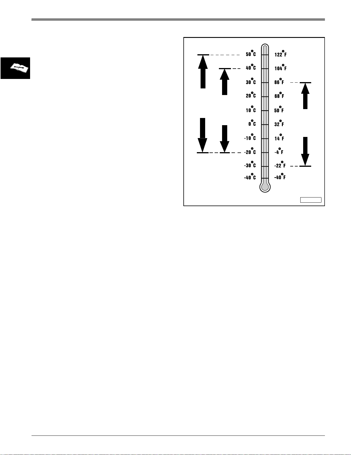
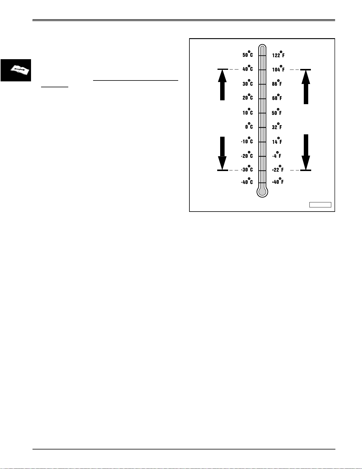
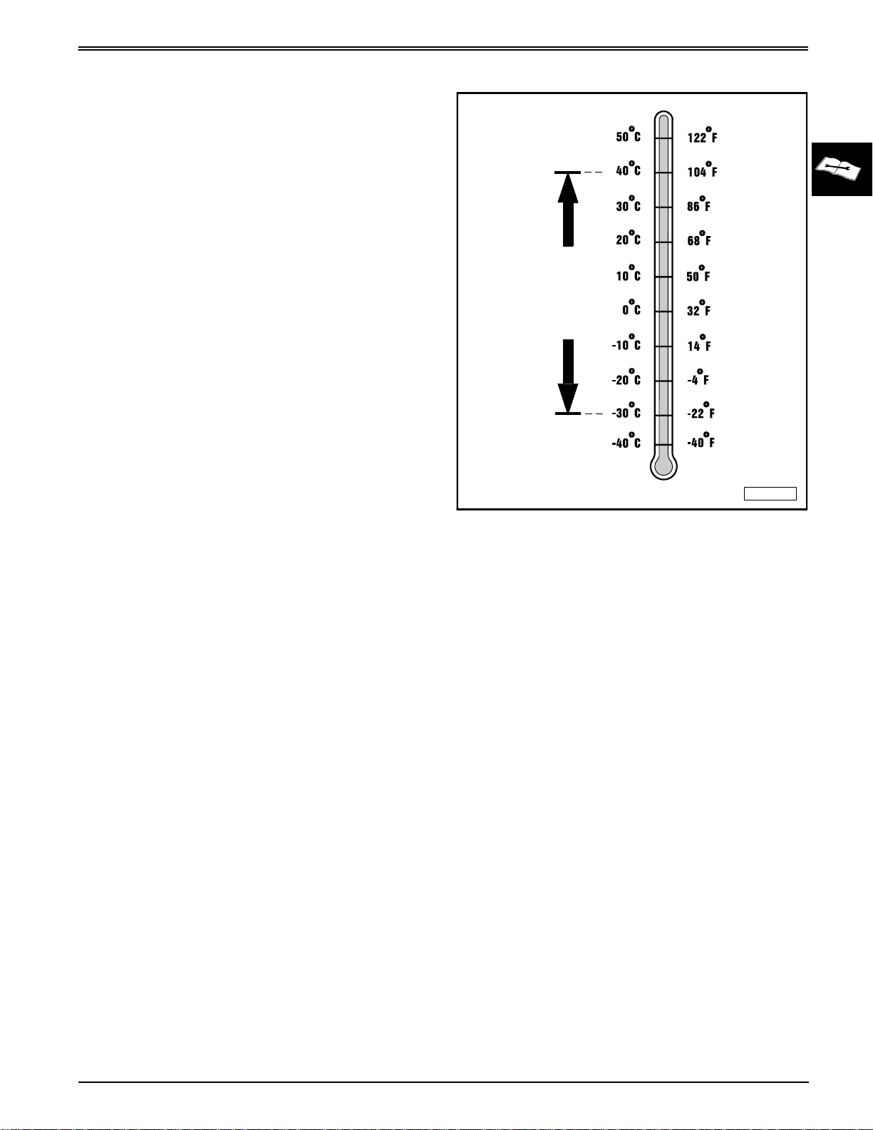
Use the appropriate oil viscosity based on the expected
air temperature range during the period between
recommended oil changes. Operating outside of these
recommended oil air temperature ranges may cause
premature engine failure.
SPECIFICATIONS AND INFORMATION
SAE 10W-40
SAE 10W-30
SAE 5W-30
The following John Deere oils are
•
PLUS–4®—SAE 10W-40;
•
TURF–GARD®—SAE 10W-30;
•
PLUS–4®—SAE 10W-30
The following John Deere oil is
based on their specified temperature range:
•
TORQ–GARD SUPREME®—SAE 5W-30
Other oils may be used if above John Deere oils are
not available, provided they meet one of the following
specifications:
• SAE 10W-40—API Service Classification SG or
higher;
• SAE 10W-30—API Service Classification SG or
higher;
• SAE 5W-30—API Service Classification SG or
higher.
PREFERRED
;
also recommended
:
.
PREFERRED
,
John Deere Dealers:
reference the following publications to recommend the
proper oil for your customers:
• Module DX,ENOIL2 in JDS–G135;
• Section 530, Lubricants & Hydraulics, of the John
Deere Merchandise Sales Guide;
• Lubrication Sales Manual PI7032.
AIR TEMPERATURE
You may want to cross-
M58275
2 - 14
3/20/97
Page 23
SPECIFICATIONS AND INFORMATION
4–CYCLE GASOLINE ENGINE OIL EUROPE
IMPORTANT: Kohler command engines were
designed and built to use multi-viscosity oil.
Multi-viscosity oil is required for proper
operation of hydraulic valve lifters used in
Kohler command engines.
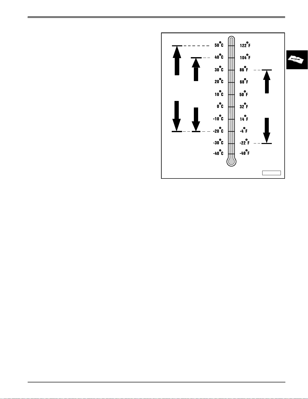
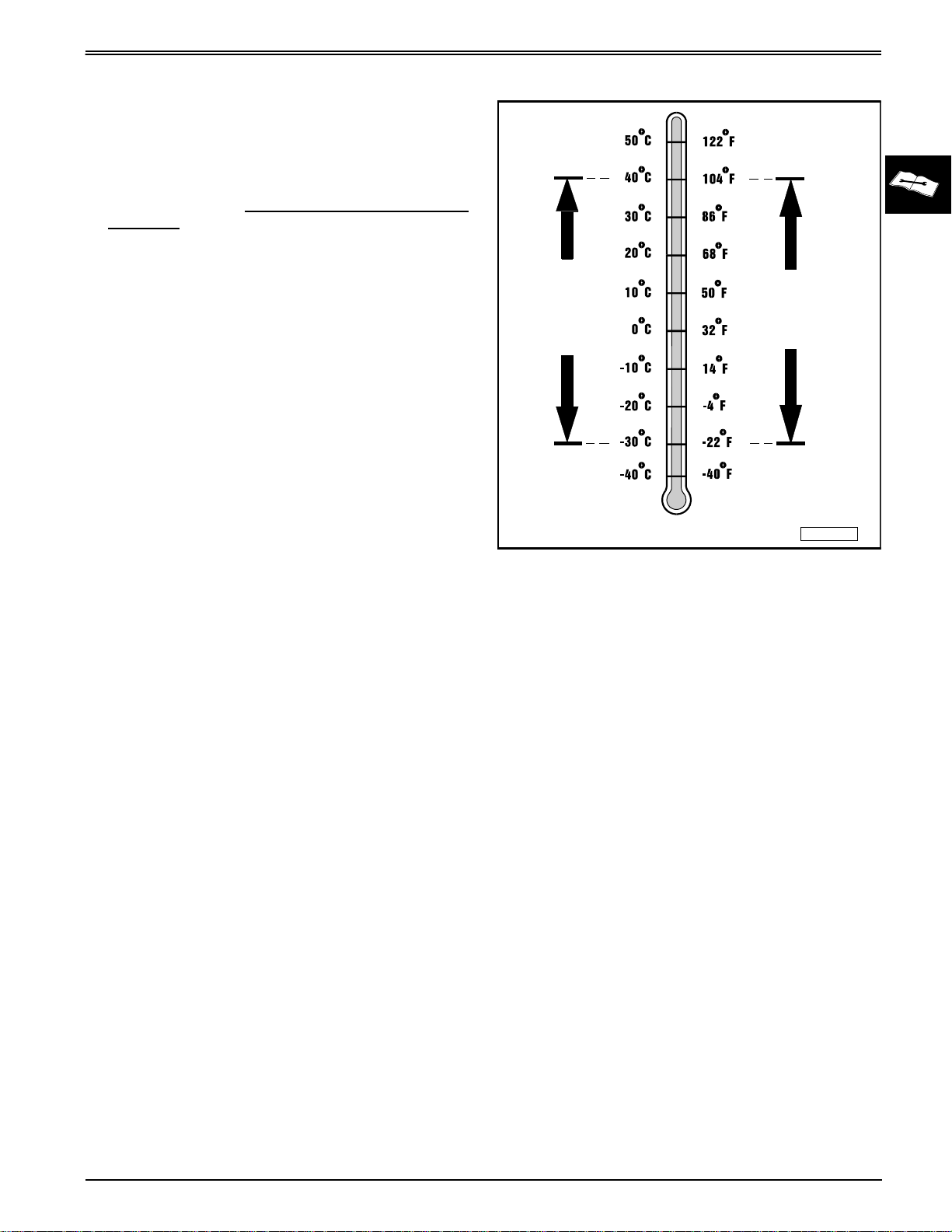
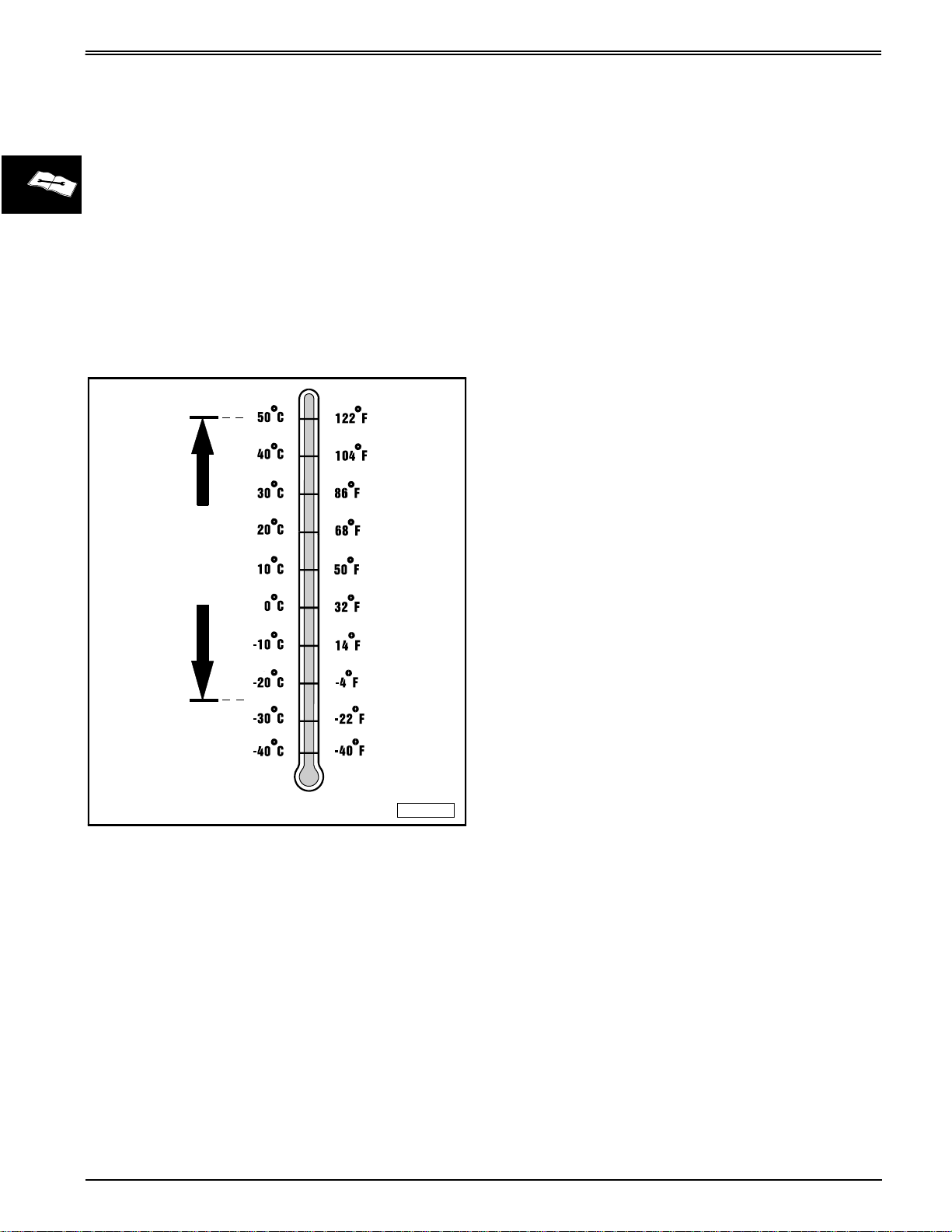
Use the appropriate oil viscosity based on the expected
air temperature range during the period between
recommended oil changes. Operating outside of these
recommended oil air temperature ranges may cause
premature engine failure.
4–CYCLE GASOLINE ENGINE OIL
SAE 10W-40
SAE 10W-30
SAE 5W-30
The following John Deere oils are
• TORQ–GARD SUPREME®—SAE 10W-40;
• UNI–GARD™—SAE 10W-40;
• TORQ–GARD SUPREME®—SAE 10W-30;
• UNI–GARD™—SAE 10W-30.
The following John Deere oil is
based on their specified temperature range:
• TORQ–GARD SUPREME®—SAE 5W-30;
• UNI–GARD™—SAE 5W-30.
Other oils may be used if above John Deere oils are
not available, provided they meet one of the following
specifications:
• CCMC Specification G4 or higher.
PREFERRED
also recommended
:
PREFERRED
,
John Deere Dealers:
reference the following publications to recommend the
proper oil for your customers:
• Module DX,ENOIL2 in JDS–G135;
• Section 530, Lubricants & Hydraulics, of the John
Deere Merchandise Sales Guide.
AIR TEMPERATURE
You may want to cross-
M58275
3/20/97
2 - 15
Page 24
4–CYCLE GASOLINE ENGINE OIL
BREAK–IN 4-CYCLE GASOLINE
ENGINE OIL - NORTH AMERICA
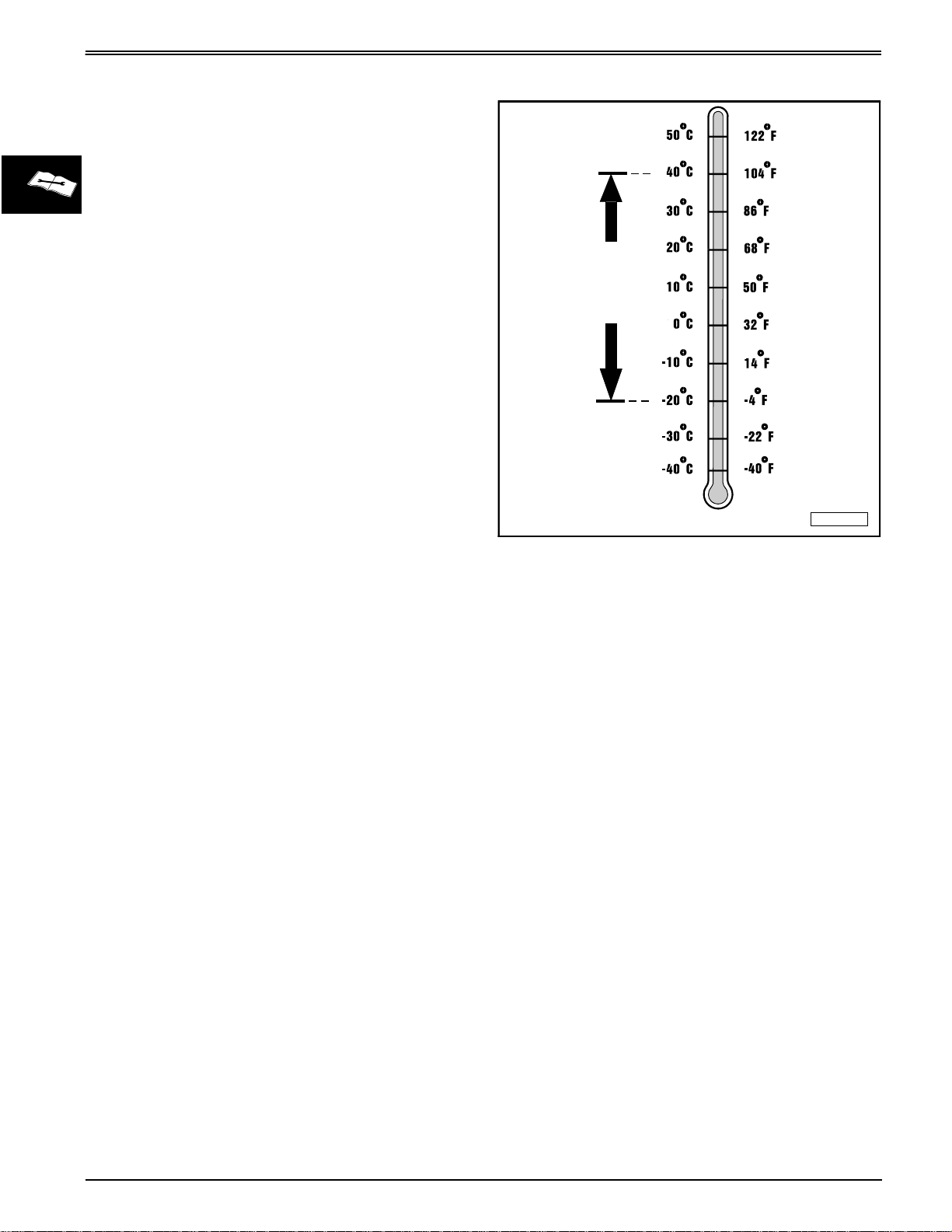
IMPORTANT: ONLY use a quality break-in oil
(multi-viscosity) in rebuilt or remanufactured
engines for the first 5 hours (maximum) of
operation. DO NOT use oils with heavier
viscosity weights than SAE 5W-30 or oils
meeting specifications API SG or SH, these oils
will not allow rebuilt or remanufactured engines
to break-in properly.
SPECIFICATIONS AND INFORMATION
The following John Deere oil is
•
BREAK–IN ENGINE OIL
John Deere BREAK–IN ENGINE OIL
with special additives for aluminum and cast iron type
engines to allow the power cylinder components
(pistons, rings, and liners as well) to “wear-in” while
protecting other engine components, valve train and
gears, from abnormal wear. Engine rebuild instructions
should be followed closely to determine if special
requirements are necessary.
John Deere BREAK–IN ENGINE OIL
recommended for non-John Deere engines, both
aluminum and cast iron types.
The following John Deere oil is
a break-in engine oil:
•
TORQ–GARD SUPREME®—SAE 5W-30.
If the above recommended John Deere oils are not
available, use a break-in engine oil meeting the
following specification during the first 5 hours
(maximum) of operation:
• SAE 5W-30—API Service Classification SE or
higher.
PREFERRED
.
also recommended
:
is formulated
is also
as
BREAK-IN OIL
PREFERRED
AIR TEMPERATURE
John Deere Dealers:
reference the following publications to recommend the
proper oil for your customers:
• Module DX,ENOIL4 in JDS–G135;
• Section 530, Lubricants & Hydraulics, of the John
Deere Merchandise Sales Guide;
• Lubrication Sales Manual PI7032.
You may want to cross-
SAE 5W-30
M58275
IMPORTANT: After the break-in period, use the
John Deere oil that is recommended for this
engine.
2 - 16
3/20/97
Page 25
SPECIFICATIONS AND INFORMATION
BREAK–IN 4-CYCLE GASOLINE
ENGINE OIL - EUROPE
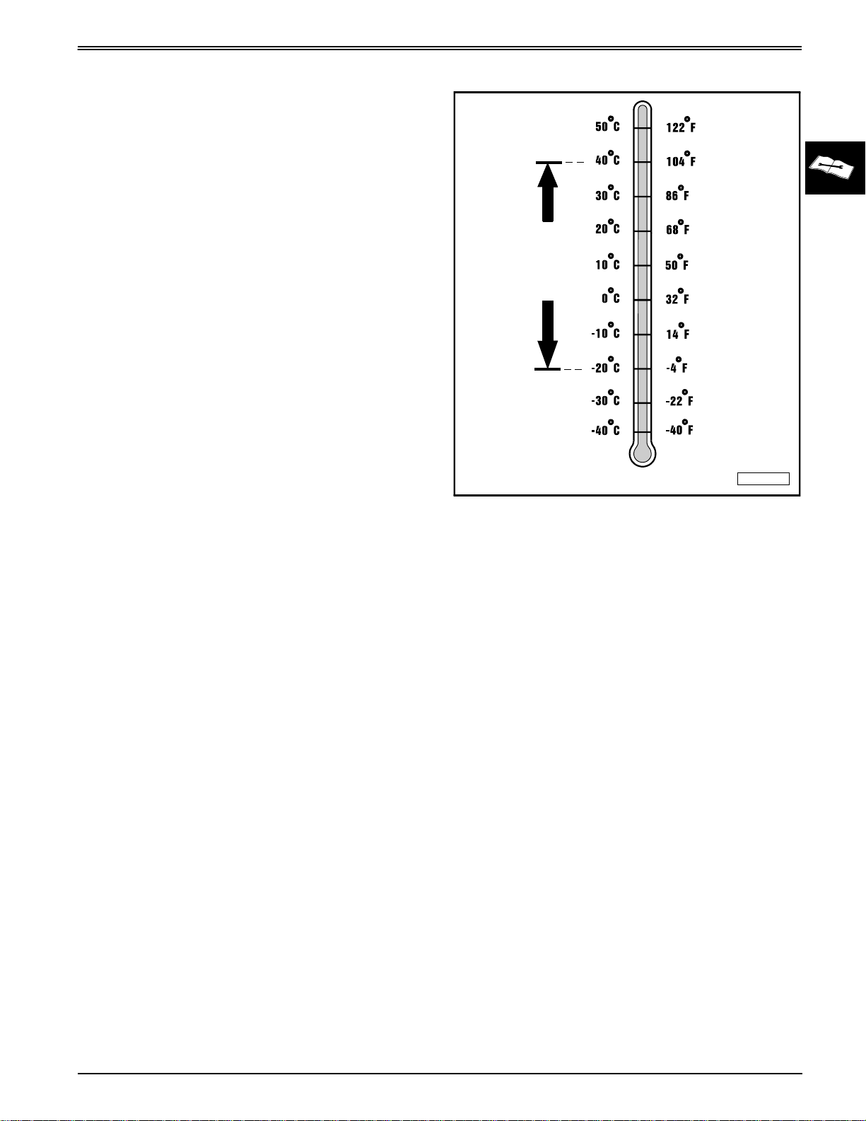
IMPORTANT: ONLY use a quality break-in oil
(multi-viscosity) in rebuilt or remanufactured
engines for the first 5 hours (maximum) of
operation. DO NOT use oils with heavier
viscosity weights than SAE 5W-30 or oils
meeting CCMC Specification G5—these oils will
not allow rebuilt or remanufactured engines to
break-in properly.
4–CYCLE GASOLINE ENGINE OIL
The following John Deere oil is
•
BREAK–IN ENGINE OIL
John Deere
with special additives for aluminum and cast iron type
engines to allow the power cylinder components
(pistons, rings, and liners as well) to “wear-in” while
protecting other engine components, valve train and
gears, from abnormal wear. Engine rebuild instructions
should be followed closely to determine if special
requirements are necessary.
John Deere
recommended for non-John Deere engines, both
aluminum and cast iron types.
The following John Deere oil is
a break-in engine oil:
•
TORQ–GARD SUPREME®—SAE 5W-30.
If the above recommended John Deere oils are not
available, use a break-in engine oil meeting the
following specification during the first 5 hours
(maximum) of operation:
• SAE 5W-30—CCMC Specification G4 or higher.
BREAK–IN ENGINE OIL
BREAK–IN ENGINE OIL
PREFERRED
.
also recommended
:
is formulated
is also
as
BREAK-IN OIL
PREFERRED
AIR TEMPERATURE
John Deere Dealers:
reference the following publications to recommend the
proper oil for your customers:
• Module DX,ENOIL4 in JDS–G135;
• Section 530, Lubricants & Hydraulics, of the John
Deere Merchandise Sales Guide.
You may want to cross-
SAE 5W-30
M58275
IMPORTANT: After the break-in period, use the
John Deere oil that is specified for this engine.
3/20/97
2 - 17
Page 26
HYDROSTATIC TRANSMISSION OIL
HYDROSTATIC TRANSMISSION OIL
HYDROSTATIC TRANSMISSION OIL
- NORTH AMERICA
Use the following oil viscosity based on the air
temperature range. Operating outside of the
recommended oil air temperature range may cause
premature hydrostatic transmission failure.
SPECIFICATIONS AND INFORMATION
IMPORTANT: ONLY use a quality SAE 10W-30
engine oil in this transmission. DO NOT mix any
other oils in this transmission. DO NOT use
BIO–HY–GARD® in this transmission.
The following John Deere oils are
•
TURF-GARD®—SAE 10W-30;
•
PLUS-4®—SAE 10W-30.
Other oils may be used if above recommended John
Deere oils are not available, provided they meet one of
the following specifications:
• API Service Classification SG or higher.
PREFERRED
:
SAE 10W-30
AIR TEMPERATURE
John Deere Dealers:
reference the following publications to recommend the
proper oil for your customers:
• Module DX,ENOIL2 in JDS–G135;
• Section 530, Lubricants & Hydraulics, of the John
Deere Merchandise Sales Guide;
• Lubrication Sales Manual PI7032.
You may want to cross-
M58275
2 - 18
3/20/97
Page 27
SPECIFICATIONS AND INFORMATION
M58275
AIR TEMPERATURE
SAE 10W-30
HYDROSTATIC TRANSMISSION OIL
- EUROPE
Use the following oil viscosity based on the air
temperature range. Operating outside of the
recommended oil air temperature range may cause
premature hydrostatic transmission failure.
IMPORTANT: ONLY use a quality SAE 10W-30
engine oil in this transmission. DO NOT mix any
other oils in this transmission. DO NOT use
BIO–HY–GARD® in this transmission.
HYDROSTATIC TRANSMISSION OIL
The following John Deere oil is
•
TORQ-GARD SUPREME®—SAE 10W-30.
Other oils may be used if above recommended John
Deere oils are not available, provided they meet one of
the following specifications:
• CCMC Specification G4 or higher.
PREFERRED
:
John Deere Dealers:
reference the following publications to recommend the
proper oil for your customers:
• Module DX,ENOIL2 in JDS–G135;
• Section 530, Lubricants & Hydraulics, of the John
Deere Merchandise Sales Guide.
You may want to cross-
3/20/97
2 - 19
Page 28

ALTERNATIVE LUBRICANTS
SPECIFICATIONS AND INFORMATION
ALTERNATIVE LUBRICANTS
Conditions in certain geographical areas outside the
United States and Canada may require different
lubricant recommendations than the ones printed in
this technical manual or the operator's manual. Consult
with your John Deere Dealer, or Sales Branch, to
obtain the alternative lubricant recommendations.
IMPORTANT: Use of alternative lubricants could
cause reduced life of the component.
If alternative lubricants are to be used, it is
recommended that the factory fill be thoroughly
removed before switching to any alternative lubricant.
SYNTHETIC LUBRICANTS
Synthetic lubricants may be used in John Deere
equipment if they meet the applicable performance
requirements (industry classification and/or military
specification) as shown in this manual.
The recommended air temperature limits and service
or lubricant change intervals should be maintained as
shown in the operator’s manual.
Avoid mixing different brands, grades, or types of oil.
Oil manufacturers blend additives in their oils to meet
certain specifications and performance requirements.
Mixing different oils can interfere with the proper
functioning of these additives and degrade lubricant
performance.
LUBRICANT STORAGE
All machines operate at top efficiency only when clean
lubricants are used. Use clean storage containers to
handle all lubricants. Store them in an area protected
from dust, moisture, and other contamination. Store
drums on their sides. Make sure all containers are
properly marked as to their contents. Dispose of all old,
used containers and their contents properly.
MIXING OF LUBRICANTS
In general, avoid mixing different brands or types of
lubricants. Manufacturers blend additives in their
lubricants to meet certain specifications and
performance requirements. Mixing different lubricants
can interfere with the proper functioning of these
additives and lubricant properties which will downgrade
their intended specified performance.
OIL FILTERS
IMPORTANT: Filtration of oils is critical to proper
lubrication performance. Always change filters
regularly.
The following John Deere oil filters are PREFERRED:
• AUTOMOTIVE AND LIGHT TRUCK ENGINE OIL
FILTERS.
Most John Deere filters contain pressure relief and
anti-drainback valves for better engine protection.
Other oil filters may be used if above recommended
John Deere oil filters are not available, provided they
meet the following specification:
• ASTB Tested In Accordance With SAE J806.
John Deere Dealers:
reference the following publications to recommend the
proper oil filter for your customers:
• Module DX,FILT in JDS–G135;
• Section 540, Lubricants & Hydraulics, of the John
Deere Merchandise Sales Guide;
• Lawn & Grounds Care Tune-Up Guide PI672.
You may want to cross-
2 - 20
3/20/97
Page 29
SPECIFICATIONS AND INFORMATION
GEAR TRANSMISSION GREASE
Use the following gear grease based on the air
temperature range. Operating outside of the
recommended grease air temperature range may
cause premature gear transmission failure.
IMPORTANT: ONLY use these specified greases in
this transmission. DO NOT mix any other
greases in this transmission. DO NOT use any
BIO–GREASE in this transmission.
GEAR TRANSMISSION GREASE
use the following
ONLY
PREFERRED
input shaft needle bearing
lubricant:
grease as the
• Unirex N3 Grease®—M120263.
Other greases may be used as the input shaft needle
bearing lubricant if they meet or exceed the following
specification:
• ASTM D–1743, NLGI Grade 1.
use the following
ONLY
gear housing
PREFERRED
lubricant:
grease as the
• Shell Darina D Grease®—AM119608.
Other greases may be used as the gear housing
lubricant if they meet or exceed the following
specification:
• ASTM D–1743, NLGI Grade 1.
ASTM D–1743
NLGI Grade 1
AIR TEMPERATURE
John Deere Dealers:
You may want to cross-
M58275
reference the following publications to recommend the
proper grease for your customers:
• Module DX,GREA1 in JDS–G135;
• Section 530, Lubricants & Hydraulics, of the John
Deere Merchandise Sales Guide;
• Lubrication Sales Manual PI7032.
3/20/97
2 - 21
Page 30
ANTI-CORROSION GREASE SPECIFICATIONS
ANTI-CORROSION GREASE
SPECIFICATIONS
This anti-corrosion grease is formulated to provide the
best protection against absorbing moisture, which is
one of the major causes of corrosion. This grease is
also superior in its resistance to separation and
migration.
The following anti-corrosion grease is
• DuBois MPG-2® Multi-Purpose Polymer
Grease—M79292.
Other greases may be used if they meet or exceed the
following specifications:
• John Deere Standard JDM J13A2, NLGI Grade 1.
PREFERRED
:
SPECIFICATIONS AND INFORMATION
JDM J13A2
NLGI Grade 1
AIR TEMPERATURE
John Deere Dealers:
reference the following publications to recommend the
proper grease for your customers:
• Module DX,GREA1 in JDS–G135;
• Section 530, Lubricants & Hydraulics, of the John
Deere Merchandise Sales Guide;
• Lubrication Sales Manual PI7032.
You may want to cross-
M58275
2 - 22
3/20/97
Page 31

SPECIFICATIONS AND INFORMATION
GREASE SPECIFICATIONS
GREASE SPECIFICATIONS
GREASE - NORTH AMERICA
Use the following grease based on the air temperature
range. Operating outside of the recommended grease
air temperature range may cause premature failures.
IMPORTANT: ONLY use a quality grease in this
application. DO NOT mix any other greases in
this application. DO NOT use any BIO–GREASE
in this application.
The following John Deere grease is
PREFERRED
• NON-CLAY HIGH-TEMPERATURE EP
GREASE®—JDM J13E4, NLGI Grade 2.
Other greases may be used if above preferred John
Deere grease is not available, provided they meet the
following specification:
• John Deere Standard JDM J13E4, NLGI Grade 2.
:
GREASE - EUROPE
Use the following grease based on the air temperature
range. Operating outside of the recommended grease
air temperature range may cause premature failures.
IMPORTANT: ONLY use a quality grease in this
application. DO NOT mix any other greases in
this application. DO NOT use any BIO–GREASE
in this application.
The following John Deere grease is
PREFERRED
• GREASE–GARD™—JDM J13E4, NLGI Grade 2.
Other greases may be used if above preferred John
Deere grease is not available, provided they meet the
following specification:
• John Deere Standard JDM J13E4, NLGI Grade 2.
:
JDM J13E4
NLGI Grade 2
AIR TEMPERATURE
John Deere Dealers:
You may want to cross-
M58275
reference the following publications to recommend the
proper grease for your customers:
• Module DX,GREA1 in JDS–G135;
• Section 530, Lubricants & Hydraulics, of the John
Deere Merchandise Sales Guide;
• Lubrication Sales Manual PI7032.
JDM J13E4
NLGI Grade 2
AIR TEMPERATURE
John Deere Dealers:
You may want to cross-
M58275
reference the following publications to recommend the
proper grease for your customers:
• Module DX,GREA1 in JDS–G135;
• Section 530, Lubricants & Hydraulics, of the John
Deere Merchandise Sales Guide.
3/20/97
2 - 23
Page 32

SERIAL NUMBER LOCATIONS
SPECIFICATIONS AND INFORMATION
SERIAL NUMBER LOCATIONS
ENGINE SERIAL NUMBER SUFFUX
Domestic Australia Export
STX38/Gear/12.5 (Steel Cam ) = 8 STX38/Gear/12.5 (Steel Cam ) = 8 STX38/Gear/12.5 (Plastic Cam ) =4
STX38/Hydro/12.5 (Steel Cam ) = 8 STX38/Hydro/12.5 (Steel Cam ) =8 STX38/Hydro/14 (Plastic Cam ) =9
STX46/Gear/14 (Plastic Cam ) = 9 STX46/Gear/14 (Plastic Cam ) = 9
STX46/Hydro/14 (Plastic Cam ) =9 STX46/Hydro/14 (Plastic Cam ) =9
IMPORTANT: When working on machines or
components that are covered by warranty, it is
IMPORTANT that you include the transporter
product identification number and the
component serial numbers on the warranty
claim form.
The location of transporter identification number and
component serial numbers are shown.
TRACTOR IDENTIFICATION
NUMBER
A
M55792
GEAR TRANSAXLE SERIAL
NUMBER
D
M55792
Gear transaxle serial number sticker (D) is on rear of
housing.
HYDROSTATIC TRANSMISSION
SERIAL NUMBER
E
Tractor identification number plate (A) is located on the
rear of frame.
ENGINE SERIAL NUMBER
C
B
M55791
Tractor engine serial number sticker (C) is located on
fan shroud and bar code sticker (B) is on air filter
housing on left side of engine.
2 - 24
M58249
Serial number (E) is stamped into top of upper case
half. It is only accessible with hydro removed.
3/20/97
Page 33

ENGINE
CONTENTS
CONTENTS
Page
ENGINE
SPECIFICATIONS. . . . . . . . . . . . . . . . . . . . . . . . . . . . . . . . . . . . . . . . . . . 3
GENERAL SPECIFICATIONS. . . . . . . . . . . . . . . . . . . . . . . . . . . . . . . . . . . . . . . . . . . 3
TEST AND ADJUSTMENT SPECIFICATIONS. . . . . . . . . . . . . . . . . . . . . . . . . . . . . . 4
REPAIR SPECIFICATIONS . . . . . . . . . . . . . . . . . . . . . . . . . . . . . . . . . . . . . . . . . . . . 4
TORQUE SPECIFICATIONS . . . . . . . . . . . . . . . . . . . . . . . . . . . . . . . . . . . . . . . . . . . 8
ESSENTIAL TOOLS . . . . . . . . . . . . . . . . . . . . . . . . . . . . . . . . . . . . . . . . . . . . . . . . . . 9
OTHER MATERIALS. . . . . . . . . . . . . . . . . . . . . . . . . . . . . . . . . . . . . . . . . . . . . . . . . . 9
SERVICE PARTS KITS. . . . . . . . . . . . . . . . . . . . . . . . . . . . . . . . . . . . . . . . . . . . . . . . 9
TROUBLESHOOTING . . . . . . . . . . . . . . . . . . . . . . . . . . . . . . . . . . . . . . 10
DIAGNOSIS. . . . . . . . . . . . . . . . . . . . . . . . . . . . . . . . . . . . . . . . . . . . . . . 14
MAIN COMPONENTS. . . . . . . . . . . . . . . . . . . . . . . . . . . . . . . . . . . . . . . . . . . . . . . . 14
ENGINE HARD TO START AND/OR ENGINE STARTER KICKS OUT. . . . . . . . . . 16
ENGINE BACKFIRES, HAS LOW POWER, WILL NOT START,
OR TURNS OVER SLOWLY AND LOCKS UP . . . . . . . . . . . . . . . . . . . . . . . . . . . 17
TESTS AND ADJUSTMENTS . . . . . . . . . . . . . . . . . . . . . . . . . . . . . . . . 18
THROTTLE CABLE ADJUSTMENT . . . . . . . . . . . . . . . . . . . . . . . . . . . . . . . . . . . . . 18
FAST IDLE SPEED ADJUSTMENT . . . . . . . . . . . . . . . . . . . . . . . . . . . . . . . . . . . . . 19
SLOW IDLE SPEED ADJUSTMENT
—NON CARB/EPA (EARLY MODELS) . . . . . . . . . . . . . . . . . . . . . . . . . . . . . . . . . 20
SLOW IDLE SPEED ADJUSTMENT
—CARB/EPA STX38 (SN 210001— ) & STX46 . . . . . . . . . . . . . . . . . . . . . . . . . 21
CYLINDER COMPRESSION TEST . . . . . . . . . . . . . . . . . . . . . . . . . . . . . . . . . . . . . 22
AUTOMATIC COMPRESSION RELEASE TEST . . . . . . . . . . . . . . . . . . . . . . . . . . . 22
CRANKCASE VACUUM TEST . . . . . . . . . . . . . . . . . . . . . . . . . . . . . . . . . . . . . . . . . 23
FUEL FLOW TEST . . . . . . . . . . . . . . . . . . . . . . . . . . . . . . . . . . . . . . . . . . . . . . . . . . 24
OIL PRESSURE TEST . . . . . . . . . . . . . . . . . . . . . . . . . . . . . . . . . . . . . . . . . . . . . . . 24
FUEL AND AIR SYSTEM REPAIR. . . . . . . . . . . . . . . . . . . . . . . . . . . . . 25
FUEL TANK AND DASH PANEL COMPONENTS . . . . . . . . . . . . . . . . . . . . . . . . . . 25
REMOVE AND INSTALL FUEL TANK AND DASH PANEL ASSEMBLY . . . . . . . . . 26
REPLACE FUEL FILTER . . . . . . . . . . . . . . . . . . . . . . . . . . . . . . . . . . . . . . . . . . . . . 28
AIR INTAKE SYSTEM COMPONENTS . . . . . . . . . . . . . . . . . . . . . . . . . . . . . . . . . . 29
REMOVE AND INSTALL CARBURETOR. . . . . . . . . . . . . . . . . . . . . . . . . . . . . . . . . 29
INSPECT CARBURETOR. . . . . . . . . . . . . . . . . . . . . . . . . . . . . . . . . . . . . . . . . . . . . 30
ENGINE REPAIR . . . . . . . . . . . . . . . . . . . . . . . . . . . . . . . . . . . . . . . . . . 31
REMOVE AND INSTALL ENGINE . . . . . . . . . . . . . . . . . . . . . . . . . . . . . . . . . . . . . . 31
REMOVE AND INSTALL ROCKER ARMS. . . . . . . . . . . . . . . . . . . . . . . . . . . . . . . . 32
INSPECT PUSH ROD. . . . . . . . . . . . . . . . . . . . . . . . . . . . . . . . . . . . . . . . . . . . . . . . 32
REMOVE AND INSTALL CYLINDER HEAD. . . . . . . . . . . . . . . . . . . . . . . . . . . . . . . 32
REMOVE AND INSTALL VALVES AND SPRINGS . . . . . . . . . . . . . . . . . . . . . . . . . 33
INSPECT CYLINDER HEAD. . . . . . . . . . . . . . . . . . . . . . . . . . . . . . . . . . . . . . . . . . . 33
INSPECT VALVES . . . . . . . . . . . . . . . . . . . . . . . . . . . . . . . . . . . . . . . . . . . . . . . . . . 33
ANALYZE VALVES . . . . . . . . . . . . . . . . . . . . . . . . . . . . . . . . . . . . . . . . . . . . . . . . . . 34
INSPECT VALVE GUIDES . . . . . . . . . . . . . . . . . . . . . . . . . . . . . . . . . . . . . . . . . . . . 35
3/20/97
3 - 1
Page 34

CONTENTS
RECONDITION VALVE SEATS . . . . . . . . . . . . . . . . . . . . . . . . . . . . . . . . . . . . . . . . 35
LAP VALVES. . . . . . . . . . . . . . . . . . . . . . . . . . . . . . . . . . . . . . . . . . . . . . . . . . . . . . . 36
INSPECT BREATHER . . . . . . . . . . . . . . . . . . . . . . . . . . . . . . . . . . . . . . . . . . . . . . . 36
REMOVE AND INSTALL FLYWHEEL . . . . . . . . . . . . . . . . . . . . . . . . . . . . . . . . . . . 36
REMOVE AND INSTALL CAMSHAFT . . . . . . . . . . . . . . . . . . . . . . . . . . . . . . . . . . . 37
INSPECT CAMSHAFT . . . . . . . . . . . . . . . . . . . . . . . . . . . . . . . . . . . . . . . . . . . . . . . 37
MEASURE CAMSHAFT END PLAY. . . . . . . . . . . . . . . . . . . . . . . . . . . . . . . . . . . . . 38
HYDRAULIC VALVE LIFTERS—REMOVE AND INSTALL . . . . . . . . . . . . . . . . . . . 38
HYDRAULIC VALVE LIFTERS—INSPECTION . . . . . . . . . . . . . . . . . . . . . . . . . . . . 38
BALANCER SHAFT REMOVAL & INSTALLATION . . . . . . . . . . . . . . . . . . . . . . . . . 39
BALANCER SHAFT INSPECTION . . . . . . . . . . . . . . . . . . . . . . . . . . . . . . . . . . . . . . 40
GOVERNOR REMOVAL & INSTALLATION. . . . . . . . . . . . . . . . . . . . . . . . . . . . . . . 40
GOVERNOR INSPECTION. . . . . . . . . . . . . . . . . . . . . . . . . . . . . . . . . . . . . . . . . . . . 41
REMOVE PISTON ASSEMBLY . . . . . . . . . . . . . . . . . . . . . . . . . . . . . . . . . . . . . . . . 41
ANALYZE PISTON RING WEAR . . . . . . . . . . . . . . . . . . . . . . . . . . . . . . . . . . . . . . . 42
ANALYZE PISTON WEAR . . . . . . . . . . . . . . . . . . . . . . . . . . . . . . . . . . . . . . . . . . . . 42
PISTON ASSEMBLY—DISASSEMBLE . . . . . . . . . . . . . . . . . . . . . . . . . . . . . . . . . . 44
PISTON INSPECTION . . . . . . . . . . . . . . . . . . . . . . . . . . . . . . . . . . . . . . . . . . . . . . . 44
PISTON RING END GAP MEASUREMENT. . . . . . . . . . . . . . . . . . . . . . . . . . . . . . . 44
PISTON RING SIDE CLEARANCE. . . . . . . . . . . . . . . . . . . . . . . . . . . . . . . . . . . . . . 44
PISTON ASSEMBLY MEASUREMENT . . . . . . . . . . . . . . . . . . . . . . . . . . . . . . . . . . 45
PISTON ASSEMBLY. . . . . . . . . . . . . . . . . . . . . . . . . . . . . . . . . . . . . . . . . . . . . . . . . 46
INSTALL PISTON ASSEMBLY. . . . . . . . . . . . . . . . . . . . . . . . . . . . . . . . . . . . . . . . . 46
INSTALL CONNECTING ROD . . . . . . . . . . . . . . . . . . . . . . . . . . . . . . . . . . . . . . . . . 47
CRANKSHAFT REMOVAL & INSTALLATION . . . . . . . . . . . . . . . . . . . . . . . . . . . . . 47
CRANKSHAFT & MAIN BEARING INSPECTION. . . . . . . . . . . . . . . . . . . . . . . . . . . 47
CRANKSHAFT ALIGNMENT . . . . . . . . . . . . . . . . . . . . . . . . . . . . . . . . . . . . . . . . . . 48
REMOVE AND INSTALL OIL PAN . . . . . . . . . . . . . . . . . . . . . . . . . . . . . . . . . . . . . . 48
REMOVE AND INSTALL OIL PAN SEAL . . . . . . . . . . . . . . . . . . . . . . . . . . . . . . . . . 49
REMOVE AND INSTALL CRANKCASE OIL SEAL . . . . . . . . . . . . . . . . . . . . . . . . . 49
INSPECT OIL PICKUP . . . . . . . . . . . . . . . . . . . . . . . . . . . . . . . . . . . . . . . . . . . . . . . 50
OIL PUMP RELIEF VALVE INSPECT ION. . . . . . . . . . . . . . . . . . . . . . . . . . . . . . . . 50
OIL PUMP INSTALLATION. . . . . . . . . . . . . . . . . . . . . . . . . . . . . . . . . . . . . . . . . . . . 50
CYLINDER BLOCK REMOVE & INSTALL . . . . . . . . . . . . . . . . . . . . . . . . . . . . . . . . 51
CYLINDER BLOCK INSPECT. . . . . . . . . . . . . . . . . . . . . . . . . . . . . . . . . . . . . . . . . . 51
CYLINDER BORE DEGLAZING . . . . . . . . . . . . . . . . . . . . . . . . . . . . . . . . . . . . . . . . 51
REBORE CYLINDER BLOCK. . . . . . . . . . . . . . . . . . . . . . . . . . . . . . . . . . . . . . . . . . 52
ENGINE
3 - 2
3/20/97
Page 35

ENGINE
SPECIFICATIONS
SPECIFICATIONS
GENERAL SPECIFICATIONS
Make . . . . . . . . . . . . . . . . . . . . . . . . . . . . . . . . . . . . . . . . . . . . . . . . . . . . . . . . . . . Kohler
Style . . . . . . . . . . . . . . . . . . . . . . . . . . . . . . . . . . . . . . . . . . . . . . . . . . . . . .Command LT
STX30 . . . . . . . . . . . . . . . . . . . . . . . . . . . . . . . . . . . . . . . . . . . . . . . . . .CV12.5—1216s
STX38 (Serial No. —270000) . . . . . . . . . . . . . . . . . . . . . . . . . . . . . . .CV12.5—1215
STX38 (Domestic & Export) (Serial No. 210001—270000) . . . . . . . . . CV12.5S—1270
STX38 (Export Gear) (Serial No. 270001—595000). . . . . . . . . . . . . . . CV12.5S—1270
STX38 (Domestic Gear & Hydro) (Serial No. 270001—595000) . . . . . . CV13S—21509
STX38 (Export Hydro) (Serial No. 240001—270000). . . . . . . . . . . . . . . . CV14S—1463
STX38 (Export Hydro) (Serial No. 270001—595000). . . . . . . . . . . . . . . . CV14S—1463
STX46 (Domestic Gear & Hydro) (Serial No. 240001—270000) . . . . . . . CV14S—1463
STX46 (Domestic Gear & Hydro) (Serial No. 270001—595000) . . . . . . CV15S—41521
STX46 (Australia Hydro) (Serial No. 270001—595000) . . . . . . . . . . . . . CV15S—41521
Type . . . . . . . . . . . . . . Gasoline, Air Cooled, Single Cylinder, 4-Cycle, Overhead Valve
Power: CV12.5—1270 . . . . . . . . . . . . . . . . . . . . . . . . . . . . . . . . . . . . 9.33 kW (12.5 hp)
CV13S—21509 . . . . . . . . . . . . . . . . . . . . . . . . . . . . . . . . . . . . 9.69 kW (13.0 hp)
CV14S—1463 . . . . . . . . . . . . . . . . . . . . . . . . . . . . . . . . . . . . . 10.5 kW (14.0 hp)
CV15S—41521 . . . . . . . . . . . . . . . . . . . . . . . . . . . . . . . . . . . 11.19 kW (15.0 hp)
Bore (12.5, 13, 14 hp). . . . . . . . . . . . . . . . . . . . . . . . . . . . . . . . . . . . . . 87 mm (3.43 in.)
Bore (15 hp) . . . . . . . . . . . . . . . . . . . . . . . . . . . . . . . . . . . . . . . . . . . . . 90 mm (3.60 in.)
Stroke (All) . . . . . . . . . . . . . . . . . . . . . . . . . . . . . . . . . . . . . . . . . . . . . . 67 mm (2.64 in.)
Displacement (12.5, 13, 14 hp). . . . . . . . . . . . . . . . . . . . . . . . . . . . . 398 cc (24.3 cu-in.)
Displacement (15 hp) . . . . . . . . . . . . . . . . . . . . . . . . . . . . . . . . . . . . 426 cc (26.0 cu-in.)
Compression Ratio . . . . . . . . . . . . . . . . . . . . . . . . . . . . . . 2:1 Cranking—8.5:1 Running
Compression Release. . . . . . . . . . . . . . . . . . . . . . . . . . . . . . . . . . Automatic/Centrifugal
Crankshaft Type . . . . . . . . . . . . . . . . . . . . . . . . . . . . . . . . . . Vertical (counterbalanced)
Lubrication. . . . . . . . . . . . . . . . . . . . . . . . . . . . . . . . . . . . . . . . Gerotor Pump (0—60 psi)
Oil Filter. . . . . . . . . . . . . . . . . . . . . . . . . . . . . . . . . . . . . .Full Flow (W/O By-Pass Valve)
Oil . . . . . . . . . . . . . . . . . . . . . . . . . . . . . . . . . . . . . . . . . . . . . . . . .John Deere Turf-Gard
Warm Climate . . . . . . . . . . . . . . . . . . . . . . . . . . . . . . . . . . . . . . . . . . . . . . . . . . . .10W30
Cold Climate . . . . . . . . . . . . . . . . . . . . . . . . . . . . . . . . . . . . . . . . . . . . . . . . . . . . . .5W30
Crankcase Capacity (with filter) . . . . . . . . . . . . . . . . . . . . . . . . . . . . . 1.8 L (1.9 U.S. qt)
Lubrication Interval . . . . . . . . . 50 Hours First Change, Every 100 Hours After or Yearly
Air Filter. . . . . . . . . . . . . . . . . . . . . . . . . . . . . . . . . . . . Paper With Outer Foam Element
Fuel Filter . . . . . . . . . . . . . . . . . . . . . . . . . . . . . . . . . . . . . . .Replaceable (In-Line Type)
Fuel Type . . . . . . . . . . . . . . . . . . . . . . . . . . . .Regular Unleaded—87 Octane Or Higher
Gasoline/Alcohol Blends. . . . . . .Up To 10% Ethyl Alcohol-90% Unleaded (By Volume)
Gasoline/Ether Blends . . . . . . . . . . . . . Up To 15% MTBE-85% Unleaded (By Volume)
Fuel Shut-Off Valve. . . . . . . . . . . . . . . . . . . . . . . . . . . . . . . .Replaceable (In-Line Type)
Fuel Shut-Off Solenoid (Optional). . . . . . . . Replaceable (Below Carburetor Float Bowl)
Weight. . . . . . . . . . . . . . . . . . . . . . . . . . . . . . . . . . . . . . . . . . . . . . . . . . 39.54 kg (87 lbs)
4/23/97
3 - 3
Page 36

SPECIFICATIONS
TEST AND ADJUSTMENT SPECIFICATIONS
Engine:
Valve Adjustment . . . . . . . . . . . . . . . . . . . . . . . . . . . . . . . . . . . . None (hydraulic lifters)
Oil Pressure (Minimum at 1250 rpm) . . . . . . . . . . . . . . . . . . . . . . . . . . 124 kPa (18 psi)
Crankcase Vacuum (Minimum At Operating Temp.) . . .25 mm (1 in.) Water Movement
Automatic Compression Release Minimum Lift (Engine Cold) . . . . . .0.25 mm (0.01 in.)
Fuel/Air System:
Carburetor Slow Idle Mixture Screw Initial Setting . . . . . . Lightly Seat, Then 1 Turn Out
Slow Idle Speed—Domestic and Export. . . . . . . . . . . . . . . . . . . . . . . . . . 1650 ±75 rpm
Fast Idle Speed—Domestic . . . . . . . . . . . . . . . . . . . . . . . . . . . . . . . . . . . 3350 ±50 rpm
Fast Idle Speed—Export. . . . . . . . . . . . . . . . . . . . . . . . . . . . . . . . . . . . . . 3000 ±50 rpm
REPAIR SPECIFICATIONS
Cylinder Head:
Cylinder Head Flatness (Maximum Warpage) . . . . . . . . . . . . . . . . 0.076 mm (0.003 in.)
Push Rod:
Maximum Bend. . . . . . . . . . . . . . . . . . . . . . . . . . . . . . . . . . . . . . . . . 0.76 mm (0.030 in.)
ENGINE
Valves and Valve Lifters:
Hydraulic Lifter Clearance. . . . . . . . . . . . . . . 0.0124—0.0501 mm (0.0005—0.0020 in.)
Intake Valve-to-Guide Clearance . . . . . . . . . . . 0.038—0.076 mm (0.0015—0.0030 in.)
Intake Valve Stem OD. . . . . . . . . . . . . . . . . . . . . . . .6.982—7.000 (0.2749—0.2756 in.)
Exhaust Valve Stem OD . . . . . . . . . . . . . . . . . . . . . . . . 6.970—6.988 (0.2744—0.2751)
Exhaust Valve-to-Guide Clearance. . . . . . . . . . 0.050—0.088 mm (0.0020—0.0035 in.)
Intake Valve Guide ID:
New. . . . . . . . . . . . . . . . . . . . . . . . . . . . . . . . 7.038—7.058 mm (0.2771—0.2779 in.)
Maximum. . . . . . . . . . . . . . . . . . . . . . . . . . . . . . . . . . . . . . . . . .7.134 mm (0.2809 in.)
Exhaust Valve Guide ID:
New. . . . . . . . . . . . . . . . . . . . . . . . . . . . . . . . 7.038—7.058 mm (0.2771—0.2779 in.)
Maximum. . . . . . . . . . . . . . . . . . . . . . . . . . . . . . . . . . . . . . . . . .7.159 mm (0.2819 in.)
Valve Guide Reamer:
Standard . . . . . . . . . . . . . . . . . . . . . . . . . . . . . . . . . . . . . . . . . . 7.048 mm (0.2775 in.)
Oversize (0.25 mm). . . . . . . . . . . . . . . . . . . . . . . . . . . . . . . . . .7.298 mm (0.2873 in.)
Intake Valve Lift (Minimum—Engine Cold) . . . . . . . . . . . . . . . . . . . .8.96 mm (0.353 in.)
Exhaust Valve Lift (Minimum—Engine Cold) . . . . . . . . . . . . . . . . . . 9.14 mm (0.360 in.)
Valve Face Angle . . . . . . . . . . . . . . . . . . . . . . . . . . . . . . . . . . . . . . . . . . . . . . . . . . . .45°
Valve Seat Angle. . . . . . . . . . . . . . . . . . . . . . . . . . . . . . . . . . . . . . . . . . . . . . . . . . . . 44.5
3 - 4
4/23/97
Page 37

ENGINE
SPECIFICATIONS
REPAIR SPECIFICATIONS (Continued)
Rocker Arms:
Rocker Arm I.D.
New. . . . . . . . . . . . . . . . . . . . . . . . . . . . . . . . . . 15.837—16.127 mm (0.63—0.64 in.)
Wear Limit. . . . . . . . . . . . . . . . . . . . . . . . . . . . . . . . . . . . . . . . .15.727 mm (0.619 in.)
Rocker Shaft:
Rocker Shaft O.D.
New. . . . . . . . . . . . . . . . . . . . . . . . . . . . . . . . . . 15.837—16.127 mm (0.63—0.64 in.)
Wear Limit. . . . . . . . . . . . . . . . . . . . . . . . . . . . . . . . . . . . . . . . .15.727 mm (0.619 in.)
Crankshaft:
End Play . . . . . . . . . . . . . . . . . . . . . . . . . . . . 0.0575—0.4925 mm (0.0023—0.0194 in.)
Crankshaft Bore (Crankcase Half) ID:
New. . . . . . . . . . . . . . . . . . . . . . . . . . . . . . 44.965—45.003 mm (1.7703—1.7718 in.)
Maximum. . . . . . . . . . . . . . . . . . . . . . . . . . . . . . . . . . . . . . . . .45.016 mm (1.7723 in.)
Clearance (New) . . . . . . . . . . . . . . . . . . . . . . . . 0.03—0.09 mm (0.0012—0.0035 in.)
Crankshaft Bore (Oil Pan Half):
New. . . . . . . . . . . . . . . . . . . . . . . . . . . . . . 44.965—45.003 mm (1.7703—1.7718 in.)
Maximum. . . . . . . . . . . . . . . . . . . . . . . . . . . . . . . . . . . . . . . . .45.016 mm (1.7723 in.)
Clearance (New) . . . . . . . . . . . . . . . . . . . . . . . . 0.03—0.09 mm (0.0012—0.0035 in.)
Main Bearing Journal OD (Flywheel End):
New. . . . . . . . . . . . . . . . . . . . . . . . . . . . . . 44.913—44.935 mm (1.7682—1.7691 in.)
Minimum . . . . . . . . . . . . . . . . . . . . . . . . . . . . . . . . . . . . . . . . . . .44.84 mm (1.765 in.)
Maximum Taper . . . . . . . . . . . . . . . . . . . . . . . . . . . . . . . . . . . . 0.022 mm (0.0009 in.)
Maximum Out-of-Round . . . . . . . . . . . . . . . . . . . . . . . . . . . . . . 0.025 mm (0.0010 in.)
Main Bearing Journal OD (Oil Pan End):
New. . . . . . . . . . . . . . . . . . . . . . . . . . . . . . 41.915—41.935 mm (1.6502—1.6510 in.)
Minimum . . . . . . . . . . . . . . . . . . . . . . . . . . . . . . . . . . . . . . . . . . .41.86 mm (1.648 in.)
Maximum Taper . . . . . . . . . . . . . . . . . . . . . . . . . . . . . . . . . . . . 0.020 mm (0.0008 in.)
Maximum Out-of-Round . . . . . . . . . . . . . . . . . . . . . . . . . . . . . . 0.025 mm (0.0010 in.)
Connecting Rod Journal OD:
New. . . . . . . . . . . . . . . . . . . . . . . . . . . . . . 38.958—38.970 mm (1.5338—1.5343 in.)
Minimum . . . . . . . . . . . . . . . . . . . . . . . . . . . . . . . . . . . . . . . . . .38.94 mm (1.5328 in.)
Maximum Taper . . . . . . . . . . . . . . . . . . . . . . . . . . . . . . . . . . . . 0.012 mm (0.0005 in.)
Maximum Out-of-Round . . . . . . . . . . . . . . . . . . . . . . . . . . . . . . 0.025 mm (0.0010 in.)
Crankshaft Total Indicated Runout (TIR):
PTO End (In Engine). . . . . . . . . . . . . . . . . . . . . . . . . . . . . . . . . . 0.15 mm (0.0059 in.)
Entire Crankshaft (In Bench V-Blocks) . . . . . . . . . . . . . . . . . . . .0.10 mm (0.0039 in.)
4/23/97
3 - 5
Page 38

SPECIFICATIONS
REPAIR SPECIFICATIONS (Continued)
Camshaft:
End Play . . . . . . . . . . . . . . . . . . . . . . . . . . . . . . . . 0.076—0.127 mm (0.003—0/005 in.)
Clearance . . . . . . . . . . . . . . . . . . . . . . . . . . . . . 0.025—0.063 mm (0.0010—0.0025 in.)
Bore ID:
New. . . . . . . . . . . . . . . . . . . . . . . . . . . . . . 20.000—20.025 mm (0.7874—0.7884 in.)
Maximum. . . . . . . . . . . . . . . . . . . . . . . . . . . . . . . . . . . . . . . . .20.038 mm (0.7889 in.)
Bearing OD:
New. . . . . . . . . . . . . . . . . . . . . . . . . . . . . . 19.962—19.975 mm (0.7859—0.7864 in.)
Minimum . . . . . . . . . . . . . . . . . . . . . . . . . . . . . . . . . . . . . . . . .19.959 mm (0.7858 in.)
Balance Shaft:
End Play . . . . . . . . . . . . . . . . . . . . . . . . . . . . 0.0575—0.3625 mm (0.0023—0.0143 in.)
Clearance . . . . . . . . . . . . . . . . . . . . . . . . . . . . . 0.025—0.063 mm (0.0009—0.0025 in.)
Bore ID:
New. . . . . . . . . . . . . . . . . . . . . . . . . . . . . . 20.000—20.025 mm (0.7874—0.7884 in.)
Maximum. . . . . . . . . . . . . . . . . . . . . . . . . . . . . . . . . . . . . . . . .20.038 mm (0.7889 in.)
Balance Shaft Bearing OD:
New. . . . . . . . . . . . . . . . . . . . . . . . . . . . . . . .19.962—19.975 mm (0.7859—7864 in.)
Minimum . . . . . . . . . . . . . . . . . . . . . . . . . . . . . . . . . . . . . . . . .19.959 mm (0.7858 in.)
ENGINE
Cylinder Bore, Piston and Rings:
Cylinder Bore ID (12.5, 13, 14 hp):
New. . . . . . . . . . . . . . . . . . . . . . . . . . . . . . 87.000—87.025 mm (3.4252—3.4262 in.)
Maximum. . . . . . . . . . . . . . . . . . . . . . . . . . . . . . . . . . . . . . . . .87.063 mm (3.4277 in.)
Cylinder Bore ID (15 hp):
New. . . . . . . . . . . . . . . . . . . . . . . . . . . . . . 90.000—90.025 mm (3.5433—3.5443 in.)
Maximum. . . . . . . . . . . . . . . . . . . . . . . . . . . . . . . . . . . . . . . . . .90.63 mm (3.5681 in.)
Maximum Out-of-Round . . . . . . . . . . . . . . . . . . . . . . . . . . . . . . . . .0.12 mm (0.0047 in.)
Maximum Taper . . . . . . . . . . . . . . . . . . . . . . . . . . . . . . . . . . . . . . . 0.05 mm (0.0020 in.)
Piston-To-Pin Clearance. . . . . . . . . . . . . . . . . . 0.006—0.017 mm (0.0002—0.0007 in.)
Piston Pin Bore ID:
New. . . . . . . . . . . . . . . . . . . . . . . . . . . . . . 19.006—19.012 mm (0.7483—0.7485 in.)
Maximum. . . . . . . . . . . . . . . . . . . . . . . . . . . . . . . . . . . . . . . . .19.025 mm (0.7490 in.)
Piston Pin OD:
New. . . . . . . . . . . . . . . . . . . . . . . . . . . . . . 18.995—19.000 mm (0.7478—0.7480 in.)
Minimum . . . . . . . . . . . . . . . . . . . . . . . . . . . . . . . . . . . . . . . .18.994 mm (0.74779 in.)
Top Compression Ring-To-Groove Side Clearance
12.5, 13, 14 hp . . . . . . . . . . . . . . . . . . . . . . . 0.040—0.105 mm (0.0016—0.0041 in.)
15 hp . . . . . . . . . . . . . . . . . . . . . . . . . . . . . . . 0.060—0.105 mm (0.0023—0.0041 in.)
Middle Compression Ring-To- Groove Side Clearance
12.5, 13, 14 hp . . . . . . . . . . . . . . . . . . . . . . . 0.040—0.072 mm (0.0016—0.0028 in.)
15 hp . . . . . . . . . . . . . . . . . . . . . . . . . . . . . . . 0.040—0.085 mm (0.0015—0.0002 in.)
Oil Control Ring-To-Groove Side Clearance
12.5, 13, 14 hp . . . . . . . . . . . . . . . . . . . . . . . 0.551—0.675 mm (0.0217—0.0266 in.)
15 hp . . . . . . . . . . . . . . . . . . . . . . . . . . . . . . . . . . .0.176—0.026 (0.0069—0.0010 in.)
Top and Center Compression Ring End Gap
New Bore:
12.5, 13, 14 hp . . . . . . . . . . . . . . . . . . . . . . . . . . . 0.3—0.5 mm (0.012—0.020 in.)
15 hp . . . . . . . . . . . . . . . . . . . . . . . . . . . . . . . . . 0.27—0.51 mm (0.010—0.020 in.)
Used Bore (Maximum)
All . . . . . . . . . . . . . . . . . . . . . . . . . . . . . . . . . . . . . . . . . . . . . . .0.77 mm (0.030 in.)
3 - 6
4/23/97
Page 39

ENGINE
REPAIR SPECIFICATIONS (Continued)
Piston Thrust Face OD:
New:
12.5, 13, 14 hp . . . . . . . . . . . . . . . . . . . . 86.941—86.959 mm (3.4229—3.4236 in.)
15 hp . . . . . . . . . . . . . . . . . . . . . . . . . . .89.951—89.969 mm (3.5413—3.5420 in.)
Minimum:
12.5, 13, 14 hp . . . . . . . . . . . . . . . . . . . . . . . . . . . . . . . . . . 86.814 mm (3.4179 in.)
15 hp . . . . . . . . . . . . . . . . . . . . . . . . . . . . . . . . . . . . . . . . . 89.824 mm (3.5363 in.)
Piston Thrust Face-To-Cylinder Bore Clearance
New:
12.5, 13, 14 hp. . . . . . . . . . . . . . . . . . . . . . . . . .0.041—0.044 mm (0.0016—0.0017 in.)
15 hp . . . . . . . . . . . . . . . . . . . . . . . . . . . . . . . . .0.031—0.043 mm (0.0012—0.0016 in.)
Connecting Rod:
Crankpin End Clearance
New . . . . . . . . . . . . . . . . . . . . . . . . . . . . . . . .0.030—0.055 mm (0.0012—0.0022 in.)
Maximum . . . . . . . . . . . . . . . . . . . . . . . . . . . . . . . . . . . . . . . . . . 0.07 mm (0.0025 in.)
Side . . . . . . . . . . . . . . . . . . . . . . . . . . . . . . . . . . . .0.18—0.41 mm (0.007—0.016 in.)
Piston Pin Clearance . . . . . . . . . . . . . . . . . . . . .0.015—0.028 mm (0.0006—0.0011 in.)
Piston Pin End ID:
New . . . . . . . . . . . . . . . . . . . . . . . . . . . . . .19.015—19.023 mm (0.7486—0.7489 in.)
Maximum . . . . . . . . . . . . . . . . . . . . . . . . . . . . . . . . . . . . . . . . 19.036 mm (0.7495 in.)
SPECIFICATIONS
Governor::
Crankcase Cross Shaft Bore ID:
New . . . . . . . . . . . . . . . . . . . . . . . . . . . . . . . .6.025—6.050 mm (0.2372—0.2382 in.)
Maximum . . . . . . . . . . . . . . . . . . . . . . . . . . . . . . . . . . . . . . . . . 6.063 mm (0.2387 in.)
Cross Shaft OD:
New . . . . . . . . . . . . . . . . . . . . . . . . . . . . . . . .5.975—6.000 mm (0.2352—0.2362 in.)
Minimum. . . . . . . . . . . . . . . . . . . . . . . . . . . . . . . . . . . . . . . . . . 5.962 mm (0.2347 in.)
Crankcase Bore-To-Cross Shaft Clearance. . . .0.025—0.075 mm (0.0010—0.0030 in.)
Gear Shaft OD:
New . . . . . . . . . . . . . . . . . . . . . . . . . . . . . . . .5.990—6.000 mm (0.2358—0.2362 in.)
Minimum. . . . . . . . . . . . . . . . . . . . . . . . . . . . . . . . . . . . . . . . . . 5.977 mm (0.2353 in.)
Gear Shaft-To- Gear Bore Clearance . . . . . . . .0.015—0.140 mm (0.0006—0.0055 in.)
4/23/97
3 - 7
Page 40

SPECIFICATIONS
TORQUE SPECIFICATIONS
(Alphabetical Order)
Air Cleaner Base Nut . . . . . . . . . . . . . . . . . . . . . . . . . . . . . . . . . . . . . 9.9 N•m (88 lb-in.)
Cylinder Head Cap Screw . . . . . . . . . . . . . . . . . . . . . . . . . . . . . . . . . . 41 N•m (30 lb-ft.)
Connecting Rod Cap Screws:
8mm Straight Shank Bolt . . . . . . . . . . . . . . . . . . . . . . . . . . . . . . 22.6 N•m (200 lb-in.)
Step Down Shank Bolt . . . . . . . . . . . . . . . . . . . . . . . . . . . . . . . . 14.6 N•m (130 lb-in.)
6mm Straight Shank Bolt . . . . . . . . . . . . . . . . . . . . . . . . . . . . . . 11.3 N•m (100 lb-in.)
Engine Mounting Cap Screws . . . . . . . . . . . . . . . . . . 27.1—46.2 N•m (240—408 lb-in.)
Fan Cap Screw . . . . . . . . . . . . . . . . . . . . . . . . . . . . . . . . . . . . . . . . . . 9.9 N•m (88 lb-in)
Flywheel Cap Screw . . . . . . . . . . . . . . . . . . . . . . . . . . . . . . . . . . . . . . . 68 N•m (50 lb-ft)
Fuel Pump/Cover Screw
New Installation (Thread Forming). . . . . . . . . . . . . . . . . . . . . . . . . 9.0 N•m (85 lb-in.)
Replacement . . . . . . . . . . . . . . . . . . . . . . . . . . . . . . . . . . . . . . . . . 7.3 N•m (65 lb-in.)
Fuel Bowl Nut. . . . . . . . . . . . . . . . . . . . . . . . . . . . . . . . . . . . . . . . . . . 4.0 N•m (35 lb-in.)
Governor Control Panel Screw . . . . . . . . . . . . . . . . . . . . . . . . . . . . . 9.9 N•m (88 lb-in.)
Ignition Module Screw
New Installation (Thread Forming). . . . . . . . . . . . . . . . . . . . . . . . . 6.2 N•m (55 lb-in.)
Replacement . . . . . . . . . . . . . . . . . . . . . . . . . . . . . . . . . . . . . . . . . 4.0 N•m (35 lb-in.)
Muffler Nut . . . . . . . . . . . . . . . . . . . . . . . . . . . . . . . . . . . . . . . . . . . 24.4 N•m (216 lb-in.)
Oil Filter . . . . . . . . . . . . . . . . . . . . . . . . . . . . . . . . . . . . . . . 5.7—9.0 N•m (50—80 lb-in.)
Oil Filter Drain Plug . . . . . . . . . . . . . . . . . . . . . . . . . . . . . . 7.3—9.0 N•m (65—80 lb-in.)
Oil Pan Cap Screw. . . . . . . . . . . . . . . . . . . . . . . . . . . . . . . . . . . . . 24.4 N•m (216 lb-in.)
Oil Pump Cover Screw
New Installation (Thread Forming). . . . . . . . . . . . . . . . . . . . . . . . . 6.2 N•m (55 lb-in.)
Replacement . . . . . . . . . . . . . . . . . . . . . . . . . . . . . . . . . . . . . . . . . 4.0 N•m (35 lb-in.)
Rocker Arm Pivot Cap Screw. . . . . . . . . . . . . . . . . . . . . . . . . . . . . . . 14 N•m (124 lb-in.)
Spark Plug . . . . . . . . . . . . . . . . . . . . . . . . . . . . . . . . . . . . . .38—43.4 N•m (28—32 lb-ft)
Stator Cap Screw. . . . . . . . . . . . . . . . . . . . . . . . . . . . . . . . . . . . . . . . 4.0 N•m (35 lb-in.)
Valve Cover Cap Screw
New Installation (Thread Forming). . . . . . . . . . . . . . . . . . . . . . . . 10.7 N•m (95 lb-in.)
Replacement . . . . . . . . . . . . . . . . . . . . . . . . . . . . . . . . . . . . . . . . . 7.3 N•m (65 lb-in.)
ENGINE
3 - 8
4/23/97
Page 41

ENGINE
SERVICE EQUIPMENT AND TOOLS
Order tools from your SERVICEGARD Catalog.
Some tools may be available from a local supplier.
Name Use
Valve Spring Compressor Remove and install valve springs
Telescoping Gauge Measure valve guides
Measure inside diameter of parts.
Outside Micrometer Measure valve stem
Measure outside diameter of parts.
Measure camshaft journals & lobes
Valve Guide Reamer Ream valve guides
Valve Seat Cutter Cut valve seats
Dial Indicator Check push rods and valves for bend
Measure crankshaft end play.
Vacuum Cup Tool Lap valve
Strap Wrench Hold flywheel
Telescoping Gauge Measure camshaft bearing surface
Measure cylinder I.D.
Ridge Reamer Clean cylinder bore.
Piston Ring Expander Remove and install piston rings.
Ring Compressor Install piston.
Ring Groove Cleaner Clean piston ring grooves.
Seal Driver Install oil seals.
Cylinder Hone Bore cylinder block.
Flex Hone Deglaze/crosshatch cylinder.
Oil Pressure Test Kit Perform Oil Pressure Test
SPECIFICATIONS
ESSENTIAL TOOLS
Number Name Use
D20020WI Standard Size Valve Guide Reamer
(7.05 mm)
D05351ST Spark Tester Tests spark plug
JDG705 Oversize Valve Guide Reamer
(7.25 mm)
Clean or size valve guide to original
size.
Bores valve guide to proper size for
oversize valve.
OTHER MATERIALS
Number Name Use
RTV Silicone Sealant Seal valve cover.
Prussian Blue Compound Check valve seat contact.
Valve Lap Compound Lap valves.
SCOTCH-BRITE® Pad Clean cylinder head.
Zinc Oxide/Wood Alcohol Check block for cracks.
SCOTCH-BRITE® is a trademark of the 3M Company.
SERVICE PARTS KITS
The following kit is available through your parts catalog:
Camshaft Shim Kit, Oversize Piston and Ring Kits, Undersize Connecting Rod, Oil Pressure Test Kit.
4/23/97
3 - 9
Page 42

TROUBLESHOOTING
TROUBLESHOOTING
Problem or
Symptom
ENGINE
Check or
Solution
Spark plug fouled or
incorrect gap. Incorrect
spark plug.
Defective ignition
compon
Starter worn. Cranking
rpm too slow, cables
corroded, battery weak.
Engine overloaded.
Fuel tank outlet
restricted, shut-off valve
not fully open, fuel filter
or line restricted. Fuel
stale, contains water, or
wrong type.
Air filter element plugged
or oil soaked.
ents.
Engine cranks but will not
start or starts hard
Engine will not stay running or
runs rough
Engine stalls frequently
Engine backfires
Engine surges, uneven or
uncontrolled rpm
Engine misses
Low power under load
Engine has no spark
Engine will not crank
Exhaust black, engine
floods or burns rich
Exhaust smoke blue or high
oil consumption
Engine has low oil pressure
Fuel in oil
Engine overheats
Excessive engine noise or
vibration start or starts hard
●●● ●●●● ● ●
●●●●●●●●●● ●
●●● ● ● ● ●●
●●●●●●● ●● ● ●
●●● ●●● ● ●
Choke, throttle, or
governor linkage worn or
out of adjusted.
Carburetor set too rich.
Carburetor worn,
contaminated with
debris or varnish.
Passages plugged.
Wrong jets or adjusted
too lean.
Carburetor, intake
manifold, or cylinder
head gaskets leaking.
Low compression: worn
piston, rings, cylinder,
valves. Warped head.
Valve clearance
incorrect. Burned or
warped valves and seats.
Defective springs.
●●●●●●● ●● ●
●●●●●●● ●
●●●●●●● ●
●●● ●●● ●●●●●
●●●●●●● ●
3 - 10
4/23/97
Page 43

ENGINE
TROUBLESHOOTING
Problem or
Symptom
Check or
Solution
Engine oil viscosity or
level incorrect. Engine
oil filter restricted. Oil
pump worn or passages
obstructed.
Engine gaskets or seals
leaking.
Crankcase breather
restricted, reed valve
damaged, clearance
incorrect, or drain hole
plugged.
Valve guides or seals
worn or leaking. Valve
stems worn.
Worn, stuck, or broken
piston rings. Cylinder
bore worn. Check
compression and
vacuum.
Engine cranks but will not
start or starts hard
Engine will not stay running or
runs rough
Engine stalls frequently
Engine backfires
Engine surges, uneven or
uncontrolled rpm
Engine misses
Low power under load
Engine has no spark
Engine will not crank
Exhaust black, engine
floods or burns rich
Exhaust smoke blue or high
oil consumption
Engine has low oil pressure
Fuel in oil
Engine overheats
Excessive engine noise or
vibration start or starts hard
●● ● ● ● ●●
●●●●●●● ●●●●●
●●● ● ● ● ●● ●
●●●●●●● ● ●●
●●●●●●● ●●●●●
Connecting rod or
crankshaft bearings
worn. Internal wear limits
out of specification.
Engine mounting
hardware loose or
broken.
Continued on next page
●●● ● ● ● ●●
● ● ●
4/23/97
3 - 11
Page 44

TROUBLESHOOTING
Problem or
Symptom
Check or
Solution
Dirt in carburetor. Float
sticking. Clean carb,
replace filter, check float.
Vapor lock. Check
temperature of fuel
system. Clear vent in top
of fuel cap.
Fuel overflows carburetor
vent
Engine stops when hot
Engine races or runs one
speed
Engine clatters
Engine won’t run
●
● ●
White smoke on start-up
Engine runs slow &clicks
Engine runs on after
shutdown
Engine won’t shut off
Hydraulic lifters are noisy
ENGINE
Bent push rods after new
lifters were installed
Hydraulic lifters over-
extended.
Fuel shutoff valve
closed.
Move governor shaft
with engine running,
check for resistance.
Lifter is collapsed.
Lifter is stuck in bore.
Water in fuel bowl of
carburetor.
Engine RPM too low;
automatic compression
release still on. Adjust
low idle speed.
Inspect ignition switch
and ground.
Inspect engine ground
cable
Adjust idle speed to
specs. Move throttle to
idle before shutdown.
●
●
● ●
● ●
●●
● ●
● ●
● ●
● ● ●
Inspect piston, valves,
cylinder head & exhaust
for high carbon build-up.
“Prime” hydraulic lifters
“Bleed” hydraulic lifters
Check oil level
3 - 12
● ● ●
●●
●●
●
4/23/97
Page 45

ENGINE
NOTES
TROUBLESHOOTING
4/23/97
3 - 13
Page 46

DIAGNOSIS
DIAGNOSIS
MAIN COMPONENTS
Test Conditions:
• Machine PARKED on level surface.
• Park brake LOCKED.
• Key switch OFF.
• Transaxle/Hydro in NEUTRAL.
Test/Check Point Normal If Not Normal
ENGINE
1. Engine dipstick. Oil level between “L” and “F” marks
on dipstick.
Oil not burnt or contaminated with
metal particles or fuel.
Minimum crankcase vacuum 101.6
mm (4 in.).
2. Crankcase, head, and oil filter. No external oil leakage and filter
element clean.
3. Cylinder head. Minimum compression 345 kPa (50
psi).
4. Carburetor. Float chamber full of clean fresh
fuel.
Needle valve, passages, and jets
free from varnish or debris.
Float assembly functioning properly.
Main jet correct for elevation.
SLOW idle 1650 ± 75 rpm.
Domestic FAST idle 3350 ± 50 rpm.
Export FAST idle 3000 ± 50 rpm.
Choke, throttle, and governor set
and functioning properly.
Add proper amount of oil to bring
level to “F” mark.
Change oil and filter and inspect for
cause of contamination.
Check breather.
Check gaskets and seals for leaks.
Replace leaky gaskets, seals, oil
filter, or drain plug.
Adjust valves.
Check ACR.
Check condition of valves, pistons,
rings, cylinders.
Check for fuel in tank.
Replace fuel in tank.
Check tank vent.
Check for plugged, damaged or
pinched fuel lines.
Clean or replace carburetor.
Replace components as necessary.
Replace main jet with correct size.
Check linkage and adjust
carburetor.
Check linkage and adjust.
5. Air filter. Air filter element and canister clean
and undamaged.
Hardware tight.
6. Fan, cylinder and head fins. Fan shroud and cylinder/head fins
clean.
Fins not cracked or broken.
7. Internal components. Wear within limits, all hardware tight,
no excessive vibrations.
3 - 14
Replace filter.
Repair or replace canister.
Tighten or replace hardware.
Clean thoroughly.
Replace fan or cylinder or head.
Inspect, repair, or replace
components as necessary.
4/23/97
Page 47

ENGINE
DIAGNOSIS
1
2
3
6
M55814
6
2
M55909
4/23/97
5
7
4
M55927
3 - 15
Page 48

DIAGNOSIS
ENGINE HARD TO START AND/OR
ENGINE STARTER KICKS OUT
NOTE: Use correct starting procedure as listed in
operator’s manual. The procedure of cranking
the engine for 5 seconds and waiting for 10
seconds will improve starting and decrease
total cranking time. The 10 second pause
allows fuel in the manifold time to evaporate for
improved combustion, reducing the chance of
flooding and muffler backfire.
Test Conditions:
• Control lever in full choke position.
• Crank engine for 5 seconds. If engine does not
start, pause for 10 seconds, then crank for 5 more
seconds. Continue this 5 seconds on, 10 seconds
off cycle until engine starts. If starter kicks out see
step 8. When engine tries to start, continue
cranking beyond the 5 seconds of that cycle until it
starts.
ENGINE
• As engine warms up, move choke control back
gradually. This will help to lessen excessive
exhaust smoke, engine “loading up”, or backfire.
Test/Check Point Normal If Not Normal
1. Cranking speed. At least 300 RPM. If cranking speed is below 300 RPM
check the following:
Low battery output—Load test
battery for correct amperage output.
Engine oil weight too heavy.—Only
multi-viscosity oil is recommended.
Battery or starter terminals
corroded.
Starter failure.
Automatic compression release
(ACR) is not working correctly.
2. Choke adjustment. Choke plate must be completely
closed when throttle lever is in full
choke position.
3. Spark plug.
Use in line spark tester
(D-05351ST)
4. Carburetor Must have adequate supply of fresh,
Clean, undamaged, and gapped
correctly 1.0 mm (0.04 in.). Spark
plug should provide a strong blue
spark.
clean fuel.
Adjust throttle cable, choke,
governor, and idle speeds.
Repair or replace.
Perform fuel flow test.
Connect a remote, gravity feed tank
with fresh fuel after performing fuel
flow test. This procedure will identify
stale fuel problem.
Clean carburetor.
5. Air cleaner. Clean and undamaged. Clean or replace foam pre-cleaner
and air filter element as needed.
3 - 16
4/23/97
Page 49

ENGINE
Test/Check Point Normal If Not Normal
6. Cylinder compression. 40—90 psi Low compression (below 40 psi)
can be the result of a stuck valve or
automatic compression release
(ACR) not functioning correctly. A
stuck valve could be caused by
stale fuel or an over extended
hydraulic lifter.
High compression (above 90 psi)
can be the result of the ACR not
functioning correctly.
7. Flywheel key. Not damaged or partially sheared. Replace
8. Starter Should not kick out. Engine oil weight too heavy. Only
multi-viscosity oil is recommended.
Replace UTC starter with Eaton
starter (only replace starter if the
proper oil does not provide better
starting performance). Eaton
starter is standard on 1996 model
year STX’s (270001— ).
DIAGNOSIS
ENGINE BACKFIRES, HAS LOW
POWER, WILL NOT START, OR
TURNS OVER SLOWLY AND LOCKS
UP
STX38—EXPORT MODELS ONLY
(M00STXC210001—271587)
(M00STXE210001—271696)
IMPORTANT: Proceed with this diagnosis only after
completing the procedures starting on page 3-16.
Test/Check Point Normal If Not Normal
1. Plastic cam gear. Plastic cam gear “Not” rotated on
metal hub of camshaft.
STX46—
(M00STXF240001—270000)
(M00STXG240001—270000)
Replace plastic gear camshaft with
metal gear camshaft.
Replace any related valve train
components that have been
damaged or do not meet
specifications. This could include
valves, rocker arms, and push rods.
Make sure hydraulic lifters are
“bled” and “primed” before
assembly.
2. Automatic compression
release (ACR) spring.
4/23/97
Spring should not be binding on
retaining rivet.
Replace plastic gear camshaft with
metal gear camshaft.Replace any
related valve train components that
have been damaged or do not meet
specifications. This could include
valves, rocker arms, and push rods.
Make sure hydraulic lifters are
“bled” and “primed” before
assembly.
3 - 17
Page 50

TESTS AND ADJUSTMENTS
ENGINE
TESTS AND ADJUSTMENTS
THROTTLE CABLE ADJUSTMENT
Reason:
To make sure the throttle cable moves the throttle and
choke control lever through its full range of movement.
Equipment:
• 6.4 mm (0.25 in.) Drill Bit
Procedure:
1. Move throttle lever to FAST idle position.
B
A
CHOKE ADJUSTMENT
Reason:
To make sure the choke plate is fully closed when the
throttle lever is in the full choke position. Correct
adjustment also makes sure choke is completely open
in the fast idle position.
Equipment:
• 6.4 mm (0.25 in.) Drill Bit
Procedure:
NOTE: Adjust throttle cable before adjusting choke.
1. Move throttle lever to CHOKE position then back to
FAST idle position.
D
E
A
M55933
2. Align hole in throttle control lever with hole (A) in
throttle control plate. Put a
6.4 mm (0.25-in.)
drill
bit through holes to keep the throttle control lever
from moving. Be sure drill bit is perpendicular to
the throttle control plate.
3. Loosen cap screw (B) and pull throttle cable
housing tight. Tighten cap screw.
4. Remove drill bit.
5. Move throttle lever to the full choke position. Make
sure throttle lever is held up against throttle plate.
Choke should be fully closed.
6. Move throttle lever through full range to be sure
linkage is not binding.
B
C
M55933
2. Align hole in throttle control lever with hole in
throttle control plate. Put a
6.4 mm (0.25 in.)
drill
bit (C) through holes to keep the throttle control
lever from moving. Be sure drill bit is perpendicular
to the throttle control plate.
3. Turn screw (A) counterclockwise until screw does
not contact the choke control lever (B).
4. Turn screw clockwise until screw just touches the
choke control lever.
5. Remove drill bit.
6. Move throttle lever to full choke position.
7. Try to move choke rod (D) forward (choke rod
should not move). If the choke rod moves forward,
the choke plate is not fully closed. Carefully bend
the choke rod at Vee bend (E) until the choke plate
is fully closed.
8. Move throttle lever to be sure choke linkage is not
binding.
3 - 18
4/23/97
Page 51

ENGINE
GOVERNOR ADJUSTMENT
Reason:
To make sure the governor shaft contacts the flyweight plunger when the engine is stopped.
NOTE: Adjust throttle cable before adjusting governor
linkage.
TESTS AND ADJUSTMENTS
B
C
Procedure:
1. Move throttle lever to FAST idle position.
B
C
A
D
M55935
2. Loosen nut (A).
3. Hold top of governor arm (B) toward carburetor.
Turn governor shaft (C) counter-clockwise until it
stops. Hold governor shaft and tighten nut.
4. Move throttle lever through full range to be sure
linkage is not binding.
5. Governor spring (D) should be installed in the hole
closest to governor shaft. If governor is not
responding properly, replace spring and readjust
fast idle speed. If spring did not correct the
problem, repair governor.
FAST IDLE SPEED ADJUSTMENT
Reason:
To set engine fast idle rpm.
Equipment:
• JTO5719 Photo Tachometer
Procedure:
1. Move transaxle shift lever to neutral position.
Engage park brake.
A
M55933
2. Put reflective tape on blower housing screen.
3. Start and run engine at MEDIUM idle for five
minutes.
c
Engine will be HOT. Be careful not to burn skin.
4. Move throttle lever to FAST idle position.
5. Align holes of throttle lever and throttle control plate
with 6.4 mm (0.25 in.) drill bit (A). This keeps the
throttle control lever from moving during
adjustment. Be sure drill bit is perpendicular to the
throttle control plate.
6. Use a photo tachometer to check engine rpm at the
blower housing screen.
Specifications:
Domestic fast idle speed setting . . . 3350 ± 50 rpm
Export fast idle speed setting. . . . . . 3000 ± 50 rpm
Control panel screw torque. . . . . 9.9 N•m (88 lb-in.)
Results:
• If fast idle speed does not meet the specifications,
loosen cap screws (B).
• Move throttle control plate (C) upward to increase
rpm or downward to decrease rpm.
• Hold the throttle control plate and tighten cap
screws.
CAUTION
4/23/97
3 - 19
Page 52

TESTS AND ADJUSTMENTS
ENGINE
SLOW IDLE SPEED ADJUSTMENT
NON CARB/EPA (EARLY MODELS)
Reason:
To set engine slow idle mixture and rpm.
Equipment:
• JTO5719 Photo Tachometer
Procedure:
1. Move transaxle to neutral. Engage park brake.
Slow Idle Stop Screw
Slow Idle Mixture Screw
M55907
NOTE: It may be necessary to adjust slow idle stop
screw again.
11. Recheck slow idle stop screw setting.
Specifications:
SLOW idle stop screw setting. . . . . . 1650 ± 75 rpm
NOTE: For high altitude operation (above 4000 feet),
use high altitude carburetor kit, service part
number AM119687 (1994 and above) to
prevent over rich fuel mixture and black
exhaust smoke.
Standard Carburetors—Non CARB/EPA
2. Put reflective tape on outer rim of blower housing
screen.
IMPORTANT: DO NOT force the SLOW idle mixture
screw tight, this will damage the needle and
seat. Air cleaner assembly removed for photo
clarity, DO NOT remove for tests.
3. While engine is OFF, turn SLOW idle mixture screw
clockwise (in) until lightly seated, then turn
counterclockwise (back-out) one full turn.
4. Start and run engine at MEDIUM idle for 5 minutes
to obtain operating temperature.
5. Move throttle lever to SLOW idle position.
6. Use a photo tachometer to check engine rpm at the
blower housing screen reflective timing tape.
7. Turn SLOW idle stop screw in either direction until
specified
reached.
8. Turn slow idle mixture screw
(back-out) until engine speed drops off (rich
mixture)
point.
9. Turn slow idle mixture screw
engine speed increases and then drops off
(lean mixture)
drop-off point.
10. Turn slow idle mixture screw
(back-out) until midpoint (1/8 to 1/4 turn)
between rich and lean rpm drop-off points
reached.
SLOW idle speed of 1650 ± 75 rpm
counterclockwise
—Note position of screw at rpm drop-off
clockwise (in) until
—Note position of screw at rpm
counterclockwise
is
is
3 - 20
4/23/97
Page 53

ENGINE
TESTS AND ADJUSTMENTS
SLOW IDLE SPEED ADJUSTMENT
—CARB/EPA STX38 (SN 210001— )
& STX46
c
DO NOT attempt to adjust carburetors that meet
California Air Resource Board/Environmental
Protection Agency (CARB/EPA) restrictions
unless you are a factory trained technician with
authorization to service CARB/EPA Emissions
Carburetors. These carburetors can be identified
by the black limiter on the slow idle mixture
screw.
Reason:
To set engine slow idle mixture and rpm.
Equipment:
• JTO5719 Photo Tachometer
Procedure:
1. Move transaxle to neutral. Engage park brake.
ATTENTION
3. Start and run engine at MEDIUM idle for 5 minutes
to obtain operating temperature.
4. Move throttle lever to SLOW idle position.
5. Use a photo tachometer to check engine rpm at the
blower housing screen reflective timing tape.
6. Turn
NOTE: It may be necessary to adjust slow idle stop
7. Recheck slow idle stop screw setting.
Specifications:
SLOW idle stop screw setting. . . . . . 1650 ± 75 rpm
NOTE: For high altitude operation (above 4000 feet),
Black Limiter
direction until specified
± 75 rpm
is reached.
screw again.
use high altitude carburetor kit, service part
number AM119687 (1994 and above) to
prevent over rich fuel mixture and black
exhaust smoke.
SLOW idle stop screw in either
SLOW idle speed of 1650
Slow Idle Stop Screw
Black Limiter
Slow Idle Mixture Screw
M58370
Late Model Carburetors—CARB/EPA
IMPORTANT: DO NOT force the SLOW idle mixture
screw tight, this will damage the needle and
seat.
2. Put reflective tape on blower housing screen.
NOTE: On CARB/EPA carburetors, no preliminary
adjustment is required for black limiter slow
idle mixture screw, this is pre-set by
manufacturer.
4/23/97
3 - 21
Page 54

TESTS AND ADJUSTMENTS
ENGINE
CYLINDER COMPRESSION TEST
Reason:
To check pressure capacity of piston rings and cylinder
bore for efficient engine operation.
IMPORTANT: On engines equipped with an
automatic compression release (ACR)
mechanism, a compression test will indicate the
ACR compression, not actual compression. A
compression test does not provide an adequate
method to diagnose the condition of the rings
and valves. A cylinder leakdown test is the best
method to determine the condition of the rings
and valves. By pressurizing the combustion
chamber from an external source, you can
determine if the valves or rings are leaking.
Equipment:
• JT-03502 Cylinder Leakdown Test Kit
—ACR engines only
• JDM-59 Compression Gauge
• JDM-74A-5 Spark Plug Ground Tool
Connections:
1. Move transaxle shift lever to neutral. Engage park
brake.
Procedure:
1. Move the throttle lever to FAST idle position.
2. Crank engine and record compression reading.
Specifications:
Minimum Compression . . . . . . . . . 345 kPa (50 psi).
Normal Compression. . . . . . . . . . . 550 kPa (80 psi).
Results:
• If compression is low, put clean engine oil on piston
rings through spark plug hole. Repeat cylinder
compression test.
• IF COMPRESSION PRESSURE INCREASES:
check rings, piston and cylinder bore for broken
rings, scoring, wear, or damage. Replace as
necessary.
• IF COMPRESSION PRESSURE IS STILL LOW:
check for leaking intake or exhaust valves, valve
seal, or cylinder head gasket. Replace as
necessary.
AUTOMATIC COMPRESSION
RELEASE (ACR) TEST
Reason:
To determine if the automatic compression release is
opening the exhaust valve.
Equipment:
• Dial Indicator
Procedure:
1. Remove valve cover and spark plug. Rotate
crankshaft slowly to observe ACR operation.
M55936
c
Engine components are HOT. DO NOT touch
with bare skin, especially the exhaust pipe or
muffler while making test. Wear protective eye
glasses and clothing.
IMPORTANT: Spark plug wire must be grounded
or electronic ignition could be damaged.
2. Disconnect and ground spark plug wire.
3. Remove spark plug and install JDM-59
Compression Gauge.
CAUTION
A
M55859
2. The exhaust valve (A) must open (depress) briefly
just after the intake valve closes.
3. Use a dial indicator to measure exhaust valve ACR
movement.
4. Install rocker cover, see Remove and Install
Cylinder Head in the this section.
Specifications:
Exhaust valve ACR movement
Minimum . . . . . . . . . . . . . . . . . . 0.25 mm (0.01 in.)
Results:
• If the exhaust valve does not open or depress
properly, the automatic compression release tab is
faulty and camshaft assembly must be replaced.
3 - 22
4/23/97
Page 55

4/4/97 3 - 23
ENGINE
CRANKCASE VACUUM TEST
TESTS AND ADJUSTMENTS
Reason:
To measure the amount of crankcase vacuum, which
ensures the crankcase is not pressurized. A
pressurized crankcase will force oil past the seals.
Equipment:
• JTO5697 U-Tube Manometer Kit
Connections:
1. Attach manometer magnets to solid metal surface.
IMPORTANT: Connecting manometer to engine
before starting engine will cause water in the
manometer to be drawn into engine crankcase.
Do not use more than 3 feet of manometer
tubing. If a longer hose is used the manometer
readings will be inaccurate. Some engines
require a rubber hose (adapter) and hose
clamps to fit the dipstick opening while some
others require #5 plug to be shortened (cut inhalf horizontally) to obtain a tight seal.
A
B
c
Engine components are HOT. DO NOT touch
with bare skin, especially the exhaust pipe or
muffler while making test. Wear protective eye
glasses and appropriate clothing.
Procedure:
1. Start and run engine at FAST idle to allow engine
to reach operating temperature—then move
throttle to SLOW idle.
2. Quickly remove engine dipstick and attach hose
(using adapter or plug) from manometer to dipstick
opening.
3. Tighten hose clamp or make sure plug is sealed
properly—Move throttle to FAST idle.
4. Record vacuum reading. The reading is obtained by
adding (C) and (D) water movement from “0”. In
this case reading should be 4 inches of vacuum
(2 inches + 2 inches—C + D).
5. If water movement (C) is below the “0” mark—
crankcase is pressurized causing seals to leak oil.
Crankcase should have negative pressure.
6. Repeat test at least three times for accuracy. DO
NOT shut off engine. To repeat test, remove the
manometer tube from top of manometer at valve
(A). DO NOT remove manometer tube from
engine. Be sure to reset manometer at zero—see
step 3. Reattach manometer tube to valve (A) and
record reading.
7. Remove line from manometer (valve “A”) before
stopping engine. Then remove dipstick hose,
adapter or plug connection and install dipstick.
CAUTION
2
C
1
0
1
2
D
M55940
2. Open top valves (A) and (B) one full turn.
2
1
0
1
2
3. Zero out the manometer by sliding the ruled scale
up or down so “0” is located where water level is
even on both sides.
Results:
Crankcase reading should show a minimum vacuum of
25 mm (1 in.) of water movement. V-twin engines
might show less than 25 mm (1 in.) of water movement;
this is not a problem, as long as some vacuum is
indicated, engine is operating properly. Check the
following if reading is less than minimum specification:
• Breather reed valve clearance and condition;
• Seals and gaskets for leakage, including rocker
arm cover gasket;
• Valve and valve seats for wear or damage;
• Rings, piston, and cylinder bore for wear or
damage.
Page 56

TESTS AND ADJUSTMENTS
ENGINE
FUEL FLOW TEST
Reason:
To determine fuel availability to the carburetor.
Equipment:
• Proper Fuel Container
Connections:
A
B
M55938
1. Clamp fuel line (A) or turn off fuel shut-off valve, if
equipped, to prevent fuel flow.
2. Disconnect fuel line (B) from carburetor and place
in container.
NOTE: Oil Pressure Test Kit AM122553 has been
replaced with SERVICEGARD Oil Pressure
Test Kit JTO7262. This kit includes an oil filter
adapter and O-ring only. The hose (JTO3017),
gauge (JTO7034), coupler (JTO3262), and
fitting (JTO5487) are found in other
SERVICEGARD test kits.
Procedure:
1. Park machine on level surface, turn key switch
OFF, and allow engine to cool.
2. Check engine oil level, bring level to full mark.
Oil Filter
Drain Plug
M85845
Procedure:
1. Release clamp on fuel line (A) or turn on fuel shutoff valve, if equipped. Fuel should flow freely into
container.
2. Clamp line or close valve to install line (B) on
carburetor.
3. Pore captured fuel into tank.
Results:
If fuel flow is slow, check the following:
• Replace fuel filter
• Check fuel lines, shut-off valve (if equipped), fuel
tank outlet, and fuel tank cap for restrictions
OIL PRESSURE TEST
Reason:
To verify if the engine has enough oil pressure to
lubricate internal components.
Test Equipment:
• Oil Pressure Test Kit JTO7262
• Fitting JTO5487
• Gauge JTO7034
• Coupler JTO3262
• Hose JTO3017
c
Engine components are HOT. DO NOT touch
with bare skin, especially the exhaust pipe or
muffler while making test. Wear protective eye
glasses and clothing.
For Engines With No Oil Pressure Test Port:
3. Remove oil filter. (Plastic bag may be used to
protect paint and channel oil to drain pan).
4. Install pressure tester to oil filter flange.
5. Start engine and run until hot. (Be sure to maintain
full crankcase oil level during testing).
6. Check oil pressure when oil is both cold and hot,
and at both idle and full throttle.
For Engines With Oil Pressure Test Port:
1. Attach Oil Pressure Test Hose to engine by
removing plug on housing below oil filter.
2. Install test gauge on test hose.
3. Start engine and run until hot. (Be sure to maintain
full crankcase oil level during testing).
4. Check oil pressure when oil is both cold and hot,
and at both idle and full throttle.
Results:
• Oil pressure on a cold engine at start-up can reach
as high as 414 kPa (60 psi). (Pressure relief valve
will open beyond this pressure).
• Oil pressure at operating temperature (warm
engine at idle) may be as low as 124 kPa (18 psi).
CAUTION
3 - 24
4/23/97
Page 57

ENGINE
FUEL AND AIR SYSTEM REPAIR
FUEL TANK AND DASH PANEL COMPONENTS
Dash Panel
Filler Cap With Gauge (Optional)
Filler Cap
Screw
(6 Used)
FUEL AND AIR SYSTEM REPAIR
Clip Nut
(2 Used)
LH Heat
Shield
Bushing (4 Used)
Hose
Clamps
(7 Used)
Bulk Hose
(Cut-To-Length
As Required)
Cap Screw (4 Used)
Bushing
(4 Used)
Pedestal
Fastener Grommet (4 Used)
Fuel Tank
Carburetor Hose
Fuel
Filter
Fuel
Shut-Off
Valve
Hose
Clamps
(7 Used)
RH Heat Shield
Cap Screw
Hose
Clamps
Bulk Hose
(Cut-To-Length
As Required)
Hose Clip (2 Used)
(7 Used)
4/23/97
Flange Nut (4 Used)
Flange Nut
M58321
3 - 25
Page 58

FUEL AND AIR SYSTEM REPAIR
REMOVE AND INSTALL FUEL TANK
AND DASH PANEL ASSEMBLY
ENGINE
1. Disconnect battery ground (-) cable.
E
A
B
c
CAUTION
G
F
M58321
D
C
M55905
9. Remove orange tab lever from throttle cable
assembly (G) only if dash panel or throttle cable
assembly are to be replaced.
10. Remove six screws (F) to separate tank from dash
panel and cable assembly (G).
11. Remove overflow tube and fuel line, replace as
necessary.
Gasoline is explosive. Do not expose to flame or
spark. Serious injury can result. Catch or wipe
up any spilled fuel immediately.
2. Squeeze fuel line (C) closed between tank and filter
or turn fuel shut-off valve, if equipped, to CLOSED
position.
3. Disconnect fuel line at filter (B) or filter side of fuel
shut-off valve, if equipped.
4. Remove fill cap and drain any fuel into an approved
container.
5. Disconnect throttle cable (A) at throttle plate.
6. Remove right and left side hood latch brackets (D).
7. Remove steering wheel and washer(s) (E).
8. Remove fuel tank/dash panel assembly to
workbench.
G
M58322
12. Remove and replace throttle cable assembly (G) as
necessary.
13. Properly dispose of fuel tank and/or dash panel as
necessary.
3 - 26
4/23/97
Page 59

ENGINE
FUEL AND AIR SYSTEM REPAIR
G
J
I
H
F
G
M58320
14. Install overflow tube and fuel line to fuel tank
spigots (H) and (J), respectively.
15. Install end of cable assembly (G) through slot (I).
L
K
M58323
16. Install fuel tank lip (K) in console notches (L) while
aligning six mounting holes.
M58321
17. Fasten fuel tank to dash panel with six screws.
18. Install orange tab lever on end of throttle lever
assembly (G).
M
N
O
M58306
19. Align fuel hose with slot (M), over-flow tube with
frame hole (N), and dash panel steering shaft hole
with steering shaft (O) as you install fuel tank/dash
panel assembly onto steering pedestal.
4/23/97
3 - 27
Page 60

FUEL AND AIR SYSTEM REPAIR
A
ENGINE
REPLACE FUEL FILTER
E
c
Keep cigarettes, sparks, and flames away from
fuel system. Make sure engine is cool to touch.
CAUTION
C
B
20. Install left and right side hood latch brackets (E)
removed earlier.
21. Connect fuel line (C) to filter (B) or fuel shut-off
valve (D), if equipped, to fuel line (C).
NOTE: Apply John Deere NEVER-SEEZ® lubricant to
steering shaft before installing steering wheel.
22. Install washer(s) exactly as removed earlier onto
steering shaft.
23. Install steering wheel and fasten with cap screw
and lock nut.
24. Add fuel to tank and turn fuel shut-off valve (if
equipped) to ON position or release pinch device.
25. Check for and fix any leaks.
D
M58326
A
1. Pinch fuel line (B) between tank and filter to block
fuel flow or turn fuel shut-off valve, if equipped, to
1
OFF position.
2. Slide filter clamps (C) back to disconnect hoses
from filter.
3. Install new filter with arrow (A) pointing towards
carburetor.
4. Clamp filter in place with two clamps (C).
5. Remove pinch device on fuel line or turn fuel shutoff valve, if equipped, to ON position.
6. Fill tank. Check for and fix any leaks.
B
C
M55813
1. NEVER-SEEZ is a trademark of the Emhart Chemical
Corporation.
3 - 28
4/23/97
Page 61

ENGINE
AIR INTAKE SYSTEM COMPONENTS
FUEL AND AIR SYSTEM REPAIR
Knob
Gasket
IMPORTANT: Grommet must be in place to prevent
dirt ingestion. Late model tractors have outer
foam air filter element (pre-cleaner) and a different
cover and base design.
Stud
Shield
Gasket
Stud Retaining Screw
Use Thread-Lock
and Sealer
Gasket
Remove studs to
remove carburetor
Sleeve
Stud
Washer
Used on stud without
electrical eyelet of
grounding lead
Cover
Air Cleaner
Housing
Nut
Tighten to
10 N•m (88 lb-in.)
Wing Nut
Washer
Grommet
Foam
Element
Paper
Element
M55326
REMOVE AND INSTALL
CARBURETOR
A
E
C
D
B
M55908
.
c
Gasoline is explosive. Do not expose to flame or
spark. Serious injury can result.
1. Turn key switch OFF and disconnect battery
negative (-) ground cable.
2. Pinch fuel line (B) to block fuel flow or turn fuel shut-
off valve (if equipped) to OFF position, then
disconnect fuel line and solenoid wire (D) (if
optional fuel shut-off solenoid is installed).
3. Remove air filter assembly (not shown) and
carburetor, DO NOT damage threads of studs (C).
4. Disconnect linkage rods (A) from carburetor levers.
5. Remove and discard gaskets (E), install new ones.
6. Connect linkage rods (A) and install carburetor,
studs (C), and air filter assembly.
7. Connect solenoid wire (D) (if installed), and fuel line
(B)—open fuel line or turn fuel shut-off valve ( if
installed) to ON position.
8. Adjust carburetor, see Test and Adjustments earlier
in this section.
CAUTION
4/23/97
Specification:
Air Filter Assembly Nuts . . . . . . . 10 N•m (88 lb-in.)
3 - 29
Page 62

FUEL AND AIR SYSTEM REPAIR
A
M58370
ENGINE
INSPECT CARBURETOR
c
Gasoline is explosive. Do not expose to flame or
spark. Serious injury can result. DO NOT expose
them to flame or spark. Follow the cleaner
manufacture’s warnings and instructions on its
proper and safe use. Never use gasoline as a
cleaning agent.
Throttle Shaft
Throttle Plate
Idle Screw
Fuel Screw
Main Jet
Float
CAUTION
Choke Shaft
Seal
Choke Spring
Body
Choke Plate
Inlet Seal
Needle
4. If inlet seat was leaking or damaged it can be
replaced by pulling it out with a drill bit or screw.
Always replace with new parts. Press in new seat
until it bottoms in bore.
5. If throttle and choke plates were removed, use a
high strength thread lock and sealer on the small
retaining screws. Install screws slightly loose.
Apply pressure on shafts to center plates in bore,
then tighten screws.
IMPORTANT: STX38 Serial Numbers
(STXH271285—272591 Gear)
(STXJ270811—272392 Hydro)—Float may stick
in carburetor bowl due to main jet not being
flush with carburetor body, this can cause fuel
in crankcase and exhaust. Inspect and repair
carburetor main jet as required. Removal of
carburetor is not necessary. You will be able to
feel the jet with your finger, or visibly see it, if it
is not completely pressed in. If main jet is not
completely flush, press jet flush to carburetor
body using a flat blade screwdriver and pliers.
6. Main jet can be pressed out. Replace with new jet
(high altitude jet is available). Press new jet in until
flush with surface.
7. Low idle mixture screw has a precision taper. If
screw is grooved, bent or broken this may indicate
seat damage and carburetor may need to be
replaced.
8. On standard carburetors, to set preliminary
adjustment for idle mixture screw—
clockwise until LIGHTLY seated and back-out
(counterclockwise) one full turn
turn
.
Float Bowl
Fuel Shut-Off
Solenoid
Optional
1. Disassemble bowl, float, inlet needle, low idle
mixture screw and spring.
IMPORTANT: Further disassembly of carburetor is
not required for general cleaning. Further
disassembly will require replacing parts with
new parts. DO NOT soak carburetor in
carburetor cleaner when fiber, rubber or foam
gaskets are still installed. Cleaner may damage
these components.
2. Clean carburetor using pressurized carburetor
cleaner and compressed air. Clean out all
passages.
3. DO NOT remove idle port welch plug unless
absolutely necessary. To remove, pierce with
sharp tool. Clean chamber. Install new plug using
a flat tool about the same size as plug. Flatten plug
but do not force below the surface of the cavity.
M52127
CARB/EPA Carburetor
9. On CARB/EPA carburetors, no preliminary
adjustment is required for idle mixture screw (A),
this is pre-set by manufacturer—
(limited to maximum 1/4 turn in either
direction) until specified slow idle speed is
obtained (see Slow Idle Speed Adjustment,
earlier in Tests and Adjustments group of this
section)
Specifications:
Carburetor Float Bowl Cap Screw . 6 N•m (55 lb-in.)
.
only turn screw
3 - 30
4/23/97
Page 63

ENGINE
p
prop
y
REPAIR
REPAIR
REMOVE AND INSTALL ENGINE
1. Turn all switches OFF and disconnect battery
negative (-) cable.
A
M55812
2. Raise hood to disconnect springs (A) from
mounting brackets on front tractor frame.
3. Lower hood and pull forward to remove.
B
c
Gasoline is explosive. Do not expose to flame or
ark. Serious injury can result. Store in a
s
erly marked, safe container. Wipe-up an
spills IMMEDIATELY.
7. Disconnect fuel line (E) at carburetor to drain fuel.
Disconnect harness connector (G).
8. Disconnect wires from starter terminal (J).
9. Remove shield (L) and muffler (K).
10. Remove PTO clutch (see Remove and Install PTO
Clutch in Electrical Section).
CAUTION
J
K
L
M55814
C
D
M55908
4. Disconnect optional fuel shut-off solenoid wire (D),
if installed and cut tie straps (B) to separate yellow
lead (C) from engine. Air filter assembly removed
for clarity purposes only.
F
E
G
H
I
M58326
5. Turn fuel shut-off valve (F) to OFF position or pinch
hose (E) close to carburetor.
6. Loosen clamp (H) to disconnect throttle cable (I).
N
M
M55799
11. Remove four cap screws (M), 3 washers and
disconnect ground lead (N), then remove engine.
12. Install engine and ground lead (N), as shown. Use
medium strength thread lock and sealer. Tighten
four cap screws (M) (use 1 washer per cap screw
except ground cable cap screw) to specification.
13. Install muffler, new gasket, and shield. Tighten
muffler nuts to specification.
14. Install PTO clutch (see Remove and Install PTO
Clutch in Electrical Section).
15. Make all electrical wiring connections, including
battery (negative cable last).
16. Connect and adjust throttle cable (see Tests and
Adjustments, earlier in this section).
17. Connect fuel line and adjust carburetor (see Tests
and Adjustments, earlier in this section).
Specifications:
Engine Cap Screws
. . . . . . . . . . . . . . . . . 27—46 N•m (240—408 lb-in.)
Muffler Mounting Nuts
. . . . . . . .
24 N•m (216 lb-in.)
4/23/97
3 - 31
Page 64

REPAIR
REMOVE AND INSTALL ROCKER
ARMS
1. Remove valve cover.
ENGINE
A
E
D
B
Late model shown
Early model differs slightly
B
C
M55859
IMPORTANT: Mark push rods for assembly in
original locations.
2. Remove cap screws (C) and pivot ball spacers (B).
3. Remove rocker arms (D).
4. Remove push rods (E).
5. Remove splash plate (A).
6. Inspect and replace components as necessary.
7. Install components in reverse order of removal.
Specification:
Rocker Pivot Bolts. . . . . . . . . . . . 14 N•m (124 lb-in.)
INSPECT PUSH ROD
A
B
M55861
1. Remove cap screws (A), spacer (B) and cylinder
head. Discard gasket and clean head and block.
2. Install new gasket with cylinder head, cap screws
and spacer.
4
2
1
3
5
M52074
3. Torque cylinder head cap screws in 7 N•m (62 lbin.) increments in sequence illustrated.
Specification:
Push Rod Bend (maximum) . . . 0.76 mm (0.030 in.)
REMOVE AND INSTALL CYLINDER
HEAD
IMPORTANT: Engine must be cold before
removing cap screws to avoid warping
aluminum cylinder head.
NOTE: Cylinder head can be serviced without
removing engine from tractor.
3 - 32
Specification:
Cylinder Head Cap Screws . . . . . . .41 N•m (30 lb-ft)
4. Install push rods and rocker arms.
4
2
1
5
3
M52075
5. Clean valve cover and install using RTV silicone
sealant between mating surfaces. Tighten valve
cover cap screws, in sequence illustrated.
Specification:
Valve Cover Cap Screws. . . . . . . 7.4 N•m (65 lb-in.)
4/23/97
Page 65

ENGINE
y
REMOVE AND INSTALL VALVES
AND SPRINGS
REPAIR
A
B
E
C
D
M55867
IMPORTANT: Make sure keepers are seated in
valve stem groove (D).
1. Compress intake and exhaust springs using an
appropriate size spring compressor.
2. Remove keepers (C), spring caps (B), springs (A),
and valves (E).
IMPORTANT: STX38 (SN 210000— ) intake valve
seal is not required.
M52080
3. Put head on a
surface plate. Check for
flat
distortion at several points with a feeler gauge.
Replace head if distorted beyond specification.
Specification:
Cylinder Head Distortion (maximum)
. . . . . . . . . . . . . . . . . . . . . . . . . . 0.076 mm (0.003 in.)
INSPECT VALVES
1. Remove carbon from valve head, face, and stem.
2. Check valve for cracks or damage.
B
A
C
3. Install valve components.
4. Compress spring and install keepers in grooves
(D).
5. Install rocker arm assembly and cylinder head in
reverse order.
INSPECT CYLINDER HEAD
1. Remove carbon deposits and clean gasket surface
with SCOTCH-BRITE®
2. Inspect head for cracks or damage. Make sure oil
drain port is open.
1. SCOTCH-BRITE is a registered trademark of the
3M Compan
4/23/97
.
1
abrasive or equivalent.
M38087
3. Replace warped valves (A) or valves with less than
serviceable margin (B). Valve stem ends (C)
should be square, not worn uneven as shown.
M51753
4. Inspect valve stems for bends using V-blocks and
dial indicator. Turn valve slowly and read variation.
Replace if variation is greater than specification.
Specification:
Valve Stem Bend (maximum)
. . . . . . . . . . . . . . . . . . . . . . . . 0.076 mm (0.003 in.)
3 - 33
Page 66

REPAIR
ANALYZE VALVES
ENGINE
M29934
Lead deposits on the intake valve are caused by
exhaust gas leakage past the valve when using leaded
gasoline. Grind intake valve and reface valve seat to
correct this condition.
Use unleaded fuel to prevent lead deposits.
M55630
Valve stem corrosion is caused by moisture in the
engine which occurs during hot engine cool-down
periods or during storage.
Fogging of combustion chamber with oil before storage
helps prevent corrosion. Replace badly corroded
valves.
C
M29936
Use of old or stale gasoline can cause valves to stick.
Gummy deposits (C) can build up on valve and can
also gum carburetor, requiring cleaning.
Always use fresh gasoline of 87 octane rating or
higher. Drain fuel tank, lines, and carburetor before
storage.
A
B
M30024
Operating at high temperatures for long periods of time
can cause exhaust valve burning. Burned valve will
show dark discoloration into the area protected by the
valve guide. Another indication is distortion of the
margin (A) and face angle (B). The valve seat may also
show erosion.
An overheated engine can also cause valve burning.
Check for clogged engine cooling fins. Do not run
engine with blower housing removed. Also check for
worn valve guides, springs or hydraulic lifters, lean
fuel-air mixture, or incorrect spark plug.
3 - 34
4/23/97
Page 67

ENGINE
REPAIR
INSPECT VALVE GUIDES
1. Clean inside of valve guide. Standard valve guide
reamer (D20020WI) can be used.
A
M52081
2. Measure inside diameter of guide with gauge (A).
B
RECONDITION VALVE SEATS
1.5
Exhaust Valve
6.970/6.988
6.5
7.033/
7.058
7.033/
7.058
31.63/
31.37
45°
Exhaust Insert
34.013/
33.987
89°
Intake Insert
89°
M52082
3. Measure outside diameter of valve stem (B).
4. An oversize valve is available. Replace valve if
stem-to-guide clearance is too great.
IMPORTANT: If guide is reamed oversized, an
oversize valve must be installed.
5. Use oversize reaming tool (JDG705) to ream guide,
if necessary.
6. Replace cylinder head if inside diameter of guide is
greater than oversize specification.
Specifications:
Valve Guide Ream (standard)
. . . . . . . . . . . . . . . . . . . . . . . . . 7.048 mm (0.2775 in.)
Valve Guide Ream (oversize)
. . . . . . . . . . . . . . . . . . . . . . . . . 7.298 mm (0.2873 in.)
Intake Stem-to-Guide Clearance
. . . . . . . . . . . . .0.38—0.076 mm (0.0015—0.0030 in.)
Intake Guide (Maximum Wear)
. . . . . . . . . . . . . . . . . . . . . . . . . 7.134 mm (0.2809 in.)
Exhaust Stem-to-Guide Clearance
. . . . . . . . . . . . .0.050—0.088 mm (0.002—0.0035 in.)
Exhaust Guide (Maximum Wear)
. . . . . . . . . . . . . . . . . . . . . . . . . 7.159 mm (0.2819 in.)
45°
35.63/
35.37
Intake Valve
6.982/7.000
1.5
37.987/
38.013
89°
M55939
1. Inspect valve seats.
2. Replace cylinder head if seats are warped or
distorted beyond reconditioning.
3. Reface pitted or worn seats as shown in drawing.
4. Lap valves after refacing
5. Check seat for good contact using Prussian Blue
Compound.
4/23/97
3 - 35
Page 68

REPAIR
LAP VALVES
ENGINE
IMPORTANT: Valves and seats should be lapped if
they do not make good contact.
M52134
1. Apply light coat of lapping compound to valve face,
then turn valve in seat using vacuum cup tool.
2. Check valve every 8 strokes until a uniform ring
appears around surface of valve face.
3. Wash parts in solvent to remove lapping
compound.
4. Check position of lap mark on face–lap mark must
be on or near center of valve face.
INSPECT BREATHER
C
M52084
3. Hold flywheel with strap wrench. Remove cap
screw (C).
M52085
A
B
C
D
M55868
1. Remove cap screw (A), plate (B), and reed (C).
2. Check that breather opening is clear.
3. Replace reed if it does not lie flat on casting.
4. Clean mating surface of any sealant residue (D).
REMOVE AND INSTALL FLYWHEEL
1. Remove blower housing sheet metal.
A
B
4. Remove flywheel using a puller.
NOTE: Flywheel and magnets are not serviceable.
5. Inspect flywheel for cracks, chips, and broken teeth.
Replace as necessary.
6. Inspect for sheared or partially sheared key,
replace as necessary.
IMPORTANT: Check that crankshaft end and
flywheel hub are clean and free of lubricant, and
flywheel key is installed properly in keyway.
Improperly installed flywheel can cause
machine damage and serious personal injury.
7. Install flywheel and key on crankshaft.
8. Hold flywheel with strap wrench. Tighten cap screw
(A) to specification.
9. Check ignition module air gap (see Adjust Ignition
Module Air Gap, in the Tests and Adjustments
Group of the Electrical Section).
M52083
2. Remove four fan cap screws and washers (B) and
fan (A
3 - 36
Specification:
Flywheel Cap Screw. . . . . . . . . . . . 68 N•m (50 lb-ft).
4/23/97
Page 69

ENGINE
(
)
REPAIR
REMOVE AND INSTALL CAMSHAFT
A
B
A
M55873
1. Rotate crankshaft to align two sets of marks (A).
2. Remove camshaft (B).
3. Inspect camshaft closely, replace as necessary.
4. Coat entire camshaft with engine oil.
5. Install camshaft with four timing marks (A) aligned.
6. Check camshaft end play.
7. If not within specification, use appropriate shims
from Camshaft Shim Kit (D), shown below in photo
M58327.
8. Align flat surface of balancer shaft with bore flat of
oil pump inner rotor gear as you install oil pan.
9. Install push rods, rocker arm assembly, and valve
cover, see those procedures earlier in this section.
3. Inspect lobes (B). Replace camshaft if lobes show
excessive wear.
4. Inspect ACR mechanism (C). Replace spring if
necessary and check that weight moves freely.
E
M52091
5. Measure camshaft bore (E) in oil pan.
6. Subtract journal OD. from bore ID. to determine
clearance with camshaft journal. Replace if not
within specifications.
Camshaft Bearing Bore Specification:
Oil Pan Camshaft Bore
(New) . . . . . 20.000—20.025 mm (0.7874—0.7844 in.)
Max. Wear Limit
Camshaft
to Bore
. . . . . . . . . 20.038 mm (0.7889 in.)
Clearance . . . 0.025—0.063 mm (0.0010—0.0025 in.)
Specification:
Camshaft End Play
. . . . . . . . . . . . . 0.076–0.127 mm (0.003–0.005 in.)
INSPECT CAMSHAFT
A
B
C
Steel Gear
Camshaft
M58327
A
1. Inspect camshaft for worn or broken teeth.
2. Measure journals (A). Replace camshaft if
measurements do not meet specifications.
Plastic Gear
Camshaft
D
F
M52092
7. Measure camshaft bore (F) in crankcase.
8. Subtract journal OD. from bore ID. to determine
clearance with camshaft journal. Replace if not
within specification.
Camshaft Bearing Bore Specification:
Crankcase Camshaft Bore
(New) . . . . . 20.000—20.025 mm (0.7874—0.7844 in.)
(Max. Wear Limit) . . . . . . . . . 20.038 mm (0.7889 in.)
Camshaft to Bore
Clearance . . . 0.025—0.063 mm (0.0010—0.0025 in.)
Camshaft Journal Specification:
O.D. (New)
. . . . . . . .19.962—19.975 mm (0.7859—0.7864 in.)
O.D. (Max. Wear Limit). . . . . 19.959 mm (0.7858 in.)
4/23/97
3 - 37
Page 70

REPAIR
ENGINE
MEASURE CAMSHAFT END PLAY
1. Check that camshaft is seated in crankcase bore.
A
M52093
2. Measure play (A) between camshaft and straight
edge (spanning crankcase) using flat feeler gauge.
3. Use shims from Shim Kit as necessary until end
play is within specification.
Camshaft End Play Specification (with shims):
(Maximum). . . . 0.076—0.127 mm(0.003—0.005 in.)
Shim Thickness Range:
The most commonly used shims are listed below.
Additional shims are available through the parts
catalogue.
. . . . . . . . . . . . . . . . . . . . . . . . . . . . 0.73 mm (0.29 in.)
. . . . . . . . . . . . . . . . . . . . . . . . . . . . 0.75 mm (0.30 in.)
. . . . . . . . . . . . . . . . . . . . . . . . . . . . 0.81 mm (0.32 in.)
. . . . . . . . . . . . . . . . . . . . . . . . . . . . 0.86 mm (0.34 in.)
HYDRAULIC VALVE LIFTERS—
INSPECTION
Reasons:
• If lifter noise continues after 20 minutes of running,
it is probably an indication of contamination or dirt
in the lifter preventing the check ball from seating.
Replace lifter.
• A lifter which suddenly gets noisy while engine is
running would probably be caused by trapped. If
noise is caused by contamination, replace lifter. If
noise is caused by trapped air, see Step 2 under
“Lifter Noise After Start-Up”.
• Lifter noise which appears or worsens as the
engine heats up is usually due to wear in the lifters
and other engine components, especially if engine
has considerable running hours or has not had
regular oil changes. Replaces lifters and other
internal engine components that do not meet wear
limit specifications.
• A situation where the lifter seems to pump up too
much, holds a valve open, causes loss of
compression or hard starting, indicates insufficient
clearance between the plunger and body. Replace
lifter.
IMPORTANT: Damaged or worn lifters usually
indicate a damaged camshaft. Check camshaft
before replacing lifters.
A
HYDRAULIC VALVE LIFTERS—
REMOVE AND INSTALL
1. Remove camshaft.
IMPORTANT: Used lifters are mated to their
camshaft lobes. Mark them for installation in the
correct bore.
A
M52094
2. Remove lifters (A).
3. Inspect lifters for wear, replace as necessary.
4. Coat lifters with engine oil and install in correct
bore.
5. Install camshaft.
B
C
M52095
1. Inspect lifter face (B) for wear. Face should be flat
and smooth.
2. Use push rod to depress plunger (A). Plunger
should offer resistance but move smoothly.
3. Check that oil hole (C) is clear to inner piston.
4. Measure outside diameter of lifter.
3 - 38
4/23/97
Page 71

ENGINE
D
M52097
REPAIR
5. If engine does not turn over completely (locks up at
some point), stop turning at the point of lockup and
allow 10 more minutes for the lifters to bleed down.
Then try rotating by hand again.
Results
• Lifter noise immediately after start-up is usually due
to contraction and/or leakdown. There will be some
noise when engine is first started but should last
only a few seconds, but no more than a few
minutes.
• If lifter is still noisy after 5 minutes of running, air
could be trapped in the lifter. Stop engine and
check oil level. Adjust as necessary and run
engine for an additional 20 minutes at half throttle.
5. Measure inside diameter of crankcase lifter bore
(D).
6. Subtract lifter OD. from bore ID. to determine if
clearance is not within specification.
IMPORTANT: Make sure lifters are “PRIMED”
before installation and “BLED” before start up
to prevent damage to push rods or rocker arms.
See priming and bleeding procedure on page 3-
41.
7. Replace lifters that are worn or damaged. Replace
components as necessary.
Specification:
Valve Lifter To Bore Clearance (maximum)
. . . . . . . .0.0124—0.0501 mm (0.0005—0.0020 in.)
Priming Procedure For Hydraulic Lifters
1. Place lifter in small container.
2. Pour 10W30 oil into container until oil is level with
top of lifter.
3. Place the end of one of the push rods into the
socket on top of the lifter and “pump” the lifter with
push rod until it feels solid.
4. Remove lifter from oil, let it drip off for a moment,
and install into appropriate bore in engine.
BALANCER SHAFT REMOVAL &
INSTALLATION
C
A
D
1. Align marks (A) on balancer shaft and crankshaft.
2. Remove balancer shaft (B).
3. Inspect balancer shaft, replace as necessary.
4. Align marks (A) and install balancer shaft (B) so it
also aligns with governor gear (C).
5. Remember, when installing oil pan, be sure to align
flat (D) of balancer shaft with bore flat of oil pump
inner rotor gear.
B
M52099
Bleed Procedure For Hydraulic Lifters
1. After installing cylinder head, rotate flywheel so
piston is at TDC (top-dead-center) between the
exhaust and intake strokes. At TDC, the rocker
arms will move alternately if the flywheel is rocked.
This allows for maximum pressure on the lifters.
2. Leave engine in this position and re-assemble
remaining engine parts.
3. After engine has been in this position for 10 minutes
(can include assembly time) turn engine over
slowly by hand.
4. If engine turns over completely, fill the crankcase to
proper level with recommended oil and test run.
4/23/97
3 - 39
Page 72

REPAIR
A
BALANCER SHAFT INSPECTION
ENGINE
C
A
M52100
1. Inspect shaft for cracks and broken teeth. Replace
shaft if cracked or damaged.
2. Measure journals (A). Replace if not within
specification.
Balancer Shaft Journal O. D. Specification
New . . . . . . 19.962—19.975 mm (0.7859—0.7864 in.)
Wear Limit. . . . . . . . . . . . . . . 19.959 mm (0.7858 in.)
B
M52101
3. Measure balancer shaft bore (B) in crankcase.
4. Subtract journal OD. from bore ID. to determine
clearance with balancer shaft journal. Replace
crankcase if measurements are not within
specifications.
Balancer Shaft Crankcase Bore Specifications:
ID (New)
. . . . . . . .20.000—20.025 mm (0.7874—0.7884 in.)
Wear Limit. . . . . . . . . . . . . . . 19.959 mm (0.7858 in.)
Balancer Shaft to Crankcase Bore Clearance
. . . . . . . . . .0.025—0.063 mm (0.0009—0.0025 in.)
M52102
5. Measure balancer shaft bore (C) in oil pan.
6. Determine clearance with balancer shaft journal.
Replace oil pan if measurements not within
specifications.
Balancer Shaft Oil Pan Bore Specifications:
ID (New). . .20.000—20.025 mm (0.7874—0.7884 in.)
Wear Limit. . . . . . . . . . . . . . . 19.959 mm (0.7858 in.)
Balancer Shaft to Crankcase Bore Clearance
. . . . . . . . . . . .0.025—0.063 mm (0.0009—0.0025 in.)
GOVERNOR REMOVAL &
INSTALLATION
A
F
E
1. Remove governor lever (not shown) from end of
control arm (E).
2. Remove spring clip (F), washers (C), and governor
control arm (A) from inside of crankcase.
3. Remove and discard seal (D).
B
C
D
C
M52104
NOTE: Check governor shaft/gear assembly, if plastic
gear, flyweight assembly, flyweight cap, and/or
shaft are damaged, the complete assembly
must be replaced.
4. Inspect governor shaft/gear assembly (B), replace
as necessary (see Replace Governor Shaft/Gear
Assembly, later in this group).
5. Install governor shaft/gear assembly.
6. Install new seal (D) using suitable driver.
7. Install control arm, washers, and clip.
8. Install lever (not shown).
3 - 40
4/23/97
Page 73

ENGINE
GOVERNOR INSPECTION
Inside of Crankcase
C
REPAIR
To Remove
Shaft
M42195
M52105
1. Measure outside diameter of control arm shaft.
Replace if not within specification.
Governor Control Arm Specifications:
O.D. (New). . . 5.975—6.000 mm (0.2352—0.2362 in.)
Wear Limit. . . . . . . . . . . . . . . . 5.962 mm (0.2347 in.)
A
B
M52106
2. Measure inside diameter of crankcase bore (A).
Governor Control Arm Crankcase Bore Specs:
I.D. (New). . . . 6.025—6.050 mm (0.2372—0.2382 in.)
Wear Limit. . . . . . . . . . . . . . . . 6.063 mm (0.2387 in.)
3. Determine governor control arm shaft-to- bore
clearance. Replace governor shaft/gear assembly
as necessary.
Governor Control Arm-to-Crankcase Bore Specs:
Clearance . . . 0.025—0.075 mm (0.0010—0.0030 in.)
4. Inspect flyweights (B) for proper operation and free
movement. Replace governor shaft/gear assembly
as necessary.
5. With a small punch, CAREFULLY drive governor
shaft toward inside of crankcase to remove it.
6. From inside of crankcase, install new governor
shaft/gear assembly by pressing or lightly tapping
shaft into crankcase bore to specified height (C).
Governor Gear Shaft Specifications:
Height (C)
. . . . . . . . . .32.639—32.842 mm (1.285—1.293 in.)
Diameter (New)
. . . . . . . . . . 5.990—6.000 mm (0.2358—0.2362 in.
Diameter (Wear Limit)
. . . . . . . . . . . . . . . . . . . . . . . . 5.977mm (0.2353 in.)
REMOVE PISTON ASSEMBLY
1. Remove balance shaft, and camshaft.
IMPORTANT: Remove carbon ridge, if present,
from cylinder before removing piston.
2. Remove carbon ridge, if present at top of cylinder,
using a ridge reamer.
B
A
C
IMPORTANT: DO NOT remove governor shaft with
vise-grips or pliers, damage to case may result.
4/23/97
M55875
3. Remove cap screws (A) to remove cap (B) from
connecting rod (C).
4. Remove piston assembly through top of cylinder.
5. Inspect piston assembly, see following two topics.
3 - 41
Page 74

REPAIR
g
g
g
g
y
g
y
g
g
g
y
g
y
g
y
(C)
g
y
g
g
g
(A)
g
g
g
(A)
y
y
g
y
g
g
g
ENGINE
ANALYZE PISTON RING WEAR
Rings of the wrong size or rings having improper end
ap will not conform to the shape of the cylinder. This
results in hi
end gaps should be staggered on the piston
Rin
durin
cause oil consumption and blowb
Li
ht scuffing or scoring (A) of both rings and piston
occurs when unusuall
temperatures approach the meltin
material.
When this condition exists, it is due to one or more of
the followin
1. Dirty cooling shroud and cylinder head.
2. Lack of cylinder lubrication.
3. Improper combustion.
4. Wrong bearing or piston clearance.
5. Too much oil in crankcase causing fluid friction.
h oil consumption and excessive blowby.
installation. End gaps in alignment can also
.
A
M29943
high friction and combustion
point of the piston
probable causes:
Vertical scratches
due to an abrasive in the en
airborne, ma
have been left in the engine durin
across the piston and rings are
ine. Abrasives may be
overhaul or may be loose lead and carbon deposits.
When this condition exists, check for one or more of
the followin
:
1. Damaged, collapsed, or improperly installed air
filter.
2. Loose connection or damaged gasket between air
cleaner and carburetor.
3. Air leak around carburetor-to-cylinder block gasket.
4. Air leakage around throttle shaft.
5. Failure to properly clean cylinder bore after
reconditioning engine.
B
M38101
Abrasive particles in en
rails
control rin
of oil control ring. If inner spacer (B) of oil
is worn or distorted it may cause:
• Increased or hi
h oil consumption.
A
ine oil cause scratches on side
• Increased deposits in combustion chamber.
• Stickin
compression rings.
B
C
M29944
The en
ma
form in the piston
ine operating at abnormally high temperatures
cause varnish, lacquer, or carbon deposits (B) to
rooves making the rings stick.
When this happens, excessive oil consumption and
blowb
En
b
will occur.
ine overheating and ring sticking is usually caused
one or more of the following:
1. Overloading.
2. Incorrect ignition timing.
3. Lean fuel mixture.
4. Dirty cooling fins.
5. Incorrect oil.
6. Low oil supply.
7. Stale fuel.
ANALYZE PISTON WEAR
DETONATION—
A
Detonation is uncontrolled combustion
excessive temperature and pressure in the combustion
chamber. Commonl
knock, or timin
extremel
nites spontaneously—causing a second burn point
i
durin
hot, over-compressed, fuel-air mixture
the normal ignition cycle. This second burn then
collides with the spark plu
loud explosion and extreme shockwave.
B
M58335
caused b
called carbon knock, spark
knock; detonation occurs when the
induced burn (B), causing a
3 - 42
4/23/97
Page 75

ENGINE
y
g
(D)
g
g
g
g
g
g
g
g
g
y
g
y
y
y
g
(A)
g
g
g
C
REPAIR
IMPROPER ROD AND PISTON ALIGNMENT—
D
F
E
M29947
This detonation shockwave (“hammering”) of the piston
inside the c
top rin
locks
The followin
linder causes damage to piston crown (C),
and groove (F), piston side skirts (E), and pin
.
is a list of possible causes for detonation:
1. Lean fuel mixture.
2. Low octane fuel.
3. Advanced ignition timing.
4. Engine lugging.
5. Buildup of carbon deposits on piston or cylinder
head, causing excessive compression.
6. Wrong cylinder head or excessive milling of head
increasing compression ratio.
PRE-IGNITION—
A
A
Check rod and piston ali
onal wear pattern (A) extending across the skirt of
dia
the piston. Contact with the c
bottom of skirt at left and rin
nment when piston shows a
linder wall shows on
lands on the right (B).
CYLINDER BORED IMPROPERLY—
B
M29948
nition is the igniting of the fuel-air mixture prior to
Pre-i
proper i
shock, resultin
Severe dama
rin
Check the followin
nition spark. Pre-ignition causes internal
in pings, vibration, and power loss.
e is caused to the piston crown (A),
s, and valves results from pre-ignition.
for causes of pre-ignition:
1. Hot internal carbon deposits.
2. Incorrect spark plug (high heat range).
3. Broken ceramic insulation of spark plug.
4. Hot sharp edges on valves.
M30039
A
M29949
A c
linder bored at an angle to the crankshaft ma
result in improper ring contact with the cylinder which
cause the following:
ma
1. Rapid and uneven piston ring wear.
2. Rapid and uneven piston wear.
3. Loose or broken piston pin retaining rings.
4. Excessive oil consumption.
A broken piston pin retainin
ring caused the damage
shown. Piston pin retaining rings loosen or break
due to:
1. Rod misalignment.
2. Excessive crankshaft end play.
3. Crankshaft journal taper.
4. Weak piston pin retaining rings.
5. Incorrectly installed piston pin retaining rings.
Inertia can also cause a broken piston pin retainin
rin
to beat out the piston and cylinder, causing extensive
dama
e.
4/23/97
3 - 43
Page 76

REPAIR
ENGINE
PISTON ASSEMBLY—
DISASSEMBLE
B
A
C
D
1. Remove compression rings (C) from piston (B)
using ring expander.
2. Remove rails (A).
3. Remove spacer (D).
F
E
H
4. Remove retaining rings (E) by prying at indent (H).
5. Use wooden dowel to remove pin (F) from piston
and connecting rod (G).
6. Inspect parts.
M55894
G
M55878
PISTON RING END GAP
MEASUREMENT
IMPORTANT: If new rings are to be installed,
deglaze cylinder so rings will seat properly. (See
Deglaze Cylinder Bore, later in this section.)
1. Use a clean or new piston to push piston
compression ring squarely into bore, to a point
where it normally runs.
A
M52110
2. Measure end gap (A).
3. Remove ring and file ends squarely until gap meets
specification. Rings with too large a gap must be
replaced. If one piston ring needs replaced, all
must be replaced as a set.
Piston Ring End Gap (New Bore)
(12.5, 13, 14 hp) . . . . 0.3—0.5 mm (0.012—0.020 in.)
(15 hp) . . . . . . . . . . . . 0.27—0.51 mm (0.010—0.020)
Piston Ring End Gap (Used Bore) (Max)
(12.5, 13, 14 hp, 15hp) . . . . . . . . 0.77 mm (0.030 in.)
PISTON RING SIDE CLEARANCE
PISTON INSPECTION
1. Carefully remove piston rings.
A
M29946
IMPORTANT: Do not use caustic cleaners or wire
brush to clean aluminum piston. Piston damage
can result.
2. Clean piston. Inspect for scoring or fractures.
3. Clean carbon from grooves using ring groove tool
(A).
3 - 44
A
M52111
1. Measure piston ring side clearance (A) as shown at
several points around piston.
2. Replace piston if measurements exceed clearance
specifications.
Piston Ring-To-Groove Side Clearance
Top Compression Ring
(12.5, 13, 14 hp)
. . . . . . . . . . . . . .0.040—0.105 mm (0.002—0.004 in.)
(15 hp) . . . . . . . . 0.060—0.105 mm (0.002—0.004 in.)
4/23/97
Page 77

ENGINE
Middle Compression Ring
(12.5, 13, 14 hp)
. . . . . . . . . . . .0.040—0.072 mm (0.0016—0.0028 in.)
(15 hp) . . . . . . 0.040—0.085 mm (0.0015—0.0002 in.)
Oil Control Ring
(12.5, 13, 14 hp)
. . . . . . . . . . . .0.551—0.675 mm (0.0217—0.0266 in.)
(15 hp) . . . . . . 0.176—0.026 mm (0.0069—0.0010 in.)
PISTON ASSEMBLY
MEASUREMENT
B
A
REPAIR
D
5. Measure diameter of piston at point (D). Point (D) is
6 mm (0.25 in.) from skirt bottom and
perpendicular to piston pin.
Piston Thrust Face OD
12.5, 13, 14 hp
. . . . . . . . . .86.941—86.959 mm (3.4229—3.4236 in.)
Wear Limit. . . . . . . . . . . . . . . . 86.814 mm (3.4179)
15 hp . . . . . 89.951—89.969 mm (3.5413—3.5420 in.)
Wear Limit. . . . . . . . . . . . . . . . 89.824 mm (3.5363)
D
M52148
C
M52112
NOTE: Connecting rod is available 0.25 mm (0.010
in.) undersize.
1. Tighten cap screws (A) to specification.
2. Measure inside diameter of connecting rod (B).
3. Measure outside diameter of crankshaft journal (C).
4. Determine connecting rod-to-crankshaft clearance.
Replace parts that are not within specifications.
Crankshaft Specifications:
Connecting Rod Journal OD
New . . . . . . 38.958—38.970 mm (1.5338—1.5343 in.)
Wear Limit. . . . . . . . . . . . . . . . 38.94 mm (1.5328 in.)
Taper (maximum). . . . . . . . . . 0.012 mm (0.0005 in.)
Out-Of-Round (max) . . . . . . . 0.025 mm (0.0010 in.)
Crankshaft-to-Connecting Rod Clearance
New . . . . . . . . 0.030—0.055 mm (0.0012—0.0025 in.)
Wear Limit. . . . . . . . . . . . . . . . . . . (0.07 mm (0.0025)
Connecting Rod Specifications:
Piston Pin End ID
New . . . .19.015—19.023 mm (0.7486—0.7489 in.)
Wear Limit. . . . . . . . . . . . . 19.036 mm (0.7495 in.)
Piston Pin OD.
New . . . . .18.995—19.00 mm (0.7478—0.7480 in.)
Wear Limit. . . . . . . . . . . . .(18.994 mm (0.7477 in.)
Connecting Rod Cap Screws Torque
8 mm Straight Shank . . . . . . 22.6 N•m (200 lb-in.)
Step Down Shank. . . . . . . . . 14.6 N•m (130 lb-in.)
6 mm Straight Shank . . . . . . 11.3 N•m (100 lb-in.)
M52125
6. Measure cylinder bore.
7. Replace piston and/or rebore cylinder block if not
within specifications.
Piston Specifications:
Thrust Face to Cylinder Bore Clearance (New)
12.5, 13, 14 hp
. . . . . . . . . . . .0.041—0.044 mm (0.0016—0.0017 in.)
15 hp . . . . . . .0.031—0.043 mm (0.0012—0.0016 in.)
Piston Pin Bore ID.
New . . . . . . 19.006—19.012 mm (0.7483—0.7485 in.)
Wear Limit. . . . . . . . . . . . . . . 19.025 mm (0.7490 in.)
4/23/97
3 - 45
Page 78

REPAIR
g g
g
g
y
g
gg
g
p
gTop
g
p
y
ENGINE
PISTON ASSEMBLY
IMPORTANT: Side of ring marked TOP faces top of
piston with Dykem stripe to left of end gap. Top
compression ring has a blue Dykem stripe.
Bottom compression ring has a pink Dykem
stripe.
Ring Ga
“Pip” Mark
D
kem
Stripe
Piston
Compression Rin
NOTE: Install piston pin before retaining ring to
prevent possible scoring of bore.
A
E
B
C
D
M5879
IMPORTANT: Retaining rings (B) should be
installed with end gap (A) pointing up.
2. Install one piston pin retaining ring (B) in groove of
piston bore (E).
3. Install pin (C) through piston bore (E) and
connecting rod (D). Pin should install easily with
thumb pressure.
4. Install remaining retaining ring (B) in opposite side.
Center Com
Rin
Oil Rails
Oil Spacer
ression
1. Install rings as shown on piston using ring
expander.
• Compression rin
• Note shape of compression rin
aps should be staggered 120°.
s and install as
shown.
• Compression rin
mark up and D
• Install oil rin
s should be installed with “Pip”
kem strip to left of ring gap.
spacer first. Make sure that its ends
do not overlap.
• Sta
• Rin
er end gasp of oil rails 180° apart.
s should turn freely in grooves.
INSTALL PISTON ASSEMBLY
1. Install piston rings so piston ring end gaps are
staggered 120° apart.
2. Compress rings with ring compressor tool.
3. Coat cylinder, piston skirt, rod, and cap bearing
surfaces with oil.
M55898
A
M55871
4. Install piston with FLY mark (A) toward flywheel
side of crankcase. Use wooden dowel to push
piston into bore.
3 - 46
4/23/97
Page 79

ENGINE
g
REPAIR
INSTALL CONNECTING ROD
C
B
D
M55875
5. Fasten connecting rod (D) and cap (C) to
crankshaft.
6. Tighten cap screws (B) to specification.
7. Check connecting rod to crankshaft side clearance.
Replace if not within specification.
8. Install balance shaft, camshaft, oil pan, and cylinder
head. See appropriate procedures in this section.
Connecting Rod Specifications:
Cap Screw Torque
8 mm Straight Shank . . . . . . . . 22.6 N•m (200 lb-in.)
Step Down Shank. . . . . . . . . . . 14.6 N•m (130 lb-in.)
6 mm Straight Shank . . . . . . . . 11.3 N•m (100 lb-in.)
Side Clearance . . . 0.18—0.41 mm (0.007—0.016 in.)
CRANKSHAFT REMOVAL &
INSTALLATION
1. Remove camshaft and balancer assemblies.
A
CRANKSHAFT & MAIN BEARING
INSPECTION
1. Inspect for cracks or chipped teeth.
A
B
2. Check crankshaft alignment, see next heading.
3. Measure journals (A), (B), and (C).
Replace crankshaft if bent, dama
specifications.
Crankshaft Bearing Journal Specifications:
Oil Pan End Main Journal OD:
New . . . . . . 41.915—41.935 mm (1.6502—1.6510 in.)
Wear Limit. . . . . . . . . . . . . . . 41.86 mm (1.648 in.)
Taper (maximum) . . . . . . . . 0.020 mm (0.0008 in.)
Out-of-Round (maximum) . 0.025 mm (0.0010 in.)
Flywheel End Main Journal OD:
New . . . .41.913—41.935 mm (1.7682—1.7691 in.)
Wear Limit. . . . . . . . . . . . . . . 44.84 mm (1.765 in.)
Taper (maximum) . . . . . . . . 0.022 mm (0.0009 in.)
Out-of-Round (maximum) . 0.025 mm (0.0010 in.)
Connecting Rod Journal OD:
New . . . . . . 38.958—38.970 mm (1.5338—1.5343 in.)
Wear Limit. . . . . . . . . . . . . . 38.94 mm (1.5328 in.)
Taper (maximum) . . . . . . . . 0.012 mm (0.0005 in.)
Out-of-Round (maximum) . 0.025 mm (0.0010 in.)
D
C
ed, or not within
M52114
B
M58334
2. Remove and inspect crankshaft (A).
3. Install new seals (B) in crankcase and oil pan.
4. Install crankshaft carefully, DO NOT damage seals.
4/23/97
M52115
4. Measure inside diameter of crankshaft main
bearing bore (D) in oil pan.
3 - 47
Page 80

REPAIR
y
)
g
y
g
ENGINE
REMOVE AND INSTALL OIL PAN
E
A
B
M55945
M52116
5. Measure inside diameter of crankshaft main
bearing bore (E) in crankcase.
6. Subtract journal OD. from bore ID. to determine if
clearance is within specifications. Replace parts if
not within specifications.
Crankshaft Sleeve Bearing Bore Specifications:
Oil Pan & Crankcase Main Bearing Bore ID
47.98—48.03 mm (1.889—1.891 in.)
Main Bearing Bore-to-Crankshaft Clearance. . . . . .
. . . . . . . . . . . . . .0.03—0.09 mm (0.001—0.004 in.)
CRANKSHAFT ALIGNMENT
A
A
M80432
NOTE: Do not pry on gasket surface when removing
oil pan from crankcase.
1. Remove cap screws (A).
2. Pry oil pan from crankcase using flat blade
screwdriver on splitting tabs (B).
3. Clean mating surfaces of crankcase and oil pan.
4. Replace crankshaft seals, see Remove And Install
Oil Pan Seal and Remove And Install Crankcase
Seal.
C
In alignment jig:
• Rotate crankshaft slowl
. Dial indicators (A
measure maximum Total Indicated Runout (TIR).
ine:
In en
• Rotate crankshaft slowl
end of crankshaft usin
. Measure TIR at oil pan
dial indicator.
Replace crankshaft if not within specification.
Specifications:
Crankshaft Maximum TIR
In Alignment Jig. . . . . . . . . . . 0.10 mm (0.004 in.)
In Engine. . . . . . . . . . . . . . . . . 0.15 mm (0.006 in.)
3 - 48
M55901
IMPORTANT: DO NOT get sealant in oil passage
(C). Apply just enough to seal both sides of oil
passage when case halves are fastened
together.
5. Apply 1.6 mm (1/16 in.) bead of RTV silicone
sealant to oil pan flange. DO NOT block oil
passage (C).
6. Apply grease to inside lip of crankshaft main
bearing seal.
7. Install oil pan over crankshaft carefully to avoid
damaging main bearing seal.
IMPORTANT: Be sure to align flats of balancer
shaft and oil pump inner rotor when installing
oil pan.
Continued on next page
4/23/97
Page 81

ENGINE
12
REPAIR
1
3
5
10
8
4
6
8. Install oil pan onto crankcase.
9. In sequence shown, tighten oil pan cap screws to
specification
Specification:
Oil Pan Cap Screws . . . . . . . . . . 24 N•m (216 lb-in.) .
.
11
2
7
9
M52076
REMOVE AND INSTALL OIL PAN
SEAL
B
C
M55946
3. Using a suitable driver and disc (B), install new oil
seal to specification.
Specification:
Oil Pan Seal Depth
. . . . . . . . . . . . . . . .2.49—2.98 mm (0.098—0.117 in.)
or until its top surface is flush with machined bore
opening.
4. Apply grease to inside lip of seal to aid installation.
IMPORTANT: Be sure to align flats (C) of balancer
shaft and oil pump inner rotor when installing
oil pan.
A
M55903
IMPORTANT: DO NOT damage pan bore when
removing seal.
1. Remove and discard seal (A).
2. When replacing crankshaft seals, apply a thin film
of LOCTITE®
1
598 or equivalent to the OD. of seal
5. Prepare and install oil pan, see Remove And Install
Oil Pan.
REMOVE AND INSTALL
CRANKCASE OIL SEAL
A
M55902
IMPORTANT: DO NOT damage crankcase bore
when removing seal.
1. Remove and discard crankcase oil seal (A).
2. When replacing crankshaft seals, apply a thin film
of LOCTITE® 598 or equivalent to the OD. of seal.
3. Using a suitable driver and disc, install new oil seal
to specification.
1. Loctite is a product of the Loctite Corporation.
4/23/97
3 - 49
Page 82

REPAIR
ENGINE
Specification:
Crankcase Seal Depth
. . . . . . . . . . . . . . . . . . . . . . . . . . . . 4.0 mm (0.157 in.)
or until its top surface is flush with machined bore
opening.
IMPORTANT: Coat inside seal lip with grease to
aid installation. Install crankshaft carefully to
avoid damaging seal.
4. Carefully install crankshaft seal.
INSPECT OIL PICKUP
A
C
1. Remove cap screw (A) and plate (B) to remove
pickup screen (C).
2. Clean screen with approved solvent. Replace if
damaged.
3. Install screen, plate, and cap screw.
4. Install oil pan, see Remove and Install Oil Pan.
B
M55872
OIL PUMP INSTALLATION
A
E
1. Remove cover (E), O-ring (D), pump outer rotor (C),
and pump inner rotor (B).
2. Inspect rotor, pump, and inside surface of cavity (A)
for scoring, discoloration, and wear.
F
D
C
B
M55874
G
OIL PUMP RELIEF VALVE
INSPECT ION
A
E
D
1. Loosen cap screw(C) and retainer (B) to gain
access to individual components.
2. Remove and measure spring (A), replace if not to
specification.
Specification:
Relief Valve Spring Free Length
. . . . . . . . . . . . . . . . . . . . . . . . 25.1968 mm (0.992 in.)
3. Inspect spring, piston (E), and body (D). Replace
parts that are damaged or worn.
4. Install components with retainer and cap screw.
5. Install oil pan, see Remove And Install Oil Pan.
B
C
M52123
M85809
IMPORTANT: If oil leaks out between engine oil
base and tractor frame and not from the
crankshaft seal, check O-ring groove (F) for
casting flaws. If flashing is found in O-ring
groove, cover the oil pump rotors to prevent
contamination (G), use the sharpened end of a
screwdriver as a chisel or a small file to remove
flashing. Be careful not to gouge the bottom of
the O-ring groove. Remove all chips or filings
from the groove. (Recommend using a Q-Tip®).
3. Replace parts as necessary.
4. Lubricate parts (A, B, and C) with engine oil. Install
in cavity.
5. Install O-ring and cover. Tighten cap screws to
specification.
Oil Pump Cover Cap Screw Specification:
New Oil Pan (Thread Forming) . . 6.2 N•m (55 lb-in.)
Used Oil Pan (Threads Cut). . . . . 4.0 N•m (35 lb-in.)
Oil Pump Cover-to-Rotor
Clearance . . . . . . . . . . . . . . . 0.076 mm (0.003 in.)
3 - 50
4/23/97
Page 83

ENGINE
REPAIR
CYLINDER BLOCK REMOVE &
INSTALL
M52133
All components must be removed from block before
inspection or machine work can be performed.
CYLINDER BLOCK INSPECT
1. Clean and check block for cracks.
2. Cracks not visible to the eye may be detected by
coating the suspected area with mixture of 25
percent kerosene and 75 percent light engine oil.
3. Wipe area dry and immediately apply coating of
zinc oxide dissolved in wood alcohol. If crack is
present, coating becomes discolored at the
defective area.
4. Replace block if any cracks are found.
15 hp
New . . . .90.000—90.025 mm (3.5433—3.5443 in.)
Wear Limit. . . . . . . . . . . . . . 90.63 mm (3.5681 in.)
Out-of-Round (maximum) . . 0.12 mm (0.0047 in.)
Taper (maximum) . . . . . . . . . 0.05 mm (0.0020 in.)
Piston-to-Cylinder Clearance
12.5, 13, 14 hp. . . . . . . . . . . . . . . . . . . . . . . . . . . . .
. . . . . . . . . . 0.041—0.044 mm(0.0016—0.0017 in.)
15 hp . . . . . 0.031—0.043 mm(0.0012—0.0016 in.)
CYLINDER BORE DEGLAZING
IMPORTANT: Remove crankshaft and internal
engine components when deglazing cylinder.
Abrasives can cause engine damage.
1. Use the appropriate size flex-hone to deglaze
cylinder bore.
M52125
5. Measure cylinder bore inside diameter at six
places; two measurements 90° apart at top,
middle, and bottom of ring travel.
6. Measure piston outside diameter perpendicular to
piston pin bore.
NOTE: Pistons and rings are available 0.25 and 0.50
mm (0.010 and 0.020 in.) oversize.
Replace block or bore cylinder to accept larger piston if
clearance exceeds specification.
Cylinder Bore Specifications:
12.5, 13, 14 hp
New . . . .87.000—87.025 mm (3.4252—3.4262 in.)
Wear Limit. . . . . . . . . . . . . 87.063 mm (3.4277 in.)
4/23/97
M58336
2. Deglaze cylinder bore using flex-hone to obtain
23—33°
3. Clean abrasive residue from cylinder using warm
soapy water until clean white rags show no
discoloration.
4. Dry cylinder and apply engine oil.
Specification:
Deglaze Crosshatch Pattern . . . . . . . . . . . . . 23—33°
crosshatch pattern.
3 - 51
Page 84

REPAIR
ENGINE
REBORE CYLINDER BLOCK
IMPORTANT: Check stone for wear or damage.
Use correct stone.
M85811
NOTE: The cylinder block can only be rebored to use
0.25 and 0.50 mm (0.010 and 0.020 in.)
oversize pistons and rings.
IMPORTANT: Do not use solvents to clean cylinder
bore. Solvents will not remove metal particles
produced during honing.
11. Clean cylinder thoroughly using warm soapy water
until clean white cloths show no discoloration.
12. Dry cylinder completely and apply thin coat of
engine oil to appropriate mating surfaces.
Specifications:
Oversize Limits
Initial . . . . . . . . . . . . . . . . . . . . . . 0.25 mm (0.010 in.)
Final. . . . . . . . . . . . . . . . . . . . . . . 0.50 mm (0.020 in.)
Drill Speed . . . . . . . . . . . . . . . . . . . . . . . . . . .250 rpm
Hone Cycles . . . . . . . . . . . . . . . . . . . . .60 per minute
Bore Crosshatch Pattern. . . . . . . . . . . . . . . .23—33°
Initial Bore Size—Coarse Stone
. . . . . . . . . . . . . . . . Until within 0.06 mm (0.0025 in.)
of desired bore size
Secondary Bore Size—Burnish Stone
. . . . . . . . . . . . . . . . Until within 0.13 mm (0.0005 in.)
of desired bore size
Final Bore Size—Finish Stone
. . . . . . . . . . . . Using 220—280 grit finishing stones
bore to desired size
1. Align center of bore to drill press center.
2. Adjust hone so lower end is even with lower end of
cylinder bore.
3. Adjust coarse hone stones until they contact
narrowest point of cylinder.
4. Coat cylinder with honing oil. Hone should turn by
hand. Adjust if too tight.
5. Run drill press at about
and down about
6. Stop press and check cylinder diameter several
times during honing.
250 rpm
60 times per minute
. Move hone up
.
NOTE: Finish should not be smooth. It should have a
23—33° crosshatch pattern.
7. Remove hone when cylinder is within
(0.0025 in.)
8. Hone with burnishing stones until within
(0.0005 in.)
9. Hone with finish stones (220—280 grit) to final size.
10. Allow cylinder to cool completely; then, measure for
new piston-to-cylinder bore running clearance,
taper, and out-of-round.
of desired size.
of desired size.
0.06 mm
0.013 mm
3 - 52
4/23/97
Page 85

ELECTRICAL
CONTENTS
CONTENTS
Page
ELECTRICAL
SPECIFICATIONS. . . . . . . . . . . . . . . . . . . . . . . . . . . . . . . . . . . . . . . . . . . 3
GENERAL SPECIFICATIONS. . . . . . . . . . . . . . . . . . . . . . . . . . . . . . . . . . . . . . . . . . . 3
OTHER MATERIAL. . . . . . . . . . . . . . . . . . . . . . . . . . . . . . . . . . . . . . . . . . . . . . . . . . . 3
THEORY AND DIAGNOSTIC INFORMATION. . . . . . . . . . . . . . . . . . . . . 4
THEORY OF OPERATION INFORMATION . . . . . . . . . . . . . . . . . . . . . . . . . . . . . . . . 4
DIAGNOSTIC INFORMATION . . . . . . . . . . . . . . . . . . . . . . . . . . . . . . . . . . . . . . . . . . 4
WIRE COLOR ABBREVIATION CHART. . . . . . . . . . . . . . . . . . . . . . . . . . . . . . . . . . . 4
READING ELECTRICAL SCHEMATICS. . . . . . . . . . . . . . . . . . . . . . . . . . . . . . . . . . . 5
COMMON CIRCUIT TESTS . . . . . . . . . . . . . . . . . . . . . . . . . . . . . . . . . . . . . . . . . . . . 6
COMPONENT LOCATION . . . . . . . . . . . . . . . . . . . . . . . . . . . . . . . . . . . . 8
TROUBLESHOOTING . . . . . . . . . . . . . . . . . . . . . . . . . . . . . . . . . . . . . . . 9
WIRING HARNESS DIAGRAMS . . . . . . . . . . . . . . . . . . . . . . . . . . . . . . 10
STX30 (SN 010001—135159) (SN 595001—750000)
STX38 (SN 010001—139615) (SN 595001—750000) . . . . . . . . . . . . . . . . . . . . . 10
STX30 (SN 135160—160000) STX38 (SN 139616—160000) . . . . . . . . . . . . . . . . . 12
STX38 (SN 160001—210000). . . . . . . . . . . . . . . . . . . . . . . . . . . . . . . . . . . . . . . . . . 14
STX38 (SN 210001— ) STX46 (SN 240001— ) . . . . . . . . . . . . . . . . . . . . . . . . . 16
WIRING SCHEMATICS. . . . . . . . . . . . . . . . . . . . . . . . . . . . . . . . . . . . . . 18
STX30 (SN 010001—135159) (SN 595001—750000)
STX38 (SN 010001—139615) (SN 595001—750000) . . . . . . . . . . . . . . . . . . . . . 18
STX30 (SN 135160—160000) STX38 (SN 139616—160000) . . . . . . . . . . . . . . . . . 20
STX38 (SN 160001—210000). . . . . . . . . . . . . . . . . . . . . . . . . . . . . . . . . . . . . . . . . . 22
STX38 (SN 210001— ) STX46 (SN 240001— ) . . . . . . . . . . . . . . . . . . . . . . . . . 24
CIRCUIT OPERATION AND DIAGNOSIS . . . . . . . . . . . . . . . . . . . . . . . 26
CRANKING CIRCUIT OPERATION STX30 & STX38 (SN —210000). . . . . . . . . . 26
CRANKING CIRCUIT DIAGNOSIS STX30 & STX38 (SN —210000) . . . . . . . . . . 28
CRANKING CIRCUIT TEST POINTS STX30 & STX38 (SN —210000) . . . . . . . . 29
CRANKING CIRCUIT OPERATION STX38 (SN 210001— ) & STX46. . . . . . . . . . 30
CRANKING CIRCUIT DIAGNOSIS STX38 (SN 210001— ) & STX46 . . . . . . . . . . 32
IGNITION CIRCUIT OPERATION STX30 & STX38 (SN —210000) . . . . . . . . . . . 34
IGNITION CIRCUIT DIAGNOSIS STX30 & STX38 (SN —210000). . . . . . . . . . . . 36
IGNITION CIRCUIT TEST POINTS STX30 & STX38 (SN —210000). . . . . . . . . . 37
IGNITION CIRCUIT DIAGNOSIS STX30 & STX38 (SN —210000). . . . . . . . . . . . 38
IGNITION CIRCUIT TEST POINTS STX30 & STX38 (SN —210000). . . . . . . . . . 39
IGNITION CIRCUIT OPERATION STX38 (SN 210001— ) & STX46 . . . . . . . . . . . 40
IGNITION CIRCUIT DIAGNOSIS STX38 (SN 210001— ) & STX46. . . . . . . . . . . . 42
IGNITION CIRCUIT TEST POINTS STX38 (SN 210001— ) & STX46. . . . . . . . . . 43
CHARGING CIRCUIT OPERATION STX30 & STX38 (SN —210000) . . . . . . . . . 44
CHARGING CIRCUIT DIAGNOSIS STX30 & STX38 (SN —210000) . . . . . . . . . . 46
CHARGING CIRCUIT TEST POINTS STX30 & STX38 (SN —210000) . . . . . . . . 47
CHARGING CIRCUIT OPERATION STX38 (SN 210001— ) & STX46 . . . . . . . . . 48
CHARGING CIRCUIT DIAGNOSIS STX38 (SN 210001— ) & STX46 . . . . . . . . . . 50
CHARGING CIRCUIT TEST POINTS STX38 (SN 210001— ) & STX46 . . . . . . . . 51
3/12/97
4 - 1
Page 86

CONTENTS
PTO CIRCUIT OPERATION STX30 & STX38 (SN —210000) . . . . . . . . . . . . . . . 52
PTO CIRCUIT DIAGNOSIS POINTS STX30 & STX38 (SN —210000). . . . . . . . . 54
PTO CIRCUIT TEST POINTS STX30 & STX38 (SN —210000) . . . . . . . . . . . . . . 55
PTO AND HEADLIGHTS CIRCUITS OPERATION
STX38 (SN 210001— ) & STX46. . . . . . . . . . . . . . . . . . . . . . . . . . . . . . . . . . . . . 56
PTO CIRCUIT DIAGNOSIS STX38 (SN 210001— ) & STX46. . . . . . . . . . . . . . . . 58
PTO CIRCUIT TEST POINTS STX38 (SN 210001— ) & STX46 . . . . . . . . . . . . . . 59
HEADLIGHTS CIRCUIT DIAGNOSIS STX38 (SN 210001— ) & STX46 . . . . . . . . 60
HEADLIGHTS CIRCUIT TEST POINTS STX38 (SN 210001— ) & STX46 . . . . . . 61
TESTS AND ADJUSTMENTS . . . . . . . . . . . . . . . . . . . . . . . . . . . . . . . . 62
GROUND CIRCUIT TESTS . . . . . . . . . . . . . . . . . . . . . . . . . . . . . . . . . . . . . . . . . . . 62
BATTERY TEST . . . . . . . . . . . . . . . . . . . . . . . . . . . . . . . . . . . . . . . . . . . . . . . . . . . . 63
CHARGE BATTERY . . . . . . . . . . . . . . . . . . . . . . . . . . . . . . . . . . . . . . . . . . . . . . . . . 63
BATTERY LOAD TEST. . . . . . . . . . . . . . . . . . . . . . . . . . . . . . . . . . . . . . . . . . . . . . . 64
REGULATED VOLTAGE OUTPUT TEST. . . . . . . . . . . . . . . . . . . . . . . . . . . . . . . . . 65
UNREGULATED VOLTAGE OUTPUT TEST . . . . . . . . . . . . . . . . . . . . . . . . . . . . . . 65
STARTER SOLENOID TEST . . . . . . . . . . . . . . . . . . . . . . . . . . . . . . . . . . . . . . . . . . 66
STARTER AMP DRAW TEST. . . . . . . . . . . . . . . . . . . . . . . . . . . . . . . . . . . . . . . . . . 66
IGNITION SPARK TEST. . . . . . . . . . . . . . . . . . . . . . . . . . . . . . . . . . . . . . . . . . . . . . 67
IGNITION MODULE AIR GAP ADJUSTMENT . . . . . . . . . . . . . . . . . . . . . . . . . . . . . 67
IGNITION MODULE TEST . . . . . . . . . . . . . . . . . . . . . . . . . . . . . . . . . . . . . . . . . . . . 68
SEAT SWITCH TEST . . . . . . . . . . . . . . . . . . . . . . . . . . . . . . . . . . . . . . . . . . . . . . . . 68
BRAKE PEDAL/PARK BRAKE SWITCH TESTS . . . . . . . . . . . . . . . . . . . . . . . . . . . 69
HEADLIGHT SWITCH TEST (OPTIONAL). . . . . . . . . . . . . . . . . . . . . . . . . . . . . . . . 70
KEY SWITCH TESTS . . . . . . . . . . . . . . . . . . . . . . . . . . . . . . . . . . . . . . . . . . . . . . . . 70
PTO SWITCH TESTS . . . . . . . . . . . . . . . . . . . . . . . . . . . . . . . . . . . . . . . . . . . . . . . . 71
PTO CLUTCH TEST . . . . . . . . . . . . . . . . . . . . . . . . . . . . . . . . . . . . . . . . . . . . . . . . . 71
PTO CLUTCH AIR GAP STX30 & STX38 (SN —210000). . . . . . . . . . . . . . . . . . . 72
FLYWHEEL MAGNETS . . . . . . . . . . . . . . . . . . . . . . . . . . . . . . . . . . . . . . . . . . . . . . 72
TRANSMISSION NEUTRAL SWITCH STX30 & STX38 ( —210000) . . . . . . . . . . 73
REPAIR. . . . . . . . . . . . . . . . . . . . . . . . . . . . . . . . . . . . . . . . . . . . . . . . . . 74
REMOVE AND INSTALL KEY SWITCH AND PTO SWITCH. . . . . . . . . . . . . . . . . . 74
REMOVE AND INSTALL SEAT SWITCH. . . . . . . . . . . . . . . . . . . . . . . . . . . . . . . . . 74
REMOVE AND INSTALL STARTER SOLENOID . . . . . . . . . . . . . . . . . . . . . . . . . . . 75
REMOVE AND INSTALL STATOR AND IGNITION MODULE. . . . . . . . . . . . . . . . . 75
REPAIR PTO CLUTCH. . . . . . . . . . . . . . . . . . . . . . . . . . . . . . . . . . . . . . . . . . . . . . . 76
REMOVE AND INSTALL STARTER. . . . . . . . . . . . . . . . . . . . . . . . . . . . . . . . . . . . . 77
REPLACE BENDIX DRIVE . . . . . . . . . . . . . . . . . . . . . . . . . . . . . . . . . . . . . . . . . . . . 77
REPAIR STARTER AND REPLACE BRUSHES. . . . . . . . . . . . . . . . . . . . . . . . . . . . 77
REPAIR STARTER ARMATURE . . . . . . . . . . . . . . . . . . . . . . . . . . . . . . . . . . . . . . . 78
REMOVE AND INSTALL TRANSMISSION NEUTRAL SWITCH
STX30 & STX38 (SN —210000). . . . . . . . . . . . . . . . . . . . . . . . . . . . . . . . . . . . . 79
ELECTRICAL
4 - 2
3/12/97
Page 87

ELECTRICAL
SPECIFICATIONS
GENERAL SPECIFICATIONS
Battery:
Voltage . . . . . . . . . . . . . . . . . . . . . . . . . . . . . . . . . . . . . . . . . . . . . . . . . . . . . . . . . . . . 12
BCI group . . . . . . . . . . . . . . . . . . . . . . . . . . . . . . . . . . . . . . . . . . . . . . . . . . . . . . . . . .U-1
CCA rating (Amps at -18
Reserve capacity (minutes at 25 Amps) . . . . . . . . . . . . . . . . . . . . . . . . . . . . . . . . . . . 20
Specific gravity (minimum) . . . . . . . . . . . . . . . . . . . . . . . . . . . . . . . . . . . . . .1.225 points
Electrolyte required fill (Approximate). . . . . . . . . . . . . . . . . . . . . . . . . . . . . 1.9 L (2.0 qt)
Load test (minimum) . . . . . . . . . . . . . . . . . . . . . . . . . . . . . . . . . 255 amp for 15 seconds
Ignition:
Primary coil resistance
Secondary (Plug wire and core) . . . . . . . . . . . . . . . . . . . . . . . . . . . . 7.9 - 10.85 K ohms
Air gap. . . . . . . . . . . . . . . . . . . . . . . . . . . . . . . . . . . . . . .0.2 - 0.3 mm (0.008 - 0.012 in.)
SPECIFICATIONS
o
C (0oF),. . . . . . . . . . . . . . . . . . . . . . . . . . . . . . . . . . . . . . . 160
One direction. . . . . . . . . . . . . . . . . . . . . . . . . . . . . . . . . . . . . . . . . . . . . 5 - 1000 ohms
Other direction (Minimum). . . . . . . . . . . . . . . . . . . . . . . . . . . . . . . . . . . . . .30 K ohms
Spark Plug:
Gap . . . . . . . . . . . . . . . . . . . . . . . . . . . . . . . . . . . . . . . . . . . . . . . . . .1.00 mm (0.040 in.)
Torque. . . . . . . . . . . . . . . . . . . . . . . . . . . . . . . . . . . . . . . . . . . . .38-43 N•m (28-32 lb-ft.)
Starter:
Type . . . . . . . . . . . . . . . . . . . . . . . . . . . . . . . . . . . . . . . . . . . . . . . . . . . . . . . . . . . Bendix
Amp draw
Loaded (engaging engine) . . . . . . . . . . . . . . . . . . . . . . .180 amps at 225 engine rpm
Stator:
Stator size. . . . . . . . . . . . . . . . . . . . . . . . . . . . . . . . . . . . . . . . . . . . . . . . . . . . . . 15 amp
Regulated voltage at high idle (minimum). . . . . . . . . . . . . . . . . . . . . . . .12.2 - 14.7 volts
Unregulated voltage at high idle:
Export . . . . . . . . . . . . . . . . . . . . . . . . . . . . . . . . . . . . . . . . . . . . . . . . . . . . . . 24 VAC
Domestic . . . . . . . . . . . . . . . . . . . . . . . . . . . . . . . . . . . . . . . . . . . . . . . . . . . . 28 VAC
PTO Clutch:
Coil Resistance. . . . . . . . . . . . . . . . . . . . . . . . . . . . . . . . . . . . . . . . . . . . . . . .3-10 Ohms
Current Draw. . . . . . . . . . . . . . . . . . . . . . . . . . . . . . . . . . . . . . . . . . . . . . . . . . .3.5 Amps
3/21/97
OTHER MATERIAL
Number Name Use
PT569 John Deere NEVER-SEEZ®
Lubricant
Lubricate crankshaft.
4 - 3
Page 88

THEORY AND DIAGNOSTIC INFORMATION
ELECTRICAL
THEORY AND DIAGNOSTIC
INFORMATION
THEORY OF OPERATION
INFORMATION
The theory of operation stories divide the electrical
system into individual circuits by function. Each circuit
is isolated from the main wiring schematic and only
shows the components that are used in it. The story
contains information on function, operating conditions,
and theory of operation. The circuit schematics are
drawn with the components in the operating position,
with the power, or battery positive, into them across the
top and the ground, or battery negative, across the
bottom.
DIAGNOSTIC INFORMATION
The diagnostic procedures is used to test the complete
circuit regardless of the problem or complaint. Select a
symptom or system from the quick check or
troubleshooting chart and follow the test procedures
under that heading.
The diagnostic procedure lists:
• Test conditions
• Test sequence
• Test location
• Normal reading
• Check or test to perform if reading is not normal
When performing the test or check, be sure to set your
machine up to the test conditions listed and follow the
sequence carefully. The middle
gives the reading or condition that should be obtained
when performing the test or check. If the results of the
test or check are not normal, perform the test, check, or
adjustment listed in the third
column to repair the malfunction. The detailed tests or
adjustments referred to in the
column are located at the end of that group. The
system diagram that accompanies each test procedure
is drawn to resemble machine components. The key
number on the art matches the number in the
LOCATION”
exact point the test is to be made.
column and the leader line points to the
“NORMAL”
“IF NOT NORMAL”
“IF NOT NORMAL”
column
“TEST
WIRE COLOR ABBREVIATION
CHART
Blk . . . . . . . . . . . . . . . . . . . . . . . . . . . . . . . . . .Black
Blu . . . . . . . . . . . . . . . . . . . . . . . . . . . . . . . . . . .Blue
Brn . . . . . . . . . . . . . . . . . . . . . . . . . . . . . . . . . Brown
Grn. . . . . . . . . . . . . . . . . . . . . . . . . . . . . . . . . Green
Gry . . . . . . . . . . . . . . . . . . . . . . . . . . . . . . . . . . Gray
Org. . . . . . . . . . . . . . . . . . . . . . . . . . . . . . . . Orange
Pnk. . . . . . . . . . . . . . . . . . . . . . . . . . . . . . . . . . .Pink
Pur . . . . . . . . . . . . . . . . . . . . . . . . . . . . . . . . . Purple
Red. . . . . . . . . . . . . . . . . . . . . . . . . . . . . . . . . . .Red
Tan. . . . . . . . . . . . . . . . . . . . . . . . . . . . . . . . . . . Tan
Wht. . . . . . . . . . . . . . . . . . . . . . . . . . . . . . . . . .White
Yel . . . . . . . . . . . . . . . . . . . . . . . . . . . . . . . . . Yellow
Blk/Wht. . . . . . . . . . . . . . . . . . . . . . . . . .Black/White
Blu/Wht. . . . . . . . . . . . . . . . . . . . . . . . . . Blue/White
Brn/Wht . . . . . . . . . . . . . . . . . . . . . . . . Brown/White
Brn/Yel . . . . . . . . . . . . . . . . . . . . . . . . Brown/Yellow
Dk Blu. . . . . . . . . . . . . . . . . . . . . . . . . . . . Dark Blue
Dk Brn/Lt Grn. . . . . . . . . . Dark Brown/Light Green
Dk Brn/Red. . . . . . . . . . . . . . . . . . Dark Brown/Red
Dk Brn/Yel . . . . . . . . . . . . . . . . . Dark Brown/Yellow
Dk Grn . . . . . . . . . . . . . . . . . . . . . . . . . Dark Green
Lt Blue . . . . . . . . . . . . . . . . . . . . . . . . . . . Light Blue
Lt Grn. . . . . . . . . . . . . . . . . . . . . . . . . . Light Green
Lt Org. . . . . . . . . . . . . . . . . . . . . . . . . .Light Orange
Org/Wht . . . . . . . . . . . . . . . . . . . . . . . Orange/White
Pnk/Blk. . . . . . . . . . . . . . . . . . . . . . . . . . Pink/Black
Pur/Wht . . . . . . . . . . . . . . . . . . . . . . . .Purple/White
Red/Blk. . . . . . . . . . . . . . . . . . . . . . . . . . . Red/Black
Red/Wht. . . . . . . . . . . . . . . . . . . . . . . . . .Red/White
Wht/Blk. . . . . . . . . . . . . . . . . . . . . . . . . .White/Black
Wht/Red. . . . . . . . . . . . . . . . . . . . . . . . . .White/Red
4 - 4
Yel/Blk . . . . . . . . . . . . . . . . . . . . . . . . . Yellow/Black
Yel/Red . . . . . . . . . . . . . . . . . . . . . . . . . Yellow/Red
Yel/Wht. . . . . . . . . . . . . . . . . . . . . . . . .Yellow/White
3/21/97
Page 89

ELECTRICAL
THEORY AND DIAGNOSTIC INFORMATION
READING ELECTRICAL
SCHEMATICS
The schematic is made up of individual circuits laid out
in a sequence of related functions. It is formatted with
all power wires (A) across the top and all ground wires
(B) across the bottom. Current flow is generally from
top to bottom through each circuit and component. All
components are shown in the OFF position. The
diagram does not list connector (C) information unless
needed to avoid confusion. If the connector is shown,
the number next to it is the terminal pin location (D) in
the connector.
Each component is shown by a symbol (E), its name
(F), and an identification code (G). The identification
code contains a device identifying letter (H) and
number (I).
S1 Key
Switch
Wht
Red
S1
Start
Run
Off
K
K1
Start
Relay
210
Red
B
X1
F1
Fusible
Link
Wht
Red
M
L
The identifying letter is always the same for a specific
component, but the identifying numbers are numbered
consecutively from upper left to lower right. The
terminal designation (J) is placed directly outside the
symbol next to the connecting wire path. Switch
positions (K) are also placed directly outside the
symbol. The solid line (L) shows the position the switch
is currently in and dash lines (M) represent other switch
positions.
Each circuit is identified at the bottom of the drawing by
a section number (N) and section name (O).
The circuit number (P) and wire color (Q) of the wires
are shown directly next to the wire path.
The same component name and identification code are
used consistently on all diagrams in this section.
Components can be easily cross-referenced.
Off
X3
F2
15 Amp
Fuse
X2
414
Yel/
Blk
X3
6
C
F3
15 Amp
Fuse
D
30
86
800
Pink
On
Seat
Seat
K2
Ignition
Relay
87
85
S2
Seat
Switch
A
D
X3
J
710
Pur
G1
Battery
Blk
W1
Shielded
Ground
3/21/97
215
Red
Org
721
Pur/
Wht
B
S
X2
G
E
M1
Starting
1
M
Motor
F
E
SE1-Power and Cranking Circuit
X3
W2
Engine
Wiring
Harness
T1
I
Ignition
H
B
Coil
E1
Yel/Wht
Spark
Plug
O
C
Wht
SE2-Ignition and Interlock Circuit
X5
805 Pnk/Blk
X4
Yel/
Wht
Yel/Wht
Yel/
Wht
F
X3
T2
Ignition
Coil
E2
Spark
Blk/Yel
Plug
N
SE3-PTO and Interlock
P
105 Blk
H
Q
4 - 5
Page 90

THEORY AND DIAGNOSTIC INFORMATION
M85602 mif
ELECTRICAL
COMMON CIRCUIT TESTS
Shorted Circuit:
A shorted circuit may result in the wrong component
operating (i.e. improper wire-to-wire contact). To test
for a shorted or improperly wired circuit:
1. Turn component switch ON.
2. Start at the controlling switch of the component that
should not be operating.
3. Follow the circuit and disconnect wires at
connectors until component stops operating.
4. Shorted or improper connections will be the last two
wires disconnected.
Grounded Circuit:
Grounded circuits usually result in no component
operation or a blown fuse.
M85600 mif
High Resistance or Open Circuit:
High resistance or open circuits usually result in slow,
dim or no component operation (i.e. poor, corroded, or
disconnected connections). Voltage at the component
will be low when the component is in operation. To test
for high resistance and open circuits:
1. Check all terminals and grounds of the circuit for
corrosion.
2. If terminals are not corroded or loose, the problem
is in the component or wiring.
M85601 mif
4 - 6
3/21/97
Page 91

ELECTRICAL
NOTES
THEORY AND DIAGNOSTIC INFORMATION
3/21/97
4 - 7
Page 92

ELECTRICAL
COMPONENT LOCATION
E2 Headlights
(Optional)
A1
Ignition
Module
G2
COMPONENT LOCATION
Stator
Y2
Fuel Shut-Off
Solenoid
(Optional)
N1
Regulator/Rectifier
Y1
PTO Clutch
E1
Spark
Plug
Brake Switch
S3
Starter Motor
M1
Seat Switch
S4
Starter Solenoid
F1 Fuse or
Circuit Breaker
STX30 & STX38
(SN —210000)
Neutral Start Switch
STX30 & STX38
(SN —210000)
K1
S3
S2
PTO Switch
S5
Light Switch
(Optional)
S1
Key Switch
K2
Start Relay
STX30 & STX38
(SN —210000)
G1
Battery
M55829
4 - 8
3/21/97
Page 93

ELECTRICAL
TROUBLESHOOTING
Problem or
Symptom
Check or
Solution
Engine will not crank.
Engine cranks but will
not start.
Engine starts hard or
will not stay running.
Engine misses or runs
Weak or no spark.
Engine will not shut off.
PTO clutch will not
engage or will not
Battery goes dead,
TROUBLESHOOTING
discharges or
Optional headlights will
not turn on or will not
Optional fuel shut-off
solenoid will not open.
Optional fuel shut-off
solenoid will not close.
Engine dies when shift
lever is engaged.
Engine dies when PTO
switch is engaged.
See power circuit test points.
See cranking circuit test
points.
Check ground circuit test
points.
Test battery and connections.
See ignition circuit test
points.
See charging circuit test
points.
See starter tests.
See PTO circuit test points.
See optional headlight circuit
test points.
See optional fuel shut-off
solenoid circuit test points.
Check for shorted circuit.
● ● ●●●●●●●
●
●● ●● ● ●● ●●
● ●●●● ●
●● ●●●● ● ●●●●●
●● ● ●● ●
●
● ● ● ●
●
● ● ● ●
●● ● ●● ● ● ●●●●●
Check for high resistance or
open circuit.
Check for correct spark plug
and spark plug air gap.
Check for correct ignition
module to flywheel magnet air
gap.
Check strength of flywheel
ignition module magnet and/
or flywheel stator magnets.
See fuel and air system tests
and adjustments.
Check for stator shorted to
ground.
Check seat switch is plugged
in and spring inside
connector is good.
3/21/97
●● ● ●● ●●●●●●●
● ●●●
● ●●●
● ●●● ●●
● ●●
● ●
● ●
4 - 9
Page 94

WIRING HARNESS DIAGRAMS
WIRING HARNESS DIAGRAMS
STX30 (SN 010001—135159) (SN 595001—750000)
STX38 (SN 010001—139615) (SN 595001—750000)
S2
PTO
Switch
S1
Key
Switch
500
510
750
510
520
720
520
S5
Headlight
Switch
(Optional)
941
K2
Start
Relay
ELECTRICAL
110
105
110
710
714
100
105
700
S1
Key
Switch
941
940
200
714
F2 Fuse
450
1 2
715
S4
Seat
Switch
650
800
716
650
500
Diode
715
800
500
716
800
110
100
200
F2 Fuse or
Circuit
Breaker
Battery
Ground
Circuit
Number
100 0.5 Blk S1, Battery
105 0.5 Blk K2, S1
110 0.5 Blk K2, K2
120 1.0 Blk Y1, W2
125 1.0 Blk E2, 120 Blk
200 1.0 Red S1, F1
210 1.0 Red K1, X1, N1
450 1.0 Yel/Wht E2, S5
500 0.8 Yel S1, S4
510 1.0 Yel S2, S1
520 1.0 Yel S2, S5
Wire
Size
Color
4 - 10
Termination
Points
Ground
Circuit
Number
650 0.8 Brn S4, Y2
700 0.8 Pur S1, K1
710 0.8 Pur S1, S3
714 0.8 Pur/Blk S1, F2
715 0.5 Pur/Blk F2, Diode
716 0.5 Diode Diode, K2
720 0.8 Pur S3, S2
750 1.0 Blu S2, Y1
800 0.8 Pnk S4, K2
940 0.5 Wht S1, X1
941 0.5 Wht K2, S1
Wire
Size
Color
Termination
Points
3/21/97
Page 95

ELECTRICAL
S3
Neutral Start
Switch
710
720
A1 Ignition Module
940
X1
Engine
Connector
210 N1 Regulator/rectifier
WIRING HARNESS DIAGRAMS
Y2
Fuel Shut-off
Solenoid
650
700
4
53
K1
Starter
Solenoid
210
120
K1
Starter
Solenoid
W1
Engine
Ground
450
125
750
120
E2
Headlights
Y1
PTO
Clutch
3/21/97
4 - 11
Page 96

WIRING HARNESS DIAGRAMS
7
7
STX30 (SN 135160—160000)
STX38 (SN 139616—160000)
S2
PTO
Switch
750
510
520
S1
Key
Switch
720
520
520
ELECTRICAL
S5
Headlight
Switch
(Optional)
450
500
700
10
14
100
510
200
941
F2
Fuse
Holder
Circuit
Number
100 0.5 Blk S1, W1
105 0.5 Blk K2, W1
110 0.5 Blk K2, K2
120 1.0 Blk Y1, W2
125 1.0 Blk E2, W2
130 0.8 Blk K1, W1
200 1.0 Red S1, F1
201 0.5 Red-
210 1.0 Red K1, X1, N1
450 1.0 Yel/Wht S5, E2
500 0.8 Yel S1, S4
Wire
Size
Color
Fuse
Termination
Points
F1, G1
510
1 2
715
714
715
714
Circuit
Number
510 1.0 Yel S2, S1
520 1.0 Yel S2, S5
650 0.8 Brn S4, Y2
700 0.8 Pur S1, K1
710 0.8 Pur S1, S3
714 0.8 Pur/Blk S1, F2
715 0.5 Pur/Blk F2, Diode, K2
716 0.5 Diode Diode, K2
720 0.8 Pur S2, S3
750 1.0 Blu S2, Y1
800 0.8 Pnk S4, K2
940 0.5 Wht K2, A1, X1
941 0.5 Wht K2, S1
Wire
Size
Color
Termination
Points
500
650
800
S4
Seat
Switch
4 - 12
3/21/97
Page 97

ELECTRICAL
K2
Start
Relay
110
940
941
110
S3
Neutral Start
Switch
710
940 A1 Ignition Module
720
WIRING HARNESS DIAGRAMS
X1
Engine
Connector
210 N1 Regulator/rectifier
Y2
Fuel Shut-off
Solenoid
650
716
715
800
3
110
716
800
105
110
W1
Frame
Ground
G1
Battery
201
200
F1
Fusible
Link
105
100
700
210
K1
Starter
Solenoid
5
64
E2
Headlights
125
450
750
120
Y1
125
120
PTO
Clutch
W2
Engine
Ground
3/21/97
4 - 13
Page 98

WIRING HARNESS DIAGRAMS
STX38 (SN 160001—210000)
750
510
520
S2
PTO
Switch
720
520
S5
Headlight
Switch
(Optional)
450
ELECTRICAL
K2
Start
Relay
110
940
941
110
716
800
105
110
710
714
100
700
S1
Key
Switch
941
200
500
510
F2
Fuse
Holder
714
520
510
1 2 3
715
500
715
716
S4
Seat
Switch
714
650
800
Diode
110
715
800
Circuit
Number
100 0.5 Blk S1, W1
105 0.5 Blk K2, W1
110 0.5 Blk K2, K2
120 1.0 Blk Y1, W2
125 1.0 Blk E2, W2
130 0.8 Blk K1, W1
200 1.0 Red S1, F1
201 0.5 Red-
210 1.0 Red K1, X1, N1
450 1.0 Yel/Wht S6, S5
500 0.8 Yel S1, S4
Wire
Size
Color
Fuse
4 - 14
Termination
Points
F1, K1
Circuit
Number
510 1.0 Yel S2, S1
520 1.0 Yel S2, S5
650 0.8 Brn S4, Y2
700 0.8 Pur S1, K1
710 0.8 Pur S1, S3
714 0.8 Pur/Blk S1, F2
715 0.5 Pur/Blk F2, Diode, K2
716 0.5 Diode Diode, K2
720 0.8 Pur S2, S3
750 1.0 Blu S2, Y1
800 0.8 Pnk S4, K2
940 0.5 Wht K2, X1, A1
941 0.5 Wht K2, S1
Wire
Size
Color
Termination
Points
3/21/97
Page 99

ELECTRICAL
S3
Neutral Start
Switch
710
940 A1 Ignition Module
720
WIRING HARNESS DIAGRAMS
X1
Engine
Connector
210 N1 Regulator/rectifier
Y2
Fuel Shut-off
Solenoid
650
K1
Starter
Solenoid
Ground
30
1
K1
Starter
Solenoid
700
210
200
4 5
K1
Starter
Solenoid
B+
201
F1
Fusible
Link
130
100
105
E2
6
7
Headlights
450
125
750
120
Y1
125
120
PTO
Clutch
3/21/97
W1
Frame
Ground
W2
Engine
Ground
4 - 15
Page 100

WIRING HARNESS DIAGRAMS
STX38 (SN 210001— )
STX46 (SN 240001— )
S2
PTO
Switch
705
ELECTRICAL
700
S1
Key
Switch
942
941
200
100
400
401
946
941
400
450
750
700
450
S5
Headlight
Switch
(Optional)
451
K1
Starter
Solenoid
450
K1
Starter
Solenoid
Ground
200
1 2
201
F1
Fusible
Link
105
710
220
K1
Starter
Solenoid
B+
201
105
100
110
W1
Frame
Ground
Circuit
Number
100 1.0 Blk S1, W1
105 1.0 Blk K1, W1
110 0.5 Blk W1, S4
120 0.8 Blk E2, W2
125 0.8 Blk Y1, W2
200 0.8 Red S1, F1
201 0.5 Lt Org-
220 0.8 Red K1, X1, N1
400 0.8 Yel S1, S2
401 0.5 Yel Y2, S1
Wire
Size
Color
Fuse
4 - 16
Termination
Points
F1, K1
Circuit
Number
450 0.8 Yel/Wht S5, S2
451 0.8 Yel/Wht E2, S5
700 0.8 Pur S1, S2
705 0.8 Pur/Wht S2, S3
710 0.8 Pur K1, S3
750 0.8 Blu S2, Y1
940 1.0 Wht S3, X1, A1
941 1.0 Wht S2, S1
942 0.5 Wht S3, S1
945 0.5 Wht/Blk S4, S3
946 0.5 Wht/Blk S4, S2
Wire
Size
Color
Termination
Points
S4
Seat
Switch
110
945
946
3/21/97
 Loading...