

Page 1
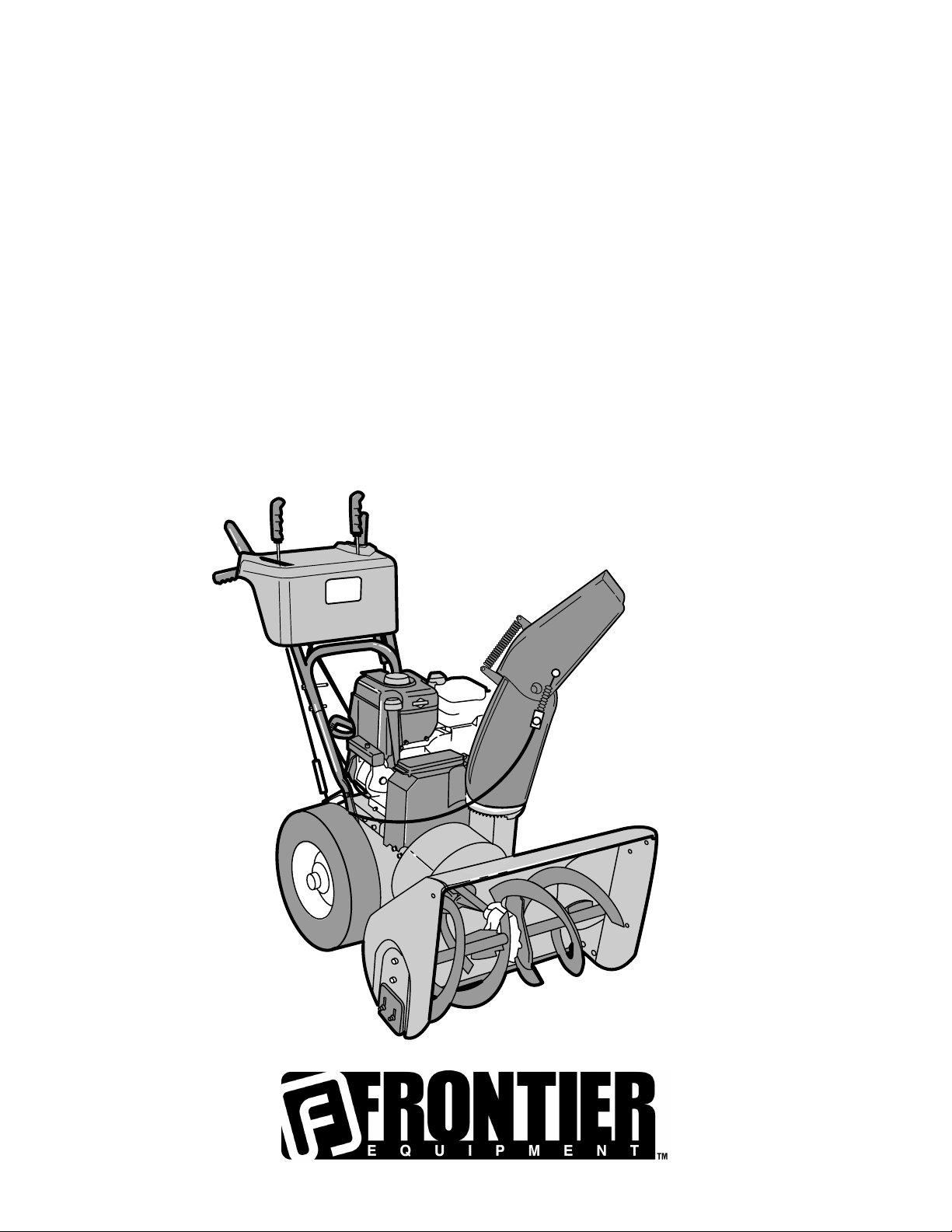
ST0927
Snow Thrower
OPERATOR’S
MANUAL
MTF−051057L
Page 2

INTRODUCTION
Congratulations on your purchase of a Frontier Snowthrower. It has been designed, engineered and manufactured to give you
the best possible dependability and performance. However, like all mechanical products, your machine will occasionally require adjustment and maintenance. This handbook should be read before operating or performing and adjustments on your
machine.
The instructions in this Owner’s Manual are written for a person with some mechanical ability. Like most service books, not
all the steps are described. Steps on how to loosen or tighten fasteners are steps anyone can follow with some mechanical
ability. Read and follow these instructions before you use the unit.
Know your product:: If you understand the unit and how the unit operates, you will get the best performance. As you read
this manual, compare the illustrations to the unit. Learn the location and the function of the controls. To help prevent an accident, follow the operating instructions and the safety rules. Keep this manual for future reference.
IMPORTANT: Many units are not assembled and are sold in cartons. It is the responsibility of the owner to make sure the assembly instructions in this manual are exactly followed. Other units are purchased in an assembled condition. On assembled
units, it is the responsibility of the owner to make sure the unit is correctly assembled. The owner must carefully check the unit
according to the instructions in this manual before it is first used.
The warranty, found in this manual, details the coverage and limitations of this product. Registration of the warranty is
necessary and must be preformed by the dealer within sixty (60) days from the date of retail sale or delivery. The
Warranty Registration Form is located on the Frontier website.
RESPONSIBILITY OF THE OWNER
The responsibility of the owners to follow the instructions below.
1. Carefully read and follow the rules for safe operation.
2. Follow all the assembly instructions.
3. Inspect the unit.
4. Make sure that the operator of the unit knows how to correctly use all standard and accessory equipment.
5. Operate the unit only with guards, shields, and other safety items in place and working correctly.
6. Correctly adjust the unit.
7. Service the unit only with authorized or approved replacement parts.
8. Complete all maintenance on the unit.
PRODUCT INFORMATION
The owner must be certain that all the product information is included with this unit.
This information includes the INSTRUCTION BOOKS, the REPLACEMENT PARTS
and the WARRANTIES. This information must be included to make
sure state laws and other laws are followed.
Read And Keep This Book For
Future Reference. This Book Contains Important Information On:
SAFETY, ASSEMBLY, OPERATION AND MAINTENANCE.
MTF−051057L
2
Page 3
RULES FOR SAFE OPERATION
This manual contains safety information to make you
aware of the hazards and risks associated with snow
throwers, and how to avoid them. The snow thrower is designed and
intended for removal of snow, and should not be used for any other
purpose. It is important that you read and understand these
instructions, and anyone operating the equipment read and
understand these instructions.
WARNING
The engine exhaust from this product contains chemicals known to the
State of California to cause cancer, birth defects, or other reproductive
harm.
A signal word (DANGER, WARNING, or CAUTION) is used with the alert
symbol to indicate the likelihood and the potential severity of injury. In
addition, a hazard symbol may be used to represent the type of hazard.
DANGER indicates a hazard which, if not avoided, will result in
death or serious injury.
WARNING indicates a hazard which, if not avoided, could result
in death or serious injury.
CAUTION indicates a hazard which, if not avoided, might result
in minor or moderate injury.
CAUTION, when used without the alert symbol, indicates a
situation that could result in damage to the equipment.
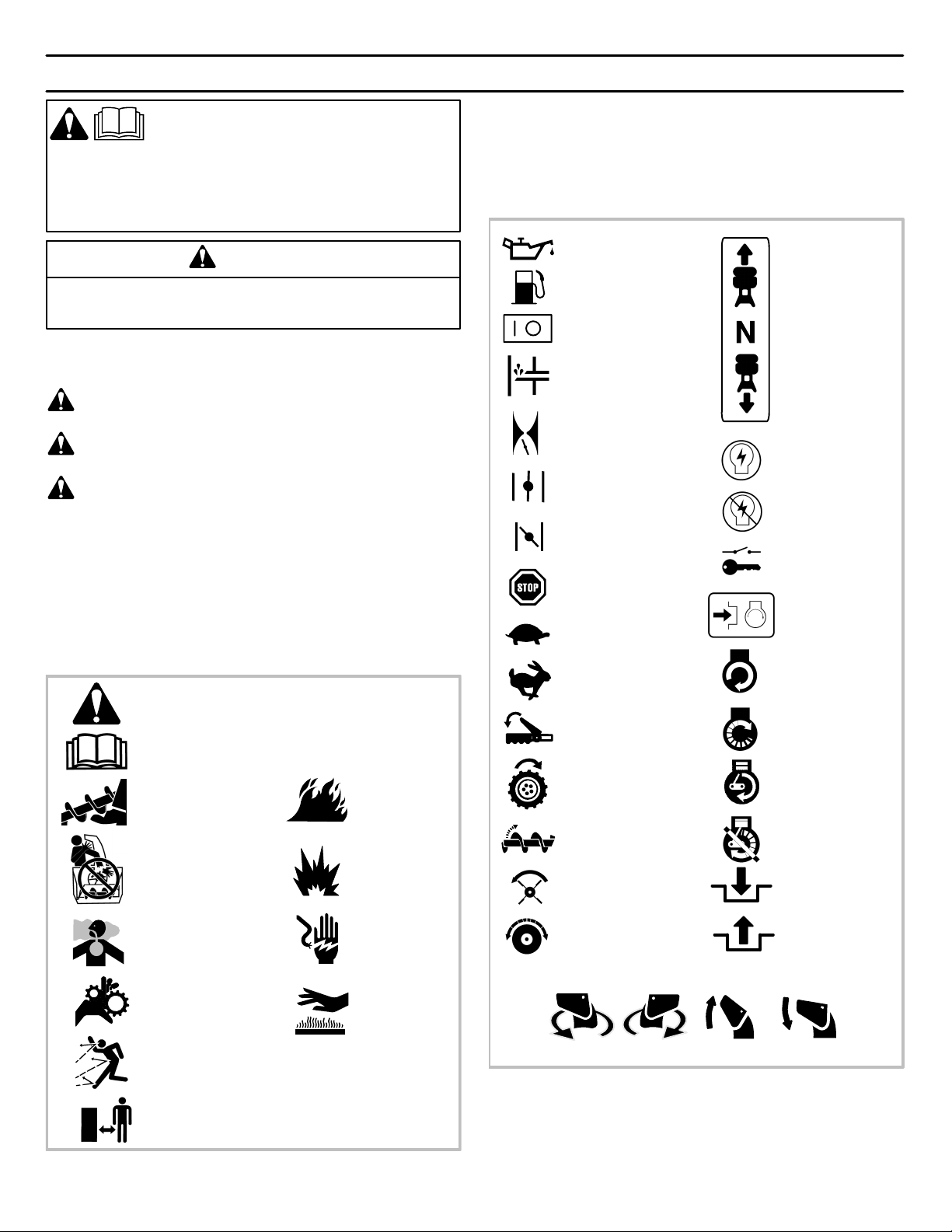
Hazard Symbols and the meanings
These symbols are used on your equipment and defined in your operating
manual. Review and understand the meanings. The use of one of these
symbols combined with a signal word will alert you to potential hazards
and how to avoid them.
Safety Alert − Identifies safety information about
hazards that can result in personal injury.
Operator’s Manual − Read and understand
before performing any activity or running
equipment.
Rotating auger
Fire
Operating Symbols and their meanings
These symbols are used on your equipment and defined in your operating
manual. It is important that you review and understand the meanings.
Failure to understand the symbols might result in harm to you.
Oil
Fuel
On Off
Primer bulb
Throttle
Choke off
Choke on
Stop
Slow
Fast
Engage
Traction
Foward
Neutral
Reverse
Ignition On
Ignition Off
Ignition Key
Push to engage
electric start
Electric
Start
Engine
Start
Engine Run
MTF−051057L
Rotating impeller
Toxic fumes
Rotating gears
Thrown objects
Keep a safe distance
from the equipment.
Explosion
Shock
Hot Surface
Auger Collector
Auger Clutch
Drive Clutch
Discharge Chute
LEFT UP
RIGHT
Chute Deflector
Engine Off
Engage
Disengage
DOWN
3
Page 4
RULES FOR SAFE OPERATION
DANGER
Avoid death or serious injury from rotating auger.
Keep hands, feet and clothing away.
Unclogging discharge chute is a hazardous activity.
• Never attempt to clear auger of debris or clogged snow while equipment is
engaged or engine is running. Clogged or blocked augers store energy
and can rotate unexpectedly, EVEN WITH ENGINE OFF.
• Stop engine and disconnect spark plug wire when performing maintenance
on equipment.
• Never leave the equipment unattended while engine is running. Always
disengage the auger and traction controls, stop engine, and remove keys.
• Keep children, pets, and others out of the area during operation. Children
are often attracted to the equipment. Be mindful of all persons present.
• Keep all loose clothing far away from front of snow thrower and auger.
Scarfs, mittens, dangling drawstrings, loose clothes and pants can quickly
become caught in the rotating device and dismemberment will occur. Tie
up long hair and remove jewerly.
• The snow thrower is intended to remove snow only. Do not use for other
purposes other than what is intended.
• Do not clear snow across the face of slopes. Exercise extreme caution when
changing direction on slopes. Do not attempt to clear steep slopes.
• Do not use the snow thrower on surfaces above ground level such as roofs
of residences, garages, porches or other such structures or buildings.
DANGER
Discharge chute contains rotating impeller to throw snow.
Never clear or unclog discharge chute with your hands, or
while engine is running.
Fingers can quickly become caught and traumatic
amputation or severe laceration can result.
• Unclogging the discharge chute is a hazardous activity. Clogged or
blocked augers store energy and can rotate unexpectedly.
• Never place hands in or near discharge chute.
• With engine OFF, wait for all moving parts to cease movement, then with a
stick, clear the chute. Even with engine off, parts may rotate and
dismemberment can occur.
• Clogged snow can hide other obstructions in the chute and cause damage
to the equipment, impeller or auger. Take precautions when restating the
equipment after snow removal.
DANGER
Objects can be picked up by auger and thrown from chute.
Never throw snow toward people or cars, and never allow
anyone in front of the snow thrower.
• Be aware of your enviroment while operating equipment. Running over
items such as, gravel, doormats, newspapers, toys, and rocks hidden
under snow, can all be thrown from chute or jam in the auger.
• Always be aware of the direction the snow is being thrown. Nearby
pedestrians, pets or property may be harmed by objects being thrown.
• Familiarize yourself with the area you plan to work. Mark off boundarties of
walkways and driveways to prevent property damage, or throwing objects.
• Take caution when snow throwing in unfamiliar areas. Stay alert for hidden
hazards and traffic.
• After striking a foreign object, turn engine OFF, wait for moving parts to
cease movement, and check immediately for damage. If damaged, repair
before starting and operating snow thrower.
• With engine OFF, wait for moving parts to stop and always use a stick to
clear discharge chute.
• If unit vibrates abnormally, turn engine OFF. Vibration is generally a
warning of trouble. See an authorized dealer if necessary for repairs.
WARNING
Rotating gears can contact or entangle hands, feet, hair,
clothing, or accessories.
Traumatic amputation or severe laceration can result.
• Always operate equipment with all guards in place.
• Keep hands and feet away from rotating gears.
• Tie up long hair and remove jewelry.
• Do not wear loose-fitting clothing, dangling drawstrings or items that could
become caught.
WARNING
Engines give off carbon monoxide, an odorless, colorless,
poison gas.
Breathing carbon monoxide can cause nausea, fainting or
death.
• Start and run engine outdoors.
• Do not start or run engine in enclosed area, even if doors or
windows are open.
MTF−051057L
4
Page 5
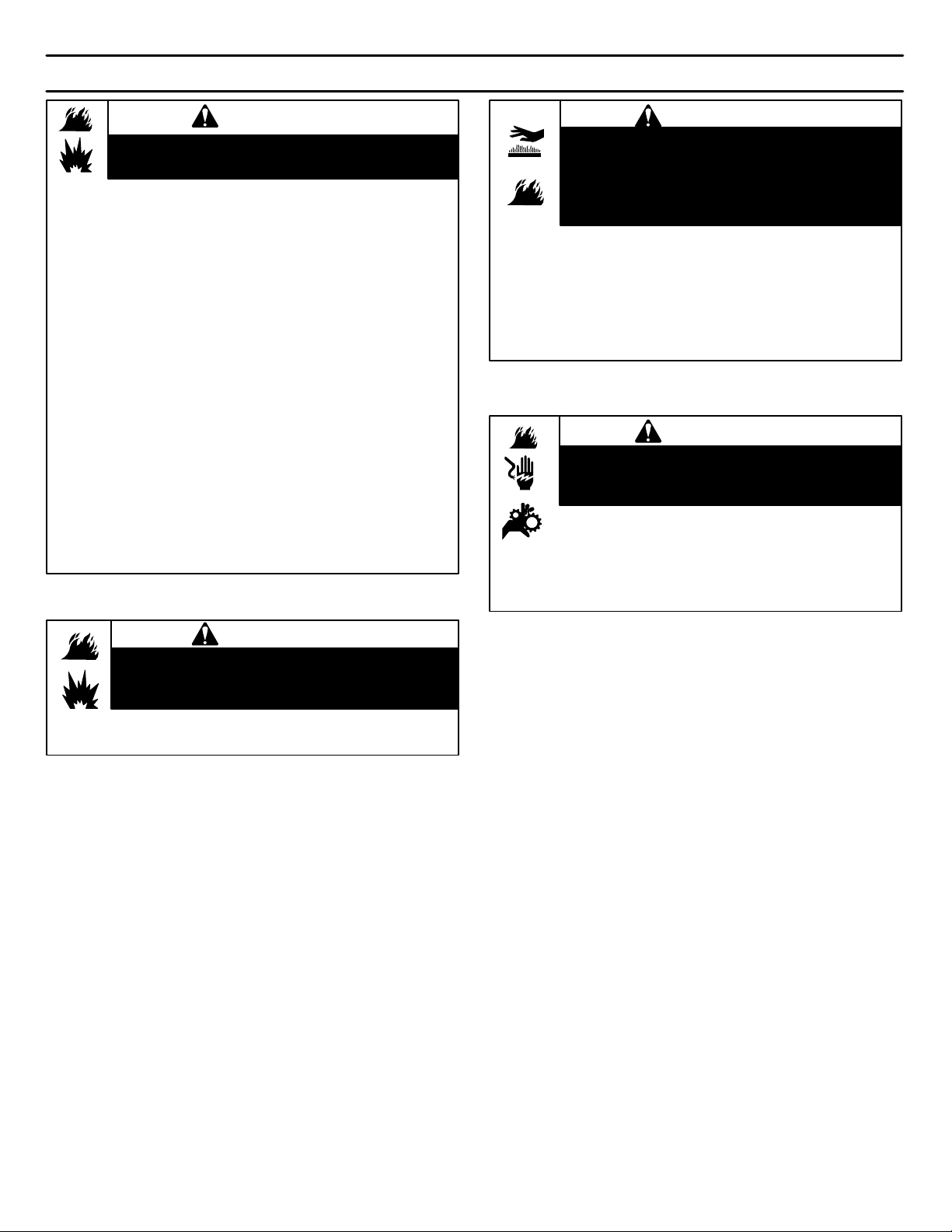
RULES FOR SAFE OPERATION
WARNING
Gasoline and its vapors are extremely flammable and explosive.
Fire or explosion can cause severe burns or death.
WHEN ADDING FUEL
• Turn engine OFF and let engine cool at least 2 minutes before removing
gas cap.
• Fill fuel tank outdoors or in well-ventilated area.
• Do not overfill fuel tank.
• Keep gasoline away from sparks, open flames, pilot lights, heat, and other
ignition sources.
• Check fuel lines, tank, cap, and fittings frequently for cracks or leaks.
Replace if necessary.
WHEN STARTING ENGINE
• Make sure spark plug, muffler, fuel cap and air cleaner are in place.
• Do not crank engine with spark plug removed.
• If fuel spills, wait until it evaporates before starting engine.
• If engine floods, set choke to OPEN/RUN position, place throttle in FAST
and crank until engine starts.
WHEN OPERATING EQUIPMENT
• Do not choke carburetor to stop engine.
WHEN TRANSPORTING EQUIPMENT
• Transport with fuel tank EMPTY.
WHEN STORING GASOLINE OR EQUIPMENT WITH FUEL IN TANK
• Store away from furnaces, stoves, water heaters or other appliances that
have pilot light or other ignition source because they can ignite gasoline
vapors.
WARNING
Running engines produce heat. Engine parts, especially muffler,
become extremely hot.
Severe thermal burns can occur on contact.
Combustible debris, such as leaves, grass, brush, etc. can catch
fire.
• Allow muffler, engine cylinder and fins to cool before touching.
• Remove accumulated combustibles from muffler area and cylinder
area.
• Install and maintain in working order a spark arrester before using
equipment on forest-covered, grass-covered, brush-covered
unimproved land. The state of California requires this (Section 4442 of
the California Public Resources Code). Other states may have similar
laws. Federal laws apply on federal land.
WARNING
Unintentional sparking can result in fire or electric shock.
Unintentional start-up can result in entanglement, traumatic
amputation, or laceration.
BEFORE PERFORMING ADJUSTMENTS OR REPAIRS
• Disconnect spark plug wire and keep it away from spark plug.
WHEN TESTING FOR SPARK
• Use approved spark plug tester.
• Do not check for spark with spark plug removed.
WARNING
Starting engine creates sparking.
Sparking can ignite nearby flammable gases.
Explosion and fire could result.
• If there is natural or LP gas leakage in area, do not start engine.
• Do not use pressurized starting fluids because vapors are flammable.
MTF−051057L
5
Page 6

MTF−051057L
TABLE OF CONTENTS
HAZARD SYMBOLS AND THE MEANINGS 3. . . . . . . . . . . . . . . . . . . . . . .
OPERATING SYMBOLS AND THEIR MEANINGS 3. . . . . . . . . . . . . . . . . .
SAFETY DECALS 7. . . . . . . . . . . . . . . . . . . . . . . . . . . . . . . . . . . . . . . . . . . . . .
WARRANTY 8. . . . . . . . . . . . . . . . . . . . . . . . . . . . . . . . . . . . . . . . . . . . . . . . . . .
OWNER’S INFORMATION 8. . . . . . . . . . . . . . . . . . . . . . . . . . . . . . . . . . . . . . .
ASSEMBLY 9. . . . . . . . . . . . . . . . . . . . . . . . . . . . . . . . . . . . . . . . . . . . . . . . . . . .
TOOLS REQUIRED FOR ASSEMBLY 9. . . . . . . . . . . . . . . . . . . . . . . . . . .
CONTENTS OF SHIPPING CARTON 9. . . . . . . . . . . . . . . . . . . . . . . . . . .
PARTS BAGS CONTENTS 9. . . . . . . . . . . . . . . . . . . . . . . . . . . . . . . . . . . .
UNPACKING 10. . . . . . . . . . . . . . . . . . . . . . . . . . . . . . . . . . . . . . . . . . . . . . . . .
UPPER HANDLE AND CRANK ASSEMBLY 11. . . . . . . . . . . . . . . . . . . . . .
CHECK THE CABLES 11. . . . . . . . . . . . . . . . . . . . . . . . . . . . . . . . . . . . . . . . .
HOW TO SET THE LENGTH OF THE CABLES 11. . . . . . . . . . . . . . . . . . .
REMOTE CHUTE CONTROL KNOB 12. . . . . . . . . . . . . . . . . . . . . . . . . . . .
SPEED SELECT KNOB 12. . . . . . . . . . . . . . . . . . . . . . . . . . . . . . . . . . . . . . .
HOW TO INSTALL THE SPEED CONTROL ROD 12. . . . . . . . . . . . . . . . .
SNOW CHUTE ASSEMBLY 13. . . . . . . . . . . . . . . . . . . . . . . . . . . . . . . . . . . .
IMPORTANT! BEFORE YOU START OPERATING 13. . . . . . . . . . . . . . . .
OPERATION 14. . . . . . . . . . . . . . . . . . . . . . . . . . . . . . . . . . . . . . . . . . . . . . . . . . .
ENGINE AND SNOWTHROWER CONTROLS 14. . . . . . . . . . . . . . . . . . . .
SNOWTHROWER OPERATION 15. . . . . . . . . . . . . . . . . . . . . . . . . . . . . . . .
WHEEL LOCK OUT PIN 16. . . . . . . . . . . . . . . . . . . . . . . . . . . . . . . . . . . . . . .
HOW TO SET THE DRIFT CUTTERS 16. . . . . . . . . . . . . . . . . . . . . . . . . . .
BEFORE STARTING ENGINE 17. . . . . . . . . . . . . . . . . . . . . . . . . . . . . . . . . .
CHECK THE OIL 17. . . . . . . . . . . . . . . . . . . . . . . . . . . . . . . . . . . . . . . . . . . . .
FILL GAS 17. . . . . . . . . . . . . . . . . . . . . . . . . . . . . . . . . . . . . . . . . . . . . . . . . . . .
TO STOP ENGINE 18. . . . . . . . . . . . . . . . . . . . . . . . . . . . . . . . . . . . . . . . . . . .
TO START ENGINE 18. . . . . . . . . . . . . . . . . . . . . . . . . . . . . . . . . . . . . . . . . . .
HOW TO CLEAR A CLOGGED DISCHARGE CHUTE 20. . . . . . . . . . . . .
HOW TO USE THE CLEAN-OUT TOOL 20. . . . . . . . . . . . . . . . . . . . . . . . .
OPERATING TIPS 21. . . . . . . . . . . . . . . . . . . . . . . . . . . . . . . . . . . . . . . . . . . .
SERVICE RECOMMENDATIONS 22. . . . . . . . . . . . . . . . . . . . . . . . . . . . . . . . .
MAINTENANCE 23. . . . . . . . . . . . . . . . . . . . . . . . . . . . . . . . . . . . . . . . . . . . . . . .
LUBRICATION 23. . . . . . . . . . . . . . . . . . . . . . . . . . . . . . . . . . . . . . . . . . . . . . .
ENGINE 25. . . . . . . . . . . . . . . . . . . . . . . . . . . . . . . . . . . . . . . . . . . . . . . . . . . . .
AUGER HOUSING HEIGHT ADJUSTMENT 26. . . . . . . . . . . . . . . . . . . . . .
BELT ADJUSTMENT 27. . . . . . . . . . . . . . . . . . . . . . . . . . . . . . . . . . . . . . . . . .
HOW TO REPLACE THE BELTS 28. . . . . . . . . . . . . . . . . . . . . . . . . . . . . . .
BELT GUIDE ADJUSTMENT 31. . . . . . . . . . . . . . . . . . . . . . . . . . . . . . . . . . .
TRACTION DRIVE CABLE ADJUSTMENT 32. . . . . . . . . . . . . . . . . . . . . . .
HOW TO ADJUST OR REPLACE THE FRICTION WHEEL 33. . . . . . . . .
HOW TO REMOVE THE SNOW HOOD 36. . . . . . . . . . . . . . . . . . . . . . . . .
AUGER SHEAR BOLT REPLACEMENT 37. . . . . . . . . . . . . . . . . . . . . . . . .
TO ADJUST OR REPLACE THE SPARK PLUG 37. . . . . . . . . . . . . . . . . . .
STORAGE 38. . . . . . . . . . . . . . . . . . . . . . . . . . . . . . . . . . . . . . . . . . . . . . . . . . . . .
TROUBLE SHOOTING CHART 39. . . . . . . . . . . . . . . . . . . . . . . . . . . . . . . . . .
REPLACEMENT PARTS 40. . . . . . . . . . . . . . . . . . . . . . . . . . . . . . . . . . . . . . . . .
PARTS SCHEMATICS 41. . . . . . . . . . . . . . . . . . . . . . . . . . . . . . . . . . . . . . . . . . .
SPECIFICATIONS 60. . . . . . . . . . . . . . . . . . . . . . . . . . . . . . . . . . . . . . . . . . . . . .
6
Page 7
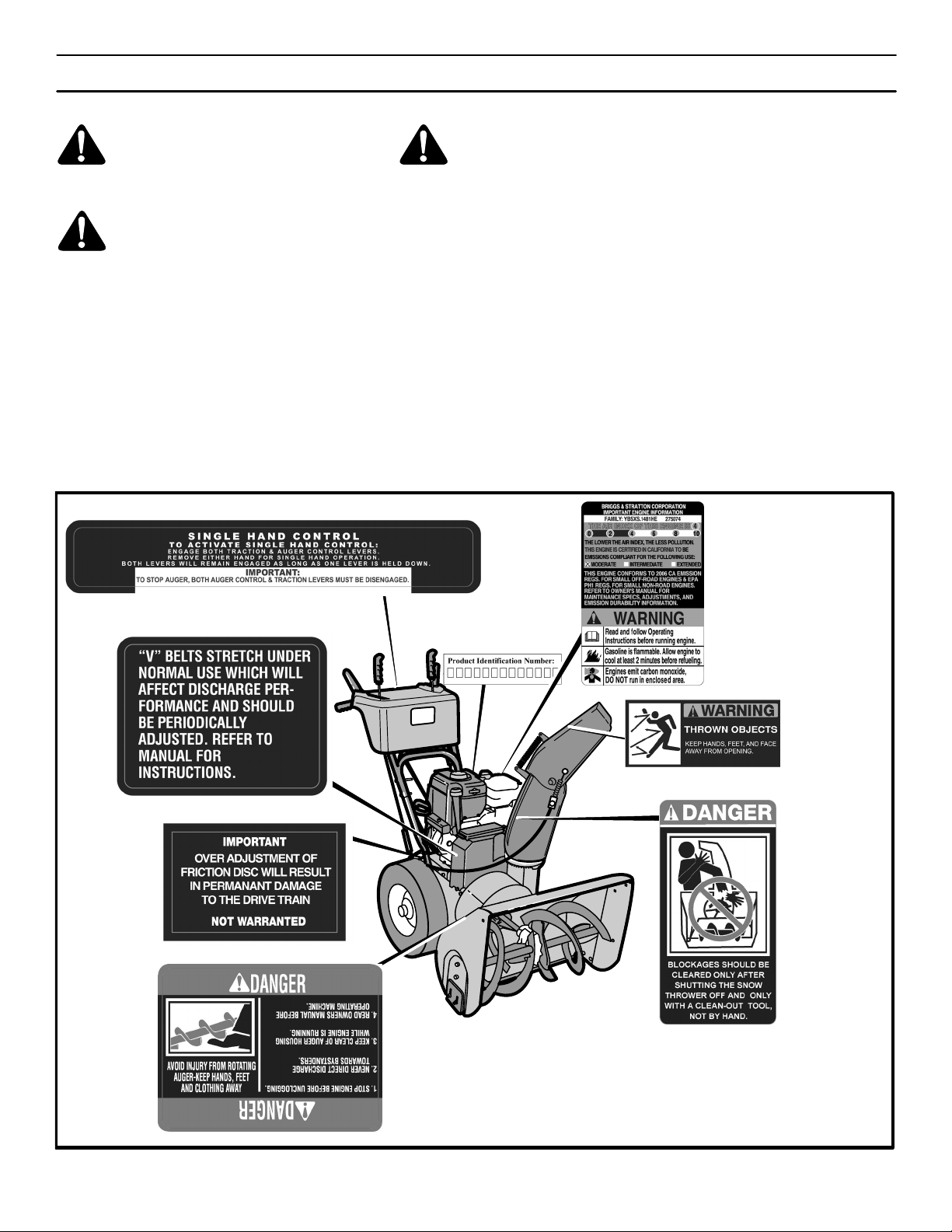
SAFETY DECALS
WARNING: If safety decals are damaged or missing, replace immediately.
Look for this symbol to indicate important safety precautions. This symbol indicates: “Attention! Become Alert! Your Safety Is At Risk.”
Before operation of your snowthrower, read the safety decals as shown on your snowthrower. The cautions and
warnings are for your safety. To avoid a personal injury or
damage to your snowthrower, understand and follow all
safety decals. If you have any questions regarding the
meaning or how to comply with the instructions, do not operate until you understand the purpose for the warning or
danger given in the safety decal. If you do not understand
the meaning, then thoroughly read all safety and operation
instructions in this Owner’s Manual or contact your local
dealer.
If any safety decals become worn or damaged and cannot
be read, order replacement decals from your local dealer.
Identifying Your Snowthrower
The snowthrower has two (2) identifying numbers: (1) unit
model number: (2) unit serial number. The two preceding
numbers are required to insure that the proper replacement parts are obtained when required. If you have any
questions concerning parts, service, or technical data, contact the dealer where the unit was purchased.
For complete warranty information refer to the warranty in
the Owner’s Information section of this manual.
MTF−051057L
Figure 1
7
Page 8

OWNER’S INFORMATION
THREE YEAR LIMITED WARRANTY
Murray warrants to the original purchaser of this Frontier Branded Snowthrower that this unit shall be free from defects in
material and workmanship under normal use and service for a period of Three (3) Year from the date of purchase; however,
this warranty does not cover accessories (such as electric starters) and Normal Wear Parts (except as noted below) as the
companies that manufacture these items furnish their own warranties and provide service through their authorized field
service facilities. For additional information, see the warranties covering these particular parts. If you are uncertain whether
your unit contains or is equipped with one or more of these parts, consult your dealer prior to purchase. Subject to the terms
and conditions noted in this Limited Warranty, we shall, at our option, repair or replace at no cost to the original purchaser
any part covered by this Limited Warranty during the applicable warranty period.
Normal Wear Parts are defined as drive belts, augers, shear pins, tires and headlights. These parts are warranted to be free
from defects in material and workmanship as delivered with the product. Any claim for repair or replacement of Normal Wear
Parts must be made within thirty (30) days of the date of purchase. No claims involving damage caused from material use,
abuse or misuse will be honored.
This Murray Three (3) Year Limited Warranty for your Frontier Branded Snowthrower is your exclusive remedy; however,
this warranty is void or does not apply to any unit that has been tampered with, altered, misused, abused. If used for
commercial and/or professional (non−homeowner) uses, the duration of this warranty is ninety (90) days after the date of
purchase. Your warranty does not cover minor mechanical adjustments which are not due to any defect in material or
workmanship. For assistance in making such adjustments, consult your Operator’s Manual.
The engine on this Frontier Branded Snowthrower is warranted to the original purchaser for a Three (3) Year Limited
Warranty by the equipment manufacturer. See your engine manual for information regarding the warranty policy and items
covered under warranty. See your authorized John Deere/Frontier Dealer for service or replacement parts.
To make a claim under this Murray Three (3) Year Limited Warranty for your Frontier Branded Snowthrower, return the unit
(or if authorized in advance, the defective part) along with your proof of purchase to an Authorized John Deere/Frontier Dealer
near you. To locate the nearest Authorized John Deere/Frontier Dealer, check the Yellow Page listings in your local telephone
directory. If you return the entire unit, John Deere/Frontier will repair all warranty items. If authorize to return the defective
part only, John Deere/Frontier will either replace or repair the part. This Murray Three (3) Year Limited Warranty for your
Frontier Branded Snowthrower gives you specific legal rights, and you may also have other rights which vary from state to
state.
This Limited Warranty is given in lieu of all other expressed and implied warranties including the implied
warranty of merchantability and warranty of fitness for a particular purpose. If you need additional information on this
written warranty or assistance in obtaining service, contact you local John Deere/Frontier Dealer.
MB
FOR YOUR RECORDS
DATE PURCHASED:
MODEL NO:
SERIAL NO:
MTF−051057L
STORE WHERE PURCHASED:
ADDRESS:
CITY: STATE:
TELEPHONE :
Record this information about your unit so that you will
be able to provide it in case of loss or theft.
8
Page 9
ASSEMBLY
TOOLS REQUIRED FOR ASSEMBLY
1 − Knife
2 − 1/2” wrenches (or adjustable wrenches)
2 − 9/16” wrenches (or adjustable wrenches)
2 − 3/4” wrenches (or adjustable wrenches)
1 − 3/8” wrenches (or adjustable wrenches)
1 − Pair pliers or screw driver (to spread cotter pin)
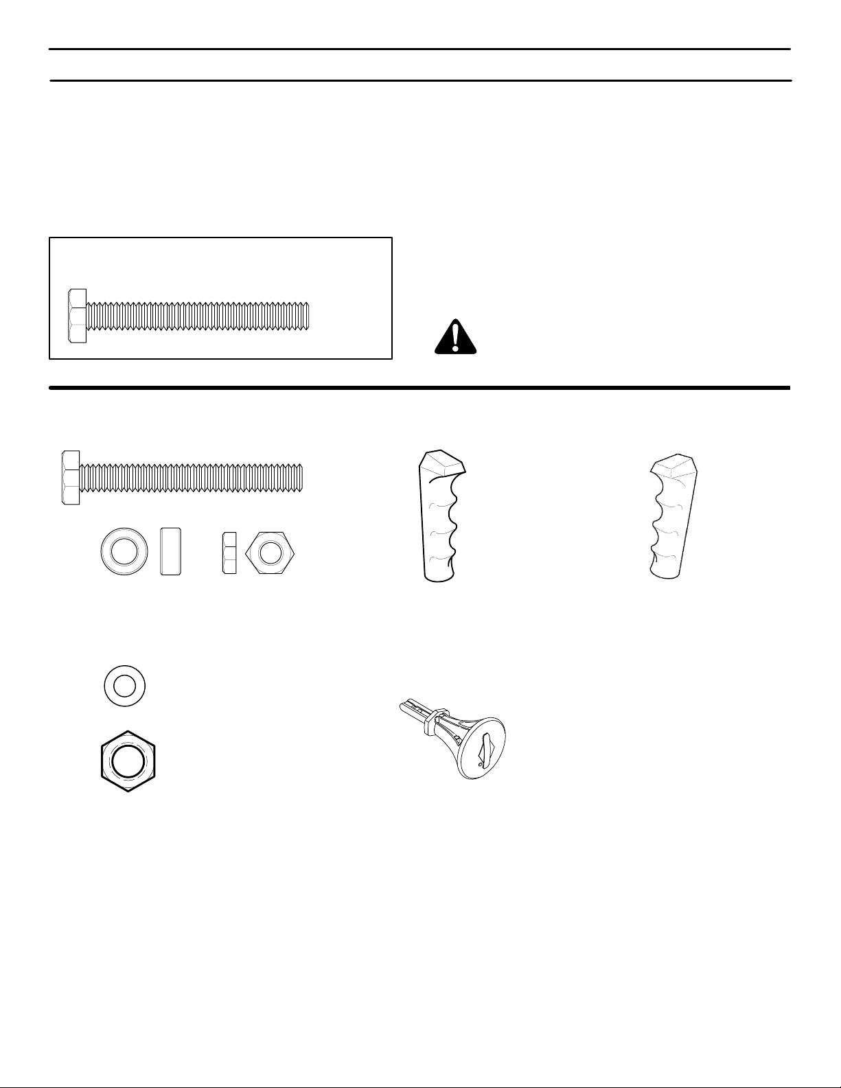
HOW TO MEASURE SCREW SIZE
LENGTH
DIAMETER
PARTS BAGS CONTENTS:
*2− Shear Bolt
CONTENTS OF SHIPPING CARTON
1− Snowthrower
1− Container of Fuel Stabilizer (Located in Parts Bag)
1− Crank Assembly
1− Parts Bag
WARNING: Always wear safety glasses or eye
shields while assembling snowthrower.
* 2−Spacer
1 − Washer
1 − Nut
* Non Assembly parts are found in toolbox located on top of belt cover.
*2− Nut
1 − Shift Lever Knob
(not actual size)
1 − Ignition Keys
1 − Remote Chute Knob
(not actual size)
MTF−051057L
9
Page 10
ASSEMBLY
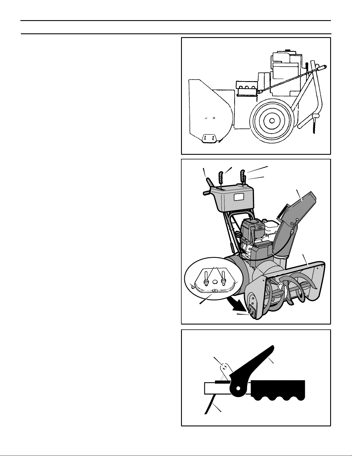
Figure 2 shows the snowthrower in the shipping position.
Figure 3 shows the snowthrower completely assembled.
Reference to right and left hand side of the snowthrower is
from the operator’s position at the handle.
UNPACKING
1. Locate the two tear tabs at the bottom of the carton.
2. Pull the tear tape no more than twelve inches (30.48cm.)
at a time. Re−grasp tape next to the carton and pull
again. Repeat until all the tape is torn off.
3. After the tape has been completely removed from the
carton, remove the carton from the base. Cut all four corners and fold the sides toward the center for easy disposal.
4. Remove the plastic bag that covers the unit.
5. Locate and remove the parts bag.
NOTE: Set the fuel stabilizer aside until adding
gasoline to the fuel tank. We recommend that fuel
stabilizer is added to the fuel each time that gasoline
is added to the fuel tank.
6. For shipping purposes, the height adjust skids are at-
tached to the pallet. Remove the screw that secures
each height adjust skid to the pallet. (See Figure 2).
Auger Drive
Lever
Screw
Height Adjust
Speed Shifter Lever
Skid
Figure 2
Traction Drive Lever
Remote Chute Control
Snow Chute Deflector
Auger Housing
Figure 3
7. Roll the snowthrower off the carton by pulling on the lower handle.
CAUTION: DO NOT back over cables.
8. Remove the packing material from the handle assembly.
9. Cut ties securing the clutch control cables to the lower
handle.
NOTE: If the cables have become disconnected from the
clutch levers, reinstall the cables as shown in Figure 4.
MTF−051057L
10
”Z” Fitting
Cable
Drive Lever
Figure 4
Page 11
ASSEMBLY
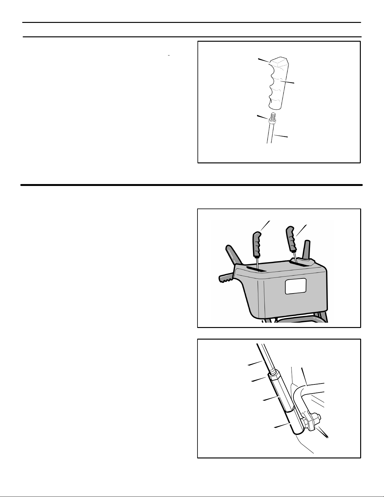
UPPER HANDLE AND CRANK ASSEMBLY
For shipping purposes, the handles were assembled
together with the fasteners in the LOWER holes. When
assembled, make sure that the fasteners are in the
UPPER holes and that the eye bolt is mounted in the
LOWER hole on the left side as shown in Figure 5.
Adaptor Boot
Flatwasher
Locknut
Bolt
Lockwasher
Nut
1. On the right side of the handle, loosen, but do not remove
the fasteners (bolt, flatwasher, lockwasher and nut) that
are assembled in the lower hole.
2. On the left side of the handle, remove the fasteners (bolt,
flatwasher, lockwasher and nut) that are assembled in
the LOWER holes.
3. Remove the fasteners and the crank assembly eyebolt
from the UPPER holes of the lower handle.
4. Raise upper handle into operating position. Upper handle should be to the outside of the lower handle.
NOTE: Make sure the cables are not caught between
the upper and lower handle.
5. On the left side of the handle, install the fasteners that
were removed in step 2. Make sure these fasteners are
installed in the UPPER holes as shown in Figure 5.
6. Install the fasteners and the crank assembly eyebolt that
were removed in step 3. Make sure to install the eyebolt
in the LOWER holes as shown in Figure 5. DO NOT tighten until all fasteners are in place.
7. Attach the crank rod to the universal joint assembly with
the hair pin (see Figure 6).
8. Tighten nut on eye bolt. Make sure eye bolt is properly
aligned and the crank can freely rotate.
9. Tighten all handle bolts.
NOTE: Make sure crank does not touch carburetor
cover.
Crank
Eye Bolt
Flatwasher
Hair Pin
Universal Joint
Flatwasher
Figure 5
Crank Rod
Assembly
Figure 6
CHECK THE CABLES
1. If control cables have become unattached from motor
mount frame, reconnect cables as shown in Figure 7.
2. For cable adjustments, see “How To Check And Adjust
The Cables” in the MAINTENANCE section.
HOW TO SET
THE LENGTH OF THE CABLES
The cables were adjusted at the factory and no adjustments
should be necessary. However, after the handles are put in
the operating position, the cables can be too tight or too
loose. If an adjustment is necessary, see “How To Check And
Adjust The Cables” in the MAINTENANCE section.
MTF−051057L
11
Traction Drive Cable
Auger Drive Cable
Figure 7
Page 12
ASSEMBLY
REMOTE CHUTE CONTROL KNOB
1. Thread the knob onto the lever as far as possible. Make
sure that the knob points forward (See Figure 8).
LIp
2. Tighten the jam nut against the knob securely.
SPEED SELECT KNOB
1. Thread the knob onto the lever as far as possible. Make
sure that the knob points forward (See Figure 8).
2. Tighten the jam nut against the knob securely.
HOW TO INSTALL
THE SPEED CONTROL ROD
1. Put the speed select lever to the NEUTRAL position.
See Figure 9.
Nut
Speed Select Lever
Knob
Lever
Figure 8
Remote Chute
Control Lever
2. Attach the ball joint, located on the bottom end of the
speed control rod, to the shift yoke assembly. See
Figure 10. The fasteners (washer and nut) are in the
parts bag.
3. The length ot the ball joint and speed control rod have
been pre−adjusted at the factory. If an adjustment is required, loosen the nut. Remove the fasteners to disconnect the ball joint from the shift yoke assembly. To
lengthen or shorten the speed control rod, turn the
adapter to obtain the correct length.
4. Make sure the speed select lever functions correctly.
Move the speed select lever through all speeds.
Speed Control Rod
Nut
Figure 9
Shift Yoke Assembly
Adapter
Ball Joint
Fasteners
Figure 10
MTF−051057L
12
Page 13
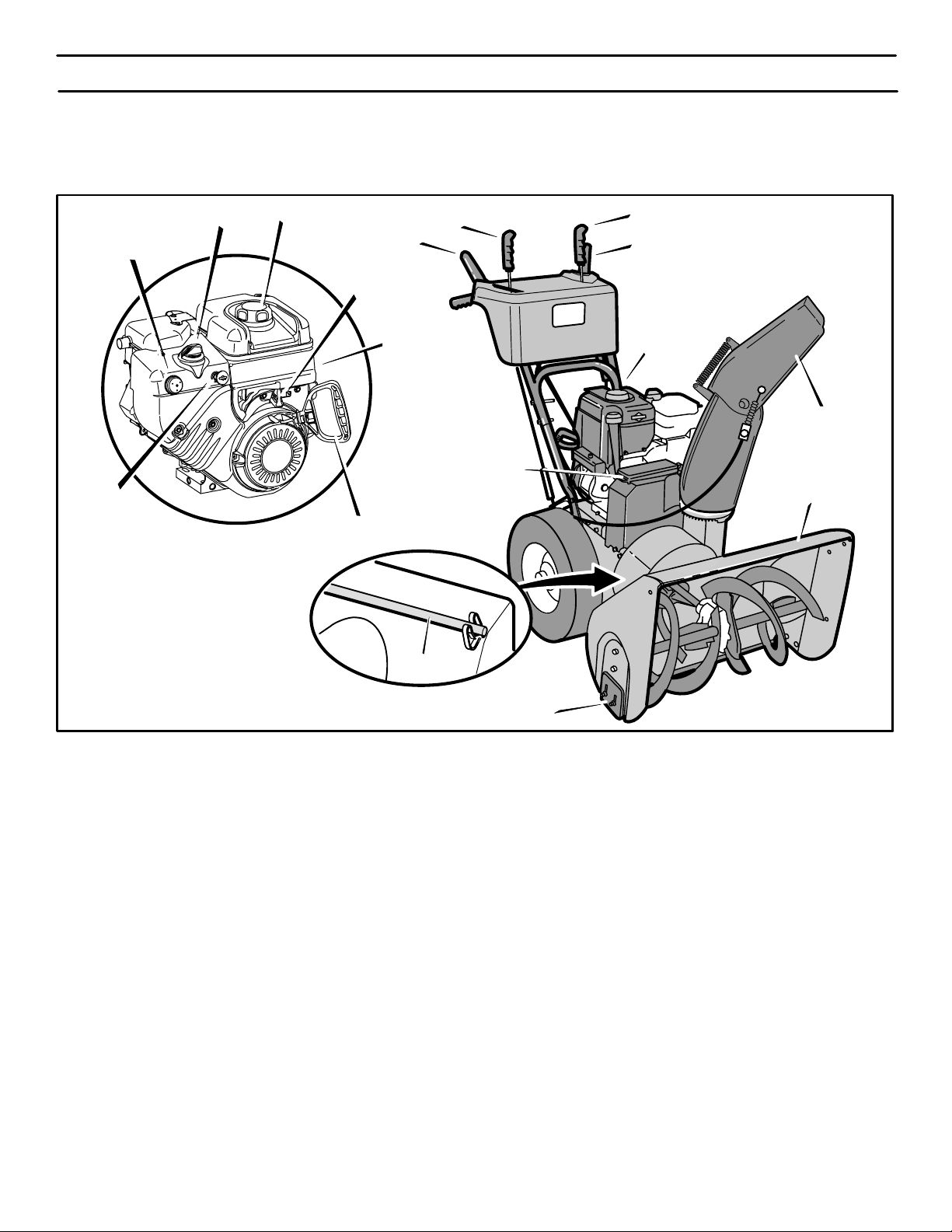
SNOW CHUTE ASSEMBLY
1. Remove back carriage bolt (See Figure 11).
ASSEMBLY
2. Tilt chute back into operating position.
3. Replace carriage bolt from inside of chute.
4. Replace flatwasher and nylon locknut on outside of
flange.
5. Tighten carriage bolt securely.
NOTE: check all carriage bolts in flange for tightness.
DO NOT overtighten.
Operating
Position
Carriage Bolt
Flange
Chute Deflector
Locknut
Flatwasher
Figure 11
CHECK THE TIRES
The tires were over inflated for shipment. Check the tire
pressure in the tires. See the sidewall of the tire for the
proper inflation.
NOTE: This snowthrower was shipped WITH OIL in the engine. See “Before Starting Engine”
instructions in the Operation section of this manual before starting engine.
IMPORTANT! BEFORE YOU START
OPERATING
r Check the fasteners. Make sure all fasteners are
tight.
r On electric start models, the unit was shipped with
the starter cord plugged into the engine. Before
operating, unplug the starter cord from the engine.
MTF−051057L
13
Page 14
OPERATION
READ THIS OWNER’S MANUAL AND SAFETY RULES BEFORE OPERATING YOUR SNOWTHROWER. Compare the
illustrations with your SNOWTHROWER to familiarize yourself with the location of various controls and adjustments. Save
this manual for future reference.
Primer Button
Ignition Key
Choke Control
Gas Fill
Auger Drive Clutch Lever
Throttle Control
Starter Handle
Speed Select Lever
Lever
Electric
Start Button
Remote Chute Control
Traction Drive Clutch Lever
Crank
Snow Chute
Deflector
Toolbox
Auger Housing
Clean-out Tool
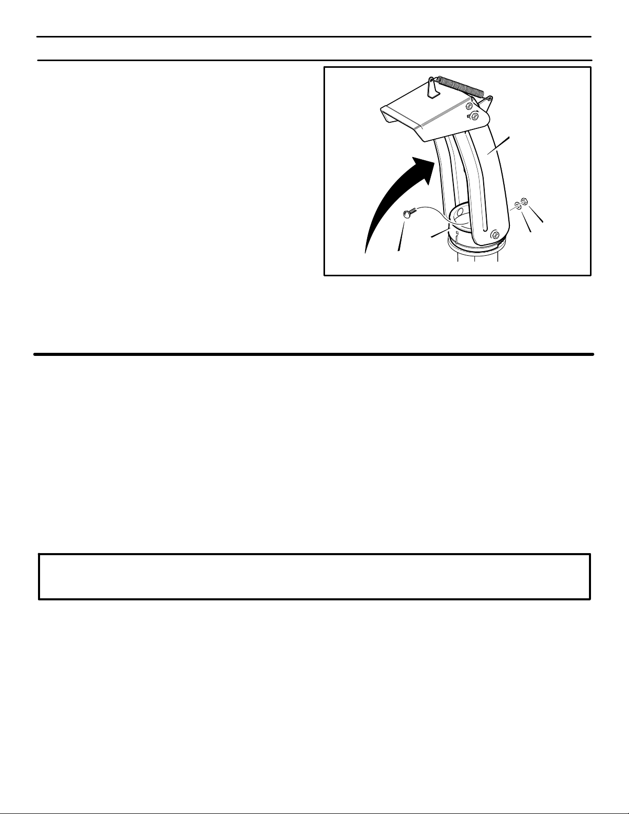
ENGINE AND SNOWTHROWER CONTROLS
ENGINE CONTROLS
Throttle Control Lever − Controls the engine speed.
Choke Control− Use to start a cold engine.
Electric Start Button− Used to start the engine using the
120 volt electric starter.
Prime Button− Used to inject fuel directly into carburetor
manifold to insure fast starts in cool weather.
Ignition Key− Must be inserted to start engine. Pull out to
stop. Do not turn ignition key.
Starter Handle− Starts the engine manually.
SNOWTHROWER CONTROLS
Speed Select Lever− Allows the operator to use one of six
(6) forward and two (2) reverse speeds. To shift, move speed
select lever to desired position.
NOTE: Do not move speed select lever while Traction
Drive Clutch is engaged. This may result in severe
damage to drive system.
MTF−051057L
Height
Adjust Skid
Figure 12
Auger Drive Clutch Lever− Used to engage and disengage
the auger and impeller. To engage push down, to disengage
release.
Traction Drive Clutch Lever− Used to propel snowthrower
forward or reverse. Push down to engage, release to
disengage.
Snow Chute Deflector− Changes the direction the snow is
blown.
Remote Chute Control− Push forward to discharge snow
down. Pull back to discharge snow high and far.
Crank− Used to change direction of the snow discharge.
Turn handle clockwise to turn chute to right. Turn handle
counter clockwise to turn chute to left.
Height Adjust Skid− Used to adjust ground clearance of
auger housing.
Toolbox − Spare shear pins and spacers are located in
toolbox.
Clean-Out Tool − Use the clean-out tool to remove snow and
debirs from the discharge chute and the auger housing.
14
Page 15
OPERATION
The operation of any snowthrower can result in foreign objects being thrown into the eyes,which can
result in severe eye damage. Always wear safety glasses or eye shields before beginning snowthrower
Operation. We recommend standard safety glasses or Wide Vision Safety Mask for over spectacles.
SNOWTHROWER OPERATION
The most effective use of the snowthrower will be established
by experience, taking into consideration the terrain, wind
conditions and building location which will determine the
direction of the discharge chute.
NOTE: Do not blow snow toward a building as hidden
objects could be blown with sufficient force to cause
damage.
TO STOP YOUR SNOWTHROWER
1. To stop throwing snow, release the auger drive lever.
(see Figure 13).
2. To stop the wheels, release the traction drive lever.
3. To stop the engine, push the throttle control lever to off
and pull out the ignition key.
TO CONTROL SNOW DISCHARGE
1. Rotate the crank to set the direction (left to right) of the
discharge chute (see Figure 12).
2. Push the remote chute lever forward to discharge the
snow down. Pull the remote chute lever back to discharge the snow high and far (see Figure 13).
HOW TO MOVE FORWARD AND BACKWARD
TO THROW SNOW
1. Push down the auger driver lever (right hand). See
Figure 13.
2. To stop throwing snowl, release the auger drive lever.
NOTE: When clearing wet, heavy snow, it is
recommended that the ground speed of the unit be
reduced, maintain full throttle and do not attempt to
clear the full width of the unit.
For additional operating instructions see “Operating
Tips” in the Operation section.
WARNING: Read Owner’s Manual before operating machine. This machine can be dangerous
if used carelessly.
Never operate the snowthrower without all guards,
covers, and shields in place.
Never direct discharge towards windows or allow bystanders near machine while engine is running.
Stop the engine whenever leaving the operating position.
Disconnect spark plug before unclogging the impeller
housing or the discharge chute and before making repairs or adjustments.
When leaving the machine, remove the ignition key.
To reduce the risk of fire, keep the machine clean and
free from spilled gas, oil and debris.
1. Start the engine. See “To Start Engine” in the Operation
section.
NOTE: Always release the traction drive lever before
moving the speed select lever.
2. Ground speed is determined by snow conditions. Set the
speed select lever in one of the following positions.
1−2 Wet, Heavy, Slushy, Extra Deep
3 Moderate
4−5 Very Light
6 Transport Only
IMPORTANT: Before operating, make sure the area in
front of snowthrower is clear of bystanders or
obstacles.
3. Engage the traction drive lever (see Figure 13). As the
snowthrower starts to move, maintain a firm hold on the
handles and guide the snowthrower along the cutting
path. Do not attempt to push the snowthrower.
4. To stop forward motion, release the traction drive lever.
5. To move the snowthrower backwards, move the speed
select lever into either first or second reverse position
and engage the traction drive lever.
MTF−051057L
Speed Select
Auger Drive Lever
Lever
Remote
Chute Lever
Drive Lever
WARNING: Never run engine indoors or in an
enclosed, poor ventilated area. Engine exhaust
contains CARBON MONOXIDE, an ORDERLESS and DEADLY GAS.
Keep hands, feet, hair and loose clothing away from
any moving parts on engine and snowthrower.
Temperature of muffler and nearby areas can exceed
150_ F (66_ C). Avoid these areas.
DO NOT allow children or young teenagers to operate
or be near snowthrower while it is operating.
15
Traction
Figure 13
Page 16
OPERATION
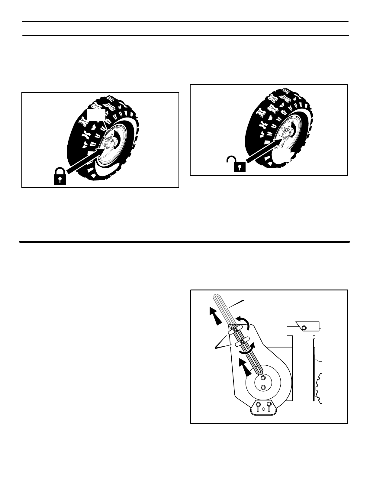
WHEEL LOCK OUT PIN
1. The right wheel is secured tothe axle with a klick pin. This
unit was shipped with this klick pin in the locked position.
(Figure 14).
Klik
Pin
Locked
Position
Figure 14
2. For ease of maneuverability when lighter conditions prevail, remove klick pin from wheel locked position and insert into single wheel drive (unlocked) position
(Figure 15). Make sure that the klick pin is in the single
wheel drive position of the axle only and not through the
locked position.
Single
Wheel Drive
Position
(Unlocked)
Klik
Pin
Figure 15
NOTE: Check tire pressure. See side of tire for maximum
inflation. Do not exceed listed maximum pressure.
HOW TO SET THE DRIFT CUTTERS
(OPTIONAL ACCESSORY ON SOME MODELS)
Drift cutters are used to cut a path through snow deeper than
the auger housing.
1. Loosen the wingnuts that secure the drift cutters to the
auger housing (see Figure 16).
2. Raise the drift cutters to the desired height.
3. Tighten the wingnuts.
MTF--051057L
Drift Cutter
Wingnut
Figure 16
16
Page 17
OPERATION
BEFORE STARTING ENGINE
Check the oil
NOTE: The engine was shipped from the factory filled
with oil. Check the level of the oil. Add oil as needed.
1. Make sure the unit is level.Use a high quality detergent
oil classified “For Service SG, SH, SJ, SL, or higher”.
2. Remove the oil fill cap/dipstick and wipe with a clean
cloth (see Figure 17).
3. Insert the oil fill cap/dipstick and turn clockwise to tighten.
4. Remove the oil fill cap/dipstick and check the oil.
NOTE: Do not check the level of the oil while the
engine runs.
5. If necessary, add oil until the oil reaches the FULL mark
on the oil fill/cap dipstick (see Figure 17). Do not add too
much oil.
6. Tighten the fill cap/dipstick securely each time you check
the oil level.
NOTE: For extreme cold operating conditions of 0F
(−18 C) and below, use a synthetic 5W30 motor oil for
easier starting.
NOTE: S.A.E. 5W30 motor oil may be used to make
starting easier in areas where the temperature is 20 F.
(−7 C) to 0F (−18 C). Synthetic 5W30 is acceptable for
all temperatures. DO NOT mix oil with gasoline.
NOTE: SEE CHART FOR OIL RECOMMENDATION
TYPE OF OILTEMPERATURE
0F (−18 C) and above
0F (−18 C) and below
S.A.E. 5W30
synthetic 5W30
use leaded gasoline. We recommend that fuel stabilizer
be added to the fuel each time that gasoline is added to
the fuel tank.
NOTE: Winter grade gasoline has higher volatility to
improve starting. Be certain container is clean and
free from rust or other foreign particles. Never use
gasoline that may be stale from long periods of
storage in the container.
CAUTION: DO NOT use gasoline containing any
amount of alcohol as it can cause serious damage to
the engine or significantly reduce the performance.
2. Check to make sure that spark plug is tightened securely
into engine and spark plug wire is attached to spark plug.
If torque wrench is available, torque plug to 18−23 ft−lbs.
WARNING: Gasoline is flammable. Always use
caution when handling or storing gasoline. Do
not add gasoline to the fuel tank while snow
blower is running, hot, or when snow blower is in an enclosed area. Keep away from open flame, electrical
sparks and DO NOT SMOKE while filling the fuel tank.
Never fill the fuel tank completely; but fill the fuel tank
to within 1-1/2 inch (3.8 mm) from the top to provide
space for the expansion of the fuel. Always fill fuel tank
outdoors and use a funnel or spout to prevent spilling.
Make sure to wipe up any spilled fuel before starting
the engine.
Store gasoline in a clean, approved container, and keep
the cap in place on the container. Keep gasoline in a
cool well ventilated place; never in the house. Never
buy more than a 30 day supply of gasoline to assure
volatility. Gasoline Is intended to be used as a fuel for
internal combustion engines; therefore, do not use
gasoline for any other purpose. Since many children
like the smell of gasoline, keep it out of their reach because the fumes are dangerous to inhale, as well as being explosive.
SAE VISCOSITY GRADES
5W30
synthetic 5W30
F − 20 0 20 32 40
C −30 −20 −10 0 10
FILL GAS
This engine is certified to operate on gasoline. Exhaust
Emission Control System: EM (Engine Modifications)
1. Fill the fuel tank with fresh, clean, unleaded regular, unleaded premium, or reformulated automotive gasoline
with a minimum of 85 octane along with a fuel stabilizer
(follow instructions on fuel stabilizer package). DO NOT
MTF−051057L
Oil Fill Cap/Dipstick
Fuel Tank
FULL
Figure 17
BEFORE STOPPING THE ENGINE
Run the engine for a few minutes to help dry off any moisture
on the engine.
17
Page 18
OPERATION
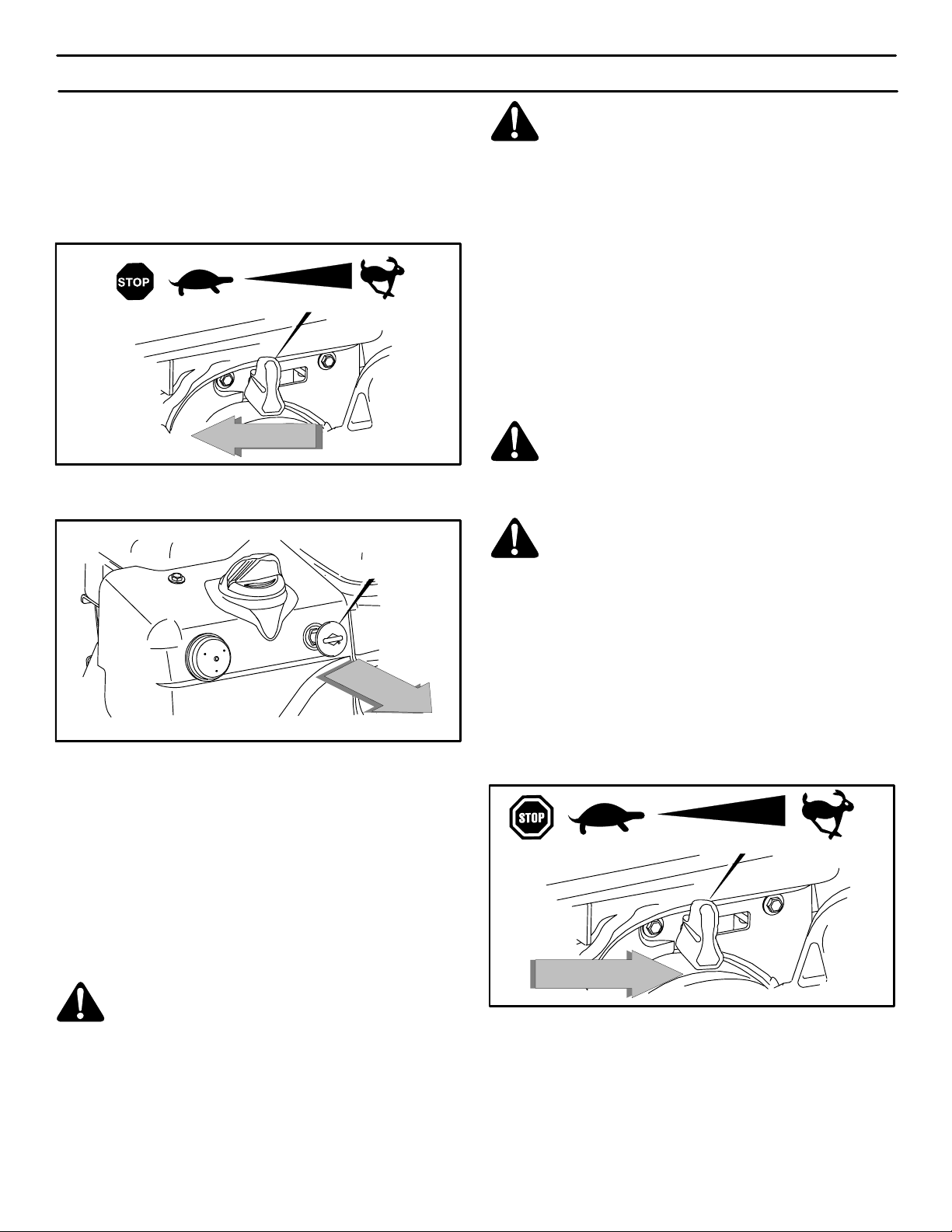
TO STOP ENGINE
CAUTION: To stop the engine, do not move the choke
control to CHOKE position. Backfire or engine damage
can occur.
1. Move throttle control to SLOW, then to STOP
(Figure 18).
Throttle Control
Figure 18
2. Pull out safety/ignition key (Figure 19).
Throttle Control
WARNING: The electric starter is equipped with
a three−wire power cord and plug designed to
operate on 120 volt AC house hold current. The
power cord must be properly grounded at all times to
avoid the possibility of electric shock which can cause
injury to the operator. Follow all instructions carefully
as set forth below:
Make sure your house has a three−wire grounded system. If you are not sure, ask a licensed electrician. If
your house does not have a three−wire grounded system, do not use this electric starter under any condition.
If your house has a three−wire grounded system but a
three hole receptacle is not available to connect the
electric starter, have a three−hole receptacle installed
by a licensed electrician.
WARNING: To connect a 120 volt power cord,
always connect the power cord first to the
switch box located on the engine and then plug
the other end into a three−hole grounded receptacle.
WARNING: To disconnect the power cord, al-
ways unplug the end connected to the three−
hole grounded receptacle first.
Figure 19
TO START ENGINE
Be sure that engine has sufficient oil. Use a high quality
detergent oil classified “For Service SG, SH, SJ, SL, or
higher”.
The snow thrower engine is equipped with a 120 volt A.C.
electric starter and recoil starter. Before starting the engine,
be certain that you have read the following information.
If engine floods, set the choke to the OPEN/RUN position and
crank until the engine starts.
WARNING: Rapid retraction of the starter cord
(kickback) will pull your hand or arm toward the
engine faster than you can let go of the starter
cord.
S When starting the engine, slowly pull the starter cord
until resistance is felt. Then, rapidly pull the starter
cord.
S Make sure components; such as impellors, pulleys
or sprockets, are securely attached.
MTF−051057L
COLD ENGINE START
(Engine has not been run recently.)
1. Be sure auger drive clutch lever and traction drive clutch
lever are in the disengaged (RELEASED) position.
2. Move throttle control to “FAST” position. Operate the engine with the throttle control in FAST position (Figure 20).
Before engaging auger drive clutch lever allow engine to
idle for five minutes to allow engine oil to warm . Failure
to allow engine oil to warm can cause damage to engine.
Throttle Control
Figure 20
3. Insert key into ignition slot. Make sure it snaps into place
(Figure 21). Do not turn key.
4. Rotate choke knob to the CHOKE position.
5. Push the primer button as follows:
Above 50° F (10° C), DO NOT PRIME.
From 50° F (10° C) to 15°F (−10° C), PUSH TWO TIMES.
Below 15° F (−10° C), PUSH FOUR TIMES.
18
Page 19

OPERATION
NOTE: Cover the vent hole when as you push the
primer. Remove your finger from the primer vent
hole between pushes.
Choke Knob
Ignition Key
Connect
Power Cord
Starter Button
Figure 23
Primer Button
Figure 21
6. (RECOIL START) Slowly pull the recoil starter handle
until resistance is felt and then pull repidly to start the engine (Figure 22). Do not allow the recoil starter handle
to snap back. Slowly return the recoil starter handle.
Recoil Starter Handle
Figure 22
7. (ELECTRIC START) Connect the power cord to the en-
gine and depress the starter button (Figure 23). To prolong the life of the starter, do not crank for more than 5
seconds at a time. Wait one minute between starts to allow the starter motor to cool.
8. If the engine does not start in 5 or 6 tries, See Difficult
Starting in the “Troubleshooting Table”.
9. As engine warms up move choke lever to “1/2 choke”
position. When engine does not run smoothly, move
choke lever to the off position.
NOTE: Allow the engine to warm up for several
minutes before blowing snow in temperatures below
0°F (−18 C).
10. (Electric Start) First disconnect power cord from receptacle. Then, disconnect the power cord from the switch
box.
If after following the preceding instructions, your engine fails
to start, have the engine checked by a John Deere/Frontier
dealer.
NOTE: Do not lose the safety/ignition key. Keep the
safety/ignition key is a safe place. The engine will not
start without the safety/ignition key.
WARM ENGINE START (RECOIL STARTER)
If restarting a warm engine after a short shutdown, leave
choke at “OFF” and do not push the primer button. If the
engine fails to start, follow the Cold Start instructions.
MTF−051057L
19
Page 20

OPERATION
FROZEN STARTER
If the starter is frozen and will not turn engine:
1. Pull as much rope out of the starter as possible.
2. Release the starter handle and let it snap back against
the starter. Repeat until the engine starts.
Warm engines will cause condensation in cold weather. To
help prevent possible freeze−up of recoil starter and engine
controls, proceed as follows after each snow removal job.
1. With engine off, allow engine to cool for several minutes.
2. Pull starter rope very slowly until resistance is felt, then
stop. Allow the starter rope to recoil. Repeat three times.
3. With the engine not running, wipe all snow and moisture
from the carburetor cover in area of control levers. Also
move choke knob and starter handle several times.
4. With engine not running, wipe all snow and moisture from
carburetor cover in area of control levers. Also move
control levers backward and forward several times.
WARNING: Never run engine indoors or in enclosed, poorly ventilated areas. Engine exhaust
contains CARBON MONOXIDE, AN ODORLESS
AND DEADLY GAS. Keep hands, feet, hair and loose
clothing away from any moving parts on engine and
snow thrower.
S Engine parts, especially the muffler, become ex-
tremely hot. Severe thermal burns can occur on contact. Allow the engine to cool before touching.
S Never allow children to operate the snow thrower.
Never allow adults to operate the snow blower without proper instruction.
S Keep the area of operation clear of all persons, partic-
ularly small children and pets.
S Never leave the snow blower unattended while the
engine is running. Anyone operating the engine or
equipment must carefully read and understand the
operating instructions.
IMPORTANT: After each use of the snow blower, stop the
engine, remove the safetey/ignition key, remove all
accumulated snow from the snow blower and wipe
clean. Store the snow blower in a protected area.
NOTE: Never cover snow blower while engine and
exhaust area are still warm.
HOW TO CLEAR
A CLOGGED DISCHARGE CHUTE
WARNING: Hand contact with the rotating impeller inside the discharge chute is the most
common cause of injury associated with snow
blowers. NEVER USE YOUR HAND TO CLEAN OUT
THE DISCHARGE CHUTE.
To Clear The Chute:
S SHUT OFF THE ENGINE!
S Wait 10 seconds to be sure that the impeller blades
have stopped rotating.
S Always use a clean-out tool, not your hands.
A clean-out tool is attached to either the handle or the top of
the auger housing (see Figure 24). Use the clean-out tool to
remove snow from the auger housing.
How To Use The Clean-Out Tool
Release the auger drive lever.
Pull out the safety key.
Disconnect spark plug wire.
Do not place your hands in the auger or discharge
chute. Use a clean-out tool to remove snow or debris.
WARNING: Blockage must be cleared only after
shutting off the snow blower and only with a
clean-out tool, not by hand.
Clean-out Tool
Figure 24
MTF−051057L
20
Page 21

OPERATING TIPS
OPERATION
1. For optimum snow blower efficiency, adjust ground
speed, not the throttle. REMEMBER − if the wheels slip,
forward speed will be reduced. The engine is designed
to deliver optimum performance at full throttle and must
be run at this power setting at all times.
2. Most efficient snowblowing is accomplished when snow
is removed immediately after it falls.
3. For complete snow removal, slightly overlap each swath
previously taken.
4. Snow should be discharged downwind whenever possible.
5. For normal usage, set the skids one−eighth inch (3 mm)
below the scraper bar. For extremely hard−packed snow
surfaces, the skids may be adjusted upward to insure
cleaning efficiency.
6. On gravel or crushed rock surfaces, the skids should be
set at 1−1/4 inch (32 mm) below the scraper bar (see To
Adjust Skid Height, in the Adjustment/Repair section in
this manual). Rocks and gravel must not be picked up
and thrown by the machine.
7. After the snowblowing job has been completed, allow the
engine to idle for a few minutes, to melt snow and ice accumulated on the engine.
8. Clean the snow thrower thoroughly after each use.
9. Remove ice and snow accumulation and all debris from
the entire snow thrower, and flush with water (if possible)
to remove all salt or other chemicals. Wipe snow thrower
dry.
10. Before starting snow blower, always inspect augers and
impeller for ice accumulation and/or debris, which could
result in snow blower damage.
11. Check oil level before every start. Make sure the oil is at
the FULL mark on the oil fill cap/dipstick.
MTF−051057L
21
Page 22

SERVICE RECOMMENDATIONS
W
R
O
G
SERVICE RECOMMENDATIONS
PROCEDURE
S
Tighten all screws and nuts
N
Check Traction Clutch
O
Cable Adjustment
(See Cable Adjustment)
W
T
Check Auger clutch Cable
Adjustment
H
(See Cable Adjustment)
Adjust Drive Belts
O
W
Lubricate Chains and
Hex Shaft
E
R
Lubricate Auger Shaft (See
Shear Bolt Replacement)
E
Oil, Check
N
G
I
N
Oil, Change
E
FIRST
2
HOUR
BEFORE
EACH
USE
OFTEN
EVERY
5
HOURS
EVERY
10
HOURS
EVERY
25
HOURS
BEGINNING
√ √
√ √
√ √
√
√ √
√
√ √
√
√ √
EACH
SEASON
√
√
√
BEFORE
STORAGE
√
√
The warranty on this snowthrower does not cover items that
have been subjected to operator abuse or negligence. To receive full value from the warranty, operator must maintain
snowthrower as instructed in this manual. The following Ser-
vice Recommendations is supplied to assist operator to
properly maintain snowthrower. This is a check list only. Adjustment referred to will be found in the MAINTENANCE section of this manual.
MTF−051057L
AFTER EACH USE
1. Check for any loose or damaged parts.
2. Tighten any loose fasteners.
3. Check and maintain the auger.
4. After each use, remove all snow and slush off the snowthrower to prevent freezing of auger or controls.
5. Check controls to make sure they are functioning properly.
6. If any parts are worn or damaged, replace immediately.
22
Page 23

MAINTENANCE
Some adjustments will need to be made periodically to
properly maintain your snowthrower.
All adjustments in the MAINTENANCE section of this manual
should be checked at least once each season.
SNOWTHROWER
The following adjustment should be performed more than
once each season.
Auger and Traction Drive Belts should be adjusted after the
first 2 to 4 hours of use, again about mid−season and twice
each season thereafter (See To Adjust Belts paragraph in the
MAINTENANCE section).
AS REQUIRED
Auger Gear Box
The auger gear box is lubricated at the factory and should not
require additional lubrication.
If for some reason the lubricant should leak out, or if the auger
gear box has been serviced, add Lubriplate GR132 Grease
or “Deere Multi−Purpose Lithium Grease”. Maximum 3−1/4
ounces, (92 grams) should be used.
Remove filler plug D (Figure 25 and Figure 26), once a year.
If grease is visible, do not add. If grease is not visible, use a
piece of fine wire, like a dipstick to check if there is grease in
the gear box. Mobilux EP1 and Shell Aldania EP1 are
suitable equivalents.
Figure 25D
Filler
Plug
Figure 26
LUBRICATION
Bearings and bushings
All bearings and bushings are lifetime lubricated and require
no maintenance.
Hex shaft and chains
For storage, the hex shaft should be wiped with a cloth lightly
moistened with motor oil to prevent rusting (see Figure 28).
For storage, the chains should be lubricated with a chain type
lube. (see Figure 28).
NOTE: Any greasing or oiling of the above mentioned
components can cause contamination of the rubber
friction wheel. If the disc drive plate or friction wheel
come in contact with grease or oil damage to rubber
friction wheel will result .
MTF−051057L
If grease or oil comes into contact with the disc drive plate or
friction wheel, make sure to clean plate and wheel thoroughly
with a alcohol base solvent.
LUBRICATION − EVERY 10 HOURS
1. Auger Shaft − Using a hand grease gun, lubricate the
auger shaft zerk fittings (A) every ten (10) operating
hours. Each time a shear bolt is replaced, the auger shaft
MUST be greased (Figure 25). (See To Replace Auger
Shear Bolt in the MAINTENANCE section).
2. For storage or when replacing shear bolts, remove shear
bolts and lubricate auger shaft zerks. Rotate augers several times on the shaft and reinstall the shear bolts.
23
Page 24

MAINTENANCE
LUBRICATION − EVERY 25 HOURS
Chute Rotation Gear
Lubricate the chute rotation gear with automotive type oil.
(see Figure 27).
Chains
1. Position speed selector lever in first (1) forward gear.
2. Stand the snowthrower up on the auger housing end.
NOTE: When the crank case if filled with oil, do not
leave the snowthrower standing up on the auger
housing for an extended period of time.
3. Remove the bottom panel.
Chute Rotation Gear
Figure 27
4. Lubricate the chains with a chain type lubricant.
5. Wipe the hexshaft and sprockets with 5W30 motor oil.
NOTE: Clean all excess grease or oil found on the
rubber friction wheel or the disc drive plate.
CAUTION: Do not allow grease or oil to contact the
rubber friction wheel or the disc drive plate.
6. Install the bottom panel.
Chain
Hexshaft− wipe with 5W30 motor oil before storage and at the beginning of each
season
Chain
WARNING: If the disc drive plate
or rubber friction wheel come in
contact with grease or oil
damage to rubber friction wheel
will result .
If grease or oil come in contact with
the disc drive plate or friction wheel,
make sure to clean the plate and
wheel thoroughly with a alcohol base
solvent.
MTF−051057L
Figure 28
24
Page 25

MAINTENANCE
ENGINE
Check Crankcase Oil Level before starting engine and after
each 5 hours of continuous use (see Figure 29). Add proper
motor oil as required.
NOTE: Overfilling the engine can affect performance.
Tighten the oil fill cap securely to prevent leakage.
Change Oil every 25 hours of operation or at least once a
year, even if the snowthrower is not used for twenty−five
hours. Use a clean, high quality detergent oil. Fill the crank
case to FULL line on dipstick (see Figure 29). Be sure original
container is marked: A.P.I. service “SF” or higher. Do not use
SAE10W40 oil (as it may not provide proper lubrication). See
Chart for oil recommendations.
To Drain Oil − Position snowthrower so that the oil drain plug
is lowest point on engine. Remove oil drain plug and oil fill cap
and drain oil into a suitable container (Figure 30).
NOTE: Oil will drain more freely when warm.
Replace oil drain plug and tighten securely. Refill crank case
with proper motor oil or as indicated in the preceding
paragraphs of this section.
Oil Fill Cap/Dipstick
FULL
Figure 29
TYPE OF OILTEMPERATURE
0F (−18 C) and above
0F (−18 C) and below
S.A.E. 5W30
synthetic 0W30
SAE VISCOSITY GRADES
5W30
synthetic 0W30
F − 20 0 20 32 40
C −30 −20 −10 0 10
Oil Drain Plug
Figure 30
MTF−051057L
25
Page 26

MAINTENANCE
WARNING: Always turn unit off, remove ignition key and disconnect the spark plug wire before making any repairs or adjustments.
AUGER HOUSING HEIGHT ADJUSTMENT
TO ADJUST SCRAPER BAR
After considerable use, the metal scraper bar will have a
definite wear pattern. The scraper bar in conjunction with the
skids should always be adjusted to allow one−eighth of an
inch (3 mm) between the scraper bar and the sidewalk or
area to be cleaned.
To adjust the scraper bar, proceed as follows:
1. Position the snowthrower on a level surface.
2. Loosen the carriage bolts and nuts securing the scraper
bar to the auger housing.
3. Adjust the scraper bar to the proper position. Tighten the
carriage bolts and nuts, insuring that the scraper bar is
parallel with the working surface.
4. For extended operation, the scraper bar may be reversed. If the scraper bar must be replaced because of
wear, remove the carriage bolts and nuts and install a
new scraper bar.
TO ADJUST SKID HEIGHT
This snowthrower is equipped with two height adjust skids,
secured to the outside of the auger housing. These elevate
the front of the snowthrower.
When removing snow from a hard surface area such as a
paved driveway or walk, adjust the skids up to bring the front
of the snowthrower down.
When removing snow from rock or uneven construction,
raise the front of the snowthrower by moving the skids down.
This will help to prevent rocks and other debris from being
picked up and thrown by the augers.
To adjust skids, proceed as follows:
1. Place a block (equal to height from ground desired) under scraper bar near but not under skid.
2. Loosen skid mounting nuts (Figure 31) and push the skid
down until it touches the ground. Retighten mounting
nuts.
3. Set skid on other side at same height.
NOTE: Make sure that snowthrower is set at same height
on both sides.
WARNING: Be certain to maintain proper
ground clearance for your particular area to be
cleared. Objects such as gravel, rocks or other
debris, if struck by the impeller, may be thrown with
sufficient force to cause personal injury, property damage or damage to the snowthrower.
Height Adjust Skid
Skid Mounting Nuts
Figure 31
MTF−051057L
26
Page 27

MAINTENANCE
BELT ADJUSTMENT
Traction Drive Belt
The traction drive belt has constant spring pressure and does
not require an adjustment. If the traction drive belt is slipping,
replace the belt. See “How To Replace The Belts” in the
Maintenance section.
Auger Drive Belt
If your snowthrower will not discharge snow, check the
control cable adjustment. If it is correct, then check the
condition of the auger drive belt. If it is damaged or loose,
replace it (see Belt Replacement in this section of the
manual).
1. Disconnect spark plug wire.
2. Remove screw from belt cover. Remove belt cover
(see Figure 32).
3. Loosen nut on auger idler pulley and move auger idler
pulley towards belt about 1/8 inch (3 mm) (see
Figure 36).
4. Tighten nut.
5. Have someone engage auger drive clutch. Check tension on belt (opposite idler pulley). Belt should deflect
about 1/2 inch (12.5 mm) with moderate pressure
Figure 33). You may have to move idler pulley more than
once to obtain the correct tension.
Idler
Pulley
Engaged
Screw
Belt Cover
Figure 32
Auger
Drive
Engine
Pulley
1/2 inch
(12.5mm)
Deflection
6. Reinstall belt cover.
7. Whenever belts are adjusted or replaced, the cables will
need to be adjusted. (See Cable Adjustment in this section of the manual).
8. Attach the spark plug wire.
MTF−051057L
Impeller
Pulley
Figure 33
27
Page 28

HOW TO REPLACE THE BELTS
MAINTENANCE
The drive belts are of special construction and must be
replaced with original factory replacement belts available
from your nearest authorized service center.
Some steps require the assistance of a second person.
How To Remove the Auger Drive Belt
If the auger drive belt is damaged, the snow thrower will not
discharge snow. Replace the damaged belt as follows.
1. Disconnect the spark plug wire.
2. Loosen the bolts on each side of the bottom panel (see
Figure 34).
3. Remove the bottom panel.
4. Remove screw from belt cover. Remove the belt cover
(see Figure 32).
5. Loosen the belt guide. Pull the belt guide away from the
auger drive pulley (see Figure 36).
6. Pull the idler pulley away from the auger drive belt and
slip the auger drive belt off of the idler pulley.
7. Remove the auger drive belt from the engine pulley. To
remove the auger drive belt, the engine pulley may
have to be partially rotated.
8. Remove the top four bolts that hold together the auger
housing and the motor box. Loosen the bottom two
bolts. The auger housing and the motor box can now
be split apart for removal of the belt (see Figure 35).
16. Install the belt cover. Tighten screw (See Figure 32).
17. Check the adjustment of the cables. See “How To Check
And Adjust The Cables” in the Maintenance section.
18. Install the bottom panel (see Figure 34).
19. Tighten the bolts on each side of the bottom panel.
20. Connect the spark plug wire.
Bolt
Bolt
Bottom Panel
Auger Housing
Figure 34
9. Remove the old auger drive belt from the auger drive
pulley . Replace the auger drive belt with an original
factory replacement belt available from an authorized
service center (see Figure 36).
10. Install the new auger drive belt onto the auger drive
pulley.
NOTE: To assemble the auger housing to the motor box, have someone hold the auger clutch lever
in the ENGAGED position. This will move the idler
arm and pulley enough to allow the auger drive
pulley to move back into position.
11. Assemble the auger housing to the motor box with the
four bolts that were removed in step 8. Tighten the bottom two bolts.
12. Install the auger drive belt onto the engine pulley.
13. Slip the auger drive belt under the idler pulley.
14. Adjust the auger drive belt. See “How To Adjust The Auger Drive Belt” in the Maintenance section.
15. Adjust the belt guide. See “How To Adjust The Belt
Guide” in the Maintenance section.
MTF−051057L
28
Motor Box
Remove
Bolts
Loosen
Bolts
Auger
Housing
Figure 35
Page 29

Engine Pulley
Traction Drive Idler Pulley
MAINTENANCE
Traction Drive Belt
Belt Guide
Auger Drive Pulley
E−Ring
Swing Plate Axle Rod
Idler Pulley
Auger Drive Belt
Traction Drive Spring
Traction Drive Belt
Traction Drive Pulley
Engine Pulley
Figure 36
MTF−051057L
29
Page 30

How To Remove the Traction Drive Belt
MAINTENANCE
If the snow thrower will not move forward, check the traction
drive belt for wear or damage. If the traction drive belt is worn
or damaged, replace the belt as follows.
1. Disconnect the spark plug wire.
2. Remove the auger drive belt. See “How To Remove The
Auger Drive Belt” in the Maintenance section.
3. Remove the e−ring from one end of the swing plate
axle rod. Remove the swing plate axle rod to allow the
the swing plate to pivot forward (see Figure 36).
4. Remove the traction drive spring.
5. Remove the old traction drive belt from the traction
drive pulley and from the engine pulley. Replace the
traction drive belt with an original factory replacement
belt available from an authorized service center.
6. Install the new traction drive belt onto the traction
drive pulley and onto engine pulley.
11. Install and adjust the auger drive belt. See “How To Remove The Auger Drive Belt” in the Maintenance section.
12. Adjust the belt guide. See “How To Adjust The Belt
Guide” in the Maintenance section.
13. Install the bottom panel (see Figure 34).
14. Tighten the bolts on each side of the bottom panel.
15. Install the belt cover. Tighten screw (see Figure 32).
16. Check the adjustment of the cables. See “How To Check
And Adjust The Cables” in the Maintenance section.
17. Connect the spark plug wire.
7. Make sure the traction drive idler pulley is properly
aligned with the traction drive belt.
8. Attach the traction drive spring.
9. Install the swing plate axle rod and secure with the e−
ring removed earlier.
10. The bottom of the swing plate must be positioned between the alignment tabs. Make sure the swing plate
is properly secured (see Figure 37).
NOTE: If the drive will not engage after the traction
drive belt has been replaced, then check to make
sure that the swing plate is positioned between the
alignment tabs.
Alignment Tabs
Swing Plate
Figure 37
MTF−051057L
30
Page 31

BELT GUIDE ADJUSTMENT
1. Remove spark plug wire.
2. Have someone engage auger drive.
MAINTENANCE
3. Measure the distance between the belt guide and belt.
The distance should be 1/8 inch (3.175 mm) for guide.
See Figure 38.
4. If adjustment is necessary, loosen belt guide mounting
bolt. Move belt guide to the correct position. Tighten
mounting bolt.
5. Reinstall belt cover.
6. Reconnect spark plug wire.
HOW TO CHECK AND ADJUST THE CABLES
The cables are adjusted at the factory and no adjustment
should be necessary. If the cables have become stretched
or are sagging adjustment will be necessary.
Whenever belts are adjusted or replaced, the cables will
need to be adjusted.
1. Move clutch lever to the full forward position (just contacting plastic bumper). Holding cable tight, note position of fitting to hole in clutch lever.
2. The center of the “Z” fitting should be between the centre
and top of the hole in the clutch lever. Adjust either the
auger drive cable or the traction drive cable as follows.
Auger Idler
Pulley Engaged
Square
End
Belt Guide
1/8 Inch (3.175 mm)
Figure 38
Auger Drive Cable Adjustment
WARNING: Drain the gasoline outdoors, away
from fire or flame.
1. Remove the gas from the gas tank. Stand the snow
thrower up on the front end of the auger housing.
2. Push cable through spring to expose the threaded portion of the cable (see Figure 39).
3. Hold square end of threaded portion with pliers and adjust locknut in or out until correct adjustment is reached.
Pull cable back through spring and connect cable.
Cable
Spring
Locknut
Figure 39
MTF−051057L
31
Page 32

MAINTENANCE
Traction Drive Cable Adjustment
WARNING: Drain the gasoline outdoors, away
from fire or flame.
1. Remove the gas from the gas tank. Stand the snow
thrower up on the front end of the auger housing.
2. Loosen the bolts on each side of the bottom panel (see
Figure 40).
3. Remove the bottom panel.
4. Slide the cable boot off the cable adjustment bracket
(see Figure 41).
5. Push the bottom of the traction drive cable through the
cable adjustment bracket until the “Z” hook can be re-
moved.
6. Remove the “Z” hook from the cable adjustment
bracket. Move the “Z” hook down to the next adjustment hole.
7. Pull the traction drive cable up through the cable ad-
justment bracket.
8. Put the cable boot over the cable adjustment bracket.
9. To check the adjustment, depress the drive lever and
check the length of the drive spring (see Figure 42). In
correct adjustment, the length of the drive spring is
minimum 3 inches (76 mm.)
maximum 3-3/8 inches (85 mm.).
10. Install the bottom panel (see Figure 40).
11. Tighten the bolts on each side of the bottom panel.
Cable Adjustment Bracket
“A”
Traction Drive Cable
Cable Boot
“Z” Hook
Figure 41
Bolt
Bolt
Bottom Panel
Auger Housing
Figure 40
Drive Spring
Figure 42
MTF−051057L
32
Page 33

MAINTENANCE
HOW TO ADJUST OR REPLACE
THE FRICTION WHEEL
How To Check The Friction Wheel
If the snow thrower will not move forward, check the traction
drive belt, the traction drive cable or the friction wheel. If the
friction wheel is worn or damaged, it must be replaced. See
“How To Replace the Friction Wheel” in this section. If the
friction wheel is not worn or damaged, check as follows.
1. Remove the gas from the gas tank. Stand the snow
thrower up on the front end of the auger housing (see
Figure 43).
WARNING: Drain the gasoline outdoors, away
from fire or flame.
2. Disconnect the spark plug wire.
3. Loosen the bolts on each side of the bottom panel (see
Figure 43).
5. Tighten the jam nut.
6. Install the bottom panel (see Figure 43).
7. Tighten the bolts on each side of the bottom panel.
Bolt
Bolt
Bottom Panel
Auger Housing
Figure 43
4. Remove the bottom panel.
5. Position the shift speed lever in the lowest forward
speed.
6. Note the position of the friction wheel (see Figure 44).
The correct distance “A” from the right side of the fric-
tion wheel to the outside of the motorbox is as follows:
Tire Size Distance “A”
12 and 13 inch 4-1/8” (10.5 cm.)
16 inch 4-5/16” (10.95 cm.)
If the friction wheel is not in the correct position, adjust
as follows.
How To Adjust The Friction Wheel
1. Position the shift speed lever in the lowest forward
speed.
2. Loosen hex jam nut on speed select rod. Remove ball
joint from shifter rod (see Figure 45).
3. Move the friction wheel to the correct position (see
Figure 44).
4. Turn the adaptor until the ball joint is aligned with the
mounting hole in the shifter rod (see Figure 45). When
aligned, attach the ball joint to the shifter rod.
MTF−051057L
33
Speed Select Rod
Jam Nut
Adaptor
“A”
Figure 44
Shifter Rod
Ball Joint
Fasteners
Figure 45
Page 34

MAINTENANCE
How To Replace The Friction Wheel
If the friction wheel is worn or damaged, the snow thrower will
not move forward. The friction wheel must be replaced as
follows.
1. Remove the gas from the gas tank. Stand the snow
thrower up on the front end of the auger housing (4).
(see Figure 43).
WARNING: Drain the gasoline outdoors, away
from fire or flame.
2. Disconnect the spark plug wire.
Axle
Drive
Sprocket
Chain
3. Remove the fasteners that secure the left wheel. Remove the left wheel from the axle (see Figure 46)
4. Loosen the bolts on each side of the bottom panel.
5. Remove the bottom panel.
Axle Bolt
Bottom
Panel
Bolt
Wheel
Figure 46
Figure 47
8. Remove the four bolts that hold the bearings on each
side of the hex shaft (see Figure 48).
9. Remove the hex shaft and bearings.
NOTE: Take special note of the position of the
washers on the hex shaft.
Bearings
Hex Shaft
Bolts
Bolts
6. Remove the fasteners that secure the drive sprocket to
the axle (see Figure 47).
7. Remove the right wheel, axle, and drive sprocket.
MTF−051057L
Figure 48
34
Page 35

MAINTENANCE
10. Remove the three fasteners that hold the friction wheel
to the hub (see Figure 49).
11. Remove the friction wheel from the hub. Slip the fric-
tion wheel off the hex shaft.
12. Assemble the new friction wheel onto hub with the fas-
teners removed earlier.
Washer
Bearings
Fasteners
Hex Shaft
Hub
Friction
Wheel
Fasteners
Figure 49
13. Install the hex shaft and bearings with the four bolts removed earlier (see Figure 50).
Make sure the washers are properly installed in the
original position. Also, make sure the two washers
are properly aligned with the actuator arms.
Actuator Arms
Bearings
Hex Shaft
Washer
Washer
Washer
Figure 50
15. Install the right wheel, axle, and drive sprocket with the
fasteners removed earlier. Install the chain onto the
drive sprocket (see Figure 47).
16. Check the adjustment of the friction wheel. See “How To
Adjust The Friction Wheel” in this section.
17. Make sure the friction wheel and the disc drive plate are
free from grease or oil.
18. Install the bottom panel (see Figure 46).
19. Tighten the bolts on each side of the bottom panel.
20. Install the left wheel to the axle with the fasteners removed earlier.
14. Make sure the hex shaft turns freely.
MTF−051057L
21. Connect the spark plug wire.
35
Page 36

MAINTENANCE
HOW TO REMOVE THE SNOW HOOD
To access the spark plug, the snow hood must be removed
as follows:
1. Remove the choke control knob (see Figure 51).
2. Remove the ON/OFF key.
3. Remove the four mounting screws.
4. Slowly remove the snow hood (see Figure 52). Make
sure that the primer button hose and the ignition wire are
not disconnected.
5. To install the snow hood, first make sure that the primer
button hose and the ignition wire are connected.
6. Mount the snow hood to the engine and secure with the
four mounting screws (see Figure 53).
Snow Hood
Figure 52
7. Align the tab on the choke control knob with the slot in the
snow hood (see Figure 54).
8. Connect the choke control knob with the choke shaft.
Make sure the choke control knob is properly installed.
If the choke control knob is not installed correctly, the
choke will not operate.
Choke Control Knob
Screws
ON/OFF
Key
Snow Hood
Screws
Figure 51
Slot
Snow Hood
Ta b
Carburetor
Figure 53
Choke Control
Knob
MTF−051057L
Figure 54
36
Page 37

MAINTENANCE
AUGER SHEAR BOLT REPLACEMENT
The augers are secured to the auger shaft with special bolts
that are designed to break if an object becomes lodged in the
auger housing. Use of a harder bolt will reduce the protection
provided by the shear bolt. To replace a broken shear bolt,
proceed as follows:
WARNING: To insure safety and performance
levels, only original replacement shear bolts
should be used.
1. Move throttle to STOP, disengage all controls, disconnect the spark plug lead wire, and insure all moving parts
have stopped.
2. Lubricate the auger shaft zerk fittings (see Lubrication
Points in the Maintenance section of this manual).
3. Align the hole in the auger with the hole in the auger shaft.
Install new shear bolt, spacer and locknut found in the
toolbox located on the belt cover (See Figure 55).
NOTE: The spacer fits into the larger hole in the auger
tube.
Shear Pin
Spacer
Locknut
Figure 55
TO ADJUST OR REPLACE THE SPARK PLUG
Check the spark plug every twenty−five (25) hours. Re-
place the spark plug if the electrodes are pitted or burned
or if the porcelain is cracked.
1. Clean spark plug and reset gap periodically.
2. Clean area around spark plug base before removal, to
prevent dirt from entering engine.
3. Replace spark plug if electrodes are pitted or burned or
if porcelain is cracked.
4. Clean spark plug by carefully scraping electrodes (do not
sandblast or use wire brush).
5. Be sure spark plug is clean and free of foreign material.
Check electrodes gap with a wire feeler gauge and reset
gap to 0.030” (0.76 mm) if necessary. If a new spark plug
is needed, refer to Engine Repair Parts section of this
manual for proper replacement spark plug.
6. Before installing spark plug, coat threads lightly with
graphite grease to insure easy removal.
7. Tighten plug firmly into engine. If torque wrench is available, torque plug to 18−23 ft−lbs.
.030” (0.76 mm) Gap
Figure 56
MTF−051057L
37
Page 38

STORAGE
OFF SEASON STORAGE
WARNING: Never store the engine, with fuel in
the tank, indoors or in a poor ventilated enclo-
sure where fuel fumes could reach an open
flame, spark or pilot light as on a furnace, water heater,
clothes dryer, etc.
Handle gasoline carefully. It is highly flammable and
careless use could result In serious fire damage to your
person and /or property.
Drain fuel into approved containers outdoors, away
from open flame.
If the snowthrower is to be stored for thirty (30) days or more
at the end of the snow season, the following steps are
recommended to prepare your snowthrower for storage.
NOTE: Gasoline must be removed or treated to prevent
gum deposits from forming in the tank, filter, hose, and
carburetor during storage.
1. To remove gasoline, run engine until tank is empty and
engine stops.
If you do not want to remove the gasoline, add fuel stabilizer
to any gasoline left in the tank to minimize gum deposits and
acids. If the tank is almost empty, mix stabilizer with fresh
gasoline in a separate container and add some to the tank.
ALWAYS FOLLOW INSTRUCTIONS ON STABILIZER
CONTAINER. THEN RUN ENGINE AT LEAST 10 MINUTES
AFTER STABILIZER IS ADDED TO ALLOW MIXTURE TO
REACH CARBURETOR. STORE SNOWTHROWER IN
SAFE PLACE.
2. You can help keep your engine (4−cycles only) in good
operating condition by changing oil before storage.
3. Lubricating the piston/cylinder area. This can be done by
first removing the spark plug and squirting clean engine
oil into the spark plug hole. Then cover the spark plug
hole with a rag to absorb oil spray. Next, rotate the engine
by pulling the starter two or three times. Finally, reinstall
spark plug and attach spark plug wire.
4. Thoroughly clean the snowthrower.
5. Lubricate all lubrication points (see “Lubrication“ in the
Maintenance s ection).
6. Insure that all nuts, bolts, and screws are securely fastened. Inspect all visible moving parts for damage,
breakage, and wear. Replace if necessary.
7. Touch up all rusted or chipped paint surfaces; sand lightly
before painting.
8. Cover the bare metal parts of the snowthrower housing
auger, and the impeller with rust preventative.
9. If possible, store your snowthrower indoors and cover it
to give protection from dust and dirt.
10. On models with folding handles, loosen the knobs that
secure the upper handle. Rotate the upper handle back.
11. If the machine must be stored outdoors, block up the snowthrower and insure the entire machine is off the
ground. Cover the snowthrower with a heavy tarpaulin.
REMOVING THE SNOWTHROWER FROM
STORAGE
When removing the snowthrower from storage, follow the
steps below.
1. Put the upper handle in the operating position, tighten the
knobs that secure the upper handle.
2. Fill the fuel tank with a fresh fuel.
3. Check the spark plug. Make sure the gap is correct. If the
spark plug is worn or damaged, replace before using.
4. Make sure all fasteners are tight.
5. Make sure all guards, shields, and covers are in place.
6. Make sure all adjustments are correct.
MTF−051057L
38
Page 39

TROUBLE SHOOTING CHART
PROBLEM LOOK FOR REMEDY
Difficult starting Defective spark plug. Replace defective spark plug.
Engine runs erratically Blocked fuel line. Clean fuel line.
Empty gas tank. Check fuel supply,
Stale gasoline. Add fresh gasoline with fuel stabilizer.
Water or dirt in fuel system. Remove carburetor bowl to drain fuel tank. Refill
with fresh fuel. CAUTION: Do not remove
carburetor bowl when the engine is hot.
Engine stalls Unit running on CHOKE. Set choke lever to RUN position.
Loss of power Gas cap vent hole is plugged. Remove ice and snow from cap. Be sure vent
hole is clear.
Excessive vibration Loose parts or damaged impeller. Stop engine immediately and remove spark plug
wire. Tighten all bolts and make all necessary
repairs. If vibration continues, have the unit
serviced by a competent repairman.
Unit fails to propel
itself
Unit fails to discharge
snow
Drive belt loose or damaged. Replace drive belt. Refer to Drive Belt
Replacement in the Maintenance section of this
manual.
Incorrect adjustment of traction drive
cable.
Worn or damaged friction disc. Replace friction disc. Refer to Friction Wheel
Auger drive belt loose or damaged. Replace or adjust auger drive belt. Refer to Drive
Auger control cable not adjusted
correctly.
Broken shear bolt. Replace shear bolt. Refer to Auger Shear Bolt
Discharge chute clogged. Stop engine immediately and disconnect spark
Adjust traction drive cable. Refer to Cable
Adjustment in the Maintenance section of this
manual.
Replacement in the Maintenance section of this
manual.
Belt Replacement and Drive Belt Adjustment in
the Maintenance section of this manual.
Adjust auger control cable. Refer to Cable
Adjustment in the Maintenance section of this
manual.
Replacement in the Maintenance section of this
manual.
plug wire. Refer to the first Warning in
Snowthrower Operation in the Operation
section of this manual. Clean discharge chute
and inside of auger housing.
Foreign object lodged in auger. Stop engine immediately and disconnect spark
plug wire. Refer to the third Warning in
Snowthrower Operation in the Operation
section of this manual. Remove object from
auger.
Identifying Your Snowthrower
Your new snowthrower has two (2) identifying numbers: (1) unit model number: (2) unit serial number. The two preceding
numbers are required to insure that the proper replacement parts are obtained when required. If you have any questions
concerning parts, service, or technical data, contact your nearest John Deere/Frontier dealer.
For complete warranty information refer to the warranty in the Owner’s Information section of this manual.
MTF−051057L
39
Page 40

REPLACEMENT PARTS
WE RECOMMEND JOHN DEERE/FRONTIER quality
parts and lubricants available at your John Deere/Frontier
dealer.
PART NUMBERS MAY CHANGE. When you order replacement parts, use the part numbers listed below and on
the following pages. If a part number changes, your John
Deere/Frontier dealer will have the latest part number.
WHEN YOU ORDER PARTS, your John Deere/Frontier
dealer must have your snowthrower model and serial number and your engine model number. This is the model and
serial number that you recorded in the “Owner’s Information” section of this Owner’s Manual.
QUICK REFERENCE PART NUMBERS
The following is a list of replacement parts that you may
need for routine service and maintenance. If you do not
see the replacement part you need in the following chart,
then check the full list of replacement part illustrations following this page.
ITEM PART NUMBER *
Belt, Drive MT579932
Belt, Auger MT585416
Scraper Blade
Spark Plug Champion RC12YC
* Part Numbers are subject to change without notice.
MT583035E701
MTF−051057L
40
Page 41

FRONTIER MODEL ST0927 FACTORY MODEL 627954x16A
ENGINE
27
5
25−2
25−2
25−3
13
26
16
17
18
14
15
6
11
7
8
1
2
28
20
22
24
10
25−1
4
25−4
12
Ref.Drive Page
3
Ref. Auger
Housing Page
Key No. Part No. Description Key No. Part No. Description
1 MT6219 CORD, STARTER
2 − − − − − ENGINE
3 MT002x97 BOLT, CARRIAGE
4 MT028x76 RETAINER, PUSH
5 MT710026 NUT
6 MT1501109 PULLEY, ENGINE
7 MT17x170 WASHER
8 MT71063 WASHER
9 MT71015 SCREW
10 MT579932 BELT, DRIVE V 4L
11 MT585416 BELT, AUGER V 3L
12 MT1501112 YZ BRACKET ASSEMBLY, IDLER
13 MT1501065 BUSHING, IDLER BRACKET
14 MT71060 WASHER, SPLIT
15 MT710097 SCREW 5/16−24 X .75
MTF−051057L
16 MT53704 SPRING, IDLER TRACTION DRIVE
17 MT1502120 PULLEY, IDLER
18 MT590 NUT, JAM 3/8−16
20 MT1501201 GUIDE, ROD BELT
22 MT71060 WASHER
25 − − − − − − FRAME ASSEMBLY
25−1 MT1501062E511 PLATE, ENGINE
25−2 MT310169 SCREW
25−3 MT25x020 SCREW
25−4 MT1501049E511 MOTOR BOX
26 MT1501214 KEY, BRIGGS ENGINE
27 MT226462 DEFLECTOR, MUFFLER
28 MT810140 SCREW
−− F−051057L OWNER’S MANUAL
41
9
Page 42

FRONTIER MODEL ST0927 FACTORY MODEL 627954x16A
FRAME
169
106
105
108
111
Ref. Engine Page
167
162
91
122
123
160
162
167
Ref. Auger
Housing Page
Ref. Drive
Page
MTF−051057L
123
91
90
168
42
110
103
148
107
149
Page 43

FRONTIER MODEL ST0927 FACTORY MODEL 627954x16A
FRAME
Key No. Part No. Description
90 MT1501055E701 COVER, BOTTOM
91 MT310169 SCREW, 1/4−20X .63
103 MT1501369 YZ IDLER ASSEMBLY, AUGER
105 MT711682 PIN, HAIR .38DIAX1.64LG
106 MT761761 PIN, CLEVIS 3/16” DIA
107 MT165x159 SPRING, TENSION
108 MT761675 YZ ASSY., SPRING ATTACH
110 MT585781 BOLT, 3/8−16X1.25 CARR.
111 MT711617 WASHER, FLAT
122 MT25x021 SCREW, TAP 5/16−18 X .75
123 MT25x020 SCREW, TAP 5/16−18 X .50
148 MT1502120 PULLEY, IDLER
149 MT590 NUT, JAM 3/8−16
160 MT1502182 COVER, BELT
162 MT26x306 SCREW, TAP
167 MT71067 WASHER, FLAT
168 MT1501200 SPACER, AUGER BRACKET
169 MT760539 LID, TOOL BOX
MTF−051057L
43
Page 44

FRONTIER MODEL ST0927 FACTORY MODEL 627954x16A
DRIVE
203
204
236
Ref. Wheel Page
206
201
Ref. Handle Page
203
204
Ref. Frame Page
232
229
234
Ref. Wheel
Page
221
229
200
225
223
226
227
234
230
Ref.
Wheel Page
MTF−051057L
208
220
Ref. Wheel
Page
213
213
217
218
213
238
212
215
44
210
220
218
207
215
238
Page 45

FRONTIER MODEL ST0927 FACTORY MODEL 627954x16A
DRIVE
Key No. Part No. Description
200 MT1501092 YZ LF AXLE, SWING PLATE YZ
201 MT579851 CHAIN, ROLLER #420x19.00
203 MT334163 BEARING AND RETAINER, ASSY
204 MT579858 WASHER
206 MT25x020 SCREW, TAP 5/16−18x0.5
207 MT1501100 ASSY, HEX SHAFT
208 MT579868 CHAIN, ROLLER #420x18.00 LG
210 MT337029 BEARING, TRUNION CLUTCH R
212 MT1501435 WHEEL, FRICTION DISC
213 MT001x38 BOLT
215 MT303008 NUT, KEPS HEX 1/4−20
217 MT579859 RING, RETEXT
218 MT579858 WASHER
220 MT334163 BEARING AND RETAINER, ASSY
221 MT25x020 SCREW, TAP 5/16−18 x .5
223 MT1501115 FRICTION PULLY
225 MT1501057 YZ LF PLATE, SWINGING YZ
226 MT1501158 SPACER, FRICTION PULLEY
227 MT15X114 NUT, FLANGE LOCK 3/8−24
229 MT11X30 RETAINER, RING
230 MT1501107 YZ LF ASSY, SPRING LINK YZ
232 MT11X30 RETAINER, RING
234 MT165X112 SPRING, EXTENSION
MTF−051057L
236 MT1501090 SPROCKET 33/7
238 MT71074 WASHER, FLAT
45
Page 46

FRONTIER MODEL ST0927 FACTORY MODEL 627954x16A
AUGER HOUSING
550
552
551
554
484
482
499
490
500
553
527
480
485
491
527
544
540
493
541
522
523
511
522
523
525
520
524
Ref. Gear Case Page
521
MTF−051057L
525
524
510
514
46
Page 47

FRONTIER MODEL ST0927 FACTORY MODEL 627954x16A
AUGER HOUSING
Key No. Part No. Description
480 MT583146 PULLEY, 4L 8.40 OD
482 MT2001022 KEY, SQUARE 3/16 X 3/4
484 MT15x112 NUT, 1/2−20
485 MT1501158 SPACER, FRICTION PULLEY
490 MT582957 YZ RETAINER, BALL BRNG
491 MT1501389 BEARING, BALL
493 MT001X92 BOLT, HEX 5/16−18X .50
499 MT710026 NUT, 5/16−18 HEXWDFLLK
500 MT1501589E511 HOUSING, ASSY
510 MT583035E701 BLADE, SCRAPER
511 MT001x45 BOLT, 5/16−18X.62
514 MT710026 NUT, 5/16−18
520 MT760603E701 AUGER, ASSY, LH
521 MT760604E701 AUGER, ASSY, RH
522 MT9524 SCREW, 1/4−20 X 1.75
523 MT3943 SPACER, SLEEVE
524 MT73826 NUT, 1/4−20
525 MT53757 BEARING, FLANGE
527 MT25x021 SCREW, 5/16−18X .75
540 MT1502187E701 SKID, HEIGHT ADJUST
541 MT908156 BOLT, 5/16−18 X .50
544 MT710026 NUT, 5/16−18
550 MT1501576 BRUSH, CLEANOUT
551 MT1501672 CLIP, RETAINER
552 MT06x115 SCREW
MTF−051057L
553 MT15x146 NUT
554 MT578063 BLOCK
− − MT1501216 KIT, SHEAR BOLT
47
Page 48

FRONTIER MODEL ST0927 FACTORY MODEL 627954x16A
GEAR CASE
340
326
305
310
303
320
300
321
311
322
323
314
324
316
312
327
315
330
313
312
311
306
310
304
301
Key No. Part No. Description Key No. Part No. Description
300 MT896 CASE, GEAR, RH
301 MT895 CASE, GEAR, LH
303 MT910828 SCREW, 5/16−24 x 1.00
304 MT71100 NUT, 5/’16−24
305 MT330434 SCREW, 5/16−24 x 1.50
306 MT53749 PLUG, PIPE 0.25−18
310 MT780151 SEAL, OIL
311 MT53743 BEARING, SLEEVE
312 MT53748 WASHER, FLAT
313 MT584514 SHAFT, AUGER OUTPUT
314 MT897 GASKET, GEAR BOX
315 MT53730 WORM GEAR
MTF−051057L
316 MT73905 KEY, WOODRUFF #91
320 MT53737 RING, QUAD 0.924 ID
321 MT583126 BEARING, FLANGE
322 MT48275 WASHER, FLAT
323 MT50684 BEARING, ROLLER
324 MT48275 WASHER, FLAT
326 MT50795 KEY
327 MT53732 WORM
330 MT53731 BEARING, SLEEVE
340 MT1501147E701 IMPELLER
−− MT333431 10oz TUBE LUBRIPLATE
48
Page 49

FRONTIER MODEL ST0927 FACTORY MODEL 627954x16A
REMOTE CONTROL
995
980
994
Ref. Control Panel
975
Ref. Engine Mount Bolt
975
965
Ref. Upper Chute
969
970
981
974
971
972
Ref. Lower Chute
973
967
968
Key No. Part No. Description Key No. Part No. Description
965 MT318468 TENSION SPRING
967 MT310088 BOLT, SHOULDER
968 MT73787 FLATWASHER
969 MT15x143 NUT
970 MT313676 SCREW, 5/16−18 X 0.75
971 MT306447 YZ BRACKET, CABLE CHUTE
972 MT71391 NUT, 5/16−18
MTF−051057L
973 MT1001221 TRIM STRIP, BLACK
974 MT071372 TIE, CABLE
975 MT1501393 CABLE, CHUTE DEFLECTOR
980 MT760858 SCREW
981 MT780220 WIRE FORM, CHUTE CABLE
994 MT71045 NUT, 3/8−16
995 MT306689 KNOB, SHIFT
49
Page 50

FRONTIER MODEL ST0927 FACTORY MODEL 627954x16A
DISCHARGE CHUTE
603
602
582
586
585
583
601
584
580
604
586
587
600
Pop Rivets
610
609
607
606
611
607
Ref. Auger Housing Page
MTF−051057L
50
Page 51

FRONTIER MODEL ST0927 FACTORY MODEL 627954x16A
DISCHARGE CHUTE
Key No. Part No. Description
580 MT761168E701 CHUTE, UPPER W/REMOTE
582 MT578088 SCREW, 5/16−18 X.75
583 MT12021 WASHER, PLASTIC
584 MT71038 NUT
585 MT578088 SCREW, 5/16−18 X.75
586 MT6711 WASHER, PLASTIC
587 MT71038 NUT
600 MT761169E701 CHUTE, LOWER W/REMOTE
601 MT2x100 BOLT
602 MT71071 WASHER, FLAT
603 MT71038 NUT
604 MT762322 FLAP
606 MT1501932 YZ CHUTE COLLAR
607 MT02x101 BOLT
609 MT15x145 NUT
610 MT337227 RETAINER, RING INNER
611 MT1501282 RETAINER, RING OUTER
MTF−051057L
51
Page 52

FRONTIER MODEL ST0927 FACTORY MODEL 627954x16A
HANDLE
729
739
787
798
739
729
785
720
801
791
800
799
795
740
805
801
806
808
790
796
804
771
811
770
724
772
803
725
809
810
773
802
728
727
744
774
725
765
725
727
726
724
726
745
753
750
751
741
763
765
743
MTF−051057L
812
52
813
751
Ref. Engine
Page
759
745
760
762
Page 53

FRONTIER MODEL ST0927 FACTORY MODEL 627954x16A
HANDLE
Key No. Part No. Description Key No. Part No. Description
720 MT1501378E701 ASSY, HANDLE
724 MT7288 SCREW
725 MT71072 WASHER, FLAT
726 MT71062 WASHER
727 MT71044 NUT
728 MT7289 STOP, PLASTIC
729 MT337399 GRIP, HANDLE
739 MT4049 BUMPER
740 MT1501451 CABLE, AUGER CLUTCH
741 MT1501452 CABLE, DRIVE
743 MT313441 BRKT, CABLE ADJ
744 MT1673 SPRING, CLUTCH
745 MT15x145 NUT, HEX
750 MT1501449E701 HANDLE, LOWER
773 MT71072 WASHER, FLAT
774 MT71046 NUT, HEX
785 MT71045 NUT, HEX
787 MT306689 KNOB, SHIFT
790 MT578926 ROD, ASSY LH
791 MT578924 ROD, ASSY RH
795 MT579002 BRACKET, CAM
796 MT002x53 SCREW
798 MT71038 NUT, NYLOCK
799 MT8417 CAM LOCK
800 MT584673 PIN, SPRING PIVOT
801 MT73664 NUT, PUSH ON
802 MT71081 PIN, COTTER
803 MT71071 FLATWASHER
751 MT25x021 SCREW
759 MT579860 SPOOL, CABLE
760 MT1501059 YZ BRKT, SPOOL
762 MT1501122 CABLE, LOWER DRIVE
763 MT001798 BOLT, HEX 1/4−20 x 1.5
765 MT308146 BOOT, CABLE
770 MT1501570 YZ BRACKET, SHIFT
771 MT4058 SCREW
772 MT50786 SPRING
804 MT1501728 ROD, SPEED CONTROL
805 MT71042 NUT, 5/16−18
806 MT6352 ADAPTER, ROD
808 MT50782 BALLJOINT, STEEL
809 MT71060 WASHER
810 MT71042 NUT, 5/16−18
811 MT579944 BEARING, FL
812 MT1501110 YZ ROD, YOKE
813 MT11X30 RETAINER, RING
MTF−051057L
53
Page 54

FRONTIER MODEL ST0927 FACTORY MODEL 627954x16A
CHUTE ROD
856
855
Ref. Handle Assy
864
867
865
863
864
854
860
862
855
861
870
852−9
852−5
868
Ref. Auger Housing Assy
852−8
852−11
852−13
852−10
852−1
852−2
852−6
869
852−7
852−3
MTF−051057L
54
Page 55

FRONTIER MODEL ST0927 FACTORY MODEL 627954x16A
CHUTE ROD
Key No. Part No. Description
852−1 MT1501533 YZ ASSEMBLY, YOKE & ROD
852−2 MT164x37 SPRING
852−3 MT1501067 GEAR, CHUTE ROTATION 9T
852−5 MT579493 PIN, COTTER
852−6 MT1501306E701 BRACKET, CHUTE GEAR
852−7 MT1501293 PIN, HAIR
852−8 MT1501075 YZ ASSEMBLY, YOKE ADAPTER YZ
852−9 MT711682 PIN, HAIR
852−10 MT578060 PIN, UNIVERSAL JOINT
852−11 MT578309 PIN, CLEVIS
852−13 MT578063 HOUSING, UNIVERSAL
854 MT307399 KNOB, SLEEVE
855 MT309312 FLATWASHER
856 MT73664 NUT, PUSH ON 3/8”
860 MT1501456 EYE BOLT 3/8−16X6.50
861 MT148 GROMMET, EYE BOLT
862 MT1501457 BOOT, EYE BOLT
863 MT71045 NUT, 3/8−16 HEXJAM
864 MT71072 FLATWASHER .406X.81X.066
865 MT309344 ADAPTER, BOOT
867 MT71046 NUT, 3/8−16 HEXNYL
868 MT02x101 BOLT, CARRIAGE 1/4−20 X 0.75
869
870 MT1501074 YZ CRANK, ASSY CHUTE
MT15x145
NUT, 1/4−20
MTF−051057L
55
Page 56

FRONTIER MODEL ST0927 FACTORY MODEL 627954x16A
CONTROL PANEL
760
730
732
794
731
Ref.Key# 741
MTF−051057L
794
Ref. Key# 791
Ref.Key# 790
761
792
Ref. Upper Handle
Key No. Part No. Description
730 MT1501358E701 CLUTCH HANDLE LH
731 MT1501357E701 CLUTCH HANDLE RH
732 MT337380 GRIP, CLUTCH LEVER
760 MT1501415 PANEL, CONTROL
761 MT316042 SCREW
792 MT905531 BOLT, 1/4−20 X 0.50
794 MT908913 NUT, 1/4−20
56
Page 57

FRONTIER MODEL ST0927 FACTORY MODEL 627954x16A
HEADLIGHT
621
626
Ref. Control Panel
Page
632
628
627
629
630
633
Ref. Handle Page
Key No. Part No. Description
621 MT762343 LIGHT, HALOGEN
622 MT1501455 HARNESS, WIRE
625 MT071372 TIE, CABLE
626 MT1501412 BRACKET, LIGHT
627 MT901696 SCREW #8 X .50
628 MT901736 WASHER, FLAT
629 MT1501543 COVER, CHUTE LEVER
630 MT028x79 NUT, PUSH
631 MT1501545 FRAME, COVER
632 MT1501542 COVER, SPEED LEVER
633 MT1501544 FRAME, SPEED COVER
625
630
622
631
MTF−051057L
57
Page 58

FRONTIER MODEL ST0927 FACTORY MODEL 627954x16A
WHEELS
679
678
673
675
671
654
678
655
Ref. Drive Page
650
652
655
676
671
653
Key No. Part No. Description
650 MT1501563 SHAFT, AXLE
652 MT1501089 SPRKT & HUB
653 MT01x193 SCREW, 1/4−20 x 1.75
654 MT15x145 NUT, 1/4−20 HEX NYLOCK
655 MT1501114 BEARING, AXLE
671 MT0017x83 FLATWASHER
673 MT1501138 BUSHING, WHEEL
675 MT1501826 TIRE & RIM, RIGHT
676 MT577015 SCREW, 1/4−20X1.75 HH
677 MT15X145 NUT, 1/4−20 HEX NYLOCK
678 MT239 RING, RET
679 MT73842 PIN, KLIK .25 X 1.38 DIA
680 MT1501827 TIRE & RIM, LEFT
680
673
677
MTF−051057L
58
Page 59

FRONTIER MODEL ST0927 FACTORY MODEL 627954x16A
DECALS
1
13
7
8
9
2
5
6
MTF−051057L
3
4
10
12
11
Key No. Part No. Description
1 MT48x5294 DECAL, SINGLE HAND CONTROL
2 MT7390 DECAL, V−BELTS
3 MT7859 DECAL, OVER ADJUSTMENT
4 MT48x5967 DECAL, ROTATING AUGER
5 MT48x5578 DECAL, DANGER
6 MT48x5965 DECAL, UNCLOGGING CHUTE
7 MT48x5291 DECAL, SPEED CONTROL
8 MT48x5292 DECAL, REMOTE CHUTE CONTROL
9 MT760983 DECAL, SHEAR BOLTS
10 MT1501548 LOGO NAMEPLATE, FRONTIER
11 MT48x5293 DECAL, ST0927
12 MT48x5599 DECAL, CLEAN & CLEAR BRUSH
13 MT48X5604 DECAL, PANEL
−− MTF−051057L OPERATOR’S MANUAL
59
Page 60

SPECIFICATIONS ST0927
Engine Briggs & Stratton Intek Snow OHV
Horsepower 9.5 hp
Starter Electric / Recoil
Fuel Capacity 4 quarts
Drive System Friction Disc
Speeds 6 Forward / 2 Reverse
Tire Diameter 16”
Traction Control Pin Lock
Clearing Width 27”
Housing Height 21”
Auger Diameter 12”
Auger Type Steel / Saw Tooth
Impeller Diameter 12”
Chute Rotation Remote
Chute Turning Radius
Deflector Control Remote
Weight 275 lbs
Warranty − Engine 3 years
Warranty − Machine 3 years
190
MTF−051057L
60
 Loading...