

Page 1
iSteer™
OPERATOR'S MANUAL
iSteer™
OMPFP11214 ISSUE H1 (ENGLISCH)
CALIFORNIA
Proposition 65 Warning
Diesel engine exhaust and some of its constituents
are known to the State of California to cause cancer,
birth defects, and other reproductive harm.
If this product contains a gasoline engine:
WARNING
The engine exhaust from this product contains
chemicals known to the State of California to cause
cancer, birth defects or other reproductive harm.
The State of California requires the above two warnings.
Additional Proposition 65 Warnings can be found in this manual.
John Deere Werke Zweibrücken
European Edition
PRINTED IN GERMANY
Page 2

Foreword
Introduction
This Operator's Manual contains information specic to
the operation of the iSteer Plough, iSteer Side-Shift and
iSteer Steerable Drawbar systems.
Machines equipped with the iSteer system are
accompanied by a manual containing standard machine
operations. READ THIS MANUAL carefully to understand
how to operate and service the iSteer system and the
machine properly. Failure to do so could result in personal
injury and equipment damage.
Pay special attention to the safety information. This is
important for the safe operation of the vehicle.
Trademarks
List of trademarks used through out this Operator’s
Manual.
AutoTrac™
AutoTrac is a trademark of Deere & Company
GreenStar is a trademark of Deere & Company
StarFire is a trademark of Deere & Company
iSteer is a trademark of Deere & Company
IMPORTANT: Use this supplement together with
the StarFire™ iTC and RTK, StarFire™ 3000
and RTK, StarFire™ Mobile RTK and GS3
Guidance Operator's Manuals.
NOTE: For further information, contact your approved
John Deere Dealer.
OUCC002,0003487 -19-05AUG11-1/1
GreenStar™ 3 2630 Display
StarFire™ iTC
iSteer™
OUCC002,0003503 -19-06SEP11-1/1
101311
PN=2
Page 3

Contents
Page
Safety
Recognize Safety Information ............................05-1
Understand Signal Words...................................05-1
Follow Safety Instructions...................................05-1
Practice Safe Maintenance.................................05-2
Handle Electronic Components and
Brackets Safely ..............................................05-2
Avoid High-Pressure Fluids ................................05-3
Operate Implement Automation
Systems Safely .............................................. 05-3
Read the Operator's Manual ..............................05-3
Maintain a Safety Area Around the Implement...05-3
Introduction
Theory of Operation............................................10-1
iSteer™ Basic Requirements .............................10-1
iSteer™ System Basic Operation ....................... 10-2
Connect the iSteer™ System .............................10-3
GS3 Display - iSteer™ Plough
Access iSteer™ Plough......................................15-1
Calibrate the Plough Working Width...................15-2
iSteer™ Plough - RUN Page ..............................15-4
iSteer™ Plough - SETUP Page ..........................15-6
iSteer™ Plough - GPS SETUP Page .................15-9
iSteer™ Plough - Diagnostic Page ...................15-10
GS3 Display - iSteer™ Side-Shift
Access iSteer™ Side-Shift .................................20-1
iSteer™ Side-Shift - RUN Page..........................20-2
iSteer™ Side-Shift - SETUP Page ..................... 20-3
iSteer™ Side-Shift - GPS SETUP Page.............20-5
iSteer™ Side-Shift - Diagnostic Page.................20-6
GS3 Display - iSteer™ Steerable Drawbar
Operate iSteer™ Steerable Drawbar System.....25-1
Sensor Calibration ..............................................25-2
Service
iSteer™ System Service.....................................30-1
Implement Service..............................................30-1
Specications
Metric Bolt and Screw Torque Values .................35-1
EC Declaration of Conformity ............................. 35-2
Original Instructions. All information, illustrations and specications in this
manual are based on the latest information available at the time of publication.
The right is reserved to make changes at any time without notice.
COPYRIGHT © 2011
DEERE & COMPANY
Moline, Illinois
A John Deere ILLUSTRUCTION ® Manual
All rights reserved.
i
101311
PN=1
Page 4

Contents
ii
101311
PN=2
Page 5
Safety
Recognize Safety Information
This is a safety-alert symbol. When you see this symbol
on your machine or in this manual, be alert to the potential
for personal injury.
Follow recommended precautions and safe operating
practices.
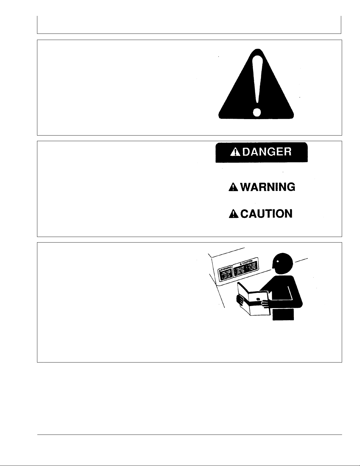
Understand Signal Words
A signal word—DANGER, WARNING, or CAUTION—is
used with the safety-alert symbol. DANGER identies the
most serious hazards.
DANGER or WARNING safety signs are located near
specic hazards. General precautions are listed on
CAUTION safety signs. CAUTION also calls attention to
safety messages in this manual.
T81389 —UN—07DEC88
DX,ALERT -19-29SEP98-1/1
Follow Safety Instructions
Carefully read all safety messages in this manual and on
your machine safety signs. Keep safety signs in good
condition. Replace missing or damaged safety signs. Be
sure new equipment components and repair parts include
the current safety signs. Replacement safety signs are
available from your John Deere dealer.
There can be additional safety information contained on
parts and components sourced from suppliers that is not
reproduced in this operator's manual.
Learn how to operate the machine and how to use controls
properly. Do not let anyone operate without instruction.
Keep your machine in proper working condition.
Unauthorized modications to the machine may impair the
function and/or safety and affect machine life.
TS187 —19—30SEP88
DX,SIGNAL -19-03MAR93-1/1
TS201 —UN—23AUG88
If you do not understand any part of this manual and need
assistance, contact your John Deere dealer.
DX,READ -19-16JUN09-1/1
05-1
101311
PN=5
Page 6
Safety
Practice Safe Maintenance
Understand service procedure before doing work. Keep
area clean and dry.
Never lubricate, service, or adjust machine while it is
moving. Keep hands, feet , and clothing from power-driven
parts. Disengage all power and operate controls to relieve
pressure. Lower equipment to the ground. Stop the
engine. Remove the key. Allow machine to cool.
Securely support any machine elements that must be
raised for service work.
Keep all parts in good condition and properly installed.
Fix damage immediately. Replace worn or broken parts.
Remove any buildup of grease, oil, or debris.
On self-propelled equipment, disconnect battery ground
cable (-) before making adjustments on electrical systems
or welding on machine.
On towed implements, disconnect wiring harnesses from
tractor before servicing electrical system components or
welding on machine.
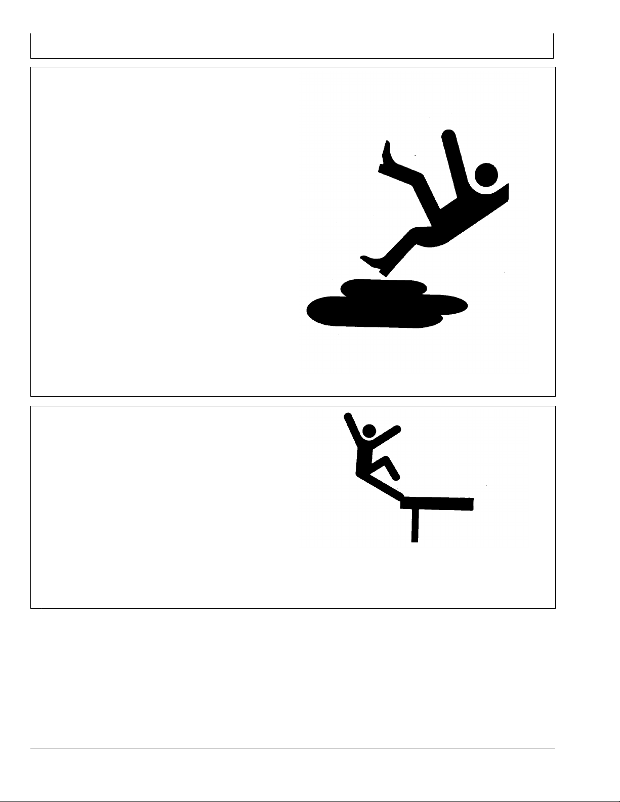
Handle Electronic Components and Brackets Safely
Falling while installing or removing electronic components
mounted on equipment can cause serious injury. Use a
ladder or platform to easily reach each mounting location.
Use sturdy and secure footholds and handholds. Do not
install or remove components in wet or icy conditions.
If installing or servicing a RTK base station on a tower or
other tall structure, use a certied climber.
If installing or servicing a global positioning receiver mast
used on an implement, use proper lifting techniques and
wear proper protective equipment. The mast is heavy and
can be awkward to handle. Two people are required when
mounting locations are not accessible from the ground
or from a service platform.
TS218 —UN—23AUG88
DX,SERV -19-17FEB99-1/1
TS249 —UN—23AUG88
DX,WW,RECEIVER -19-24AUG10-1/1
05-2
101311
PN=6
Page 7
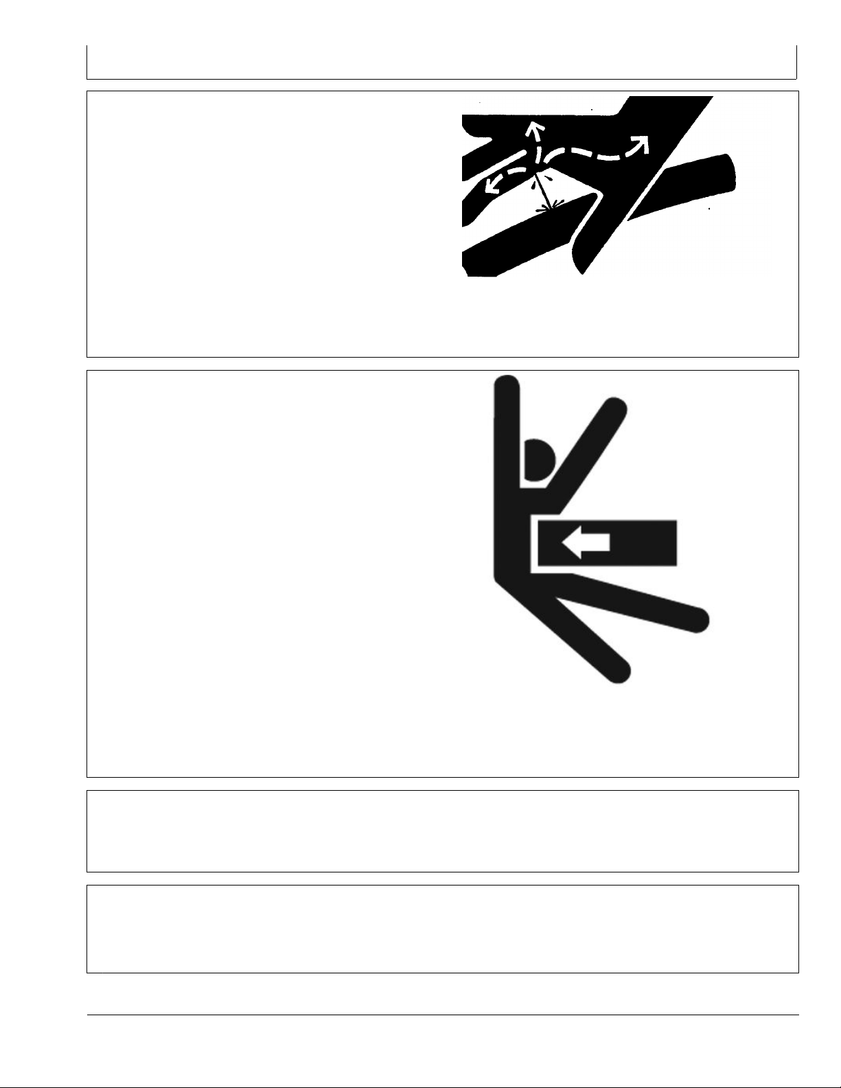
Avoid High-Pressure Fluids
Escaping uid under pressure can penetrate the skin
causing serious injury.
Avoid the hazard by relieving pressure before
disconnecting hydraulic or other lines. Tighten all
connections before applying pressure.
Search for leaks with a piece of cardboard. Protect hands
and body from high-pressure uids.
Safety
If an accident occurs, see a doctor immediately. Any uid
injected into the skin must be surgically removed within
a few hours or gangrene may result. Doctors unfamiliar
with this type of injury should reference a knowledgeable
medical source. Such information is available in
English from Deere & Company Medical Department in
Operate Implement Automation Systems Safely
Do not use implement automation systems on roadways.
Always turn off (disable) implement automation systems
before entering a roadway. Do not attempt to turn
on (activate) an implement automation system while
transporting on a roadway.
Implement automation systems are intended to aid the
operator in performing eld operations more efciently.
The operator is always responsible for the machine path.
Implement automation systems include any application
that automates implement movement. This includes
but may not be limited to iGrade and Active Implement
Guidance.
To prevent injury to the operator and bystanders:
Verify the machine, Implement, and automation systems
•
are set up correctly.
Remain alert and pay attention to the surrounding
•
environment.
Take control of the implement when necessary to
•
avoid eld hazards, bystanders, equipment, or other
obstacles.
Moline, Illinois, U.S.A., by calling 1-800-822-8262 or +1
309-748-5636.
DX,FLUID -19-20AUG09-1/1
Stop operation if poor visibility conditions impair your
•
ability to operate the machine or identify people or
obstacles in the machine path.
CF86321,0000366 -19-25MAY11-1/1
X9811 —UN—23AUG88
PC13793 —UN—25MAY11
Read the Operator's Manual
Before attempting to operate iSteer™ or AutoTrac™,
fully read the Operator's Manual to understand
Maintain a Safety Area Around the Implement
Implement movement and parts in motion can cause
serious injury.
05-3
components and procedures required for safe and
proper operation.
OUCC002,0002BCB -19-29SEP09-1/1
Do not, under any circumstances, operate the implement
with iSteer system when people are in the vicinity.
The transport lock must be engaged.
OUCC002,0002D5F -19-20NOV09-1/1
101311
PN=7
Page 8

Introduction
Theory of Operation
iSteer™ is an active implement guidance system which
keeps the implement on track in case the tractor leaves
its predened track. This is done via a StarFire™ GPS
receiver on the tractor or the implement.
The following criteria are required:
For iSteer™ Plough System
Receiver on tractor. StarFire™ SF1, SF2 or RTK
•
(StarFire™ iTC or StarFire™ 3000)
For iSteer™ Side-Shift/Steerable Drawbar System
Receiver on tractor and implement. RTK signal
•
(StarFire™ iTC or StarFire™ 3000)
iSteer™ Basic Requirements
iSteer™ provides implement steering for vario ploughs,
implements mounted on the three-point hitch and drawbar
steered implements (including offset implements).
For iSteer™ Plough, the plough mounted on the
three-point hitch should have some freedom of lateral
movement.
For iSteer™ Side-Shift, the cylinder must be mounted on
the three-point hitch.
iSteer™ Functional Requirements:
GS3 2630 display mounted in machine.
•
iSteer™ activation.
•
AutoTrac™ activation (AutoTrac™ straight track support
•
with Side-Shift, steerable implement drawbar and
Plough steering).
iSteer™ setup complete (incomplete iSteer™ setup
•
would prevent operator from activating guidance).
The following items need to be included:
Hardware:
Implement harness(es) for receiver (quantity may vary)
•
Implement GPS bracket and receiver
•
Compatible with GreenStar™3 2630 display
•
Software and Settings:
Always use components with the latest software
•
versions (i.e. StarFire™ receiver, control unit).
Receiver setup including offsets and TCM calibration
•
NOTE: For highest accuracy and repeatability
RTK signal is required.
OUCC002,0003504 -19-09SEP11-1/1
Update all components with latest software version
•
available.
iSteer™ control unit installed on implement.
•
Implement mounted steering angle sensor.
•
Hydraulic steering mechanism mounted to implement.
•
For iSteer™ Plough System Only: A John Deere
•
GPS receiver is mounted on the tractor.
For iSteer™ Side-Shift System Only: A John Deere
•
GPS receiver is mounted on the implement and tractor.
IMPORTANT: The GPS receiver should be installed
directly above the cylinder in most cases.
Also, avoid areas of excessive vibration
such as above the PTO.
NOTE: Do not mount implement receiver higher than
4.0 m (13.1 ft.) off the ground.
NOTE: iSteer™ steering mode: Straight Track
guidance mode.
OUCC002,0003505 -19-06SEP11-1/1
10-1
101311
PN=8
Page 9
Introduction
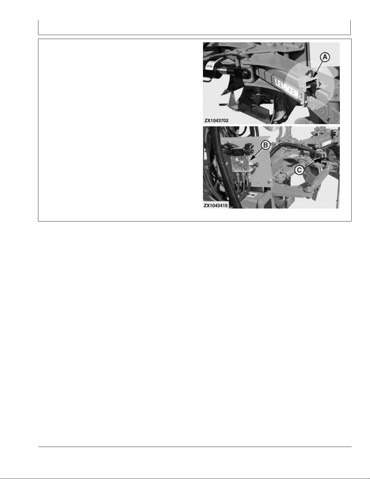
iSteer™ System Basic Operation
iSteer™ Plough System
Basic operation of the iSteer™ Plough system:
1. A steering angle sensor (A) transmits the current
working width to the iSteer™ Plough control unit.
2. The operator calibrates the iSteer™ Plough control
unit with the information regarding the actual working
width by using the buttons on the display.
3. The StarFire™ 3000 receiver is located on the tractor.
The iSteer™ Plough control unit calculates implement
working width using GPS and AB line values set in the
Guidance screen on the GS3 display.
4. When iSteer™ is enabled and activated and when an
offset of the current AB line is detected, a signal is
sent to the plough control valve (B).
5. The control valve (B) directs hydraulic oil to the plough
hydraulic cylinder (C).
6. The entire procedure is repeated from the rst step
to continually monitor any off-track errors. Constant
adjustments of the variable working width are made to
keep the furrow as straight as the dened AB line.
ZX1043702 —UN—30NOV09ZX1043415 —UN—30NOV09
A—Steering Angle Sensor
B—Control Valve
C—Hydraulic Cylinder
Continued on next page OUCC002,0003506 -19-08SEP11-1/2
10-2
101311
PN=9
Page 10
Introduction
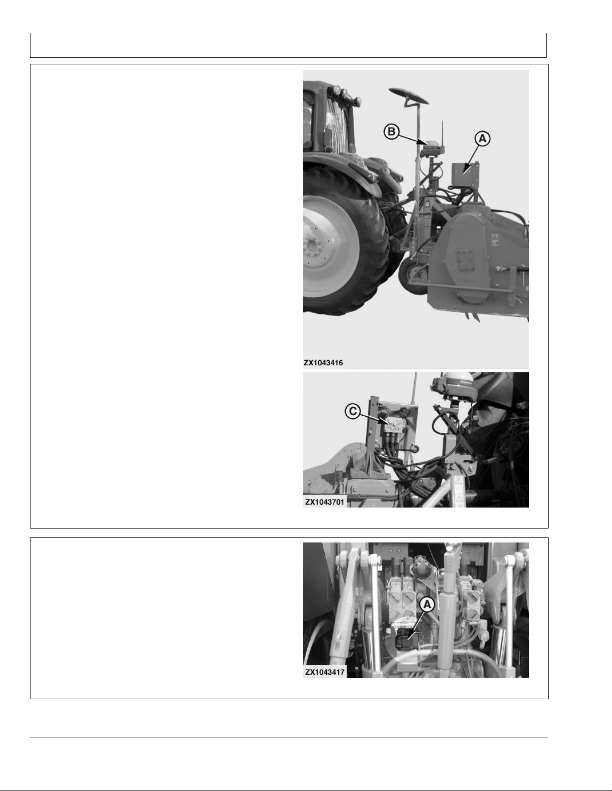
iSteer™ Side-Shift System
Basic operation of the iSteer™ Side-Shift system:
1. A steering angle sensor transmits the location of the
implement to the iSteer™ Side-Shift control unit (A).
2. The operator calibrates the iSteer™ Side-Shift control
unit with this implement information by using the
buttons on the display.
3. The iSteer™ Side-Shift control unit calculates the
implement off-track error using GPS (B) and the AB
line values set in Guidance screen on the GS3 display.
4. When iSteer™ is enabled and activated, and if
implement requires steering adjustment to bring it back
onto AB line, a signal is sent from iSteer™ Side-Shift
control unit to the implement control valve (C).
5. The control valve directs hydraulic oil to the implement
side-shift hydraulic cylinder.
6. The entire procedure is repeated from the rst step
to continually monitor any off-track errors. Constant
adjustments are made to keep the implement steering
towards the currently active AB line.
A—Control Unit
B—GPS Receiver
C—Control Valve
Connect the iSteer™ System
Connect iSteer™ control unit wiring harness to the
ISOBUS connector (A).
Connect all hydraulic hoses to their relevant tractor quick
couplers (see iSteer™ installation instructions).
ZX1043416 —UN—30NOV09ZX1043701 —UN—30NOV09
OUCC002,0003506 -19-08SEP11-2/2
A—ISOBUS Connector
10-3
ZX1043417 —UN—30SEP09
OUCC002,0003507 -19-06SEP11-1/1
101311
PN=10
Page 11
GS3 Display - iSteer™ Plough
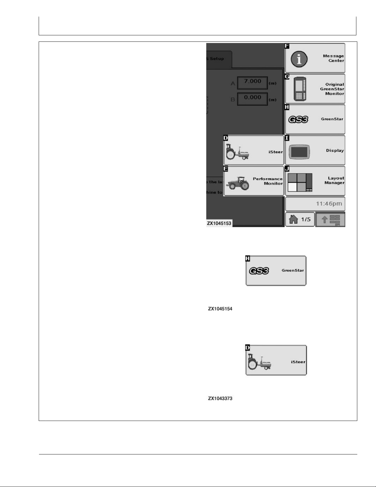
Access iSteer™ Plough
Before accessing iSteer™ Plough, make sure that:
The iSteer™ licence activation is done.
•
NOTE: When iSteer™ control unit is connected, the
Straight Track guidance mode is automatically
preselected. This mode in the GS3 Guidance
settings is then grayed out.
The farm, eld, and client setup is done.
•
The initial path (AB line) has been set.
•
The plough working width has been calculated correctly
•
(sensor calibrated). See Calibrate the Plough Working
Width in this Section.
Press GreenStar 3 Pro button and refer to 2630
GreenStar Display Operator's Manual to proceed .
Press iSteer™ button to operate the iSteer™ Plough
system. The iSteer™ main page appears and displays
three tabs.
Refer to:
iSteer™ Plough - RUN Page,
•
iSteer™ Plough - SETUP Page or
•
iSteer™ Plough - GPS SETUP Page in this Section.
•
GreenStar 3 Pro Button
iSteer™ Button
ZX1045153 —UN—19AUG11ZX1045154 —UN—19AUG11
ZX1043373 —UN—17SEP09
15-1
OUCC002,0003508 -19-06SEP11-1/1
101311
PN=11
Page 12
GS3 Display - iSteer™ Plough
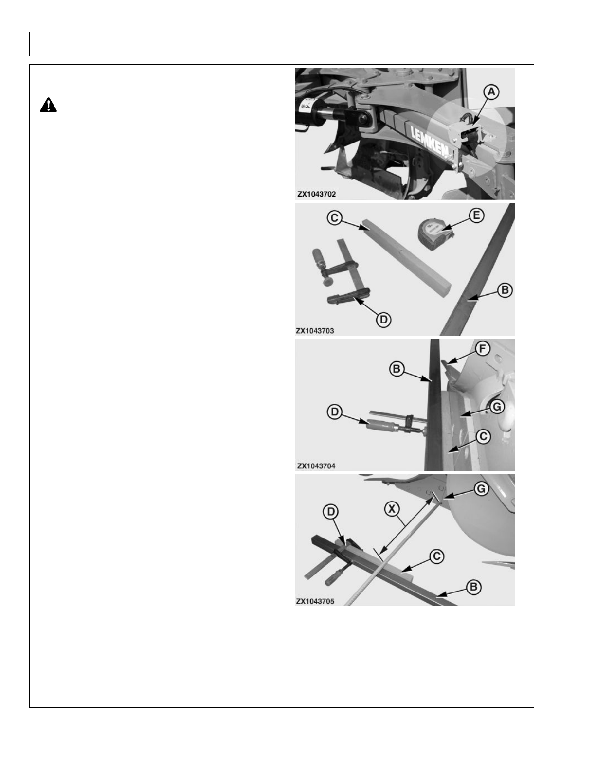
Calibrate the Plough Working Width
CAUTION: Ensure there are no bystanders near
the implement during calibration.
To obtain accurate working width measurement results
from the plough control unit, it is essential to calibrate
the working width sensor (A) after its installation on the
plough frame.
NOTE: Inaccurate measurement causes the ploughing
width to be wider or narrower than calculated by
the control unit. As a result, the tractor always
drives beside its line on the GS3 display.
To calibrate the sensor (A), proceed as follows :
Requirements:
A +/- 3 m (10 ft.) straight iron bar (B).
•
Two equally thick slats (C).
•
Two clamps (D).
•
A measuring tape (E).
•
1. Mounting the bar to the plough:
Put the plough on a at surface. Clamp the bar (B) to
the side cap (G) of the plough element and let the bar
extend to the front.
ZX1043702 —UN—30NOV09ZX1043703 —UN—30NOV09ZX1043704 —UN—30NOV09ZX1043705 —UN—30NOV09
IMPORTANT: The bar (B) must be mounted exactly
parallel to the side cap of the plough element.
Because the edge of the share (F) is wider
than the side cap (G), the bar (B) must be
mounted with a slat (C) in between .
2. Measuring the plough:
Adjust the width of the plough to its narrowest
(contract) position.
3. Measure the distance (X) between the side cap (G)
and the second slat (C) which is clamped to the bar (B).
4. Convert the measured width (X) to the total ploughing
width. To do this, divide the measured width (X) by the
number of measured elements. Multiply the result with
the total number of elements.
Example for a three-element plough: Adjust the
plough to its minimum width.
a. Measure the working width of two elements.
b. To calculate the total ploughing width, the measured
width is divided by 2 and the value obtained is then
multiplied by 3. If the measured width is for instance
58 cm (23 in.), the minimum total ploughing width
is: 58 / 2 x 3 = 87 cm (34 in.).
5. Measure and calculate the maximum ploughing width
in the same way.
IMPORTANT: If the plough has four elements or more,
it is recommended to measure the distance
between at least three elements.
A—Sensor
B—Bar
C—Slat
D—Clamp
Continued on next page OUCC002,0003509 -19-06SEP11-1/2
E—Measuring Tape
F— Share
G—Side Cap
X—Distance to measure
15-2
101311
PN=12
Page 13

GS3 Display - iSteer™ Plough
Check if measured widths (X) (narrow and wide) are equal
to those displayed in the graph on the iSteer™ Plough
- RUN Page on the GS3 display (see iSteer™ Plough -
RUN Page). If they are not equal, the sensor (A) must
be readjusted accordingly.
OUCC002,0003509 -19-06SEP11-2/2
15-3
101311
PN=13
Page 14
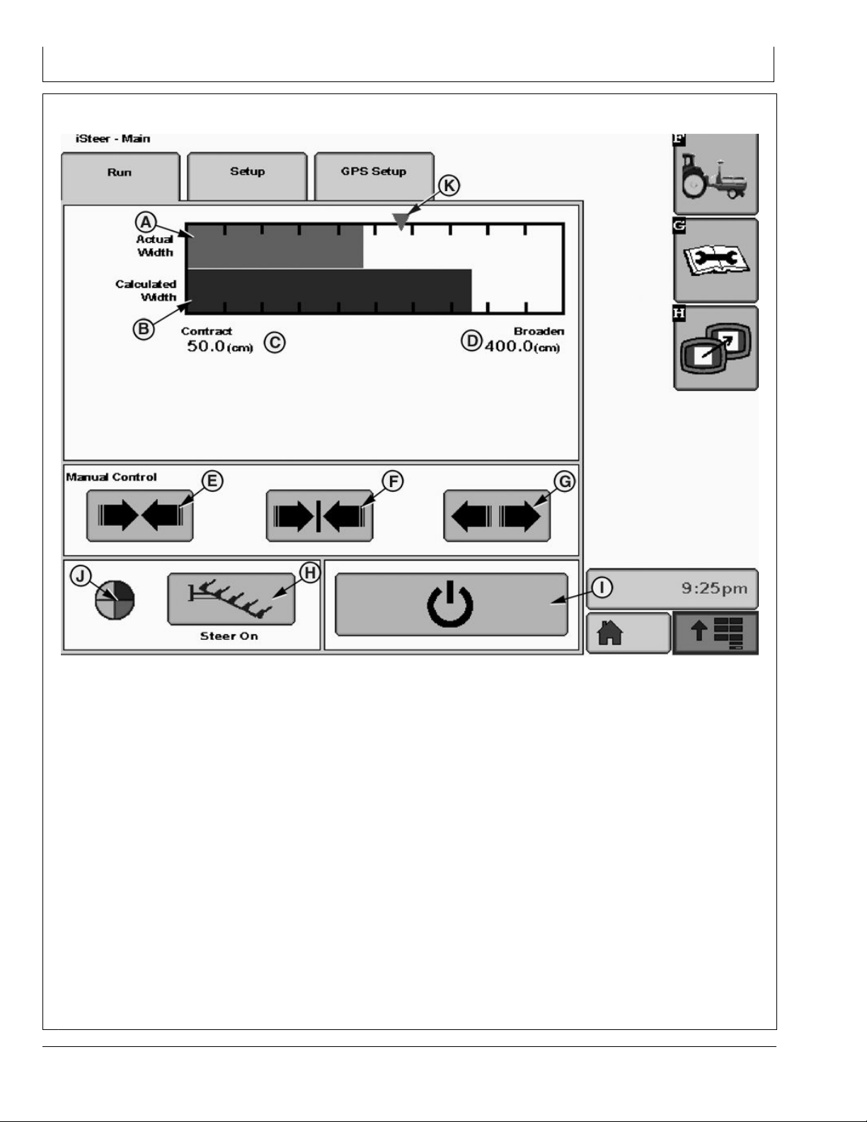
iSteer™ Plough - RUN Page
GS3 Display - iSteer™ Plough
A—Actual Width
B—Calculated Width
C—Contract - element minimum
limit when contracted
D—Broaden - element maximum
limit when broadened
E—Manual Contract Button
F— Manual Set to Working Width
Button
The RUN page allows the operator to:
Visually check the plough width by referencing the bar
•
graph actual width display (A) and calculated width
display (B) between the plough contract position (C),
broaden position (D) and desired working width (K), as
shown.
NOTE: In case of erratic movements of the bar
graph, check sensor.
NOTE: Desired working width cursor (K) position
corresponds to the value entered in the
implement setup on the GS3 display.
Manually control the plough width using Contract button
•
(E), Set to Working Width button (F) or Broaden button
(G).
G—Manual Broaden Button
H—Enable iSteer™ Button
I— Activate iSteer™ Button
Enable the iSteer™ Plough system using Enable button
•
J— iSteer™ Status Pie
K—Desired Working Width
Cursor
(H).
Activate the iSteer™ Plough system when ploughing
•
using Activate button (I).
Visually check iSteer™ Plough status by referencing
•
status pie (J). Press Diagnostic softkey G to display the
diagnostic page. Refer to iSteer™ Plough - Diagnostic
Page in this Section.
Prior to operating the plough with iSteer™ Plough system,
make sure:
1. All required plough settings and sensor calibration
were performed correctly. Refer to iSteer™ Plough SETUP Page in this Section.
2. GPS settings have been checked. Refer to iSteer™
Plough - GPS SETUP Page in this Section.
Continued on next page OUCC002,000350A -19-06SEP11-1/2
15-4
ZX1045155 —UN—19AUG11
101311
PN=14
Page 15

GS3 Display - iSteer™ Plough
3. Press Enable iSteer™ button (H) and set the initial
path. Refer to GS3 Guidance Operator's Manual to
set the initial path.
IMPORTANT: Only straight track mode is allowed.
Create AB line as explained in relevant
guidance Operator's Manual.
4. Press Activate iSteer™ button (I) to start implement
guidance.
IMPORTANT: When iSteer™ is activated all other
GreenStar Pro modules are deactivated.
OUCC002,000350A -19-06SEP11-2/2
15-5
101311
PN=15
Page 16

iSteer™ Plough - SETUP Page
GS3 Display - iSteer™ Plough
A—Element Limits (cm)
B—User Limits (cm)
C—Number of Elements
D—Working Width (cm)
E—Auto-Width Check Box
F— One direction plough
G—On-Land Plough
H—Activation AutoTrac + iSteer
The SETUP page allows the operator to:
Set plough element limits (A) between 20 and 80 cm
•
(7 and 31.5 in.)
Set plough element user limits (B) which can be the
•
same as or within the range of the element limits (A).
Set the number of plough elements (C) between 3 and
•
15 (default value is 3).
NOTE: The values of the plough element limits (A), (B)
and the number of elements (C) must be consistent
with the working width (D) which corresponds to
the track spacing dened on the Guidance screen.
Check Auto-Width box (E) whenever the plough needs
•
to move to working width upon iSteer™ deactivation.
NOTE: A ground speed of at least 0.5 km/h is
necessary for Auto-Width to function.
I— Calibrate Button
J— Manual Control
K—Invert Steering Check Box
L— Plough Direction Button
Check One direction plough box (F) if this kind of plough
•
M—Desired Working Width
Cursor
is used.
Check On-Land Plough box (G) if tractor drives beside
•
the furrow.
Check Activation AutoTrac + iSteer box (H) to activate
•
AutoTrac™ and iSteer™ simultaneously.
NOTE: This box appears only if On-Land Plough
box (G) has been checked.
Calibrate (I) sensor contract and broaden positions
•
each time a new plough is operated. See Sensor
Calibration hereafter.
Manually control (J) the plough position (contract and
•
broaden).
Continued on next page OUCC002,000350B -19-06SEP11-1/5
15-6
ZX1045156 —UN—06SEP11
101311
PN=16
Page 17

GS3 Display - iSteer™ Plough
IMPORTANT: Use manual control (J) to install
the sensor correctly on the plough. During
manual control operation, oversteering
the cylinder to the left or right position
may damage the sensor.
Check whether the illustration of the plough direction
•
(L) corresponds to the real tractor position in the furrow.
If it does not correspond to the actual position, press
Plough Direction button (L) to adjust tractor position.
Plough direction (A) is displayed with the following
message:
- Place the tractor in the furrow. Make sure the last
movement was in the forward direction. Is your
current situation the same as the picture below?
Press the Toggle button (B), if necessary, then press
the Enter button (D) to conrm or press the Cancel
button (C).
Sensor Calibration
CAUTION: Ensure there are no bystanders near
the implement during calibration.
Check Invert Steering box (K) to invert hydraulic valve
•
direction in case of reversed valve connection.
OUCC002,000350B -19-06SEP11-2/5
Calibrate sensor contract and broaden positions as
follows:
A—Plough Direction
B—Toggle Button
C—Cancel Button
D—Enter Button
ZX1043377 —UN—21NOV09
Continued on next page OUCC002,000350B -19-06SEP11-3/5
15-7
101311
PN=17
Page 18

GS3 Display - iSteer™ Plough
Sensor Calibration - Step 1/2
A—Sensor Setup - 1/2
B—Contract Button
C—Contract Position Value (V)
D—Invert Steering Check Box
E—Next Button
F— Sensor Setup - 2/2
1.
Press the Calibrate button on the RUN page.
2. Sensor setup 1/2 (A) is displayed with the following
message:
”Contract the plough to its most narrow position using
the button below. If the plough broadens, press the
invert steering check box. Then press the next button.”
3. Press and hold Contract button (B) until the desired
voltage level (C) is reached. The limit that can be set
by the operator is 0.75 V or 4.25 V depending on the
sensor mounting location.
NOTE: If the plough broadens instead of contracts,
check the Invert Steering box (D).
4. Press Next button (E) to continue sensor position
calibration process.
ZX1043378 —UN—21NOV09
Sensor Calibration - Step 2/2
ZX1043381 —UN—17SEP09
G—Broaden Button
H—Broaden Position Value (V)
I— Accept Button
J— Alarm Message
K—Alarm Message
L— Cancel Button
5. Sensor setup 2/2 (F) is displayed with the following
message:
”Broaden the plough to its widest position using the
button below. Then press the accept button.”
6. Press and hold Broaden button (G) until the desired
voltage level (H) is reached. The limit that can be set
by the operator is 0.75 V or 4.25 V depending on the
sensor mounting location.
NOTE: Alarm messages ”Sensor value too close to
previous setting.” (J) or ”Sensor value outside valid
range. Consider a different mounting position.” (K)
may appear while pressing Contract or Broaden
button (B, G). The difference between the voltage
settings must be at least 1 V. Follow message
instructions then press Accept button (I).
ZX1043379 —UN—21NOV09
ZX1043382 —UN—17SEP09
Continued on next page OUCC002,000350B -19-06SEP11-4/5
15-8
101311
PN=18
Page 19

GS3 Display - iSteer™ Plough
7. Once calibration is nished, press Accept (I) to
validate calibration.
iSteer™ Plough - GPS SETUP Page
OUCC002,000350B -19-06SEP11-5/5
The GPS SETUP page allows the operator to:
A - Input in-line distance from the GPS receiver to the
•
last plough body.
B - Input lateral distance from center-line of machine
•
to GPS receiver.
NOTE: The receiver height has to be entered in
StarFire™ Settings for correct positioning.
Press Toggle button (C) to select the right tractor/GPS
receiver conguration as shown on illustration and then
input distance A and B values.
C—Toggle Button
15-9
ZX1045157 —UN—19AUG11
ZX1043412 —UN—30SEP09
OUCC002,000350C -19-08SEP11-1/1
101311
PN=19
Page 20

iSteer™ Plough - Diagnostic Page
GS3 Display - iSteer™ Plough
A—Status Pie B—Conditions C—State D—Status
The status pie (A) displayed on the RUN page allows the
operator to view the stage iSteer™ is in.
When iSteer™ is enabled and all conditions (B) are
•
met, the status pie (A) is fully green.
When iSteer™ is activated (active steering of the plough
•
Depending on the conditions (B), the state (C) of the
iSteer™ status pie (A) reects the status (D) to help in
diagnosing the system. Refer to the following chart for
conditions and status description:
and ground speed is above 0.5 km/h) iS is displayed.
iSteer™ Status Pie Conditions/Status Description
State Conditions Status
iSteer Activation Yes/No
1/4 of pie
2/4 of pie
Implement Type Plough
GS3 Ready for iSteer Yes/No
Differential Mode Vehicle SF1/SF2/RTK
AutoTrac Not Active
AB Line Dened Yes/No
Track Spacing Valid Yes/No
No iSteer Trouble Codes Yes/No
Valid iSteer Conguration Yes/No
Sensor Calibration Valid Yes/No
Continued on next page OUCC002,000350D -19-08SEP11-1/2
SF1/SF2/RTK
15-10
ZX1045158 —UN—06SEP11
101311
PN=20
Page 21

GS3 Display - iSteer™ Plough
iSteer™ Status Pie Conditions/Status Description
State Conditions Status
3/4 of pie Steer On/Off Button On/Off
Speed Within Range Yes/No
a
Within 20 Degrees of AB Line Yes/No4/4 of pie with iS
a
If ground speed is above 0.5 km/h
Within 40 % Tracking Width Yes/No
OUCC002,000350D -19-08SEP11-2/2
15-11
101311
PN=21
Page 22

GS3 Display - iSteer™ Side-Shift
Access iSteer™ Side-Shift
Before accessing iSteer™ Side-Shift, make sure that:
The iSteer™ licence activation is done.
•
NOTE: When iSteer™ control unit is connected, the
Straight Track guidance mode is automatically
preselected. This mode in the GS3 Guidance
settings is then grayed out.
The farm, eld, and client setup is done.
•
The initial path (AB line) has been set.
•
Press GreenStar 3 Pro button and refer to 2630
GreenStar Display Operator's Manual to proceed .
Press iSteer™ button to operate the iSteer™ Side-Shift
system. The iSteer™ main page appears and displays
three tabs.
Refer to:
iSteer™ Side-Shift - RUN Page,
•
iSteer™ Side-Shift - SETUP Page or
•
iSteer™ Side-Shift - GPS SETUP Page in this Section.
•
GreenStar 3 Pro Button
iSteer™ Button
ZX1045153 —UN—19AUG11ZX1045154 —UN—19AUG11
ZX1043373 —UN—17SEP09
20-1
OUCC002,000350E -19-06SEP11-1/1
101311
PN=22
Page 23

iSteer™ Side-Shift - RUN Page
GS3 Display - iSteer™ Side-Shift
A—Lateral Offset Graph
B—Cylinder Position
C—Manual Left Side-Shift Button
D—Manual Set to Offset Position
Button
The RUN page allows the operator to:
Visually check the lateral offset (A) and cylinder position
•
(B).
NOTE: In case of erratic movements of the bar
graph or cylinder, check sensor.
NOTE: The graph accuracy (arrow distance) default
is set to 10 cm (3.94 in.) and is adjustable
under Guidance Settings tab (see GS3
Guidance Operator's Manual).
Manually control the cylinder position using Left
•
Side-Shift button (C), Set to Offset Position button (D)
or Right Side-Shift button (E).
NOTE: With manual offset to 0 the implement is
centered (no lateral offset).
E—Manual Right Side-Shift
Button
F— Enable iSteer™ Button
Enable the iSteer™ Side-Shift system using Enable
•
G—Activate iSteer™ Button
H—iSteer™ Status Pie
button (F).
Activate the iSteer™ Side-Shift system using Activate
•
button (G).
Visually check iSteer™ Side-Shift status by referencing
•
the status pie (H). Press Diagnostic softkey G to display
the diagnostic page. Refer to iSteer™ Side-Shift Diagnostic Page in this Section.
Prior to operating the implement with the iSteer™
Side-Shift system, make sure:
1. All requested iSteer™ Side-Shift settings and sensor
calibration were performed correctly. Refer to iSteer™
Side-Shift - SETUP Page in this Section.
2. GPS settings have been checked. Refer to iSteer™
Side-Shift - GPS SETUP Page in this Section.
IMPORTANT: Correct receiver height is critical
to proper operation. This value is entered
in the StarFire™ setup page.
Continued on next page OUCC002,000350F -19-06SEP11-1/2
20-2
ZX1045162 —UN—19AUG11
101311
PN=23
Page 24

GS3 Display - iSteer™ Side-Shift
3. Press Enable iSteer™ button (F) and set the initial
path. Refer to GS3 Guidance Operator's Manual to
set the initial path.
IMPORTANT: Only straight track mode is allowed.
Create AB line as explained in relevant
guidance Operator's Manual.
iSteer™ Side-Shift - SETUP Page
4. Press Activate iSteer™ button (G) to start implement
guidance.
IMPORTANT: When iSteer™ is activated all other
GreenStar Pro modules are deactivated.
OUCC002,000350F -19-06SEP11-2/2
A—Steer Sensitivity
B—Pulse Length (s)
C—Auto-Center Check Box
D—Activation AutoTrac+iSteer
The SETUP page allows the operator to:
Set cylinder steering sensitivity (A) between 50 and 150
•
(default value is 100).
Set cylinder pulse length (B) between 0.1 and 2
•
seconds (default value is 0.3 s).
Check Auto-Center box (C) whenever the implement
•
needs to be moved to the offset position upon iSteer™
deactivation.
E—Calibrate Button
F— Manual Control
Check Activation AutoTrac+iSteer box (D) to activate
•
G—Invert Steering Check Box
AutoTrac and iSteer™ simultaneously.
Calibrate (E) cylinder sensor left and right positions
•
each time a new implement is operated. See Sensor
Calibration hereafter.
Manually control (F) implement position (to the left or
•
right).
Check Invert Steering box (G) to invert hydraulic valve
•
direction in case of reversed valve connection.
Continued on next page OUCC002,0003510 -19-06SEP11-1/3
20-3
ZX1045161 —UN—06SEP11
101311
PN=24
Page 25

Sensor Calibration
GS3 Display - iSteer™ Side-Shift
Sensor Calibration - Step 1/3
CAUTION: Ensure there are no bystanders near
the implement during calibration.
Calibrate sensor left and right positions as follows:
1. Press the Calibrate button on the RUN page.
2. Sensor setup 1/3 (A) is displayed with the following
message:
”Move the side shift cylinder to left position using the
button below. If the cylinder moves to the right, press
the invert steering check box. Press next to continue.”
3. Press and hold Left button (B) until the desired voltage
level (C) is reached. The limit that can be set by the
operator is 0.75 V or 4.25 V.
NOTE: If the cylinder moves to the right instead of to
the left, check the Invert Steering box (D).
4. Press Next button (E) to continue sensor position
calibration process.
5. Sensor setup 2/3 (F) is displayed with the following
message:
”Move the side shift cylinder to right position using the
button below. Press next to continue.”
6. Press and hold Right button (G) until the desired
voltage level (H) is reached. The limit that can be set
by the operator is 0.75 V or 4.25 V.
ZX1043386 —UN—30SEP09
Sensor Calibration - Step 2/3
Sensor Calibration - Step 3/3
A—Sensor Setup - 1/3
B—Left Button
C—Left Position Value (V)
D—Invert Steering Check Box
E—Next Button
F— Sensor Setup - 2/3
ZX1043387 —UN—30SEP09
ZX1043388 —UN—30SEP09
G—Right Button
H—Right Position Value (V)
I— Sensor Setup - 3/3
J— Center Button
K—Accept Button
L— Cancel Button
7. Press Next button (E) to continue sensor position
calibration process.
8. Sensor setup 3/3 (I) is displayed with the following
message:
”Dene Cylinder Offset Position.”
9. Press Left, Center or Right button (B, J or G) to
dene cylinder offset position using cylinder position
illustration, as shown.
Continued on next page OUCC002,0003510 -19-06SEP11-2/3
20-4
101311
PN=25
Page 26

GS3 Display - iSteer™ Side-Shift
10. Once calibration is nished press Accept (K) to
validate calibration.
iSteer™ Side-Shift - GPS SETUP Page
OUCC002,0003510 -19-06SEP11-3/3
The GPS SETUP page allows the operator to:
Input in-line distance from the connection point to GPS
•
receiver (A).
Input lateral distance from the connection point to GPS
•
receiver (B).
Press Toggle button (C) to select the right tractor/GPS
receiver conguration as shown on illustration and then
input distance A and B values.
C—Toggle Button
20-5
ZX1045160 —UN—19AUG11
ZX1043413 —UN—30SEP09
OUCC002,0003511 -19-06SEP11-1/1
101311
PN=26
Page 27

GS3 Display - iSteer™ Side-Shift
iSteer™ Side-Shift - Diagnostic Page
A—Status Pie B—Conditions C—State D—Status
The status pie (A) displayed on the RUN page allows the
operator to view the stage iSteer™ is in.
When iSteer™ is enabled and all conditions (B) are
•
met, the status pie (A) is fully green.
When iSteer™ is activated (active steering of the plough
•
Depending on the conditions (B), the state (C) of the
iSteer™ status pie (A) reects the status (D) to help in
diagnosing the system. Refer to the following chart for
conditions and status description:
and ground speed is above 0.5 km/h) iS is displayed.
iSteer™ Status Pie Conditions/Status Description
State Conditions Status
iSteer Activation Yes/No
1/4 of pie
2/4 of pie
Implement Type
GS3 Ready for iSteer Yes/No
Differential Mode Vehicle
Differential Mode Implement
AB Line Dened Yes/No
Track Spacing Valid Yes/No
No iSteer Trouble Codes Yes/No
Valid iSteer Conguration Yes/No
Sensor Calibration Valid Yes/No
Continued on next page OUCC002,0003512 -19-06SEP11-1/2
Side-Shift
RTK
RTK
20-6
ZX1045159 —UN—06SEP11
101311
PN=27
Page 28

GS3 Display - iSteer™ Side-Shift
iSteer™ Status Pie Conditions/Status Description
State Conditions Status
3/4 of pie Steer On/Off Button On/Off
Speed Within Range Yes/No
a
Within 20 Degrees of AB Line Yes/No4/4 of pie with iS
a
If ground speed is above 0.5 km/h
Within 40 % Tracking Width Yes/No
OUCC002,0003512 -19-06SEP11-2/2
20-7
101311
PN=28
Page 29

GS3 Display - iSteer™ Steerable Drawbar
Operate iSteer™ Steerable Drawbar System
Refer to information given in GS3 Display - iSteer™
Side-Shift Section to access and operate the iSteer™
Steerable Drawbar system.
OUCC002,0003513 -19-06SEP11-1/1
25-1
101311
PN=29
Page 30

Sensor Calibration
GS3 Display - iSteer™ Steerable Drawbar
Sensor Calibration - Step 1/3
CAUTION: Ensure there are no bystanders near
the implement during calibration.
Calibrate sensor left and right positions as follows:
1. Press the Calibrate button on the RUN page.
2. Sensor setup 1/3 (A) is displayed with the following
message:
”Move the side shift cylinder to left position using the
button below. If the cylinder moves to the right, press
the invert steering check box. Press next to continue.”
3. Press and hold Left button (B) until the desired voltage
level (C) is reached. The limit that can be set by the
operator is 0.75 V or 4.25 V.
NOTE: If the cylinder moves to the right instead of to
the left, check the Invert Steering box (D).
4. Press Next button (E) to continue sensor position
calibration process.
5. Sensor setup 2/3 (F) is displayed with the following
message:
”Move the side shift cylinder to right position using the
button below. Press next to continue.”
6. Press and hold Right button (G) until the desired
voltage level (H) is reached. The limit that can be set
by the operator is 0.75 V or 4.25 V.
ZX1043386 —UN—30SEP09
Sensor Calibration - Step 2/3
Sensor Calibration - Step 3/3
A—Sensor Setup - 1/3
B—Left Button
C—Left Position Value (V)
D—Invert Steering Check Box
E—Next Button
F— Sensor Setup - 2/3
ZX1043387 —UN—30SEP09
ZX1043418 —UN—30SEP09
G—Right Button
H—Right Position Value (V)
I— Sensor Setup - 3/3
J— Center Button
K—Accept Button
L— Cancel Button
7. Press Next button (E) to continue sensor position
calibration process.
8. Sensor setup 3/3 (I) is displayed with the following
message:
”Dene Cylinder Offset Position.”
9. Press Left, Center or Right button (B, J or G) to
dene cylinder offset position using cylinder position
illustration, as shown.
Continued on next page OUCC002,0003514 -19-06SEP11-1/2
25-2
101311
PN=30
Page 31

GS3 Display - iSteer™ Steerable Drawbar
NOTE: For applications requiring no offset, make sure
cylinder is centered by pressing the Center button (J).
10. Once calibration is nished press Accept (K) to
validate calibration.
OUCC002,0003514 -19-06SEP11-2/2
25-3
101311
PN=31
Page 32

Service
iSteer™ System Service
General: Due to the use of an electronic control unit,
there is minimal service required to maintain performance
levels. However, periodic software updates may be
required. To maintain optimum performance, these
updates should be loaded.
GS3 Display: For the GS3 system, updating is
accomplished when you perform a ”live update”
Implement Service
Contact the manufacturer of the implement steering
module for servicing procedures.
using a connection to the Stellar Support website
(www.stellarsupport.com). Once downloaded, the updates
must be loaded onto your USB device. After updating
the USB device, the operating system will prompt you
that updates are available the next time you insert the
card into your GS3.
Implement Control Unit: Contact your control unit
manufacturer to keep control unit software up to date.
OUCC002,00034A2 -19-06SEP11-1/1
OUCC002,0002BCC -19-17AUG09-1/1
30-1
101311
PN=32
Page 33

Specications
4.84.8 8.8 9.8 10.9
12.9
12.9
12.9
12.9
10.9
9.8
8.8
4.8
Metric Bolt and Screw Torque Values
TS1670 —UN—01MAY03
Bolt or Screw
Size Lubricated
Class 4.8 Class 8.8 or 9.8 Class 10.9 Class 12.9
a
Dry
b
Lubricated
a
Dry
b
Lubricated
a
Dry
b
Lubricated
a
N·m lb.-in. N·m lb.-in. N·m lb.-in. N·m lb.-in. N·m lb.-in. N·m lb.-in. N·m lb.-in. N·m lb.-in.
M6 4.7 42 6 53 8.9 79 11.3 100 13 115 16.5 146 15.5 137 19.5 172
N·m lb.-ft. N·m lb.-ft. N·m lb.-ft. N·m lb.-ft.
M8 11.5 102 14.5 128 22 194 27.5 243 32 23.5 40 29.5 37 27.5 47 35
N·m lb.-ft. N·m lb.-ft. N·m lb.-ft.
M10 23 204 29 21 43 32
N·m
lb.-ft.
M12 40 29.5 50 37
75 55
55
40 63 46 80 59
95 70 110 80 140 105 130 95 165 120
75 55
M14 63 46 80 59 120 88 150 110 175 130 220 165 205 150 260 190
M16 100 74 125 92 190 140 240 175 275 200 350 255 320 235 400 300
M18 135 100 170 125 265 195 330 245 375 275 475 350 440 325 560 410
M20 190 140 245 180 375 275 475 350 530 390 675 500 625 460 790 580
M22 265 195 330 245 510 375 650 480 725 535 920 680 850 625 1080 800
M24 330 245 425 315 650 480 820 600 920 680 1150 850 1080 800 1350 1000
M27 490 360 625 460 950 700 1200 885 1350 1000 1700 1250 1580 1160 2000 1475
M30 660 490 850 625 1290 950 1630 1200 1850 1350 2300 1700 2140 1580 2700 2000
M33 900 665 1150 850 1750 1300 2200 1625 2500 1850 3150 2325 2900 2150 3700 2730
M36 1150 850 1450 1075 2250 1650 2850 2100 3200 2350 4050 3000 3750 2770 4750 3500
Torque values listed are for general use only, based on the strength of
the bolt or screw. DO NOT use these values if a different torque value or
tightening procedure is given for a specic application. For stainless steel
fasteners or for nuts on U-bolts, see the tightening instructions for the
specic application. Tighten plastic insert or crimped steel type lock nuts
by turning the nut to the dry torque shown in the chart, unless different
instructions are given for the specic application.
Shear bolts are designed to fail under predetermined loads. Always
replace shear bolts with identical property class. Replace fasteners with
the same or higher property class. If higher property class fasteners are
used, tighten these to the strength of the original. Make sure fastener
threads are clean and that you properly start thread engagement. When
possible, lubricate plain or zinc plated fasteners other than lock nuts,
wheel bolts or wheel nuts, unless different instructions are given for the
specic application.
a
“Lubricated” means coated with a lubricant such as engine oil, fasteners with phosphate and oil coatings, or M20
and larger fasteners with JDM F13C, F13F or F13J zinc ake coating.
b
“Dry” means plain or zinc plated without any lubrication, or M6 to M18 fasteners with JDM F13B, F13E or F13H zinc ake coating.
DX,TORQ2 -19-12JAN11-1/1
b
Dry
95 70
35-1
101311
PN=33
Page 34

Specications
EC Declaration of Conformity
Deere & Company
Moline, Illinois U.S.A
The person named below declares that
The iSteer™ System
Model: Plough, Side-Shift and Steerable Drawbar
fullls all relevant provisions and essential requirements of the following directives:
DIRECTIVE
Electromagnetic Compatibility 2004/108/EC Self certied, per Annex II of the Directive
Name and address of the person in the European Community authorized to compile the technical construction le:
Brigitte Birk
Deere & Company European Ofce
John Deere Strasse 70
Mannheim, Germany D-68163
EUConformity@JohnDeere.com
Place of declaration: D-66482 Zweibrücken,
Germany
Date of declaration: 01 August 2009 Title: Engineering Manager AMS Europe
Manufacturing unit: John Deere AMS Europe
NUMBER
CERTIFICATION METHOD
Name: John H. Leinart
DXCE01 —UN—28APR09
OUCC002,0003515 -19-06SEP11-1/1
35-2
101311
PN=34
Page 35

Index
B
Bolt and screw torque values
Metric ...................................................................... 35-1
C
Calibrating
Plough Working Width ............................................ 15-2
H
Hardware torque values
Metric ...................................................................... 35-1
I
iSteer Plough
Accessing................................................................ 15-1
Calibrating............................................................... 15-2
Diagnostic Page.................................................... 15-10
GPS SETUP Page.................................................. 15-9
Operating ....................................................... 15-2, 15-9
iSteer™ Plough
Operating ................................................................ 15-4
RUN Page............................................................... 15-4
Setting..................................................................... 15-6
SETUP Page........................................................... 15-6
iSteer Side-Shift
Setting..................................................................... 20-3
SETUP Page........................................................... 20-3
iSteer™ Side-Shift
Accessing................................................................ 20-1
Diagnostic Page...................................................... 20-6
GPS SETUP Page.................................................. 20-5
Operating ....................................................... 20-2, 20-5
RUN Page............................................................... 20-2
iSteer Steerable Drawbar
Operating ................................................................ 25-1
Setting..................................................................... 20-3
SETUP Page........................................................... 20-3
iSteer™ Steerable Drawbar
Accessing................................................................ 20-1
Diagnostic Page...................................................... 20-6
GPS SETUP Page.................................................. 20-5
Operating ....................................................... 20-2, 20-5
RUN Page............................................................... 20-2
Page
Page
T
Torque charts
Metric ...................................................................... 35-1
M
Metric bolt and screw torque values ........................... 35-1
S
Service........................................................................ 30-1
Index-1
101311
PN=1
Page 36

Index
Index-2
101311
PN=2
Page 37

John Deere Service Keeps You On The Job
John Deere Parts
We help minimize downtime by putting genuine John
Deere parts in your hands in a hurry.
That’s why we maintain a large and varied inventory—to
stay a jump ahead of your needs.
The Right Tools
Precision tools and testing equipment enable our Service
Department to locate and correct troubles quickly . . . to
save you time and money.
TS100 —UN—23AUG88
DX,IBC,A -19-04JUN90-1/1
Well-Trained Technicians
School is never out for John Deere service technicians.
Training schools are held regularly to be sure our
personnel know your equipment and how to maintain it.
Result?
Experience you can count on!
Prompt Service
Our goal is to provide prompt, efcient care when you
want it and where you want it.
We can make repairs at your place or at ours, depending
on the circumstances: see us, depend on us.
JOHN DEERE SERVICE SUPERIORITY: We'll be around
when you need us.
TS101 —UN—23AUG88
DX,IBC,B -19-04JUN90-1/1
TS102 —UN—23AUG88
DX,IBC,C -19-04JUN90-1/1
IBC-1
TS103 —UN—23AUG88
DX,IBC,D -19-04JUN90-1/1
101311
PN=37
Page 38

John Deere Service Keeps You On The Job
IBC-2
101311
PN=38
Page 39

John Deere Service Keeps You On The Job
IBC-3
101311
PN=39
Page 40

John Deere Service Keeps You On The Job
IBC-4
101311
PN=40
Page 41

John Deere Service Keeps You On The Job
IBC-5
101311
PN=41
Page 42

Page 43

Page 44

 Loading...