

Page 1
iGrade™
*DCY*
*OMPFP13592*
OPERATOR'S MANUAL
OMPFP13592 ISSUE C4 (ENGLISH)
*OMPFP13592*
Proposition 65 Warning
iGrade™
CALIFORNIA
Diesel engine exhaust and some of its constituents
are known to the State of California to cause cancer,
birth defects, and other reproductive harm.
If this product contains a gasoline engine:
WARNING
The engine exhaust from this product contains
chemicals known to the State of California to cause
cancer, birth defects or other reproductive harm.
The State of California requires the above two warnings.
Additional Proposition 65 Warnings can be found in this manual.
John Deere Ag Management Solutions
PRINTED IN U.S.A.
Page 2

Introduction
www.StellarSupport.com
NOTE: Product functionality may not be fully represented in this document due to product changes occurring after the time of printing. Read the
latest Operator's Manual and Quick Reference Guide prior to operation. To obtain a copy, see your dealer or visit www.StellarSupport.com
OUO6050,0000FB1 -19-10AUG10-1/1
Foreword
WELCOME to the iGrade™ System offered by John
Deere.
READ THIS MANUAL carefully to learn how to operate and
service your system correctly. Failure to do so could result
in personal injury or equipment damage. This manual and
safety signs on your machine may also be available in
other languages. (See your John Deere dealer to order.)
THIS MANUAL SHOULD BE CONSIDERED a permanent
part of your system and should remain with the system
when you sell it.
MEASUREMENTS in this manual are given in both
metric and customary U.S. unit equivalents. Use only
correct replacement parts and fasteners. Metric and inch
fasteners may require a specific metric or inch wrench.
RIGHT-HAND AND LEFT-HAND sides are determined by
facing in the direction of forward travel.
WRITE PRODUCT IDENTIFICATION NUMBERS (P.I.N.)
in the Specification or Identification Numbers section.
iGrade is a trademark of Deere & Company
Accurately record all the numbers to help in tracing
the components should it be stolen. Your dealer also
needs these numbers when you order parts. File the
identification numbers in a secure place off the machine.
WARRANTY is provided as part of John Deere's support
program for customers who operate and maintain their
equipment as described in this manual. The warranty is
explained on the warranty certificate which you should
have received from your dealer.
This warranty provides you the assurance that John
Deere will back its products where defects appear within
the warranty period. In some circumstances, John Deere
also provides field improvements, often without charge
to the customer, even if the product is out of warranty.
Should the equipment be abused, or modified to change
its performance beyond the original factory specifications,
the warranty will become void and field improvements
may be denied.
RW00482,0000266 -19-19FEB14-1/1
031214
PN=2
Page 3

Contents
Page
Safety
Recognize Safety Information ............................05-1
Understand Signal Words...................................05-1
Follow Safety Instructions...................................05-1
Practice Safe Maintenance.................................05-2
Use Steps and Handholds Correctly ..................05-2
Handle Electronic Components and
Brackets Safely ..............................................05-3
Operate Implement Automation
Systems Safely ..............................................05-3
Avoid High-Pressure Fluids ................................05-4
Introduction
Theory of Operation............................................10-1
Activate iGrade™ ............................................... 10-1
iGrade™ Requirements......................................10-2
Machine Controller Compatibility........................10-3
Page
Operation............................................................ 35-3
Grade Control
Theory of Operation............................................40-1
Grade Calculator ................................................ 40-1
Selecting Grade..................................................40-2
Plane Control
Theory of Operation............................................45-1
Control Selection ................................................45-2
Select Active Plane.............................................45-2
Single Slope Plane .............................................45-3
Dual Slope Plane................................................45-4
Plane Calculator .................................................45-5
Dual Scraper.......................................................45-5
Operation............................................................ 45-6
System Components
iGrade™ Components........................................15-1
SCV Setup
Configure SCVs On CommandCen-
ter™ - Auto Mode........................................... 20-1
SCV Operation ................................................... 20-2
Adjust Valve........................................................20-3
Calibrate SCV Thresholds ..................................20-3
Basic Operation
Basic Operation ..................................................25-1
Engage iGrade™................................................25-2
Dual Scrapers.....................................................25-3
Load Limiting ......................................................25-4
Max Cut ..............................................................25-5
Offsets ................................................................25-6
Remote Control—Surface Water Pro™ Plus
Theory of Operation............................................30-1
Control Selection ................................................30-1
Operation............................................................ 30-2
Remote Control—Serial Port
Theory of Operation............................................35-1
Message Definition .............................................35-1
Serial Port Hardware ..........................................35-1
Serial Port Setup ................................................35-2
Control Selection ................................................35-3
Distance Trip
Theory of Operation............................................50-1
Select Distance Trip ...........................................50-1
Distance Trip Setup ............................................50-2
Initiating Trip Cycle .............................................50-3
Adjusting Trip Cycle............................................50-3
Disconnecting iGrade™
Disconnect iGrade™ System .............................55-1
Troubleshooting
Troubleshooting — iGrade™ System.................60-1
Troubleshooting — I/O Voltages Page ...............60-2
Troubleshooting — Machine...............................60-3
Maintenance
iGrade System....................................................65-1
Preseason Checklist...........................................65-1
Daily Checklist ....................................................65-1
Postseason Checklist .........................................65-2
Specifications
EC Declaration of Conformity.............................70-1
Original Instructions. All information, illustrations and specifications in this
manual are based on the latest information available at the time of publication.
The right is reserved to make changes at any time without notice.
COPYRIGHT © 2014
DEERE & COMPANY
Moline, Illinois
A John Deere ILLUSTRUCTION ® Manual
All rights reserved.
i
031214
PN=1
Page 4

Contents
ii
031214
PN=2
Page 5
Safety
Recognize Safety Information
This is a safety-alert symbol. When you see this symbol
on your machine or in this manual, be alert to the potential
for personal injury.
Follow recommended precautions and safe operating
practices.
Understand Signal Words
A signal word—DANGER, WARNING, or CAUTION—is
used with the safety-alert symbol. DANGER identifies the
most serious hazards.
DANGER or WARNING safety signs are located near
specific hazards. General precautions are listed on
CAUTION safety signs. CAUTION also calls attention to
safety messages in this manual.
T81389 —UN—28JUN13
DX,ALERT -19-29SEP98-1/1
Follow Safety Instructions
Carefully read all safety messages in this manual and on
your machine safety signs. Keep safety signs in good
condition. Replace missing or damaged safety signs. Be
sure new equipment components and repair parts include
the current safety signs. Replacement safety signs are
available from your John Deere dealer.
There can be additional safety information contained on
parts and components sourced from suppliers that is not
reproduced in this operator's manual.
Learn how to operate the machine and how to use controls
properly. Do not let anyone operate without instruction.
Keep your machine in proper working condition.
Unauthorized modifications to the machine may impair the
function and/or safety and affect machine life.
TS187 —19—30SEP88
DX,SIGNAL -19-03MAR93-1/1
TS201 —UN—15APR13
If you do not understand any part of this manual and need
assistance, contact your John Deere dealer.
DX,READ -19-16JUN09-1/1
05-1
031214
PN=5
Page 6
Practice Safe Maintenance
Understand service procedure before doing work. Keep
area clean and dry.
Never lubricate, service, or adjust machine while it is
moving. Keep hands, feet , and clothing from power-driven
parts. Disengage all power and operate controls to relieve
pressure. Lower equipment to the ground. Stop the
engine. Remove the key. Allow machine to cool.
Securely support any machine elements that must be
raised for service work.
Keep all parts in good condition and properly installed.
Fix damage immediately. Replace worn or broken parts.
Remove any buildup of grease, oil, or debris.
On self-propelled equipment, disconnect battery ground
cable (-) before making adjustments on electrical systems
or welding on machine.
On towed implements, disconnect wiring harnesses from
tractor before servicing electrical system components or
welding on machine.
Safety
Use Steps and Handholds Correctly
Prevent falls by facing the machine when getting on and
off. Maintain 3-point contact with steps, handholds, and
handrails.
Use extra care when mud, snow, or moisture present
slippery conditions. Keep steps clean and free of grease
or oil. Never jump when exiting machine. Never mount or
dismount a moving machine.
TS218 —UN—23AUG88
DX,SERV -19-17FEB99-1/1
T133468 —UN—15APR13
DX,WW,MOUNT -19-12OCT11-1/1
05-2
031214
PN=6
Page 7
Handle Electronic Components and Brackets
Safely
Falling while installing or removing electronic components
mounted on equipment can cause serious injury. Use a
ladder or platform to easily reach each mounting location.
Use sturdy and secure footholds and handholds. Do not
install or remove components in wet or icy conditions.
If installing or servicing a RTK base station on a tower or
other tall structure, use a certified climber.
Safety
If installing or servicing a global positioning receiver mast
used on an implement, use proper lifting techniques and
wear proper protective equipment. The mast is heavy and
can be awkward to handle. Two people are required when
mounting locations are not accessible from the ground
or from a service platform.
Operate Implement Automation Systems Safely
Do not use implement automation systems on roadways.
Always turn off (disable) implement automation systems
before entering a roadway. Do not attempt to turn
on (activate) an implement automation system while
transporting on a roadway.
Implement automation systems are intended to aid the
operator in performing field operations more efficiently.
The operator is always responsible for the machine path.
Implement automation systems include any application
that automates implement movement. This includes, but
may not be limited to, iGrade™ and Active Implement
Guidance.
To prevent injury to the operator and bystanders:
Verify the machine, implement, and automation systems
•
are set up correctly.
Remain alert and pay attention to the surrounding
•
environment.
Take control of the machine, when necessary, to
•
avoid field hazards, bystanders, equipment, or other
obstacles.
Stop operation if poor visibility conditions impair your
•
ability to operate the machine or identify people or
obstacles in the machine path.
iGrade is a trademark of Deere & Company
TS249 —UN—23AUG88
DX,WW,RECEIVER -19-24AUG10-1/1
PC13793 —UN—25MAY11
CF86321,0000366 -19-19DEC13-1/1
05-3
031214
PN=7
Page 8
Avoid High-Pressure Fluids
Inspect hydraulic hoses periodically – at least once
per year – for leakage, kinking, cuts, cracks, abrasion,
blisters, corrosion, exposed wire braid or any other signs
of wear or damage.
Replace worn or damaged hose assemblies immediately
with John Deere approved replacement parts.
Escaping fluid under pressure can penetrate the skin
causing serious injury.
Avoid the hazard by relieving pressure before
disconnecting hydraulic or other lines. Tighten all
connections before applying pressure.
Search for leaks with a piece of cardboard. Protect hands
and body from high-pressure fluids.
If an accident occurs, see a doctor immediately. Any fluid
injected into the skin must be surgically removed within
a few hours or gangrene may result. Doctors unfamiliar
Safety
X9811 —UN—23AUG88
with this type of injury should reference a knowledgeable
medical source. Such information is available in
English from Deere & Company Medical Department in
Moline, Illinois, U.S.A., by calling 1-800-822-8262 or +1
309-748-5636.
DX,FLUID -19-12OCT11-1/1
05-4
031214
PN=8
Page 9
Theory of Operation
Introduction
iGrade™ is an active elevation control system which uses
selective control valves (SCVs) to control implement
height based off GPS elevation data.
iGrade™ has four functional modes:
Plane Control – used to create a surface design with
•
either a single slope direction or a dual slope direction.
Grade Control – performs desired slope entered based
•
on actual distance traveled not linear distance. Grade
control is not direction-dependent.
Remote Control – receives elevation data commands
•
from an outside source to control implement height
through SCVs to a desired plane or ditch design.
Distance Trip – allows GPS position to trigger machine
•
hydraulics based on distance traveled. For example,
iGrade is a trademark of Deere & Company
StarFire is a trademark of Deere & Company
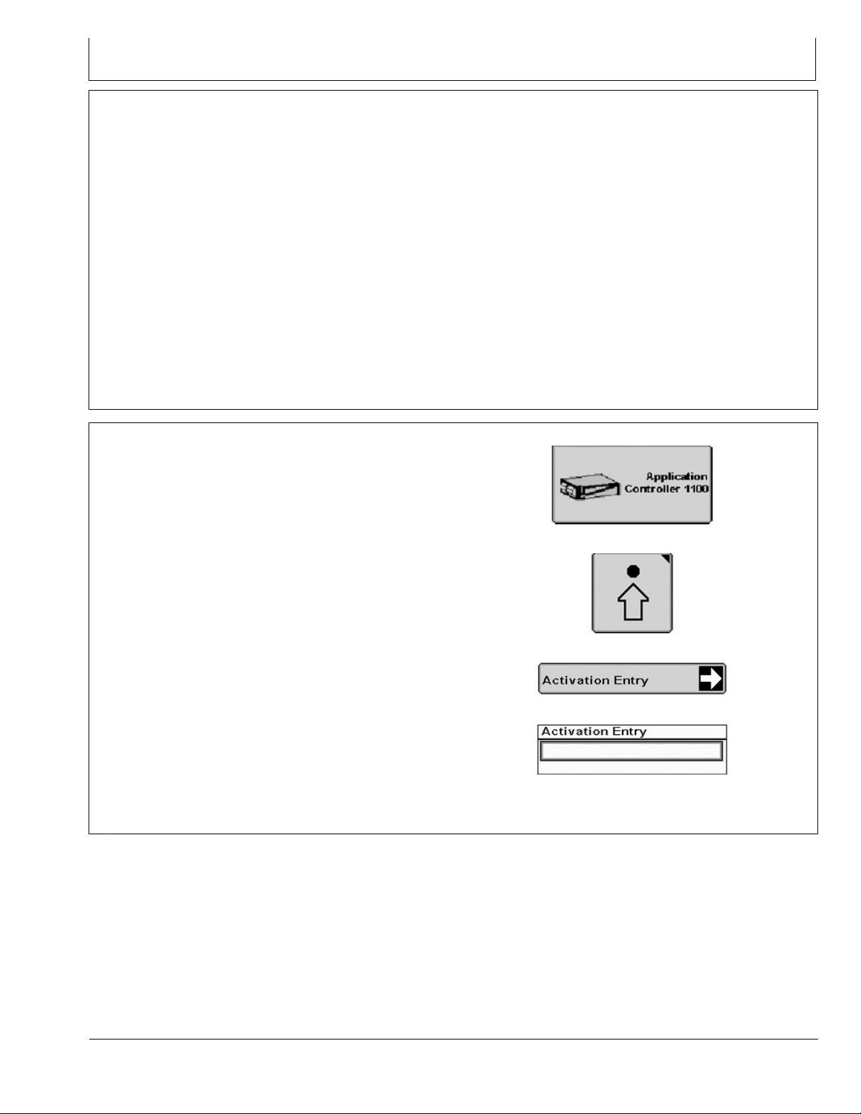
Activate iGrade™
To operate iGrade™, a 26-digit activation code is required
for Application Controller 1100.
1. Visit StellarSupport.com or call 1-888-953-3373.
2. Use controller serial number and COMAR order
number to generate an activation code.
using distance trip to create irrigation bays for bedded
crop irrigation.
iGrade™ utilizes StarFire™ Receivers to obtain a
plane or elevation point correlated to a latitude and
longitude position. To function properly, setup is crucial to
performance. Setup including but is not limited to:
SCV thresholds setup
•
SCV flow rates setup
•
TCM calibrations setup
•
Correctly setting a benchmark daily or a zero point for
•
system reference
Correct inputs into system for correct plane design
•
RW00482,000025F -19-19FEB14-1/1
PC14926 —UN—27APR12
PC12961 —UN—29AUG11
Application Controller 1100 Button
3. Select Application Controller 1100 from main menu.
4. Select Setup softkey.
5. Select Activation Entry button.
6. Select activation input box and enter activation code.
If iGrade™ is activated, Activation Entry screen displays:
Distance Trip
•
Remote Control
•
Grade Control
•
Plane Control
•
iGrade is a trademark of Deere & Company
PC17966 —UN—07NOV13
PC17967 —UN—07NOV13
Setup Softkey
Activation Entry Button
Activation Entry Box
RW00482,0000225 -19-19FEB14-1/1
10-1
031214
PN=9
Page 10

Introduction
iGrade™ Requirements
Display:
NOTE: Update software on display.
GreenStar™ 2 2600 Display or GreenStar™ 3 2630
•
Display recommended.
GreenStar™ 2 2100 Display and GreenStar™ 3
•
CommandCenter™ Display are compatible.
Surface Water Pro™ Plus (SWP+) automation requires
•
GS2 2600 Display or GS3 2630 Display.
Receiver:
StarFire™ RTK Receivers installed and functioning on
•
machine and implement.
StarFire™ Receiver and Deluxe Bracket mounted on
•
implement.
NOTE: A StarFire™ 300 Receiver can be used
as a machine receiver to provide speed for
Load Limiting application only.
StarFire™ Receiver mounted on machine for Load
•
Limiting, Max Cut, Distance Trip, AutoTrac™, and
Surface Water Pro™ Plus automation (Remote Control).
TCM turned on and calibrated.
•
Machine receivers (Original StarFire™, StarFire™ iTC,
•
or StarFire™ 3000) require RTK when using Distance
Trip and Max Cut.
Implement receivers (StarFire™ iTC or StarFire™
•
3000) are required to have an RTK signal level.
NOTE: When operating dual scrapers, use same
model of receiver on both implements.
Only use two StarFire™ iTC Receivers or
two StarFire™ 3000 Receivers. Receivers
calculate elevation differently.
When operating Surface Water Pro™, use same
receivers (StarFire™ iTC or StarFire™ 3000) for
collecting elevation data for ditching operation.
Machine receivers can use SF1 or SF2 if Distance Trip
•
is not being used and Max Cut is disabled.
Receiver offsets can be entered for iGrade™. When
•
using multiple implements, install receivers at same
height from blade to receiver. If needed, adjust scraper
offsets for application purposes.
Implement receiver must not be mounted higher than 4
•
m (13.1 ft.) above ground level.
Implement receiver must be connected to machine
•
implement CAN Bus through ISO connector.
Mount receiver mast on center line of implement over
•
control point of implement.
StarFire™ Global Navigation Satellite System (GNSS)
•
antenna is recommended. Implement receivers may
require use of StarFire™ GNSS antenna if operating
iGrade™ in high multipath conditions. High multipath
conditions can occur when satellites are low on horizon
or signal reflects off a surface and intercepted by
receiver.
Additional Hardware:
Application Controller 1100 installed on machine.
•
Various harnesses associated with power supply,
•
controller integration, and receiver installation.
Optional:
Complete AutoTrac™ setup and activate on display.
•
Complete Surface Water setup if using Remote Control
•
for SWP+ automation.
NOTE: iGrade™ does not use an implement
feedback sensor.
GreenStar is a trademark of Deere & Company
Surface Water Pro is a trademark of Deere & Company
AutoTrac is a trademark of Deere & Company
StarFire is a trademark of Deere & Company
iGrade is a trademark of Deere & Company
10-2
RW00482,0000226 -19-11FEB14-1/1
031214
PN=10
Page 11
Introduction
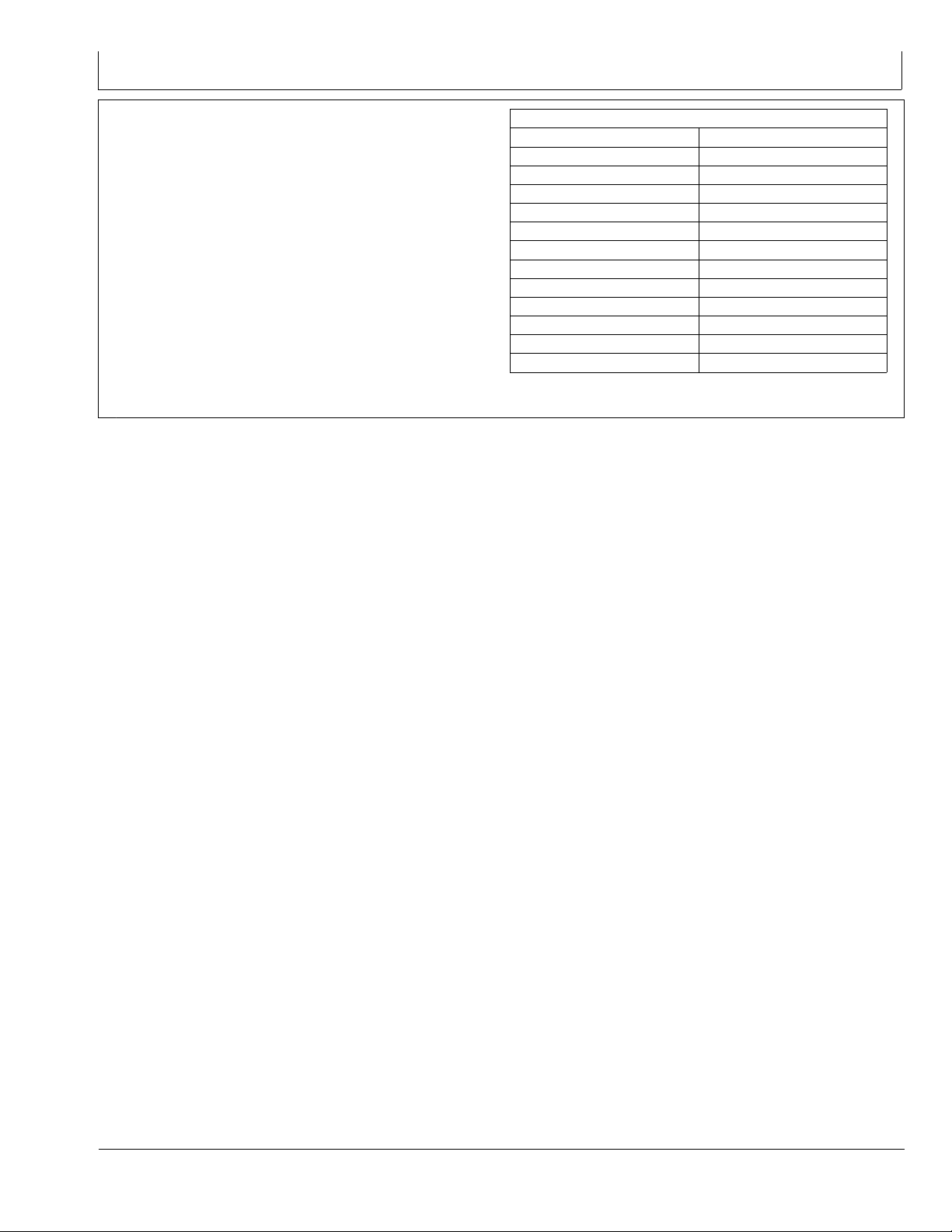
Machine Controller Compatibility
If installing iGrade™ on a machine in serial number
ranges listed in table, contact a John Deere dealer to
determine if any machine controllers require updates
before operating iGrade™.
iGrade is a trademark of Deere & Company
Machine Controller Compatibility
Machine Model
8100 -021245
8200 -021030
8300 -021780
8400 -022341
8100T -902028
8200T -902047
8300T -902166
8400T -902636
9100 -10365
9200 -10849
9300 -10928
9400 -10931
Serial Numbers
RW00482,0000261 -19-11FEB14-1/1
10-3
031214
PN=11
Page 12
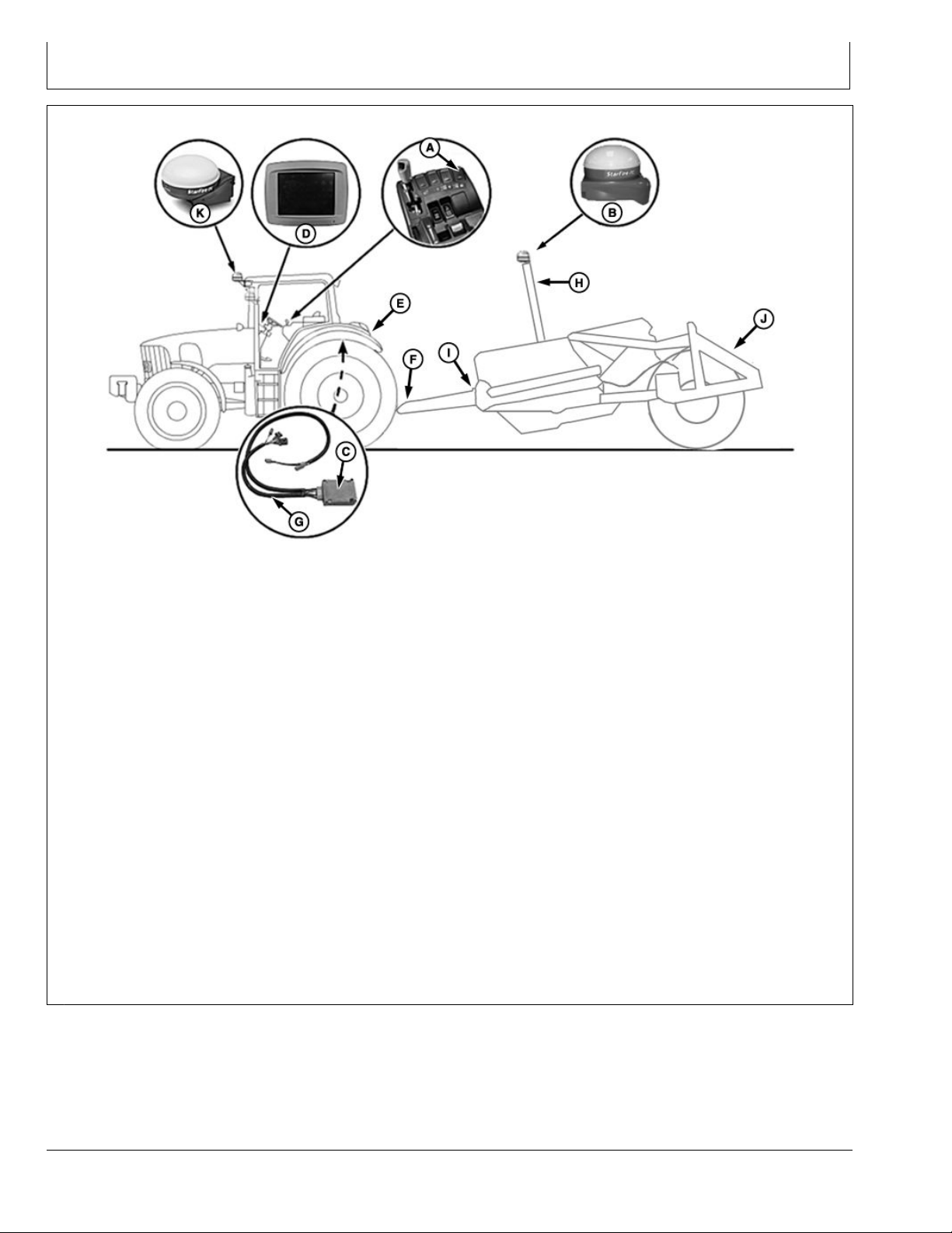
iGrade™ Components
System Components
A—SCV Control Lever
B—StarFire™ RTK Receiver with
Deluxe Shroud
C—Application Controller
Set SCV control lever (A) to AUTO or Actively
•
Controlling (AC) mode.
StarFire™ RTK Receiver (B) communicates elevation
•
of blade height to application controller (C). Receivers
require an RTK activation and radio installed for each
implement receiver and for each machine receiver
using Distance Trip and Max Cut.
Application controller calculates desired elevation
•
information from operator inputs entered in to display
(D).
SCV controller receives instructions from application
•
controller to automate blade height.
Constant adjustments are made to keep height at
•
targeted grade elevation.
Constant power harness (E) connects to convenience
•
outlet. Harness is routed to rear of cab where it
connects to front extension harness (F) and application
controller harnesses (G).
Front extension harness is available in two different
•
lengths 3 m (9.8 ft.) and 10 m (32.8 ft.). Harness
StarFire is a trademark of Deere & Company
D—Display
E—Constant Power Harness
F— Front Extension Harness
G—Application Controller
Harness
H—Implement Receiver
Application Harness
I— Center Extension Harness
J— Rear Extension Harness
connects to constant power harness and ISO implement
connector. Harness is routed along frame of machine
and connects to implement receiver application harness
(H).
If needed, center extension harness (I) extends
•
the distance between front extension harness and
implement receiver application harness. Harness is
available in two lengths 2 m (6.6 ft.) and 8 m (26.2 ft.).
Implement receiver application harness connects to
•
front extension harness and is routed up mast to
implement receiver.
NOTE: If a rear extension harness (J) is not used, a
terminator is needed at end of harness.
Rear extension harness (optional) provides ISO 9-pin
•
connector on rear of scraper.
K—StarFire™ RTK Receiver
RW00482,0000228 -19-11FEB14-1/1
PC18262 —UN—19DEC13
15-1
031214
PN=12
Page 13
SCV Setup
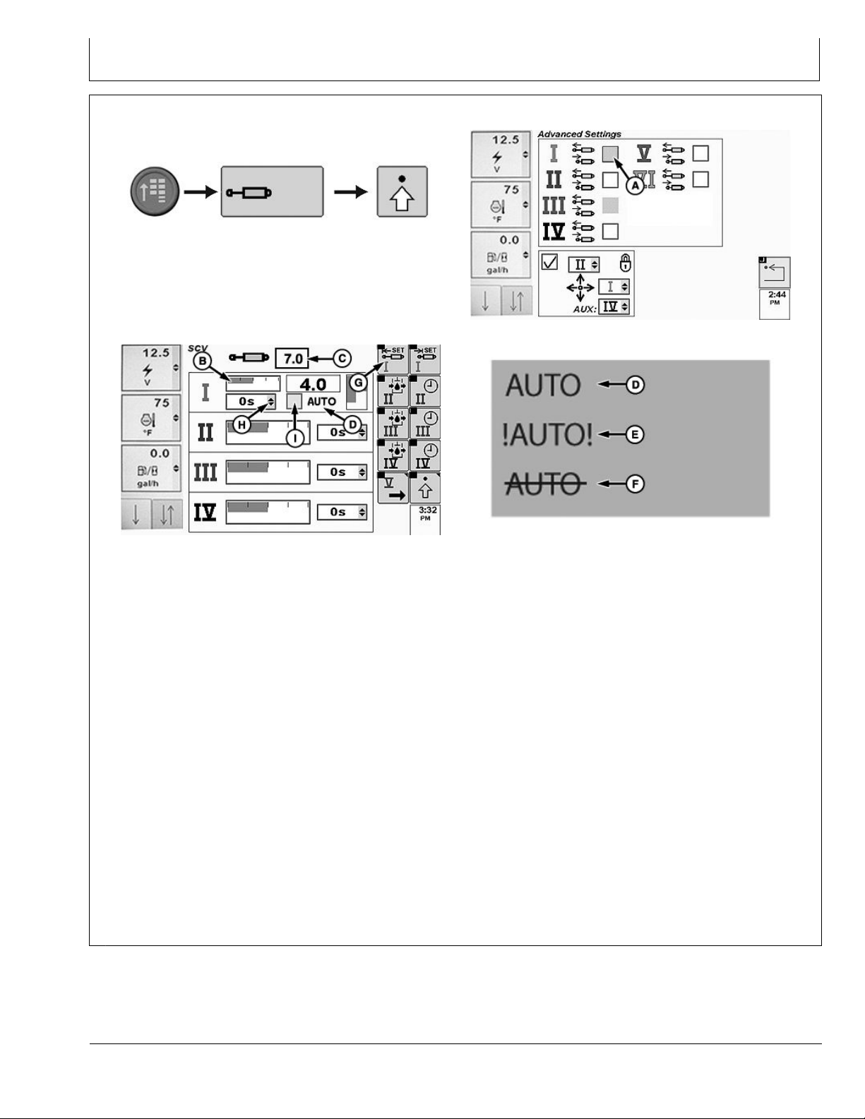
Configure SCVs On CommandCenter™ - Auto Mode
RXA0117610 —UN—10JUN11
CommandARM™ Menu Button > SCV Softkey > Ad-
A—Independent Mode Checkbox
B—Detent Flow Bar Graph
C—Detent Flow Value Box
vanced Settings Softkey
SCV Home Page
D—Auto Status Indicator (Normal
Operation)
E—Auto Status Indicator (Fault
Identified)
To use Auto mode, application controller must be installed
and connected to machine. When connected through
CAN Bus or implement connector, SCV(s) automatically
enter feature mode. SCV Home page with feature option
displays for selected SCVs. On Advanced Settings page,
specified SCV independent mode checkbox (A) is grayed
out.
1. Connect implement to machine.
2. Select Menu button.
3. Select SCV softkey.
SCV Advanced Settings Page
PC18245 —UN—20DEC13
Auto Mode Indicators
F— Auto Status Indicator (Turned
Off)
G—Extend Set Softkey
H—Auto Mode Checkbox
I— Detent Time Drop-down Menu
inoperable. AUTO with a strike through it (F)
indicates auto mode is not active.
5. Select Extend Set softkey (G) to navigate to detent flow
bar graph. Select Confirm button to highlight. Rotate
thumb wheel to adjust flow, then select Confirm button.
NOTE: Detent time drop-down (H) can only be adjusted
when auto mode checkbox (I) is unchecked.
If auto mode checkbox is checked, detent
time cannot be adjusted. Use standard mode
when adjusting detent time.
PC18244 —UN—17DEC13
PC18246 —UN—19DEC13
4. Select Advanced Settings softkey.
NOTE: Bar graph (B) depicts detent flow. Amount of
detent flow is shown in box (C).
AUTO (D) indicates normal auto mode operation.
!AUTO! (E) indicates a fault and auto mode is
CommandARM is a trademark of Deere & Company
6. To adjust detent, rotate thumb wheel to auto mode
checkbox to left of AUTO, then select Confirm button.
When checkbox is unselected, AUTO displays with a
strike through it.
RW00482,00001D4 -19-11FEB14-1/1
20-1
031214
PN=13
Page 14
SCV Setup
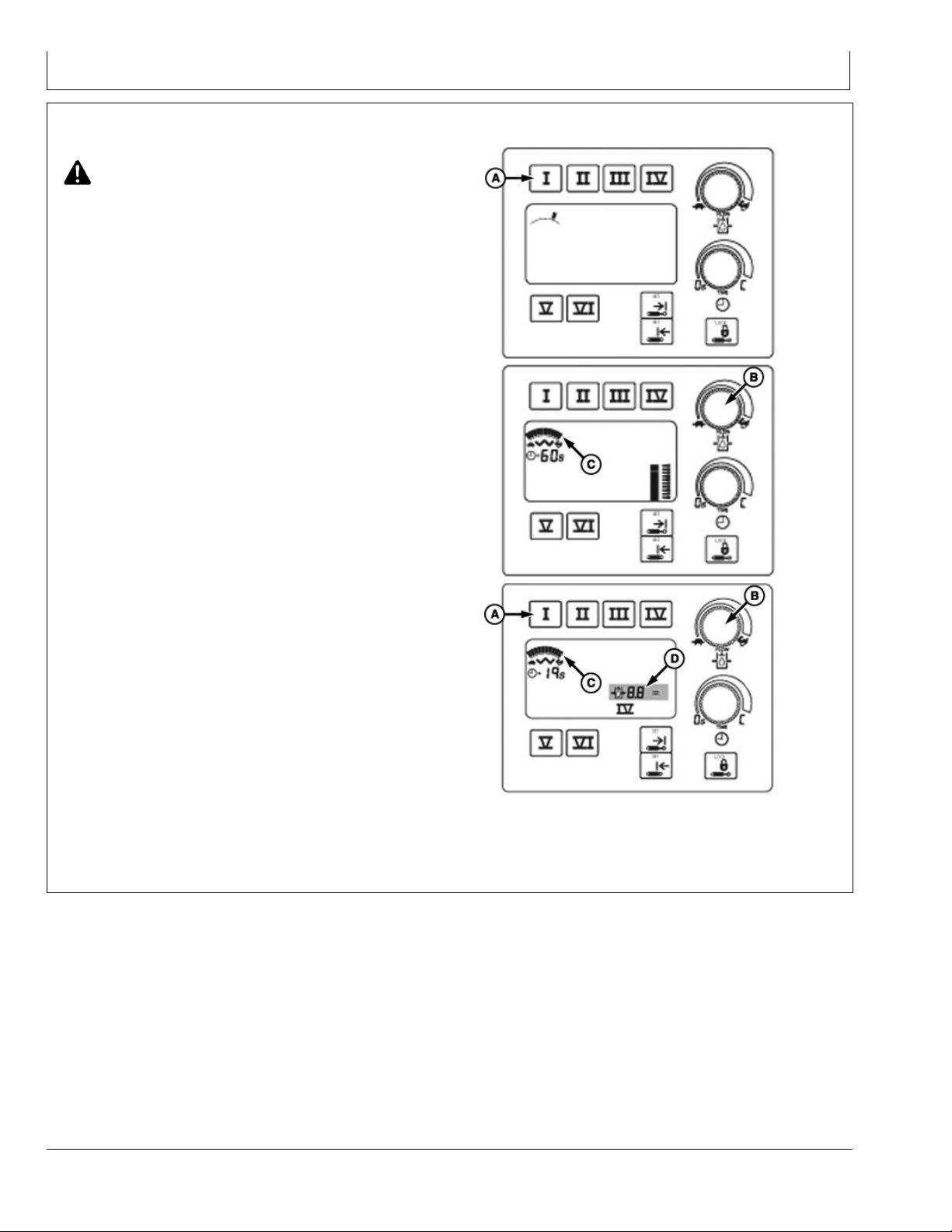
Adjust SCV Flow Rate
CAUTION: Excessive operating speed can cause
damage or injury. Full extension or retraction of
cylinder should take at least 2 seconds.
Adjust rate of operation for each job. Rate should be slow
enough to be safe, yet fast enough to be practical.
Change flow setting as follows:
1. Press selected SCV switch (A). Display below touch
switch shows previous rate of flow.
NOTE: To provide operator with additional indication
of command setting, as operator “clicks” flow
knob (B) through the flow settings, the display
will increase or decrease the number of multiple
line increments as the flow changes.
2. Turn flow rate knob clockwise (rabbit) to increase
flow or counterclockwise (turtle) to decrease flow.
Flow setting is shown on bar graph display (C) when
adjustments are made.
NOTE: SCV can be operated to observe flow rate while
in adjustment mode. Reduced cylinder cycle times
and (or) a reduction in motor speed may result if
total flow demand exceeds available pump flow.
SCV FLOW OUTPUT (APPROXIMATE)
Flow
SCV Flow Settings L/min.
a
0.1
1.0 3.6 1.0
2.0 7.2 1.9
3.0 10.2 2.7
4.0 14.4 3.8
5.0 19.2 5.0
6.0 24.0 6.4
7.0 31.2 8.2
8.0 39.6 10.5
9.0 65.4 17.2
a
0.1 = Minimum Flow Setting
10.0 114 30.0
— —
gpm
A—SCV Switch
B—Flow Rate Knob
PC18357 —UN—13JAN14PC18358 —UN—13JAN14PC18359 —UN—13JAN14
C—Bar Graph Display
D—Multiple Dashes
RW00482,0000267 -19-10FEB14-1/1
20-2
031214
PN=14
Page 15
SCV Setup
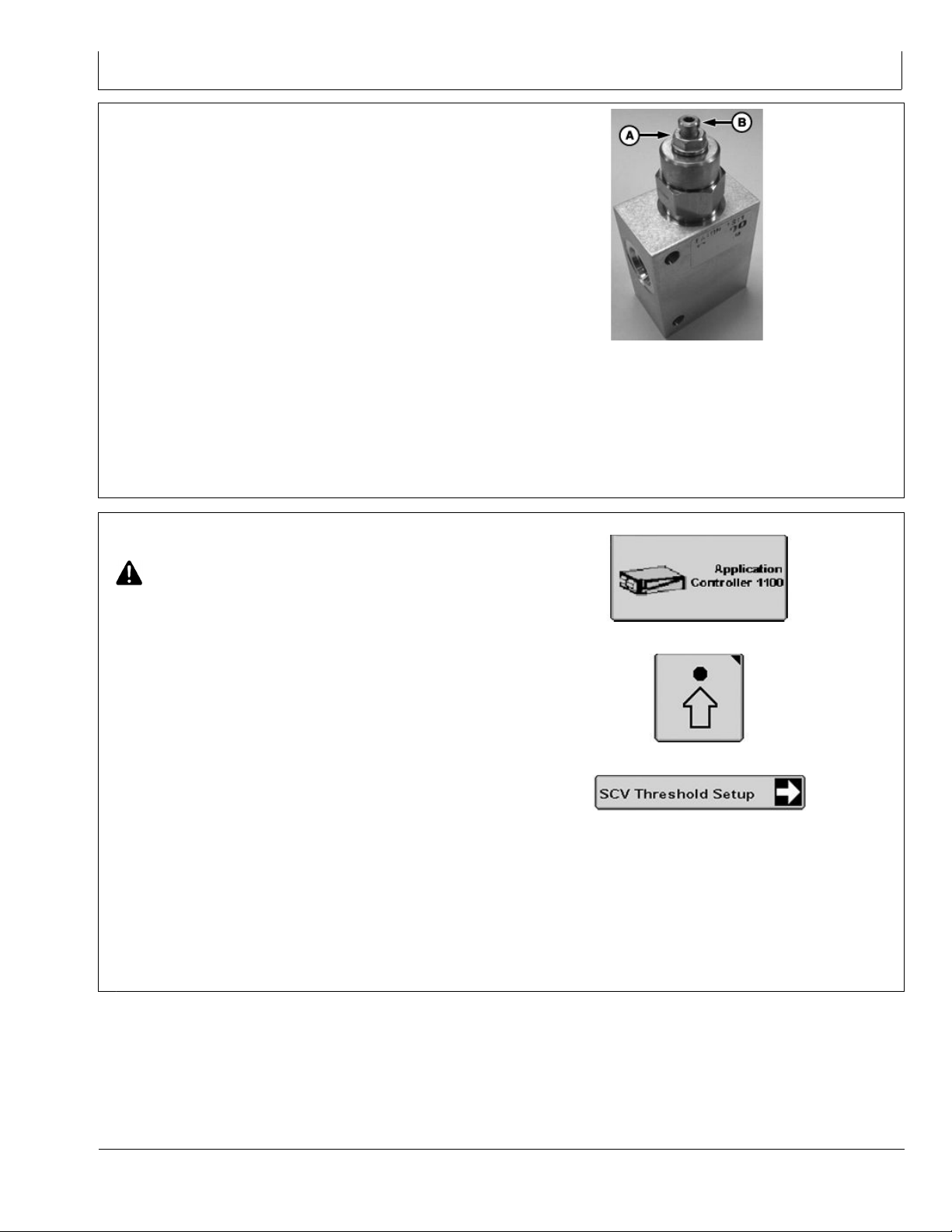
Adjust Valve
NOTE: Flow rates between 11–30 L/min. (3—8
gpm) are recommended.
If hydraulic flow rate is adjusted, complete
SCV threshold calibration test.
1. Adjust hydraulic flow on machine to operators
preference, then adjust valve.
2. Loosen lock nut (A) on valve cartridge.
3. Use 1/4 turn increments to adjust valve. If implement is:
erratic or moves too fast, turn cartridge clockwise
•
until implement reaches desired operation.
slow or not responsive, turn cartridge
•
counterclockwise until implement reaches desired
operation.
A—Lock Nut
PC14814 —UN—29MAR12
B—Valve Cartridge
NOTE: Torque lock nut to 20—25 N·m (15–18 lb.-ft.).
4. Tighten lock nut on valve cartridge.
Calibrate SCV Thresholds
CAUTION: To avoid serious injury, keep area
around equipment clear. This procedure
requires machine to move forward.
Implement will move during calibration.
NOTE: Anytime an adjustment to system is made, such
as SCV hydraulic flow rate or counterbalance valve
adjustment, calibrate SCV threshold.
SCV threshold calibration is necessary for optimal
performance. Perform SCV threshold calibration each
time Application Controller with iGrade™ is installed on
a different machine. Without SCV threshold calibration,
scraper may move significantly faster in one direction,
undercompensate, overcompensate, or not perform as
expected due to hydraulic limitations.
To calibrate SCV, machine must move faster than 0.5
km/h (0.3 mph) to initiate hydraulic flow for SCV control.
Select SCV (1 or 3) then AC mode as indicated on SCV
control display. Implement does not need to be in working
(lowered) position to calibrate.
If acceptable performance is not reached after
adjusting valve, adjust hydraulic flow rate on machine
then readjust valve.
RW00482,00001EB -19-09JAN14-1/1
PC14926 —UN—27APR12
PC12961 —UN—29AUG11
PC18039 —UN—11NOV13
Application Controller 1100 Button
Setup Softkey
SCV Threshold Setup Button
2. Select Setup softkey.
3. Select SCV Threshold Setup button.
1. Select Application Controller 1100 button.
iGrade is a trademark of Deere & Company
Continued on next page RW00482,0000259 -19-06MAR14-1/2
20-3
031214
PN=15
Page 16
SCV Setup
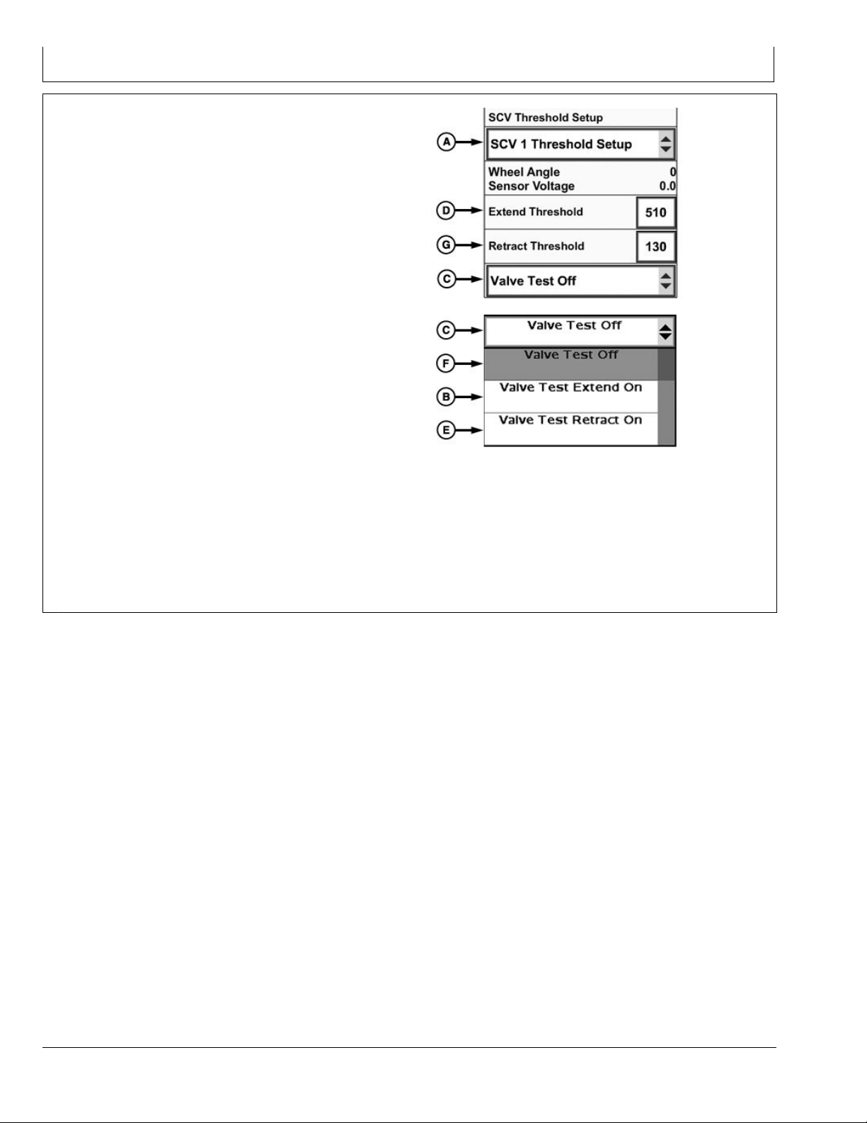
4. Select SCV being used from SCV Threshold Setup
drop-down (A).
5. Select Valve Test Extend On (B) from Valve Test
drop-down menu (C).
6. Place SCV lever into detent.
NOTE: Extend raises implement and retract
lowers implement.
7. Adjust Extend Threshold value (D) to lowest setting
that produces a steady, consistent motion.
If scraper height does not change, increase
•
Extend Threshold value, until minimal movement is
achieved.
If scraper moves quickly or erratically, decrease
•
Extend Threshold.
Repeat procedure as required to obtain a smooth,
•
constant change in scraper height.
Extend and Retract thresholds valves may have
•
different values.
8. Select Valve Test Retract On (E) from drop-down.
9. Repeat adjustment procedures used in Valve Test
Extend calibration.
10. Turn Valve Test Off (F) when calibration is complete.
If SCV flow rate is too high, scraper could be overly
sensitive and cause washboard effect.
SCV Threshold Setup
Valve Test Drop-down Menu
A—SCV Threshold Setup
Drop-down Menu
B—Valve Test Extend On
C—Valve Test Drop-down Menu
D—Extend Threshold
PC18407 —UN—23JAN14
PC18248 —UN—17DEC13
E—Valve Test Retract On
F— Valve Test Off
G—Retract Threshold
If SCV flow rate is too low, control and load limit
functionality could be impaired or limited.
RW00482,0000259 -19-06MAR14-2/2
20-4
031214
PN=16
Page 17

Basic Operation
Basic Operation
SCV controller is set to AC mode (A) by placing SCV
•
into detent position.
iGrade™ calculates elevation error using location of
•
StarFire™ Receiver(s) in relation to a desired elevation
set by operator.
When AUTO control is enabled and activated, and if
•
implement requires height adjustment to bring it back
on desired grade, a signal is sent from iGrade™,
through Application Controller harness, to machine
SCV controller.
SCV controller communicates instructions for sending
•
hydraulic fluid to implement control cylinder.
Entire process returns to first step to continually monitor
•
for any implement elevation error. Constant adjustments
are made to keep implement on desired grade.
NOTE: AUTO (B) indicates normal auto mode
operation. !AUTO! (C) indicates a fault and auto
mode is inoperable. AUTO with a strike through
it (D) indicates auto mode is not active.
If operating a machine with a CommandCenter™
•
display, select AUTO by placing a check in checkbox (E).
PC18217 —UN—05DEC13
SCV Controller Set in AC Mode
A—SCV Controller Set in AC
Mode
B—AUTO Status Indicator
(Turned On)
C—AUTO Status Indicator
(Fault Identified)
D—AUTO Status Indicator
(Turned Off)
E—AUTO Mode Checkbox
iGrade is a trademark of Deere & Company
StarFire is a trademark of Deere & Company
CommandCenter is a trademark of Deere & Company
F— Detent Time Drop-down
Menu
G—Detent Flow Bar Graph
H—Detent Flow Value Box
I— Extend Set Softkey
PC18218 —UN—05DEC13
SCV Homepage
PC18219 —UN—05DEC13
RW00482,000025E -19-20FEB14-1/1
25-1
031214
PN=17
Page 18

Basic Operation
Engage iGrade™
1. Set up control type display.
2. Using SCV controls, place SCV control lever (A) to
forward detent position to activate elevation control.
Engage SCV levers (A and B) if using dual scrapers.
3. Select SCV button on TouchSet™ display.
4. Verify EC on TouchSet™ display changes to AC (C).
If operating a machine with CommandCenter™
display, verify AUTO off (D) changes to AUTO on (E).
(For more information on CommandCenter™ SCV
controls refer to machine Operator's Manual.)
iGrade™ begins acquiring desired elevation immediately
after SCV is placed into forward detent if machine is
moving faster than 0.5 km/h (0.32 mph) and control type
has been properly set up.
A—SCV 1 Control Lever
B—SCV 3 Control Lever
C—AC Mode
D—AUTO Status Indicator
(Turned Off)
E—AUTO Status Indicator
(Turned On)
PC18249 —UN—19DEC13PC18250 —UN—20DEC13PC18251 —UN—20DEC13
TouchSet is a trademark of Deere & Company
CommandCenter is a trademark of Deere & Company
iGrade is a trademark of Deere & Company
25-2
RW00482,000025A -19-11FEB14-1/1
031214
PN=18
Page 19

Basic Operation
Dual Scrapers
Every receiver on CAN Bus is shown in display menu.
Each receiver button contains receiver serial number and
location (machine or implement).
Implement receivers are shown on display when they are
connected to receiver application harness. When using
dual scrapers, two implement receiver buttons are shown.
For dual scraper applications, SCV 1 must control front
scraper and SCV 3 must control rear scraper. Verify on
Implement receiver pages that each implement receiver
correlates to respective SCV movement.
NOTE: It is crucial to system performance to use lowest
serial numbered receiver on front scraper and
highest serial numbered receiver on rear scraper.
Dual scrapers require a receiver mounted on each
•
scraper.
Implement harnesses accommodate multiple receivers.
•
NOTE: Stored planes or grades are same for both
SCVs when using same control type. Setting
benchmark or zero point for front scraper
also sets rear scraper.
For dual scraper applications, threshold
calibrations must be performed for both
SCV 1 and SCV 3.
Selecting same control type for SCV 1 and SCV 3
•
allows dual scrapers to control same plane or grade.
iGrade is a trademark of Deere & Company
StarFire is a trademark of Deere & Company
Dual Scrapers
For best performance:
Mount receiver mast on center line of implement over
•
control point.
Receiver offsets can be entered for iGrade™. When
•
using multiple implements, install receivers at same
height from blade to receiver. If needed, adjust scraper
offsets for application purposes.
NOTE: When operating dual scrapers, use same model
of receiver on both implements. Only use two
StarFire™ iTC Receivers or two StarFire™ 3000
Receivers. Receivers calculate elevation differently.
When operating SWP+, use same receivers
(StarFire™ iTC or StarFire™ 3000) for collecting
elevation data for ditching operation.
RW00482,0000287 -19-11FEB14-1/1
PC17567 —UN—12AUG13
25-3
031214
PN=19
Page 20

Basic Operation
Load Limiting
Load Limiting raises scraper when Engine Speed
Threshold or Slip Threshold are exceeded to protect
machine. StarFire™ Receivers are required on both
machine and implement for full Load Limiting functionality.
Load Limiting auto mode functions with Grade Control,
Remote Control, and Plane Control.
1. Select Application Controller 1100 from main menu.
2. Select Main softkey.
3. Select Plane Control Setup, Remote Control Setup, or
Grade Control Setup button.
4. Select Load Parameter Setup button.
5. Enter Elevation Control Sensitivity.
Elevation Control Sensitivity allows operator to
adjust up and down movement of implement.
Elevation Control Sensitivity defaults to 2000, and
is adjustable between 10—10,001. For slower and
less aggressive up and down implement movement,
decrease value. For faster and more aggressive up
and down implement movement, increase value.
PC14926 —UN—27APR12
PC13072 —UN—16NOV10
PC18047 —UN—12NOV13
PC18049 —UN—12NOV13
PC18050 —UN—12NOV13
Application Controller 1100 Button
Main Softkey
Plane Control Setup Button
Load Parameter Setup Button
Elevation Control Sensitivity
StarFire is a trademark of Deere & Company
6. Select Load Limit Setup button.
7. Enable Load Limiting by selecting Load Limiting On
from drop-down (A). Disable Load Limiting by selecting
Load Limiting Off from drop-down.
8. Enter Engine Speed Threshold (B) and Slip Threshold
(C).
If either threshold is reached, system raises blade
until acceptable conditions are restored. Slip requires
machine receiver to function as ground speed source.
Engine Speed defaults to 1500 and Slip defaults to
15%.
A—Load Limiting Drop-down
Menu
B—Engine Speed Threshold
C—Slip Threshold
D—Load Limit Diagnostics
E—Back Button
RW00482,0000284 -19-11FEB14-1/2
PC18059 —UN—12NOV13
Load Limit Setup Button
PC18060 —UN—12NOV13
Load Limit Settings
RW00482,0000284 -19-11FEB14-2/2
25-4
031214
PN=20
Page 21

Basic Operation
Max Cut
NOTE: If using SF2 signal on machine receiver, Distance
Trip does not function and Max Cut must be disabled.
Max Cut allows operator to set a maximum amount of
cut implement takes in a single pass. Max Cut requires
machine and implement to have a StarFire™ Receiver
with RTK signal.
1. Select Application Controller 1100 button.
2. Select Main softkey.
3. Select Plane Control Setup, Remote Control Setup, or
Grade Control Setup button.
4. Select Load Parameter Setup button.
StarFire is a trademark of Deere & Company
PC14926 —UN—27APR12
PC13072 —UN—16NOV10
PC18047 —UN—12NOV13
PC18049 —UN—12NOV13
Application Controller 1100 Button
Main Softkey
Plane Control Setup Button
Load Parameter Setup Button
RW00482,0000285 -19-11FEB14-1/2
5. Enter Elevation Control Sensitivity.
Elevation Control Sensitivity allows operator to
adjust up and down movement of implement.
Elevation Control Sensitivity defaults to 2000, and
is adjustable between 10—10,001. For slower and
less aggressive up and down implement movement,
decrease value. For faster and more aggressive up
and down implement movement, increase value.
6. Select Max Cut Setup button.
7. Enable Max Cut by selecting Max Cut Enabled from
drop-down (A). Disable Max Cut by selecting Max Cut
Disabled from drop-down.
8. Operate implement manually to desired Max Cut
depth and select Set Max Cut Here button (B). Select
Shift Max Cut Down button (C) or Shift Max Cut Up
button (D) to increase or decrease maximum cut depth
in increments of 2 cm (0.79 in.).
A—Max Cut Drop-down Menu
B—Set Max Cut Here
C—Set Max Cut Down
D—Shift Max Cut Up
E—Back Button
PC18061 —UN—12NOV13
PC18062 —UN—12NOV13
Elevation Control Sensitivity
Max Cut Setup Button
PC18063 —UN—12NOV13
Max Cut Settings
RW00482,0000285 -19-11FEB14-2/2
25-5
031214
PN=21
Page 22

Basic Operation
Offsets
iGrade™ allows user to preset step size for shifting offsets
for Remote Control and Plane Control. For dual scraper,
setting offsets step size changes step size for both SCV 1
and SCV 3.
1. Select Application Controller 1100 button.
2. Select Main softkey.
3. Select Remote Control Setup or Plane Control Setup
for SCV 1. If using dual scrapers, selecting SCV 1 or
SCV 3 sets the same step size for both SCVs.
4. For Plane Control, select Parameter Setup. For
Remote Control, skip this step.
5. Select Offsets Setup.
6. Enter Offsets Step Size (A).
7. For dual scrapers, scraper 2 offset may be set higher
or lower than scraper 1.
1. Enter Scraper 2 Offset (B).
2. Select Scraper 2 Higher or Scraper 2 Lower from
drop-down menu (C).
A—Offsets Step Size
B—Scraper 2 Offset
C—Scraper 2 Drop-down Menu
PC14926 —UN—27APR12
PC13072 —UN—16NOV10
PC18047 —UN—12NOV13
PC18471 —UN—10FEB14
PC18474 —UN—10FEB14
PC18473 —UN—10FEB14
Application Controller 1100 Button
Main Softkey
Plane Control Setup Button
Remote Control Setup Button
Parameter Setup Button
iGrade is a trademark of Deere & Company
Offsets Setup Button
PC18472 —UN—10FEB14
Offsets
RW00482,0000286 -19-18FEB14-1/1
25-6
031214
PN=22
Page 23

Remote Control—Surface Water Pro™ Plus
Theory of Operation
SWP+ is an advanced ditching program that generates a
“best fit drain.” SWP+ calculates the most effective drain in
a field while moving the least amount of soil. Information
is generated from vertical GPS signals calculated from
the StarFire™ Receiver. SWP+ requires an RTK enabled
receiver on implement and SF2 or RTK enabled receiver
on machine.
StarFire is a trademark of Deere & Company
Apex is a trademark of Deere & Company
Control Selection
1. Select Setup softkey.
2. Select Control Selection button.
3. Select Remote Control from SCV 1 Control Type
drop-down.
NOTE: Remote Control can utilize dual scrapers. When
utilizing dual scraper functionality, use SCV 1 for
front scraper and SCV 3 for rear scraper.
4. Select Back button.
Remote Control feature automatically controls blade
height to a desired elevation calculated from ditches
created in Apex™ or by SWP+ software on the display.
NOTE: If using SF2 signal on machine receiver, Distance
Trip does not function and Max Cut must be disabled.
RW00482,000024C -19-11FEB14-1/1
PC12961 —UN—29AUG11
PC17972 —UN—07NOV13
PC18065 —UN—12NOV13
Setup Softkey
Control Selection Button
PC17974 —UN—07NOV13
SCV 1 Control Type Drop-down Menu
Back Button
RW00482,00001F1 -19-09JAN14-1/1
30-1
031214
PN=23
Page 24

Remote Control—Surface Water Pro™ Plus
Operation
NOTE: Separate offsets can be placed in Remote Control
Main and on SWP+ Create/Edit Drain page. If
system is not cutting to grade, check both offsets.
Offsets are based on designed ditch, not ground level
(distance off grade, not a maximum cut limit).
(Refer to Surface Water Pro™ Operator Manual for
in-depth information on SWP.)
1. Select Main softkey.
2. Select Remote Control Main button.
After SCV(s) have been placed in detent and AC enabled,
iGrade™ controls blade height to grade.
Offsets are changed in increments.
•
Set Offset—Zero Error (A) takes current error and
•
applies it as an offset to the designed ditch.
Shift offsets are useful when implement is attempting to
•
control an elevation that machine cannot attain. Shift
Offset Up (B) to achievable cut and Shift Offset Down
(C) back to 0 over subsequent passes.
A—Set Offset—Zero Error
B—Shift Offset Up
C—Shift Offset Down
PC13072 —UN—16NOV10
PC18066 —UN—12NOV13
Main Softkey
Remote Control Main Button
PC18067 —UN—12NOV13
Remote Control Main
Surface Water Pro is a trademark of Deere & Company
iGrade is a trademark of Deere & Company
30-2
PC12524 —UN—23MAR10
SWP+ Create/Edit Drain Page
RW00482,00001F2 -19-19FEB14-1/1
031214
PN=24
Page 25

Remote Control—Serial Port
Theory of Operation
The John Deere Application Controller allows the ability
to connect with 3rd Party Software through the use of
a serial connection. This functionality may be useful
if you currently use an additional software package to
provide capabilities such as cut/fill mapping and would
like the John Deere Application Controller to connect and
communicate with this software. After a serial connection
Message Definition
The John Deere Application Controller can use two types
of command messages.
Elevation Setpoint
The 3rd Party software can send a commanded elevation
to the Application Controller. The implement will be
controlled such that the implement receiver elevation
attempts to match the setpoint elevation. The message
protocol is as follows:
$JD,ELEV, 274.32 Carriage Return
Where the elevation value is in meters and can handle
two decimal places. Ensure that there are no spaces and
that the carriage return ends the message.
is established, the 3rd Party Software can send setpoint
commands that the Application Controller will use to
automatically control elevation on an implement. This is
accomplished using the serial port on the controller and
the operation specific message protocols. The controller
is also capable of retransmitting GPS data to the third
party software using the same serial port, eliminating the
need for an additional connection.
JS56696,00009A2 -19-25APR11-1/1
Depth Setpoint
The 3rd Party software can send a commanded depth to
the Application Controller. The implement will be controlled
such that the implement receiver elevation attempts
to match the setpoint depth. When using this mode a
machine receiver will be needed to calculate the elevation
of the ground surface. Offsets will need to be used to
account for height differences between the machine and
implement receivers. The message protocol is as follows:
$JD,DEPTH, 1.54 Carriage Return
Where the depth value is in meters and can handle two
decimal places. Ensure that there are no spaces and that
the carriage return ends the message.
CZ76372,0000236 -19-15NOV10-1/1
Serial Port Hardware
Remote Control harnesses for third-party software must
follow these guidelines.
NOTE: Contact your John Deere dealer to order parts.
Harness does not come assembled.
Part Number Description
57M9804
57M8164
—
—
Mating Connector to Controller Harness
Pins for 57M9804
DB9 Plug Connector Assembly
2.5 m (8 ft.) of 0.5 mm
2
(20 AWG) wire
PC17350 —UN—06NOV13
Serial Port Wiring Pinouts
Quantity
1
3
1
3
RW00482,00001EC -19-11FEB14-1/1
35-1
031214
PN=25
Page 26

Remote Control—Serial Port
Serial Port Setup
1. Select Setup softkey.
2. Select Serial Port Setup button.
NOTE: Baud Rate is the data transfer rate used
for commands from third-party software as
well as GPS position data going to third-party
software, if applicable.
3. Select Baud Rate from drop-down menu (A).
4800
•
9600
•
19200
•
38400
•
4. If utilizing Application Controller to retransmit
StarFire™ implement position data through serial
port, select National Marine Electronics Association
(NMEA) messages needed by third-party software
from drop-down (B).
NOTE: If not using Application Controller to send
StarFire™ implement position data through
serial port, select NMEA Off.
NO NMEA
•
NMEA GGA
•
NMEA GGA, GSA
•
NMEA GGA, GSA, RMC
•
NMEA ALL
•
5. If utilizing Application Controller to retransmit
StarFire™ implement position data though serial port,
select data frequency needed by third-party software
from drop-down (C).
1 Hz
•
5 Hz
•
6. If utilizing third-party software to show an as applied
map, Last Altitude allows a third receiver on last
StarFire is a trademark of Deere & Company
PC12961 —UN—29AUG11
PC18252 —UN—17DEC13
A—Baud Rate Drop-down
Menu
B—NMEA Message Drop-down
Menu
C—NMEA Rate Drop-down
Menu
Setup Softkey
Serial Port Setup Button
Serial Port Setup
D—Last Altitude Drop-down
Menu
E—Back Button
implement for elevation data. John Deere does
not have an approved setup for this application.
Customer must determine best installation setup for
this application.
RW00482,00001ED -19-11FEB14-1/1
PC18071 —UN—13NOV13
35-2
031214
PN=26
Page 27

Remote Control—Serial Port
Control Selection
1. Select Setup softkey.
2. Select Control Selection button.
NOTE: Remote Control can utilize dual scrapers. SCV
1 must be used for front scraper and SCV 3
for rear scraper. When utilizing dual scraper
functionality, change SCV Control Type for both
SCV 1 and SCV 3 to Remote Control.
3. Select Remote Control from SCV 1 control type
drop-down (A).
4. Select Back button (B).
A—SCV 1 Control Type
Drop-down Menu
B—Back Button
PC12961 —UN—29AUG11
PC17972 —UN—07NOV13
Setup Softkey
Control Selection Button
PC18072 —UN—10DEC13
Control Selection
RW00482,00001F3 -19-28JAN14-1/1
Operation
Offsets are based on desired command from third-party
software, not ground level (distance off grade, not a
maximum cut limit).
1. Select Main softkey.
2. Select Remote Control Main button.
After SCV(s) have been placed in detent and AC enabled,
iGrade™ controls blade height to grade.
Set Offset—Zero Error (A) takes current error and
•
applies it as an offset to desired command.
Shift offsets are useful when implement is attempting to
•
control an elevation that machine cannot attain. Shift
Offset Up (B) to achievable cut and Shift Offset Down
(C) back to 0 over subsequent passes.
When setting zero point in Remote Control a value is
displayed next to Offset. This value represents difference
between surveyed receiver elevation and elevation of
front implement receiver when zeroing error.
A—Set Offset—Zero Error
B—Shift Offset Up
iGrade is a trademark of Deere & Company
C—Shift Offset Down
PC13072 —UN—16NOV10
PC18066 —UN—12NOV13
Main Softkey
Remote Control Main Button
PC18067 —UN—12NOV13
Remote Control Main
RW00482,00001D6 -19-11FEB14-1/1
35-3
031214
PN=27
Page 28

Grade Control
Theory of Operation
Grade Control automatically controls scraper to a defined
slope over a GPS distance. Grade may be defined by the
Grade Calculator or operator inputs (slope and direction)
at point of origin on slope. Slope direction is calculated
based on GPS logic. North corresponds to an angle of 0°
and 360°. Angles increase clockwise in degrees with a full
circle equaling 360°. Direction of travel does not affect
grade and system automatically fills or cuts during uphill
or downhill operation. The slope causes an increase in
elevation over a given distance for uphill operations and
decreases in elevation for downhill operations.
PC18421 —UN—28JAN14
A—Point of Origin (Start Point)
B—Starting Grade
C—Finished Grade
D—Slope %
E—Area Cut (Dirt Removed)
F— Area Filled (Dirt Added)
G—North = 0°/360°
H—East = 90°
I— South = 180°
J— West = 270°
K—Slope Direction (Degrees)
Grade Calculator
1. Select Setup softkey.
2. Select Control Selection button.
3. Select Grade Control for SCV 1 (or SCV 1 and SCV
3 for dual scrapers).
4. Select Main softkey.
5. Select Grade Control Setup button.
PC12961 —UN—29AUG11
PC17972 —UN—07NOV13
PC18075 —UN—13NOV13
PC13072 —UN—16NOV10
RW00482,0000271 -19-11FEB14-1/1
Setup Softkey
Control Selection Button
Grade Control Drop-down Menu
PC18076 —UN—13NOV13
Continued on next page RW00482,0000218 -19-11FEB14-1/2
Main Softkey
Grade Control Setup Button
40-1
031214
PN=28
Page 29

Grade Control
6. Enter Slope (A) if known or use Grade Calculator (B)
to calculate slope.
NOTE: Use front scraper as SCV 1 to define grade
when utilizing dual scrapers.
Grade Calculator (B) records a series of points and
calculates slope to connect end points of recorded path.
Select Start Grade Calculator (C) to reset Grade
•
Calculator, clear any previous data, and take start
position.
Drive to end position and select Stop Grade Calculator.
•
Grade Statistics are displayed on screen.
•
If data appears correct, select Set as Grade Control
•
Slope (D).
Operator must drive same path during operation recorded
with Grade Calculator. If same path is not driven, final
elevation may not match desired or recorded elevation
due to a different distance traveled. Make sure that
scraper remains in a constant position during data
collection (for example: in up position).
PC18077 —UN—10DEC13
Grade Control Setup
A—Slope
B—Grade Calculator
C—Start/Stop Grade Calculator
D—Set as Grade Control Slope
Selecting Grade
After entering desired grade, go to start point for grade
and lower cutting edge.
1. Select Main softkey.
2. Select Grade Control Main button.
3. Select Grade Direction (A) machine will travel (uphill
or downhill).
NOTE: Uphill is a positive slope and downhill is
a negative slope.
4. Select Start Grade (B).
Front scraper sets grade. For dual scrapers, raise front
pan when full and place rear pan into auto mode. If pan(s)
are full before grade is complete, select Pause button (C)
to stop grade and empty pan(s). Return to spot grade
was paused and lower front scraper cutting edge back to
desired grade. Select Resume and continue grade. Pause
and resume as needed until desired grade is completed.
PC13072 —UN—16NOV10
PC18409 —UN—24JAN14
PC18078 —UN—10DEC13
Grade Calculator
RW00482,0000218 -19-11FEB14-2/2
Main Softkey
Grade Control Main Button
A—Grade Direction
B—Start Grade
C—Pause/Resume
40-2
PC18410 —UN—24JAN14
Grade Control Main
RW00482,000026C -19-19FEB14-1/1
031214
PN=29
Page 30

Plane Control
Theory of Operation
Plane Control automatically controls scraper to cut to
defined plane. Defined planes can be a single sloped
plane or a dual sloped plane. Planes may be defined by the
Plane Calculator or operator inputs (slope and direction)
for a set origin point on plane. Slope direction is calculated
based on GPS logic and in the down slope direction. North
corresponds to an angle of 0° and 360°. Angles increase
clockwise in degrees with a full circle equaling 360°. The
system allows operator to set up two independent planes
that can be used as a cut and a fill plane.
The Plane Calculator can create a best fit plane based
on recorded elevation data. Once all data has been
collected, a best fit plane is created.
A—North = 0°/360°
B—East = 90°
C—South = 180°
D—West = 270°
E—Slope 0.12%, Down Slope
Direction 160°
F— Slope1 0.12%, Down Slope
Direction1 270°
G—Slope2 0.14%, Down Slope
Direction2 180°
PC18420 —UN—28JAN14
Slope Direction
Single Slope
Dual Slope
PC18411 —UN—12FEB14
PC18412 —UN—28JAN14
RW00482,000026D -19-12FEB14-1/1
45-1
031214
PN=30
Page 31

Plane Control
Control Selection
1. Select Setup softkey.
2. Select Control Selection Button.
3. Select Plane Control from SCV 1 Control Type
drop-down menu.
NOTE: For ease of instruction, this manual uses SCV 1
for the iGrade™ system. Turn other SCV Controls
to OFF unless using dual scrapers.
iGrade is a trademark of Deere & Company
Select Active Plane
1. Select Main softkey.
2. Select Plane Control Setup button.
PC12961 —UN—29AUG11
PC17972 —UN—07NOV13
PC18413 —UN—27JAN14
SCV Control Type Drop-down Menu
PC13072 —UN—16NOV10
Setup Softkey
Control Selection Button
RW00482,0000262 -19-12FEB14-1/1
3. Select active plane from Plane Control Setup
drop-down menu.
NOTE: Both SCVs control same active plane if same
control type is selected for both SCVs.
PC18047 —UN—12NOV13
PC18414 —UN—27JAN14
Plane Control Setup Drop-down Menu
Main Softkey
Plane Control Setup Button
RW00482,000026E -19-26JAN14-1/1
45-2
031214
PN=31
Page 32

Plane Control
Single Slope Plane
1. Select plane to define from Plane Control Setup
drop-down menu.
2. Select Single Slope Entry button.
3. Enter plane Slope (A) and Slope Direction (B) if
known, or use Plane Calculator.
4. Drop scraper on point of origin and select Set Plane
Origin (C).
NOTE: If running dual scrapers, use front scraper
(SCV1) to set plane origin.
A—Slope
B—Slope Direction
C—Set Plane Origin Button
D—North = 0°/360°
E—East = 90°
F— South = 180°
G—West = 270°
H—Slope 0.12%, Down Slope
Direction 160°
PC18414 —UN—27JAN14
PC18415 —UN—27JAN14
Plane Control Setup Drop-down Menu
Single Slope Entry Button
PC18416 —UN—28JAN14
Single Slope Entry
Single Slope
PC18423 —UN—28JAN14
RW00482,000026F -19-12FEB14-1/1
45-3
031214
PN=32
Page 33

Plane Control
Dual Slope Plane
1. Select plane to define from Plane Control Setup
drop-down menu.
2. Select Dual Slope Entry button.
3. Select Dual Slope Input button.
4. Enter plane Slope1 (A), Down Slope Direction1 (B),
plane Slope2 (C), and Down Slope Direction2 (D) if
known, or use Plane Calculator.
NOTE: Slope direction allows operators to define desired
direction of slopes in relation to each other. Slope
directions can be at any angle to one another.
5. Select Dual Slope Setup button to return to Dual Slope
Entry page to set plane origin.
6. Drop scraper to a point on the plane and press Set
Plane Origin button. The plane is created at the
elevation of the set origin.
NOTE: If running dual scrapers, use front scraper
(SCV1) to set plane origin.
A—Slope1
B—Down Slope Direction1
C—Slope2
D—Down Slope Direction2
E—Back Button
F— North = 0°/360°
G—East = 90°
H—South = 180°
I— West = 270°
J— Slope1 0.12%, Down Slope
Direction1 270°
K—Slope2 0.14%, Down Slope
Direction2 180°
PC18414 —UN—27JAN14
PC18417 —UN—27JAN14
PC18419 —UN—27JAN14
Plane Control Setup Drop
Dual Slop Entry Button
Dual Slope Input Button
PC18418 —UN—04FEB14
Dual Slope Input
45-4
PC18422 —UN—28JAN14
Dual Slope
RW00482,0000270 -19-12FEB14-1/1
031214
PN=33
Page 34

Plane Control
Plane Calculator
Theory of Operation
Plane calculator records a series of elevation points
(approximately every 1.5 m [5 ft.]) and stores elevation
data. When data collection is turned off, iGrade™
generates a best fit plane and displays calculated slope
and direction. If given slope and direction look realistic,
select Save to Active Plane button (A). Start (Stop) Data
Collection (B) can continuously record by leaving data
collection on or only record desired points of interest
by turning data collection on and off between points to
generate the best fit plane.
If calculated plane does not appear correct, collect and
save more data points to active plane, or plane data
can be cleared and collection restarted. Plane created
displays in both Single and Dual Sloped Entries pages.
Tips
Use front scraper as SCV 1 to define plane, if utilizing
•
dual scrapers.
Collecting more points results in better accuracy.
•
Scatter data points (do not drive in straight line unless
•
collecting data from the entire area).
Clear plane data at start of every new plane. Uncleared
•
data is applied to current plane.
Edit calculated plane information, if needed, through
•
Single or Dual Slope entry pages after saving created
plane to active plane.
Ensure that scraper remains in a constant position
•
during data collection (for example, in up position).
Plane Calculator assumes a 1:1 cut-fill ratio.
•
Plane Calculator calculates a plane origin based on
•
height of implement receiver during data collection.
Origin can be shifted to an actual on-grade point by
selecting Set Plane Origin button in either Single Slope
or Dual Slope Entry pages or by using offsets.
iGrade is a trademark of Deere & Company
PC18084 —UN—13NOV13
Plane Calculator Button
Plane Calculator
A—Save to Active Plane
B—Start (Stop) Data Collection
1. Select Plane Calculator.
2. If new plane, clear Plane Data (C).
3. Select Start Data Collection to gather data.
4. Turn off data collection and review calculated slope
and heading.
5. If correct, select Save to Active Plane to accept and
enter plane information in both Single and Dual Slope
Entry pages for selected active plane.
C—Clear Plane Data
D—Back Button
RW00482,000021B -19-12FEB14-1/1
PC18365 —UN—13JAN14
Dual Scraper
Dual Scrapers can be used with Plane Control or Grade
•
Control.
Select the same control type for each SCV.
•
Plane setup can be completed with either SCV control.
•
Only one plane is used for both scrapers.
Front scraper (SCV 1) must be used for Plane and
•
Grade Calculators and to set plane origins.
A—SCV 1 Main
B—SCV 1 Setup
C—SCV 3 Main
D—SCV 3 Setup
E—Version Information
45-5
PC18088 —UN—13NOV13
Plane Control — Dual Scraper
RW00482,000021C -19-09JAN14-1/1
031214
PN=34
Page 35

Plane Control
Operation
1. Select Active Plane (A).
2. Use Shift Offset Up (B) and Shift Offset Down (C) to
adjust designed plane.
When pan cut is too aggressive, select Shift Offset
•
Up button to obtain an achievable cut. Shift offset
back to 0.00 on subsequent passes.
When pan cut is not aggressive enough, select Shift
•
Offset Down button to obtain an achievable cut. Shift
offset back to 0.00 on subsequent passes.
Plane shift offsets are based on previously designed
•
plane, not ground level. Offsets shift entire plane
up or down.
iGrade™ cuts to active plane as long as machine is in AC
(A) or AUTO mode (B) and moving faster than 0.5 km/h
(0.3 mph). When scraper is full, raise scraper and unload.
Place machine back in AC or AUTO mode and iGrade™
returns blade elevation to active plane.
Plane Control Main
A—Active Plane Drop-down
B—Shift Offset Up
PC18089 —UN—13NOV13
C—Shift Offset Down
RW00482,00001EE -19-26JAN14-1/2
A—SCV Controller Set in AC
Mode
B—AUTO Status Indicator
C—AUTO Mode Checkbox
D—Detent Time Drop-down
Menu
E—Detent Flow Bar Graph
F— Detent Flow Value Box
G—Extend Set Softkey
PC12522 —UN—31MAR10
SCV Controller Set in AC Mode
PC18264 —UN—20DEC13
SCV Homepage
RW00482,00001EE -19-26JAN14-2/2
45-6
031214
PN=35
Page 36

Distance Trip
Theory of Operation
Distance Trip collects GPS distance and cycles SCV
controller based off a predetermined interval. Controller
calculates where trip needs to occur based off a furrow
heading in degrees and distance between furrows. This
Select Distance Trip
NOTE: If using SF2 signal on machine receiver, Distance
Trip does not function and Max Cut must be disabled.
1. Select Setup softkey.
2. Select Control Section button.
NOTE: Distance Trip is only available on SCV 1.
3. On Control Selection drop-down for SCV 1, select
Distance Trip. Select OFF for all other SCV(s).
calculation allows direction of travel to be at varying
angles to furrow. Distance Trip operation requires RTK
enabled machine and implement receivers. Distance Trip
works off GPS distance, not elevation.
RW00482,000025B -19-12FEB14-1/1
PC12961 —UN—29AUG11
PC17972 —UN—07NOV13
PC18093 —UN—13NOV13
Control Selection Drop-down Menu
Setup Softkey
Control Selection Button
RW00482,000025C -19-12FEB14-1/1
50-1
031214
PN=36
Page 37

Distance Trip
Distance Trip Setup
1. Select Main softkey.
2. Select Distance Trip Setup button.
Furrow Heading (A) – Angle or heading of furrows (rows)
in reference to North (0°). To determine furrow heading,
center machine over furrow and obtain heading from
display.
Interval Distance (B) – Distance between parallel furrows.
GPS Offsets to Implement (C) – Distance from machine
receiver and working point of implement.
Implement Width (D) – Distance between furthest
working points of an implement.
Trip Time (E) – Time in seconds SCV completes a cycle.
A—Furrow Heading
B—Interval Distance
C—GPS Offset to Implement
D—Implement Width
E—Trip Time
PC13072 —UN—16NOV10
PC18094 —UN—13NOV13
Main Softkey
Distance Trip Setup Button
PC18095 —UN—13NOV13
Distance Trip Setup
50-2
PC18424 —UN—28JAN14
Distance Trip Setup
RW00482,00001EF -19-12FEB14-1/1
031214
PN=37
Page 38

Distance Trip
Initiating Trip Cycle
1. Select Main softkey.
2. Select Distance Trip Main button.
Trigger First Trip (A) – Cycles SCV controller and sets
current locations as origin point to calculate distance.
Manual Trip (B) – Cycles SCV without distance setup or
setting current point as origin.
Left or Right Furrow Position (C) – Allows iGrade™ to
calculate correct GPS distance based off which side of
implement furrow is located to trip implement.
A—Trigger First Trip
B—Manual Trip
iGrade is a trademark of Deere & Company
C—Furrow Position
PC13072 —UN—16NOV10
PC18425 —UN—28JAN14
Main Softkey
Distance Trip Main Button
PC18426 —UN—28JAN14
Distance Trip Main
RW00482,0000272 -19-12FEB14-1/1
Adjusting Trip Cycle
Stop Tripping (A) – Stops measuring distance and
tripping SCV.
Trip Earlier (B) – Shifts preset trip interval to occur sooner
but does not decrease interval distance.
Trip Later (C) – Shifts preset trip interval to occur later but
does not increase interval distance.
Each press of Trip Earlier or Trip Later buttons changes
trip distance by 5 cm (2 in.).
A—Stop Tripping
B—Trip Earlier
C—Trip Later
PC18427 —UN—28JAN14
Distance Trip Main
RW00482,0000263 -19-28JAN14-1/1
50-3
031214
PN=38
Page 39

Disconnecting iGrade™
Disconnect iGrade™ System
NOTE: If an electronic failure occurs, hydraulic control
can be set to operate in normal, manual mode.
Without electronic control, automatic implement
height adjustments are not possible.
Disconnection procedure for changing machine or
implement:
1. Shut off machine, set parking brake, and remove key.
2. Disconnect implement receiver harness at ISO 9-pin
connector (A).
3. Disconnect constant power harness.
NOTE: Once completed, machine SCV control
reverts to normal manual operation.
4. Disconnect lighting connector (B) and all other
implement connections related to releasing equipment
from machine.
Disconnection procedure for electronic failure:
On Application Controller Setup menu, select Control
•
Selection.
On Control Selection drop-down, select Off.
•
After Off has been selected, cycle machine power and
•
iGrade™ will be disabled.
Disconnection procedure for permanent removal:
Shut off machine, set parking brake, and remove key.
•
Disconnect application controller from rear ISO
•
connector.
iGrade is a trademark of Deere & Company
Rear View of Machine
A—ISO Connector B—Lighting Connector
Remove controller and components following
•
procedures in Application Controller installation
instructions.
RW00482,000024D -19-12FEB14-1/1
PC12191 —UN—05OCT09
55-1
031214
PN=39
Page 40

Troubleshooting
Troubleshooting — iGrade™ System
A—Status Code Location
Status Code
No GPS
Cycle Power
No RTK
Update GPS SW
OK
Symptom Problem Solution
No GPS correction available. Ensure StarFire™ Receiver on implement and
Controller must be restarted to communicate with new
function.
No RTK correction received from selected StarFire™
Receiver, or RTK not currently available.
Incompatible software loaded. Update software on implement StarFire™ Receiver(s)
System is ready to be operated. Any faults still
occurring are likely to be independent of iGrade™
control system.
Monitor screen not readable on
hookup to machine
Description
No communications with implement
controller.
PC18096 —UN—13NOV13
Grade Control Setup Screen
machine are connected and functioning properly.
Shut OFF machine and start again.
Activate RTK on implement StarFire™ Receiver and
(or) machine StarFire™ Receiver.
to compatible version.
System is working properly.
Shut off power, check connections,
and power up to reboot system.
Check 4-pin DEUTSCH® connector
at back of ISO implement connector
on machine for cleanliness and proper
attachment.
Solution
Paused
Shows current state of Grade Control. Grade Control is currently paused.
No remote commands Display is not set up to send proper
elevation error from Surface Water
Pro™ Plus.
StarFire is a trademark of Deere & Company
iGrade is a trademark of Deere & Company
DEUTSCH is a trademark of Deutsch Co.
Surface Water Pro is a trademark of Deere & Company
Verify connector at head of implement
is seated and tight.
Either restart or resume operation.
Make sure that display software is
up-to-date or that Surface Water
Pro™ Plus is set up correctly.
RW00482,00001D7 -19-12FEB14-1/1
60-1
031214
PN=40
Page 41

Troubleshooting — I/O Voltages Page
Description Reading
Analog In Pin 1 (Pin G2)
Analog In Pin 2 (Pin K2)
Analog Out Pin 1 (Pin H1)
Analog Out Pin 2 (Pin J1)
5 Volt Out Supplied voltage 0–5 V for system.
Sense Volt
Digital In 1 (Pin G1)
Digital In 2 (Pin K1)
Line Count Not applicable for iGrade™ system.
Wheel angle sensor voltage reading:
Wheel angle sensor voltage reading:
Command SCV 1 voltage value 0–5 V,
Command SCV 3 voltage value 0–5 V,
with 9-pin implement feedback harness
with paddle pot connected = 0 V and
Troubleshooting
SCV 1 = 0–5 V,
2.5 V = neutral (center)
SCV 2 = 0–5 V,
2.5 V = neutral (center)
2.5 V = neutral
2.5 V = neutral
Sense voltage 0–5 V:
connected = 5 V,
changes with command
External valve paddle pot:
0 = no command,
1 = command
Value displays a 1
System Definitions
Not applicable for iGrade™ system.
When set up for SCV 1, voltage commanded
to hydraulics controller, or current command
voltage of respective SCV when not
in Auto mode.
When set up for SCV 3, voltage commanded
to hydraulics controller, or current command
voltage of respective SCV when not
in Auto mode.
Voltage supplied to the system, should
read close to 5 V.
Voltage coming from hydraulic controller
system, should read approximately 5 V.
Not applicable for iGrade™ system.
iGrade is a trademark of Deere & Company
RW00482,00001F0 -19-12FEB14-1/1
60-2
031214
PN=41
Page 42

Troubleshooting
Troubleshooting — Machine
Symptom Problem Solution
AC not showing on TouchSet™
display.
Machine is not adjusting to desired
grade.
Loss of display and operation of
implement.
Washboarding — scraper overly
sensitive and causes washboard
effect.
Dirty or loose 10-pin connector at rear
of machine.
Power down machine and disconnect
all iGrade™ components. Clean all
connectors and check for lose or
dirty pins. Reconnect all iGrade™
components and power up machine.
Verify correct control type and SCV
are selected in iGrade™ setup and
power has cycled.
EC displayed on SCV display. Push correct SCV control lever into
detent to bring up AC mode.
Dirty or loose 4-pin connection at rear
of machine.
GreenStar™ harness improperly
connected.
Clean connectors and reconnect
tightly.
Power down machine and system,
then disconnect harness, clean, and
install properly.
Electrical short in harness.
Check electrical wiring for breaks,
shorts, and damage.
SCV’s flow rate is too high. Adjust SCV flow rate down.
Counterbalance valve improperly
adjusted.
Readjust counterbalance valve
cartridges and perform threshold
calibration.
Control and load limit functionality
impaired or limited.
TouchSet is a trademark of Deere & Company
iGrade is a trademark of Deere & Company
GreenStar is a trademark of Deere & Company
SCV’s flow rate is too low. Adjust SCV flow rate up.
RW00482,00001D8 -19-12FEB14-1/1
60-3
031214
PN=42
Page 43

Maintenance
iGrade System
Being an electronic controller, minimal service is required
to maintain performance levels. However, John Deere
Ag Management Solution’s commitment to continued
improvement and quality may lead to periodical software
updates available for this controller. To maintain optimum
performance, these updates should be loaded.
For the GreenStar system, this is accomplished when
performing a “live update” using a connection to the
StellarSupport™ website (www.stellarsupport.com).
Updates, once downloaded, must be loaded onto a USB
flash drive (A). After updating the USB flash drive, the next
time the flash drive is inserted into the display console (B)
the operating system will prompt the operator of available
updates. Accepting updates will automatically update
iGrade system to the most recent version.
StellarSupport is a trademark of Deere & Company
PC13509 —UN—27APR11
A—USB Flash Drive B—GreenStar 3 2630 Display
Console
JS56696,00009B5 -19-27APR11-1/1
Preseason Checklist
NOTE: In addition to performing checklist before
season begins, utilize preseason checklist if
any of the following occur:
A different tractor or implement is
•
introduced to system.
A Hydraulic system component is repaired,
•
replaced, or adjusted.
An AMS component is replaced.
•
Preseason Checklist
Update Software. Refer to StellarSupport.com for latest
•
software.
- Display
- Machine receiver
- Implement receiver(s)
- Base station receiver
- Controller
Load and activate applications on display.
•
Daily Checklist
Calibrate benchmark.
•
Inspect wiring harness for wear and damage around
•
pinch points, corners, edges, and harness support
locations. Repair as necessary.
Inspect wiring harness at connectors for wear on
•
exposed wires. Repair as necessary.
Inspect wiring harness for wear and damage around
•
pinch points, corners, edges, and harness support
locations. Repair as necessary.
Inspect wiring harness at connectors for wear on
•
exposed wires. Repair as necessary.
Inspect connector seals and latching mechanisms.
•
Repair as necessary.
Inspect connector pins for wear, debris, and corrosion.
•
Clean and (or) repair as necessary.
- ISO connector
- Receivers
- Display
Inspect mounting hardware. Retorque as necessary.
•
- Display
- Receivers
- Mast
Adjust SCV flow rates.
•
Adjust counterbalance valve (if applicable).
•
Calibrate SCV thresholds.
•
Calibrate machine and implement TCMs.
•
RW00482,00002B1 -19-11MAR14-1/1
Inspect mounting hardware. Retorque as necessary.
•
- Display
- Receivers
- Mast
RW00482,00002AD -19-06MAR14-1/1
65-1
031214
PN=43
Page 44

Maintenance
Postseason Checklist
Inspect wiring harness for wear and damage around
•
pinch points, corners, edges, and harness support
locations. Repair as necessary.
Inspect wiring harness at connectors for wear on
•
exposed wires. Repair as necessary.
Inspect connector seals and latching mechanisms.
•
Repair as necessary.
Inspect connector pins for wear, debris, and corrosion.
•
Clean and (or) repair as necessary.
- ISO connector
- Receivers
- Display
Inspect mounting hardware. Retorque as necessary.
•
- Display
- Receivers
- Mast
RW00482,00002B0 -19-06MAR14-1/1
65-2
031214
PN=44
Page 45

Specifications
EC Declaration of Conformity
Deere & Company
Moline, Illinois U.S.A.
The person named below declares that
Product: Universal CAN Controller
fulfills all relevant provisions and essential requirements of the following directives:
Directive Number
Electromagnetic Compatibility Directive 2004/108/EC Self certified, per Annex II of the Directive
Name and address of the person in the European Community authorized to compile the technical construction file:
Brigitte Birk
Deere & Company European Office
John Deere Strasse 70
Mannheim, Germany D-68163
EUConformity@johndeere.com
Place of declaration: Urbandale, Iowa U.S.A
Date of declaration: 09 April 2010 Title: Engineering Manager, Ag Management Solutions
Manufacturing unit: John Deere Intelligent Solutions Group
DXCE01 —UN—28APR09
Name: John H. Leinart
Certification Method
BA31779,00002F4 -19-23NOV11-1/1
70-1
031214
PN=45
Page 46

Specifications
70-2
031214
PN=46
Page 47

Index
Page
A
Activate iGrade ........................................................... 10-1
Adjust
Valve ....................................................................... 20-3
C
Calibrate SCV Threshold
Setup....................................................................... 20-3
CommandCenter
SCV Controls
Auto Mode ........................................................... 20-1
Configure............................................................. 20-1
Compatibility
Machine Controller.................................................. 10-3
Component Operation ................................................ 25-1
Components ............................................................... 15-1
Control Selection
Plane Control .......................................................... 45-2
Remote Control—Serial Port .................................. 35-3
Remote Control—Surface Water Pro Plus.............. 30-1
D
Disable Max Cut ......................................................... 25-5
Disconnect iGrade
Disconnecting ......................................................... 55-1
Display........................................................................ 10-2
Distance Trip
Adjusting Trip Cycle ................................................ 50-3
Initiating Trip Cycle ................................................. 50-3
Select Distance Trip................................................ 50-1
Setup....................................................................... 50-2
Theory of Operation ................................................ 50-1
Dual Scraper
Plane Control .......................................................... 45-5
Dual Scrapers............................................................. 25-3
Dual Slope .................................................................. 45-4
E
Elevation Control Sensitivity ....................................... 25-5
Enable Max Cut .......................................................... 25-5
Engage System
Engage iGrade........................................................ 25-2
F
Page
Theory of Operation ................................................ 40-1
GreenStar Display
Display .................................................................... 10-2
H
Hardware.................................................................... 10-2
Hydraulic
SCV Controls
Auto Mode ........................................................... 20-1
Configure............................................................. 20-1
L
Load Limiting
Setup....................................................................... 25-4
M
Machine Troubleshooting ........................................... 60-3
Max Cut
Disable.................................................................... 25-5
Enable..................................................................... 25-5
Setup....................................................................... 25-5
O
Offsets
Remote Control
Water Surface Pro Plus.............................. 30-2, 35-3
Setup....................................................................... 25-6
Operating requirements.............................................. 10-2
P
Plane Calculator
Setup....................................................................... 45-5
Theory of Operation ................................................ 45-5
Tips ......................................................................... 45-5
Plane Control
Control Selection..................................................... 45-2
Dual Scraper ........................................................... 45-5
Dual Slope .............................................................. 45-4
Operation ................................................................ 45-6
Setup....................................................................... 45-2
Single Slope Plane.................................................. 45-3
Theory of Operation ................................................ 45-1
Functional requirements ............................................. 10-2
G
Grade Calculator
Setup....................................................................... 40-1
Grade Control
Selecting Grade ...................................................... 40-2
Index-1
R
Receiver Setup ........................................................... 10-2
Remote Control
Offsets
Water Surface Pro Plus.............................. 30-2, 35-3
Theory of Operation ................................................ 30-1
Continued on next page
031214
PN=1
Page 48

Page
Remote Control—Serial Port
Theory of Operation ................................................ 35-1
Requirements ............................................................. 10-2
S
Safety, Avoid High-Pressure Fluids
Avoid High-Pressure Fluids .................................... 05-4
Safety, Steps and Handholds
Use Steps and Handholds Correctly....................... 05-2
Serial Port
Hardware ................................................................ 35-1
Setup....................................................................... 35-2
Service........................................................................ 65-1
Setup
Calibrate SCV Threshold ........................................ 20-3
Distance Trip........................................................... 50-2
Grade Calculator..................................................... 40-1
Load Limiting........................................................... 25-4
Max Cut................................................................... 25-5
Offsets..................................................................... 25-6
Plane Calculator...................................................... 45-5
Plane Control .......................................................... 45-2
Receiver.................................................................. 10-2
Serial Port ............................................................... 35-2
Software ..................................................................... 10-2
StarFire Receiver........................................................ 10-2
Status Code Troubleshooting ..................................... 60-1
System Troubleshooting............................................. 60-1
Index
T
TCM............................................................................ 10-2
Theory of Operation
Distance Trip........................................................... 50-1
Grade Control ......................................................... 40-1
iGrade ..................................................................... 10-1
Plane Calculator...................................................... 45-5
Plane Control .......................................................... 45-1
Remote Control....................................................... 30-1
Remote Control—Serial Port .................................. 35-1
Troubleshooting
I/O Voltages ............................................................ 60-2
iGrade System ........................................................ 60-1
Machine .................................................................. 60-3
V
Valve
Adjust...................................................................... 20-3
Index-2
031214
PN=2
Page 49

John Deere Service Literature Available
Technical Information
Technical information can be purchased from John Deere.
Some of this information is available in electronic media,
such as CD-ROM disks, and in printed form. There are
many ways to order. Contact your John Deere dealer.
Call 1-800-522-7448 to order using a credit card. Search
online from http://www.JohnDeere.com. Please have
available the model number, serial number, and name of
the product.
Available information includes:
PARTS CATALOGS list service parts available for your
•
machine with exploded view illustrations to help you
identify the correct parts. It is also useful in assembling
and disassembling.
OPERATOR’S MANUALS providing safety, operating,
•
maintenance, and service information. These manuals
and safety signs on your machine may also be available
in other languages.
OPERATOR’S VIDEO TAPES showing highlights of
•
safety, operating, maintenance, and service information.
These tapes may be available in multiple languages
and formats.
TECHNICAL MANUALS outlining service information
•
for your machine. Included are specifications, illustrated
assembly and disassembly procedures, hydraulic oil
flow diagrams, and wiring diagrams. Some products
have separate manuals for repair and diagnostic
information. Some components, such as engines, are
available in separate component technical manuals
FUNDAMENTAL MANUALS detailing basic information
•
regardless of manufacturer:
- Agricultural Primer series covers technology in farming
and ranching, featuring subjects like computers, the
Internet, and precision farming.
- Farm Business Management series examines
“real-world” problems and offers practical solutions
in the areas of marketing, financing, equipment
selection, and compliance.
- Fundamentals of Services manuals show you how to
repair and maintain off-road equipment.
- Fundamentals of Machine Operation manuals
explain machine capacities and adjustments, how to
improve machine performance, and how to eliminate
unnecessary field operations.
TS189 —UN—17JAN89TS191 —UN—02DEC88TS224 —UN—17JAN89TS1663 —UN—10OCT97
SERVLIT-1
DX,SERVLIT -19-31JUL03-1/1
031214
PN=49
Page 50

John Deere Service Literature Available
SERVLIT-2
031214
PN=50
Page 51

John Deere Service Keeps You on The Job
John Deere Is At Your Service
CUSTOMER SATISFACTION is important to John Deere.
Our dealers strive to provide you with prompt, efficient
parts and service:
–Maintenance and service parts to support your
equipment.
–Trained service technicians and the necessary diagnostic
and repair tools to service your equipment.
CUSTOMER SATISFACTION PROBLEM RESOLUTION
PROCESS
TS201 —UN—15APR13
2. Discuss problem with dealer service manager.
Your John Deere dealer is dedicated to supporting your
equipment and resolving any problem you may experience.
1. When contacting your dealer, be prepared with the
following information:
–Machine model and product identification number
–Date of purchase
–Nature of problem
3. If unable to resolve, explain problem to dealership
manager and request assistance.
4. If you have a persistent problem your dealership is
unable to resolve, ask your dealer to contact John Deere
for assistance. Or contact the Ag Customer Assistance
Center at 1-866-99DEERE (866-993-3373) or e-mail us at
www.deere.com/en_US/ag/contactus/.
DX,IBC,2 -19-02APR02-1/1
IBC-1
031214
PN=51
Page 52

John Deere Service Keeps You on The Job
IBC-2
031214
PN=52
 Loading...