

Page 1

316,
318 and 420
Lawn and Garden
Tractors
For complete service information also see:
Onan Engines (16,18,20,24 HP) . . . . . . . . . CTM2
John Deere Horicon Works
TM1590 (17MAY95)
LITHO IN U.S.A.
ENGLISH
Page 2

Contents
SECTION 10—GENERAL INFORMATION
Group 05—Safety
Group 10—General Specifications
Group 15—Repair Specifications
Group 20—Test and Adjustment Specifications
Group 25—Fuels and Lubricants
Group 30—Serial Number Locations
SECTION 20—ENGINE REPAIR
Group 05—Engine
SECTION 40—ELECTRICAL REPAIR
Group 05—Front PTO Clutch
SECTION 50—POWER TRAIN REPAIR
Group 05—Transmission
Group 10—Transmission Control Linkage
Group 15—Differential
Group 20—Rear Axles
Group 25—Drive Shaft
SECTION 60—STEERING AND BRAKE REPAIR
Group 05—Steering—316
Group 06—Steering—318 and 420
Group 10—Brakes
SECTION 70—HYDRAULIC REPAIR
Group 05—Hydraulic Control Valve
SECTION 80—MISCELLANEOUS REPAIR
Group 05—Front Axle
Group 10—Mower Spindle and Jack Sheave
Repair
Group 15—Mower Gear Case Repair
SECTION 240—ELECTRICAL CHECKOUT,
OPERATION AND DIAGNOSIS
Group 05—Electrical System Checkout
Group 10—Electrical Schematics
Group 15—Component Location and Operation
Group 20—Electrical System Diagnosis
Group 25—Electrical System Component Tests
and Adjustments
SECTION 250—POWER TRAIN CHECKOUT,
OPERATION AND DIAGNOSIS
Group 05—Power Train Checkout
Group 10—Theory of Operation
Group 15—Diagnosis, Tests and Adjustments
SECTION 260—STEERING AND BRAKES
CHECKOUT, OPERATION AND
DIAGNOSIS
Group 05—Steering And Brakes System
Checkout
Group 10—Theory of Operation
Group 15—Diagnosis, Tests and Adjustments
SECTION 270—HYDRAULIC SYSTEM
CHECKOUT, OPERATION AND
DIAGNOSIS
Group 05—Hydraulic System Checkout
Group 10—Hydraulic Schematics
Group 15—Theory of Operation
Group 20—Diagnosis, Tests and Adjustments
SECTION 299—DEALER FABRICATED TOOLS
Group 00—Dealer Fabricated Tools
Index
10
20
40
50
60
70
80
SECTION 220—ENGINE, FUEL AND AIR SYSTEM
CHECKOUT AND DIAGNOSIS
Group 05—Engine, Fuel and Air System
Checkout
Group 10—Diagnosis, Tests and Adjustments
All information, illustrations and specifications in this manual are based on
the latest information available at the time of publication. The right is
reserved to make changes at any time without notice.
TM1590-19-17MAY95
COPYRIGHT© 1995
DEERE & COMPANY
Moline, Illinois
All rights reserved
A John Deere ILLUSTRUCTION™ Manual
TM1590 (17MAY95) i 316, 318 & 420 Lawn and Garden Tractors
020895
220
240
250
Page 3

10
20
40
50
Contents
60
70
80
220
240
250
TM1590 (17MAY95) ii 316, 318 & 420 Lawn and Garden Tractors
020895
Page 4

Contents
260
270
299
INDX
TM1590 (17MAY95) iii 316, 318 & 420 Lawn and Garden Tractors
020895
Page 5

260
270
299
INDX
Contents
TM1590 (17MAY95) iv 316, 318 & 420 Lawn and Garden Tractors
020895
Page 6

FOREWORD
Introduction
This manual is written for an experienced technician.
Essential tools required in performing certain service
work are identified in this manual and are
recommended for use.
Live with safety: Read the safety messages in the
introduction of this manual and the cautions
presented throughout the text of the manual.
This is the safety-alert symbol. When you see
N
this symbol on the machine or in this manual,
be alert to the potential for personal injury.
Technical manuals are divided in two parts: repair
and diagnostics. Repair sections tell how to repair the
components. Diagnostic sections help you identify the
majority of routine failures quickly.
Information is organized in groups for the various
components requiring service instruction. At the
beginning of each group are summary listings of all
applicable essential tools, other materials needed to
do the job and service parts kits.
Section 10, Group 15—Repair Specifications, consist
of all applicable specifications, near tolerances and
specific torque values for various components on
each individual machine.
Section 10, Group 20—Test and Adjustment
Specifications, consist of all applicable test and
adjustment specifications for various systems for each
individual machine.
Binders, binder labels, and tab sets can be ordered
by John Deere dealers direct from the John Deere
Distribution Service Center.
This manual is part of a total product support
program.
FOS MANUALS—REFERENCE
TECHNICAL MANUALS—MACHINE SERVICE
COMPONENT MANUALS—COMPONENT SERVICE
Fundamentals of Service (FOS) Manuals cover basic
theory of operation, fundamentals of troubleshooting,
general maintenance, and basic type of failures and
their causes. FOS Manuals are for training new
personnel and for reference by experienced
technicians.
Technical Manuals are concise guides for specific
machines. Technical manuals are on-the-job guides
containing only the vital information needed for
diagnosis, analysis, testing, and repair.
Component Technical Manuals are concise service
guides for specific components. Component technical
manuals are written as stand-alone manuals covering
multiple machine applications.
MX,1590,IFC -19-09DEC94
TM1590 (17MAY95) 316, 318 & 420 Lawn and Garden Tractors
020895
Page 7

Dealer Presentation Sheet
JOHN DEERE DEALERS
IMPORTANT: Please remove this page and route
through your service department.
This is a complete revision for models 316, 318 and 420
found in TM1277 and TM1345. The complete revision of
remaining machines (322, 330, 332 and 430) can be
found in TM1591. AFTER recieving both TM1590 and
TM1591, please discard old TM1277 dated December
1987, TM1345 dated June 1986 and TM1309 dated July
1985.
NOTE: There are several “versions” of each model
tractor. All versions were not availble at time of
latest printing. Some versions may not be
covered.
MX,1590,DLR -19-20MAR95
TM1590 (17MAY95) 316, 318 & 420 Lawn and Garden Tractors
020895
Page 8

Dealer Presentation Sheet
TM1590 (17MAY95) 316, 318 & 420 Lawn and Garden Tractors
020895
Page 9

GENERAL INFORMATION
Page
Group 05—Safety . . . . . . . . . . . . . . . . 10-05-1
Group 10—General Specifications
Machine Specifications . . . . . . . . . . . . . 10-10-1
Group 15—Repair Specifications
Repair Specifications . . . . . . . . . . . . . . 10-15-1
Metric Series Torque Chart . . . . . . . . . . 10-15-4
Inch Series Torque Chart . . . . . . . . . . . 10-15-5
Metric Torque Values—Grade 7 . . . . . . . 10-15-6
Set Screw Torque Chart . . . . . . . . . . . . 10-15-6
Service Recommendations
O-Ring Boss Fittings . . . . . . . . . . . . . 10-15-7
Flat Face O-Ring Seal Fittings . . . . . . 10-15-8
Tube and Hose Fitting, 37˚ Flare and
30˚ Cone Seat Connectors . . . . . . . 10-15-9
Section 10
10
Contents
Group 20—Test and Adjustment
Specifications . . . . . . . . . . 10-20-1
Group 25—Fuels and Lubricants
Fuel . . . . . . . . . . . . . . . . . . . . . . . . . . 10-25-1
Storing Fuel . . . . . . . . . . . . . . . . . . . . 10-25-1
Engine Oil . . . . . . . . . . . . . . . . . . . . . 10-25-2
Transmission and Hydraulic Oil . . . . . . . 10-25-3
Grease . . . . . . . . . . . . . . . . . . . . . . . . 10-25-4
Mower Deck Gear Case Oil . . . . . . . . . . 10-25-4
Alternative and Synthetic Lubricants . . . . 10-25-5
Lubricant Storage . . . . . . . . . . . . . . . . . 10-25-5
Mixing of Lubricants . . . . . . . . . . . . . . . 10-25-5
Group 30—Serial Number Locations
Serial Numbers
Product Identification . . . . . . . . . . . . . 10-30-1
Engine . . . . . . . . . . . . . . . . . . . . . . 10-30-1
Transmission . . . . . . . . . . . . . . . . . . 10-30-1
Differential . . . . . . . . . . . . . . . . . . . . 10-30-2
Control Valve . . . . . . . . . . . . . . . . . . 10-30-2
TM1590 (17MAY95) 10-1 316, 318 & 420 Lawn and Garden Tractors
020895
Page 10

10
Contents
TM1590 (17MAY95) 10-2 316, 318 & 420 Lawn and Garden Tractors
020895
Page 11
RECOGNIZE SAFETY INFORMATION
Group 05
Safety
This is the safety-alert symbol. When you see this
symbol on your machine or in this manual, be alert to
the potential for personal injury.
Follow recommended precautions and safe operating
practices.
UNDERSTAND SIGNAL WORDS
A signal word—DANGER, WARNING, or CAUTION—is
used with the safety-alert symbol. DANGER identifies the
most serious hazards.
DANGER or WARNING safety signs are located near
specific hazards. General precautions are listed on
CAUTION safety signs. CAUTION also calls attention to
safety messages in this manual.
10
05
1
T81389 -UN-07DEC88
DX,ALERT -19-03MAR93
TS187 -19-30SEP88
DX,SIGNAL -19-03MAR93
FOLLOW SAFETY INSTRUCTIONS
Carefully read all safety messages in this manual and on
your machine safety signs. Keep safety signs in good
condition. Replace missing or damaged safety signs. Be
sure new equipment components and repair parts include
the current safety signs. Replacement safety signs are
available from your John Deere dealer.
Learn how to operate the machine and how to use
controls properly. Do not let anyone operate without
instruction.
Keep your machine in proper working condition.
Unauthorized modifications to the machine may impair
the function and/or safety and affect machine life.
If you do not understand any part of this manual and
need assistance, contact your John Deere dealer.
TS201 -UN-23AUG88
DX,READ -19-03MAR93
TM1590 (17MAY95) 10-05-1 316, 318 & 420 Lawn and Garden Tractors
020895
Page 12
HANDLE FLUIDS SAFELY—AVOID FIRES
10
When you work around fuel, do not smoke or work near
05
heaters or other fire hazards.
2
Store flammable fluids away from fire hazards. Do not
incinerate or puncture pressurized containers.
Make sure machine is clean of trash, grease, and debris.
Do not store oily rags; they can ignite and burn
spontaneously.
Safety
TS227 -UN-23AUG88
DX,FLAME -19-04JUN90
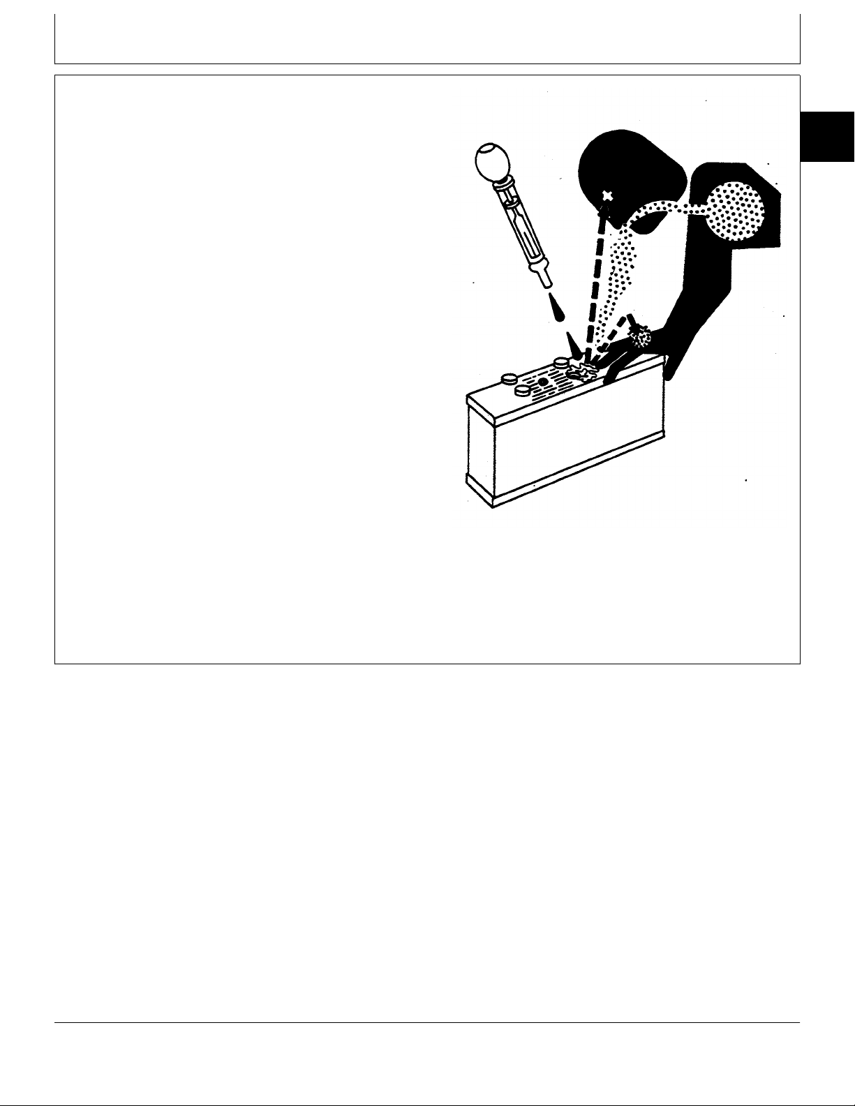
PREVENT BATTERY EXPLOSIONS
Keep sparks, lighted matches, and open flame away
from the top of battery. Battery gas can explode.
Never check battery charge by placing a metal object
across the posts. Use a volt-meter or hydrometer.
Do not charge a frozen battery; it may explode. Warm
battery to 16˚C (60˚F).
PREPARE FOR EMERGENCIES
Be prepared if a fire starts.
Keep a first aid kit and fire extinguisher handy.
Keep emergency numbers for doctors, ambulance
service, hospital, and fire department near your
telephone.
TS204 -UN-23AUG88
DX,SPARKS -19-03MAR93
DX,FIRE2 -19-03MAR93
TM1590 (17MAY95) 10-05-2 316, 318 & 420 Lawn and Garden Tractors
020895
TS291 -UN-23AUG88
Page 13
PREVENT ACID BURNS
Safety
Sulfuric acid in battery electrolyte is poisonous. It is
strong enough to burn skin, eat holes in clothing, and
cause blindness if splashed into eyes.
Avoid the hazard by:
1. Filling batteries in a well-ventilated area.
2. Wearing eye protection and rubber gloves.
3. Avoiding breathing fumes when electrolyte is added.
4. Avoiding spilling or dripping electrolyte.
5. Use proper jump start procedure.
If you spill acid on yourself:
1. Flush your skin with water.
2. Apply baking soda or lime to help neutralize the acid.
3. Flush your eyes with water for 15—30 minutes. Get
medical attention immediately.
If acid is swallowed:
1. Do not induce vomiting.
2. Drink large amounts of water or milk, but do not
exceed 2 L (2 quarts).
3. Get medical attention immediately.
10
05
3
TS203 -UN-23AUG88
DX,POISON -19-21APR93
TM1590 (17MAY95) 10-05-3 316, 318 & 420 Lawn and Garden Tractors
020895
Page 14
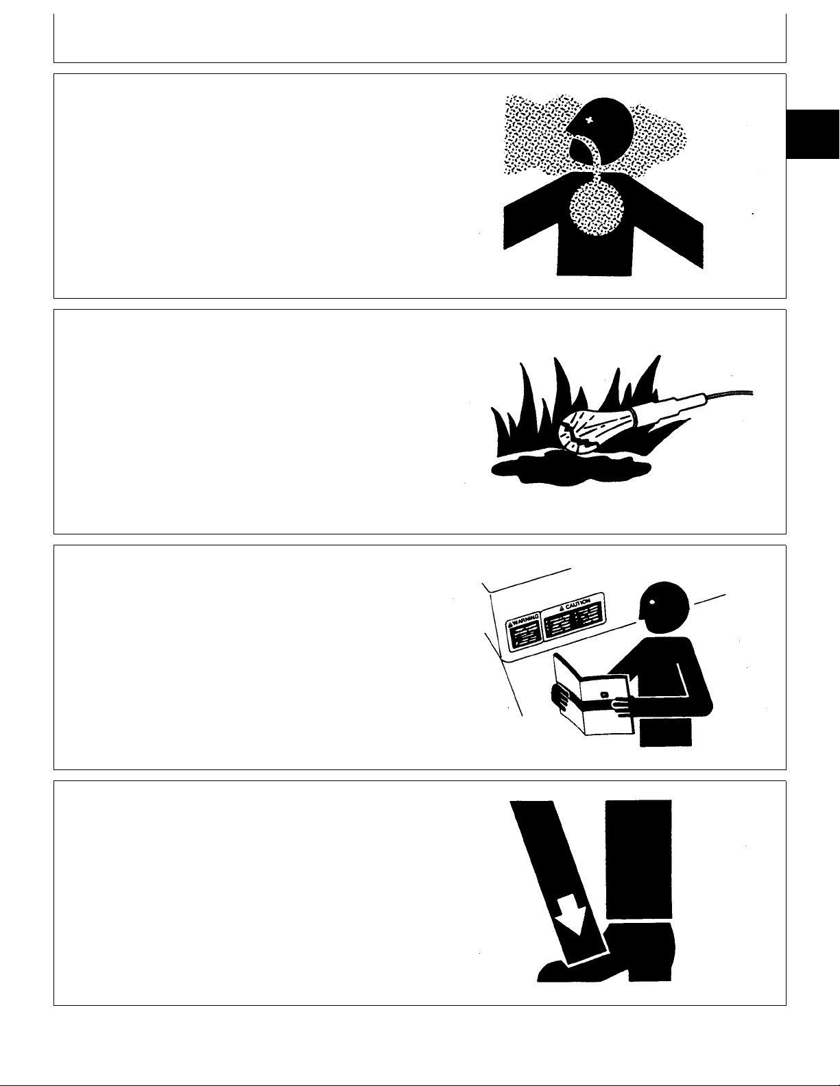
HANDLE CHEMICAL PRODUCTS SAFELY
10
Direct exposure to hazardous chemicals can cause
05
serious injury. Potentially hazardous chemicals used with
4
John Deere equipment include such items as lubricants,
coolants, paints, and adhesives.
A Material Safety Data Sheet (MSDS) provides specific
details on chemical products: physical and health
hazards, safety procedures, and emergency response
techniques.
Check the MSDS before you start any job using a
hazardous chemical. That way you will know exactly
what the risks are and how to do the job safely. Then
follow procedures and recommended equipment.
(See your John Deere dealer for MSDS’s on chemical
products used with John Deere equipment.)
Safety
TS1132 -UN-26NOV90
AVOID HIGH-PRESSURE FLUIDS
Escaping fluid under pressure can penetrate the skin
causing serious injury.
Avoid the hazard by relieving pressure before
disconnecting hydraulic or other lines. Tighten all
connections before applying pressure.
Search for leaks with a piece of cardboard. Protect
hands and body from high pressure fluids.
If an accident occurs, see a doctor immediately. Any
fluid injected into the skin must be surgically removed
within a few hours or gangrene may result. Doctors
unfamiliar with this type of injury should reference a
knowledgeable medical source. Such information is
available from Deere & Company Medical Department in
Moline, Illinois, U.S.A.
DX,MSDS,NA -19-03MAR93
X9811 -UN-23AUG88
DX,FLUID -19-03MAR93
TM1590 (17MAY95) 10-05-4 316, 318 & 420 Lawn and Garden Tractors
020895
Page 15
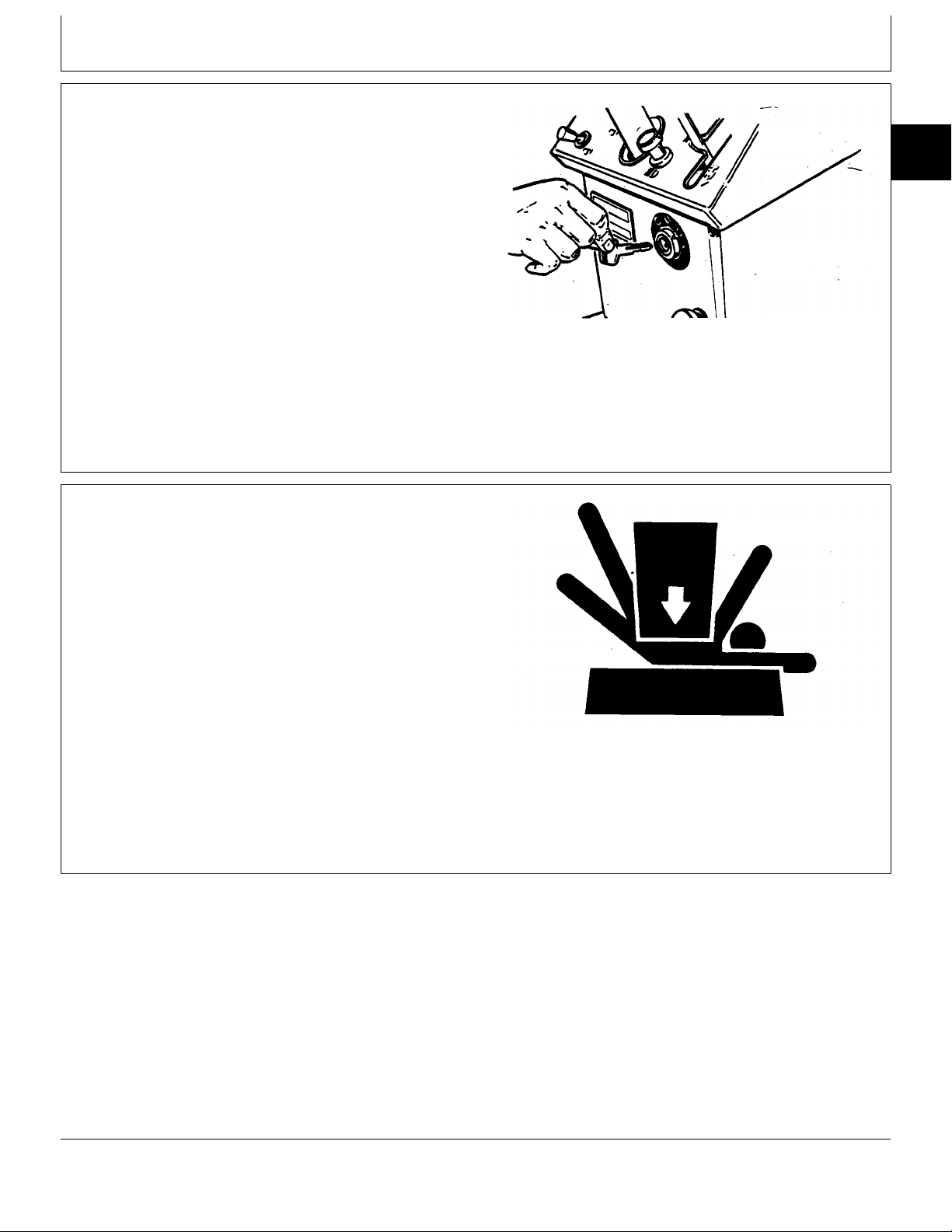
PREPARE MACHINE FOR REPAIR
Safety
1. Move hydrostatic control lever to STOP position.
2. Disengage PTO’s
3. Lower all equipment to the ground.
4. Engage park brake.
5. Stop the engine and remove the key.
6. Operate all hydraulic control levers to release
hydraulic pressure in the system.
Before you leave the operator’s seat, wait for engine and
attachment parts to stop moving.
SUPPORT MACHINE PROPERLY
Always lower the attachment or implement to the ground
before you work on the machine. If you must work on a
lifted machine or attachment, securely support the
machine or attachment.
10
05
5
M34228 -UN-24APR89
MX,1005R,8 -19-01APR86
Do not support the machine on cinder blocks, hollow
tiles, or props that may crumble under continuous load.
Do not work under a machine that is supported solely by
a jack. Follow recommended procedures in this manual.
TS229 -UN-23AUG88
DX,LOWER -19-04JUN90
TM1590 (17MAY95) 10-05-5 316, 318 & 420 Lawn and Garden Tractors
020895
Page 16
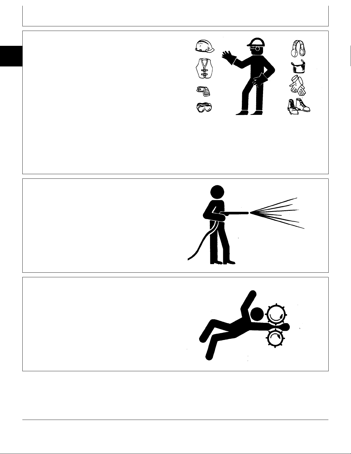
WEAR PROTECTIVE CLOTHING
10
Wear close fitting clothing and safety equipment
05
appropriate to the job.
6
Prolonged exposure to loud noise can cause impairment
or loss of hearing.
Wear a suitable hearing protective device such as
earmuffs or earplugs to protect against objectionable or
uncomfortable loud noises.
Operating equipment safely requires the full attention of
the operator. Do not wear radio or music headphones
while operating machine.
Safety
TS206 -UN-23AUG88
DX,WEAR -19-10SEP90
WORK IN CLEAN AREA
Before starting a job:
• Clean work area and machine.
• Make sure you have all necessary tools to do your job.
• Have the right parts on hand.
• Read all instructions thoroughly; do not attempt
shortcuts.
SERVICE MACHINES SAFELY
Tie long hair behind your head. Do not wear a necktie,
scarf, loose clothing, or necklace when you work near
machine tools or moving parts. If these items were to get
caught, severe injury could result.
Remove rings and other jewelry to prevent electrical
shorts and entanglement in moving parts.
T6642EJ -UN-18OCT88
DX,CLEAN -19-04JUN90
DX,LOOSE -19-04JUN90
TM1590 (17MAY95) 10-05-6 316, 318 & 420 Lawn and Garden Tractors
020895
TS228 -UN-23AUG88
Page 17
WORK IN VENTILATED AREA
Safety
Engine exhaust fumes can cause sickness or death. If it
is necessary to run an engine in an enclosed area,
remove the exhaust fumes from the area with an
exhaust pipe extension.
If you do not have an exhaust pipe extension, open the
doors and get outside air into the area.
ILLUMINATE WORK AREA SAFELY
Illuminate your work area adequately but safely. Use a
portable safety light for working inside or under the
machine. Make sure the bulb is enclosed by a wire
cage. The hot filament of an accidentally broken bulb
can ignite spilled fuel or oil.
10
05
7
TS220 -UN-23AUG88
DX,AIR -19-04JUN90
TS223 -UN-23AUG88
DX,LIGHT -19-04JUN90
REPLACE SAFETY SIGNS
Replace missing or damaged safety signs. See the
machine operator’s manual for correct safety sign
placement.
USE PROPER LIFTING EQUIPMENT
Lifting heavy components incorrectly can cause severe
injury or machine damage.
Follow recommended procedure for removal and
installation of components in the manual.
TS201 -UN-23AUG88
DX,SIGNS1 -19-04JUN90
DX,LIFT -19-04JUN90
TM1590 (17MAY95) 10-05-7 316, 318 & 420 Lawn and Garden Tractors
020895
TS226 -UN-23AUG88
Page 18
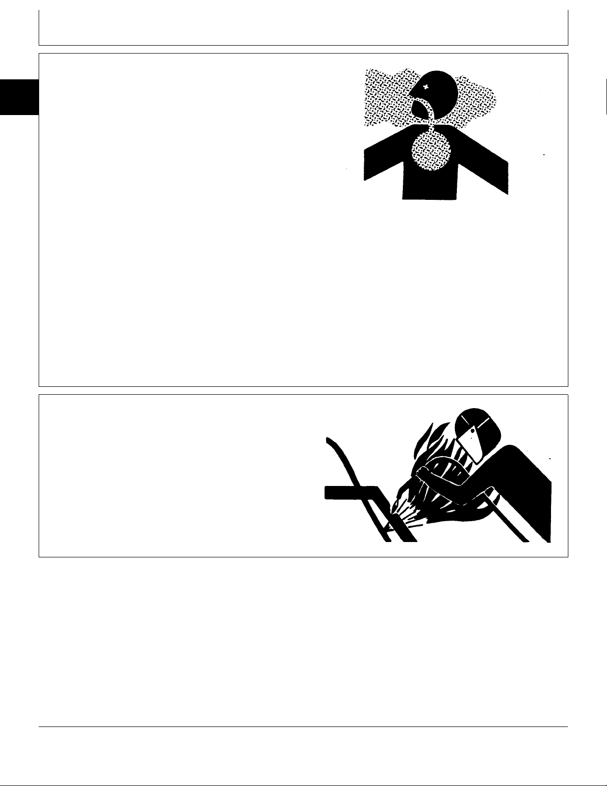
REMOVE PAINT BEFORE WELDING OR HEATING
10
05
Avoid potentially toxic fumes and dust.
8
Hazardous fumes can be generated when paint is
heated by welding, soldering, or using a torch.
Do all work outside or in a well ventilated area. Dispose
of paint and solvent properly.
Safety
Remove paint before welding or heating:
• If you sand or grind paint, avoid breathing the dust.
Wear an approved respirator.
• If you use solvent or paint stripper, remove stripper
with soap and water before welding. Remove solvent or
paint stripper containers and other flammable material
from area. Allow fumes to disperse at least 15 minutes
before welding or heating.
AVOID HEATING NEAR PRESSURIZED FLUID LINES
Flammable spray can be generated by heating near
pressurized fluid lines, resulting in severe burns to
yourself and bystanders. Do not heat by welding,
soldering, or using a torch near pressurized fluid lines or
other flammable materials. Pressurized lines can be
accidentally cut when heat goes beyond the immediate
flame area.
TS220 -UN-23AUG88
DX,PAINT -19-03MAR93
DX,TORCH -19-03MAR93
TM1590 (17MAY95) 10-05-8 316, 318 & 420 Lawn and Garden Tractors
020895
TS953 -UN-15MAY90
Page 19
SERVICE TIRES SAFELY
Safety
Explosive separation of a tire and rim parts can cause
serious injury or death.
Do not attempt to mount a tire unless you have the
proper equipment and experience to perform the job.
Always maintain the correct tire pressure. Do not inflate
the tires above the recommended pressure. Never weld
or heat a wheel and tire assembly. The heat can cause
an increase in air pressure resulting in a tire explosion.
Welding can structurally weaken or deform the wheel.
When inflating tires, use a clip-on chuck and extension
hose long enough to allow you to stand to one side and
NOT in front of or over the tire assembly. Use a safety
cage if available.
Check wheels for low pressure, cuts, bubbles, damaged
rims or missing lug bolts and nuts.
10
05
9
TS952 -UN-12APR90
AVOID HARMFUL ASBESTOS DUST
Avoid breathing dust that may be generated when
handling components containing asbestos fibers. Inhaled
asbestos fibers may cause lung cancer.
Components in products that may contain asbestos fibers
are brake pads, brake band and lining assemblies, clutch
plates, and some gaskets. The asbestos used in these
components is usually found in a resin or sealed in
some way. Normal handling is not hazardous as long as
airborne dust containing asbestos is not generated.
Avoid creating dust. Never use compressed air for
cleaning. Avoid brushing or grinding material containing
asbestos. When servicing, wear an approved respirator.
A special vacuum cleaner is recommended to clean
asbestos. If not available, apply a mist of oil or water on
the material containing asbestos.
Keep bystanders away from the area.
DX,TIRECP -19-24AUG90
TS220 -UN-23AUG88
DX,DUST -19-15MAR91
TM1590 (17MAY95) 10-05-9 316, 318 & 420 Lawn and Garden Tractors
020895
Page 20
PRACTICE SAFE MAINTENANCE
10
Understand service procedure before doing work. Keep
05
area clean and dry.
10
Never lubricate, service, or adjust machine while it is
moving. Keep hands, feet , and clothing from
power-driven parts. Disengage all power and operate
controls to relieve pressure. Lower equipment to the
ground. Stop the engine. Remove the key. Allow
machine to cool.
Securely support any machine elements that must be
raised for service work.
Keep all parts in good condition and properly installed.
Fix damage immediately. Replace worn or broken parts.
Remove any buildup of grease, oil, or debris.
Disconnect battery ground cable (-) before making
adjustments on electrical systems or welding on
machine.
Safety
USE PROPER TOOLS
Use tools appropriate to the work. Makeshift tools and
procedures can create safety hazards.
Use power tools only to loosen threaded parts and
fasteners.
For loosening and tightening hardware, use the correct
size tools. DO NOT use U.S. measurement tools on
metric fasteners. Avoid bodily injury caused by slipping
wrenches.
Use only service parts meeting John Deere
specifications.
TS218 -UN-23AUG88
DX,SERV -19-03MAR93
TS779 -UN-08NOV89
DX,REPAIR -19-04JUN90
TM1590 (17MAY95) 10-05-10 316, 318 & 420 Lawn and Garden Tractors
020895
Page 21
DISPOSE OF WASTE PROPERLY
Safety
Improperly disposing of waste can threaten the
environment and ecology. Potentially harmful waste used
with John Deere equipment include such items as oil,
fuel, coolant, brake fluid, filters, and batteries.
Use leakproof containers when draining fluids. Do not
use food or beverage containers that may mislead
someone into drinking from them.
Do not pour waste onto the ground, down a drain, or
into any water source.
Air conditioning refrigerants escaping into the air can
damage the Earth’s atmosphere. Government regulations
may require a certified air conditioning service center to
recover and recycle used air conditioning refrigerants.
Inquire on the proper way to recycle or dispose of waste
from your local environmental or recycling center, or from
your John Deere dealer.
10
05
11
TS1133 -UN-26NOV90
LIVE WITH SAFETY
Before returning machine to customer, make sure
machine is functioning properly, especially the safety
systems. Install all guards and shields.
DX,DRAIN -19-03MAR93
TS231 -19-07OCT88
DX,LIVE -19-25SEP92
TM1590 (17MAY95) 10-05-11 316, 318 & 420 Lawn and Garden Tractors
020895
Page 22

10
05
12
Safety
TM1590 (17MAY95) 10-05-12 316, 318 & 420 Lawn and Garden Tractors
020895
Page 23

MACHINE SPECIFICATIONS
Group 10
General Specifications
316 318 420
ENGINE
Manufacturer . . . . . . . . . . . . . . . . Onan . . . . . . . . . . . . Onan . . . . . . . . . . . . Onan
Type . . . . . . . . . . . . . . . . . . . . . Gasoline . . . . . . . . . . Gasoline . . . . . . . . . . Gasoline
Model Number
Early . . . . . . . . . . . . . . . . . . . . B43E . . . . . . . . . . . . B43G . . . . . . . . . . . . B48G
Later . . . . . . . . . . . . . . . . . . . . P218G . . . . . . . . . . . P218G . . . . . . . . . . . P220G
Horsepower (SAEJ607)
Early . . . . . . . . . . . . . . . . . . . . 11.9 kW (16 hp) . . . . . 13.4 kW (18 hp) . . . . . 14.9 kW (20 hp)
Later . . . . . . . . . . . . . . . . . . . . 13.4 kW (18 hp) . . . . . 13.4 kW (18 hp) . . . . . 14.9 kW (20 hp)
Torque . . . . . . . . . . . . . . . . . . . . 4.4 kg m (31.5 ft lbs) . . 4.4 kg m (31.5 ft lbs) . . 4.4 kg m (31.8 ft lbs)
Engine Rated Speeds
Fast Idle (No Load) . . . . . . . . . . 3450 rpm . . . . . . . . . . 3450 rpm . . . . . . . . . . 3450 rpm
Low Idle (No Load) . . . . . . . . . . 1350 rpm . . . . . . . . . . 1350 rpm . . . . . . . . . . 1350 rpm
Number of Cylinders . . . . . . . . . . . 2 . . . . . . . . . . . . . . . 2 . . . . . . . . . . . . . . . 2
Crankshaft Alignment . . . . . . . . . . Horizontal . . . . . . . . . Horizontal . . . . . . . . . Horizontal
Stroke/Cycle . . . . . . . . . . . . . . . . 4 Cycle . . . . . . . . . . . 4 Cycle . . . . . . . . . . . 4 Cycle
Bore . . . . . . . . . . . . . . . . . . . . . 82.55 mm (3.25 in.) . . . 82.55 mm (3.25 in.) . . . 82.55 mm (3.25 in.)
Stroke
Early . . . . . . . . . . . . . . . . . . . . 66 mm (2.620 in.) . . . . 66 mm (2.620 in.) . . . . 73 mm (2.875 in.)
Later . . . . . . . . . . . . . . . . . . . . 73 mm (2.875 in.) . . . . 73 mm (2.875 in.) . . . . 73 mm (2.875 in.)
Displacement
Early . . . . . . . . . . . . . . . . . . . . 710 cm3 (43.3 cu in.) 710 cm3 (43.3 cu in.) 782 cm3 (47.7 cu in.)
Later . . . . . . . . . . . . . . . . . . . . 782 cm3 (47.7 cu in.) 782 cm3 (47.7 cu in.) 782 cm3 (47.7 cu in.)
Compression Ratio
Early . . . . . . . . . . . . . . . . . . . . 6.2:1 . . . . . . . . . . . . . 6.5:1 . . . . . . . . . . . . . 7.0:1
Later . . . . . . . . . . . . . . . . . . . . 7.0:1 . . . . . . . . . . . . . 7.0:1 . . . . . . . . . . . . . 7.0:1
Cylinder Material . . . . . . . . . . . . . Aluminum . . . . . . . . . Aluminum . . . . . . . . . Aluminum
Cooling . . . . . . . . . . . . . . . . . . . Air . . . . . . . . . . . . . . Air . . . . . . . . . . . . . . Air
Air Filter Type . . . . . . . . . . . . . . . Dry with Pre-Cleaner . . Dry with Pre-Cleaner . . Dry with Pre-Cleaner
Lubrication System . . . . . . . . . . . . Full Pressure w/Filter Full Pressure w/Filter Full Pressure w/Filter
Crankcase Capacity (w/o Filter) . . . 1.4 L (1.5 U.S. qt) . . . . 1.4 L (1.5 U.S. qt) . . . . 1.4 L (1.5 U.S. qt)
Oil Filter . . . . . . . . . . . . . . . . . . . Replaceable . . . . . . . . Replaceable . . . . . . . . Replaceable
Spark Plugs . . . . . . . . . . . . . . . . NGK BPR5EFS . . . . . NGK BPR5EFS . . . . . NGK BPR5EFS
Champion RS14YC . . . Champion RS14YC . . . Champion RS14YC
FUEL SYSTEM
Fuel Tank Location . . . . . . . . . . . . Rear . . . . . . . . . . . . . Rear . . . . . . . . . . . . . Rear
Fuel Gauge . . . . . . . . . . . . . . . . . Standard . . . . . . . . . . Standard . . . . . . . . . . Standard
Fuel Reserve System . . . . . . . . . . N/A . . . . . . . . . . . . . . Standard . . . . . . . . . . Standard
Fuel Tank Capacity . . . . . . . . . . . 17 L (4.5 U.S. gal) . . . 17 L (4.5 U.S. gal) . . . 25 L (6.5 U.S. gal)
Fuel (min. octane) . . . . . . . . . . . . 85 Octane Unleaded . . 85 Octane Unleaded . . 85 Octane Unleaded
Fuel Pump Location . . . . . . . . . . . Engine . . . . . . . . . . . Engine . . . . . . . . . . . Engine
Fuel Pump Type . . . . . . . . . . . . . Pulse . . . . . . . . . . . . Pulse . . . . . . . . . . . . Pulse
Fuel Delivery . . . . . . . . . . . . . . . . Fixed Jet Carburetor . . Fixed Jet Carburetor . . Fixed Jet Carburetor
10
10
1
ELECTRICAL SYSTEM
Ignition . . . . . . . . . . . . . . . . . . . . Electronic . . . . . . . . . . Electronic . . . . . . . . . . Electronic
Type of Starter . . . . . . . . . . . . . . 12 Volts, Solenoid . . . . 12 Volts, Solenoid . . . . 12 Volts, Solenoid
Charging System . . . . . . . . . . . . . Early, 15 amp Stator . . 20 amp Stator . . . . . . 20 amp Stator
Later, 20 amp Stator
Continued on next page.
TM1590 (17MAY95) 10-10-1 316, 318 & 420 Lawn and Garden Tractors
MX,15901010,1 -19-25APR95
020895
Page 24

General Specifications/Machine Specifications
316 318 420
ELECTRICAL SYSTEM, continued
10
Battery Type . . . . . . . . . . . . . . . . BCI Group 22F . . . . . . BCI Group 22F . . . . . . BCI Group 22F
10
Battery Voltage . . . . . . . . . . . . . . . 12V . . . . . . . . . . . . . . 12V . . . . . . . . . . . . . . 12V
2
Battery Reserve Capacity @
25 amp . . . . . . . . . . . . . . . . . . 102 minutes . . . . . . . . 102 minutes . . . . . . . . 102 minutes
Battery Cold Cranking amp @ 0˚F . . 491 amp . . . . . . . . . . 491 amp . . . . . . . . . . 491 amp
Headlights . . . . . . . . . . . . . . . . . . Standard . . . . . . . . . . Standard . . . . . . . . . . Standard
Rear Reflector/Tail Lights . . . . . . . . Standard . . . . . . . . . . Standard . . . . . . . . . . Standard
Dash Indicator Lights . . . . . . . . . Standard . . . . . . . . . . Standard . . . . . . . . . . Standard
Operator Presence System . . . . . . . Standard . . . . . . . . . . Standard . . . . . . . . . . Standard
Dash Instrumentation
Hourmeter . . . . . . . . . . . . . . . . Standard . . . . . . . . . . Standard . . . . . . . . . . Standard
POWER TRAIN
Transmission Type . . . . . . . . . . . . Hydrostatic . . . . . . . . . Hydrostatic . . . . . . . . . Hydrostatic, 2 Ranges
Number of Speeds . . . . . . . . . . . . Infinite . . . . . . . . . . . . Infinite . . . . . . . . . . . . Infinite
Travel Speeds
Forward . . . . . . . . . . . . . . . . . . 0—12.38 km/h . . . . . . . 0—12.38 km/h . . . . . . . N/A
(0—7.69 mph) . . . . . . . (0—7.69 mph) . . . . . . . N/A
Reverse . . . . . . . . . . . . . . . . . . 0—6.19 km/h . . . . . . . 0—6.19 km/h . . . . . . . N/A
(0—3.85 mph) . . . . . . . (0—3.85 mph) . . . . . . . N/A
Forward, High . . . . . . . . . . . . . . N/A . . . . . . . . . . . . . . N/A . . . . . . . . . . . . . . 0—15.04 km/h
(0—9.35 mph)
Forward, Low . . . . . . . . . . . . . . N/A . . . . . . . . . . . . . . N/A . . . . . . . . . . . . . . 0—9.35 km/h
(0—5.80 mph)
Reverse, High . . . . . . . . . . . . . . N/A . . . . . . . . . . . . . . N/A . . . . . . . . . . . . . . 0—7.52 km/h
(0—4.67 mph)
Reverse, Low . . . . . . . . . . . . . . N/A . . . . . . . . . . . . . . N/A . . . . . . . . . . . . . . 0—4.66 km/h
(0—2.90 mph)
Transmission Capacity w/Filter . . . . 6.1 L (13 U.S. pt) . . . . 7.1 L (15 U.S. pt) . . . . 7.1 L (15 U.S. pt)
Transmission Oil Cooler . . . . . . . . . N/A . . . . . . . . . . . . . . Standard . . . . . . . . . . Standard
Transmission Oil Filter . . . . . . . . . . Standard . . . . . . . . . . Standard . . . . . . . . . . Standard
Differential Lock . . . . . . . . . . . . . . N/A . . . . . . . . . . . . . . N/A . . . . . . . . . . . . . . Standard
STEERING
Type . . . . . . . . . . . . . . . . . . . . . . Manual . . . . . . . . . . . . Power, Hydrostatic . . . . Power, Hydrostatic
BRAKES
Location . . . . . . . . . . . . . . . . . . . Rear Wheels . . . . . . . . Rear Wheels . . . . . . . . Rear Wheels
Individually Controlled . . . . . . . . . . N/A . . . . . . . . . . . . . . Standard . . . . . . . . . . Standard
Type . . . . . . . . . . . . . . . . . . . . . . Shoe and Drum . . . . . . Shoe and Drum . . . . . . Shoe and Drum
Return-to-Neutral Braking . . . . . . . . Standard . . . . . . . . . . Standard . . . . . . . . . . Standard
Parking . . . . . . . . . . . . . . . . . . . . Yes . . . . . . . . . . . . . . Yes . . . . . . . . . . . . . . Yes
HYRAULIC SYSTEM
Type . . . . . . . . . . . . . . . . . . . . . . Single-Function . . . . . . Two-Function Three-Function
(One w/Float) . . . . . . . . (One w/Float)
Hydraulic Couplers . . . . . . . . . . . . One Set . . . . . . . . . . . Two Sets . . . . . . . . . . Two Sets
Continued on next page.
MX,15901010,2 -19-25APR95
TM1590 (17MAY95) 10-10-2 316, 318 & 420 Lawn and Garden Tractors
020895
Page 25

General Specifications/Machine Specifications
316 318 420
PTO
Front . . . . . . . . . . . . . . . . . . . . . Standard . . . . . . . . . . Standard . . . . . . . . . . Standard
Rear . . . . . . . . . . . . . . . . . . . . . . Optional . . . . . . . . . . . Optional . . . . . . . . . . . Optional
Type . . . . . . . . . . . . . . . . . . . . . . Electric Clutch . . . . . . . Electric Clutch . . . . . . . Electric Clutch
Control . . . . . . . . . . . . . . . . . . . . Elec. Switch on Dash . . Elec. Switch on Dash . . Elec. Switch on Dash
PTO rpm (No Load)
Front . . . . . . . . . . . . . . . . . . . . 3450 . . . . . . . . . . . . . 3450 . . . . . . . . . . . . . 3450
Rear . . . . . . . . . . . . . . . . . . . . 2000 . . . . . . . . . . . . . 2000 . . . . . . . . . . . . . 2000
MOWER ATTACHMENT
Compatibility . . . . . . . . . . . . . . . . 38, 46 and 50 Inch . . . 38, 46 and 50 Inch . . . 50 and 60 Inch
260 Rotary . . . . . . . . . 260 Rotary
Lift System . . . . . . . . . . . . . . . . . Hydraulic . . . . . . . . . . Hydraulic . . . . . . . . . . Hydraulic
WHEEL TREAD
Front . . . . . . . . . . . . . . . . . . . . . 813 mm (32 in.) . . . . . . 813 mm (32 in.) . . . . . . 914 mm (36 in.)
Rear
Narrow . . . . . . . . . . . . . . . . . . . 775 mm (30.5 in.) . . . . 775 mm (30.5 in.) . . . . 818 mm (32 in.)
Wide . . . . . . . . . . . . . . . . . . . . 834 mm (32.8 in.) . . . . 834 mm (32.8 in.) . . . . 980 mm (38.6 in.)
TIRES
Standard Tires
Front Turf . . . . . . . . . . . . . . . . . 16 x 6.50-8, 2 PR . . . . 16 x 6.50-8, 2 PR . . . . 18 x 8.50-8, 4 PR
Rear Turf or Bar . . . . . . . . . . . . 23 x 10.50-12, 2 PR . . . 23 x 10.50-12, 2 PR . . . 26 x 12.00-12, 2 PR
Optional Tires
Front (Turf) . . . . . . . . . . . . . . . . 16 x 6.50-8, 4 PR . . . . 16 x 6.50-8, 4 PR . . . . N/A
Rear (Turf or Bar) . . . . . . . . . . . 23 x 8.50-12, 2 PR . . . 23 x 8.50-12, 2 PR . . . N/A
Inflation Pressure
Front . . . . . . . . . . . . . . . . . . . . 41—110 kPa (6—16 psi) 41—110 kPa (6—16 psi) 41—152 kPa (6—22 psi)
Rear . . . . . . . . . . . . . . . . . . . . 34—69 kPa (5—10 psi) 34—69 kPa (5—10 psi) 34—69 kPa (5—10 psi)
10
10
3
SEAT
Style . . . . . . . . . . . . . . . . . . . . . . High-Back . . . . . . . . . . High-Back . . . . . . . . . . High-Back
Suspension . . . . . . . . . . . . . . . . . 2 Spring . . . . . . . . . . . 2 Spring . . . . . . . . . . . 2 Spring
Adjustment . . . . . . . . . . . . . . . . . Slide Rail . . . . . . . . . . Slide Rail . . . . . . . . . . Slide Rail
DIMENSIONS
Wheel Base . . . . . . . . . . . . . . . . . 1.2 m (46 in.) . . . . . . . 1.2 m (46 in.) . . . . . . . 1.3 m (52 in.)
Overall Length . . . . . . . . . . . . . . . 1.8 m (69.5 in.) . . . . . . 1.8 m (69.5 in.) . . . . . . 2.0 m (77 in.)
Overall Height . . . . . . . . . . . . . . . 1.1 m (44.5 in.) . . . . . . 1.1 m (44.5 in.) . . . . . . 1.21 m (47.5 in.)
Overall Width (max.) . . . . . . . . . . . 1.1 m (43.3 in.) . . . . . . 1.1 m (43.3 in.) . . . . . . 1.31 m (51.5 in.)
Overall Width (min.) . . . . . . . . . . . 1.04 m (41 in.) . . . . . . 1.04 m (41 in.) . . . . . . 1.14 m (45 in.)
Turning Radius
Inside Rear Wheel . . . . . . . . . . . 660 mm (26 in.) . . . . . . 660 mm (26 in.) . . . . . . 660 mm (26 in.)
Outside Front Wheel . . . . . . . . . 2.0 m (80 in.) . . . . . . . 2.0 m (80 in.) . . . . . . . 2.2 m (86 in.)
NET WEIGHT (No Fuel) . . . . . . . . 354 kg (780 lbs) . . . . . 354 kg (780 lbs) . . . . . 408 kg (913 lbs)
SHIPPING WEIGHT . . . . . . . . . . . 386 kg (852 lbs) . . . . . 386 kg (852 lbs) . . . . . 450 kg (993 lbs)
(Specifications and design subject to change without notice.)
MX,15901010,3 -19-25APR95
TM1590 (17MAY95) 10-10-3 316, 318 & 420 Lawn and Garden Tractors
020895
Page 26

10
10
4
General Specifications/Machine Specifications
TM1590 (17MAY95) 10-10-4 316, 318 & 420 Lawn and Garden Tractors
020895
Page 27

REPAIR SPECIFICATIONS
Group 15
Repair Specifications
Item Specifications
ENGINE
For all repair specifications—Use CTM2
Engine Mounting Cap Screw/Nut Torque
316 . . . . . . . . . . . . . . . . . . . . . . . . . . . . . . . . . . . . . . . . . . . . . . . . . . . . . . . . . . . . 39 N·m (29 lb-ft)
318 and 420 . . . . . . . . . . . . . . . . . . . . . . . . . . . . . . . . . . . . . . . . . . . . . . . . . . . . . . 47 N·m (34 lb-ft)
Drive Shaft-to-Engine Cap Screw Torque . . . . . . . . . . . . . . . . . . . . . . . . . . . . . . . . . . . . 27 N·m (20 lb-ft)
PTO Belt Tension Spring Length (420)
Horizontal Adjuster (Early) . . . . . . . . . . . . . . . . . . . . . . . . . . . . . . . . . . . . . . . . . . . . 41 mm (1.600 in.)
Vertical Adjuster (Later) . . . . . . . . . . . . . . . . . . . . . . . . . . . . . . . . . . . . . . . . . . . . . 35 mm (1.380 in.)
ELECTRICAL
Front PTO Clutch-to-Crankshaft Cap Screw Torque . . . . . . . . . . . . . . . . . . . . . . . . . . . . . 47 N·m (35 lb-ft)
PTO Clutch Armature-to-Rotor Clearance . . . . . . . . . . . . . . . . . . . . . . . . . . . . . . . . . 0.46 mm (0.018 in.)
PTO Belt Tension Spring Length (420)
Horizontal Adjuster (Early) . . . . . . . . . . . . . . . . . . . . . . . . . . . . . . . . . . . . . . . . . . . . 41 mm (1.600 in.)
Vertical Adjuster (Later) . . . . . . . . . . . . . . . . . . . . . . . . . . . . . . . . . . . . . . . . . . . . . 35 mm (1.380 in.)
POWER TRAIN
Transmission
Charge Pump-to-Transmission Cap Screw Torque . . . . . . . . . . . . . . . . . . . . . . . . . . . . . 70 N·m (52 lb-ft)
Transmission Cover Bearing Installation Height . . . . . . . . . . . . . . . 3 mm (0.118 in.) above housing surface
Center Section-to-Housing Cap Screw Torque . . . . . . . . . . . . . . . . . . . . . . . . . . . . . . . 35 N·m (26 lb-ft)
Transmission-to-Differential Cap Screw Torque . . . . . . . . . . . . . . . . . . . . . . . . . . . . . . . 45 N·m (33 lb-ft)
Axle Housing-to-Frame Cap Screw Torque . . . . . . . . . . . . . . . . . . . . . . . . . . . . . . . . . 100 N·m (75 lb-ft)
Brake Rod Spring Length . . . . . . . . . . . . . . . . . . . . . . . . . . . . . . . . . . . . . . . . . . . . 42 mm (1.650 in.)
Differential-to-Frame Support Cap Screw Torque . . . . . . . . . . . . . . . . . . . . . . . . . . . . . . 61 N·m (45 lb-ft)
Swashplate Control Arm-to-Control Shaft Nut Torque . . . . . . . . . . . . . . . . . . . . . . . . . . . 60 N·m (44 lb-ft)
Drive Shaft Clamping Yoke-to-Transmission Pump Shaft Cap Screw Torque . . . . . . . . . . . 60 N·m (44 lb-ft)
Differential
Case and Cover Oil Groove Depth (Minimum) . . . . . . . . . . . . . . . . . . . . . . . . . . . . 0.25 mm (0.010 in.)
Carrier Cap Screw Torque . . . . . . . . . . . . . . . . . . . . . . . . . . . . . . . . . . . . . . . . . . . . . 53 N·m (39 lb-ft)
Cover-to-Case Cap Screw Torque . . . . . . . . . . . . . . . . . . . . . . . . . . . . . . . . . . . . . 23 N·m (204 lb-in.)
Axle Housing
Differential Seal Depth . . . . . . . . . . . . . . . . . . . . . . . . . . . . . . . . . . . . . . . . . . . . . . 3 mm (0.118 in.)
Axle Housing-to-Differential Cap Screw Torque . . . . . . . . . . . . . . . . . . . . . . . . . . . . . . . 81 N·m (60 lb-ft)
Brake Plate-to-Axle Housing Cap Screw Torque . . . . . . . . . . . . . . . . . . . . . . . . . . . . . . 68 N·m (50 lb-ft)
Axle Housing-to-Frame Cap Screw Torque . . . . . . . . . . . . . . . . . . . . . . . . . . . . . . . . . 100 N·m (75 lb-ft)
Brake Rod Spring Length . . . . . . . . . . . . . . . . . . . . . . . . . . . . . . . . . . . . . . . . . . . . 42 mm (1.650 in.)
Brake Drum-to-Axle Nut Torque . . . . . . . . . . . . . . . . . . . . . . . . . . . . . . . . . . . . . . . . . 88 N·m (65 lb-ft)
Rear Wheel Cap Screw Torque . . . . . . . . . . . . . . . . . . . . . . . . . . . . . . . . . . . . . . . . . 70 N·m (52 lb-ft)
Drive Shaft
Drive Shaft-to-Engine Cap Screw Torque . . . . . . . . . . . . . . . . . . . . . . . . . . . . . . . . . . . 27 N·m (20 lb-ft)
Clamping Yoke-to-Transmission Pump Shaft Cap Screw Torque . . . . . . . . . . . . . . . . . . . 60 N·m (44 lb-ft)
10
15
1
Continued on next page.
TM1590 (17MAY95) 10-15-1 316, 318 & 420 Lawn and Garden Tractors
MX,15901015,1 -19-08MAY95
020895
Page 28

Repair Specifications/Repair Specifications
Item Specifications
10
STEERING AND BRAKES
15
Steering—316
2
Gearbox Mounting Cap Screw Torque . . . . . . . . . . . . . . . . . . . . . . . . . . . . . . . . . . . . . 95 N·m (70 lb-ft)
Steering Wheel-to-Shaft Nut Torque . . . . . . . . . . . . . . . . . . . . . . . . . . . . . . . . . . . . . 15 N·m (133 lb-in.)
Pitman Arm Nut Torque . . . . . . . . . . . . . . . . . . . . . . . . . . . . . . . . . . . . . . . . . . . . . 224 N·m (165 lb-ft)
Preload Adjuster Maximum End Clearance . . . . . . . . . . . . . . . . . . . . . . . . . . . . . . . . 0.05 mm (0.002 in.)
Side Cover-to-Gearbox Housing Cap Screw Torque . . . . . . . . . . . . . . . . . . . . . . . . . . . . 40 N·m (30 lb-ft)
Worm Bearing Preload Rolling Torque . . . . . . . . . . . . . . . . . . . . . . . . . . . . . . 0.60—1.0 N·m (5—8 lb-in.)
Over-Center Preload Rolling Torque . . . . . . . . . . . . . . . . . . . . . . . . . . . . . . 0.50—1.20 N·m (4—10 lb-in.)
Preload Adjuster Lock Nut Torque . . . . . . . . . . . . . . . . . . . . . . . . . . . . . . . . . . . . . . . 34 N·m (25 lb-ft)
Steering Shaft Universal Joint-to-Worm Shaft Cap Screw Torque . . . . . . . . . . . . . . . . . . 24 N·m (212 lb-in.)
Steering—318 and 420
Steering Wheel-to-Shaft Nut Torque . . . . . . . . . . . . . . . . . . . . . . . . . . . . . . . . . . . . . 15 N·m (133 lb-in.)
Rotor-to-Stator Maximum Allowable Clearance . . . . . . . . . . . . . . . . . . . . . . . . . . . . 0.08 mm (0.003 in.)
Steering Tube Bushing Depth . . . . . . . . . . . . . . . . . . . . . . . . . . . . 2.5 mm (0.100 in.) below top of tube
Commutator Cover-to-Commutator Screw Torque . . . . . . . . . . . . . . . . . . . . . . . . . . . . 1.4 N·m (12 lb-in.)
Port Cover Nut Torque . . . . . . . . . . . . . . . . . . . . . . . . . . . . . . . . . . . . . . . . . . . . . . . 30 N·m (22 lb-ft)
Check Ball Plug Torque (Early Version) . . . . . . . . . . . . . . . . . . . . . . . . . . . . . . . . . . 14 N·m (124 lb-in.)
Steering Cylinder Mounting Nut Torque . . . . . . . . . . . . . . . . . . . . . . . . . . . . . . . . . . 163 N·m (120 lb-ft)
Brakes
Brake Plate-to-Axle Housing Cap Screw Torque . . . . . . . . . . . . . . . . . . . . . . . . . . . . . . 68 N·m (50 lb-ft)
Axle Housing-to-Frame Cap Screw Torque . . . . . . . . . . . . . . . . . . . . . . . . . . . . . . . . . 100 N·m (75 lb-ft)
Brake Rod Spring Length . . . . . . . . . . . . . . . . . . . . . . . . . . . . . . . . . . . . . . . . . . . . 42 mm (1.650 in.)
Brake Drum-to-Axle Nut Torque . . . . . . . . . . . . . . . . . . . . . . . . . . . . . . . . . . . . . . . . . 88 N·m (65 lb-ft)
Rear Wheel Cap Screw Torque . . . . . . . . . . . . . . . . . . . . . . . . . . . . . . . . . . . . . . . . . 70 N·m (52 lb-ft)
HYDRAULICS
Single-Spool Valve
Spool Screw Torque . . . . . . . . . . . . . . . . . . . . . . . . . . . . . . . . . . . . . . . . . . . . . . . . . 4 N·m (35 lb-in.)
Spool Cap-to-Body Screw Torque . . . . . . . . . . . . . . . . . . . . . . . . . . . . . . . . . . . . . . . . 4 N·m (35 lb-in.)
Check Valve Plug Torque . . . . . . . . . . . . . . . . . . . . . . . . . . . . . . . . . . . . . . . . . . . . . 31 N·m (23 lb-ft)
Two-Spool Valve
Versions One, Two and Three
Spool Cap-to-Body Screw Torque . . . . . . . . . . . . . . . . . . . . . . . . . . . . . . . . . . . . . . 31 N·m (23 lb-ft)
Versions Four and Five
Spool Screw and Detent Torque . . . . . . . . . . . . . . . . . . . . . . . . . . . . . . . . . . . . . . . 4 N·m (35 lb-in.)
Spool Cap-to-Body Screw Torque . . . . . . . . . . . . . . . . . . . . . . . . . . . . . . . . . . . . . . 4 N·m (35 lb-in.)
Check Valve Plug Torque . . . . . . . . . . . . . . . . . . . . . . . . . . . . . . . . . . . . . . . . . . . . 31 N·m (23 lb-ft)
Three-Spool Valve
Versions One, Two and Three
Spool Cap-to-Body Screw Torque . . . . . . . . . . . . . . . . . . . . . . . . . . . . . . . . . . . . . . 31 N·m (23 lb-ft)
Lock Nut Torque (Version Three) . . . . . . . . . . . . . . . . . . . . . . . . . . . . . . . . . . . . . . . 31 N·m (23 lb-ft)
Version Four
Spool Screws and Detent Torque . . . . . . . . . . . . . . . . . . . . . . . . . . . . . . . . . . . . . . 4 N·m (35 lb-in.)
Spool Cap-to-Body Screw Torque . . . . . . . . . . . . . . . . . . . . . . . . . . . . . . . . . . . . . . 4 N·m (35 lb-in.)
Check Valve Plug Torque . . . . . . . . . . . . . . . . . . . . . . . . . . . . . . . . . . . . . . . . . . . . 31 N·m (23 lb-ft)
Continued on next page.
MX,15901015,2 -19-08MAY95
TM1590 (17MAY95) 10-15-2 316, 318 & 420 Lawn and Garden Tractors
020895
Page 29

Repair Specifications/Repair Specifications
Item Specifications
MISCELLANEOUS
Front Axle
PTO Belt Tension Spring Length (420)
Horizontal Adjuster (Early) . . . . . . . . . . . . . . . . . . . . . . . . . . . . . . . . . . . . . . . . . . 41 mm (1.600 in.)
Vertical Adjuster (Later) . . . . . . . . . . . . . . . . . . . . . . . . . . . . . . . . . . . . . . . . . . . 35 mm (1.380 in.)
Toe-In . . . . . . . . . . . . . . . . . . . . . . . . . . . . . . . . . . . . . . . . . . . . . . . . . . . . . . . . . 4.8 mm (3/16 in.)
Mower Blade Spindles
Driven Sheave-to-Spindle Lock Nut Torque . . . . . . . . . . . . . . . . . . . . . . . . . . . . . . . . 140 N·m (103 lb-ft)
Blade-to-Spindle Cap Screw Torque . . . . . . . . . . . . . . . . . . . . . . . . . . . . . . . . . . . . . . 73 N·m (54 lb-ft)
Mower Blade Jack Sheave
Jack Sheave-to-Spindle Lock Nut Torque . . . . . . . . . . . . . . . . . . . . . . . . . . . . . . . . . . 140 N·m (103 lb-ft)
Blade-to-Spindle Cap Screw Torque . . . . . . . . . . . . . . . . . . . . . . . . . . . . . . . . . . . . . . 73 N·m (54 lb-ft)
50-Inch Mower Gear Case
Plug Installation Depth . . . . . . . . . . . . . . . . . . . . . . . . . . . . 1.59 mm (0.062 in.) below gear case surface
Retainer Seal Installation Depth . . . . . . . . . . . . . . . . . . . . . . . . 2.54 mm (0.100 in.) below retainer surface
Retainer-to-Gear Case Cap Screw Torque . . . . . . . . . . . . . . . . . . . . . . . . . . . . . . . . . . 30 N·m (22 lb-ft)
Pillow Block Seal Installation Depth . . . . . . . . . . . . . . . . . . . . . . . 2.54 mm (0.100 in.) below block surface
Pillow Block-to-Gear Case Cap Screw Torque . . . . . . . . . . . . . . . . . . . . . . . . . . . . . . . 30 N·m (22 lb-ft)
Early 60-Inch Mower Gear Case
Cap-to-Gear Case Cap Screw Torque . . . . . . . . . . . . . . . . . . . . . . . . . . . . . . . . . . . . . 30 N·m (22 lb-ft)
Output Shaft Endplay . . . . . . . . . . . . . . . . . . . . . . . . . . . . . . . . . . . 0.025—0.076 mm (0.001—0.003 in.)
Input Shaft Backlash . . . . . . . . . . . . . . . . . . . . . . . . . . . . . . . . . . . 0.076—0.130 mm (0.003—0.005 in.)
Later 60-Inch Mower Gear Case
Gear Case Seal Installation Depth . . . . . . . . . . . . . . . . . . . . 2.54 mm (0.100 in.) below gear case surface
Retainer-to-Gear Case Cap Screw Torque . . . . . . . . . . . . . . . . . . . . . . . . . . . . . . . . . . 30 N·m (22 lb-ft)
Pillow Block Seal Installation Depth . . . . . . . . . . . . . . . . . . . . . . . 2.54 mm (0.100 in.) below block surface
Pillow Block-to-Gear Case Cap Screw Torque . . . . . . . . . . . . . . . . . . . . . . . . . . . . . . . 30 N·m (22 lb-ft)
260 Rotary Mower Gear Case
End Cap-to-Gear Case Cap Screw Torque . . . . . . . . . . . . . . . . . . . . . . . . . . . . . . . . . . 30 N·m (22 lb-ft)
Input Shaft Endplay . . . . . . . . . . . . . . . . . . . . . . . . . . . . . . . . . . . . 0.025—0.076 mm (0.001—0.003 in.)
Output Shaft Backlash . . . . . . . . . . . . . . . . . . . . . . . . . . . . . . . . . . 0.076—0.130 mm (0.003—0.005 in.)
Housing-to-Gear Case Cap Screw Torque . . . . . . . . . . . . . . . . . . . . . . . . . . . . . . . . . . 30 N·m (22 lb-ft)
MX,15901015,6 -19-20MAR95
10
15
3
TM1590 (17MAY95) 10-15-3 316, 318 & 420 Lawn and Garden Tractors
020895
Page 30
Repair Specifications/Metric Series Torque Chart
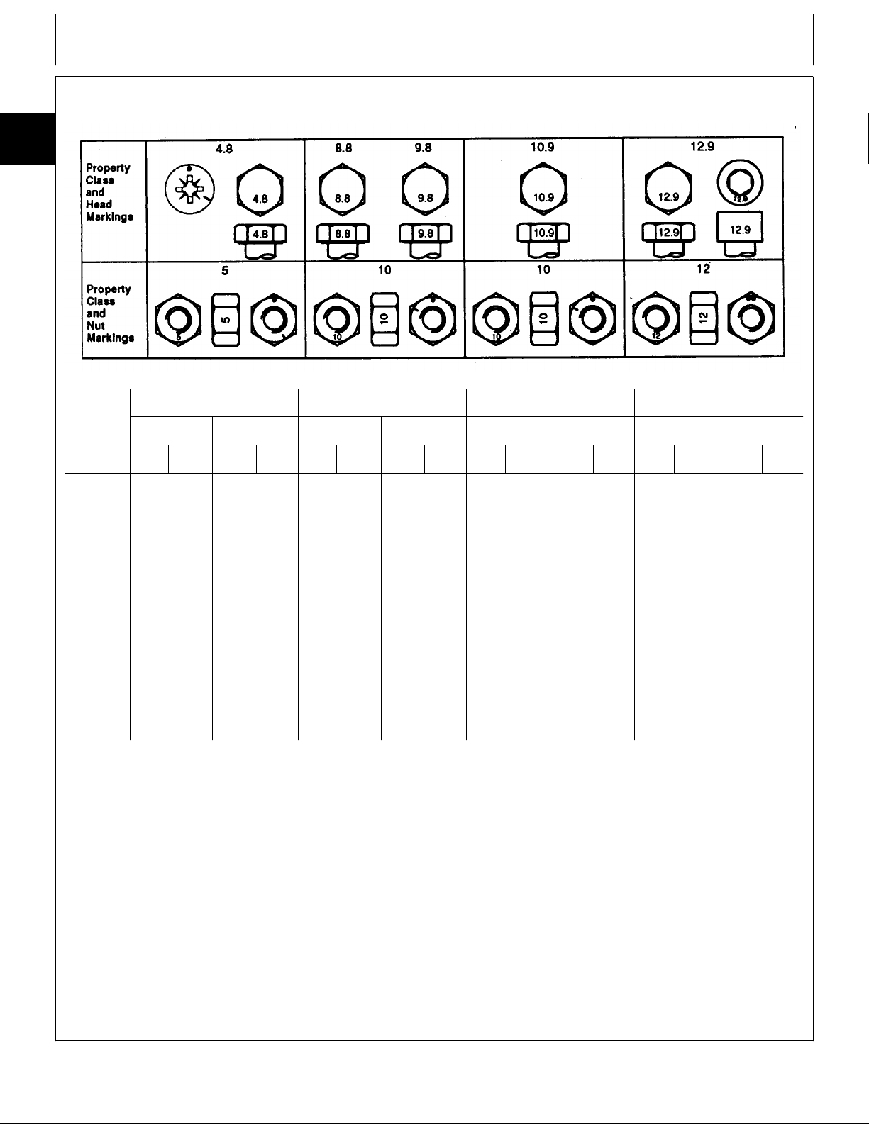
METRIC BOLT AND CAP SCREW TORQUE VALUES
10
15
4
Class 4.8 Class 8.8 or 9.8 Class 10.9 Class 12.9
TS1163 -19-04MAR91
Size Lubricated
N·m lb-ft N·m lb-ft N·m lb-ft N·m lb-ft N·m lb-ft N·m lb-ft N·m lb-ft N·m lb-ft
M6 4.8 3.5 6 4.5 9 6.5 11 8.5 13 9.5 17 12 15 11.5 19 14.5
M8 12 8.5 15 11 22 16 28 20 32 24 40 30 37 28 47 35
M10 23 17 29 21 43 32 55 40 63 47 80 60 75 55 95 70
M12 40 29 50 37 75 55 95 70 110 80 140 105 130 95 165 120
M14 63 47 80 60 120 88 150 110 175 130 225 165 205 150 260 190
M16 100 73 125 92 190 140 240 175 275 200 350 255 320 240 400 300
M18 135 100 175 125 260 195 330 250 375 275 475 350 440 325 560 410
M20 190 140 240 180 375 275 475 350 530 400 675 500 625 460 800 580
M22 260 190 330 250 510 375 650 475 725 540 925 675 850 625 1075 800
M24 330 250 425 310 650 475 825 600 925 675 1150 850 1075 800 1350 1000
M27 490 360 625 450 950 700 1200 875 1350 1000 1700 1250 1600 1150 2000 1500
M30 675 490 850 625 1300 950 1650 1200 1850 1350 2300 1700 2150 1600 2700 2000
M33 900 675 1150 850 1750 1300 2200 1650 2500 1850 3150 2350 2900 2150 3700 2750
M36 1150 850 1450 1075 2250 1650 2850 2100 3200 2350 4050 3000 3750 2750 4750 3500
a
DO NOT use these values if a different torque value
or tightening procedure is given for a specific
application. Torque values listed are for general use
Dry
a
Lubricated
a
Dry
a
Lubricated
a
Dry
a
Lubricated
a
Dry
a
Make sure fasteners threads are clean and that you
properly start thread engagement. This will prevent
them from failing when tightening.
only. Check tightness of fasteners periodically.
Tighten plastic insert or crimped steel-type lock nuts
Shear bolts are designed to fail under predetermined
loads. Always replace shear bolts with identical
property class.
to approximately 50 percent of the dry torque shown
in the chart, applied to the nut, not to the bolt head.
Tighten toothed or serrated-type lock nuts to the full
torque value.
Fasteners should be replaced with the same or
higher property class. If higher property class
fasteners are used, these should only be tightened to
the strength of the original.
a
“Lubricated” means coated with a lubricant such as engine oil, or
fasteners with phosphate and oil coatings. “Dry” means plain or zinc
plated without any lubrication.
DX,TORQ2 -19-20JUL94
TM1590 (17MAY95) 10-15-4 316, 318 & 420 Lawn and Garden Tractors
020895
Page 31

Repair Specifications/Inch Series Torque Chart
UNIFIED INCH BOLT AND CAP SCREW TORQUE VALUES
10
15
5
TS1162 -19-04MAR91
Grade 1 Grade 2
Size Lubricated
N·m lb-ft N·m lb-ft N·m lb-ft N·m lb-ft N·m lb-ft N·m lb-ft N·m lb-ft N·m lb-ft
1/4 3.7 2.8 4.7 3.5 6 4.5 7.5 5.5 9.5 7 12 9 13.5 10 17 12.5
5/16 7.7 5.5 10 7 12 9 15 11 20 15 25 18 28 21 35 26
3/8 14 10 17 13 22 16 27 20 35 26 44 33 50 36 63 46
7/16 22 16 28 20 35 26 44 32 55 41 70 52 80 58 100 75
1/2 33 25 42 31 53 39 67 50 85 63 110 80 120 90 150 115
9/16 48 36 60 45 75 56 95 70 125 90 155 115 175 130 225 160
5/8 67 50 85 62 105 78 135 100 170 125 215 160 240 175 300 225
3/4 120 87 150 110 190 140 240 175 300 225 375 280 425 310 550 400
7/8 190 140 240 175 190 140 240 175 490 360 625 450 700 500 875 650
1 290 210 360 270 290 210 360 270 725 540 925 675 1050 750 1300 975
1-1/8 400 300 510 375 400 300 510 375 900 675 1150 850 1450 1075 1850 1350
1-1/4 570 425 725 530 570 425 725 530 1300 950 1650 1200 2050 1500 2600 1950
1-3/8 750 550 950 700 750 550 950 700 1700 1250 2150 1550 2700 2000 3400 2550
1-1/2 1000 725 1250 925 990 725 1250 930 2250 1650 2850 2100 3600 2650 4550 3350
a
Dry
a
Lubricated
DO NOT use these values if a different torque value
or tightening procedure is given for a specific
application. Torque values listed are for general use
only. Check tightness of fasteners periodically.
b
a
Dry
a
Grade 5, 5.1, or 5.2 Grade 8 or 8.2
Lubricated
a
Dry
a
Lubricated
a
Fasteners should be replaced with the same or
higher grade. If higher grade fasteners are used,
these should only be tightened to the strength of the
original.
Dry
a
Shear bolts are designed to fail under predetermined
loads. Always replace shear bolts with identical grade.
Make sure fasteners threads are clean and that you
properly start thread engagement. This will prevent
them from failing when tightening.
Tighten plastic insert or crimped steel-type lock nuts
to approximately 50 percent of the dry torque shown
in the chart, applied to the nut, not to the bolt head.
a
“Lubricated” means coated with a lubricant such as engine oil, or
fasteners with phosphate and oil coatings. “Dry” means plain or zinc
plated without any lubrication.
b
Grade 2 applies for hex cap screws (not hex bolts) up to 152 mm
(6-in.) long. Grade 1 applies for hex cap screws over 152 mm (6-in.)
long, and for all other types of bolts and screws of any length.
Tighten toothed or serrated-type lock nuts to the full
torque value.
DX,TORQ1 -19-20JUL94
TM1590 (17MAY95) 10-15-5 316, 318 & 420 Lawn and Garden Tractors
020895
Page 32

Repair Specifications/Set Screw Torque Chart
METRIC CAP SCREW TORQUE VALUES—GRADE 7
10
15
NOTE: When bolting aluminum parts, tighten to 80% of
6
Size N·m (lb-ft)
M6 9.5 - 12.2 (7-9)
M8 20.3 - 27.1 (15-20)
M10 47.5 - 54.2 (35-40)
M12 81.4 - 94.9 (60-70)
M14 128.8 - 146.4 (95-108)
M16 210.2 - 240 (155-177)
torque specified in table.
MX,15901015,3 -19-01MAR95
NOTE: Allow a tolerance of plus or minus 10 per cent
on all torques given in this chart.
Divide readings by 12 for foot-pound values.
MX,TORQ,SET -19-09DEC94
TM1590 (17MAY95) 10-15-6 316, 318 & 420 Lawn and Garden Tractors
020895
M77900 -19-15DEC94
Page 33

Repair Specifications/Service Recommendations
SERVICE RECOMMENDATIONS FOR O-RING BOSS FITTINGS
STRAIGHT FITTING
1. Inspect O-ring boss seat for dirt or defects.
2. Lubricate O-ring with petroleum jelly. Place electrical
tape over threads to protect O-ring. Slide O-ring over
tape and into O-ring groove of fitting. Remove tape.
10
15
7
3. Tighten fitting to torque value shown on chart.
ANGLE FITTING
1. Back-off lock nut (A) and back-up washer (B)
completely to head-end (C) of fitting.
2. Turn fitting into threaded boss until back-up washer
contacts face of boss.
3. Turn fitting head-end counterclockwise to proper index
(maximum of one turn).
4. Hold fitting head-end with a wrench and tighten
locknut and back-up washer to proper torque value.
NOTE: Do not allow hoses to twist when tightening
fittings.
TORQUE VALUE
Thread Size N·m lb-ft
3/8-24 UNF . . . . . . . . . . . . . . . . 8 . . . . . . . . . . . . . . 6
7/16-20 UNF . . . . . . . . . . . . . . . 12 . . . . . . . . . . . . . . 9
1/2-20 UNF . . . . . . . . . . . . . . . 16 . . . . . . . . . . . . . 12
9/16-18 UNF . . . . . . . . . . . . . . . 24 . . . . . . . . . . . . . 18
3/4-16 UNF . . . . . . . . . . . . . . . 46 . . . . . . . . . . . . . 34
7/8-14 UNF . . . . . . . . . . . . . . . 62 . . . . . . . . . . . . . 46
1-1/16-12 UN . . . . . . . . . . . . . . . 102 . . . . . . . . . . . . . 75
1-3/16-12 UN . . . . . . . . . . . . . . . 122 . . . . . . . . . . . . . 90
1-5/16-12 UN . . . . . . . . . . . . . . . 142 . . . . . . . . . . . . 105
1-5/8-12 UN . . . . . . . . . . . . . . . 190 . . . . . . . . . . . . 140
1-7/8-12 UN . . . . . . . . . . . . . . . 217 . . . . . . . . . . . . 160
T6243AE -UN-18OCT88T6520AB -UN-18OCT88
NOTE: Torque tolerance is ± 10%.
04T,90,K66 -19-01AUG94
TM1590 (17MAY95) 10-15-7 316, 318 & 420 Lawn and Garden Tractors
020895
Page 34

Repair Specifications/Service Recommendations
SERVICE RECOMMENDATIONS FOR FLAT FACE O-RING SEAL FITTINGS
10
15
1. Inspect the fitting sealing surfaces. They must be free
8
of dirt or defects.
2. Inspect the O-ring. It must be free of damage or
defects.
3. Lubricate O-rings and install into groove using
petroleum jelly to hold in place.
4. Push O-ring into the groove with plenty of petroleum
jelly so O-ring is not displaced during assembly.
5. Index angle fittings and tighten by hand pressing joint
together to insure O-ring remains in place.
6. Tighten fitting or nut to torque valve shown on the
chart per dash size stamped on the fitting. Do not allow
hoses to twist when tightening fittings.
T6243AD -UN-18OCT88
FLAT FACE O-RING SEAL FITTING TORQUE
Nominal Thread Swivel Nut Bulkhead
Tube O.D. Dash Size Torque Nut Torque
mm (in.) Size In. N·m (lb-ft) N·m (lb-ft)
6.35 0.250 -4 9/16-18 16 12 5.0 3.5
9.52 0.375 -6 11/16-16 24 18 9.0 6.5
12.70 0.500 -8 13/16-16 50 37 17.0 12.5
15.88 0.625 -10 1-14 69 51 17.0 12.5
19.05 0.750 -12 1 3/16-12 102 75 17.0 12.5
22.22 0.875 -14 1 3/16-12 102 75 17.0 12.5
25.40 1.000 -16 1 7/16-12 142 105 17.0 12.5
31.75 1.250 -20 1 11/16-12 190 140 17.0 12.5
38.10 1.500 -24 2-12 217 160 17.0 12.5
NOTE: Torque tolerance is +15 -20%.
OR,SEAL,FIT -19-03MAR89
TM1590 (17MAY95) 10-15-8 316, 318 & 420 Lawn and Garden Tractors
020895
Page 35

Repair Specifications/Service Recommendations
TUBE AND HOSE FITTING, 37˚ FLARE AND
30˚ CONE SEAT CONNECTOR SERVICE
RECOMMENDATIONS
1. Inspect the flare and the flare seat. They must be free
of dirt and defects. If repeated leaks occur, inspect for
defects with a magnifying glass. If burrs and raised nicks
on the connector body cannot be removed with a slip
stone, replace the connector.
2. Defects in the tube flare cannot be repaired. Replace
the tube. Overtightening a defective flared fitting will not
stop leaks.
3. As a field repair, a ductile truncated cone shaped
washer can be used between the tube flare and
connector body. These washers are soft enough to fill
defects in the seat and flare. They will also seal the
connection. Ductile washers are available from industrial
supply houses.
4. Align the tube with the fitting before attempting to start
the nut. Failure to do so can cause a deformed flare and
subsequent leaks. Install hoses without twists. A twisted
hose attempts to straigten out when pressure is applied.
This exerts a torque on the connection, eventually
causing failure.
10
15
9
5. Lubricate the connection with hydraulic fluid, petroleum
jelly or soap. Tighten the swivel nut by hand until it is
snug.
6. Mark a line across the nut and connector body. This
line will serve as a visual indicator as to whether the nut
has been tightened and by how much.
7. Using two wrenches, one on the connector body and
a torque wrench on the nut, tighten the nut to the torque
value as shown in the chart. In the case of a hose, it
may be necessary to use three wrenches to prevent
twisting.
MX,15901015,4 -19-17JAN95
TM1590 (17MAY95) 10-15-9 316, 318 & 420 Lawn and Garden Tractors
020895
Page 36

Repair Specifications/Service Recommendations
TUBE AND HOSE FITTING, 37˚ FLARE AND 30˚ CONE SEAT CONNECTOR TORQUE
10
15
10
Thread Torque
Size N·m (lb-ft) Number of Flats Number of Flats
1
New
2
3/8-24 UNF 8 (6) 2-1/2 1
7/16-20 UNF 12 (9) 2-1/2 1
1/2-20 UNF 16 (12) 2-1/2 1
9/16-18 UNF 24 (18) 2 1
3/4-16 UNF 46 (34) 2 1
7/8-14 UNF 62 (46) 1-1/2 1
1-1/16-12 UN 102 (75) 1 3/4
1-3/16-12 UN 122 (90) 1 3/4
1-5/16-12 UN 142 (105) 3/4 3/4
1-5/8-12 UN 190 (140) 3/4 3/4
1-7/8-12 UN 217 (160) 1/2 1/2
1. Tolerance of ± 10 percent.
2. To be used if a torque wrench cannot be used. After tightening fitting by hand, put a mark across the
fittings, then tighten fitting the number of flats shown.
3. Flare connection seal by deforming or squeezing the tube between the nut and the connector. More
deformation is possible with new parts than with old. Therefore, if a torque
rench is not used for re-assembly, the values in this column must be used to
revent damage.
Used
3
MX,15901015,5 -19-17JAN95
TM1590 (17MAY95) 10-15-10 316, 318 & 420 Lawn and Garden Tractors
020895
Page 37

Test and Adjustment Specifications
TEST AND ADJUSTMENT SPECIFICATIONS
Group 20
Item Specifications
ENGINE
Spark Plug Gap . . . . . . . . . . . . . . . . . . . . . . . . . . . . . . . . . . . . . . . . . . . . . . . . . . . 0.64 mm (0.025 in.)
Slow Idle Speed . . . . . . . . . . . . . . . . . . . . . . . . . . . . . . . . . . . . . . . . . . . . . . . . . . . . . . . . . . 1350 rpm
Fast Idle Speed . . . . . . . . . . . . . . . . . . . . . . . . . . . . . . . . . . . . . . . . . . . . . . . . . . . . . . . . . . 3450 rpm
Dashpot-to-Governor Arm Bracket Clearance
(B43E, B43G and B48G) . . . . . . . . . . . . . . . . . . . . . . . . . . . . . . . . . . . . 1.3 ± 0.2 mm (0.050 ± 0.010 in.)
Fuel Pump
Minimum Fuel Flow . . . . . . . . . . . . . . . . . . . . . . . . . . . . . . . . . . . . . . . . . . . 120 mL (4 oz)/30 seconds
Minimum Vacuum . . . . . . . . . . . . . . . . . . . . . . . . . . . . . . . . . . . . . . . . . . . . . . 9 kPa (2.6 in. mercury)
Minimum Fuel Pressure . . . . . . . . . . . . . . . . . . . . . . . . . . . . . . . . . . . . . . . . . . . . . . . 12 kPa (1.7 psi)
Minimum Crankcase Vacuum
B43E, B43G and B48G . . . . . . . . . . . . . . . . . . . . . . . . . . . . . . . . . . . . . . . . . . . . 25 cm (10 in.) Water
P218G and P220G . . . . . . . . . . . . . . . . . . . . . . . . . . . . . . . . . . . . . . . . . . . . . . . 33 cm (13 in.) Water
Ignition Point Gap (B43E, B43G and B48G)
B43E and B43G . . . . . . . . . . . . . . . . . . . . . . . . . . . . . . . . . . . . . . . . . . . . . . . . 0.41 mm (0.016 in.)
B48G
Spec A and B . . . . . . . . . . . . . . . . . . . . . . . . . . . . . . . . . . . . . . . . . . . . . . . . 0.51 mm (0.020 in.)
Spec C . . . . . . . . . . . . . . . . . . . . . . . . . . . . . . . . . . . . . . . . . . . . . . . . . . . . . 0.41 mm (0.016 in.)
Minimum Compression
B43E, B43G and B48G . . . . . . . . . . . . . . . . . . . . . . . . . . . . . . . . . . . . . . . . . . . . . . 690 kPa (100 psi)
P218G, P220G . . . . . . . . . . . . . . . . . . . . . . . . . . . . . . . . . . . . . . . . . . . . . . . . . . . . 517 kPa (75 psi)
Maximum Difference Between Cylinders . . . . . . . . . . . . . . . . . . . . . . . . . . . . . . . . . . . . . 69 kPa (10 psi)
Oil Pressure
Slow Idle . . . . . . . . . . . . . . . . . . . . . . . . . . . . . . . . . . . . . . . . . . . . . . . . . . 69—103 kPa (10—15 psi)
Fast Idle . . . . . . . . . . . . . . . . . . . . . . . . . . . . . . . . . . . . . . . . . . . . . . . . . . 124—152 kPa (18—22 psi)
Oil Pressure Regulating Valve
Cap Screw Thread Length . . . . . . . . . . . . . . . . . . . . . . . . . . . . . . . . . . . . . . . . . . . . 22 mm (0.875 in.)
Spring Free Length . . . . . . . . . . . . . . . . . . . . . . . . . . . . . . . . . . . . . . . . . . . . . . . . . . . 25 mm (1 in.)
Spring Test Length . . . . . . . . . . . . . . . . . . . . . . . . . . . . . . . . . . 13 mm (0.500 in.) at 12 N (2.6 lbs force)
10
20
1
ELECTRICAL SYSTEM
Ignition Point Gap (S.N. —420000)
B43E and B43G . . . . . . . . . . . . . . . . . . . . . . . . . . . . . . . . . . . . . . . . . . . . . . . . 0.41 mm (0.016 in.)
B48G
Spec A and B . . . . . . . . . . . . . . . . . . . . . . . . . . . . . . . . . . . . . . . . . . . . . . . . 0.51 mm (0.020 in.)
Spec C . . . . . . . . . . . . . . . . . . . . . . . . . . . . . . . . . . . . . . . . . . . . . . . . . . . . . 0.41 mm (0.016 in.)
Ignition Coil Resistance with Coil Temperature at 20˚C (68˚F)
(S.N. —420000)
Primary Windings . . . . . . . . . . . . . . . . . . . . . . . . . . . . . . . . . . . . . . . . . . . . . . . . . . 3.9—4.7 ohms
Secondary Windings . . . . . . . . . . . . . . . . . . . . . . . . . . . . . . . . . . . . . . . . . . . . . 12.6—15.4 K-ohms
(S.N. 420001— )
Primary Windings . . . . . . . . . . . . . . . . . . . . . . . . . . . . . . . . . . . . . . . . . . . . . . . . . . 3.7—4.6 ohms
Secondary Windings . . . . . . . . . . . . . . . . . . . . . . . . . . . . . . . . . . . . . . . . . . . . 34.02—41.6 K-ohms
Starter (Bendix Type)
316 (S.N. —362983), 318 (S.N. —364137), 420 (S.N. —360009)
Current Draw (Maximum) . . . . . . . . . . . . . . . . . . . . . . . . . . . . . . 250 amps at 300 rpm cranking speed
No-Load rpm (Minimum) . . . . . . . . . . . . . . . . . . . . . . . . . . . . . . . . . . . . . . . . . . . . . . . . . . 5900 rpm
No-Load Amp Draw (Maximum) . . . . . . . . . . . . . . . . . . . . . . . . . . . . . . . . . . . . . . . . . . . . . . 30 amps
Continued on next page.
TM1590 (17MAY95) 10-20-1 316, 318 & 420 Lawn and Garden Tractors
MX,15901020,1 -19-16MAY95
020895
Page 38

Test and Adjustment Specifications
Item Specifications
10
ELECTRICAL SYSTEM, continued
20
Starter (Solenoid Shift)
2
316 (S.N. 362984— ), 318 (S.N. 364138— ), 420 (S.N. 360010— )
Current Draw (Maximum) . . . . . . . . . . . . . . . . . . . . . . . . . . . . . . 250 amps at 300 rpm cranking speed
No-Load rpm (Minimum) . . . . . . . . . . . . . . . . . . . . . . . . . . . . . . . . . . . . . . . . . . . . . . . . . . 7000 rpm
No-Load Amp Draw (Maximum) . . . . . . . . . . . . . . . . . . . . . . . . . . . . . . . . . . . . . . . . . . . . . . 53 amps
Alternator
Regulated Current Output
316 (P218G), 318 and 420 . . . . . . . . . . . . . . . . . . . . . . . . . . . . . . . . . . . . . . . . . . . . . . . . 20 amps
316 (B43E) . . . . . . . . . . . . . . . . . . . . . . . . . . . . . . . . . . . . . . . . . . . . . . . . . . . . . . . . . . 15 amps
Unregulated Output
P218G and P220G
Spec A . . . . . . . . . . . . . . . . . . . . . . . . . . . . . . . . . . . . . . . . . . . . . . . . . . . . . . . . 28—41 VAC
Spec B and C . . . . . . . . . . . . . . . . . . . . . . . . . . . . . . . . . . . . . . . . . . . . . . . . . . . . 28—57 VAC
B43E . . . . . . . . . . . . . . . . . . . . . . . . . . . . . . . . . . . . . . . . . . . . . . . . . . . . . . . . . . . 28—40 VAC
B43G and B48G . . . . . . . . . . . . . . . . . . . . . . . . . . . . . . . . . . . . . . . . . . . . . . . . . . . . 28—31 VAC
Stator Resistance
P218G and P220G
Spec A . . . . . . . . . . . . . . . . . . . . . . . . . . . . . . . . . . . . . . . . . . . . . . . . . . . . . 0.06—0.10 ohms
Spec B and C . . . . . . . . . . . . . . . . . . . . . . . . . . . . . . . . . . . . . . . . . . . . . . . . . 0.10—0.19 ohms
B43E . . . . . . . . . . . . . . . . . . . . . . . . . . . . . . . . . . . . . . . . . . . . . . . . . . . . . . . . 0.10—0.20 ohms
B43G and B48G . . . . . . . . . . . . . . . . . . . . . . . . . . . . . . . . . . . . . . . . . . . . . . . . . 0.30—0.50 ohms
PTO Clutch Armature-to-Rotor Clearance . . . . . . . . . . . . . . . . . . . . . . . . . . . . . . . . . 0.46 mm (0.018 in.)
POWER TRAIN
Oil Temperature for Hydraulic Tests . . . . . . . . . . . . . . . . . . . . . . . . . . . . . . . . . . . . . . . . . . . 43˚C (110˚F)
Charge Pump Pressure . . . . . . . . . . . . . . . . . . . . . . . . . . . . . . . . . . . . . . . 620—1240 kPa (90—180 psi)
Implement Relief Valve Pressure . . . . . . . . . . . . . . . . . . . . . . . . . . . . . . . . 5861—6722 kPa (850—975 psi)
Charge Pump Flow at 3450 kPa (500 psi) . . . . . . . . . . . . . . . . . . . . . . . . . . . . . . . . . . . 11 L/min (3 gpm)
318 and 420; Steering Valve Pressure in Neutral Position . . . . . . . . . . . . . . . . 620—1240 kPa (90—180 psi)
Hydrostatic Lever Tension . . . . . . . . . . . . . . . . . . . . . . . . . . . . . . . . . . . . . . . 31—44.5 N (7—10 lb force)
Turnbuckle Lock Nut Torque
(Transmission Control Lever Linkage,
Version One—All Models and Version Two—318) . . . . . . . . . . . . . . . . . . . . . . . . . . . . . . 33 N·m (24 lb-ft)
Detent Spring Length
(Transmission Control Lever Linkage, Later Versions—All Models) . . . . . . . . . . . . . . . . . . 50 mm (1.970 in.)
STEERING AND BRAKES
Oil Temperature for Hydraulic Tests . . . . . . . . . . . . . . . . . . . . . . . . . . . . . . . . . . . . . . . . . . . 43˚C (110˚F)
Steering System Leakage Test at Slow Idle
Torque Applied to Steering Wheel Nut . . . . . . . . . . . . . . . . . . . . . . . . . . . . . . . . . . . . 6.8 N·m (60 lb-in.)
Maximum Left and Right Turn rpm . . . . . . . . . . . . . . . . . . . . . . . . . . . . . . . . . . . . . . . . . . . . . . . 6 rpm
HYDRAULIC SYSTEM
Oil Temperature for Hydraulic Tests . . . . . . . . . . . . . . . . . . . . . . . . . . . . . . . . . . . . . . . . . . . 43˚C (110˚F)
Control Valve Leakage Test
Control Valve Pressure . . . . . . . . . . . . . . . . . . . . . . . . . . . . . . . . . . . . . 5860—6550 kPa (850—950 psi)
Control Valve Leakage . . . . . . . . . . . . . . . . . . . . . . . . . . . . . . . . . . . . . . . . . . 15 mL/min (1/2 fl oz/min)
MX,15901020,2 -19-17MAY95
TM1590 (17MAY95) 10-20-2 316, 318 & 420 Lawn and Garden Tractors
020895
Page 39

FUEL
Group 25
Fuels and Lubricants
CAUTION: Handle fuel carefully. If the engine
N
is hot or running, do not fill the fuel tank. Do
not smoke while you fill the fuel tank or
service the fuel system. Fill fuel tank only to
bottom of filler neck.
IMPORTANT: DO NOT mix oil with gasoline.
1. Unleaded fuel is recommended. Regular leaded
gasoline with an anti-knock index of 87 or higher may be
used. Avoid switching from unleaded to regular gasoline
to prevent engine damage.
Use of gasohol is acceptable as long as the ethyl
alcohol blend does not exceed 10 percent. Unleaded
gasohol is preferred over leaded gasohol.
2. Fill fuel tank at end of each day’s operation. Fill fuel
tank only to bottom of filler neck.
10
25
1
M33122 -UN-25AUG88
MX,15901025,1 -19-09DEC94
STORING FUEL
If there is a very slow turnover of fuel in the fuel tank or
supply tank, it may be necessary to add a fuel
conditioner to prevent water condensation. Contact your
John Deere dealer for proper service or maintenance
recommendations.
DX,FUEL -19-03MAR93
TM1590 (17MAY95) 10-25-1 316, 318 & 420 Lawn and Garden Tractors
020895
Page 40

Fuels and Lubricants/Engine Oil
ENGINE OIL
10
Use oil viscosity based on the expected air temperature
25
range during the period between oil changes.
2
The following oils are preferred:
• John Deere TURF-GARD™
• John Deere PLUS-4
®
Other oils may be used if they meet one or more of the
following:
• API Service Classification SH
• API Service Classification SG
• CCMC Specification G5
Arctic oils (such as Military Specification MIL-L-46167B)
may be used at temperature below -30˚C (-22˚F).
TS1624 -UN-07NOV94
MX,15901025,2 -19-09DEC94
TM1590 (17MAY95) 10-25-2 316, 318 & 420 Lawn and Garden Tractors
020895
Page 41

Fuels and Lubricants/Transmission and Hydraulic Oil
TRANSMISSION AND HYDRAULIC OIL
Use oil viscosity based on the expected air temperature
range during the period between oil changes.
The following oils are preferred:
• John Deere HY-GARD
• John Deere Low Viscosity HY-GARD
®
®
The following oils are also recommended:
• John Deere UNI-GARD™
• John Deere BIO-HY-GARD™
1
Other oils may be used if they meet one of the following:
• John Deere Standard JDM J20C
• John Deere Standard JDM J20D
• John Deere Standard JDM J27A
IMPORTANT: Do not use engine oil for this
application.
Arctic oils (such as Military Specification MIL-L-46167B)
may be used at temperatures below -30˚C (-22˚F).
10
25
3
TS1413 -UN-31JAN94
1
BIO-HY-GARD meets or exceeds the minimum biodegradability of 80%
within 21 days according to CEC-L-33-T-82 test method. BIO-HY-GARD
should not be mixed with mineral oils because this reduces the
biodegradability and makes proper oil recycling impossible.
DX,ANTI -19-01FEB94
TM1590 (17MAY95) 10-25-3 316, 318 & 420 Lawn and Garden Tractors
020895
Page 42

Fuels and Lubricants/Mower Deck Gear Case Oil
GREASE
10
Use grease based on the expected air temperature
25
range during the service interval.
4
The following greases are preferred:
• John Deere MOLY HIGH TEMPERATURE EP
GREASE
• John Deere HIGH TEMPERATURE EP GREASE
• John Deere GREASE-GARD™
Other greases may be used if they meet one of the
following:
• SAE Multipurpose EP Grease with a maximum of
5% molybdenum disulfide
• SAE Multipurpose EP Grease
Greases meeting Military Specification MIL-G-10924F
may be used as arctic grease.
MOWER DECK GEAR CASE OIL
Depending upon the expected air temperature range
during the drain interval, use oil viscosity shown on the
adjoining temperature chart.
John Deere API GL-5 Gear Oil is recommended. If other
oils are used, they must meet performance requirements
of:
•API Service Classification GL-5
•Military Specificaiton MIL-L-2105C
TS1622 -UN-02NOV94
DX,GREA1 -19-02NOV94
X9322 -19-30SEP88
MX,15901025,3 -19-14FEB95
TM1590 (17MAY95) 10-25-4 316, 318 & 420 Lawn and Garden Tractors
020895
Page 43

Fuels and Lubricants/Mixing of Lubricants
ALTERNATIVE AND SYNTHETIC LUBRICANTS
Conditions in certain geographical areas may require
lubricant recommendations different from those
printed in this manual. Some John Deere lubricants
may not be available in your location. Consult your
John Deere dealer to obtain information and
recommendations.
LUBRICANT STORAGE
Your equipment can operate at top efficiency only if
clean lubricants are used.
Use clean containers to handle all lubricants.
Synthetic lubricants may be used if they meet the
performance requirements listed in this manual.
DX,ALTER -19-01FEB94
Whenever possible, store lubricants and containers in
an area protected from dust, moisture, and other
contamination. Store containers on their side to avoid
water and dirt accumulation.
10
25
5
MIXING OF LUBRICANTS
In general, avoid mixing different brands or types of oil.
Oil manufacturers blend additives in their oils to meet
certain specifications and performance requirements.
Mixing different oils can interfere with the proper
functioning of these additives and degrade lubricant
performance.
DX,LUBST -19-01FEB94
DX,LUBMIX -19-01FEB94
TM1590 (17MAY95) 10-25-5 316, 318 & 420 Lawn and Garden Tractors
020895
Page 44

10
25
6
Fuels and Lubricants/Mixing of Lubricants
TM1590 (17MAY95) 10-25-6 316, 318 & 420 Lawn and Garden Tractors
020895
Page 45

SERIAL NUMBERS
Group 30
Serial Number Locations
When working on machines or components that are
covered by warranty, it is IMPORTANT that you include
the tractor Product Identification Number and the
component serial number on the warranty claim form.
The location of component serial number plates are
shown below.
PRODUCT IDENTIFICATION NUMBER
NOTE: All identification number plates are located on the
pedestal. On some models, the plate is on the
right-hand side. On others, front top left corner.
10
30
1
MX,M21,1030R,1 -19-22APR85
M34494 -UN-08NOV89
MX,15901030,1 -19-12MAY95
ENGINE SERIAL NUMBER
TRANSMISSION SERIAL NUMBER
Serial number plate (A) location.
M77302 -UN-15DEC94
MX,15901030,2 -19-12MAY95
MX,15901030,3 -19-12MAY95
TM1590 (17MAY95) 10-30-1 316, 318 & 420 Lawn and Garden Tractors
020895
M38478 -UN-29AUG88
Page 46

Serial Number Locations/Serial Numbers
DIFFERENTIAL SERIAL NUMBER
10
Serial number plate (A) location.
30
2
CONTROL VALVE SERIAL NUMBER
M38479 -UN-29AUG88
MX,15901030,4 -19-12MAY95
MX,15901030,5 -19-12MAY95
M38480 -UN-29AUG88
TM1590 (17MAY95) 10-30-2 316, 318 & 420 Lawn and Garden Tractors
020895
Page 47

Page
Group 05—Engine
Repair—Use CTM2 . . . . . . . . . . . . . . . 20-05-1
Remove and Install . . . . . . . . . . . . . . . 20-05-1
Section 20
ENGINE REPAIR
Contents
20
TM1590 (17MAY95) 20-1 316, 318 & 420 Lawn and Garden Tractors
020895
Page 48

20
Contents
TM1590 (17MAY95) 20-2 316, 318 & 420 Lawn and Garden Tractors
020895
Page 49

ONAN ENGINE REPAIR—USE CTM2
For complete repair information, the component technical
manual (CTM) is also required. Use the component
technical manual in conjunction with this machine
manual.
REMOVE AND INSTALL ENGINE
1. Disconnect battery negative (—) cable.
2. Disconnect headlight lead and headlight ground.
Group 05
Engine
20
05
1
TS225 -UN-17JAN89
MX,15902005,1 -19-09DEC94
3. Remove grille, side panels, hood, hood support and
air cleaner.
4. Disconnect items (A—C).
A—Fuel Pump Inlet Line
B—Regulator/Coil Lead
C—PTO Lead
M49500 -UN-20DEC89
MX,15902005,2 -19-09DEC94
TM1590 (17MAY95) 20-05-1 316, 318 & 420 Lawn and Garden Tractors
020895
Page 50

Engine/Remove and Install
5. Disconnect items (A—F).
6. Disconnect drive shaft at engine.
7. Loosen PTO belt tension and remove belts from
engine.
8. Remove engine mounting cap screws.
20
05
2
9. Attach load positioning sling to lift eyes and remove
engine.
10. Make repairs as necessary. (See CTM2.)
A—Positive Battery Cable
B—Choke Cable
C—Throttle Cable
D—Battery Ground Cable at Engine
E—Positive Battery Cable from Starter
F—Starter Solenoid Lead
11. Installation is done in the reverse order of removal.
• Tighten engine mounting cap screws to specifications.
• When connecting drive shaft, tighten cap screws to
specifications.
NOTE: Determine which adjuster you have. (420 only)
• When adjusting PTO belt tension on horizontal
adjuster, tighten bolt until spring measures 41 mm (1.600
in.).
When adjusting PTO belt tension on vertical adjuster,
tighten nut until spring measures 35 mm (1.380 in.).
• Adjust slow and fast idle. (See Section 220, Group 10.)
TORQUE SPECIFICATIONS
Engine Mounting Cap Screws
316 . . . . . . . . . . . . . . . . . . . . . . . . . . . . . . . . 39 N·m (29 lb-ft)
318 and 420 . . . . . . . . . . . . . . . . . . . . . . . . . 47 N·m (34.5 lb-ft)
Drive Shaft Mounting Cap Screws . . . . . . . . . . . . . 27 N·m (20 lb-ft)
M49501 -UN-20DEC89
MX,15902005,3 -19-24FEB95
M49503 -UN-20DEC89M49502 -UN-20DEC89
Horizontal Adjuster (Early 420)
Vertical Adjuster (Later 420)
MX,15902005,4 -19-24FEB95
TM1590 (17MAY95) 20-05-2 316, 318 & 420 Lawn and Garden Tractors
020895
Page 51

Page
Group 05—Front PTO Clutch
Remove . . . . . . . . . . . . . . . . . . . . . . . 40-05-1
Disassemble, Inspect and Assemble . . . . 40-05-2
Install . . . . . . . . . . . . . . . . . . . . . . . . . 40-05-4
Section 40
ELECTRICAL REPAIR
Contents
40
TM1590 (17MAY95) 40-1 316, 318 & 420 Lawn and Garden Tractors
020895
Page 52

40
Contents
TM1590 (17MAY95) 40-2 316, 318 & 420 Lawn and Garden Tractors
020895
Page 53

REMOVE FRONT PTO CLUTCH
1. Remove grille and right-hand side panel.
2. Loosen PTO belt tension and remove belts from PTO
clutch sheaves.
3. Disconnect PTO clutch wire lead.
NOTE: On some models, the brake plate may be
assembled to the armature assembly.
4. On 316 and 318:
—Remove armature assembly from field coil.
—Remove three springs.
On 420:
—Push idler back and remove brake plate.
—Remove three springs.
—Remove armature assembly from field coil.
Group 05
Front PTO Clutch
M32108 -UN-03AUG89
Early 420 Shown
40
05
1
NOTE: Note position of clutch wire lead to aid in
installation.
5. Remove rotor from field coil.
6. Remove key from shaft.
7. Remove field coil.
MX,15904005,1 -19-16JAN95
M32112 -UN-03AUG89
Early 420 Shown
MX,15904005,2 -19-16JAN95
TM1590 (17MAY95) 40-05-1 316, 318 & 420 Lawn and Garden Tractors
020895
Page 54

Front PTO Clutch/Disassemble, Inspect and Assemble
DISASSEMBLE, INSPECT AND ASSEMBLE FRONT PTO CLUTCH
1. Inspect armature for bent, weak or broken contact
springs. Replace armature if damaged.
2. Inspect rotor and armature face contacts for wear.
Replace if worn or grooved. Clean face contacts of dirt
or foreign material.
40
05
NOTE: Bearing is press-fit in armature. Remove only if
2
replacement is necessary.
3. Inspect armature bearing for wear or damage.
Replace if necessary.
4. To replace armature bearing; remove snap ring.
M32117 -UN-03AUG89
MX,15904005,3 -19-12MAY95
5. Remove hub and bearing from armature using a press
and a 1-11/16 in. driver disk. Make sure assembly is
supported on pulley, NOT on armature plate.
6. Remove shim washer from inside pulley hub.
7. Remove hub from bearing using a press and a 1-3/4
in. driver disk.
8. Install hub into new bearing using a press and driver
disk.
9. Install shim washer in bottom of pulley hub.
M32113 -UN-03AUG89
MX,15904005,4 -19-14DEC94
M32114 -UN-03AUG89
MX,15904005,5 -19-14DEC94
TM1590 (17MAY95) 40-05-2 316, 318 & 420 Lawn and Garden Tractors
020895
Page 55

Front PTO Clutch/Disassemble, Inspect and Assemble
IMPORTANT: Support the armature assembly on the
spring rivets when installing
bearing/hub assembly into armature
assembly, or damage to armature and
springs will occur.
10. Support armature on spring rivets and install
bearing/hub assembly into pulley hub with a press and a
2-15/16 in. driver disk.
11. Install snap ring.
12. Inspect field coil for wear or damage. Replace if
necessary.
13. Test field coil for electrical continuity.
Early version:
—Attach field coil lead to positive (+) terminal of a
charged storage battery.
—Set coil base on negative (—) battery terminal.
—Put a steel bolt across coil. Electromagnetic action will
hold bolt to coil if coil is good. If bolt does not stick
to coil, replace the coil.
Later version:
—Attach a jumper wire from one terminal of two-pin
connector to negative (—) battery terminal.
—Attach another jumper wire from the remaining terminal
of two-pin connector to positive (+) battery terminal.
—Put a steel bolt across coil. Electromagnetic action will
hold bolt to coil if coil is good. If bolt does not stick
to coil, replace the coil.
M32120 -UN-03AUG89
MX,15904005,6 -19-14DEC94
40
05
3
M32118 -UN-03AUG89M77321 -UN-25JAN95
Early Version
Later Version
MX,15904005,7 -19-19JAN95
TM1590 (17MAY95) 40-05-3 316, 318 & 420 Lawn and Garden Tractors
020895
Page 56

Front PTO Clutch/Install
INSTALL FRONT PTO CLUTCH
IMPORTANT: Make sure clutch wire lead is in same
position as when removed, to prevent
shorting of wires.
1. Install field coil and fasten with four cap screws and
lock washers. Be sure coil assembly pilots, on backside
of coil, are seated in engine face. Tighten cap screws.
2. Install rotor and key.
40
05
4
M32112 -UN-03AUG89
Early 420 Shown
MX,15904005,8 -19-01MAR95
NOTE: Some models have a notch in the hub of the
armature assembly. This notch MUST slip over
the extended key in the crankshaft.
3. On 316 and 318:
—Install three springs on mounting studs.
—Install armature assembly.
On 420:
—Install armature assembly.
—Install three springs on mounting studs.
—Push idler back and install brake plate.
4. Install lock nuts. DO NOT tighten nuts.
5. Install washer and cap screw on end of crankshaft.
Tighten cap screw to 47 N·m (35 lb-ft).
6. Connect PTO clutch wire lead.
M32107 -UN-03AUG89
Early 420 Shown
MX,15904005,9 -19-08MAY95
TM1590 (17MAY95) 40-05-4 316, 318 & 420 Lawn and Garden Tractors
020895
Page 57

Front PTO Clutch/Install
7. Put a 0.46 mm (0.018 in.) flat feeler gauge through
slots in brake plate between rotor and armature. Turn
lock nuts until space between rotor and armature is 0.46
mm (0.018 in.). Be sure all three nuts are adjusted so
space between armature and rotor is adjusted to
specification at each of three slots in brake plate.
8. After adjusting, turn ignition switch ON. Move PTO
switch ON and OFF several times to seat parts. Turn
ignition switch OFF. Recheck clearance and adjust as
necessary.
M32123 -UN-03AUG89
Early 420 Shown
40
05
5
MX,15904005,10 -19-20MAR95
9. Install PTO clutch belts.
10. On 420, lubricate idler shaft with multipurpose
grease.
NOTE: Determine which adjuster you have. (420 only)
11. When adjusting PTO belt tension on horizontal
adjuster, tighten bolt until spring measures 41 mm (1.600
in.).
When adjusting PTO belt tension on vertical adjuster,
tighten nut until spring measures 35 mm (1.380 in.).
12. Install right-hand side panel and grille.
M49503 -UN-20DEC89M49502 -UN-20DEC89
Horizontal Adjuster (Early 420)
Vertical Adjuster (Later 420)
MX,15904005,11 -19-16JAN95
TM1590 (17MAY95) 40-05-5 316, 318 & 420 Lawn and Garden Tractors
020895
Page 58

40
05
6
Front PTO Clutch/Install
TM1590 (17MAY95) 40-05-6 316, 318 & 420 Lawn and Garden Tractors
020895
Page 59

Section 50
POWER TRAIN REPAIR
Contents
Page
Page
Group 05—Transmission
Other Materials . . . . . . . . . . . . . . . . . . 50-05-1
Service Parts Kits . . . . . . . . . . . . . . . . 50-05-1
Charge Pump
Remove and Install . . . . . . . . . . . . . . 50-05-2
Disassemble and Inspect . . . . . . . . . . 50-05-3
Assemble . . . . . . . . . . . . . . . . . . . . 50-05-4
Remove and Install
Charge Relief Valve . . . . . . . . . . . . . 50-05-5
Implement Relief Valve . . . . . . . . . . . 50-05-6
Remove Transmission . . . . . . . . . . . . . . 50-05-6
Disassemble
Transmission Cover . . . . . . . . . . . . . . 50-05-11
Pump and Motor . . . . . . . . . . . . . . . . 50-05-14
Pump and Motor Housing . . . . . . . . . . 50-05-16
Assemble
Pump and Motor Housing . . . . . . . . . . 50-05-19
Pump and Motor . . . . . . . . . . . . . . . . 50-05-21
Transmission Cover . . . . . . . . . . . . . . 50-05-22
Install Transmission . . . . . . . . . . . . . . . 50-05-25
Group 10—Transmission Control Linkage
Inspect and Repair Control Linkage
Version One . . . . . . . . . . . . . . . . . . . 50-10-1
Version Two—316 and 318 . . . . . . . . 50-10-2
Version Two—420 . . . . . . . . . . . . . . . 50-10-3
Version Three . . . . . . . . . . . . . . . . . 50-10-4
Version Four . . . . . . . . . . . . . . . . . . 50-10-5
Differential Lock and Two-Speed Control
Linkage (420) . . . . . . . . . . . . . . . . . . 50-10-6
Group 25—Drive Shaft
Other Materials . . . . . . . . . . . . . . . . . . 50-25-1
Remove and Install—316 . . . . . . . . . . . 50-25-1
Remove and Install—318 and 420 . . . . . 50-25-2
Disassemble and Inspect . . . . . . . . . . . . 50-25-3
Assemble . . . . . . . . . . . . . . . . . . . . . . 50-25-4
50
Group 15—Differential
Other Materials . . . . . . . . . . . . . . . . . . 50-15-1
Service Parts Kits . . . . . . . . . . . . . . . . 50-15-1
Remove and Install . . . . . . . . . . . . . . . 50-15-2
Disassemble and Inspect . . . . . . . . . . . . 50-15-2
Assemble . . . . . . . . . . . . . . . . . . . . . . 50-15-12
Group 20—Rear Axles
Other Materials . . . . . . . . . . . . . . . . . . 50-20-1
Remove . . . . . . . . . . . . . . . . . . . . . . . 50-20-1
Install . . . . . . . . . . . . . . . . . . . . . . . . . 50-20-4
TM1590 (17MAY95) 50-1 316, 318 & 420 Lawn and Garden Tractors
020895
Page 60

50
Contents
TM1590 (17MAY95) 50-2 316, 318 & 420 Lawn and Garden Tractors
020895
Page 61

Group 05
Transmission
OTHER MATERIAL
Number Name Use
M79292 MPG-2® Multi-Purpose Polymer Prevents parts from seizing. Apply
Grease to splines of transmission input
shaft.
®
MPG-2 is a registered trademark of DuBois USA.
SERVICE PARTS KITS
The following kits are available through your parts
catalog:
Charge Relief Valve Shim Pack Kit
Implement Relief Valve Shim Pack Kit
MX,15905005,OTH-19-07MAR95
50
05
1
Differential Frame Support Bracket Replacement Kit for
Early Models
Motor Valve Plate Replacement Part for Early Models
MX,15905005,KIT-19-23FEB95
TM1590 (17MAY95) 50-05-1 316, 318 & 420 Lawn and Garden Tractors
020895
Page 62

Transmission/Charge Pump
REMOVE AND INSTALL CHARGE PUMP
1. Remove fender deck and fuel tank.
2. Remove drive shaft. (See procedure in Group 25.)
CAUTION: To avoid injury from escaping fluid
N
under pressure, stop engine and relieve the
pressure in the system before disconnecting or
connecting hydraulic or other lines. Tighten all
connections before applying pressure.
3. Remove two cap screws and charge pump.
50
05
2
X9811 -UN-23AUG88
420 Shown
M36534 -UN-25JAN90
MX,15905005,2 -19-23FEB95
TM1590 (17MAY95) 50-05-2 316, 318 & 420 Lawn and Garden Tractors
020895
Page 63

Transmission/Charge Pump
NOTE: Transmission is removed for photographic
purpose only.
4. Remove pin (A). Inspect pin for straightness and
rounded ends. Replace if necessary.
5. Inspect machined surface (B) of transmission for
severe scoring. If scoring is noted replace transmission.
6. Make repairs as necessary. (See Disassemble,
Inspect and Assemble Charge Pump.)
7. Installation is done in the reverse order of removal.
• Apply clean John Deere Low Viscosity HY-GARD® oil
on all internal components.
• Apply petroleum jelly to pin (A) (to hold in place) and
lip of oil seal.
IMPORTANT: Tape end of transmission input shaft to
prevent seal damage during charge
pump installation.
M36084 -UN-29AUG88
50
05
3
• Apply tape around end of transmission input shaft.
• Install charge pump onto shaft. Turn pump until flat
side of casting is on relief valve side.
• Install mounting cap screws and tighten to 70 N·m (52
lb-ft).
• Remove tape from shaft and apply MPG-2
®
Multi-Purpose Polymer Grease on splines.
DISASSEMBLE AND INSPECT CHARGE PUMP
1. Remove inner ring and rotor ring (A).
2. Remove O-ring (B).
MX,15905005,3 -19-07MAR95
MX,15905005,4 -19-23FEB95
TM1590 (17MAY95) 50-05-3 316, 318 & 420 Lawn and Garden Tractors
020895
M36085 -UN-29AUG88
Page 64

Transmission/Charge Pump
3. Inspect inner ring key way for damage or shear pin
debris.
4. Inspect rotor ring (A) for cracks or signs of scoring on
the outer edge.
5. Inspect gerotor set for wear or damage. If any
component is worn or damaged, replace gerotor set as
an assembly.
6. Pry out seal using a screwdriver.
NOTE: Bearing is press-fit in housing. Remove bearing
only if replacement is necessary.
50
05
7. Inspect bearing for wear or damage. Remove bearing
4
using a driver set.
M36086 -UN-29JAN90
MX,15905005,5 -19-23FEB95
8. Inspect housing for wear or damage. Replace entire
charge pump if necessary.
ASSEMBLE CHARGE PUMP
IMPORTANT: Always use new seals and O-rings.
Damaged or used parts will leak.
NOTE: Lubricate all seals and O-rings with petroleum
jelly during assembly.
1. Apply clean John Deere Low Viscosity HY-GARD® oil
on all internal parts.
2. If removed, press bearing into housing using a 1-1/8
in. driver disk. Install bearing until flush with housing
surface.
3. Install new seal using a 1-5/8 in. driver disk. Install
seal with lip (spring side) toward inside of housing.
M36087 -UN-29AUG88
MX,15905005,6 -19-23FEB95
M36089 -UN-29AUG88
MX,15905005,7 -19-23FEB95
TM1590 (17MAY95) 50-05-4 316, 318 & 420 Lawn and Garden Tractors
020895
Page 65

Transmission/Remove and Install
4. Install new O-ring (B). Apply petroleum jelly to seal
and housing to hold O-ring in its groove.
5. Install rotor ring (A) and inner ring. The gerotor set
must spin freely in housing.
REMOVE AND INSTALL CHARGE RELIEF VALVE
M36085 -UN-29AUG88
MX,15905005,8 -19-23FEB95
1. Remove fender deck and fuel tank.
2. Remove charge relief valve plug from right side of
transmission housing.
IMPORTANT: If relief valve is being disassembled to
be cleaned, the same number and
thicknesses of shims must be installed
when assembled.
3. Remove shims (A) if equipped, spring and valve.
4. Inspect valve and housing for wear or damage. Valve
must slide freely in bore. Replace parts if required.
5. Installation is done in the reverse order of removal.
• Apply clean John Deere Low Viscosity HY-GARD® oil
on valve and spring.
50
05
5
M36537 -UN-25JAN90
420 Shown
MX,15905005,9 -19-24FEB95
TM1590 (17MAY95) 50-05-5 316, 318 & 420 Lawn and Garden Tractors
020895
Page 66

Transmission/Remove Transmission
REMOVE AND INSTALL IMPLEMENT RELIEF VALVE
1. Remove fender deck and fuel tank.
2. Remove implement relief valve plug from top of
transmission housing.
IMPORTANT: If relief valve is being disassembled to
be cleaned, the same number and
thicknesses of shims must be installed
when assembled.
3. Remove shims (A) if equipped, spring and valve.
4. Inspect valve and housing for wear or damage. Valve
must slide freely in bore. Replace parts as necessary.
5. Installation is done in the reverse order of removal.
50
05
6
• Apply clean John Deere Low Viscosity HY-GARD® oil
on valve and spring.
M36539 -UN-25JAN90
420 Shown
REMOVE TRANSMISSION
1. Remove drain plug (A) to drain transmission oil.
Approximate capacity is 4.7 L (5 U.S. qt).
2. Remove fender deck and fuel tank.
3. Remove belly screen/pan.
4. Loosen two lock nuts and cap screws, if equipped, on
drive shaft.
5. Remove hydraulic pressure line (A) and return line
(B). Close all openings with caps and plugs.
MX,15905005,10 -19-24FEB95
M33430 -UN-25AUG88
MX,15905005,11 -19-23FEB95
420 Shown
MX,15905005,12 -19-23FEB95
TM1590 (17MAY95) 50-05-6 316, 318 & 420 Lawn and Garden Tractors
020895
M36540 -UN-25JAN90
Page 67

Transmission/Remove Transmission
NOTE: There are different versions of the swashplate
control arm. Also, attaching swashplate control
arm to the control shaft on transmission is
different. Some machines use a safety wire and
roll pin, others use a nut and cap screw.
6. Remove safety wire and roll pin (A) or nut and cap
screw to disconnect transmission control linkage.
7. Disconnect two hoses (A and B).
8. Disconnect oil fill tube hose (C).
Early Model Shown
MX,15905005,13 -19-23FEB95
M36541 -UN-25JAN90
50
05
7
MX,15905005,14 -19-23FEB95
TM1590 (17MAY95) 50-05-7 316, 318 & 420 Lawn and Garden Tractors
020895
M36542 -UN-25JAN90
Page 68

Transmission/Remove Transmission
NOTE: Steps 9 through 11 are for 420 only. Go to Step
12 to continue removal procedures for all
machines.
9. Move 2-speed axle shift lever to fast (rabbit) position
to aid in removal of linkage.
10. Remove cotter pin (A), washer (B) and pin (G) to
disconnect two-speed differential linkage (C).
11. Remove cotter pin (F) and pin (E) to disconnect
differential lock linkage (D).
A—Cotter Pin
B—Washer
C—Two-Speed Differential Linkage
D—Differential Lock Linkage
E—Pin
F—Cotter Pin
50
G—Pin
05
8
M36543 -UN-19JAN95
MX,15905005,15 -19-23FEB95
TM1590 (17MAY95) 50-05-8 316, 318 & 420 Lawn and Garden Tractors
020895
Page 69

Transmission/Remove Transmission
12. Use a floor jack to support transmission and place
jack stands under tractor frame.
NOTE: Early models have two bolts (A) attaching
differential to frame support bracket (C). Later
models have one shoulder bolt (A) or one bolt
with a washer and spacer.
13. Remove two bolts or shoulder bolt (A) or bolt,
washer and spacer.
14. Disconnect suction hose (B) from transmission. Close
all openings using caps and plugs.
15. Disconnect all other mounting bolts, hoses and
clamps needed to remove the transmission and
differential.
IMPORTANT: It is recommended to replace the early
model differential frame support
bracket (C) with the later configuration
(D). The early models attached the
differential to the frame support bracket
with two bolts (A). One in the
differential case and the other in the
differential cover. When the machine
went over rough terrain, the flexing of
the cover and case caused the
differential gasket to leak. With the later
model frame support bracket installed,
the slotted hole and single shoulder
bolt (A) (attached to the case only) will
allow for flexing, eliminating any
possible leaks.
16. Early models; Remove differential frame support
bracket (C).
M77300 -UN-24FEB95M77301 -UN-24FEB95
Early Models
50
05
9
Later Models
A—Bolt(s)
B—Suction Hose
C—Frame Support Bracket (Early Models)
D—Frame Support Bracket (Later Models)
MX,15905005,16 -19-23FEB95
TM1590 (17MAY95) 50-05-9 316, 318 & 420 Lawn and Garden Tractors
020895
Page 70

Transmission/Remove Transmission
NOTE: Disconnect brakes on both sides of machine.
17. Disconnect spring (A).
18. Remove nut (B), plate or washer (D) and spring (C).
19. Bend tabs (F) flat. Remove two cap screws (E) from
each side of machine.
20. Lower differential and transmission assembly and roll
away from frame.
A—Return Spring
B—Nut
C—Spring
D—Plate (Early Models)
—Washer (Later Models)
E—Mounting Cap Screw (2 used)
F—Lock Plate Tab
50
05
10
M77903 -UN-19JAN95M77332 -UN-13FEB95
Early Models
21. Thoroughly clean outside surface of differential
assembly with steam cleaner or cleaning solvent.
IMPORTANT: Mark spacers and cap screws before
disassembly. Each spacer must be
installed in its original location.
22. Remove four cap screws and spacers (A) to remove
transmission.
23. Make repairs as necessary. (See procedures in this
group.)
Later Models
MX,15905005,17 -19-23FEB95
MX,15905005,18 -19-23FEB95
TM1590 (17MAY95) 50-05-10 316, 318 & 420 Lawn and Garden Tractors
020895
M36550 -UN-25JAN90
Page 71

Transmission/Disassemble
DISASSEMBLE TRANSMISSION COVER
1. Thoroughly clean outside surface of transmission
using a steam cleaner or cleaning solvent.
2. Install transmission on a bench fixture.
3. Remove charge pump (B). (See procedure in this
group.)
4. Remove implement relief valve (D). (See procedure in
this group.)
5. Remove charge relief valve (C). (See procedure in
this group.)
6. Remove filter (A).
A—Oil Filter
B—Charge Pump
C—Charge Relief Valve
D—Implement Relief Valve
7. Remove hose connector.
8. Remove two plugs and O-rings (A).
MX,15905005,19 -19-14MAR95
5M3,5005K,O -19-18DEC87
50
M77333 -UN-21FEB95
05
11
M36100 -UN-29AUG88
9. Remove two check valves.
5M3,5005K,P -19-18DEC87
TM1590 (17MAY95) 50-05-11 316, 318 & 420 Lawn and Garden Tractors
020895
M36101 -UN-29AUG88
Page 72

10. Remove O-ring, backup ring (B), and O-ring (A).
NOTE: Originally equipped 420 Lawn and Garden
Tractor transmissions do no have manually
operated check valves. If check valves have
been replaced; service replacements will have
manually operated check valves.
11. Internal valve (C) must move freely inside check
valve.
12. Remove four pipe plugs.
50
05
12
Transmission/Disassemble
M36102 -UN-29AUG88
5M3,5005K,Q -19-18DEC87
13. Remove snap ring to remove output shaft drive gear.
14. Remove O-ring.
IMPORTANT: Do not disassemble the transmission
any further while in the bench fixture.
15. LOOSEN eight cap screws (do not remove). Remove
transmission from bench fixture.
M77334 -UN-21FEB95
MX,15905005,41 -19-14MAR95
M36104 -UN-29AUG88
5M3,5005K,S -19-18DEC87
5M3,5005K,T -19-18DEC87
TM1590 (17MAY95) 50-05-12 316, 318 & 420 Lawn and Garden Tractors
020895
M36522 -UN-25JAN90
Page 73

Transmission/Disassemble
IMPORTANT: Do not allow internal parts to fall when
removing center section.
16. Put transmission on work bench and remove cap
screws, center section and gasket (A).
IMPORTANT: Do not nick or scratch lapped or
machined surfaces of the center
section, valve plates or cylinder blocks.
M36523 -UN-25JAN90
5M3,5005K,U -19-18DEC87
Keep pump and motor components
separate, they are not interchangeable.
17. Remove valve plates (A and B). If it is necessary to
pry valve plates loose from center section, use a wooden
dowel and pry only at dowel pin grooves.
If valve plates do not come off with center section,
remove valve plates from cylinder block assemblies.
It may be necessary to apply diesel fuel between valve
plate and cylinder block to cut oil film.
50
05
13
M36107 -UN-31JAN90
5M3,5005K,V -19-19DEC87
TM1590 (17MAY95) 50-05-13 316, 318 & 420 Lawn and Garden Tractors
020895
Page 74

Transmission/Disassemble
18. Inspect bearing plates. Bearing plates should be flat,
free of all nicks, burrs, scratches and erosion around the
ports. The bronze metal should show no scoring,
smearing or be discolored.
NOTE: Scoring is indicated by fine scratches or grooves
cut into the plate.
When these scratches can be detected by feel,
finger nail or lead pencil, the plate should be
replaced.
Some models may have a narrow slot (A) rather
then a wide slot (B). While others may NOT have
slots at all.
50
05
14
M49510 -UN-20DEC89M49511 -UN-20DEC89
19. Inspect both bearings in center section, replace if
necessary.
20. Install center section in bench fixture and remove
bearing using a 2-jaw puller and a slide hammer.
DISASSEMBLE PUMP AND MOTOR
IMPORTANT: Do not nick or scratch lapped surface
of cylinder blocks.
Piston-to-Bore relationship need not be
maintained; keep pump and motor
components separate, they are not
interchangeable.
MX,15905005,20 -19-23FEB95
M36109 -UN-29AUG88
5M3,5005K,X -19-18DEC87
1. Remove motor and pump cylinder blocks.
MX,15905005,21 -19-23FEB95
TM1590 (17MAY95) 50-05-14 316, 318 & 420 Lawn and Garden Tractors
020895
M36110 -UN-29AUG88
Page 75

Transmission/Disassemble
2. Inspect cylinder block assemblies.
IMPORTANT: Do not interchange pistons between
motor and pump cylinder blocks.
Pistons and cylinder blocks are
matched.
Lift piston retainer and pistons from cylinder block.
Check for free movement of pistons in cylinder bores.
3. Remove and inspect all pistons.
Check barrel (B) for scoring, discoloration, or any signs
of separation of slippers.
Check slipper (A) for scoring, smearing, rolled edges and
a full 360˚ free rotation on barrel.
M36111 -UN-29AUG88
M45,5005A,51 -19-11JAN85
50
05
15
Check lubrication hole (C) for blockage. Clean with
compressed air.
If any component of the piston is damaged, the cylinder
block assembly must be replaced.
4. Remove and inspect both piston retainers.
Check retainer for flatness, nicks, burrs and discoloration.
Check area around piston slippers (A) for scoring.
If any part of the piston retainer is damaged, the cylinder
block assembly must be replaced.
M36112 -UN-29AUG88
M45,5005A,52 -19-11JAN85
M45,5005A,53 -19-11JAN85
TM1590 (17MAY95) 50-05-15 316, 318 & 420 Lawn and Garden Tractors
020895
M36113 -UN-29AUG88
Page 76

Transmission/Disassemble
5. Inspect both cylinder blocks.
Check ball guide area (A) for scoring, wear and damage.
Check nine cylinder bores (B) for burrs and scoring.
Check lapped surface (C) for wear and damage.
Check spring assembly (D) for damage and free
movement.
If any part of the cylinder block is damaged, the cylinder
block assembly must be replaced.
50
05
16
IMPORTANT: Do not scratch machined surfaces of
thrust plates or swashplates.
6. Remove pump and motor thrust plates using a brass
O-ring pick.
7. Inspect thrust plates. Check plates for scoring and
smeared bronze material.
M36114 -UN-29AUG88M36115 -UN-29AUG88
M45,5005A,54 -19-11JAN85
M45,5005A,55 -19-11JAN85
DISASSEMBLE PUMP AND MOTOR HOUSING
1. Remove snap ring and washer (A) from both trunnion
and control shafts.
MX,15905005,22 -19-23FEB95
TM1590 (17MAY95) 50-05-16 316, 318 & 420 Lawn and Garden Tractors
020895
M36116 -UN-29AUG88
M36524 -UN-25JAN90
Page 77

Transmission/Disassemble
IMPORTANT: Pump shaft and bearing assembly
could restrict movement of swashplate.
Full swashplate movement is
approximately 25 mm (1 in.) in each
direction. If necessary tap shaft with a
soft faced hammer.
2. Push top of swashplate (C) down until it contacts the
stops in the housing.
IMPORTANT: DO NOT drive pins after they bottom.
Housing damage will result.
3. Drive pin (B) until it bottoms in housing.
4. Drive two pins (D) until the lower one bottoms in
housing.
5. Turn swashplate to the neutral position. Pins should
fall into housing.
6. Repeat the above steps to remove second pin (D).
A—Trunnion Shaft
B—Spring Pin
C—Pump Swashplate
D—Spring Pin (2 used)
E—Control Shaft
F—Motor Housing
M36525 -UN-25JAN90
50
05
17
7. Remove control shaft (E) and trunnion shaft (A) to
remove swashplate.
8. Inspect swashplate and motor housing (F).
9. Remove pump shaft.
5M3,5005K,Z -19-18DEC87
M36119 -UN-29AUG88
M45,5005A,58 -19-11JAN85
TM1590 (17MAY95) 50-05-17 316, 318 & 420 Lawn and Garden Tractors
020895
Page 78

Transmission/Disassemble
10. Inspect bearing, replace if necessary.
IMPORTANT: Be sure to hold shaft while removing
bearing.
11. Remove bearing using a 1 in. driver disk (A), bearing
puller attachment and a press.
12. Remove three seals from housing.
50
05
18
M36120 -UN-29AUG88
M45,5005A,59 -19-13MAR85
NOTE: Some transmissions will have bearings, while
others will have bushings.
13. Inspect trunnion bearing and control shaft bearing.
Replace if necessary.
14. Drive bearings or bushings through housing using a
13/16 in. driver disk (A) for bearings and a 7/8 in. driver
disk for bushings.
IMPORTANT: Be sure to hold shaft and bearing when
removing from housing.
15. Remove motor shaft and bearing. Using a 1-in. driver
disk (A), and a press.
M36121 -UN-29AUG88
M45,5005A,60 -19-11JAN85
M36122 -UN-29AUG88
5M3,5005K,AA -19-18DEC87
M45,5005A,62 -19-13MAR85
TM1590 (17MAY95) 50-05-18 316, 318 & 420 Lawn and Garden Tractors
020895
M36123 -UN-29AUG88
Page 79

Transmission/Assemble
16. Inspect bearing, replace if necessary.
IMPORTANT: Be sure to hold shaft while removing
bearing.
17. Remove bearing using a 1 in. driver disk (A), bearing
puller attachment and a press.
ASSEMBLE PUMP AND MOTOR HOUSING
IMPORTANT: Always use new seals and O-rings.
Damaged or used parts will leak.
NOTE: Lubricate all seals and O-rings with petroleum
jelly during assembly.
M36124 -UN-29AUG88
M45,5005A,63 -19-26APR85
50
05
19
1. Push motor shaft into bearing until it is on the shaft
shoulder using 1 in. driver disk (A), bearing puller
attachment, and a press.
IMPORTANT: To prevent bearing damage, press only
on outer race of bearing when
installing motor shaft assembly.
2. Push motor shaft assembly into housing until bearing
is at the bottom of bore using a 1-7/16 in. driver disk
(A), socket (B) and a donut type disk (C) and a press.
NOTE: There will be approximately 5 mm (3/16 in.) of
the bearing race above the mounting surface.
3. Install housing on bench fixture.
4. Drive bearings or bushings into housing until they are
flush with surface using a 1-1/8 in. driver disk (A).
M36126 -UN-29AUG88
MX,15905005,24 -19-23FEB95
M36127 -UN-29AUG88
M45,5005A,66 -19-13MAR85
5. Install three oil seals. Install seal with lip of seal
(spring side) toward inside of housing using a 1-7/16 in.
driver disk.
MX,15905005,25 -19-23FEB95
TM1590 (17MAY95) 50-05-19 316, 318 & 420 Lawn and Garden Tractors
020895
M36128 -UN-29AUG88
Page 80

Transmission/Assemble
6. Push pump shaft into bearing until it is on the shaft
shoulder using a 1-in. driver disk (A) bearing puller
attachment and a press.
NOTE: Tape over splines to protect seals from possible
damage when installing shafts, remove tape after
installation.
50
7. Install pump shaft.
05
20
8. Install swashplate (C), control shaft (E), and shaft (A).
M36130 -UN-29AUG88
M45,5005A,69 -19-13MAR85
IMPORTANT: Pump shaft and bearing assembly
could restrict movement of swashplate.
Full swashplate movement is
approximately 25 mm (1 in.) each
direction. If necessary tap shaft with a
soft faced hammer to seat bearing.
9. Drive pin (B) into swashplate and shaft until pin is
about 6 mm (1/4 in.) below swashplate surface.
10. Drive two pins (D) into swashplate and control shaft
until top pin is about 6 mm (1/4 in.) below swashplate
surface.
11. Install washer (A) and snap ring on trunnion and
control shaft.
12. Remove housing from bench fixture.
M36525 -UN-25JAN90
A—Trunnion Shaft
B—Spring Pin
C—Pump Swashplate
D—Spring Pin (2 used)
E—Control Shaft
F—Motor Housing
MX,15905005,26 -19-23FEB95
5M3,5005K,AF -19-18DEC87
TM1590 (17MAY95) 50-05-20 316, 318 & 420 Lawn and Garden Tractors
020895
M36526 -UN-25JAN90
Page 81

Transmission/Assemble
ASSEMBLE PUMP AND MOTOR
IMPORTANT: Do not nick or scratch lapped surface
of cylinder blocks.
Piston-to-Bore relationship need not be
maintained; keep pump and motor
components separate, they are not
interchangeable.
1. Put clean John Deere Low Viscosity HY-GARD® oil or
an equivalent on all internal parts.
2. Install pump and motor thrust plates.
MX,15905005,27 -19-23FEB95
M36116 -UN-29AUG88
50
05
21
3. Install pistons and piston retainer.
Lift piston retainer and piston from cylinder block. Check
for free movement of pistons in cylinder block before
installing in housing.
4. Install pump and motor cylinder blocks.
M36111 -UN-29AUG88
M45,5005A,74 -19-14JAN85
M45,5005A,75 -19-14JAN85
TM1590 (17MAY95) 50-05-21 316, 318 & 420 Lawn and Garden Tractors
020895
M36110 -UN-29AUG88
Page 82

Transmission/Assemble
ASSEMBLE TRANSMISSION COVER
IMPORTANT: Do not nick or scratch lapped or
machined surfaces of the center
section, valve plates or cylinder block.
Keep pump and motor components
separate. They are not interchangeable.
Always use new seals and O-rings.
Damaged or used parts will leak.
NOTE: Lubricate all seals and O-rings with petroleum
jelly during assembly.
1. Install two needle bearings. Drive bearings into
housing until they are approximately 3 mm (0.118 in.)
above the surface of the housing using a 5/8 in. driver
disk (A).
50
05
22
M36132 -UN-29AUG88
2. Put clean John Deere Low Viscosity HY-GARD® oil on
valve plates and housing surface.
IMPORTANT: Pump valve plate (B) has TWO slotted
ports (D).
Motor valve plate (A) may, or may not
have slotted ports. Early models have
FOUR slotted ports (C). Quiet hydro’s
(later models) have no slotted ports. All
service or replacement plates will not
have slotted ports.
NOTE: The motor valve plates are interchangeable
between quiet hydros and early models.
3. Install pump valve plate (B) and motor valve plate (A)
over the protruding bearings and align slots in plates
with pins in housing.
A—Motor Valve Plate
B—Pump Valve Plate
C—Slotted Ports (4) (Early Models)
D—Slotted Ports (2)
MX,15905005,28 -19-23FEB95
MX,15905005,29 -19-23FEB95
TM1590 (17MAY95) 50-05-22 316, 318 & 420 Lawn and Garden Tractors
020895
M36133 -UN-22NOV89
Page 83

Transmission/Assemble
IMPORTANT: Use extreme care when assembling the
center section, valve plates and
cylinder block to avoid dropping,
nicking or scratching lapped surfaces.
4. Install center section and gasket (A) on housing and
install eight cap screws. Tighten cap screws evenly.
NOTE: Center section will seem springy, this is because
the springs inside the cylinder blocks are being
compressed.
5M3,5005K,AG -19-18DEC87
M36523 -UN-25JAN90
50
05
23
5. Install transmission in bench fixture.
IMPORTANT: Check for proper internal assembly by
slowly rotating pump, motor and
control shaft while tightening cap
screws.
6. Tighten cap screws to 35 N·m (26 lb-ft).
7. Install gear on motor shaft (output shaft). Install snap
ring.
M77335 -UN-21FEB95
MX,15905005,30 -19-14MAR95
M45,5005A,80 -19-14JAN85
TM1590 (17MAY95) 50-05-23 316, 318 & 420 Lawn and Garden Tractors
020895
M36104 -UN-29AUG88
Page 84

Transmission/Assemble
8. Install and tighten four pipe plugs.
9. Install O-ring (A), backup ring (B) and O-ring. Internal
valve (C) must move freely.
50
05
24
M77334 -UN-21FEB95
MX,15905005,42 -19-14MAR95
10. Install and tighten two check valves.
11. Install plugs and O-rings (A).
12. Install suction line fitting.
M36102 -UN-29AUG88
M45,5005A,82 -19-13MAR85
M36101 -UN-29AUG88
M45,5005A,83 -19-14JAN85
5M3,5005K,AI -19-18DEC87
TM1590 (17MAY95) 50-05-24 316, 318 & 420 Lawn and Garden Tractors
020895
M36100 -UN-29AUG88
Page 85

Transmission/Install Transmission
13. Install new filter (A).
14. Install charge relief valve (C), implement relief valve
(D) and charge pump (B). (See procedures in this
group.)
A—Oil Filter
B—Charge Pump
C—Charge Relief Valve
D—Implement Relief Valve
MX,15905005,31 -19-14MAR95
50
M77333 -UN-21FEB95
05
25
INSTALL TRANSMISSION
IMPORTANT: Always use new seals and O-rings.
Damaged or used parts will leak.
NOTE: Lubricate all seals and O-rings with petroleum
jelly during assembly.
1. Install new O-ring (B).
2. Install transmission; engage transmission output gear
with differential gear.
3. Install four spacers and cap screws (A) in their
original locations as marked during removal. Tighten cap
screws to 45 N·m (33 lb-ft).
MX,15905005,32 -19-23FEB95
TM1590 (17MAY95) 50-05-25 316, 318 & 420 Lawn and Garden Tractors
020895
M36551 -UN-25JAN90
Page 86

Transmission/Install Transmission
4. Position differential assembly under tractor.
5. On 420; Hold differential lock linkage away from
differential using wire, tape, etc.
6. Lift and position differential assembly. Put drive shaft
on transmission input shaft. Turn pump shaft to align
splines.
50
05
26
7. Position brake linkage and install install cap screws
(E) on each side of machine. Tighten cap screws to 100
N·m (75 lb-ft). Bend tabs (F) over flat of cap screws.
NOTE: Connect brakes on both sides of machine.
8. Install spring (C), plate or washer (D) and nut (B).
9. Connect spring (A).
A—Return Spring
B—Nut
C—Spring
D—Plate (Early Models)
—Washer (Later Models)
E—Mounting Cap Screw (2 used)
F—Lock Plate Tab
420 Shown
M36578 -UN-25JAN90
MX,15905005,33 -19-07MAR95
M77903 -UN-19JAN95M77332 -UN-13FEB95
Early Models
Later Models
MX,15905005,34 -19-23FEB95
TM1590 (17MAY95) 50-05-26 316, 318 & 420 Lawn and Garden Tractors
020895
Page 87

Transmission/Install Transmission
10. Lock brake pedals together (318 and 420) and apply
park brake.
11. Loosen lock nut (A).
12. Turn nut until spring is 42 mm (1.650 in.) long.
Tighten lock nut.
NOTE: Early models have two bolts (A) attaching
differential to frame support bracket (C). Later
models have one shoulder bolt (A) or one bolt
with a washer and spacer.
IMPORTANT: It is recommended to replace the early
model differential frame support
bracket (C) with the later configuration
(D). The early models attached the
differential to the frame support bracket
with two bolts (A). One in the
differential case and the other in the
differential cover. When the machine
went over rough terrain, the flexing of
the cover and case caused the
differential gasket to leak. With the later
model frame support bracket installed,
the slotted hole and single shoulder
bolt (A) (attached to the case only) will
allow for flexing, eliminating any
possible leaks.
M36554 -UN-25JAN90
MX,15905005,35 -19-23FEB95
50
05
27
M77300 -UN-24FEB95M77301 -UN-24FEB95
Early Models
13. Early models; Install new differential frame support
bracket (D).
14. Install shoulder bolt (A) or bolt, washer and spacer.
Tighten to 61 N·m (45 lb-ft).
Later Models
15. Attach all mounting bolts, hoses and clamps.
A—Bolt(s)
16. Connect suction hose (B).
B—Suction Hose
C—Differential Frame Support Bracket (Early
Models)
17. Remove jack stands and lower tractor. D—Differential Frame Support Bracket (Later
Models)
MX,15905005,36 -19-23FEB95
TM1590 (17MAY95) 50-05-27 316, 318 & 420 Lawn and Garden Tractors
020895
Page 88

Transmission/Install Transmission
NOTE: Steps 18 and 19 are for 420 only. Go to Step 20
to continue installation procedures for all
machines.
18. Connect differential lock linkage (D). Install pin (E)
and cotter pin (F).
19. Connect two-speed differential linkage (C). Install pin
(G), washer (B) and cotter pin (A).
A—Cotter Pin
B—Washer
C—Two-Speed Differential Linkage
D—Differential Lock Linkage
E—Pin
F—Cotter Pin
G—Pin
50
05
28
M36543 -UN-19JAN95
MX,15905005,37 -19-23FEB95
20. Connect oil fill tube hose (C).
21. Connect two hoses (A and B).
MX,15905005,38 -19-23FEB95
TM1590 (17MAY95) 50-05-28 316, 318 & 420 Lawn and Garden Tractors
020895
M36542 -UN-25JAN90
Page 89

Transmission/Install Transmission
NOTE: There are different versions of the swashplate
control arm. Also, attaching swashplate control
arm to the control shaft on transmission is
different. Some machines use a safety wire and
roll pin, others use a nut and cap screw.
22. Attach swashplate control arm to control shaft with
roll pin and safety wire or cap screw and nut. Tighten
nut to 60 N·m (44 lb-ft).
Early Models Shown
MX,15905005,39 -19-23FEB95
M36541 -UN-25JAN90
50
05
29
23. Connect hydraulic pressure line (A) and return line
(B).
24. Tighten two nuts and cap screws, if equipped, on
drive shaft to 60 N·m (44 lb-ft) or install drive shaft, if
necessary. (See procedure in Group 25.)
25. Install drain plug.
26. Install belly screen/pan.
27. Install fuel tank and fender deck.
28. Fill transmission with the recommended amount of
John Deere Low Viscosity HY-GARD® oil.
29. Bleed the hydraulic system. (See procedure in
Section 270, Group 20.)
30. If tractor creeps forward or reverse while in neutral,
adjust neutral and neutral return linkage. (See
procedures in Section 250, Group 15.)
M36540 -UN-25JAN90
420 Shown
MX,15905005,40 -19-23FEB95
TM1590 (17MAY95) 50-05-29 316, 318 & 420 Lawn and Garden Tractors
020895
Page 90

50
05
30
Transmission/Install Transmission
TM1590 (17MAY95) 50-05-30 316, 318 & 420 Lawn and Garden Tractors
020895
Page 91

Group 10
Transmission Control Linkage
INSPECT AND REPAIR TRANSMISSION CONTROL LINKAGE—VERSION ONE (ALL MODELS)
50
10
1
A—Knob F—Bracket K—Guide P—Swashplate Arm
B—Clip G—Pin L—Speed Control Rod Q—Wire
C—Speed Control Lever H—Shock Absorber M—Turnbuckle R—Spring Pin
D—Torsion Spring I—Brake Plate (2 used) N—Stud (Early Models) S—Eyebolt (Later Models)
E—Compression Spring J—Friction Disc (2 used) O—Spacer
1. Remove belly screen/pan, fender deck and fuel
tank.
2. Remove engine side panels, battery and battery
base.
3. Remove right-hand pedestal side panel.
4. Inspect linkage for wear or damage. Replace parts
as necessary.
5. Adjust hydrostatic lever friction and neutral return
linkage. (See procedures in Section 250, Group 15.)
MX,15905010,1 -19-20MAR95
M77907 -UN-13FEB95
TM1590 (17MAY95) 50-10-1 316, 318 & 420 Lawn and Garden Tractors
020895
Page 92

Transmission Control Linkage/Inspect and Repair Control Linkage
INSPECT AND REPAIR TRANSMISSION CONTROL LINKAGE—VERSION TWO (316 AND
318)
50
10
2
A—Knob F—Compression Spring K—Spacer P—Cap Screw (Later Models)
B—Clip G—Friction Disc (2 used) L—Eyebolt Q—Swashplate Arm (Later
C—Speed Control Lever H—Speed Control Rod M—Guide Models)
D—Shock Absorber I—Spacer N—Weld Nut
E—Spacer J—Turnbuckle O—Swashplate Arm
Assembly (Early Models)
1. Remove belly screen, fender deck and fuel tank.
5. Adjust hydrostatic lever friction. (See procedure in
Section 250, Group 15.)
2. Remove engine side panels, battery and battery
base.
6. Later Models; After connecting swashplate arm (Q)
to transmission control shaft, tighten cap screw (P) to
3. Remove right-hand pedestal side panel.
4. Inspect linkage for wear or damage. Replace parts
as necessary.
60 N·m (44 lb-ft).
7. Adjust neutral return linkage. (See procedure in
Section 250, Group 15.)
MX,15905010,2 -19-08MAY95
M77908 -UN-13MAR95
TM1590 (17MAY95) 50-10-2 316, 318 & 420 Lawn and Garden Tractors
020895
Page 93

Transmission Control Linkage/Inspect and Repair Control Linkage
INSPECT AND REPAIR TRANSMISSION CONTROL LINKAGE—VERSION TWO (420)
50
10
3
A—Knob F—Bracket K—Guide P—Cap Screw (Later Models)
B—Clip G—Pin L—Speed Control Rod Q—Swashplate Arm (Later
C—Speed Control Lever H—Shock Absorber M—Turnbuckle Models)
D—Torsion Spring I—Brake Plate (2 used) N—Eyebolt R—Swashplate Arm
E—Compression Spring J—Friction Disc (2 used) O—Spacer Assembly (Early Models)
1. Remove belly pan, fender deck and fuel tank.
5. Adjust hydrostatic lever friction. (See procedure in
Section 250, Group 15.)
2. Remove engine side panels, battery and battery
base.
6. Later Models; After connecting swashplate arm (Q)
to transmission control shaft, tighten cap screw (P) to
3. Remove right-hand pedestal side panel.
4. Inspect linkage for wear or damage. Replace parts
as necessary.
60 N·m (44 lb-ft).
7. Adjust neutral return linkage. (See procedure in
Section 250, Group 15.)
MX,15905010,3 -19-08MAY95
M77909 -UN-13FEB95
TM1590 (17MAY95) 50-10-3 316, 318 & 420 Lawn and Garden Tractors
020895
Page 94

Transmission Control Linkage/Inspect and Repair Control Linkage
INSPECT AND REPAIR TRANSMISSION CONTROL LINKAGE—VERSION THREE (ALL MODELS)
50
10
4
A—Knob G—Torsional Dampener M—Pivot Pin R—Cap Screw
B—Clip H—Bracket N—Adjustable Eccentric S—Swashplate Arm
C—Speed Control Lever I—Control Plate Bearing T—Spring Washer
D—Weld Nut J—Angle Bracket O—Bracket U—Nut (2 used)
E—Friction Disc (2 used) K—Detent Arm (2 used) P—Ball Bearing V—Speed Control Link
F—Pin L—Compression Spring Q—Clamp-On Nut W—Compression Spring
1. Remove belly screen/pan, fender deck and fuel
tank.
5. After connecting swashplate arm (S) to
transmission control shaft, tighten cap screw (R) to
60 N·m (44 lb-ft).
2. Remove engine side panels, battery and battery
base.
6. Adjust neutral and neutral return linkage. (See
procedure in Section 250, Group 15.)
3. Remove right-hand pedestal side panel.
7. Adjust hydrostatic lever friction. (See procedure in
4. Inspect linkage for wear or damage. Replace parts
Section 250, Group 15.)
as necessary.
MX,15905010,4 -19-08MAY95
TM1590 (17MAY95) 50-10-4 316, 318 & 420 Lawn and Garden Tractors
020895
M77910 -UN-13MAR95
Page 95

Transmission Control Linkage/Inspect and Repair Control Linkage
INSPECT AND REPAIR TRANSMISSION CONTROL LINKAGE—VERSION FOUR (ALL MODELS)
50
10
5
A—Knob H—Speed Control Link N—Ball Bearing T—Cap Screw
B—Clip I—Angle Bracket O—Clamp-On Nut U—Spacer Nut (2 used)
C—Speed Control Lever J—Detent Arm (2 used) P—Spring Washer V—Bracket
D—Weld Nut K—Compression Spring Q—Nut (2 used) W—Torsional Dampener
E—Friction Disc (2 used) L—Pivot Pin R—Bracket X—Compression Spring
F—Bracket M—Adjustable Eccentric S—Swashplate Arm
G—Control Plate Bearing
1. Remove belly screen/pan, fender deck and fuel
tank.
5. After connecting swashplate arm (S) to
transmission control shaft, tighten cap screw (T) to 60
N·m (44 lb-ft).
2. Remove engine side panels, battery and battery
base.
6. Adjust neutral and neutral return linkage. (See
procedure in Section 250, Group 15.)
3. Remove right-hand pedestal side panel.
7. Adjust hydrostatic lever friction. (See procedure in
4. Inspect linkage for wear or damage. Replace parts
as necessary.
Section 250, Group 15.)
MX,15905010,5 -19-08MAY95
TM1590 (17MAY95) 50-10-5 316, 318 & 420 Lawn and Garden Tractors
020895
M77911 -UN-13FEB95
Page 96

Transmission Control Linkage/Differential Lock and Two-Speed Control Linkage (420)
INSPECT AND REPAIR DIFFERENTIAL LOCK AND TWO-SPEED CONTROL LINKAGE (420)
50
10
6
A—Pin D—Knob G—Rear Angle Bracket J—Knob
B—Spring E—Stud Extension H—Two-Speed Bracket K—Clip (2 used)
C—Two-Speed Control Rod F—Front Angle Bracket I—Differential Lock Rod L—Pin
1. Remove belly pan.
3. Adjust two-speed axle lever detent, if necessary.
(See procedure in Section 250, Group 15.)
2. Inspect linkage for wear or damage. Replace parts
as necessary.
MX,15905010,6 -19-07MAR95
M77912 -UN-13FEB95
TM1590 (17MAY95) 50-10-6 316, 318 & 420 Lawn and Garden Tractors
020895
Page 97

Group 15
Differential
OTHER MATERIAL
Number Name Use
LOCTITE® PRODUCTS
U.S./Canadian/LOCTITE No.
TY6305/TY9485/764 Clean and Cure Primer Cleans parts and speeds cure of
sealant.
T43512/TY9473/242 Thread Lock and Sealer (Medium Apply to threads of carrier cap
Strength) screws.
TY6304/TY9484/518 Flexible Sealant Apply to mating surfaces of
differential cover and case halves.
®
LOCTITE is a registered trademark of the Loctite Corp.
SERVICE PARTS KITS
The following kits are available through your parts
catalog:
Differential Tabbed Thrust Washer Kit for Early Models
MX,15905015,OTH-19-23FEB95
MX,15905015,KIT-19-23FEB95
50
15
1
TM1590 (17MAY95) 50-15-1 316, 318 & 420 Lawn and Garden Tractors
020895
Page 98

Differential/Disassemble and Inspect
REMOVE AND INSTALL DIFFERENTIAL
1. Remove transmission (D). (See procedure in Group
05.)
2. Remove both axles (B). (See procedure in Group 20.)
3. Remove bracket (C) and fittings (A).
4. Installation is done in the reverse order of removal.
50
15
2
DISASSEMBLE AND INSPECT DIFFERENTIAL
NOTE: This disassembly procedure is for the One-Speed
Differential (316 and 318) and the Two-Speed
Differential with Differential Lock (420). The
differences are noted.
1. Drive two dowel pins (A) into differential case just far
enough to clear the cover.
2. Remove cap screws to remove cover and gasket.
M36557 -UN-19JAN95
MX,15905015,1 -19-23FEB95
M36226 -UN-22NOV89
MX,15905015,2 -19-23FEB95
TM1590 (17MAY95) 50-15-2 316, 318 & 420 Lawn and Garden Tractors
020895
Page 99

Differential/Disassemble and Inspect
NOTE: Early models have FLAT thrust washers. Later
models have TABBED thrust washers. All service
or replacement thrust washers will have the tabs.
IMPORTANT: It is recommended to replace the early
model (flat) thrust washers with the
later model (tabbed) thrust washers.
The early model washers may spin with
their respective shafts, causing wear to
the cover bearing surfaces.
3. Remove three thrust washers (A).
4. Remove differential; if equipped with differential lock,
remove shift rod assembly with differential.
M36168 -UN-29AUG88M36228 -UN-22NOV89
One-Speed Differential
50
15
3
Two-Speed Differential
MX,15905015,3 -19-23FEB95
Without Differential Lock
With Differential Lock
MX,15905015,4 -19-23FEB95
TM1590 (17MAY95) 50-15-3 316, 318 & 420 Lawn and Garden Tractors
020895
M36170 -UN-22NOV89M36169 -UN-29AUG88
Page 100

Differential/Disassemble and Inspect
5. If equipped with differential lock; disassemble shift rod
assembly by removing three E-Rings (A) washers (B),
springs (C), fork (D), and snap ring (E).
Inspect shaft for straightness or damage. Replace if
necessary.
A—E-Ring (3 used)
B—Washer (3 used)
C—Spring (2 used)
D—Fork
E—Snap Ring
NOTE: Early model with differential lock shown.
6. Remove cap screws to separate carriers (F) from ring
gear (E).
50
15
7. Disassemble and inspect pinion assembly.
4
Inspect pinion gears (A), bevel gears (C), ring gear (E),
pinion blocks (B), and cross shaft (D) for wear or
damage. Replace if necessary.
M36230 -UN-19JAN95
MX,15905015,5 -19-23FEB95
If equipped with differential lock, inspect bevel gear with
holes (G) for wear or damage. Replace if necessary.
A—Pinion Gear (2 used)
B—Pinion Block (2 used)
C—Bevel Gear (2 used)
D—Cross Shaft
E—Ring Gear
F—Carrier (2 used)
G—Bevel Gear with Holes
M31977 -UN-25AUG88M36173 -UN-29AUG88
MX,15905015,6 -19-20MAR95
TM1590 (17MAY95) 50-15-4 316, 318 & 420 Lawn and Garden Tractors
020895
 Loading...