

John Deere GT2554 Specifications

M139955
C2
Scotts Garden Tractor
GT2554
OMM139955 C2
OPERATOR’S MANUAL
North American Version
Litho in U.S.A.

INTRODUCTION
Introduc tion
Thank You for Purchasing a Scotts Product
We appreciate having you as a customer and wish you
many years of safe and satisfied use of your machine.
c CAUTION: Avoid injury! This symbol and text
highlight potential hazards or death to the
operator or bystanders that may occur if the
hazards or procedures are ignored.
Using Your Operator’s Manual
This manual is an important part of your machine and
should remain with the machine when you sell it.
Reading your operator’s manual will help you and others
avoid personal injury or damage to the machine.
Information given in this manual will provide the operator
with the safest and most effective use of the machine.
Knowing how to operate this machine safely and correctly
will allow you to train others who may operate this machine.
If you have an attachment, use the safety and operating
information in the attachment operator’s manual along with
the machine operator’s manual to operate the attachment
safely and correctly.
This manual and safety signs on your machine may also be
available in other languages (see your John Deere dealer
to order).
Sections in your operator’s manual are placed in a specific
order to help you understand all the safety messages and
learn the controls so you can operate this machine safely.
You can also use this manual to answer any specific
operating or servicing questions. A convenient index
located at the end of this book will help you to find needed
information quickly.
The machine shown in this manual may differ slightly from
your machine, but will be similar enough to help you
understand our instr uctions.
IMPORTANT: Avoid damage! This text is used to tell
the operator of actions or conditions that might
result in damage to the machine.
NOTE: General information is given throughout the
manual that may help the operator in the operation or
service of the machine.
CALIFORNIA Proposition 65 Warning
W
arning:
g
The Engine Exhaust from
this product contains chemicals known to the
State of California to cause cancer, bir
defects or other reproductive harm
t
h
.
RIGHT-HAND and LEFT-HAND sides are determined by
facing in the direction the machine will travel when going
forward. When you see a broken line arrow (------>), the
item referred to is hidden from view.
Before delivering this machine, your dealer performed a
predelivery inspection to ensure best performance.
Special Messages
Your manual contains special messages to bring attention
to potential safety concerns, machine damage as well as
helpful operating and servicing information. Please read all
the information carefully to avoid injury and machine
damage.
Introduction
PRODUCT IDENTIFICATION
Product Identification
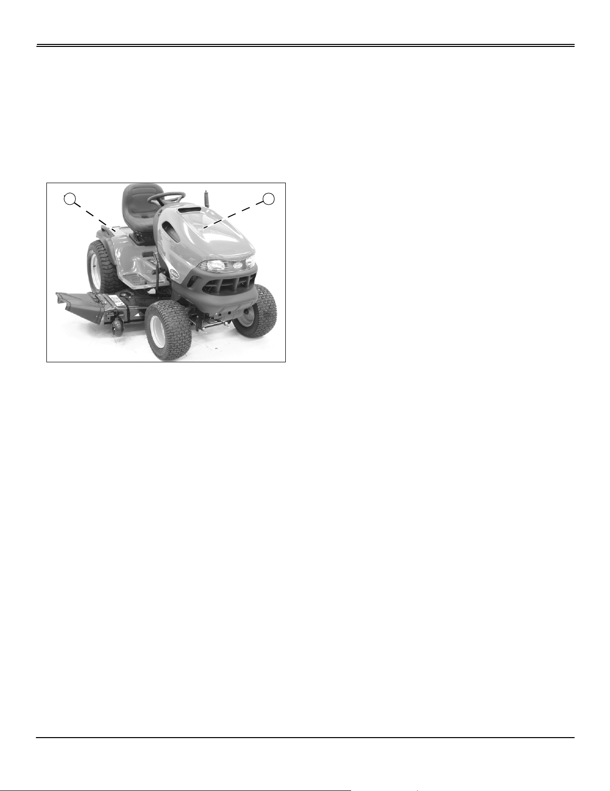
Record Identification Numbers
Scotts Garden Tractor
GT2554 Serial No. (GX2554S010001 - )
When contacting an Authorized Service Center for
information, always provide product model and seri al
number.
Locate identification number for machine and for engine.
Record information in spaces provided below.
A B
MX13481
DATE OF PURCHASE:
_________________________________________
DEALER NAME:
_________________________________________
DEALER PHONE:
_________________________________________
PRODUCT IDENTIFICATION NUMBER (A):
__ __ __ __ __ __ __ __ __ __ __ __ __ __ __ __ __
ENGINE SERIAL NUMBER (B):
__ __ __ __ __ __ __ __ __ __ __ __ __ __ __ __ __
Register Your Product and Warranty Online
To register your product through the Internet, simply go to
www.JohnDeereWarrantyRegistration.com. Completing the
information, either online or with the product warranty card,
will ensure th e c u st om er t hat t h ei r p ro d uc t r e ceives all post
sales service and important product information.
Product Identification

TABLE OF CONTENTS
Table of Contents
Safety .....................................................................................................................................................................................1
Assembly................................................................................................................................................................................8
Operating..............................................................................................................................................................................10
Replacement Parts................................ ....... ...... ....... ...... ....... ...... ....................................... .................................................21
Service Interval Chart...........................................................................................................................................................22
Service Lubrication...............................................................................................................................................................23
Service Engine .....................................................................................................................................................................24
Service Tr ansmission............................................................................................................................................................29
Service Mower......................................................................................................................................................................30
Service Electrical..................................................................................................................................................................34
Service Miscellaneous..........................................................................................................................................................37
Troubleshooting ....................................................................................................................................................................38
Storing Machine....................................................................................................................................................................42
Specifications .......................................................................................................................................................................44
Warranty...............................................................................................................................................................................46
Index.....................................................................................................................................................................................49
All information, illustrations and
specifications in this manual are based
on the latest information at the time of
publication. The right is reserved to
make changes at any time without
John Deere Worldwide Commercial and
Consumer Equipment Division
COPYRIGHT© 2001, 2000, 1999, 1998,
notice.
COPYRIGHT© 2002
Deere & Co.
All rights reserved
Previous Editions
1997
OMM139955 C2 - English
Table of Contents
SAFETY
Safety
Understanding Machine Safety Labels
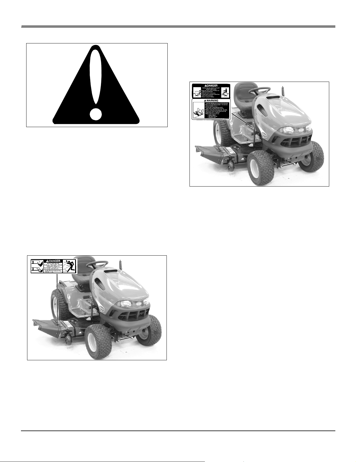
Safety-Alert Symbol
The machine safety labels shown in this section are placed
in important areas on your machine to draw attention to
potential safety hazards.
On your machine safety labels, the words DANGER,
WARNING, and CAUTION are used with this safety-alert
symbol. DANGER identifies the most serious hazards.
The operator’s manu al also explains any potential safety
hazards whenever necessary in special safety messages
that are identified with the word, CAUTION, and the safetyalert symbol.
grass catcher in place.
DANGER
ROTATING BLADES CUT OFF ARMS AND LEGS
M47707/MX13481
• Do not mow when children or others are around
• Do not mow in reverse
DANGER
Rotating Blade
MX13481
• Do not put hands or feet under or into mower when
engine is running.
• Look down and behind before and while backing
• Never carry children even with blades off
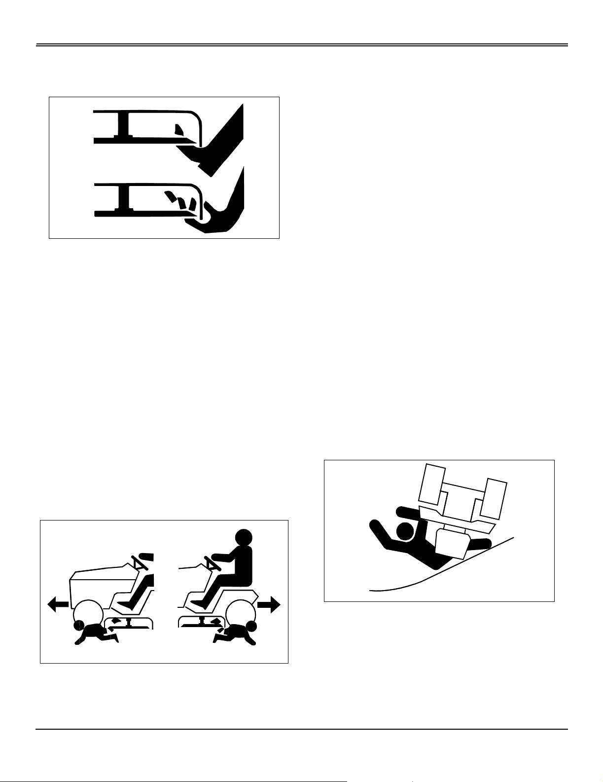
WARNING: AVOID SERIOUS INJURY OR DEATH
• Drive up and down slopes, not across
• Avoid sudden turns
• If machine stops going uphill, stop blade and back down
slowly
• Keep safety devices (guards, shields, and switches) in
place and working
• Read operator’s manual
• When leaving machine:
–Stop engine
–Set park brake
–Remove key
THROWN OBJECTS
• Befo re mowi ng, clea r area of objects that ma y be thro wn
by blade.
• Do not operate mower without discharge chute or entire
Safety - 1
SAFETY
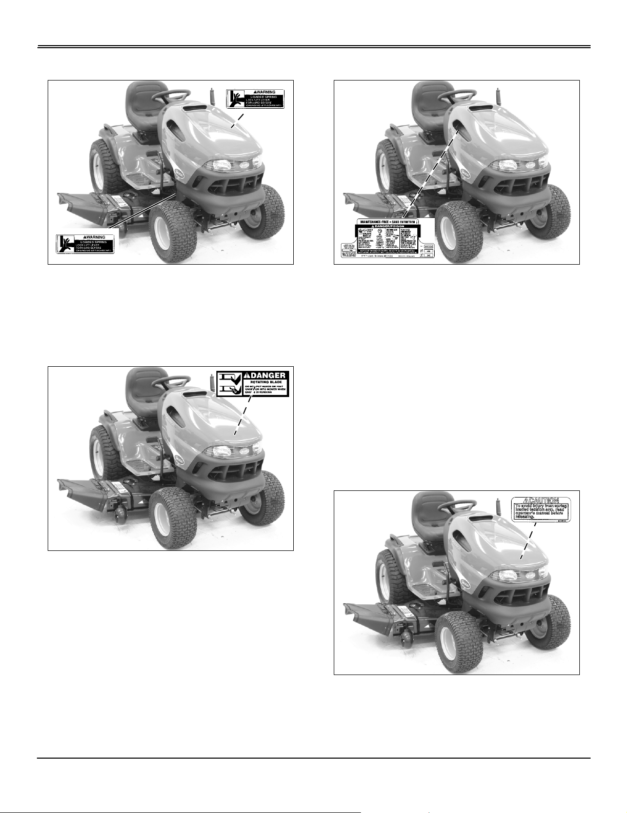
W ARNING: LOADED SPRING
M47589/M88552/MX13481
Lock lift lever forward before changing attachments.
DANGER
ROTATING BLADE
DANGER/POISON
MX13481
Picture Note: Located on battery
• Shield eyes. Explosive gases can cause blindness or
injury.
• No sparks, flames, smoking
• Sulfuric acid can cause blindness or severe burns
MX13481
Picture Note: Located on left side of mower
Do not put hands or feet under or into mower when engine
is running.
• Flush eyes immediately with water. Get medical help
fast.
• Maintenance-free.
• Keep out of the reach of children. Do not tip. Do not
open battery!
CAUTION
To avoid injury from spring loaded tension arm, read
operator’s manual before releasing.
Safety - 2
M138932/MX13481
SAFETY
Emission Control System Certification Label
NOTE: Tampering with emission controls and
components by unauthorized personnel may result in
severe fines or penalties. Emission controls and
components can only be adjusted by EP A and/or CARB
authorized service centers. Contact John Deere
Commercial and Consumer Equipment Retailer
concerning emission controls and component
questions.
The presence of an emissions label signifies that the
engine has been certified with the United States
Environmental Protection Agency (EPA) and/or California
Air Resources Board (CARB).
The emissions warranty applies only to those engines
marketed by John Deere that have been certified by the
EPA and/or CARB; and used in the United States and
Canada in off-road mobile equipment.
Emission Compliance Period
If engine has emission compliance category listed on the
emission control system certification or air index label, this
indicates the number of operating hours for which the
engine has been certified to meet EPA and/or CARB
emission requirements. The following table provides the
engine compliance period in hours associated with the
category found on the certification label.
Agency Category Hours
EPA C 250
EPA B 500
EPA A 1000
CARB Moderate 125
CARB Intermediate 250
CARB Extended 500
Operating Safely
• Read, understand and follow all instructions in the
manual, on the machine and on the safety video before
starting.
• Only allow responsible adults, who are familiar with the
instructions to operate the machine.
• Be thoroughly familiar with the controls and the proper
use of the machine before starting.
• Inspect machine before you operate. Be sure hardware
is tight. Repair or replace damaged, badly worn, or missing
parts. Be sure guards and shields are in good condition
and fastened in place. Make any necessary adjustments
before you operate.
• Do not operate mower without discharge chute or entire
grass catcher in place.
• Check brake action before you operate. Adjust or
service brakes as necessary.
• Stop machine if anyone enters the area.
• If you hit an object, stop the machine and inspect it.
Make repairs before you operate. Keep machine and
attachments properly maintained and in good working
order.
• Be aware of the mower discharge direction and make
sure that no one is in the path of the discharge direction.
• Do not leave machine unattended when it is running.
Certification
Your mower has been certified by an independent
laboratory for compliance with American National Standard
B-71.1, “Safety Specifications” for Power Lawn Mowers,
Lawn and Garden Tractors, and Lawn Tractors.
Safety - 3
• Only operate during daylight or with good artificial light.
• Be careful of traffic when operating near or crossing
roadways.
• Older adults are involved in a large percentage of riding
mower accidents involving injury. These operators should
evaluate their ability to operate a mower safely enough to
protect the operator and others from serious injury.
SAFETY
Rotating Blades are Dangerous
HELP PREVENT SERIOUS OR FATAL ACCIDENTS:
• Rotating blades can cut off arms and legs, and throw
objects. Failure to observe safety instructions could result
in serious injury or death.
• Keep hands, feet and clothing away from mower deck
when engine is running.
• Be alert at all times, drive forward carefully. People,
especially children can move quickly into the mowing area
before you know it.
• Before backing up, stop mower blades or attachments
and look down and behind the machine carefully, especially
for children.
• Do not mow in reverse.
adult.
• Never assume that children will remain where you last
saw them. Children are attracted to mowing activity, stay
alert to the presence of children.
• Keep children indoors when you are mowing. Turn the
machine off if a child enters the mowing area.
• Use extra care when you come to blind corners, shrubs,
trees, or other objects that may block your vision.
• Do not let children or an untrained person operate the
machine.
• Do not carry or let children ride on any attachment or
machine even with the blades off. Do not tow children in a
cart or trailer.
Parking Safely
• Stop machine on a level surface, not on a slope.
• Disengage mower blades.
• Lower attachments to the ground.
• Lock park brake.
• Stop engine.
• Remove key.
• Before leaving operator’s seat, wait for engine and all
moving parts to stop.
• Shut off blades when you are not mowing.
• Do not operate machine if you are under the influence of
drugs or alcohol.
• Park machine safely before inspecting, removing, or
unplugging mower or bagger.
PROTECT CHILDREN:
• Tragic accidents can occur if the operator is not alert to
the presence of children. Keep children out of the mowing
area and under the watchful care of another responsible
Avoid Tipping
• Slopes are a major factor related to loss-of-control and
tip-over accidents, which can result in severe injury or
death. All slopes require extra caution. If you cannot back
up the slope or if you feel uneasy on it, do not mow it.
• Keep all movement on slopes slow and gradual. Do not
make sudden changes in speed or direction.
• Slow down before you make a sharp turn or operate on
Safety - 4
SAFETY
a slope. Choose a low gear or speed so that you will not
have to stop or shift while on the slope.
• Do not turn on slopes unless necessary . Turn slowly and
turn downhill. Do not shift to neutral and coast downhill.
• Stay alert for holes and other hidden hazards in the
terrain. Uneven terrain could overturn the machine. Tall
grass can hide obstacles.
• Keep away from drop-offs, ditches and embankments.
• Use extra care with grass catchers or other
attachments. These can change the stability of the
machine. Do not use grass catcher on steep slopes.
• Use recommended weights for added stability when
operating on slopes or using front or rear mounted
attachments. Remove weights when not required.
• Drive up and down a hill - not across.
• Do not stop when going up hill or down hill. If machine
stops going up hill, disengage mower blades and back
down slowly.
• Mowing when grass is wet can cause reduced traction
and sliding.
• Do not try to stabilize the machine by putting your foot
on the ground.
Driving Safely on Public Roads
Avoid personal injury or death resulting from a collision with
another vehicle on public roads:
• Use safety lights and devices. Slow moving machines
when driven on public roads are hard to see, especially at
night.
• Whenever driving on public roads, use flashing warning
lights and turn signals according to local regulations. Extra
flashing warning lights may need to be installed.
Checking Mowing Area
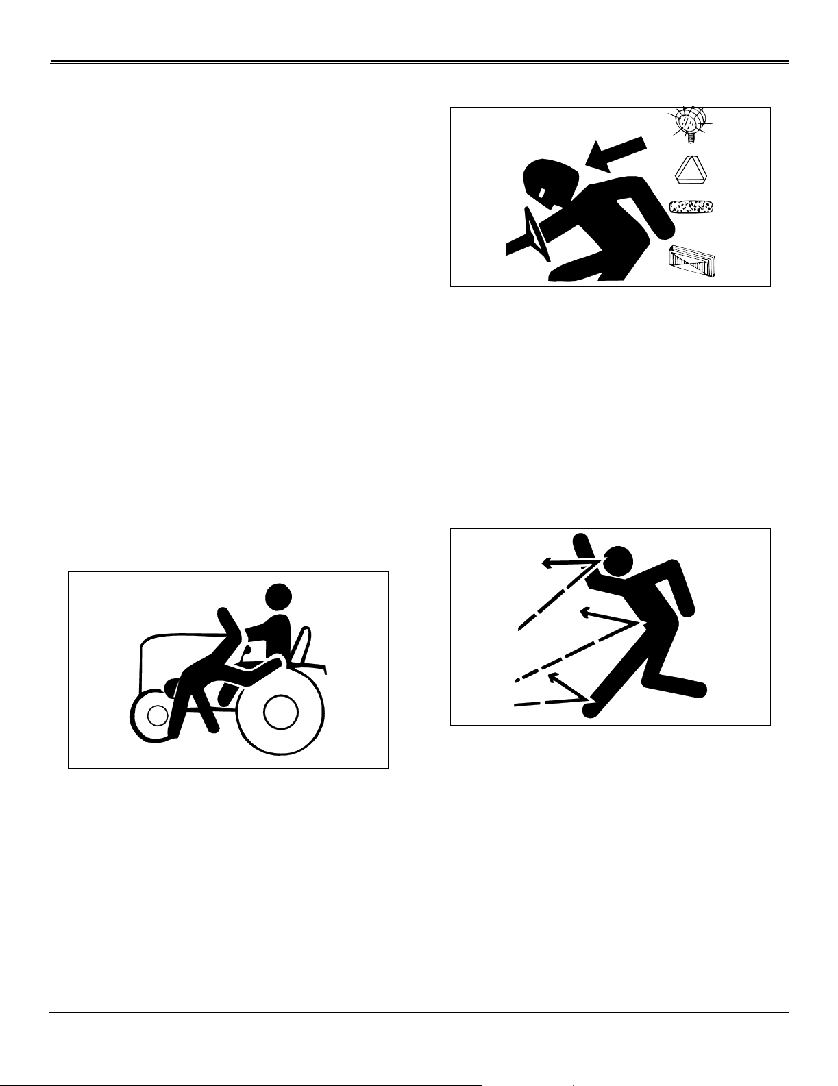
Keep Rider s Off
• Only allow the operator on the machine. Keep riders off.
• Riders on the machine or attachment may be struck by
foreign objects or thrown off the machine causing serious
injury.
• Riders obstruct the operator’s view resulting in the
machine being operated in an unsafe manner.
• Clear mowing area of objects that might be thrown.
Keep people and pets out of mowing area.
• Study mowing area. Set up a safe mowing pattern. Do
not mow where traction or stability is doubtful.
• Test drive area with mower lowered but not running.
Slow down when you travel over rough ground.
Towing Loads Safely
• Limit loads to those you can safely control. Use only
approved hitches when pulling loads or using heavy
equipment. Use counterweights or wheel weights as
required in this manual or your attachment manual.
Safety - 5
SAFETY
• Do not tow children in a cart or trailer.
• Travel slowly and allow extra distance to stop.
• Follow the manufacturer’s recommendation for weight
limits for towed equipment and towing on slopes.
• Tow only with a machine that has a hitch designed for
towing. Do not attach towed equipment except at the hitch
point.
• On slopes, the weight of towed equipment may cause
loss of traction and loss of control.
Wear Appropri ate Clothing
• Remove grass and debris from engine compartment
and muffler area, before and after operating machine,
especially after mowing or mulching in dry conditions.
• To reduce fire hazard, keep engine and engine
compartment free of grass, leaves, or excessive grease.
• Allow engine to cool before storing in any enclosure.
• Never remove fuel cap, or add fuel with engine running
or hot. Allow engine to cool for several minutes.
• Never store equipment with fuel in the tank inside a
building where fumes may reach an open flame or spark.
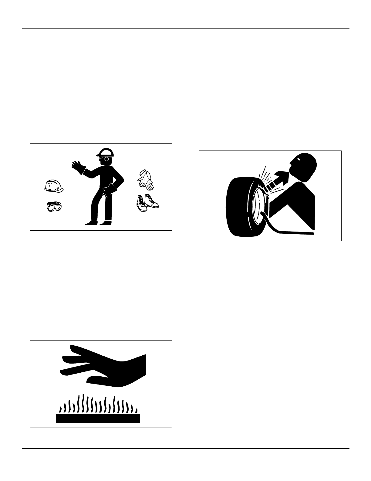
Tire Safety
• Always wear safety goggles or safety glasses with side
shields when operating the mower.
• Wear close fitting clothing and safety equipment
appropriate for the job.
• Wear a suitable protective device such as earplugs.
Loud noise can cause impairment or loss of hearing.
• Do not wear radio or music headphones. Safe service
and operation requires your full attention.
Prevent Fires
Explosive separation of a tire and rim par ts can ca use
serious injury or death:
• Do not attempt to mount a tire without the proper
equipment and experience to perform the job.
• Always maintain the correct tire pressure. Do not inflate
the tires above the recommended pressure. Never weld or
heat a wheel and tire assembly. The heat can cause an
increase in air pressure resulting in a tire explosion.
Welding can structurally weaken or deform the wheel.
• When inflating tires, use a clip-on chuck and extension
hose long enough to allow you to stand to one side and
NOT in front of or over the tire assembly.
• Check tires for low pressure, cuts, bubbles, damaged
rims or missing lug bolts and nuts.
Safety - 6
SAFETY
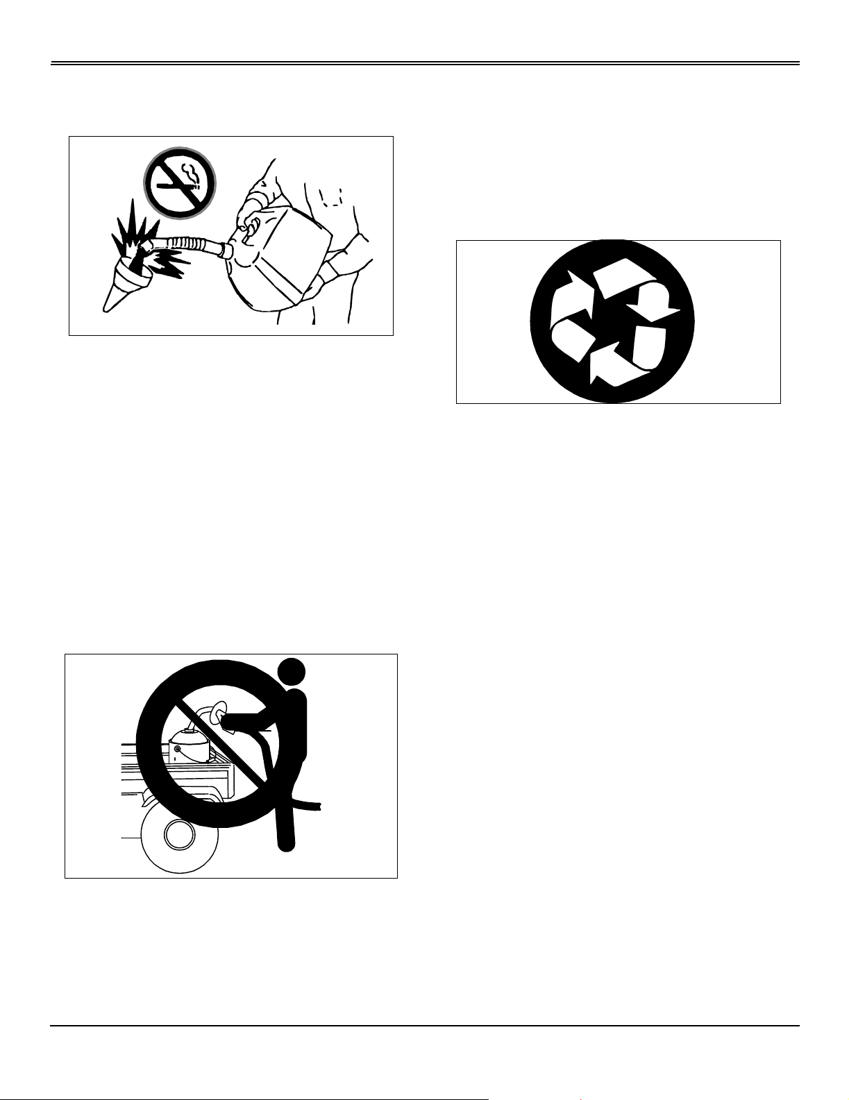
Handling Fuel Safely
Fuel and fuel vapors are highly flammable:
• Do not refuel machine while you smoke, when machine
is near an open flame or sparks, or when engine is running.
stop engine and allow to cool before filling.
• Never remove the fuel cap or add fuel with the engine
running.
• Never fill fuel tank or drain fuel from a machine in an
enclosed area. Fill fuel tank outdoors.
• Prevent fires. Clean up spilled fuel immediately.
• Do not store machine with fuel in tank in a building
where fumes may reach an open flame or spark.
• Prevent fire and explosion caused by static electric
discharge. Use only non-metal, portable fuel containers
approved by the Underwriter’s Laboratory (U.L.) or the
American Society for Testing & Materials (ASTM). If using a
funnel, make sure it is plastic and has no screen or filter.
beds and refuel them on the ground. If this is not possible,
use a portable, plastic fuel container to refuel equipment on
a truck bed or trailer.
• For gasoline engines, do not use gas with methanol.
Methanol is harmful to your health and to the environment.
Handling Waste Product and Chemicals
Waste products, such as, used oil, fuel, coolant, brake fluid,
and batteries, can harm the environment and people:
• Do not use beverage containers for waste fluids someone may drink from them.
• See your local Recycling Center or John Deere dealer to
learn how to recycle or get rid of waste products.
• A Material Safety Data Sheet (MSDS) provides specific
details on chemical products: physical and health hazards,
safety procedures, and emergency response techniques.
The seller of the chemical products used with your machine
is responsible for providing the MSDS for that product.
• Static electric discharge can ignite gasoline vapors in an
ungrounded fuel container. Remov e the fuel container from
the bed of a vehicle or the trunk of a car and place on the
ground away from the vehicle before filling. Keep nozzle in
contact with container opening while filling.
• When practical, remove equipment from trailers or truck
Safety - 7
ASSEMBLY
Assembly
Identify Parts
Clear Plastic Bag Contains:
• Operator’s Manual
• Safety Video
• Warranty Cards
Bag of Parts Contains:
• Hardware for Steering Wheel
• Hardware for Battery Cables
• Key Chain
• Padded Key
NOTE: There is an ex tra ignition ke y strapped to one of
seat suspension springs.
Install Steering Wheel
1. Put front wheels in straight forward position.
2. Lubricate steerin g shaf t.
3. Install steering wheel with logo in upright position.
B
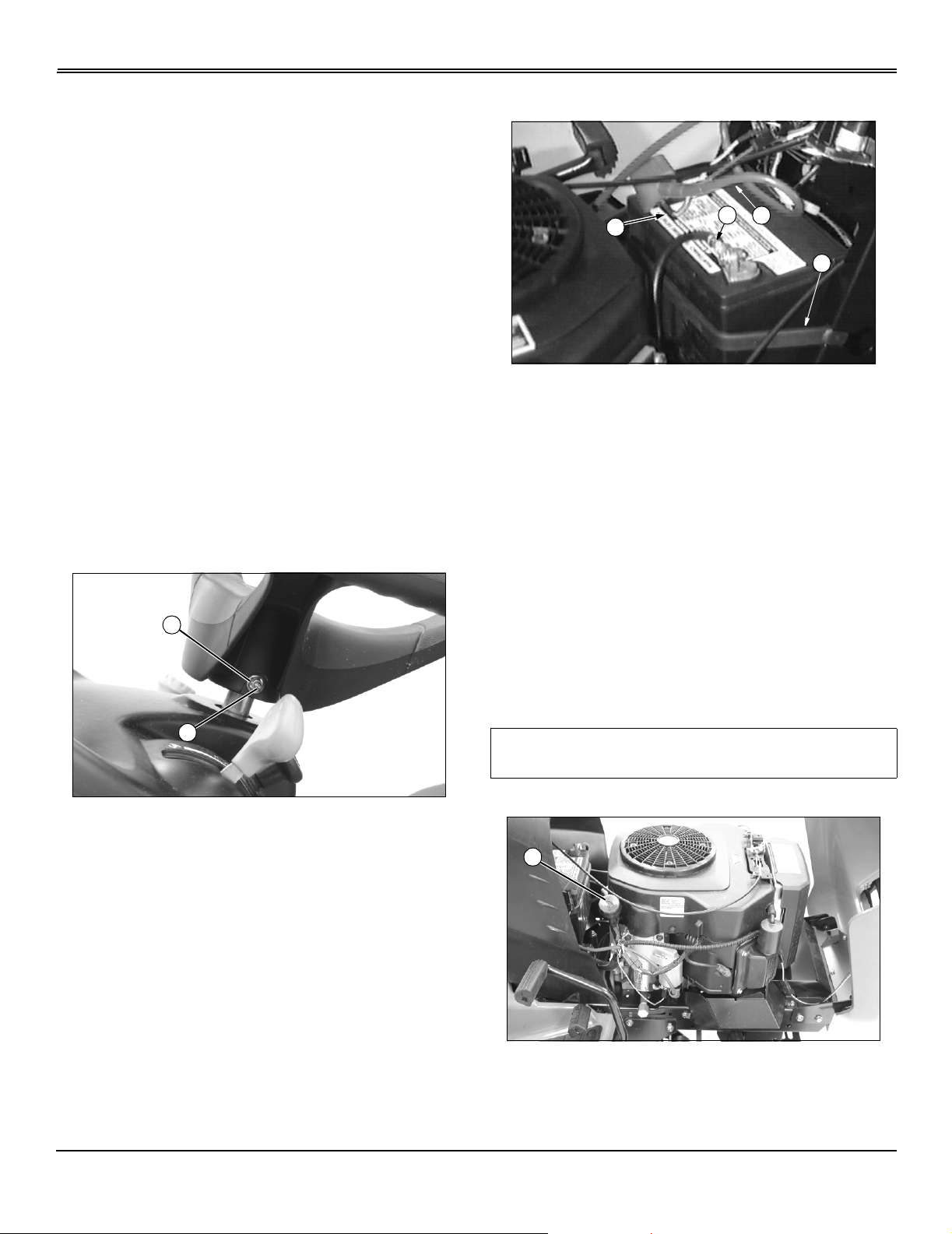
Install and Connect Battery
D
B
1. Install battery and secure with hold-down strap (A)
2. Remove and discard red positive (+) protective cap from
positive (+) battery terminal.
3. Connect blue harness wire (B) and red positive (+) cable
(C) to battery. Apply petroleum jelly or silicone spray to
terminal to prevent corrosion. Make sure connection is
tight. Install red terminal cover.
4. Remove and discard black (–) protective cap from
negative battery terminal.
5. Connect black negative (–) cable (D) to battery. Apply
petroleum jelly or silicone spray to terminal to prevent
corrosion. Make sure connection is tight.
C
A
M88565
A
MX13512
4. Install shoulder bolt (A). Drive bolt in until head of bolt
contacts steering wheel.
5. Install washer and nut (B).
6. Tighten lock nut until it is snug. Do not tighten lock nut to
pull washer or head of bolt into steering wheel.
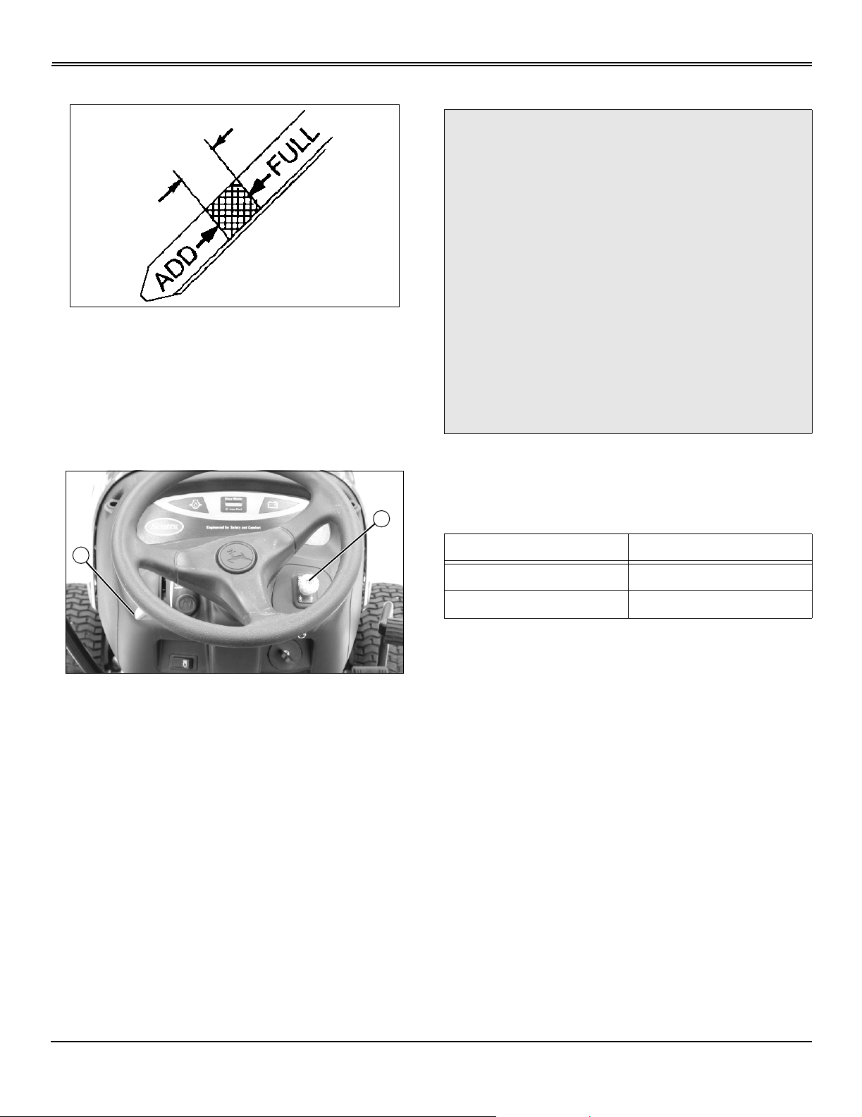
Check Engine Oil
IMPORTANT: Avoid damage! Do not run engine if oil
level is below add mark.
1. Lift hood.
A
MX13511
2. Remove dipstick (A). Wipe with clean cloth.
3. Insert dipstick into tube and rest oil fill cap on tube. Do
not thread cap onto tube.
Assembly - 8
ASSEMBLY
4. Remove dips tick to check oil level.
5. Oil must be between add and full marks.
6. Add oil to full mark if necessary. Do not overfill.
7. Install and tighten dipstick. Lower hood.
Break-In Electric PTO Clutch
Checking Tire Pressure
c CAUTION: Avoid injury! Explosive separation
of tire and rim parts is possible when they are
serviced incorrectly:
• Do not attempt to mount a tire without the
proper equipment and experience to perform
the job.
• Do not inflate the tires above the
recommended pressure.
• Do not weld or heat a wheel and tire
assembly. Heat can cause an increase in air
pressure resulting in an explosion. Welding
can structurally weaken or deform the wheel.
• Do not stand in front or over the tire
assembly when inflating. Use a clip-on chuck
and extension hose long enough to allow you
to stand to one side.
1. Check tires for damage.
2. Check tire pressure with an accurate gauge.
3. Add or remove air, if necessary:
B
A
MX13482
1. Start engine and push throttle lever (A) up to full throttle
(r) position.
2. With no load on mower, engage PTO (B) and allow
mower to run for 10 seconds.
3. Disengage PTO and wait 10 seconds.
4. Repeat Steps 2 and 3 for 12-15 cycles.
5. PTO clutch is now properly burnished.
Check Machine Safety System
Perform safety system check to make sure electronic safety
interlock circuit is functioning properly. Perform all safety
system tests.
Tire Size Air Pressure
Front: 16 x 7.50 83 kPa (12 psi)
Rear: 24 x 12.00 69 kPa (10 psi)
Assembly - 9
Operating
Daily Operating Checklist
• Test safety systems.
• Check tire pressure.
• Check fuel level.
• Check engine oil level.
OPERATING
B
A
C
• Remove grass and debris from engine compartment
and muffler area, before and after operating machine.
Avoid Damage to Plastic and Painted Surfaces
• Do not wipe plastic parts unless rinsed first. (See
Correct Cleaning Care in Service-Miscellaneous section.)
• Insect repellent spray may damage plastic and painted
surfaces. Do not spray insect repellent near machine.
• Be careful not to spill fuel on machine. Fuel may
damage surface. Wipe up spilled fuel immediately.
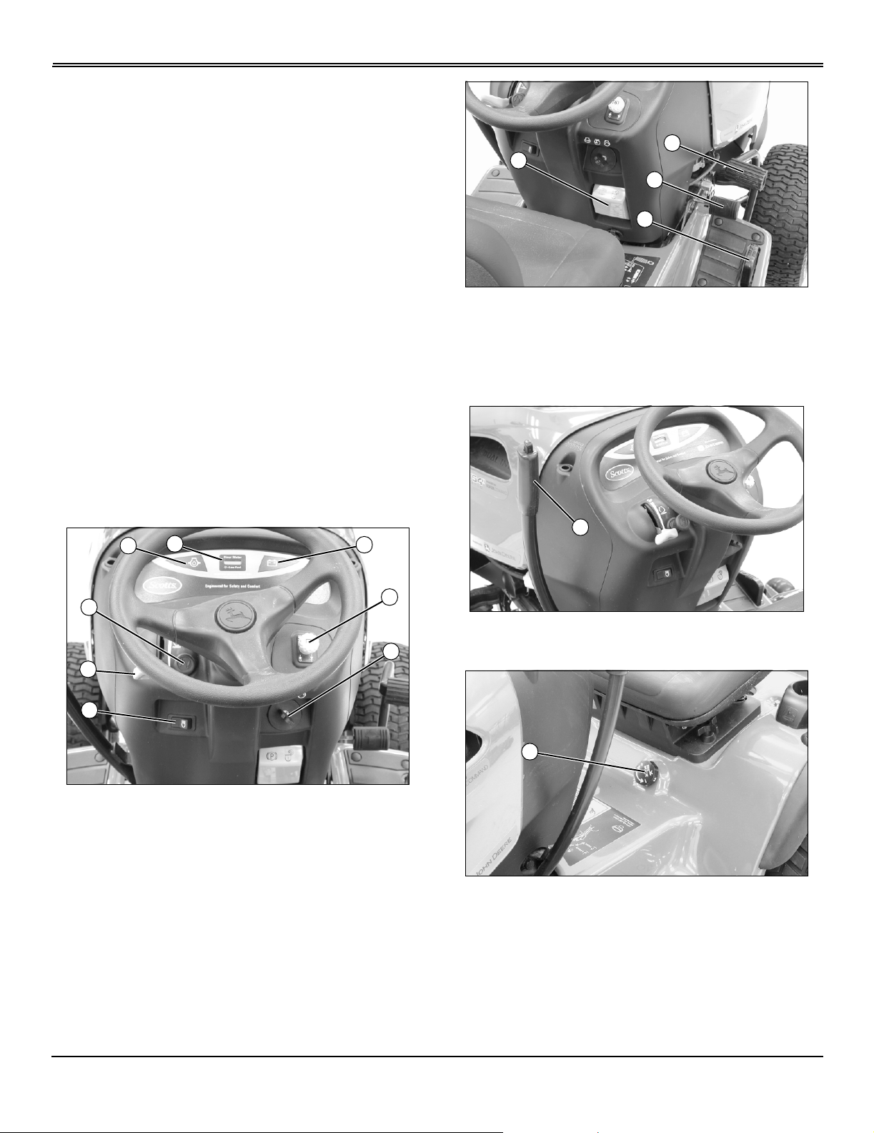
Operator Station Controls
F
D
E
G
H
B
C
D
MX13483
A - Park Brake Lever
B - Brake Pedal
C - Forward Travel Pedal
D - Reverse Travel Pedal
A
MX13484
A - Mower Lift Lever
A
A - Light Switch
B - PTO Switch/RIO Switch
C - Key Switch
D - Choke Knob
E - Throttle Lever
F - Engine Oil Pressure Light
G - Hour Meter
H - Battery Discharge Light
A
MX13482
MX13485
A - Cut Height Adjustment Lever
Operating - 10
OPERATING
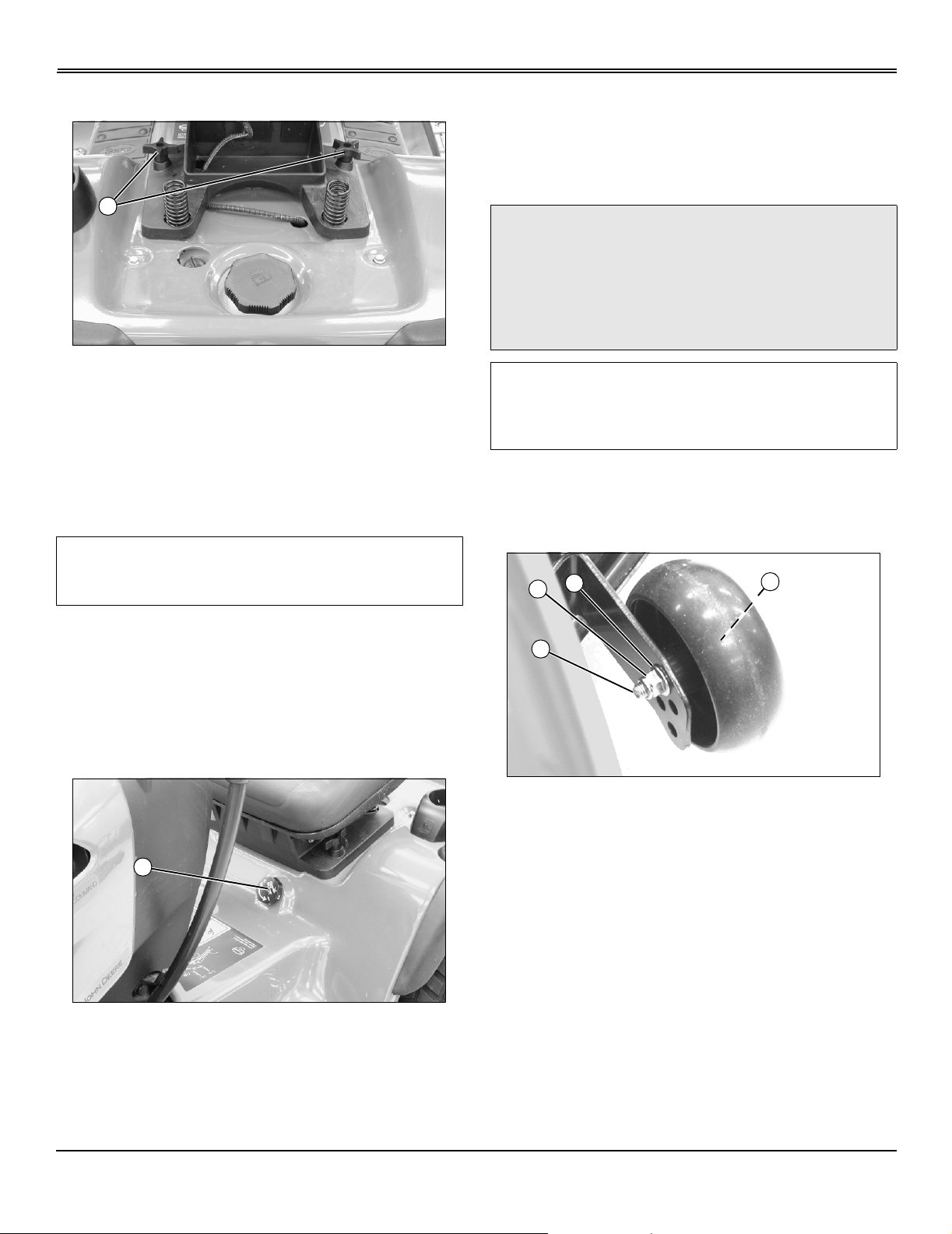
Adjusting Seat
A
MX13486
1. Tip seat forward and loosen two knobs (A) to slide seat
assembly forward or rearward to most comfortable operator
position.
2. Tighten knobs after adjustment to keep seat in place.
Adjusting Cutting Height
IMPORTANT: Avoid damage! Lift lever must be in
TRANSPORT (upper) position bef ore turning cut ting
height knob.
position. Mower will be at this cutting height each time it is
lowered.
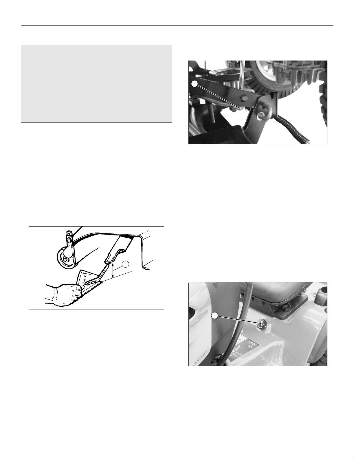
Adjusting Mower Gage Wheels
c CAUTION: Avoid injury! Before adjusting gage
wheels:
Stop engine.
Remove key.
Wait for blades to stop.
IMPORTANT: Avoid damage! Mower gage wheels
must not ride on ground to support mower weight.
Adjust gage wheels each time cutting height is
changed.
1. Check machine tire pressure. Inflate tires to correct
pressure.
2. Raise mower lift lever to transport (upper) position and
adjust cutting height.
C
D
A
NOTE: Adjust mower gage wheels after changing
cutting height.
Cutting height can be adjusted from approximately 25–100
mm (1–4 in.).
When lift lever is in transport (upper) position (lift lever
completely back), cutting height is approximately 100 mm
(4 in.).
A
MX13485
Knob (A) has cutting height identificati on numbers
embossed in it. To change or attain cutting height desired:
• Pull lift lever completely back to transport (upper)
position.
A
MX13506
3. Remove bolt (A), bushing (B), washer (C), and tighten
with nut (D).
4. Move mower gage wheels, one on each side, to one of
four holes for desired position.
5. Install bolt and tighten with nut.
6. Move lift lever forward to mowing (lower) position.
7. Bottom of gage wheels should be approximately 6-13
mm (1/4-1/2 in.) from ground when properly adjusted.
• Turn cutting height knob (A) to desired cutting height
Operating - 11
OPERATING
Adjusting Mower Level (Side-to-Side)
c CAUTION: Avoid injury! Before adjusting gage
wheels:
Stop engine.
Remove key.
Wait for blades to stop.
Be careful of sharp edges on mower blades.
Always wear gloves when handling mower
blades.
NOTE: A mo wer lev eling gauge (P art Number TY15272)
to aid in mower leveling may be obtai ned through a
local John Deere dealer.
1. Park machine safely. (See Parking Safely in the Safety
section.)
2. Check tire pressure.
3. Adjust cutting height to 50 mm (2 in.).
NOTE: Mower gage wheels should not contact ground.
4. Put mower lift lever in mowing (lower) position.
5. Turn left blade by hand parallel to machine axle. Hold
drive belt and turn right blade parallel to axle.
NOTE: Adjustable lift links are on both sides of mower.
Cutting height can closel y matc h knob setting b y using
adjustment on both sides. Do not adjust mower too
high or it will not lock in transport (upper) position.
B
MX13507
7. Turn nut (B), (left side shown): Clockwise to raise left
side of mower and counterclockwise to lower left side of
mower .
8. Check side-to-side measurements and adjust if
necessary.
Adjusting Mower Level (Front-to-Rear)
NOTE: Mower gage wheels should not contact ground
during leveling.
1. Park machine safely. (See Parking Safely in the Safety
section.)
A
M40161
6. Measure from each outside blade tip (A) to level surface.
Difference between measurements must not be more than
3 mm (1/8 in.).
2. Tire pressure must be correct.
3. Pull lift lever completely back to transport (upper)
position.
A
MX13485
4. Turn mower depth control knob (A) to adjust cutting
height to 50 mm (2 in.).
5. Move lift lever forward to mowing (lower) position.
6. Turn left blade so blade tip points straight forward.
7. Hold drive belt and turn right blade straight forward.
Operating - 12
OPERATING
8. Measure from front of each blade tip to level surface.
Front blade tips must be 6–9 mm (1/4–3/8 in.) lower than
rear blade tips or blades will cut grass twice and tips will
turn brown.
B
C
9. Loosen two rear nuts (B) on front lift rod assembly and
turn two front nuts (C) clockwise to raise front of mower or
counterclockwise to lower front of mower.
10.Tighten rear nuts (B) after adjustment is completed.
11.Check front-to-rear mower measurements and adjust if
necessary.
B
M88578
c CAUTION: Avoid injury! Engine exhaust fumes
contain carbon monoxide and can cause
serious illness or death.
Move the vehicle to an outside area before
running the engine.
Do not run an engine in an enclosed area
without adequate ventilation.
• Connect a pipe extension to the engine
exhaust pipe to direct the e xhaust f umes out of
the area.
• Allo w fresh outside air into the work area to
clear the exhaust fumes out.
Use the following checkout procedure to check for normal
operation of machine.
If there is a malfunction during one of these procedures, Do
not operate machine. See your John Deere dealer for
service.
Perform these tests in a clear open area. Keep bystanders
away.
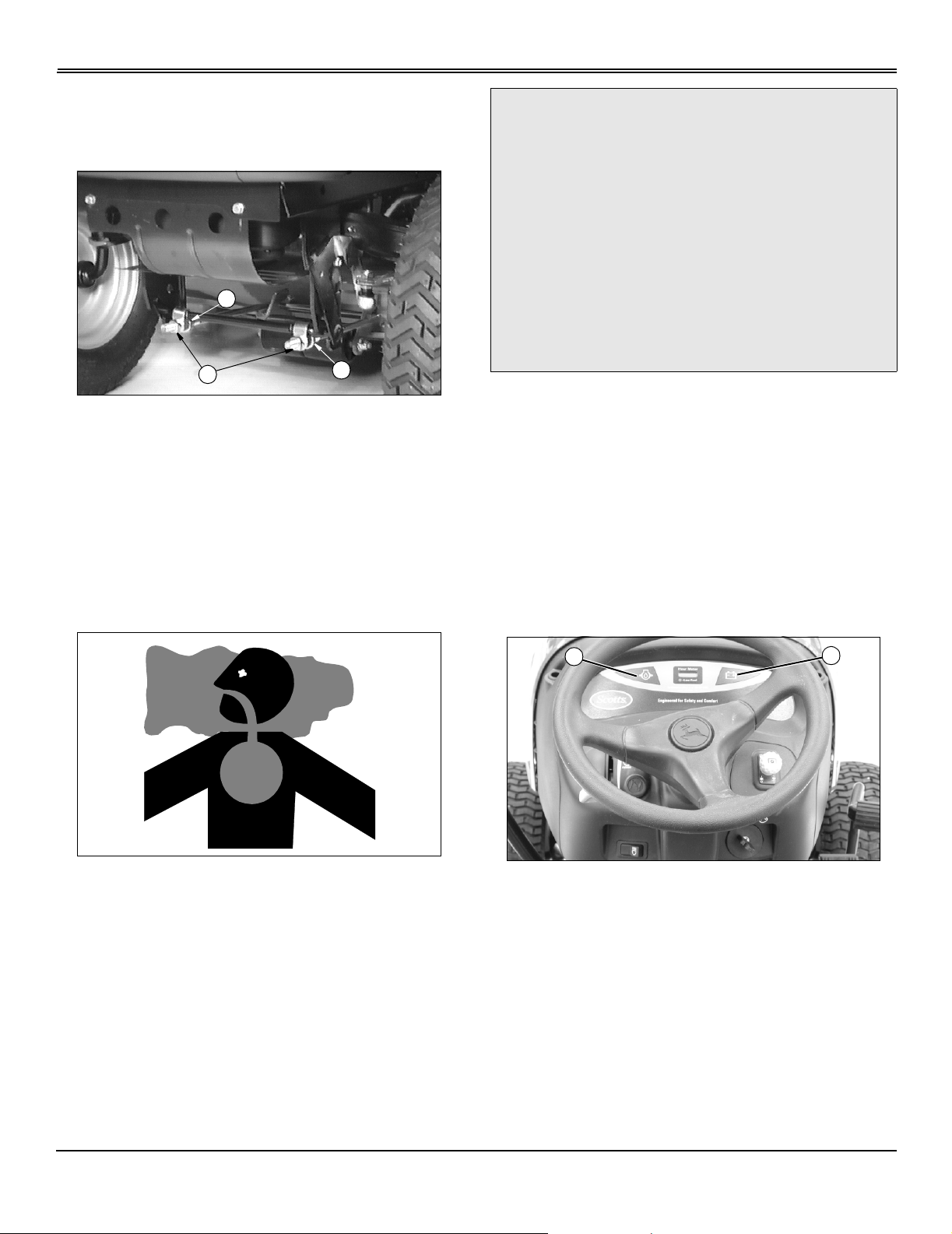
Testing Safety Systems
Testing Indicator Lights
1. Turn key to run position.
A
2. Look:
• Oil pressure light (A) on must light.
• Battery discharge light (B) will momentarily light, this
indicates that system is functioning properly. If light
remains on, start engine and move throttle to high idle.
Light should go out.
NOTE: Battery discharge light may remain on for
several minutes while battery is being charged.
B
MX13482
3. If one indicator does not light, replace.
4. If new indicator bulb does not light or no indicators work,
see John Deere dealer for service.
Operating - 13
 Loading...