

Page 1

User Guide Delivery Instructions
User Guide
Activations
Set date and time prior to entering Activation codes to ensure
the Activations will be acknowledged.
Data Transfer
Apex version 3.2 or newer is required to transfer data to the
GS3 2630 from a different John Deere Display model (i.e. GS2
1800, GS2 2600, GS3 CommandCenter).
Coverage and Swath Control Maps cannot be transferred from
a different John Deere Display model.
User Guide
This User Guide is intended to assist the operator with com-
mon operations. See the Operator Manual for detailed information.
GS2 1800 Display
1
GS2 1800 Display
Page 2

User Guide Delivery Instructions
User Guide
GS2 1800 Display
2
GS2 1800 Display
Page 3
GreenStar™ 2
1800 Display
PFP11809
Page 4

About This Document
This User Guide will help you learn how to perform common tasks with
your new display. It is a supplement to the display Operator’s Manual.
Read the Operator’s Manual for the following information:
• How to operate your display safely
• Theory of operation
• How to install the display and do initial setup
• Diagnostics
Copyright © 2012 Deere & Company. All Rights Reserved. THIS MATERIAL IS THE
PROPERTY OF DEERE & COMPANY. ALL USE AND/OR REPRODUCTION NOT
SPECIFICALLY AUTHORIZED BY DEERE & COMPANY IS PROHIBITED. All information,
illustrations and specifications in this manual are based on the latest information available
at the time of publication. The right is reserved to make changes at any time without notice.
Page 5

User Guide Display General
User Guide
Section Contents
TURNING THE DISPLAY ON/OFF ...................................... 2
Turn ON the display.............................................................................. 2
Turn OFF the display............................................................................ 2
HOME PAGES ..................................................................... 3
Accessing Home Page Setup............................................................... 3
Adding Home Pages............................................................................. 3
Changing the Left Hand Region ........................................................... 4
GS2 1800 Display
1
GS2 1800 Display
Page 6

User Guide Display General
User Guide
Turning the Display On/Off
The display will turn on and off with the vehicle key switch.
Turn ON the display
1. Turn vehicle key switch directly to the Run position.
IMPORTANT: Do NOT allow the display to boot up with the key
in Accessory Mode and then crank the engine.
NOTE: Implement controllers may take several minutes to load (if
connected).
Turn OFF the display
Turn vehicle key switch to shut down vehicle and wait for the display to
save settings.
IMPORTANT: Never pull the power plug without first turning
off the vehicle key switch. Data loss could occur.
NOTE: The display requires a constant power source, so that it can save
data and settings after the key is switched off. The Status LED is amber
while the display saves data and settings.
GS2 1800 Display
2
GS2 1800 Display
Page 7
User Guide Display General
User Guide
Home Pages
Home Pages are used to quickly cycle through commonly viewed pages.
The map page is included in the cycle by default.
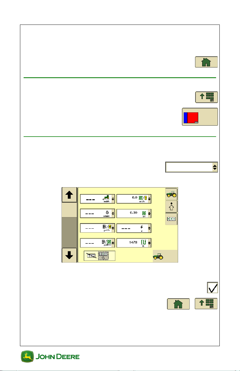
• Select Home to view each Home Page .......................
Accessing Home Page Setup
1. Menu ............................................................................
2. Layout Manager ..................................................
Adding Home Pages
Three additional pages can be added to the Home Pages cycle.
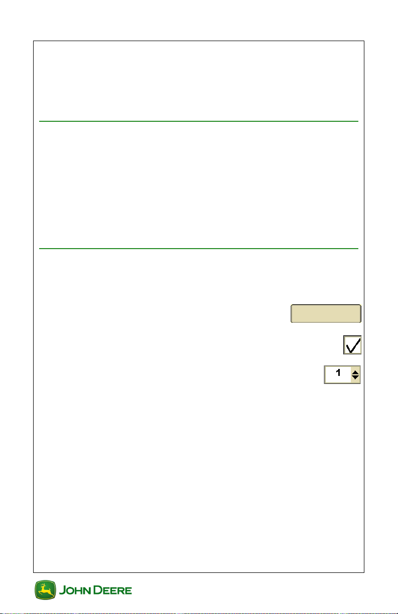
1. Select a Home Page from the list box .........
• A preview of the selected Home Page is shown on the screen.
2. Use the thumb wheel to scroll between the different Home
Page options.
3. Check the box to save the page to the Home Page cycle ..
4. Select Home or Menu to exit ........................
GS2 1800 Display
3
GS2 1800 Display
Page 8

User Guide Display General
User Guide
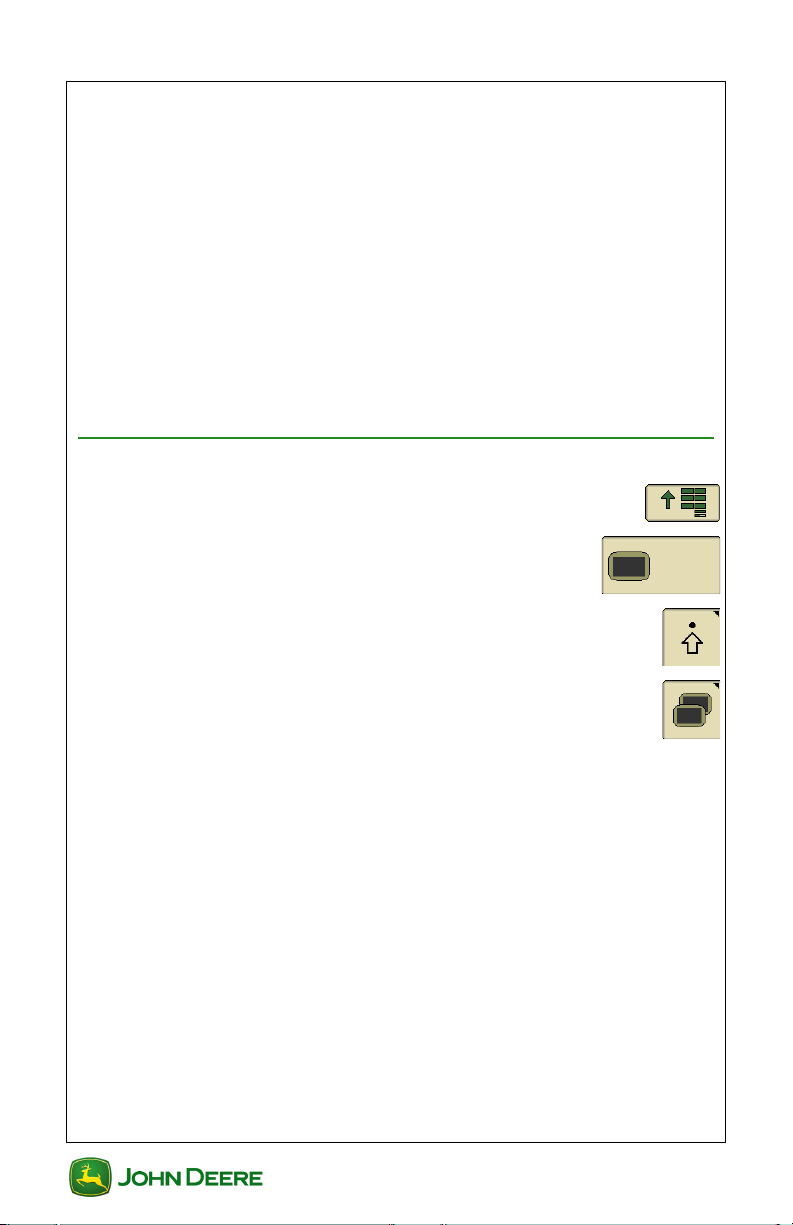
Changing the Left Hand Region
There are several page options to be displayed in the Left Region of the
screen. The left hand region will remain constant when the main region of
the screen changes.
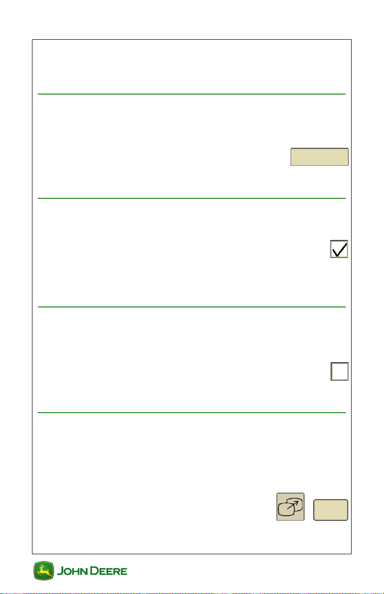
1. In Layout Manager, Select Left Region
from list box.
2. Use the thumb wheel to scroll between the Left Region options.
GS2 1800 Display
4
GS2 1800 Display
Page 9

User Guide Dual Display
User Guide
Section Contents
GETTING STARTED............................................................ 2
Accessing Multiple Display Settings ..................................................... 2
MODEL YEAR 2010 8R COMMANDCENTER .................... 3
Connecting a Second Display .............................................................. 3
Changing Multiple Display Settings ...................................................... 3
GS3 COMMANDCENTER.................................................... 4
Connecting a Second Display .............................................................. 4
Changing Multiple Display Settings ...................................................... 4
TROUBLESHOOTING TIPS ................................................ 6
Restore Settings before Making Adjustments ...................................... 6
Allow Controller to Appear on the CommandCenter ............................ 6
Force All Controllers to Appear in the Second Display......................... 6
Other Tips (Next VT, Change VT) ........................................................ 6
GS2 1800 Display
1
GS2 1800 Display
Page 10
User Guide Dual Display
User Guide
Getting Started
This section includes tips for using two John Deere ISOBUS displays
together in Model Year 2010 and newer John Deere vehicles. In dual
display mode, the 8R and GS3 CommandCenters are compatible with the
following displays:
GS2 1800
GS2 2600
GS3 2630
Using two displays allows the operator to monitor the implement on one
display and run functions like guidance, section control, and
documentation on the other.
Accessing Multiple Display Settings
1. Menu ............................................................................
2. Display ..................................................................
3. Settings softkey ..............................................................
4. Multiple Displays softkey ...............................................
GS2 1800 Display
2
GS2 1800 Display
Page 11
User Guide Dual Display
User Guide
Model Year 2010 8R CommandCenter
The 8R CommandCenter was introduced for the 2010 model year 8R
Tractors. The 8R CommandCenter does not have GreenStar capabilities
(such as AutoTrac) on the display and therefore, no multiple display setup
is required.
Connecting a Second Display
1. With key switched OFF, connect the display to the corner post
harness connector.
2. Switch key ON to start vehicle and power the displays.
Changing Multiple Display Settings
Only the Implement Bus Virtual Terminal setting should be changed by
the operator.
• On/Off checkbox – check the box to enable the setting on
the CommandCenter.
• Function Instance – Refer to ISO Implement or ISO
Display Manual for necessary adjustments.
Multiple Display Settings options are described below:
• Implement Bus Virtual Terminal – Allows communication
between the CommandCenter and a controller (e.g. Receiver,
SeedStar II).
▪ Check box ON to allow a controller to run on the Com-
mandCenter.
▪ Check box OFF to allow a controller to run on another
connected display.
NOTE: Cycle power for changes to save and take effect.
GS2 1800 Display
3
GS2 1800 Display
Page 12
User Guide Dual Display
Change Settings
User Guide
GS3 CommandCenter
The GS3 CommandCenter was introduced with Model Year 2011 Rseries tractors and Model Year 2012 S-series combines. The GS3
CommandCenter has GreenStar capabilities (such as AutoTrac) built into
the display.
Connecting a Second Display
To use a second display as a companion to the GS3 Com-
mandCenter, please do the following:
• With key switched OFF, connect the display to the corner post
harness connector.
• Switch key ON to start vehicle and power the displays.
• Follow the instructions on the GS3 CommandCenter screen.
Changing Multiple Display Settings
Multiple Display Settings options can be adjusted by the oper-
ator:
1. Select Change Settings ...................................
Multiple Display Settings options are described below:
• On/Off checkbox - check the box to enable the setting on
the GS3 CommandCenter.
• Function Instance - Refer to ISO Implement or ISO Display Manual for necessary adjustments.
• GreenStar – No adjustment required. GreenStar will run on the
second connected John Deere display.
• Original GreenStar Monitor – No adjustment required. Original
GreenStar Monitor will run on the second connected John Deere
display.
• Implement Bus – Allows communication between the GS3 CommandCenter and controller (e.g. Receiver, SeedStar II).
▪ Check box ON to allow a controller to appear on the
CommandCenter.
▪ Check box OFF to allow a controller to appear on
another connected display.
GS2 1800 Display
4
GS2 1800 Display
Page 13

User Guide Dual Display
Save Settings and
Restart Display
User Guide
• Vehicle Bus – No adjustment required.
2. Select Save Settings and Restart Display ........
GS2 1800 Display
5
GS2 1800 Display
Page 14
User Guide Dual Display
Restore Factory
Default Settings
Change VT
User Guide
Troubleshooting Tips
The following information may be helpful for managing which display will
run a controller (e.g. StarFire Receiver, SeedStar II).
Restore Settings before Making Adjustments
Default settings should be restored before attempting any
other troubleshooting tips.
• Select Restore Factory Default Settings ...........
NOTE: This option will not appear if settings are already set to default.
Allow Controller to Appear on the CommandCenter
A controller does not appear. Try the following steps:
1. Ensure the Implement Bus is turned ON in the
CommandCenter.
2. Cycle power of the display.
NOTE: If the controller does not appear, check all harness connections.
Force All Controllers to Appear in the Second Display
A controller appears on the opposite display. Try the following:
1. Select the Implement Bus checkbox.
2. Ensure the Implement Bus is turned OFF in the
3. Cycle power of the display.
Other Tips (Next VT, Change VT)
If you desire for a specific controller to run on another display,
1. Navigate to the appropriate controller page.
2. Select Next VT or Change VT ..........................
CommandCenter.
some controllers may be capable of moving to the display
without the use of Multiple Display Settings.
GS2 1800 Display
6
GS2 1800 Display
Page 15

User Guide GreenStar General
User Guide
Section Contents
GETTING STARTED............................................................ 2
Access GreenStar Applications ............................................................ 2
GreenStar Activations........................................................................... 2
What Needs to Be Set Up .................................................................... 2
Using the Setup Wizard ........................................................................ 2
Change Field Name.............................................................................. 3
MACHINE SETUP ................................................................ 4
Machine Offsets.................................................................................... 4
Connection Type Examples.................................................................. 5
IMPLEMENT SETUP............................................................ 6
Implement Offsets ................................................................................ 6
Coverage Recording Source ................................................................ 8
DATA MANAGEMENT......................................................... 9
Backup Data from the Display .............................................................. 9
Importing Data to the Display ............................................................. 10
View Memory Remaining.................................................................... 11
Transferring Data between Two Displays........................................... 11
Data Cleanup...................................................................................... 12
RECORD A BOUNDARY................................................... 13
This Chapter pertains to GreenStar™ applications including, but not
limited to AutoTrac™ and Swath Control.
GS2 1800 Display
1
GS2 1800 Display
Page 16
User Guide GreenStar General
User Guide
Getting Started
Access GreenStar Applications
All information and functionality related to GreenStar applications is
accessed with the GreenStar Softkey.
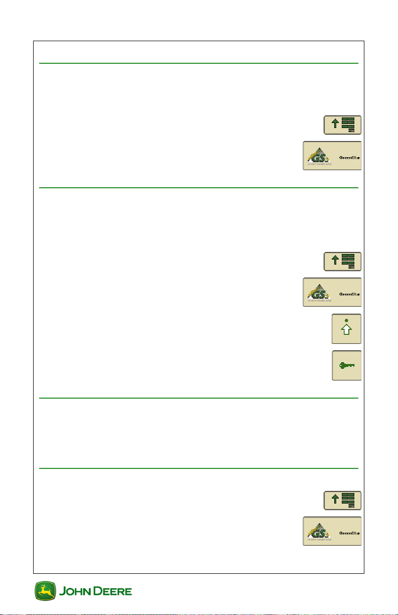
1. Menu ............................................................................
2. GreenStar ..............................................................
GreenStar Activations
Activations are required for GreenStar applications other than Manual
Guidance. Check the Activations page to see if an Application is Activated
and checked ON.
1. Menu .............................................................................
2. GreenStar ..............................................................
3. Settings Softkey .............................................................
4. Activations .....................................................................
What Needs to Be Set Up
The amount of setup information that must be entered depends on the
applications being used. A Setup Wizard is available to guide you through
each setup page.
Using the Setup Wizard
1. Menu ............................................................................
2. GreenStar ..............................................................
GS2 1800 Display
2
GS2 1800 Display
Page 17
User Guide GreenStar General
User Guide
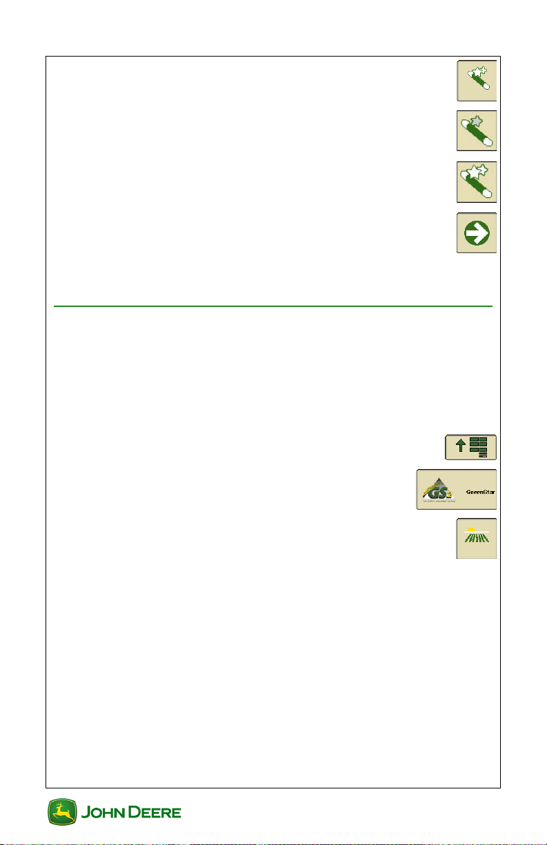
3. Setup Wizard ..................................................................
a. Basic Setup - For quick Straight Track guidance
setup.
b. Standard Setup - For Equipment, Documentation,
fields, and Guidance setup.
4. Fill out the necessary items on each setup page and
press Next to continue.
NOTE: All items must be filled out on each page before the Next
button will appear.
Change Field Name
Several types of setup data are tied to Field Names including Guidance
lines and maps.
NOTE: Field Names can only be edited or deleted indivdually using apex
or another type of desktop software. To delete all data and setup
infromation in the display, Backup data to a USB and select that option.
1. Menu ............................................................................
2. GreenStar ..............................................................
3. Quick Change Field ......................................................
4. Select or create a new Client, Farm, and Field name.
NOTE: The Client is the land owner in many cases.
GS2 1800 Display
3
GS2 1800 Display
Page 18
User Guide GreenStar General
User Guide
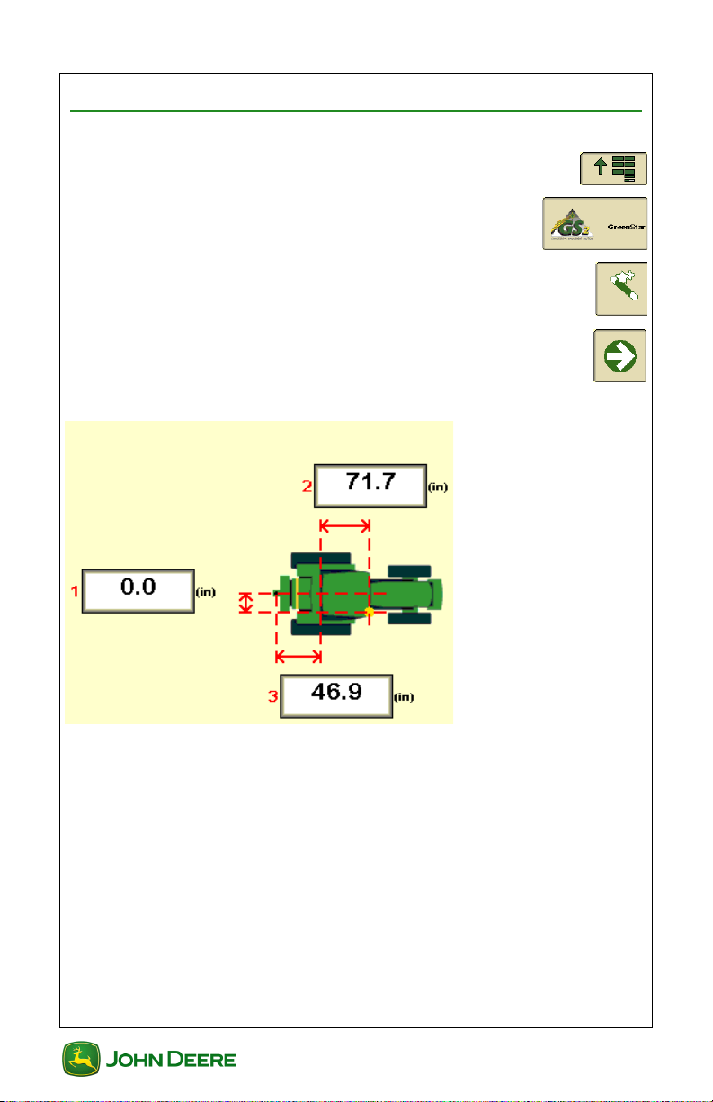
Machine Setup
Machine Offsets
1. Menu ............................................................................
2. GreenStar ..............................................................
3. Setup Wizard ..................................................................
4. Next ................................................................................
1- Lateral distance from the center point of the machine to the center of the GPS receiver.
2- In-line distance from the non-steering axle to the center of the GPS Receiver.
3- In-line distance from the non-steering axle to the connection (or pivot) point.
Non-Steering Axle:
•Rear Axle
○ Row Crop Tractor (Wheel)
○ Self-Propelled Sprayer
○ Track Tractor
•Front Axle
○ Four Wheel Drive
GS2 1800 Display
4
GS2 1800 Display
Page 19

User Guide GreenStar General
User Guide
○ Combine
○ Self-Propelled Forage Harvester
Offset toggles reciever to side other side of implement.
Axle toggles non-steering axle to front.
Connection Type Examples
Rear Rigid 3-pt Front Rigid 3-pt
Rear Pivot 2-pt Rear Pivot Drawbar
Rear Pivot Wagon-Hitch
5
GS2 1800 Display
GS2 1800 Display
Page 20

User Guide GreenStar General
User Guide
Implement Setup
Implement Offsets
NOTE: Grayed out settings were automatically detected from the
implement controller. They can be changed in the implement controller
setup (e.g. SeedStar, SprayStar). The display may need to be restarted
for those changes to take effect.
NOTE: Implement settings can be recalled by selecting the Implement
Name that was set when settings were entered.
1. Menu ............................................................................
2. GreenStar ..............................................................
3. Setup Wizard ..................................................................
4. Next ................................................................................
5. Enter Offsets
NOTE: Offset toggles implement offset (3) to other side.
GS2 1800 Display
6
GS2 1800 Display
Page 21

User Guide GreenStar General
User Guide
1- In-line distance from the connection (or pivot) point to the first working point of
the implement.
2- In-line distance from the first working point to the second working point. (e.g.
location of seed drop, spray nozzles, cutter bar).
NOTE: 1+2 = The point where map recording happens and where Swatch
Control Pro turns sections on/off.
3- Lateral distance from the center point of the machine to the center point of the
working width of the implement.
NOTE: This measurment (3) is used for map recording on implement
configurations that are offset to one side.
4- In-line distance from the connection (or pivot) point to control point of the
implement.
NOTE: This measurment (4) is important for modeling the position of the
implement, particularly on curves.
Connection (or Pivot) Point- The point where the implement connects to the
machine or the pivot point between the implement and machine depending on
Connection Type. It should be the same point used in measurement C of machine
setup.
Control Point- Point the that the implement rotates around; usually the center of
all transport wheels. This point is at the connection point for 3-point mounted
implements.
6. Enter Widths
GS2 1800 Display
7
GS2 1800 Display
Page 22

User Guide GreenStar General
User Guide
Implement Width (Working Width)- The actual width of planter, sprayer, or
harvester.
Coverage Recording Source
1. Select Coverage Recording
source
2. Next ................................................................................
GS2 1800 Display
8
GS2 1800 Display
Page 23

User Guide GreenStar General
Transfer
Data
User Guide
Data Management
All settings and recorded data can be transferred to and from a display of
the same model or Apex desktop software. All data and settings are
imported or exported as a Data Profile.
Backup Data from the Display
1. Turn off all types of Recording and stop the vehicle.
2. Insert USB flash drive.
NOTE: The display’s internal memory has 256 MB of capacity for field
data.
3. A “USB Detected” message will appear if the display
recognizes the USB memory device. Read and
Accept.
Troubleshooting Tips!!! Try the other USB port (if equiped) or a
different USB memory device.
NOTE: The USB must be formatted to FAT or FAT32.
4. Menu ............................................................................
5. GreenStar ..............................................................
6. Read and Accept any alert messages .........................
7. Transfer Data .........................................................
8. Backup Data ................................................
9. Select or create a Profile name where the
data will be stored on the USB.
IMPORTANT: Backup of data to an existing Profile will overwrite all data and settings in that Profile.
10. Check the box if you would like to Delete All Data and Setup
Information from the internal Memory. This clears the internal
GS2 1800 Display
9
GS2 1800 Display
Page 24

User Guide GreenStar General
Delete files from internal memory after backup
is complete
Transfer
Data
User Guide
memory and will reset the Setup Information to factory defaults
after backup is complete.
11. A green status bar will appear while data is transferring. When
finished, a “Data Transfer is Complete” message will appear.
IMPORTANT: To prevent data loss, do NOT remove the USB or
crank the engine during data transfer.
Importing Data to the Display
1. Turn off all types of Recording and stop the vehicle.
2. Insert USB memory device with a Data Profile from a display of
the same model or Apex.
3. A “USB Detected” message will appear if the display
recognizes the USB memory device. Read and
Accept.
Troubleshooting Tips!!! Try the other USB port (if equiped) or a
different USB memory device.
NOTE: The USB must be formatted to FAT or FAT32.
4. Menu ............................................................................
5. GreenStar ..............................................................
6. Read and Accept any alert messages .........................
7. Transfer Data .........................................................
8. Import Data ..................................................
9. Select Data Profile to be imported ................
IMPORTANT: The imported Profile will overwrite all data and
setup information in the display.
GS2 1800 Display
10
GS2 1800 Display
Page 25

User Guide GreenStar General
Yes
No
Recording
User Guide
10. A “Import File” message will appear. Read and
select Yes to import the file or select No to decline the
import file.
11. A green status bar will appear while data is
transferring. When finished, a “Data Transfer is Complete”
message will appear.
IMPORTANT: To prevent data loss, do NOT remove the USB or
crank the engine during data transfer.
View Memory Remaining
1. Menu ............................................................................
2. GreenStar ..............................................................
3. GS2 ..................................................................................
4. Diagnostic .....................................................................
5. Select Recording from the list .....................
6. View “Memory Space Left (MB)”. Status bar will indicate the
amount of used internal memory space.
Transferring Data between Two Displays
Apex or a compatible 3rd party desktop software is required for
transferring data and setup information between different John Deere
Display models (i.e. Original GreenStar Display, GS2 1800, GS2 2600,
GS3 2630, and GS3 CommandCenter). Due to different file versions, data
will not load when transferred directly between different models.
Follow the steps for backup and import to transfer setup information and
data between two displays of the same model. The data will NOT be
merged. All setup information and data on the second display will be
replaced. Think of the transfer as moving a CF card from one GS2 2600
to another.
GS2 1800 Display
11
GS2 1800 Display
Page 26

User Guide GreenStar General
Cleanup
Data Cleanup
Select the type of data you wish to delete
Client:
Field:
Farm:
Delete Selected
Data
User Guide
Data Cleanup
Data cleanup removes Clients, Farms, or Field Names from the display's
internal memory.
1. Menu ............................................................................
2. GreenStar ..............................................................
3. GS2 ..................................................................................
4. Settings ..........................................................................
5. Data Cleanup ..................................................................
6. Select the type of data to delete:
7. Select items to delete:
NOTE: If an item has been selected in the setup wizard it will be grayed
out and will not be able to delete it.
NOTE: To select a checkbox, scroll and select the entire checkbox list
area. Select the desired checkbox. To exit the checkbox list, press the
Cancel "X" button on the display.
8. Delete Selected Data ..........................................
12
GS2 1800 Display
GS2 1800 Display
Page 27

User Guide GreenStar General
Yes
User Guide
Record a Boundary
Field boundaries are useful for calculating field area or when using Swath
Control. The Setup Wizard must be completed before creating a
boundary.
1. Menu ............................................................................
2. GreenStar ..............................................................
3. Field ................................................................................
4. Boundary ........................................................................
5. Choose Exterior or Internal Boundary ........
NOTE: An Exterior Boundary must be created before an Internal
Boundary can be created. An Internal Boundary will require a Name.
6. Enter Boundary Offset ...........................
7. Select which side to apply the Offset ...............................
8. Next ................................................................................
9. Record the boundary ......................................................
10. Pause boundary recording .............................................
11. Stop boundary recording ................................................
12. Select Yes to complete the boundary .........................
NOTE: When Stop Boundary Recording is selected, the beginning and
end of the boundary line will be connected with a straight boundary line.
GS2 1800 Display
13
GS2 1800 Display
Page 28

User Guide GreenStar General
User Guide
NOTES
14
GS2 1800 Display
GS2 1800 Display
Page 29

User Guide Guidance
User Guide
Section Contents
GETTING STARTED............................................................ 2
Accessing Guidance Functions ............................................................ 2
Requirements for Guidance Operation ................................................. 2
AutoTrac Status Pie.............................................................................. 3
CHOOSE TRACKING MODE .............................................. 4
Straight Track Mode ............................................................................. 4
AB Curve Mode .................................................................................... 4
Adaptive Curve Mode ........................................................................... 4
GUIDANCE TRACK SETUP ................................................ 6
Step 1) Enter Track Spacing ................................................................ 6
Step 2) Select Tracking Mode and Guidance Track ............................. 6
Step 3) Create a Guidance Track ......................................................... 6
Create AB Straight Track...................................................................... 6
Create an AB Curve Track ................................................................... 8
Create Adaptive Curve Track ............................................................... 8
Create a Circle Track............................................................................ 9
Delete Track ......................................................................................... 9
RUN PAGE......................................................................... 11
GUIDANCE SETTINGS...................................................... 12
Accessing Guidance Settings ............................................................. 12
General Guidance Settings ................................................................ 12
AutoTrac Settings ............................................................................... 12
Advanced AutoTrac Settings (if equipped) ......................................... 13
Curve Track Settings .......................................................................... 13
Lightbar Settings................................................................................. 14
Shift Track Settings ............................................................................ 14
GS2 1800 Display
1
GS2 1800 Display
Page 30

User Guide Guidance
User Guide
Getting Started
This section includes basic functions for using Guidance.
Accessing Guidance Functions
1. Menu ............................................................................
2. GreenStar ..............................................................
3. Guidance .......................................................................
NOTE: The Guidance button is also available on the Run (map) page.
Requirements for Guidance Operation
The following items are required for guidance to function:
• AB Lines
• GPS Signal
• Tracking Mode
• Track Spacing
The following items are optional when operating guidance:
• Client, Farm, and Field
• Coverage Map
• Field Boundaries
Read the AutoTrac Status Pie section for AutoTrac require-
ments.
GS2 1800 Display
2
GS2 1800 Display
Page 31

User Guide Guidance
User Guide
AutoTrac Status Pie
The AutoTrac Status Pie indicates what items are remaining to be setup
for AutoTrac to function.
Stage 1: Installed
• SSU is detected
Stage 2: Configured
• Tracking Mode has been selected
• Guidance AB Line has been defined
• AutoTrac Activation detected
• StarFire signal is present
• SSU has no active faults pertaining to the steering
function
• Hydraulic oil warmer than minimum temperature
• Speed is less than maximum
• TCM message is currently available and valid
• In proper operating gear
Stage 3: Enabled
• Select Auto
Stage 4: Activated
•Press Resume Switch on the Machine
GS2 1800 Display
3
GS2 1800 Display
Page 32

User Guide Guidance
User Guide
Choose Tracking Mode
GreenStar guidance has several different tracking modes to suit almost
any field layout and operator preference.
Straight Track Mode
Straight Track mode assists operator in driving straight
parallel paths by using display and audible tones to
alert operator when machine is off track.
AB Curve Mode
AB Curves allows an operator to drive
a curved line in the field with two end
points (beginning and end). The
passes parallel to the track in either
direction will be generated based on
the original driven track. Each pass is
generated from the original driven
pass to ensure that steering errors
are not propagated through the entire
field. The passes are not identical
copies of the original pass. The
curvature of the pass changes to
maintain pass to pass error.
A—Start Recording of AB Curve
B—Stop Recording of AB Curve
C—Paths Generated
Adaptive Curve Mode
Adaptive Curve allows the operator to
record a manually driven path. The
vehicle can be guided along
subsequent passes, based on the
previous recorded pass. The passes
are not identical copies of the original
pass. The curvature of the pass
changes to maintain pass to pass
error. When necessary, the operator
can change the curve path anywhere
in the field by simply steering the
machine off the propagated path.
4
GS2 1800 Display
GS2 1800 Display
Page 33

User Guide Guidance
User Guide
NOTE: The curvature of the path changes as the subsequent paths get
more convex or concave.
GS2 1800 Display
5
GS2 1800 Display
Page 34

User Guide Guidance
User Guide
Guidance Track Setup
Step 1) Enter Track Spacing
Track Spacing is entered as part of the Setup Wizard.
1. GreenStar ..............................................................
2. Spacing ..........................................................................
• Implement Width – used to generate on screen map and for
area calculations.
• Track Spacing – define the desired overlap or skip between
passes
Step 2) Select Tracking Mode and Guidance Track
1. GreenStar ..............................................................
2. Guidance .......................................................................
3. Select desired Tracking Mode ........
4. Select the name of track or create a New
Track. Check the Edit Track box to make
changes to and existing Track.
5. Next ................................................................................
Step 3) Create a Guidance Track
Use the following steps for the appropriate track type.
Create AB Straight Track
There are several ways to create an AB Straight Track. Straight Track
must be selected in the Tracking Mode list on the Guidance page.
GS2 1800 Display
6
GS2 1800 Display
Page 35

User Guide Guidance
User Guide
A + B Method
1. Drive to desired beginning of AB line, Set A ...................
2. Drive toward desired end of AB line, Set B ....................
A + Heading Method
1. Drive to desired beginning of AB line, Set A ...................
2. Set Heading ...................................................................
3. Enter desired Heading to Set B ...............................
Auto B Method
1. Drive to desired beginning of AB line, Set A ...................
2. Drive toward desired end of AB line. Automatically Set
B The B point will automatically set after 49 feet (15
meters).
Lat / Long Method
1. Set A Point Latitude and Longitude .................................
2. Enter coordinates to Set A ...........................
3. Set B Point Latitude and Longitude .................................
4. Enter coordinates to Set B ...........................
GS2 1800 Display
7
GS2 1800 Display
Page 36

User Guide Guidance
User Guide
Lat / Long + Heading Method
1. Set A Point Latitude and Longitude .................................
2. Enter coordinates to Set A ...........................
3. Set Heading ...................................................................
4. Enter desired Heading of B point .....................
Create an AB Curve Track
AB Curves must be selected in the Tracking Mode list on the Guidance
page.
1. Record initial pass ..........................................................
a. Selecting Pause will allow user to pause recording
vehicles path.
b. When recording is un-paused it will connect the two
points into a straight line.
A – Recording Turned ON then PAUSED
B – Bridge segment is generated to connect points
C – Recording UNPAUSED
2. Stop Recording at the end of the desired AB Curve .....
Create Adaptive Curve Track
Adaptive Curves must be selected in the Tracking Mode list on the
Guidance page.
GS2 1800 Display
8
GS2 1800 Display
Page 37

User Guide Guidance
User Guide
1. Record initial pass ...........................................................
a. Selecting Pause will allow user to pause recording
vehicles path.
b. When recording is un-paused it will connect the two
points into a straight line.
2. Stop Recording at the end of the desired Adaptive
Curve.
Create a Circle Track
Drive Circle Method
1. Record initial circle pass ................................................
2. Stop Recording at the end of the circle pass .................
Lat/Lon Method
1. Set Center Point Latitude and Longitude ........................
2. Enter coordinates for Center Point ...............
Delete Track
1. GreenStar ..............................................................
2. Guidance .......................................................................
3. Select Type of Track to delete ...................
GS2 1800 Display
9
GS2 1800 Display
Page 38

User Guide Guidance
Yes
User Guide
4. Select Track name to delete ......................
5. Delete Track ..................................................................
6. Select Yes to delete track ............................................
10
GS2 1800 Display
GS2 1800 Display
Page 39

User Guide Guidance
User Guide
Run Page
• Pass Accuracy
• Variance from “0” shows Off-track Error
• Status Pie .........................................................................
• Steering On/Off Button ..................................................
• GPS Accuracy Indicator ................................................
11
GS2 1800 Display
GS2 1800 Display
Page 40

User Guide Guidance
General
Settings
Turning View
Turn Predictor
AutoTrac Deactivation
Message
Tracking Tones
AutoTrac
Settings
User Guide
Guidance Settings
Accessing Guidance Settings
1. Menu ............................................................................
2. GreenStar ..............................................................
3. GS2 ..................................................................................
4. Settings ..........................................................................
General Guidance Settings
1. General Settings .......................................................
2. Choose selected settings.
3. Next Page ......................................................................
4. Set Tracking Tones ........................................
5. Set Lead Compensation ...................................
6. Accept ..........................................................................
AutoTrac Settings
1. AutoTrac Settings .....................................................
12
GS2 1800 Display
GS2 1800 Display
Page 41

User Guide Guidance
Line Sensitivity
Heading
Line Sensitivity
Tracking
Heading
Lead
Steering
Response Rate
Curve
Sensitivity
Acquire
Sensitivity
Curve
Settings
Smooth Tight Turns ON
User Guide
2. Enter Steering Sensitivity .........................................
3. Accept ..........................................................................
Advanced AutoTrac Settings (if equipped)
Use Advanced AutoTrac Settings to optimize AutoTrac performance.
AutoTrac Advanced settings are only available on some vehicle types.
• Describes each function .....................................................
Curve Track Settings
1. Curve Track Settings ................................................
2. Smooth Tight Turns .........................
13
GS2 1800 Display
GS2 1800 Display
Page 42

User Guide Guidance
Smooth Tight Turns OFF
Smooth Tight Turns ON
Clear
Data
Repeat Mode
Lightbar Settings
Steer Towards Direction
Off-Track Direction
User Guide
3. Select Implement In-Ground Turn Radius ...........
4. Next Page ....................................................................
5. Choose Recording Source ................
a. Clear Adaptive Curve Data
b. When recording a new path, Repeat Mode
should be unchecked or OFF. To follow
existing paths, Repeat Mode should be ON
or checked.
6. Accept ..........................................................................
Lightbar Settings
1. Lightbar Settings ......................................................
2. Select Step Size for distance that each light on
the Lightbar represents.
3. Select how the Lightbar indicates where
to steer when off the track.
4. Accept ..........................................................................
Shift Track Settings
14
GS2 1800 Display
GS2 1800 Display
Page 43

User Guide Guidance
Shift Track
Shifts Off
Small Shifts
Large Shifts
Shift Size
Yes
User Guide
Select Type of Shifts
1. Shift Track Settings ................................................
2. Select type of shifts
3. Accept ..........................................................................
Clear Shifts
1. GreenStar ..............................................................
2. Guidance ........................................................................
3. Clear shifts .....................................................................
4. Select Yes to clear shifts .............................................
GS2 1800 Display
15
GS2 1800 Display
Page 44

User Guide Guidance
User Guide
NOTES
16
GS2 1800 Display
GS2 1800 Display
Page 45

User Guide Performance Monitor
User Guide
Section Contents
MONITOR MACHINE PERFORMANCE.............................. 2
View in Performance Monitor ............................................................... 2
View on Homepages ............................................................................ 2
PERFORMANCE MONITOR SETUP................................... 3
Setup Area Counter.............................................................................. 3
PERFORMANCE MONITOR TOTALS ................................ 4
Acre Counter Manual Start and Stop.................................................... 4
Resetting Performance Monitor Totals ................................................. 4
GS2 1800 Display
1
GS2 1800 Display
Page 46

User Guide Performance Monitor
User Guide
Monitor Machine Performance
Performance Monitor provides productivity information such as vehicle
speeds, acre counters, and fuel efficiency data. The information available
to be displayed depends on the vehicle on which the display is installed.
View in Performance Monitor
1. Menu ............................................................................
2. Performance Monitor ...........................................
3. Performance Information ..............................................
4. Performance Totals .......................................................
NOTE: The Performance Totals page will populate several options such
as travel counters and vehicle information.
View on Homepages
Use Layout Manager to add a Performance Monitor screen for any Home
Page.
GS2 1800 Display
2
GS2 1800 Display
Page 47

User Guide Performance Monitor
AUTO
User Guide
Performance Monitor Setup
Setup Area Counter
1. Menu ............................................................................
2. Performance Monitor ...........................................
3. Settings ..........................................................................
4. Enter Implement Width ...................................
5. Select a control source to start and stop the Area Counter. The
available options depend on the vehicle configuration.
• Implement Whisker Switch .........................................
• Use source from John Deere implement ................
• Manual ....................................................................
• Front Hitch
• Rear Hitch
GS2 1800 Display
3
GS2 1800 Display
Page 48

User Guide Performance Monitor
User Guide
Performance Monitor Totals
Performance Monitor calculates a running total of several values including
acres and distance.
Acre Counter Manual Start and Stop
NOTE: Manually starting and stopping the Area Counter is not necessary
when the Area Counter control source is set to an option other than
Manual.
1. Menu ............................................................................
2. Performance Monitor ...........................................
3. Performance Monitor Main ...........................................
4. Acre Counter Start / Stop ..........................................
ON OFF
Resetting Performance Monitor Totals
1. Menu ............................................................................
2. Performance Monitor ...........................................
3. Totals ..............................................................................
4. Reset Distance ......................................................
5. Reset Average Totals ..................................................
There are two reset buttons on the page. Each is displayed within the
group of values that it resets.
GS2 1800 Display
4
GS2 1800 Display
Page 49

User Guide Swath Control
User Guide
Section Contents
GETTING STARTED............................................................ 2
Turning Swath Control Pro On/Off........................................................ 2
RUN PAGE - SWATH CONTROL........................................ 3
SWATH CONTROL SETTINGS........................................... 4
Turn On/Off Settings............................................................................. 4
Overlap Settings ................................................................................... 4
GS2 1800 Display
1
GS2 1800 Display
Page 50

User Guide Swath Control
User Guide
Getting Started
This section includes basic functions for using Swath Control with product
applications. Use the Setup Wizard to setup the machine and implement
before using Swath Control.
NOTE: Boundaries are not required but may be helpful when using Swath
Control.
Turning Swath Control Pro On/Off
1. Menu ............................................................................
2. GreenStar ..............................................................
3. Select Swath Control On/Off to enable or disable Swath
Control.
GS2 1800 Display
2
GS2 1800 Display
Page 51

User Guide Swath Control
Swath Control Pro Off
User Guide
Run Page - Swath Control
The following information is shown on the Run Page.
Swath Control On/Off enables or disables Swath
Control.
Section Status Bar displays the system status
• Swath Control Off
• Swath Control On - Air Cart example
NOTE: Green bar at bottom - Swath Control Enabled and section On.
NOTE: Tank bar is black - Tank is On.
NOTE: Tank bar is clear - Tank is Off.
• Swath Control On - Product Application example
NOTE: Green or blue triangle - Section status is On.
NOTE: A clear triangle - Section status is Off.
GS2 1800 Display
3
GS2 1800 Display
Page 52

User Guide Swath Control
User Guide
Swath Control Settings
Settings are used to fine tune Swath Control for optimal performance.
1. GreenStar ..............................................................
2. GS2 ..................................................................................
3. Settings ..........................................................................
4. Swath Control Settings ................................................
Turn On/Off Settings
The operator can adjust the Turn on and Turn off settings to fit a specific
machine. The Turn on and Turn off settings are to compensate for
average physical machine reaction time (Electrical & Mechanical) for
applying product. Refer to the Operators Manual for additional
information.
1. Set the Turn on Time ........................................
NOTE: Turn on Time compensates for the time delay between the system
turning on and the product being applied in the field.
2. Set the Turn off Time .........................................
NOTE: Turn off Time compensates for the time delay between the system
turning off and when the product stops being applied in the field.
NOTE: Implement Offset 1 + Implement Offset 2 is the point that Swath
Control uses to turn sections on or off.
Overlap Settings
The system can be set to minimize overlap (0%), minimize skips (100%),
or apply a certain percentage of overlap from 0% to 100%.
GS2 1800 Display
4
GS2 1800 Display
Page 53

User Guide Swath Control
Exterior Boundaries
Amount to Overlap
Interior Boundaries
Amount to Overlap
Previous Coverage
Amount to Overlap
User Guide
1. Set the percentage of overlap
GS2 1800 Display
5
GS2 1800 Display
Page 54

User Guide Swath Control
User Guide
NOTES
GS2 1800 Display
6
GS2 1800 Display
Page 55

User Guide Documentation Basics
User Guide
Section Contents
SECTION CONTENTS ......................................................... 1
GETTING STARTED............................................................ 2
Accessing Documentation Basics ........................................................ 2
DOCUMENTATION BASICS SETUP .................................. 3
Standard Setup Mode........................................................................... 3
DOCUMENTATION BASICS TOTALS................................ 3
Viewing Totals ...................................................................................... 3
GS2 1800 Display
1
GS2 1800 Display
Page 56

User Guide Documentation Basics
User Guide
Getting Started
This section includes basic functions for using Documentation Basics.
Use the Standard Setup Mode in the Setup Wizard to setup
Documentation Basics.
Accessing Documentation Basics
1. Menu ............................................................................
2. GreenStar ..............................................................
3. Setup Wizard ..................................................................
4. Standard Setup Mode ....................................................
GS2 1800 Display
2
GS2 1800 Display
Page 57

User Guide Documentation Basics
User Guide
Documentation Basics Setup
Standard Setup Mode
1. GreenStar ..............................................................
2. Setup Wizard ..................................................................
3. Standard Setup .............................................................
4. Select Machine ................................
5. Select Implement .............................
6. Select Task ...................................................
7. Select Crop Type or Product Type
8. Select Client .................................................
9. Select Farm ..................................................
10. Select Field ..................................................
11. Tracking Mode (optional) .............................
Documentation Basics Totals
Viewing Totals
1. Menu ............................................................................
2. GreenStar ..............................................................
GS2 1800 Display
3
GS2 1800 Display
Page 58

User Guide Documentation Basics
User Guide
3. GS2 ..................................................................................
4. Documentation ..............................................................
5.
Totals ..............................................................................
Reports
A PDF report of the recorded data is created when data is transferred
from the display to the USB flash drive.
Reports will be found on the USB drive on the following path:
<USB-Stick>: \ GS2_1800 \ profile name of backup \ Reporting \
<report>.pdf \ <report>.csv
NOTE: Documentation Basics requires an activation on the display for it
to be an option.
NOTE: John Deere Documentation Basics will only support implements
that are performing one operation only. See operators manual for more
details.
GS2 1800 Display
4
GS2 1800 Display
 Loading...