

Page 1

73 Series Spectrophotometer
061 672 REV B/08-14
Accessory fitting and operation manual
Page 2

2
Page 3

3
Safety
Please read this information carefully prior to installing or using this equipment.
1. The unit described in this manual is designed be operated only by trained personnel. Any
adjustments, maintenance and repair must be carried out as defined in this manual, by a
person qualified to be aware of the hazards involved.
2. It is essential that both operating and service personnel employ a safe system of work, in
addition to the detailed instructions specified in this manual.
3. Other than for those items defined in the maintenance procedures herein there are no user
serviceable items in this instrument. Removal of covers and attempted adjustment or
service by unqualified personnel will invalidate the warranty and may incur additional
charges for repair.
4. References should always be made to the Health and Safety data supplied with any
chemicals used. Generally accepted laboratory procedures for safe handling of chemicals
should be employed.
5. If it is suspected that safety protection has been impaired in any way, the unit must be made
inoperative and secured against any intended operation. The fault condition should
immediately be reported to the appropriate servicing authority.
Merci de lire attentivement ces informations avant d'installer ou d'utiliser cet appareil.
1. L'appareil décrit dans ce manuel est conçu pour être utilisé uniquement par des personnes
formées. Tout réglage, maintenance ou réparation doit être effectué comme décrit dans ce
manuel, par une personne qualifiée consciente des risques encourus.
2. Il est essentiel que les personnes utilisant et intervenant sur cet appareil respectent les
règles de sécurité de travail, en plus des instructions détaillées précisées dans ce manuel.
3. En-dehors des éléments décrits dans les procédures de maintenance ci-incluses, cet appareil
ne contient aucun élément réparable par l'utilisateur. L'enlèvement des capots et les
tentatives de réglage ou de réparation par des personnes non qualifiées invalide toute
garantie et entraîne un risque de frais de réparation supplémentaires.
4. Toujours se référer aux fiches techniques de santé et de sécurité accompagnant tout produit
chimique utilisé. Respecter les procédures de laboratoire généralement acceptées pour la
manipulation en toute sécurité des produits chimiques.
5. Si l'utilisateur suspecte qu'un problème quelconque puisse mettre en cause la sécurité,
l’appareil doit être rendu inopérant en empêchant son utilisation. Communiquer la
défaillance constatée au service de maintenance compétent.
Page 4

4
Bitte lesen Sie diese Hinweise vor Installation oder Gebrauch dieser Ausrüstung sorgfältig durch.
1. Das in diesem Handbuch beschriebene Gerät darf nur von geschultem Personal bedient
werden. Alle Anpassungen, Wartungsarbeiten und Reparaturen müssen entsprechend der
Vorgaben in diesem Handbuch und von einer kompetenten Person, die mit den damit
verbundenen Gefahren vertraut ist, durchgeführt werden.
2. Es ist wichtig, dass sowohl das Bedienungs- als auch das Service-Personal zusätzlich zu den
detaillierten Anweisungen in diesem Handbuch ein sicheres Arbeitssystem einsetzen.
3. Mit Ausnahme der Teile, deren Wartungsverfahren in diesem Handbuch beschrieben sind,
enthält dieses Gerät keine weiteren Teile, die vom Benutzer gewartet werden können. Das
Entfernen von Abdeckungen und Versuche von hierfür unqualifiziertem Personal,
Anpassungen oder Wartungsarbeiten durchzuführen, haben zur Folge, dass die Garantie
verfällt und können zusätzliche Reparaturkosten auslösen.
4. Es ist jederzeit auf die sicherheitsrelevanten Daten sämtlicher verwendeter Chemikalien
Bezug zu nehmen. Allgemein anerkannte Labormethoden zum sicheren Umgang mit
Chemikalien sollten eingesetzt werden.
5. Besteht der Verdacht, dass die Sicherheitsvorrichtungen in irgendeiner Weise beschädigt
wurden, muss das Gerät außer Betrieb genommen und gegen weiteren Gebrauch gesichert
werden. Die Störung sollte der zuständigen Serviceeinrichtung unverzüglich gemeldet
werden.
Leggere attentamente queste istruzioni prima di installare o utilizzare il dispositivo.
1. L'unità descritta nel presente manuale è stata realizzata per essere utilizzata solo da
personale che ha ricevuto l'apposita formazione. Qualsiasi operazione di regolazione,
manutenzione e riparazione deve essere effettuata sulla base di quanto indicato nel
presente manuale da personale qualificato consapevole dei rischi connessi.
2. È fondamentale che il personale operativo e il personale addetto alla manutenzione
utilizzino un sistema di lavoro sicuro, oltre a seguire le istruzioni specificate nel presente
manuale.
3. Oltre a quelli indicati nelle procedure di manutenzione, all'interno di questo dispositivo non
sono presenti altri elementi sui quali è possibile effettuare interventi. La rimozione delle
protezioni e qualsiasi tentativo di regolazione o di manutenzione posto in essere da
personale non qualificato invaliderà la garanzia. In questi casi, sarà necessario pagare un
importo per le riparazioni effettuate.
4. È sempre necessario fare riferimento ai dati sulla salute e sulla sicurezza forniti con le
sostanze chimiche utilizzate. Adottare le procedure di laboratorio generalmente accettate
per la gestione delle sostanze chimiche.
5. Nel caso in cui si sospetti che la salute possa essere pregiudicata in qualsiasi modo,
disattivare l'unità per renderla inutilizzabile. Qualsiasi condizione di errore deve essere
immediatamente segnalata al responsabile per la manutenzione.
Page 5

5
Lea esta información atentamente antes de instalar o utilizar este equipo.
1. La unidad descrita en este manual está diseñada para que solamente la utilice personal con
formación. Cualquier operación de ajuste, mantenimiento y reparación debe llevarse a cabo
del modo indicado en este manual y debe realizarla una persona cualificada que sea
consciente de los peligros que implica.
2. Es fundamental que tanto los operarios como el personal de servicio utilicen un sistema de
trabajo seguro, así como las instrucciones detalladas que se especifican en este manual.
3. Cualquier elemento que no se encuentre entre los definidos en los procedimientos de
mantenimiento aquí descritos no podrá utilizarse en este instrumento. La extracción de las
tapas y los intentos de ajuste o reparación por parte de personal no cualificado invalidarán
la garantía y pueden incurrir en cargos adicionales por reparación.
4. Siempre deberían consultarse los datos sobre Salud y Seguridad que se suministran con
cualquier producto químico que se utilice. Es necesario llevar a cabo los procedimientos de
laboratorio de aceptación generalizada para la manipulación segura de productos químicos.
5. Si existe la sospecha de que las medidas protectoras de seguridad han quedado dañadas en
cualquier modo, la unidad debe inutilizarse y protegerse contra toda operación que se
intente llevar a cabo. El estado de fallo debe comunicarse inmediatamente a la autoridad de
servicio de mantenimiento y reparación pertinente.
Page 6

6
Contents
SECTION 1 – Accessories and Spare Parts ........................................................................ 7
1.1 OPTIONAL ACCESSORIES ..................................................................................................................... 7
1.2 CONNECTING THE ACCESSORIES ........................................................................................................ 7
1.2.1 INTERNAL PRINTER ............................................................................................................................. 7
1.2.2 PASSIVE ACCESSORIES ........................................................................................................................ 8
1.2.2.1 Water-heated cuvette holder ............................................................................................................. 9
1.2.3 ACTIVE ACCESSORIES ........................................................................................................................ 11
1.2.3.1 Automatic 8 cell turret ..................................................................................................................... 12
1.2.3.2 Peltier ............................................................................................................................................... 12
1.2.3.3 Sipper pump ..................................................................................................................................... 13
1.2.3.4 Combined sipper Peltier pump ......................................................................................................... 16
1.3 USING THE ACCESSORIES .................................................................................................................. 16
1.3.1 Automatic 8 cell turret ..................................................................................................................... 16
1.3.1.1 Automatic 8 cell turret – supporting creation of a standard curve in quantitation ......................... 17
1.3.2 Peltier ............................................................................................................................................... 17
1.3.3 Sipper pump ..................................................................................................................................... 18
1.3.3.1 Manual Sipper Pump Settings .......................................................................................................... 18
1.3.3.2 Timed Sipper Pump Settings ............................................................................................................. 19
1.3.4 Combined sipper Peltier pump ......................................................................................................... 22
1.4 SPARES .............................................................................................................................................. 22
Page 7
7
SECTION 1 – Accessories and Spare Parts
Part Code
Description of Accessory
660 101
Internal printer
735 401
Automatic 8 cell turret
735 201
Sipper pump
735 301
Peltier
735 701
Combined sipper Peltier pump
735 801
10x10mm path length cuvette holder
735 901
16/24mm test tube holder
736 001
10x100mm path length cuvette holder
736 101
10x10mm path length micro-cuvette holder
736 201
Water heated 10x10 single cell holder
035 088
Visible calibration set
035 091
UV/Visible calibration set
060 422
Molded cuvette rack for 16 10x10mm cuvettes
735 001
Dust cover
019 146
4GB USB memory sticks for external memory
037 551
RS232 to USB converter for use with computer without a serial port
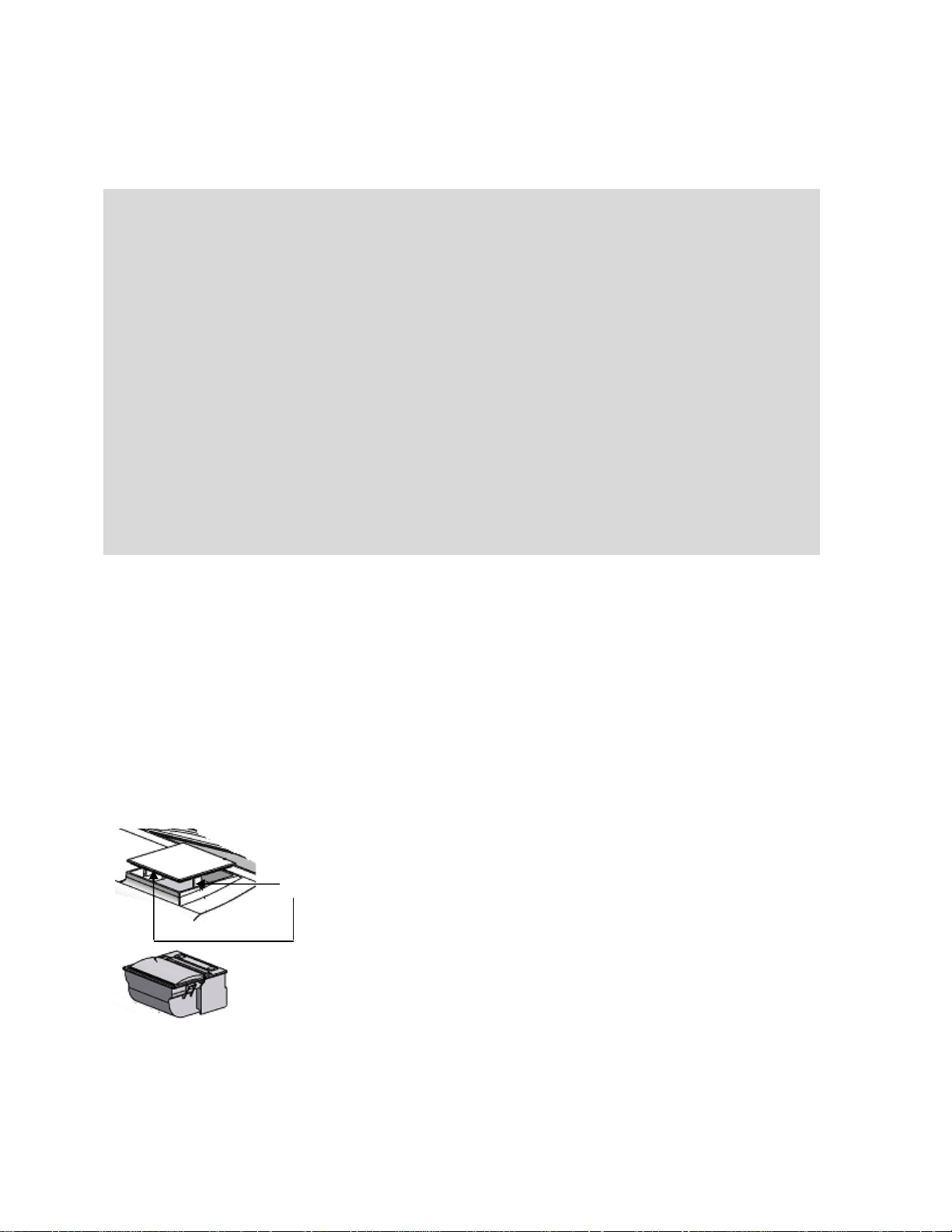
Use a small screw driver to lift the blanking panel on the top of
the instrument. Squeeze the two clips in order to remove the
blanking panel. Disconnect the printer wires which are secured
to the underside of the blanking plate.
Unpack the printer from the packaging. Turn the printer upside
down and connect the printer wires by clipping into the
connector on the printer.
Clips
1.1 OPTIONAL ACCESSORIES
1.2 CONNECTING THE ACCESSORIES
There are two types of accessories which can be fitted in the sample chamber – passive or active
accessories. The range of passive accessories includes 10 x 10mm single cuvette holders, single
water heated cuvette holders, adjustable path length (10 to 100 mm) cuvette holders, test tube
holders, boiling tube holders and micro-cuvette holders. The range of active accessories includes an
automated 8 cell changer, sipper pump, Peltier and combined Peltier sipper pump. The instrument
must be turned off before any accessories are fitted.
1.2.1 INTERNAL PRINTER
Page 8
8
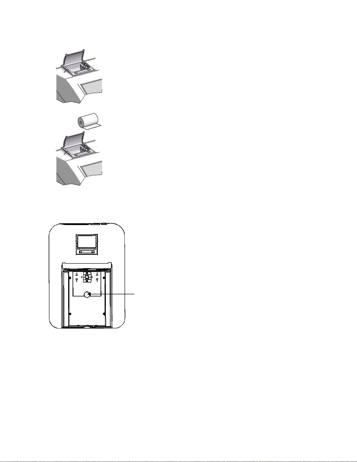
Squeeze the grey plastic clips together so that the printer top
opens. Slot the printer into the top of the instrument and push
down until it fits flush to all four sides.
Insert the paper roll into the printer – ensuring that there is
some paper sticking out of the printer before clicking the grey
plastic back into place. Switch the instrument on. The power and
error lights on the printer will flash. Once the instrument power
on tests are complete press the feed button to check that the
paper is fed correctly.
Unscrew the thumb screw to undo the passive
accessory. Lift out the passive accessory. To fit a
different passive accessory simply place the
accessory in the correct orientation, align the
thumb screw and tighten to fix in place.
To replace the passive accessory with an active
accessory refer to section 11.2.3.
Thumb
screw
1.2.2 PASSIVE ACCESSORIES
Page 9

9
1.2.2.1 Water-heated cuvette holder
The water heated cuvette holder is supplied with an additional front panel which also needs to be
fitted.
The water heated cuvette holder is already fitted to
a base plate so the base plate in the instrument
must be removed before installation. Unscrew
screws 1 to 4 and lift out the metal base plate.
For this accessory as well as removing the passive
accessory base plate, the front panel of the
instrument must also be removed. Loosen screws 5
and 6 until the front panel can be lifted out in the
forwards direction.
2
4 3 1
5
6
Page 10

10
Once the base plate and front panel have
been removed insert the water-heated
cuvette holder into the chamber, ensuring
the base plate rests flat in the unit. Replace
the screws 1 to 4, securing the accessory in
place.
Fit the custom front panel to the unit
ensuring the metal pipes on the accessory
are aligned and fed through the two holes in
the front panel. The metal pipes should
protrude from the outer casing. Secure the
custom accessory front plate to the unit with
screws 5 and 6.
Page 11

11
From the rubber tubing supplied, cut two
shorter lengths of tubing and use these to
connect the internal metal pipes of the cell
block (7) to the internal metal pipes on the
outer casing (8).
Using two separate pieces of rubber tubing
connect the two external metal tubes (9) to
an external water bath and pump. Ensure
that the water is pumped in through the left
hand side of the cell block and out through
the right hand side of the cell block.
All tubing must be kept as short as possible
and the tubing must not be allowed to
obstruct the ligth path.
Unscrew the thumb screw to undo the passive
accessory. Lift out the passive accessory. To fit
an active accessory unscrew screws 1 to 4 and
lift out the metal base plate.
This will expose the bottom of the sample
chamber with the power supply connection
needed to operate the active accessories.
IN OUT
1.2.3 ACTIVE ACCESSORIES
Page 12

12
1.2.3.1 Automatic 8 cell turret
Take the 8 cell turret base plate. Connect the
power supply in the bottom of the sample
chamber to the connector on the underside of
the base plate. Place the base plate in the
sample chamber. Replace screws 1 to 4.
Take the 8 cell carousel and place on top of the
motor, taking care to align the three ball
bearings with the grooves on the motor shaft.
Gently push the carousel down onto the motor
shaft until it is located into place. Gently rotate
the carousel until there is some resistance. The
carousel is now in the correct position.
If the fitting is too tight use a small screw driver
to loosen the ball bearings before pushing the
carousel down onto the shaft.
For this accessory as well as removing the
passive accessory base plate, the front panel of
the instrument must also be removed. Loosen
screws 5 and 6 until the front panel can be lifted
out in the forwards direction.
5
6
1.2.3.2 Peltier
Page 13

13
Take the Peltier base plate. Connect the power
supply in the bottom of the sample chamber to
the connector on the underside of the base
plate. Place the base plate in the sample
chamber. Replace screws 1 to 4. Take the Peltier
front panel and slot into place before
retightening screws 5 and 6.
When the accessory is fitted the instrument will
look like this.
For this accessory as well as removing the
passive accessory base plate, the front panel
of the instrument must also be removed.
Loosen screws 5 and 6 until the front panel
can be lifted out in the forwards direction.
5
6
1.2.3.3 Sipper pump
Page 14

14
Take the sipper base plate. Connect the power
supply in the bottom of the sample chamber
to the connector on the underside of the base
plate. Place the base plate in the sample
chamber. Replace screws 1 to 4. Take the
sipper Peltier front panel and slot into place
before retightening screws 5 and 6.
The tubing should be connected depending on
the function that the sipper pump is going to
perform. All tubing must be kept as short as
possible and the tubing must not be allowed
to obstruct the ligth path.
For sipping:
1. Connect the sipper pump tubing to the
outlet port on the flow-through cuvette.
2. Secure the tubing using the clip on the
righthand side of the pump head.
3. Ease the tubing round the rollers by
carefully rotating them clockwise, by hand.
Clamp the tubing into the clip on the left hand
side of the motor.
4. Once secured, ensure the tubing is routed into the two retaining clips located on the base plate at
the side of the pump head.
5. Cut the tubing at the point where it fits comfortably onto the left hand tube located on the inside
of the front bulk head.
6. Connect a suitable length of this tubing to the external waste pipe.
7. Cut a small length of the sipper pump tube and push this over one end of the capillary tube.
Bi directional flow A
(sipping)
Bi directional flow B
(pumping)
Continuous flow
Page 15

15
Connect this to the inlet port of the flow-through cuvette.
8. Route the tube into the two retaining clips located on the base plate at the side of the pump
head.
9. Fit the sipper probe and secure using the thumbscrew. Feed the capillary tubing through the tube
and up through the sipper probe, allowing sufficient length for it to pass into a suitable receptacle.
For pumping:
1. Cut two pieces of sipper pump tubing
approximately 300mm in length. Take one
length of tubing and fit this to the pump head,
as shown, securing the tubing using the clip on
the right hand side of the pump head.
2. Ease the tubing round the rollers carefully
rotating them clockwise, by hand. Clamp the
tubing into the clip on the left hand side of the
motor.
3. Fit the other end onto the inlet port on the
flow-through cuvette.
4. Fit the second 300mm length of tubing to the outlet port of the flow-through cuvette. Once
secured, ensure the tubing is routed into the two retaining clips located on the base plate at the side
of the pump head.
5. Fit the other end of the tubing onto the outlet port, located on the inside of the front bulkhead.
6. Connect a suitable length of sipper pump tubing to the external outlet port.
7. Insert one end of the capillary tube into the sipper pump tubing, as shown.
8. Feed the other end through the inlet port located on the inside of the bulkhead.
9. Fit the sipper probe and secure using the thumbscrew.
10. Carefully feed the tubing through the sipper probe, allowing sufficient length for it to pass into a
suitable receptacle.
When the sipper accessory has been fitted and
the tubing has been connected the instrument
will look like this.
Page 16

16
1.2.3.4 Combined sipper Peltier pump
Refer to section 11.2.3.3 for more details.
When the automatic 8 cell turret is in use the 8 cell
turret icon is displayed in the bottom right hand corner
of the screen. The current cell position is displayed
adjacent to the 8 cell turret icon. The 0 position should
always be used for the zero calibration sample.
To perform measurements using the automatic 8 cell turret, insert the cuvettes containing the
samples into turret positions 1 to 7. Insert the cuvette containing the blank solution into turret
position 0. Enter the required measurement mode and set up the required measurement
parameters. Press the key below the calibrate to zero icon. The instrument will automatically move
the turret around to position zero to perform the measurement. Once the calibration is complete
the measure sample icon will appear and the turret will return to its original starting position.
Press the key below the 8 cell turret icon to highlight
the icon and the two arrow icons above. Press the keys
adjacent to the arrow icons to increase or decrease
the current cell position of the turret, until the
required sample position has been selected. Press the
key below the measure sample icon. The instrument
will
perform a reading and display the result on the screen. To measure the next sample select the next
turret position and press the key below the measure sample icon. Repeat this process until all the
samples have been measured. To adjust the wavelength press the key below the 8 cell turret icon
and use the arrow icons to adjust the wavelength.
1.3 USING THE ACCESSORIES
1.3.1 Automatic 8 cell turret
Page 17

17
1.3.1.1 Automatic 8 cell turret – supporting creation of a standard curve in quantitation
The 8 cell turret can be used to support creation of a new standard curve in the quantitation
measurement mode. Refer to section 8.2.3.1 for more details.
When the standard measurement screen is open the 8
cell turret icon will be displayed in the bottom left
hand corner of the screen. The current cell position is
displayed adjacent to the 8 cell turret icon. The 0
position should always be used for the zero calibration
sample.
To measure the standards using the automatic 8 cell turret, insert the cuvettes containing the
standards into turret positions 1 to 6 (depending on how many standards needed). Insert the
cuvette containing the blank solution into turret position 0. Press the key adjacent to the tick icon to
perform an initial calibration to zero absorbance.
Use the keys adjacent to the arrow icons to increase the turret position, until the required standard
position has been selected. Press the key adjacent to the tick icon to measure the standard. The
standard concentration and photometric value will then be displayed. The standard can be remeasured by pressing the key adjacent to the back icon.
To measure the next standard select the next turret position and press the key adjacent to tick icon.
Repeat this process until all the standards have been measured.
When the Peltier is in use the Peltier icon is displayed
in the bottom right hand corner of the screen. The
current temperature is displayed above the set point
temperature adjacent to the Peltier icon. An arrow
icon is displayed above or below the Peltier icon
depending on if the current temperature is above or
below the set
temperature. To adjust the set point temperature hold the key below the Peltier icon for 2 seconds.
This opens the Peltier settings screen. Use the keys at
the bottom of the screen to select the digit to be
changed and use the arrow icons to increase or
decrease the number. The temperature can be set in
°C or °F by pressing the key adjacent to the °C icon.
1.3.2 Peltier
Page 18

18
Repeat presses will cycle between °C and °F. Once the
required temperature has been selected press the key
adjacent to the tick icon to save and return to the
operating menu. The Peltier will begin to heat or cool
depending on the current temperature.
When the sipper is in use the sipper pump icon is
displayed in the bottom right hand corner of the
screen. The sipper pump can operate in manual or
timed mode, depending on the option selected in
sipper pump settings. If the manual mode is selected
an arrow icon indicating pump direction will be
displayed below the sipper pump icon.
If the time mode is selected a clock icon will be
displayed adjacent to the sipper pump icon.
To open the sipper pump settings hold the key below
the sipper pump icon for 2 seconds.
To operate the sipper pump in manual mode press the
key adjacent to the manual sipper icon. Select the
preferred pump direction by pressing the key below
the forwards or backwards arrow. Press the key
adjacent to the tick icon to save and return to the
operating menu.
To perform a measurement place the sipper tubing
into the sample and press the key below the sipper
pump icon.
1.3.3 Sipper pump
1.3.3.1 Manual Sipper Pump Settings
Page 19

19
Confirmation will be needed to start the sipper pump.
Press the key adjacent to the tick icon to confirm and
start the sipper pump. Press the key adjacent to the
cross icon to cancel and return to the operating menu.
To stop the sipper pump press the key adjacent to the
stop icon. Ensure that the flow through cuvette
contains enough sample before pressing the key below
the measure sample icon.
To operate the sipper pump in timed mode press the
key adjacent to the timed sipper pump icon.
Press the key below the calibrate timed sipper icon.
Select the required pump direction by pressing the key
below the forwards or backwards arrow. Press the key
adjacent to the tick icon to continue to the next stage
of the calibration sequence.
Insert the inlet tubing into the sample container and
press the key adjacent to the single greater than icon.
The sipper pump will start and the sample will be
pumped through the tubing to the flow through
cuvette. It is possible to skip this setup stage by
pressing the key adjacent to the double greater than
icon.
1.3.3.2 Timed Sipper Pump Settings
Page 20

20
Once the cuvette is full press the key adjacent to the
stop icon to stop the sipper pump. The time taken for
sample uptake is recorded.
To fine tune the amount of sample uptake press the
key below the plus or minus icon to increase or
decrease the amount of sample taken up. The
recorded time will be adjusted accordingly. Once the
fine tuning is complete, or if none is required, press
the key adjacent to the tick icon to move to the next
stage of the calibration sequence.
This stage allows an air gap to be added to the
calibration sequence. If an air gap is not required press
the key below the 001 icon to set the air gap to one. If
a previously programmed air gap is to be used press
the key adjacent to the double greater than icon to
skip this stage and retain the current air gap time.
To program an air gap remove the inlet tubing from the sample container and press the key adjacent
to the single greater than icon. The sipper pump will start and air will be pumped through the tubing
to the flow through cell.
Once the required amount of air has been taken up
press the key adjacent to the stop icon. The time taken
for air uptake is recorded.
To fine tune the amount of air uptake press the key
below the plus or minus icon to increase or decrease
the amount of air taken in. The recorded time will be
adjusted accordingly. Once the fine tuning is complete,
or if none is required press the key adjacent to the tick
icon to move to the next stage of the calibration
sequence.
Page 21

21
Once the sample uptake and air gap have been
programmed the preferred disposal of the sample can
be set. There are two options, the sample can either
be sent back to the sample container or it can be sent
to the waste pipe. Press the key below the forward or
backward arrow to select what happens to the sample
after measurement.
If the original pump direction selected was forwards, selecting the forwards direction at this stage
will send the sample to waste and selecting the backwards direction will send the sample back to
the sample container. Once the required direction has been selected press the key adjacent to the
tick icon to save the calibration sequence and return to the operating menu. To exit the sipper
calibration sequence without saving any changes press the back key at any point during the
calibration sequence.
To perform a measurement place the sipper tubing
into the sample and press the key below the sipper
pump icon.
Confirmation will be needed to start the sipper pump.
Press the key adjacent to the cross icon to cancel and
return to the operating menu. Press the key adjacent
to the tick icon to confirm and start the sipper pump.
The pump will run for the previously recorded sample
take up time. Ensure that the flow through cuvette
contains enough sample before pressing the key below
the measure sample icon.
Once the measurement has been performed remove the tubing from the sample and press the key
below the sipper pump icon to perform the next stage of the calibration sequence.
Confirmation will be needed to start the sipper pump.
Press the key adjacent to the cross icon to cancel and
return to the operating menu. Press the key adjacent
to the tick icon to confirm and start the sipper pump.
The pump will run for the previously recorded air gap
take up time. If an air gap of zero was previously
selected this screen will not appear and the calibration
sequence will continue to sample disposal.
Page 22

22
Once this stage of the calibration sequence is
complete press the key below the sipper pump icon to
dispose of the sample. Confirmation will be needed to
start the sipper pump. Press the key adjacent to the
cross icon to cancel and return to the operating menu.
Press the key adjacent to the tick icon to confirm and
start the sipper pump.
Depending on the disposal route previously selected the sample will either go to drain or back to the
sample container.
When the combined sipper Peltier is in use the sipper
Peltier icon is displayed in the bottom right hand
corner of the screen. The current temperature is
displayed above the set point temperature adjacent to
the sipper Peltier icon. Adjacent to the Peltier icon is
an arrow to indicate if the current temperature is
below or above
the set temperature. The pump direction is displayed by an arrow icon below the sipper Peltier icon.
The combined sipper Peltier pump combines the functionality of the Peltier and sipper pump. To
open the sipper Peltier settings hold the key below the sipper Peltier icon for 2 seconds.
The settings menu is the same as the sipper pump
settings except for the Peltier icon in the top left hand
corner. Pressing the key adjacent to the Peltier icon
will open the Peltier settings enabling the temperature
to be set. Refer to section 11.3.2 for more details. The
sipper pump can operate in a manual or timed mode.
Refer to section 11.3 for more details.
Part Code
Description of Spare Part
012 075
Tungsten halogen lamp
730 545
Xenon lamp module
735 801
10x10mm path length cuvette holder
060 084
Pack of 100 disposable plastic visible wavelength 10x10 cuvettes
060 230
Pack of 100 disposable plastic UV wavelength 10x10 cuvettes
037 702
Paper roll for printer
021 060
24V 65W power supply unit with various plug attachments
1.3.4 Combined sipper Peltier pump
1.4 SPARES
Page 23

23
Page 24

24
Bibby Scientific Ltd
Bibby Scientific France SAS
Bibby Scientific Ltd. – Singapore
Beacon Road Stone
ZI du Rocher Vert - BP 79
Prudential Tower, Level 26,
Staffordshire ST15 0SA
77793 Nemours Cedex
30 Cecil Street 049712
United Kingdom
France
Singapore
Tel: +44 (0)1785 812121
Tel: +33 1 64 45 13 13
Tel: +65 6631 2976
Fax: +44 (0)1785 813748
Fax: +33 1 64 45 13 00
Fax: +44 (0) 1785 810405
e-mail: info@bibby-scientific.com
e-mail: bsf@bibby-scientific.fr
e-mail: bibby@bibby-scientificasia.com
www.bibby-scientific.com
www.bibby-scientific.com
www.bibby-scientific.com
Bibby Scientific Middle East Ltd
Bibby Scientific US Ltd
BPO Box 27842
3 Terri Lane Suite 10
Engomi 2433
Burlington NJ 08016
Nicosia Cyprus
USA Tel: +357 22 660 423
Tel: 800-225-9243
Fax: +357 22 660 424
Fax: 609-589-2571
e-mail: sales@bibby-scientificme.com
www.bibby-scientific.com
www.bibby-scientific.com
 Loading...