

Page 1

67 Series Spectrophotometers
Models 6700, 6705 & 6715
Operating Manual
670 005/REV D/11-11
Page 2

Page 3

1
Contents
Page
Safety 7
Guarantee 8
SECTION 1 - Introduction
1.1 Instrument Description 9
1.2 Instrument Specifications 10-11
1.3 Good Practice Guidelines 11-12
SECTION 2 - Getting Started
2.1 Unpacking 13-14
2.2 Installation 14-15
2.2.1 Location 14
2.2.2 Supply voltage 14
2.2.3 Mains connections 14
2.2.4 Touch screen functions 15
2.2.5 Toolbar icons 16-20
2.2.6 Rear panel layout 21
2.2.7 Power on and self tests 22
SECTION 3 - Systems of Operation
3.1 Multi-User and Free Operation 23
3.2 Memory Structure 23
3.2.1 Memory selection 23
3.2.2 Memory Hierarchy 24
3.3 Creating Methods 24-25
3.4 File and Data Management 25-26
SECTION 4 - Instrument Settings
4.1 Menu Options 27
4.2 Set Time & Date 27
4.3 User Preferences 27
4.3.1 Adjust User PIN 28
4.3.2 Language 28
4.3.3 Method View Settings 28
4.3.4 Touch Screen Click 29
4.3.5 Brightness 29
4.3.6 Adjust Date & Time 29
4.4 About 30
4.5 Form Feed 30
4.6 Administration Functions 30
4.6.1 Instrument ID 31
4.6.2 Screen Dump 31
4.6.3 Modify Users 31
4.6.3.1 Create New User 32
4.6.3.2 Delete User 32
4.6.3.3 Delete All Users 32
4.6.3.4 Reset User PIN 33
4.7 Memory Manager 33
Page 4

2
SECTION 5 - Photometrics Mode
5.1 Principles of Measurement 34
5.2 Free Operation 34-37
Setting Method ID 35
Setting Wavelength 36
Setting Method Security 36
Setting Batch ID 36
Auto Log Settings… 37
5.3 Logged In Measurement 38-41
Creating a New Method 39
Setting Method ID 39
Setting Wavelength 39
Setting Method Security 40
Setting Batch ID 40
Auto Log Settings… 41
File & Data Management 42-43
5.4 Performing Measurements – all users 44
Zeroing the Instrument 44
Measuring the Sample 44
SECTION 6 - Spectrum Mode
6.1 Principles of Measurement 45
6.2 Free Operation 45-52
Setting Method ID 46
Selecting Measurement Mode 46
Setting Wavelengths (Start & End) 47
Selecting Plot Interval 48
Setting Method Security 49
Setting Additional Set-up Parameters using the Toolbar Icons 49-52
Setting Analysis Points 49
Setting Auto-Scale 50
Selecting Plot Colour 50
Selecting Axis Colour 51
Setting Batch ID 51
Setting Graph Data Points 51
Selecting Printer Media 52
Auto Log Settings… 52
6.3 Logged In Measurement 53-56
Creating a New Method 54
Setting Method ID 54
Selecting Measurement Mode 54
Setting Wavelengths (Start & End) 55
Selecting Plot Interval 56
Setting Method Security 56
Setting Additional Set-up Parameters using the Toolbar Icons 57-60
Setting Analysis Points 57
Setting Auto-Scale 58
Selecting Plot Colour 58
Selecting Axis Colour 59
Setting Batch ID 59
Page 5

3
Setting Graph Data Points 59
Selecting Printer Media 60
Auto Log Settings… 60
File & Data Management 61-62
6.4 Performing Measurements – all users 63-69
Performing a Scan 63
Peforming a Baseline 63
Scanning the Sample 63-64
Analysing the Scan 64-65
Area Under Curve 65
Co-ordinate Tagging 66
Auto Peak & Valley Tagging 66-67
Obtaining Derivative Spectra 67
Overlaying Scans 68
Adding or Subtracting Spectra 69
SECTION 7 - Multi-Wavelength Mode
7.1 Principles of Measurement 70
7.2 Free Operation 70-75
Setting Method ID 71
Selecting Measurement Mode 72
Selecting Sample Style 72
Setting Method Security 72
Setting Wavelengths 73
Calculations 73
Sum 73-74
Setting Batch ID 74
Selecting Printer Media 74
Auto Log Settings... 75
7.3 Logged In Measurement 76-83
Creating a New Method 77
Setting Method ID 77
Selecting Measurement Mode 77
Selecting Sample Style 78
Setting Method Security 78
Setting Wavelengths 79
Calculations 79
Sum 79-80
Setting Batch ID 80
Selecting Printer Media 80
Auto Log Settings… 81
File & Data Management 82-83
7.4 Performing Measurements – all users 84
SECTION 8 - Kinetics Mode
8.1 Principles of Measurement 85
8.2 Free Operation 85-93
Setting Method ID 86
Setting Wavelength 87
Selecting Measurement Mode 87
Run Settings… 87-89
Page 6

4
Setting Run Time 88
Setting Lag Time 88
Setting Start On Level 88
Setting Start Level 89
Setting Method Security 89
Standard 89
Factor 90
Selecting Resolution 90
Selecting Units 90
Setting Auto-Scale 91
Selecting Axis Colour 91
Setting Batch ID 92
Setting Graph Data Points 92
Selecting Printer Media 92
Auto Log Settings… 93
8.3 Logged In Measurement 94-104
Creating a New Method 95
Setting Method ID 95
Setting Wavelength 95
Selecting Measurement Mode 96
Run Settings… 96-97
Setting Run Time 96
Setting Lag Time 97
Setting Start On Level 97
Setting Start Level 97
Setting Method Security 98
Setting Concentration Parameters 98-99
Standard 98
Factor 99
Selecting Resolution 99
Selecting Units 99
Setting Auto-Scale 100
Selecting Axis Colour 100
Setting Batch ID 101
Setting Graph Data Points 101
Selecting Printer Media 101
Auto Log Settings… 102
File & Data Management 103-104
8.4 Performing Measurements – all users 105
SECTION 9 - Quantitation Mode
9.1 Principles of Measurement 106
9.2 Free Operation 106-113
Setting method ID 107
Selecting Measurement Mode 108
Setting Wavelength 108
Selecting Resolution 108
Selecting Units 109
Replicates Setup… 109
Setting Method Security 109
Selecting Calibration Standards 110
Page 7

5
Setting Curve Fit 110
Setting Auto Scale 111
Selecting Plot Colour 111
Selecting Axis Colour 112
Setting Batch ID 112
Setting Graph Data Points 112
Selecting Printer Media 113
Auto Log Settings… 113
9.3 Logged In Measurement 114-123
Creating a New Method 115
Setting Method ID 115
Selecting Measurement Mode 115
Setting Wavelength 116
Selecting Resolution 116
Selecting Units 116
Replicates Setup… 117
Setting Method Security 117
Selecting Calibration Standards 118
Setting Curve Fit 118
Setting Auto Scale 119
Selecting Plot Colour 119
Selecting Axis Colour 120
Setting Batch ID 120
Setting Graph Data Points 120
Selecting Printer Media 121
Auto Log Settings… 121
File & Data Management 122-123
9.4 Performing Measurements – all users 124
Post Quantitation Tools 125
SECTION 10 - Fitting & Using Alternative Modules/Accessories
10.1 Integral Printer Unit 126
10.2 Cell Holder Modules 127
10.3 Automatic 8 & 6 Cell Changer Modules 128-132
10.4 Sipper Pump Module 133-139
10.5 Peltier Module 140-142
10.6 Sipper/Peltier Module 143-151
SECTION 11 - Maintenance & Troubleshooting
11.1 General 152
11.2 Light Source Replacement 152-155
Tungsten lamp – Model 6700 153
Flash lamp module – Models 6705/6715 154-155
SECTION 12 - Declaration of Conformity 156-158
Glossary of
Icons 159-161
Page 8

6
Page 9

7
Safety
This is important information; please read carefully before installing or using this instrument.
1. The 67 Series Spectrophotometers are designed for operation by trained personnel who are
aware of the principles and applications involved. For further help and advice please contact your local
distributor, e-mail sales@jenway.com or visit www.jenway.com
2. The spectrophotometer is a sensitive electronic and optical instrument designed for use in a
laboratory environment. Careful adherence to the installation instructions must be observed. If in doubt
contact a relevant and competent authority for advice before proceeding.
3. In addition to observing the instructions detailed in the Operating Manual and Service Manual for
this instrument all installation, operating and service personnel must be aware of, and employ, a safe
system of work.
4. Voltage levels hazardous to life are present in this instrument, for personal safety only trained
engineers aware of the risk and avoidance of electric shock should remove protective covers from the
instrument.
5. This instrument is designed for minimal maintenance, which must be carried out carefully following
the procedures detailed in this manual. All safety instructions in these procedures, as well as those
defined locally for the area or environment where the work is being carried out must be observed.
6. Other than for those items defined in the maintenance procedures herein there are no user
serviceable items in this instrument. Removal of covers and attempted adjustment or service by
unqualified personnel will invalidate any warranty and incur additional charges for repair.
7. Reference should always be made to the Health and Safety Data for any chemicals or reagents
used. All available information, advice and warnings on the handling, storage, use and disposal of
such must be carefully observed. When not available this data must be requested from the supplier
before proceeding in any way.
8. It is important that good laboratory practice is observed when handling samples, chemicals,
reagents and ancillary equipment in order to carry out measurement and analysis with this instrument.
Suitable safety and personal protective equipment must be used at all times.
9. If it is suspected that safety protection has been impaired in any way, the spectrophotometer must
be made inoperative and secured against any intended operation. The fault condition must be
reported to the appropriate servicing authority. In all such reports the model number and serial
number of the spectrophotometer must be quoted.
Page 10

8
Guarantee
Please read this important guarantee information:
Notwithstanding the description and specification(s) of the instruments contained in the Operating
Manual, Jenway hereby reserves the right to make changes as it sees fit to the instruments or to any
components of the instruments.
This Manual has been prepared solely for the convenience of Jenway customers and nothing in
this Manual shall be taken as a warranty, condition or representation concerning the description,
merchantability, fitness for purpose, or otherwise of the instruments or components.
The 67 Series spectrophotometers are guaranteed for a period of 3 years from the date of purchase.
Within this period we undertake to supply replacements free of charge for parts that may on
examination prove to be defective, provided that the defect is not the result of misuse, accident or
negligence.
On all correspondence, please quote the model and serial number in full and/or the sales order
number.
Any instrument requiring service under this guarantee should be taken to the supplier through whom
it was purchased, or, in the case of difficulty, it should be carefully packed in its original packaging and
consigned, carriage paid, to us. Jenway takes no responsibility for returned goods damaged in transit.
Returned goods will not be processed without a Returns Authorisation Number.
Call the Service Administrator +44 (0) 1785 810475 for the relevant documentation.
Please write the Returns Number on the outside of any packaging and ensure that a copy of a
Decontamination Certificate is visible.
Please register online www.jenway.com or complete and return the Registration Document by fax or
mail.
The Guarantee will be rendered invalid if any specified non-serviceable parts within the instrument are
tampered with (i.e. the monochromator).
Page 11

9
SECTION 1 - Introduction
1.1 INSTRUMENT DESCRIPTION
The 67 Series offer a range of unique features and functions to help in the management of methods
and data at both individual and multi-user levels.
These units have a specially designed user interface based on a high quality, colour TFT LCD with touch
screen technology and QWheel™ support to provide ease-of-use for all operations from set-up to
measurement and data handling.
Five main measuring modes are available: Photometrics, Spectrum, Kinetics, Quantitation and
Multi-Wavelength.
The 67 Series have dual memory options that enable you to store settings and data to either internal
memory or on a removable SD/Multi-Media memory card. By saving to the removable SD card all
settings, methods and results specific to the user can be retained by the individual, offering additional
security and allowing easy transfer of data to a PC for storage, manipulation or off-line review. The SD
card can also be used in any similar model, giving complete flexibility to use any available instrument.
A simple back-up procedure enables easy transfer of all information from the internal memory to the
removable media while quickly enabling a group of instruments to be cloned with identical settings.
It is possible for any user to perform simple measurements (Free Operation) at any time, however,
logging-in with your own PIN code will allow you to create methods, change settings or store results.
Each method can be designated as Public (for open user access), Read-Only (available for all users as
read-only information) or Personal (only accessed through your PIN code).
A number of sampling accessories are available as complete, easily interchangeable modules. These
include a Sipper Pump, Sipper/Peltier, Automatic Cell Changer, plus a comprehensive range of passive
cuvette and test tube holders, which can be fitted in the single cell holder accessory.
The PC Software supplied enables the transfer of data from the instrument or SD card to the PC with
rapid copy and paste into spreadsheets or other computer programmes.
QWheel is a registered trademark of Quantum Research
Page 12

10
1.2 INSTRUMENT SPECIFICATIONS
Technical Specification
6700 6705 6715
Light Source Tungsten Halogen Xenon Xenon
Spectral Bandwidth 4nm 4nm 1.5nm
Stray Light <0.1% at 340nm <0.05% at 220nm <0.05% at 220nm
Wavelength Range 320-1100nm 190-1100nm 190-1100nm
Common Specifications
Optics Sealed, MgF Coated, Split Beam
Wavelength Resolution 0.1nm
Wavelength Accuracy ±1.0nm
Wavelength Repeatability ±0.2nm
Photometric Ranges -0.300 to 3.000A & 0 to 199.9%T
Photometric Resolution 0.001A & 0.1%T
Photometric Accuracy ±0.005 at 1A
Photometric Stability <0.001A per hour
Quantitation Range -99999 to +99999
Number of Standards 20 with up to 5 replicates of each
Curve Fit Algorithms Linear, Quadratic and Cubic Functions
Multi-wavelength Data Points Up to 4 wavelengths
Calculations Difference and ratio
Kinetics Time Limits 30 to 9999 seconds
Kinetics Calibration Standard or factor
Scan Speed 1500nm/minute at 0.1nm data steps
Post Scan Analysis Peak/Valley pick, Peak Ratios, Area, Zoom, Wavelength Table,
Removable Media MM/SD Memory Card or SD/USB memory card
Interface USB, Centronics, Analogue
PC Software Supplied on CD-ROM with USB interface cable
Mains Supply 100 to 230V ac 50 or 60Hz
Sample Compartment 150mm (max. height) x 130mm (w) x 210mm (d)
Size 490x390x220mm
Weight 7.5Kg
Derivatives, Smoothing
Configuration Secure Multi-User and Free Access
Number of Users 10 + Supervisor
Number of Methods >500 (on internal flash memory or removable media)
Results Storage >500 (on internal flash memory or removable media)
Page 13

11
Environmental Operating Conditions:
The 67 Series is designed to work safely under the following conditions:
Temperature 15 to 40ºC
Humidity 0 to 90%RH
Accessory Specifications
Peltier
Temperature Range: 20 to 50° C or 68 to 122° F
Temperature Resolution: 0.1° C or 1° F
Accuracy: ±0.5° C
Stability: ±0.3° C
Red/Green Window: ±0.5° C
Sipper Pump
Modes:
Continuous Aspiration Flow rate dependent on tube ID.
(12ml/min with supplied tube)
Timed aspiration sample/air-gap/wash
sample volumes 75µl min / 9.5ml max.
segment run time 48 secs max.
Memory Non-volatile
1.3 GOOD PRACTICE GUIDELINES
1. For optimum performance all spectrophotometers should be sited in a clean, dry, dust free
atmosphere. When in use ambient temperature and light levels should remain as constant as possible.
2. Adherence to Standard Operating Procedures (SOP) and Good Laboratory Practice (GLP) should be
monitored with regular calibration checks and a suitable Quality Control (QC) programme.
3. The sample chamber lid must be fully closed during measurement and before any readings are
recorded or printed.
4. The correct selection of sample containers is imperative for accurate and reproducible results:
a) Check that the material of the sample container is compatible with the wavelengths to be used
for measurement. In general glass can only be used down to 360nm or 320nm depending on quality.
Standard plastic cuvettes can be used down to 320nm. Special UV versions can be used down to
260nm. Below this level quartz cuvettes must be used.
b) Plastic disposable cuvettes should be used ONCE only.
c) Glass cuvettes should be thoroughly cleaned after use. Discard when scratches become evident in
optical surfaces.
d) Care should be taken when selecting semi-micro or micro cuvettes. The cuvette window on the
inner chamber (the area filled with sample) must be wider than the aperture in the sample holder or
light will reach the detector without passing through the sample. In this case, semi-micro or micro
cuvettes with self-screening black surrounds must be used or alternative holders for these cuvettes
fitted.
e) Glass test tubes and other sample tubes should be used with care. Where possible, matched tubes
should be used and any index mark set to the correct position before measurements are made.
f) Ensure any sample containers used are compatible with the constituents of both the samples and
standards they are to hold. Plastic cuvettes are not compatible with organic solvents.
Page 14

12
g) All sample containers must be handled with care; by the top and non-optical surfaces only. Any
finger marks evident must be removed using a suitable cleaning process.
h) Flow-through cuvettes must be selected with care and consideration for the sample type, sample
volume, pumping system, rinse, sample and waste handling to be used.
5. Samples and standards should not be stored in open cuvettes or sample containers as evaporation
will change the value and lead to staining of the walls which may be irreversible. If stored in stoppered
and sealed cuvettes, they should be filled with little or no air space and the values regularly checked
against a reference standard or quality control material.
6. Cold samples should be allowed to equilibrate to ambient temperature before measurement (unless
a suitable temperature controlled sample holder is in use). Temperature change during measurement
may cause air bubbles to form on the walls of the sample holder. This is a common cause of drift
during measurement.
7. In the preparation of samples and standards high grade borosilicate glass and AR grade chemicals
and reagents must be used. Good quality deionised water or other suitable solvent must be used for
dissolving or diluting samples, chemicals and reagents.
8. All measurements require calibration to a blank, for maximum accuracy this should be prepared
with care using the same deionised water or solvent used for dissolving or diluting the sample. Where
reagents are added to the sample to produce a colour proportional to its concentration a ‘sample
based’ blank should be used. In this case the blank should consist of the sample plus any reagents or
chemicals to be used, except those that produce the colour to be measured.
9. Deviations from the Beer-Lambert Law may occur at high and low concentrations giving non-linear
response during sample concentration measurements. For all new methods a linear range should be
defined by the preparation of a calibration curve. The quantitation mode may be used to construct
such a curve against which sample results are automatically measured.
10. Cuvettes and sample holders must be filled to a minimum level which covers the light path.
Page 15

13
SECTION 2 - Getting Started
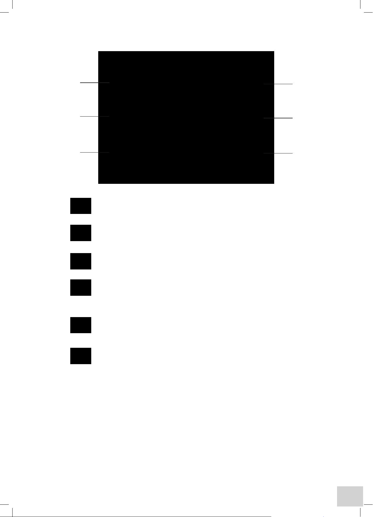
2.1 UNPACKING INSTRUCTIONS
•
Refer to label 1 on carton exterior and
ensure instrument type and options/
accessories supplied are correct. Refer to
Distributor in the event of any discrepancy.
•
Check each item as it is removed from
the packaging to ensure it is correct and
undamaged. Refer to Distributor if any item is
missing or damaged.
•
Remove Documentation carton 2. Note
that this contains the Instruction Manual and
other important documents, which MUST
be retained for future reference. Other small
items (CD ROM, SD Card etc) will also be
found inside this carton.
•
Please take some time to familiarise yourself
with the contents of the Instruction Manual
before using the instrument for the first time.
•
Remove the cardboard packing piece 3 and
place to one side.
•
Remove the two foam packing pieces 4 and
place these to one side.
•
Grasp the instrument 5 (which will be sealed
in a polythene bag) firmly at each end, and lift
out of the carton to place on an adjacent flat,
firm and clean surface.
The instrument weighs approximately 10 Kgs.
PLEASE TAKE CARE WHEN LIFTING.
•
Remove the Accessory carton 6. Note that
this contains the Power and USB cables
together with any sample cells or other items
that may have been ordered. Refer to the
Instruction Manual to ensure accessories are
installed correctly before using the instrument
for the first time.
Disposal of Packaging
It is recommended that the Instrument packaging be retained for possible future long-term
storage or transportation. Please note that the Manufacturer or Distributor cannot be held
responsible for any damage incurred as a result of transportation of an inadequately packed
instrument.
2
3
4
5
6
1
Page 16

14
If you wish to dispose of the instrument packaging, please do so in an environmentally
responsible manner. Please refer to the following guidelines: -
Cardboard packing items are made from paper sourced from recycled fibres
or managed forests and can be 100% recycled where appropriate facilities
exist. Ensure cartons are crushed or flattened before disposal.
Foam packing pieces are manufactured with a reprocessed polyethylene content and can be
easily recycled with other low-density polyethylene (LDPE) materials. Polyethylene foam is
manufactured by a CFC and HCFC free process and contains less than 100ppm heavy metal
content. The European Union Packaging Directive confirms that recovery by means of wasteto-energy is a sensible waste management alternative. The Polyethylene foam burns cleanly
and contributes a high calorific value.
2.2 INSTALLATION
2.2.1 LOCATION
In ideal circumstances the installation environment will be clean, dry and dust free with the instrument
protected from extreme variations in ambient lighting and temperature change. Ensure the unit is
positioned so that the mains on/off switch is accessible. If a safety problem should be encountered,
switch off at the mains socket and remove the plug from the supply.
Where conditions are less than ideal, maintenance and cleaning must be carried out regularly and
additional protection offered where possible.
The optional dust cover should be used to protect the instrument when not in use.
2.2.2 SUPPLY VOLTAGE
The 67 series spectrophotometers are powered by a universal switch-mode power supply that operates
from a 90-264Vac mains supply. The correct lead for your supply should be selected.
2.2.3 MAINS CONNECTIONS
The leads supplied have a moulded on plug. However, if this is removed for any reason the wires in the
mains lead are colour coded to conform to the internationally recognised standard such that:
UK CONNECTIONS US CONNECTIONS
Brown Live Black Live
Blue Neutral White Neutral
Green/Yellow Earth Green Earth
Safety
When disposing of any removed plug the connectors must be removed or made incapable of
insertion into a mains socket.
Page 17
15
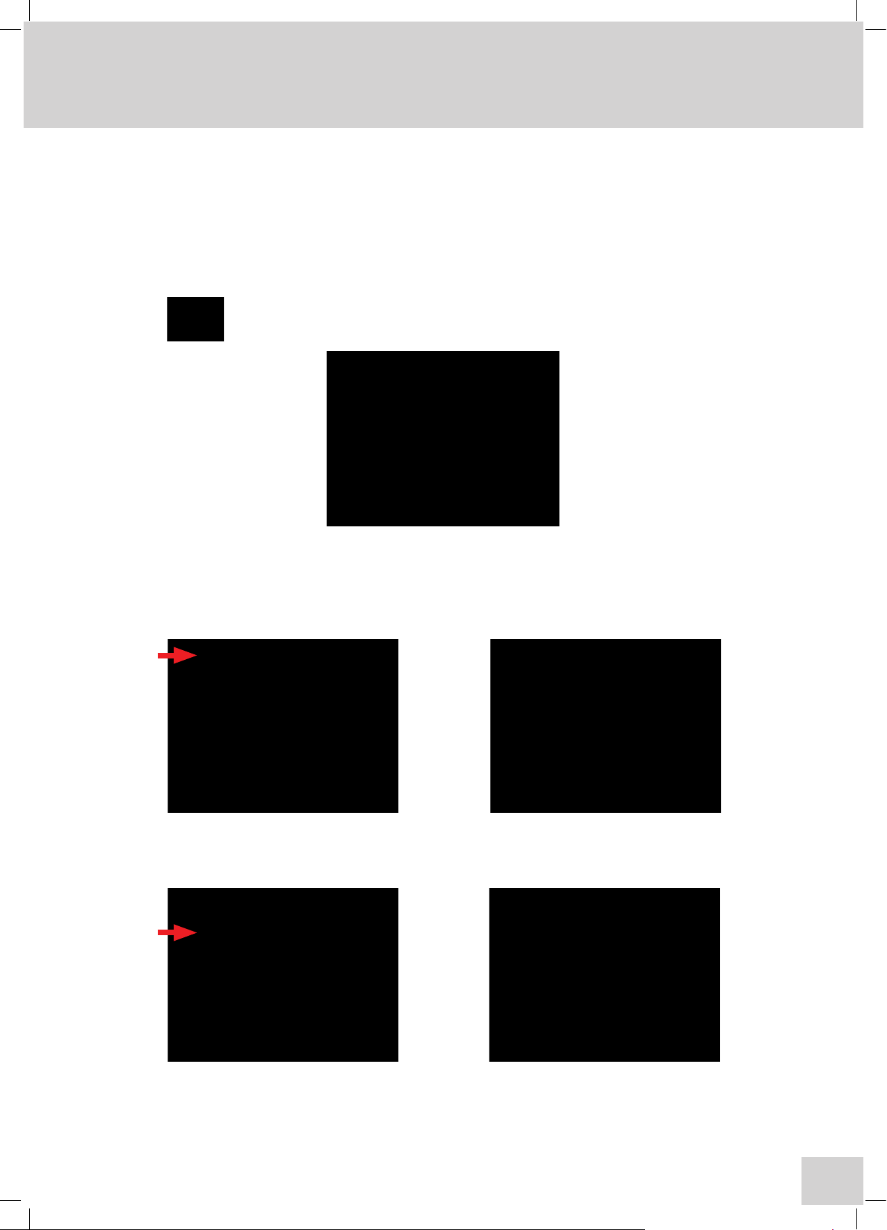
2.2.4 TOUCH SCREEN FUNCTIONS
1. Standby – this key can be used to enter the standby mode during operation.
2. Instrument Settings – this key can be used to access instrument set up parameters
including user creation, PIN codes, language options, date and time settings, administrative
functions and instrument identification details.
3. Back key – this is used to return to a previous menu level.
4. Save key – pressing this key saves methods and/or data. If an external card is not fitted
then methods/data will automatically be saved to internal memory. If an SD card is inserted
or removed during operation relevant messages and options are given to select the desired
media.
5. Toolbar key – this key is only functional on the completion of measurements and
gives access to the available data manipulation options. The function of this key is context
sensitive, enabling different sets of tools depending on the mode of operation in use.
6. Printer key – this key will initiate a print out to either the internal or external printer unit
via the selected settings options in each mode of operation.
1
2
3
6
5
4
Page 18

16
2.2.5 TOOLBAR ICONS
The spectrophotometer can be used for making measurements at any time without the need for
logging in; but many benefits will be lost and results cannot be saved, only printed.
The Method Screen options will only be displayed if the user logs in. If the user is not logged in the
instrument will automatically display the main measurement screen, with settings at their last used levels.
Method Screens
Methods are stored sequentially by measurement mode. Once the first page is full (8 methods for the
selected mode) cursor arrows are displayed enabling the user to browse to subsequent or previous
pages of 8 methods.
Alternatively, pressing one of the alphanumeric keys along the bottom of the screen will display all
available methods with the initial character that is highlighted.
Note: Repeated pressing of a key sequentially highlights the characters between those displayed.
Create a New Method
For the following functions first touch a method or result to select it.
Open the Selected Method
Erase the Selected Method/Result
Browse Results – linked to the selected method
Open specific results in the selected batch
Page 19

17
Photometrics Mode
Mode settings – method name, wavelength, method security (if logged in)
Accessory options – varies with type of accessory module fitted
Allows selection of internal or external printer
Allows set-up of batch ID and the Auto Log options
Press to accept settings entered
Spectrum Mode
Mode settings – method name, measurement mode, wavelength range, plot interval,
method security (if logged in)
Analysis Points – up to 30 wavelengths at which absorbance will be reported
Measurement display – auto scaling, axis setting and colour selection
Accessory options – varies with type of accessory module fitted
Allows selection of internal or external printer, graph details, batch ID and enables or disables
the Auto Log feature
Press to accept settings entered
Page 20

18
Multi-Wavelength Mode
Mode settings – method name, measurement type, reading type, sample style, method
security (if logged in)
Setting wavelengths – allows from 2 to 4 wavelengths to be set
Calculations - allows the selection of calculations and constants
Accessory options – varies with type of accessory module fitted
Allows selection of internal or external printer, graph details, batch ID and the Auto Log
options
Press to accept settings entered
Page 21

19
Kinetics Mode
Mode settings - method name, wavelength, measurement mode, run settings, method
security (if logged in)
Calibration – allows setting of Concentration cal standard, factor, resolution and units of
measurement
Measurement display – allows auto scaling, axis setting and colour selection
Accessory options – varies with type of accessory module fitted
Allows selection of internal or external printer, graph details, batch ID and the Auto Log
options
Press to accept settings entered
Page 22

20
Quantitation Mode
Mode settings – method name, measurement mode, wavelength, resolution, units of
measurement, replicates set up, method security (if logged in)
Calibration – allows the number and levels of standards to be set
Measurement display – allows selection of type of curve fit, auto scaling, axis setting and
colour selection
Accessory options – varies with type of accessory module fitted
Allows selection of internal or external printer, graph details, batch ID and the Auto Log
options
Press to accept settings entered
Status Bar
To view the set parameters in any of the measurement modes press the status bar once and a drop
down menu will appear. Pressing this bar again will return it to its original status.
Page 23

21
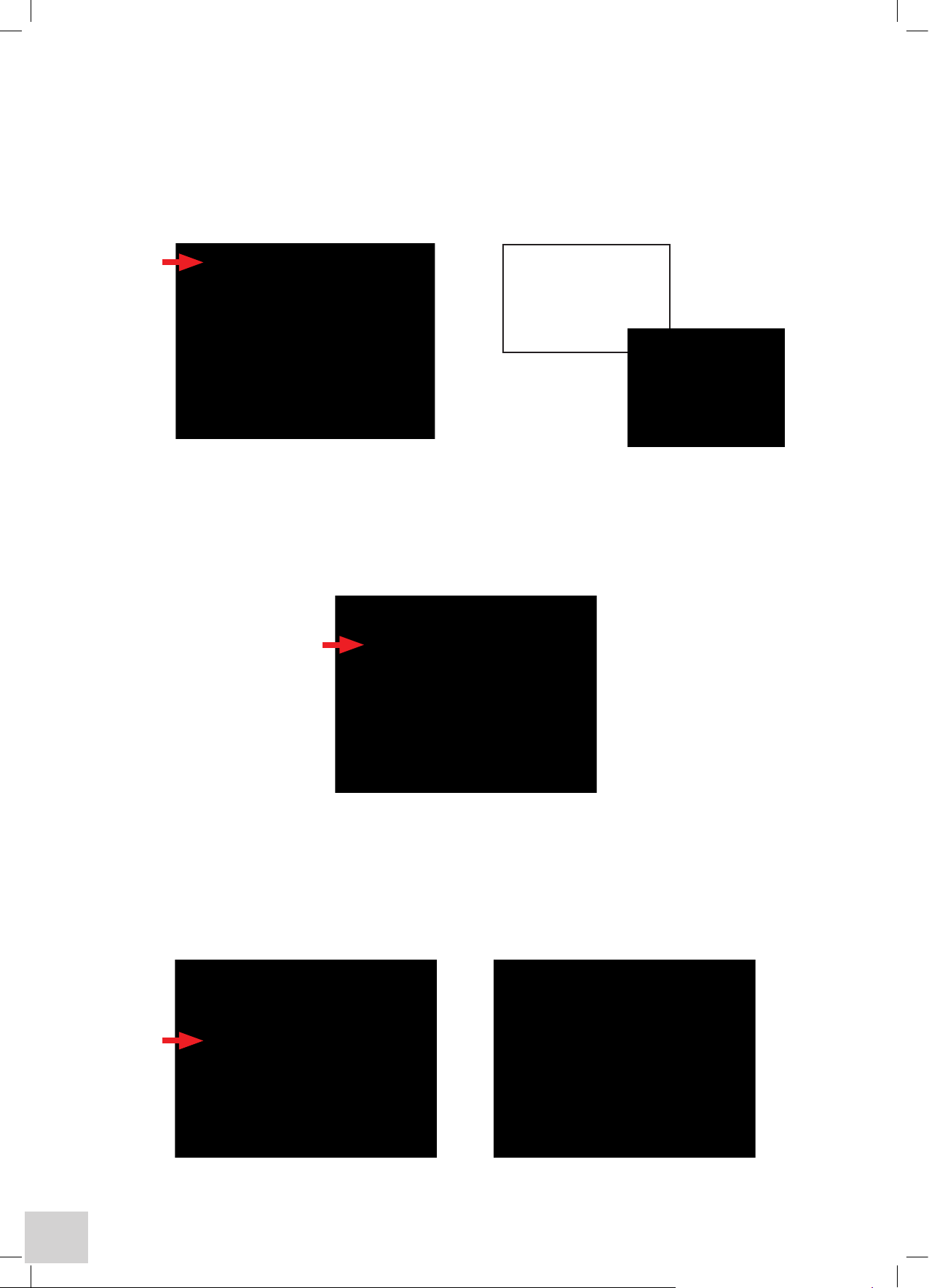
2.2.6 REAR PANEL LAYOUT
Power Switch On/Off switch for the unit.
Power In Socket IEC type connection socket for the mains supply cable.
Printer Socket 25 way Centronics parallel output socket compatible with Postscript printers.
Analogue Output 2 x 4mm pin sockets for analogue devices.
USB Socket type B connector for communication to PC.
SD Card Socket will accept 128MB to 2GB SD or Multi-media memory cards.
Printer socket
USB SocketAnalogue O/P SD Card Socket
Power
switch
Power in socket
Page 24

22
2.2.7 POWER ON AND SELF-TESTS
response
Dark test… Checks detector and light seal on sample chamber
Wavelength calibration… Performs a wavelength calibration
followed by the Main Menu Screen:
This screen gives you access to the five operating modes that can be used directly for making
measurements without logging in. It should be noted that if the user is not logged in results can
only be viewed and printed but not stored. In addition, methods cannot be created or retrieved.
Note: For the Model 6700 allow 30 minutes warm up prior to use.
For all models the LCD display may take up to 10 minutes to reach full brightness.
Connect the mains supply cable to the rear panel mains input socket and plug the other end into a
suitable mains supply socket.
Lift the sample chamber lid on the instrument and ensure that there is no sample or other item present
in the sample holder, close the lid.
Switch on the supply socket, then the instrument, using the Power switch located on the rear panel.
The instrument will then perform the power on self-test protocol. The power on and self-test screens
will be shown:
System test… Checks internal connections / Checks internal and external memory status
Accessory test… Checks for fitted ‘active’ accessories / Verifies communication and
Page 25

23
SECTION 3 - Systems of Operation
3.1 MULTI-USER AND FREE OPERATION
The 67 Series spectrophotometers focus on secure, multi-user operation. But to ensure that anyone
can acquire quality results in an emergency or when otherwise required (stat or free operation), they
may also be used without the operator having to log in. Such free operation is restricted to making
measurements with no access to methods while results will only be displayed or printed.
Secure, multi-user operation requires each designated user to enter a PIN code to access methods
and results. When creating methods a user can opt to share them with other users, as Public (can
be modified) or Read-Only (can be used but not modified), or to keep them Personal. Up to 10
users and a Supervisor with administrative rights can be set up on each instrument but by using the
removable media (see below) an almost infinite number of users can be securely accommodated.
3.2 MEMORY STRUCTURE
The 67 Series spectrophotometers have a dual memory structure based on removable media and
fixed internal memory. The removable media is based on SD memory cards with a wide range of
capacities available.
The following table gives details of the removable media available (subject to change by manufacturers
range consolidation):
Card Capacity
2 GB
3.2.1
MEMORY SELECTION
When the power is turned on the internal memory is selected as the default memory location, even
if a removable memory card is fitted in the instrument. If the user inserts a removable media memory
card during use a message will be displayed giving the user the option to switch the default memory
location to the removable media memory card so that any methods and results that are saved are sent
to this card. Should the card be removed during use a warning message will be displayed and the
internal memory will then be set as the default location.
SD Card Part Number
019 133
Page 26
24
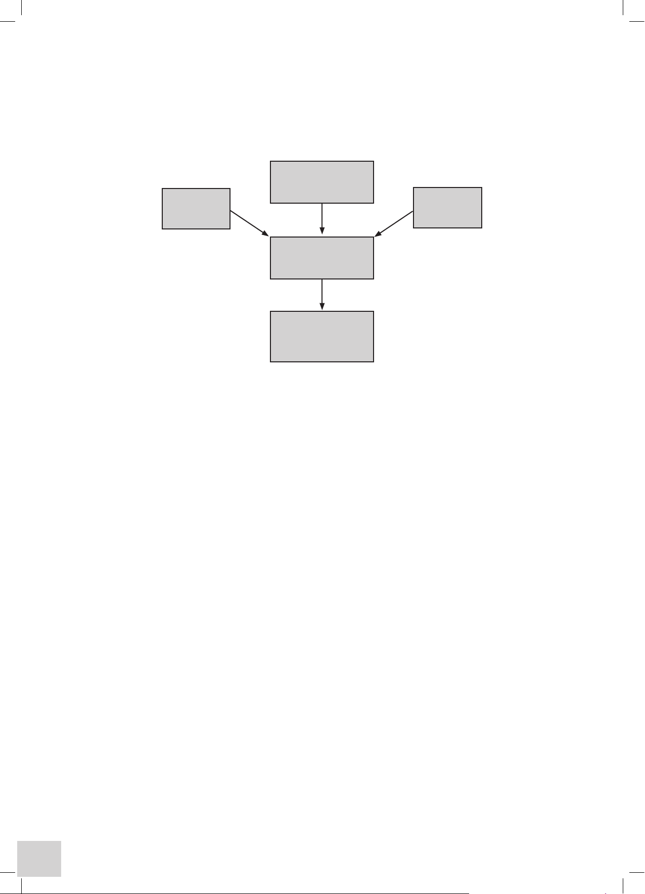
3.2.2 MEMORY HIERARCHY
The top level of the memory hierarchy is the user, defined by a user name and recognised by their
unique PIN code. In general it is considered that this will be an individual but in practice this can
be made more flexible by considering the user as a group sharing the same PIN code. For instance
different departments or shifts could be identified by their own PIN codes.
Different types of tests could also be separated by PIN codes with only users trained in carrying out
specific tests given the relevant PIN codes to access the tests for which they have been trained. In
education a PIN code for each semester or part of the curriculum would restrict students or year
groups access to only the current work, protecting that to be used in the future. The implementation
and benefits of this function are only limited by the imagination.
Below the user level are the Methods created by that user or for that group, and those with Public or
Read-Only status that all users can access, below each method are the results stored by the user for
THAT METHOD.
3.3 CREATING METHODS
The ability to create and re-call methods is only available to logged in users.
To log in touch the Log In… key on the bottom right-hand side of the Main Menu screen that is
displayed after completion of the start-up tests.
A table of users is then displayed, touching your name (department, user group or other identifier)
then brings up a numeric entry screen for inputting the four digits of the relevant PIN code.
For first time use the only user in the table will be the Supervisor with a default PIN Code of 1234
(once logged in this can subsequently be changed to a number combination of the Supervisor’s
choice).
By pressing the Settings key on the display surround and selecting the Administrative Functions
option the Supervisor can create new users. On creation a new user has a default PIN Code of 0000
that, like the Supervisor’s, can be changed by selecting User Preferences, then Adjust PIN Code.
NOTE: Once the Supervisor’s PIN CODE is changed it must be kept safe as there is no other way of
accessing this function – however the Supervisor does have the right to re-set other users’ PIN Codes
back to the default.
For further information on these functions see the Section on Instrument Settings and
Administrative Functions.
Read-Only
Methods
User defined
by PIN Code
Public
Methods
Methods
Created by User
Results appended
to user accessible
methods
Page 27

25
When successfully logged in the user is returned to the main menu screen from which the required
mode of measurement can be selected.
The Browse screen is then displayed from which an existing method can be re-called using the
alphanumeric search keys along the bottom menu bar. If insufficient methods have been created to fill
the first page all available methods will be shown.
3.4 FILE & DATA MANAGEMENT
Save Tools Print Settings Erase Search Open Save
Results Results
Saving Methods
Having entered all your required settings on the tabbed pages the method can be saved by simply
pressing the Save key on the display surround. If you do not save at this point but continue to make
measurements using the method, it will automatically be saved when you save the first result.
If you continue without saving a result you will be prompted to save the method as you exit the
operating mode or return to the settings options. Alternatively, when the Auto Log option is set to
On or Timed and the destination option is Memory all results will be saved automatically.
Sharing Methods
Methods can be shared with other users by setting the security level at either Read-Only where other
users can use but not modify the method or, Public where they can use and modify the method.
Other users must then ensure that under Method View Settings (Settings/User Preferences/Method
View Settings) they have enabled Public and/or Read-Only methods or turned All Methods on.
Recalling Methods
Following selection of the operating mode from the main menu the method browse screen is
displayed. This will show all methods that the current user has access to, based on their selections in
the Method View Settings (refer to Sharing Methods). If the first page is full, cursor arrows will be
displayed to enable navigation to and from additional pages.
Alternatively, selection may be made using the alphanumeric menu bar at the bottom of the screen.
Repeated pressing of each character set will display the full alphanumeric range and the screen will
show all methods starting with the highlighted character.
Touch the required method when it is displayed on the screen to highlight it, touch the Open File icon
to display the main measurement screen for that method.
Editing Methods
Use the Recalling Methods procedure to recall the required method. With the measurement screen
displayed touch the Settings option. Adjust the settings as required and touch the Enter icon
on completion. The modified method can then be saved by pressing the Save key on the display
surround. If you do not save at this point but continue to make measurements using the method, it
will automatically be saved when you save the first result. If you continue without saving a result you
will be prompted to save the method as you exit the operating mode or return to the settings options.
Note: If the Method name was not changed during editing it will be saved with the same name but
with a new date and time to ensure traceability. If the old method is no longer required it should be
deleted as detailed in Deleting Methods.
Page 28

26
Deleting Methods
To delete methods highlight the required method in the Browse screen as described in Recalling Methods and
then touch the Erase icon.
A warning message will be displayed to ensure this action is required. On confirmation the selected file will be
deleted.
If the current user does not have the required privileges to delete the selected method then an information
message will be displayed advising that the method cannot be deleted.
Privileges required for deleting designated methods:
Public Methods – only the Supervisor and Originator can delete these.
Read-Only Methods – only the Supervisor and Originator can delete these.
Personal Methods – Only the Originator can delete these methods. (The Supervisor can delete these by re-
setting the Originator’s PIN code and then logging in as the Originator).
Saving Results
After completion of a measurement the result can be saved by simply pressing the Save key on the display
surround. The result is saved under the method that created it, with the entered Batch ID and an incremental
number along with the time and date of the measurement. Results can also be saved as part of the Auto Log
function by selecting Memory under the Auto Log option, which will vary depending on the type of sampling
accessory fitted.
Printing Results
After completion of a measurement the result can be printed, by simply pressing the Print key on the display
surround. The result will be printed to either the internal or external printer, as selected by the user in the Printer
Settings option.
The first result of any new batch is preceded by a print header, which gives details of the method settings and
Batch ID. Results can also be printed as part of the Auto Log function, which will vary depending on the type of
sampling accessory fitted.
Recalling Results
Stored results are always directly linked to the method that created them. To access results first recall the method
as described in Recalling Methods. With the method highlighted touch the Search Results icon. This will open
a screen detailing all results available to the current user. Touch the required result or batch (depending on the
mode) and then the Open Specific Result icon. This will display the results on the screen. The Tools option
can then be used to work on these results (depending on mode). It is also possible to print the result by simply
pressing the Print key on the display surround. Options to print to the Internal or External printer or to the CSV
file will be displayed. Printing to the CSV (Comma Separated Values) file will save the data in CSV format on the
external data card. (If a card is not fitted the instrument will display a prompt). This is in text format and can be
viewed and printed in Excel
®
.
In Kinetics mode an additional option is available (Analogue Mode). This allows results to be output via the rear
panel analogue sockets to a chart recorder or similar device.
Sharing Results
Results attached to Personal Methods cannot be accessed by any other user.
Results attached to Read-Only and Public Methods can be accessed by all users, based on their current
Method View Settings.
Page 29
27
SECTION 4 - Instrument Settings
4.1 MENU OPTIONS
A number of settings can be stored for each signed in user including language, method view settings,
display brightness and time/date display choices so that these do not have to be reset each time a new
user logs in. These can be found under User Preferences.
Note: Administration Functions and Memory Manager options will be greyed out and unavailable
unless the Supervisor has logged in.
– When switching on the product for the first time, or if the previously entered settings
need to be checked, this key should be selected to give access to the following display:
4.2 SET TIME & DATE
To set the correct date and time select the Set Time & Date key. The time and date can be reset using
the up and down arrows. To accept the new settings select the Enter key. Touching the Cancel key
will return you to the main menu without accepting any alterations to the current settings.
4.3 USER PREFERENCES
Selecting User Preferences gives access to the following options:
These settings are saved for each user and the individual’s selections are retained when that user logs
in. Adjust User PIN and Method View Settings options are only available to the Supervisor.
Note: Adjust User PIN and Method View Settings will only be available to the Supervisor.
Page 30
28
4.3.1 ADJUST USER PIN – available to logged in users only
To alter your User PIN select the Adjust User PIN key. A warning message will be shown prior to the
numeric keypad. Enter your new 4 digit code using the numeric keypad as shown below. The Del key
allows individual digits to be changed. The Cancel key will return you to the previous menu without
altering the original PIN code. The Clear key will clear all digits entered from the screen. The Enter key
accepts the new code and returns you to the previous menu.
4.3.2 LANGUAGE
The preferred language can be selected using the Language key. Select the preferred language from
the options available and press the OK key and the will update to show all screens in English, French,
German, Italian or Spanish.
4.3.3 METHOD VIEW SETTINGS – available to logged in users only
To simplify operation it is possible to restrict the methods displayed by their allocated category.
Selecting Method View Settings enables My Methods (Personal) to be hidden (Off) or displayed
(On). Similarly, Read Only Methods and Public Methods can be hidden or displayed. To simply
display all method categories toggle All Methods to the On status.
Please ensure you remember
your PIN code or store it in a
secure location, or access to
your personal data will
be lost.
OK
Page 31

29
4.3.4 TOUCH SCREEN CLICK
The touch screen can be operated with or without an audible click each time a key is touched. The
click can be toggled on or off via the Touch Screen Audible Click: Off key.
4.3.5 BRIGHTNESS
Selecting the Brightness key and then using the left and right arrows on the display shown below can
adjust the brightness of the display. Selecting the Enter key will update the display setting and return
the instrument to the previous display.
4.3.6 ADJUST DATE & TIME
Selecting the Date & Time Preferences key allows the user to display either the time or date. In
addition the date format can be set to either DD/MM/YY or MM/DD/YY. Once the preferred option
is selected, pressing the Back key on the display surround once will return you to the previous menu.
Pressing the Back key twice returns the instrument to the Main Menu.
Page 32

30
4.4 ABOUT
Selecting the About key provides information relating to instrument ID and signed in user details.
Selecting the OK key returns the instrument to the previous menu.
4.5 FORM FEED
Selecting the Form Feed key will feed additional paper through the mechanism of the connected
printer to separate results or enable a clean area for tearing off.
4.6 ADMINISTRATION FUNCTIONS
This function is only available to the Supervisor. It gives access to all user related information. It gives
access to Instrument ID, screen dump control and Modify Users sub-menu.
Page 33

31
4.6.1 INSTRUMENT ID
Selecting the Instrument Id: 67XXCVS key allows the supervisor to alter the instrument identification
code. This is entered by use of the alphanumeric keypad. The Cancel key will return you to the
previous menu without altering the original ID. The Del key allows individual letters or digits to
be removed. The Clear key will clear all digits entered from the screen. The Enter key accepts
the new ID and returns you to the previous menu. For laboratories with more than one 67 series
spectrophotometer it is useful to change this ID to the serial number, department or other unique
identifier for easy recognition of different instruments.
4.6.2 SCREEN DUMP
The screen dump function can be enabled or disabled.
4.6.3 MODIFY USERS
This gives access to the sub-menu which allows the supervisor to modify user parameters.
Page 34

32
4.6.3.1 CREATE NEW USER
Selecting the Create New User key allows the supervisor to enter an additional user on to the
instrument using the alphanumeric keypad as shown. The Clear key will clear all information entered
from the screen. The Del key allows individual letters or digits to be removed. The Cancel key will
return you to the previous menu without adding a new user. The Enter key accepts the new ID and
returns you to the previous menu.
4.6.3.2 DELETE USER
Selecting the Delete User option allows the supervisor to delete a specific user from the instrument.
When the user name is selected from the list the following warning message is displayed:
If Yes is selected the instrument will update and the user will be removed from the instrument.
If Cancel is selected the user will not be deleted from the instrument.
4.6.3.3 DELETE ALL USERS
Selecting this option allows the supervisor to delete all current users (except the supervisor) from the
instrument. The following warning message is displayed:
If Yes is selected the instrument will update and all users will be removed from the instrument.
If Cancel is selected all users will remain on the instrument.
6715 CVS
All users will be permanently
deleted from the instrument.
Are you sure you wish to
continue?
Yes Cancel
6715 CVS
This user will be permanently
deleted from the instrument.
Are you sure you wish to
continue?
Yes Cancel
Page 35

33
4.6.3.4 RESET USER PIN
This option allows the supervisor to reset an individual users PIN code.
Select the Reset User PIN option from the screen. The list of current users will then be displayed on
screen. Select the user. The warning message: ‘Are you sure you wish to continue’ will be displayed
with the options to accept or cancel.
If Yes is selected the user PIN will be reset to the default value and the supervisor has access to all
information relating to that user.
If Cancel is selected no changes will be made to the user codes and the instrument will return to the
Select User Menu.
4.7 MEMORY MANAGER
This option is available only to the Supervisor and allows transfer of data, methods and user
preferences to and from the instrument memory. This enables backup of information stored in the
instrument memory and on any removable media used. Both memory locations can also be formatted.
WARNING – this will permanently delete all information stored in the location being
formatted.
Page 36

34
SECTION 5 - Photometrics Mode
5.1 PRINCIPLES OF MEASUREMENT
The simplest mode of the spectrophotometer is Photometrics. A measurement is made of either the
absorbance or transmittance of a sample. The measurement is at a single wavelength, at one point in
time, with no additional calculations.
Select Photometrics from the Main Menu:
If the user is not logged in (Free Operation) the main measurement screen will be displayed (refer
Section 5.2).
5.2 FREE OPERATION
Settings
If the user is not logged in then the screen will show the following message when the Photometrics
Mode key is selected from the Main Menu:
If Yes is selected the instrument will go to the main measurement screen.
If No is selected the instrument will return to the main menu where the user has the option to Log In.
As you are not logged in
you will not be able to save
results. Are you sure you
want to continue?
Yes No
Page 37

35
To enter the appropriate parameters for the sample(s) to be tested select the Settings key and the
instrument will display the following screen:
Mode settings - method ID, wavelength, method security (if logged in)
Accessory options - varies with type of accessory module fitted
Allows selection of internal or external printers
Allows set-up of batch ID and enables or disables or disables the Auto Save feature
Press to accept settings entered
Setting Method ID
To allocate a Method name select the Method key and enter the preferred name using the
alphanumeric keypad. The Clear key will clear all information entered from the screen. The Del key
allows individual letters or digits to be removed. The Cancel key will return you to the previous menu
and the method name will remain as Default Method. The Enter key accepts the new method ID and
returns you to the previous menu.
Note: The new Method ID can only be used to identify the method on a printout to the internal or
external printer module. The generic user has no additional facility to store or recall results or methods.
Page 38

36
Setting Wavelength
Select the Wavelength key and enter the wavelength using the numeric keypad. The Clear key will
clear all information entered from the screen. The Del key allows individual digits to be removed. The
Cancel key will return you to the previous menu and the wavelength will not alter. The Enter key
accepts the new wavelength and returns you to the previous menu. (At certain wavelengths order
selecting filters may be heard switching in or out). Select the Enter key to confirm and the display will
update to show the new wavelength.
Using the Back key to escape settings will
display:
If Yes is selected all set information will be
lost and the instrument will return to the main
measurement screen.
If No is selected the instrument returns the
Settings screen as shown.
To accept all entered information touch the Enter key to confirm. The instrument will show the main
measurement screen with the updated information.
Setting Method Security
This option is only applicable to logged in users.
Batch ID and Auto Logging can be entered via the Save icon.
Setting Batch ID
Select the Batch ID key and enter the Batch code using the alphanumeric keypad. Select the Enter
key to accept or Cancel to remain as a default.
6715 CVS
Continue? , if so you will
lose any changes you have
made.
Yes Cancel
Page 39

37
Auto Log Settings…
Selecting Auto Log Settings… opens a dedicated sub-menu.
This option can be toggled between On, Off or Timed.
Auto Log Settings
This option can be toggled between Off/On/Timed. When Auto Log option is selected to On the
user can set:
the destination, (toggles between internal or external printer and memory).
When the Auto Log option is set to Timed the user can set:
the timed interval between 3 and 9999 seconds using the numeric keypad;
the destination (toggles between internal or external printer and memory);
the number of repetitions from 2 to 999 using the numeric keypad.
To view the set parameters touch the status bar once and a drop down menu will appear giving this
detail. Touching the bar again will return it to its original position.
Note: If the Auto Log Timed option is selected the Read key will be replaced with Start/Stop keys.
Page 40

38
5.3 LOGGED IN MEASUREMENT
PIN Codes – each user is allocated a 4 digit PIN code that is required when logging in.
Select Log In… from the Main Menu and a list of users will be shown. Select the appropriate user
name and a numeric keypad will be displayed.
Enter your 4 digit PIN code and touch the Enter key to confirm.
Once logged in method screen options will be displayed:
Methods are stored sequentially by measurement mode. Once the first page is full (8 methods for
the selected mode) cursor arrows are displayed in the top corners enabling the user to browse to
subsequent or previous pages of 8 methods.
Alternatively, pressing one of the alphanumeric keys along the bottom of the screen will display all
available methods with the initial character that is highlighted.
Note: Repeated pressing of a key sequentially highlights the characters between those displayed.
Create a New Method
For the following functions first touch a method or result to select it.
Open the Selected Method
Erase the Selected Method
Browse Results – linked to the selected method
Open specific results in the selected batch
Page 41

39
Creating a New Method
Settings
To enter the Method ID, appropriate wavelength for the sample(s) to be tested and the level of Method
Security required for the method being created select the New File icon
Setting Method ID
To allocate a Method name select the Method key and enter the preferred name using the
alphanumeric keypad. The Clear key will clear all information entered from the screen. The Del key
allows individual letters or digits to be removed. The Cancel key will return you to the previous menu
and the method name will remain as Default Method. The Enter key accepts the new method ID and
returns you to the previous menu.
Setting Wavelength
Select the Wavelength key and enter the wavelength using the numeric keypad. The Clear key will
clear all information entered from the screen. The Del key allows individual digits to be removed. The
Cancel key will return you to the previous menu and the wavelength will not alter. The Enter key
accepts the new wavelength and returns you to the previous menu. (At certain wavelengths order
selecting filters may be heard switching in or out). Select the Enter key to confirm and the display will
update to show the new wavelength.
Using the Back key to escape settings will display:
If Yes is selected all set information will be
lost and the instrument will return to the main
measurement screen. If No is selected the
instrument returns the Settings screen as shown.
6715 CVS
Continue? , if so you will
lose any changes you have
made.
Yes Cancel
Page 42

40
Setting Method Security
The 67 Series spectrophotometers can support up to 10 individual users plus one Supervisor who has
full administrative rights.
Logged in users can create methods with three levels of security options:
Personal – these methods are only accessible by the originator.
Public – these methods are available for use and modification by any logged in user.
Read-Only – these methods can be accessed by all logged in users, but can only be modified by the
originator.
The preferred level of protection can be achieved by selecting the Method Security key that toggles
between Personal, Public and Read-Only options.
To accept the selected options touch the Enter key to confirm. The instrument will show the main
measurement screen with the updated information.
Setting Batch ID
Select the Batch ID key and enter the batch code using the alphanumeric keypad. Select Enter to
accept or Cancel to remain as a default.
Page 43

41
Auto Log Settings…
Selecting Auto Log Settings… opens a dedicated sub-menu.
This option can be toggled between On, Off or Timed.
Auto Log Settings
This option can be toggled between Off/On/Timed. When Auto Log option is selected to On the
user can set:
the destination, (toggles between internal or external printer and memory).
When the Auto Log option is set to Timed the user can set:
the timed interval between 3 and 9999 seconds using the numeric keypad;
the destination (toggles between internal or external printer and memory);
the number of repetitions from 2 to 999 using the numeric keypad.
To view the set parameters touch the status bar once and a drop down menu will appear giving this
detail. Touching the bar again will return it to its original position.
Note: If the Auto Log Timed option is selected the Read key will be replaced with Start/Stop keys.
Page 44

42
File & Data Management
Save Tools Print Settings Erase Search Open Save
Results Results
Saving Methods
Having entered all your required settings on the tabbed pages the method can be saved by simply
pressing the Save key on the display surround. If you do not save at this point but continue to make
measurements using the method, it will automatically be saved when you save the first result.
If you continue without saving a result you will be prompted to save the method as you exit the
operating mode or return to the settings options. Alternatively, when the Auto Log option is set to
On or Timed and the destination option is Memory, all results will be saved automatically.
Sharing Methods
Methods can be shared with other users by setting the security level at either Read-Only where other
users can use but not modify the method or, Public where they can use and modify the method.
Other users must then ensure that under Method View Settings (Settings/User Preferences/Method
View Settings) they have enabled Public and/or Read-Only methods or turned All Methods on.
Recalling Methods
Following selection of the operating mode from the main menu the method browse screen is
displayed. This will show all methods that the current user has access to, based on their selections in
the Method View Settings (refer to Sharing Methods). If the first page is full, cursor arrows will be
displayed to enable navigation to and from additional pages. Alternatively, selection may be made
using the alphanumeric menu bar at the bottom of the screen.
Repeated pressing of each character set will display the full alphanumeric range and the screen will
show all methods starting with the highlighted character.
Touch the required method when it is displayed on the screen to highlight it, touch the Open File icon
to display the main measurement screen for that method.
Editing Methods
Use the Recalling Methods procedure to recall the required method. With the measurement screen
displayed touch the Settings option. Adjust the settings as required and touch the Enter icon
on completion. The modified method can then be saved by pressing the Save key on the display
surround. If you do not save at this point but continue to make measurements using the method, it
will automatically be saved when you save the first result. If you continue without saving a result you
will be prompted to save the method as you exit the operating mode or return to the settings options.
Note: If the Method name was not changed during editing it will be saved with the same name but
with a new date and time to ensure traceability. If the old method is no longer required it should be
deleted as detailed in Deleting Methods.
Deleting Methods
To delete methods highlight the required method in the Browse screen as described in Recalling
Methods and then touch the Erase icon. A warning message will be displayed to ensure this action is
required. On confirmation the selected file will be deleted.
If the current user does not have the required privileges to delete the selected method then an
information message will be displayed advising that the method cannot be deleted.
Page 45

43
Privileges required for deleting designated methods:
Public Methods – only the Supervisor and Originator can delete these.
Read-Only Methods – only the Supervisor and Originator can delete these.
Personal Methods – Only the Originator can delete these methods. (The Supervisor can delete these
by re-setting the Originator’s PIN code and then logging in as the Originator).
Saving Results
After completion of a measurement the result can be saved by simply pressing the Save key on the
display surround. The result is saved under the method that created it, with the entered Batch ID and
an incremental number along with the time and date of the measurement. Results can also be saved
as part of the Auto Log function by selecting Memory under the Auto Log option, which will vary
depending on the type of sampling accessory fitted.
Printing Results
After completion of a measurement the result can be printed, by simply pressing the Print key on the
display surround. The result will be printed to either the internal or external printer, as selected by the
user in the Printer Settings option.
The first result of any new batch is preceded by a print header, which gives details of the method
settings and Batch ID. Results can also be printed as part of the Auto Log function, which will vary
depending on the type of sampling accessory fitted.
Recalling Results
Stored results are always directly linked to the method that created them. To access results first recall
the method as described in Recalling Methods. With the method highlighted touch the Search
Results icon. This will open a screen detailing all results available to the current user. Touch the
required result or batch (depending on the mode) and then the Open Specific Result icon. This
will display the results on the screen. The Tools option can then be used to work on these results
(depending on mode). It is also possible to print the result by simply pressing the Print key on the
display surround. Options to print to the Internal or External printer or to the CSV file will be displayed.
Printing to the CSV (Comma Separated Values) file will save the data in CSV format on the external
data card. (If a card is not fitted the instrument will display a prompt). This is in text format and can be
viewed and printed in Excel
®
.
In Kinetics mode an additional option is available (Analogue Mode). This allows results to be output
via the rear panel analogue sockets to a chart recorder or similar device.
Sharing Results
Results attached to Personal Methods cannot be accessed by any other user.
Results attached to Read-Only and Public Methods can be accessed by all users, based on their
current Method View Settings.
Page 46

5.4 PERFORMING MEASUREMENTS – all users
Once the required settings have been confirmed the main Photometrics measurement screen will be
shown. This screen shows the absorbance value, followed by the Transmittance value and then the
selected wavelength. At the top of the screen Method ID and Batch number, time or date is displayed.
Zeroing the Instrument
Insert a cuvette containing a blank solution into the sample holder and close the sample chamber lid.
(Test tubes or other sample containers may be used depending on the sample holder accessory fitted).
Select the Zero key. The messages Calibrating Dark Level… and Calibrating Light Level...’ are
displayed momentarily. Once the measurement is completed the screen will update to show:
Note: In general the blank solution should contain everything that is in the sample except the
colour-producing component. For specific information reference should be made to the procedure or
application being followed. For enhanced reproducibility matched cuvettes should be used.
Measuring the Sample
Remove the cuvette containing the blank solution and insert the first sample into the sample holder
and close the sample chamber lid. Select the Read key.
The screen will momentarily display ‘Taking reading. Please wait…’ Once the measurement is
completed the screen will update to show the measured value.
Additional individual samples can be measured by inserting them in the single sample holder and
selecting Read. Alternatively, multiple samples can be measured with the optional 8 or 6 cell changers
or sequentially with the sipper pump accessory.
44
Page 47

45
Section 6 - Spectrum Mode
6.1 PRINCIPLES OF MEASUREMENT
By examining the absorbance or transmittance of the sample over a wavelength range we can partially
characterise the sample. Readings of the sample over a range of wavelengths are made and a graph
is plotted of the absorbance or transmittance at each wavelength. As well as observing good practice
(see Good Practice Guidelines) it must be ensured that the sample is stable for the period of the scan
(maximum 70 seconds).
Select the Spectrum Mode from the Main Menu options.
The method screen options will only be displayed if the user logs in. If the user is not logged in the
instrument will automatically display the main instrument screen, with settings at their last used levels.
6.2 FREE OPERATION
Settings
If the user is not logged in then the main measurement screen will automatically be displayed when
the Spectrum mode is selected from the Main Menu:
To enter the required parameters for the sample(s) under test, select the Settings key and the
instrument will display the following screen:
Page 48

46
Mode settings – method name, measurement mode, wavelength range, plot interval, method
security (if logged in)
Analysis Points – up to 30 wavelengths at which absorbance will be reported
Measurement display – auto scaling, axis setting, colour selection
Accessory options – varies with type of accessory module fitted
Allows selection of internal or external printer, graph details, batch ID and enables or disables
the Auto Log feature
Press to accept settings entered
Setting Method ID
To allocate a Method name select the Method key and enter the preferred name using the
alphanumeric keypad. The Clear key will clear all information entered from the screen. The Del key
allows individual letters or digits to be removed. The Cancel key will return you to the previous menu
and the method name will remain as Default Method. The Enter key accepts the new method ID and
returns you to the previous menu.
Note: The new Method ID can only be used to identify the method on a printout to the internal or
external printer module. The generic user has no additional facility to store or recall results or methods.
Selecting Measurement Mode
The Measurement Mode key toggles between Absorbance and Transmittance.
Page 49

47
Setting Wavelengths
Note: If the start or end wavelength is adjusted so that they are closer than twice the plot interval
then the previously set wavelength will be automatically adjusted to ensure a minimum of two
measurement points.
Setting Start Wavelength
Select the Start Wavelength key and enter the wavelength using the numeric keypad. The Clear key
will clear all information entered from the screen. The Del key allows individual digits to be removed.
The Cancel key will return you to the previous menu and the wavelength will not alter. The Enter key
accepts the new wavelength and returns you to the previous menu. (At certain wavelengths order
selecting filters may be heard switching in or out). Select the Enter key to confirm. The display will
show the entered wavelength.
Setting End Wavelength
Select the End Wavelength key and enter the wavelength using the numeric keypad. The Clear key
will clear all information entered from the screen. The Del key allows individual digits to be removed.
The Cancel key will return you to the previous menu and the wavelength will not alter. The Enter key
accepts the new wavelength and returns you to the previous menu. (At certain wavelengths order
selecting filters may be heard switching in or out). Select the Enter key to confirm. The display will
show the entered wavelength.
Page 50

48
Selecting Plot Interval
Selecting the Plot Interval key allows the user to toggle between 1.0nm, 5.0nm, 0.1nm and 0.5nm.
Using the Back key to escape settings will display:
If Yes is selected all set information will be lost and
the instrument will return to the main measurement
screen. If No is selected the instrument returns the
Settings screen as shown.
To accept the entered information at any time, select the Enter key to confirm. The instrument will
show the main measurement screen with the updated information.
To view the set parameters touch the status bar once and a drop down menu will appear. Touching
this bar again will return it to its original status.
6715 CVS
Continue? , if so you will lose
any changes you have made.
Yes Cancel
Page 51

49
Setting Method Security
This option is only applicable to logged in users.
Setting Additional Set-up Parameters using the Toolbar Icons
Setting Analysis Points
Up to 30 analysis points can be set be selecting the Analysis Points keys and entering the required
wavelength value via the numeric keypad.
It should be noted that a warning message will be displayed if the analysis point(s) set are outside the
spectrum scan range and a warning symbol will be shown next to the entered value.
The Clear Analysis Points option will clear all previously set analysis points.
To delete or edit individual analysis points select
the required analysis point to display:
If Del is selected the analysis point is deleted.
If Edit is selected a new value can be entered
via the numeric keypad.
If an attempt is made to set an analysis point outside the start and end wavelength values the error
message ‘Wavelength for analysis out of spectrum scan range’ will be displayed momentarily and
a triangular symbol will be shown to the side of the incorrect value. This value can be deleted or edited
by selecting the analysis point (in this example 1) and entering a new value within the specified limits.
The analysis points will appear on tags at the relevant point on the spectrum display. They will also be
printed with any printout to the internal or external printer if the Print Data Points option has been
selected.
6715 CVS
What would you like to do to
this analysis point?
Del Edit
Page 52

50
Setting Auto-Scale
The Auto-Scale key toggles between On and Off. With the Auto-Scale function On the instrument
will automatically set the Y-axis maxima to a level that will fit the largest peak and lowest valley in the
display area. This is the best option to choose if the user is uncertain of the limits of the scan.
When set to On the manual settings for Y-axis maximum and minimum are non-functional. These
settings can be changed with Post Scan analysis tools to enable alternative views and printouts after
the scan has been completed.
With the Auto-Scale function set to Off the Y-Axis Minimum enables the lowest displayed level for
the Y-axis to be manually set. Select the Y-Axis Minimum key and a numeric keypad will be displayed
for entry of this value. This value can be between –0.301 and 2.999.
The Y-Axis Maximum enables the highest displayed level for the Y-axis to be manually set. Select the
Y-Axis Maximum key and a numeric keypad will be displayed for entry of this value. This value can
be between 3.000 and –0.300.
Selecting Plot Colour
Selecting the Plot Colour key displays a colour selection screen. Touch any one of the eight colours to
select the preferred plot colour. Once selected, the screen will update to show the selected colour.
Page 53

51
Selecting Axis Colour
Selecting the Axis Colour key displays a colour selection screen. Touch any one of the eight colours to
select the preferred colour. Once selected, the screen will update to show the selected colour.
Setting Batch ID
Select the Batch ID key and enter the batch code using the alphanumeric keypad. Select Enter to
accept or Cancel to remain as a default.
Setting Graph Data Points
The option to print graphs on a full page is only available if the External printer is selected. If available
and set to On the scan will be printed on one page (typically A4 landscape format) with the data on
following pages.
If available and set to Off the scan will be printed with the data below it (typically top half A4 portrait).
The Print Graph Data Points key toggles between On and Off.
With this key set to On all the data points that make up the graph will be printed in a table following
the scan.
Note: For a long scan at 0.1nm resolution this can result in many pages of data. It is recommended
that careful consideration should be given to this and that this feature should be set to the Off
position in this instance.
Page 54

52
Selecting Printer Media
The Printer Media options toggle between Internal and External Printers.
Auto Log Settings…
Selecting Auto Log Settings… opens a dedicated sub-menu.
This option can be toggled between Off, On and Timed.
When the Auto Log option is selected to On the user can set:
the destination, (toggles between internal or external printer and memory).
When the Auto Log option is set to Timed the user can set:
the timed interval between 3 and 9999 seconds using the numeric keypad;
the destination, (toggles between internal or external printer and memory);
the number of repetitions from 2 to 999 using the numeric keypad.
Selecting the Enter key accepts the entered information and returns the instrument to the main
measurement screen.
To view the set parameters touch the status bar once and a drop down menu will appear. Touching
this bar again will return it to its original status.
Page 55

53
6.3 LOGGED IN MEASUREMENT
PIN Codes – each user is allocated a 4 digit PIN code that is required when logging in.
Select Log In… from the Main Menu and a list of users will be shown. Select the appropriate user
name and a numeric keypad will be displayed.
Enter your 4 digit PIN code and touch the Enter key to confirm.
Once signed in method screen options will be displayed:
Methods are stored sequentially by measurement mode. Once the first page is full (8 methods for
the selected mode) cursor arrows are displayed in the top corners enabling the user to browse to
subsequent or previous pages of 8 methods.
Alternatively, pressing one of the alphanumeric keys along the bottom of the screen will display all
available methods with the initial character that is highlighted.
Note: Repeated pressing of a key sequentially highlights the characters between those displayed.
Create a New Method
For the following functions first touch a method or result to select it.
Open the Selected Method
Erase the Selected Method
Browse Results – linked to the selected method
Open specific results in the selected batch
Page 56

54
Creating a New Method
To enter the Method ID, appropriate measurement parameters and the level of Method Security
required for the method being created select the New File icon.
Setting Method ID
To allocate a Method name select the Method key and enter the preferred name using the
alphanumeric keypad. The Clear key will clear all information entered from the screen. The Del key
allows individual letters or digits to be removed. The Cancel key will return you to the previous menu
and the method name will remain as Default Method. The Enter key accepts the new method ID and
returns you to the previous menu.
Selecting Measurement Mode
The Measurement Mode key toggles between Absorbance and Transmittance.
Page 57

55
Setting Wavelengths
Note: If the start or end wavelength is adjusted so that they are closer than twice the plot interval then
the previously set wavelength will be automatically adjusted to give a minimum of two measurement
points.
Setting Start Wavelength
Select the Start Wavelength key and enter the wavelength using the numeric keypad. The Clear key
will clear all information entered from the screen. The Del key allows individual digits to be removed.
The Cancel key will return you to the previous menu and the wavelength will not alter. The Enter key
accepts the new wavelength and returns you to the previous menu. (At certain wavelengths order
selecting filters may be heard switching in or out). Select the Enter key to confirm. The display will
show the entered wavelength.
Setting End Wavelength
Select the End Wavelength key and enter the wavelength using the numeric keypad. The Clear key
will clear all information entered from the screen. The Del key allows individual digits to be removed.
The Cancel key will return you to the previous menu and the wavelength will not alter. The Enter key
accepts the new wavelength and returns you to the previous menu. (At certain wavelengths order
selecting filters may be heard switching in or out). Select the Enter key to confirm. The display will
show the entered wavelength.
Page 58

56
Selecting Plot Interval
Selecting the Plot Interval key allows the user to toggle between 1.0nm, 5.0nm, 0.1nm and 0.5nm.
Using the Back key to escape settings will display:
If Yes is selected all set information will be lost and
the instrument will return to the main measurement
screen. If No is selected the instrument returns to
the Settings screen as shown.
Setting Method Security
The 67 Series spectrophotometers can support up to 10 individual users plus one Supervisor who has
full administrative rights.
Logged in users can create methods with three levels of security options:
Personal – these methods are only accessible by the originator.
Public – these methods are available for use and modification by any logged in user.
Read-Only – these methods can be accessed by all logged in users, but can only be modified by the
originator.
The preferred level of protection can be achieved by selecting the Method Security key that toggles
between Personal, Public and Read-Only options.
To accept the selected options touch the Enter key to confirm. The instrument will show the main
measurement screen with the updated information.
To view the set parameters touch the status bar once and a drop down menu will appear. Touching
this bar again will return it to its original status.
6715 CVS
Continue? , if so you will lose
any changes you have made.
Yes No
Page 59

57
Setting Additional Set-up Parameters using the Toolbar Icons
Setting Analysis Points
Up to 30 analysis points can be set be selecting the Analysis Points keys and entering the required
wavelength value via the numeric keypad.
The Clear Analysis Points option will clear all previously set analysis points.
To delete or edit individual analysis points select the required analysis point to display:
If Del is selected the analysis point is deleted.
If Edit is selected a new value can be entered
via the numeric keypad.
If an attempt is made to set an analysis point outside the start and end wavelength values the error
message ‘Wavelength for analysis out of spectrum scan range’ will be displayed momentarily and
a triangular symbol will be shown to the side of the incorrect value. This value can be deleted or edited
by selecting the analysis point (in this example 1) and entering a new value within the specified limits.
The analysis points will appear on tags at the relevant point on the spectrum display. They will also be
printed with any printout to the internal or external printer if the Print Data Points option has been
selected.
6715 CVS
What would you like to Do
to this analysis point?
Del Edit
Page 60

58
Setting Auto-Scale
The Auto-Scale key toggles between On and Off. With the Auto-Scale function On the instrument
will automatically set the Y-axis maxima to a level that will fit the largest peak and lowest valley in the
display area. This is the best option to choose if the user is uncertain of the limits of the scan.
When set to On the manual settings for Y-axis maximum and minimum are non-functional. These
settings can be changed with Post Scan analysis tools to enable alternative views and printouts after
the scan has been completed.
With the Auto-Scale function set to Off the Y-Axis Minimum enables the lowest displayed level for
the Y-axis to be manually set. Select the Y-Axis Minimum key and a numeric keypad will be displayed
for entry of this value. This value can be set between –0.301 and 2.999.
The Y-Axis Maximum enables the highest displayed level for the Y-axis to be manually set. Select the
Y-Axis Maximum key and a numeric keypad will be displayed for entry of this value. This value can be
set between 3.000 and –0.300.
Selecting Plot Colour
Selecting the Plot Colour key displays a colour selection screen. Touch any one of the eight colours to
select the preferred plot colour. Once selected, the screen will update to show the selected colour.
Page 61

59
Selecting Axis Colour
Selecting the Axis Colour key displays a colour selection screen. Touch any one of the eight colours to
select the preferred colour. Once selected, the screen will update to show the selected colour.
Setting Batch ID
Select the Batch ID key and enter the batch code using the alphanumeric keypad. Select Enter to
accept or Cancel to remain as a default.
Setting Graph Data Points
The option to print graphs on a full page is only available if the External printer is selected. If available
and set to On the scan will be printed on one page (typically A4 landscape format) with the data on
the following pages.
If available and set to Off the scan will be printed with the data below it (typically top half A4 portrait).
The Print Graph Data Points key toggles between On and Off.
With this key set to On all the data points that make up the graph will be printed in a table following
the scan.
Note: For a long scan at 0.1nm resolution this can result in many pages of data. It is recommended
that careful consideration should be given to this and that this feature should be set to the Off
position in this instance.
Page 62

60
Selecting Printer Media
The Printer Media options toggle between Internal and External Printers.
Auto Log Settings…
Selecting Auto Log Settings… opens a dedicated sub-menu. This option can be toggled between
Off, On and Timed.
When the Auto Log option is selected to On the user can set the destination, (toggles between
internal or external printer and memory).
When the Auto Log option is selected to Timed the user can set:
the timed interval between 3 and 9999 seconds using the numeric keypad;
the destination (toggles between internal or external printer and memory);
the number of repetitions from 2 to 999 using the numeric keypad.
To view the set parameters touch the status bar once and a drop down menu will appear. Touching
this bar again will return it to its original status.
Page 63

61
File & Data Management
Save Tools Print Settings Erase Search Open Save
Results Results
Saving Methods
Having entered all your required settings on the tabbed pages the method can be saved by simply
pressing the Save key on the display surround. If you do not save at this point but continue to make
measurements using the method, it will automatically be saved when you save the first result.
If you continue without saving a result you will be prompted to save the method as you exit the
operating mode or return to the settings options. Alternatively, when the Auto Log option is set to
On or Timed and the destination option is Memory all results will be saved automatically.
Sharing Methods
Methods can be shared with other users by setting the security level at either Read-Only where other
users can use but not modify the method or, Public where they can use and modify the method.
Other users must then ensure that under Method View Settings (Settings/User Preferences/Method
View Settings) they have enabled Public and/or Read-Only methods or turned All Methods on.
Recalling Methods
Following selection of the operating mode from the main menu the method browse screen is
displayed. This will show all methods that the current user has access to, based on their selections in
the Method View Settings (refer to Sharing Methods). If the first page is full, cursor arrows will be
displayed to enable navigation to and from additional pages.
Alternatively, selection may be made using the alphanumeric menu bar at the bottom of the screen.
Repeated pressing of each character set will display the full alphanumeric range and the screen will
show all methods starting with the highlighted character.
Touch the required method when it is displayed on the screen to highlight it, touch the Open File icon
to display the main measurement screen for that method.
Editing Methods
Use the Recalling Methods procedure to recall the required method. With the measurement screen
displayed touch the Settings option. Adjust the settings as required and touch the Enter icon
on completion. The modified method can then be saved by pressing the Save key on the display
surround. If you do not save at this point but continue to make measurements using the method, it
will automatically be saved when you save the first result. If you continue without saving a result you
will be prompted to save the method as you exit the operating mode or return to the settings options.
Note: If the Method name was not changed during editing it will be saved with the same name but
with a new date and time to ensure traceability. If the old method is no longer required it should be
deleted as detailed in Deleting Methods.
Deleting Methods
To delete methods highlight the required method in the Browse screen as described in Recalling
Methods and then touch the Erase icon.
A warning message will be displayed to ensure this action is required. On confirmation the selected file
will be deleted.
Page 64

62
If the current user does not have the required privileges to delete the selected method then an
information message will be displayed advising that the method cannot be deleted.
Privileges required for deleting designated methods:
Public Methods – only the Supervisor and Originator can delete these.
Read-Only Methods – only the Supervisor and Originator can delete these.
Personal Methods – Only the Originator can delete these methods. (The Supervisor can delete these
by re-setting the Originator’s PIN code and then logging in as the Originator).
Saving Results
After completion of a measurement the result can be saved by simply pressing the Save key on the
display surround. The result is saved under the method that created it, with the entered Batch ID and
an incremental number along with the time and date of the measurement. Results can also be saved
as part of the Auto Log function by selecting Memory under the Auto Log option, which will vary
depending on the type of sampling accessory fitted.
Printing Results
After completion of a measurement the result can be printed, by simply pressing the Print key on the
display surround. The result will be printed to either the internal or external printer, as selected by the
user in the Printer Settings option.
The first result of any new batch is preceded by a print header, which gives details of the method
settings and Batch ID. Results can also be printed as part of the Auto Log function, which will vary
depending on the type of sampling accessory fitted.
Recalling Results
Stored results are always directly linked to the method that created them. To access results first recall
the method as described in Recalling Methods. With the method highlighted touch the Search
Results icon. This will open a screen detailing all results available to the current user. Touch the
required result or batch (depending on the mode) and then the Open Specific Result icon. This
will display the results on the screen. The Tools option can then be used to work on these results
(depending on mode). It is also possible to print the result by simply pressing the Print key on the
display surround. Options to print to the Internal or External printer or to the CSV file will be displayed.
Printing to the CSV (Comma Separated Values) file will save the data in CSV format on the external
data card. (If a card is not fitted the instrument will display a prompt). This is in text format and can be
viewed and printed in Excel
®
.
In Kinetics mode an additional option is available (Analogue Mode). This allows results to be output
via the rear panel analogue sockets to a chart recorder or similar device.
Sharing Results
Results attached to Personal Methods cannot be accessed by any other user.
Results attached to Read-Only and Public Methods can be accessed by all users, based on their
current Method View Settings.
Page 65

63
6.4 PERFORMING MEASUREMENTS – all users
Performing a Scan
Once the required settings have been confirmed the main Spectrum measurement screen will be
shown with the Scan key inactive (blanked out):
Performing a Baseline
Insert a cuvette containing a blank solution into the sample holder and close the sample chamber lid.
(Test tubes or other sample containers may be used depending on the sample holder accessory fitted).
Select the Baseline key. The messages ‘Performing baseline scan. Please wait…’ are displayed
momentarily. Once the baseline measurement and storage is completed the screen will update to
show:
Note: In general the blank solution should contain everything that is in the sample except the
colour-producing component. For specific information reference should be made to the procedure or
application being followed. For enhanced reproducibility matched cuvettes should be used.
Scanning the Sample
Once the baseline has been performed the Scan key will be active. Remove the cuvette containing the
blank solution and insert the sample into the sample holder and close the sample chamber lid. Select
the Scan key, if Auto Scale has been selected once the scan is completed, the screen will blank and
the scan will be re-drawn to the optimum scaling.
Page 66

64
Additional individual samples can be measured by inserting them in the single sample holder and
touching Scan. Alternatively, multiple samples can be measured with the optional 8 or 6 cell changers
or sequentially with the sipper pump accessory.
Analysing the Scan
Selecting the icon gives access to post scan analysis options, as detailed below:
Note: All tools functions are available for use on recalled results in exactly the same manner as
described hereafter.
Toolbar Icons
Display Settings
Toggles Auto Scale (Y Axis) On or Off.
If Off Y axis defaults to manual settings
entered in the method.
Cycles round Plot Interval settings of
0.1, 0.5, 1.0 and 5.0nm
Zoom
Activates the zoom area select cursors
that can be positioned using the
QWheel™ over the area required.
Repeated presses increase the zoom up
to 5 times.
Returns the zoom to the next lower
level. At x1 this icon is disabled.
Page 67

65
Accepts and re-scales the selected area
to the current zoom setting. Selecting
the Back key or the Exit Door once
maintains the zoom display and gives
access to the tools for manipulation
and analysis of the zoomed portion. A
further press of the Back key returns the
original scan.
Area Under Curve
Toolbar Icons
Area Under Curve Cursor Select Calculator
Selecting the Area Under Curve icon displays the area select cursors. This can be carried out on
zoomed or recalled spectra as well as the current result. Initially both cursors are active.
Use the QWheel™ to position the right hand cursor at the right hand side of the curve to be analysed.
Press the Cursor Select icon to fix this position, enabling the QWheel™ to move the left hand cursor
to the other side of the required curve.
A further press of the Cursor Select icon fixes this position but frees the right hand cursor for further
fine adjustment. (A further press enables both cursors again and so on round the cycle).
When the required area has been defined selecting the Calculator icon displays the area under the
curve, both as the displayed tangent (Tang.) to the valleys, and as a continuum to the X-axis (Base).
The wavelengths at the start and end of the curve are also displayed.
Page 68

66
Co-ordinate Tagging
Toolbar Icons
Co-ordinate Tagging Tag Delete Tag
Peaks, valleys or any other points of interest can be selected (on the current, zoomed or recalled
spectra) and have a co-ordinate tag added for future reference.
Selecting the Co-ordinate Tag icon enables the QWheel™ to control the displayed cursor. With the
cursor on the required point pressing the Tag icon will add a tag at this point. All tags can be removed
by selecting the Delete Tag icon.
Auto Peak & Valley Tagging
Toolbar Icons
Peak & Valley Calculate Find Peaks Display spectrum Scroll Up Scroll Down
Tagging & Valleys Table with Peaks & Valleys
Peaks and valleys can be automatically identified on current, zoomed or recalled spectra. Selecting the
Peak and Valley icon will cause the scan to be re-drawn with all peaks and valleys identified with
co-ordinate tags. The initial display is with a setting of 20% (defined as any turning point where the
maximum or minimum value reached is 20% greater or less than the previous turning point). The
sensitivity can be adjusted by selecting the Calculate icon and choosing the required sensitivity.
Page 69

67
Selecting the Find Peaks & Valleys Table icon displays the peaks and valleys in a table.
Scrolling through the table can be carried out using the Scroll Down and Scroll Up icons.
Selecting the Display Spectrum with Peaks and Valleys icon at any time returns to the spectrum
display.
Obtaining Derivative Spectra
Toolbar Icon
Select Derivative
To obtain a derivative spectra select the Select Derivative icon and choose which derivative is
required (the range is from None to 4
th
Derivative). The spectrum derivative display is updated to show
the spectrum.
Selecting the Back key returns to the original spectrum.
Page 70

68
Overlaying Scans
Toolbar Icon
Spectral Overlay Add Scans Information Display Display
To Overlay More Icons Original Icons
Note: Scans can only be overlaid on Recalled Methods and the user has logged in, as access to stored
data is required.
To overlay scans first measure and store the scans for each sample required in the overlay, to a
maximum of 8 scans.
Selecting the Spectral Overlay icon displays the overlay screen with the chosen recalled method
displayed (the Spectral Overlay icon is displayed by selecting the Display More Icons icon from the
Toolbar).
Selecting the Add Scans To Overlay icon opens a window detailing all available scans in the current
batch.
Selecting the key detailing the required scan will re-draw the screen with the two scans overlaid.
Further scans from the batch can be added in a similar way.
Selecting the Information icon opens a window enabling the colours of each displayed scan to be
changed; by touching the colour swatch next to the details of each scan it will cycle through the
8 available alternatives. Similarly, any overlaid scan can be removed by touching the Delete icon
alongside it.
Select the Back key to exit from either screen.
Page 71

69
Adding or Subtracting Spectra
Toolbar Icon
Add/Subtract Display Display Add Delete Return to
Scans More Icons Original Icons Scans Scans Original Scan
Note: Scans can only be added or subtracted on Recalled Methods and the user has logged in, as
access to stored data is required.
To add or subtract scans, first measure and store the scans for each sample required.
Selecting the Add /Subtract icon displays the chosen recalled method displayed (the Add/Subtract
icon is displayed by selecting the Display More Icons icon from the Toolbar).
Selecting either the Add Scans or Subtract Scans icon opens a window detailing all available scans in
the current batch.
Selecting the key detailing the required scan will re-draw the screen with the two scans added or
subtracted.
Selecting the Return to Original Scan icon updates the display to show the original method.
Page 72

70
SECTION 7 - Multi-Wavelength Mode
7.1 PRINCIPLES OF MEASUREMENT
The multi-wavelength mode is used to measure absorbance or transmittance at up to four distinct
wavelengths. There are two ways in which this mode can then be used, one sample at four
wavelengths or four samples each at a different wavelength when the eight position cell holder is
fitted. This mode is used for specific tests when one sample is examined and a ratio of absorbance
values (or difference between absorbance values) at different wavelengths can reveal the purity or
the composition of the sample. The ratio or difference calculations are automatically made by the
spectrophotometer. The measurements are made almost simultaneously so the sample must be stable.
Easily constructed methods for DNA or RNA purity/concentration can be implemented, with options
for automatic or manual calibration and measurement.
Select the Multi-Wavelength Mode from the Main Menu options.
7.2 FREE OPERATION
Settings
If the user is not logged in then the main measurement screen will automatically be displayed when
the Multi-Wavelength mode is selected from the Main Menu:
Page 73

71
To enter the required parameters for the sample(s) under test, select the Settings key and the
instrument will display the following screen:
Mode settings – method name, measurement mode, sample style, method security
(if logged in)
Setting wavelengths – allows 2 to 4 wavelengths to be set
Calculations - allows the selection of calculations and constants
Accessory options – varies with type of accessory module fitted
Allows selection of internal or external printer, batch ID and the Auto Log options
Press to accept settings entered
Setting Method ID
To allocate a Method name select the Method key and enter the preferred name using the
alphanumeric keypad. The Clear key will clear all information entered from the screen. The Del key
allows individual letters or digits to be removed. The Cancel key will return you to the previous menu
and the method name will remain as Default Method. The Enter key accepts the new method ID and
returns you to the previous menu.
Note: The new Method ID can only be used to identify the sample or batch on a printout to the
internal or external printer module as a single reading or a set of multiples if the Auto Log facility is
used. The generic user has no additional facility to store or recall these results or the method settings.
Page 74

72
Selecting Measurement Mode
The Measurement Mode key toggles between Absorbance and Transmittance.
Selecting Sample Style
This option allows the user to select to measure one sample at up to four wavelengths, or to measure
up to four samples at different wavelengths when the 8-position cell holder is fitted.
Single – allows a single sample to be measured at up to 4 wavelengths.
Multiple – allows up to 4 samples to be measured at single different wavelengths.
This parameter is used in conjunction with setting wavelengths; i.e. in multiple option Sample 1 =
Wavelength 1, Sample 2 = Wavelength 2, etc, with Position 0 reserved for a common blank.
Setting Method Security
This option is only applicable to logged in users.
Page 75

73
Setting Wavelengths
Up to four wavelengths can be set for each measurement parameter. The number of wavelengths to
be measured can be set at 2, 3 or 4 by successive presses of the wavelength key. Values can be set by
selecting the appropriate wavelength (#1-4) and entering the new value via the numeric keypad.
Note: The primary and secondary wavelengths can be selected using any combination e.g.
Wavelength #1 as the primary and Wavelength #3 as the secondary.
Calculations
The calculations option allows the user to specify which calculations they would like to see performed
with the readings taken at selected wavelengths and with specific samples.
Sum allows the user to specify which of the following sums is performed:
A1/A2 & A1-A2 ratio and difference will allow the user to see the ratio between any two
readings – in this case the primary value divided by the secondary value, and the difference between
two readings – the primary value minus the secondary value.
Page 76

74
(K1A1 + K2A2 + K3A3 + K4A4) x K5
K5 x (K1A1 + K2A2) / (K3A3 + K4A4)
Primary Wavelength allows the user to select which of the (up to) four wavelengths selected is used
as the primary wavelength in the Ratio and Difference calculation.
Secondary Wavelength allows the user to select which of the (up to) four wavelengths selected is
used as the secondary wavelength in the Ratio and Difference calculation. It is not possible to set the
primary and secondary wavelengths to the same value.
K1 to K5 allow the user to set the required constants for the calculations.
Setting Batch ID
Select the Batch ID key and enter the batch code using the alphanumeric keypad. Select Enter to
accept or Cancel to remain as a default.
Selecting Printer Media
The Printer Media key toggles between Internal and External Printer options.
Page 77

75
Auto Log Setting…
Selecting the Auto Log Settings… opens a dedicated sub-menu.
This option can be toggled between Off, On and Timed. When the Auto Log option is selected to
On the user can set the destination (toggles between internal or external printer and memory);
When the Auto Log option is set to Timed the user can set:
the timed interval between 3 and 9999 seconds using the numeric keypad;
the destination (toggles between internal or external printer and memory);
the number of repetitions from 2 to 999 using the numeric keypad.
To view the set parameters touch the status bar once and a drop down menu will appear. Touching
this bar again will return it to its original status.
Page 78

76
7.3 LOGGED IN MEASUREMENT
PIN Codes – each user is allocated a 4 digit PIN code that is required when logging in.
Select Log In… from the Main Menu and a list of users will be shown. Select the appropriate user
name and a numeric keypad will be displayed.
Enter your 4 digit PIN code and touch the Enter key to confirm.
Once logged in method screen options will be displayed:
Methods are stored sequentially by measurement mode. Once the first page is full (8 methods for the
selected mode) cursor arrows are displayed enabling the user to browse to subsequent or previous
pages of 8 methods.
Alternatively, pressing one of the alphanumeric keys along the bottom of the screen will display all
available methods with the initial character that is highlighted.
Note: Repeated pressing of a key sequentially highlights the characters between those displayed.
Create a New Method
For the following functions first touch a method or result to select it.
Open the Selected Method
Erase the Selected Method
Browse Results – linked to the selected method
Open specific results in the selected batch
Page 79

77
Creating a New Method
Settings
To enter the Method ID, appropriate wavelength for the sample(s) to be tested and the level of
Method Security required for the method being created select the New File icon
Setting Method ID
To allocate a Method name select the Method key and enter the preferred name using the
alphanumeric keypad. The Clear key will clear all information entered from the screen. The Del key
allows individual letters or digits to be removed. The Cancel key will return you to the previous menu
and the method name will remain as Default Method. The Enter key accepts the new method ID and
returns you to the previous menu.
Selecting Measurement Mode
The Measurement Mode key toggles between Absorbance and Transmittance.
Page 80
78
Selecting Sample Style
This option allows the user to select to measure one sample at up to four wavelengths, or to measure
up to four samples at different wavelengths when the 8-position cell holder is fitted. This parameter is
used in conjunction with setting wavelengths; i.e. in multiple option Sample 1 = Wavelength 1,
Sample 2 = Wavelength 2, etc, with position 0 reserved for a common blank.
Single – allows a single sample to be measured at up to 4 wavelengths.
Multiple – allows up to 4 samples to be measured at single different wavelengths.
Method Security
The 67 Series spectrophotometers can support up to 10 individual users plus one Supervisor who has
full administrative rights.
Logged in users can create methods with three levels of security options:
Personal – these methods are only accessible by the originator.
Public – these methods are available for use and modification by any logged in user.
Read-Only – these methods can be accessed by all logged in users, but can only be modified by the
originator.
The preferred level of protection can be achieved by selecting the Method Security key that toggles
between Personal, Public and Read-Only options.
Page 81

79
Setting Wavelengths
Up to four wavelengths can be set for each measurement parameter. The number of wavelengths to
be measured can be set at 2, 3 or 4 by successive presses of the wavelength key. Values can be set by
selecting the appropriate wavelength (#1-4) and entering the new value via the numeric keypad.
Note: The primary and secondary wavelengths can be selected using any combination e.g.
Wavelength #1 as the primary and Wavelength #3 as the secondary.
Calculations
The calculations option allows the user to specify which calculations they would like to see performed
with the readings taken at selected wavelengths and with specific samples.
Sum allows the user to specify which of the following sums is performed:
A1/A2 & A1-A2 ratio and difference will allow the user to see the ratio between any two
readings – in this case the primary value divided by the secondary value, and the difference between
two readings – the primary value minus the secondary value.
Page 82

80
(K1A1 + K2A2 + K3A3 + K4A4) x K5
K5 x (K1A1 + K2A2) / (K3A3 + K4A4)
Primary Wavelength allows the user to select which of the (up to) four wavelengths selected is to be
used as the primary wavelength in the Ratio and Difference calculation.
Secondary Wavelength allows the user to select which of the (up to) four wavelengths selected is to
be used as the secondary wavelength in the Ratio and Difference calculation. It is not possible to set
the primary and secondary wavelengths to the same value.
K1 to K5 allow the user to set the required constants for the calculations.
Setting Batch ID
Select the Batch ID key and enter the batch code using the alphanumeric keypad. Touch Enter to
accept or Cancel to remain as a Default.
Selecting Printer Media
The Printer Media key toggles between Internal and External Printer options.
Page 83

81
Auto Log Settings…
Selecting the Auto Log Settings… opens a dedicated sub-menu.
This option can be toggled between Off, On and Timed .
When the Auto Log option is selected to On the user can set the destination (toggles between
internal or external printer and memory);
When the Auto Log option is set to Timed the user can set:
the timed interval between 3 and 9999 seconds using the numeric keypad;
the destination (toggles between internal or external printer and memory);
the number of repetitions from 2 to 999 using the numeric keypad.
To view the set parameters touch the status bar once and a drop down menu will appear. Touching
this bar again will return it to its original status.
Page 84

82
File & Data Management
Save Tools Print Settings Erase Search Open Save
Results Results
Saving Methods
Having entered all your required settings on the tabbed pages the method can be saved by simply
pressing the Save key on the display surround. If you do not save at this point but continue to make
measurements using the method, it will automatically be saved when you save the first result.
If you continue without saving a result you will be prompted to save the method as you exit the
operating mode or return to the settings options. Alternatively, when the Auto Log option is set to
On or Timed and the destination option is Memory all results will be saved automatically.
Sharing Methods
Methods can be shared with other users by setting the security level at either Read-Only where other
users can use but not modify the method or, Public where they can use and modify the method.
Other users must then ensure that under Method View Settings (Settings/User Preferences/Method
View Settings) they have enabled Public and/or Read-Only methods or turned All Methods on.
Recalling Methods
Following selection of the operating mode from the main menu the method browse screen is
displayed. This will show all methods that the current user has access to, based on their selections in
the Method View Settings (refer to Sharing Methods). If the first page is full, cursor arrows will be
displayed to enable navigation to and from additional pages.
Alternatively, selection may be made using the alphanumeric menu bar at the bottom of the screen.
Repeated pressing of each character set will display the full alphanumeric range and the screen will
show all methods starting with the highlighted character.
Touch the required method when it is displayed on the screen to highlight it, touch the Open File icon
to display the main measurement screen for that method.
Editing Methods
Use the Recalling Methods procedure to recall the required method. With the measurement screen
displayed touch the Settings option. Adjust the settings as required and touch the Enter icon
on completion. The modified method can then be saved by pressing the Save key on the display
surround. If you do not save at this point but continue to make measurements using the method, it
will automatically be saved when you save the first result. If you continue without saving a result you
will be prompted to save the method as you exit the operating mode or return to the settings options.
Note: If the Method name was not changed during editing it will be saved with the same name but
with a new date and time to ensure traceability. If the old method is no longer required it should be
deleted as detailed in Deleting Methods.
Deleting Methods
To delete methods highlight the required method in the Browse screen as described in Recalling
Methods and then touch the Erase icon.
A warning message will be displayed to ensure this action is required. On confirmation the selected file
will be deleted.
Page 85

83
If the current user does not have the required privileges to delete the selected method then an
information message will be displayed advising that the method cannot be deleted.
Privileges required for deleting designated methods:
Public Methods – only the Supervisor and Originator can delete these.
Read-Only Methods – only the Supervisor and Originator can delete these.
Personal Methods – Only the Originator can delete these methods. (The Supervisor can delete these
by re-setting the Originator’s PIN code and then logging in as the Originator).
Saving Results
After completion of a measurement the result can be saved by simply pressing the Save key on the
display surround. The result is saved under the method that created it, with the entered Batch ID and
an incremental number along with the time and date of the measurement. Results can also be saved
as part of the Auto Log function by selecting Memory under Auto Log options, which will vary
depending on the type of sampling accessory fitted.
Printing Results
After completion of a measurement the result can be printed, by simply pressing the Print key on the
display surround. The result will be printed to either the internal or external printer, as selected by the
user in the Printer Settings option.
The first result of any new batch is preceded by a print header, which gives details of the method
settings and Batch ID. Results can also be printed as part of the Auto Log function, which will vary
depending on the type of sampling accessory fitted.
Recalling Results
Stored results are always directly linked to the method that created them. To access results first recall
the method as described in Recalling Methods. With the method highlighted touch the Search
Results icon. This will open a screen detailing all results available to the current user. Touch the
required result or batch (depending on the mode) and then the Open Specific Result icon. This
will display the results on the screen. The Tools option can then be used to work on these results
(depending on mode). It is also possible to print the result by simply pressing the Print key on the
display surround. Options to print to the Internal or External printer or to the CSV file will be displayed.
Printing to the CSV (Comma Separated Values) file will save the data in CSV format on the external
data card. (If a card is not fitted the instrument will display a prompt). This is in text format and can be
viewed and printed in Excel
®
.
In Kinetics mode an additional option is available (Analogue Mode). This allows results to be output
via the rear panel analogue sockets to a chart recorder or similar device.
Sharing Results
Results attached to Personal Methods cannot be accessed by any other user.
Results attached to Read-Only and Public Methods can be accessed by all users, based on their
current Method View Settings.
Page 86

84
7.4 PERFORMING MEASUREMENTS – all users
Place the zero solution in the sample chamber and close the lid.
Selecting the Zero key will start the cycle, setting zero at each wavelength in turn. A series of
information boxes will advise of the progress.
When completed all displayed absorbance values will be set to zero (or 100% Transmittance).
Replace the zero solution with the sample to be measured and close the sample chamber lid.
Selecting the Read key will start the measure cycle, measuring at each wavelength in turn. A series of
information boxes will advise of the progress.
When completed the measured absorbances will be displayed.
The results of the selected calculation will be displayed below the Wavelength/Absorbance data.
Saving a method allows access to the table through Recalling a Method.
Page 87

85
SECTION 8 - Kinetics Mode
8.1 PRINCIPLES OF MEASUREMENT
A number of tests run on a spectrophotometer involve an active ingredient. On addition of this active
ingredient, the absorbance or the transmittance of the sample, will be seen to either increase or
decrease. The absorbance or transmittance is recorded at regular intervals at a preset wavelength for a
set time.
A graph is then plotted to show how the absorbance or transmittance changes over time. From the
graph, the concentration of the sample can be calculated. This mode is ideal for continuous monitoring
as well as the calculation of concentration in enzyme activity studies, with calibration possible against a
standard or known factor.
Select the Kinetics Mode from the Main Menu options:
8.3 FREE OPERATION
Settings
If the user is not logged in then the main measurement screen will automatically be displayed when the
Kinetics mode is selected from the Main Menu.
Page 88

86
To enter the required parameters for the sample(s) under test, select the Settings key and the
instrument will display the following screen:
Mode settings - method name, wavelength, measurement mode, run settings, method security
(if logged in)
Calibration – allows setting of Concentration cal standard, factor, resolution and units of
measurement
Measurement display – allows auto scaling, axis setting and colour selection
Accessory options – varies with type of accessory module fitted
Allows selection of internal or external printer, graph details, batch ID and the Auto Log
options
Press to accept settings entered
Setting Method ID
To allocate a Method name select the Method key and enter the preferred name using the
alphanumeric keypad. The Clear key will clear all information entered from the screen. The Del key
allows individual letters or digits to be removed. The Cancel key will return you to the previous menu
and the method name will remain as Default Method. The Enter key accepts the new method ID and
returns you to the previous menu.
Note: The new Method ID can only be used to identify the method on a printout to the internal or
external printer module. The generic user has no additional facility to store or recall these results or
the method settings.
Page 89

87
Setting Wavelength
Select the Wavelength key and enter the wavelength using the numeric keypad. The Clear key will
clear all information entered from the screen. The Del key allows individual digits to be removed. The
Cancel key will return you to the previous menu and the wavelength will not alter. The Enter key
accepts the new wavelength and returns you to the previous menu. (At certain wavelengths order
selecting filters may be heard switching in or out).
Selecting Measurement Mode
The Measurement Mode key toggles between Absorbance and Transmittance.
Run Settings…
Selecting Run Settings… opens a dedicated sub-menu.
Page 90

88
Setting Run Time
Selecting the Run Time key displays a numeric keypad. Clear the current setting and enter the
required time, in seconds, for the measurement period. The limits for this setting are from 30 to 9999
seconds (2.75 hours).
Setting Lag Time
Selecting the Lag Time key displays a numeric keypad. Clear the current setting and enter the
required lag time in seconds. The lag time is a portion of the run time over which no data is collected,
starting from the beginning of the run time. This allows for any latency or non-linear reaction to be
disregarded. Setting this to zero means data will be collected over the full run time. The limits for this
setting are from 0 to 9999 seconds.
Setting Start On Level
Selecting the Start On Level key disables the lag time option. Repeated presses of this key cycle
through the Greater Than, Less Than and Disabled options. With Greater Than or Less Than
selected data collection will start when the measured value (Absorbance or Transmittance) is above or
below the value entered in the Start Level setting.
Page 91

89
Setting Start Level
Selecting the Start Level key displays a numeric keypad. Clear the current setting and enter the
required level above or below which data collection is required.
Limits for this setting are – 0.299 to 2.999Abs and 0.1 to 199.1%T.
Setting Method Security - This option is only applicable to logged in users.
Setting Concentration Parameters
The rate of change of absorbance can be converted to concentration using a known factor or
reference concentration value. Whichever is not required should be set to unity so that it is ignored in
the calculation.
Standard
Select the Standard key and enter the concentration value of the calibration standard. Values from
–9999.99 to 9999.99 can be entered. If a concentration value is not to be used then this should be set
to 1.00.
Page 92

90
Factor
This is the value by which the rate of change is multiplied to give the concentration. Select the Factor
key and enter the factor value. Values from –9999.99 to 9999.99 can be entered. If a Factor is not to
be used this value should be set to 1.00.
Selecting Resolution
This enables the resolution of the result to be set. Resolution can be set using the Resolution key to
scroll through the available options.
Resolution options are: 1, 0.1, 0.01 and 0.001.
Selecting Units
Selection of units is made using the Units key to scroll through the available measurement options.
The following units are available:- mEq/l, ppm, mg/l, g/l, %, µg/ml, mg/ml, g/dl, mg/dl, µg/l, ng/l, µg/dl,
M, mM, µM/l, U/l, mU/l, U/ml, blank.
Note: The unit is simply a name tag added to the result. Due to the variety of samples that may be
measured it is impossible to enable any direct conversion between units.
Page 93

91
Setting Auto-Scale
The Auto-Scale key toggles between On and Off. With the Auto-Scale function On the instrument
will automatically set the Y-axis maxima to a level that will fit the graph of the kinetics run. When set
to Off the manual settings for Y-axis maximum and minimum are non-functional. These settings can
be changed with post run analysis tools to enable alternative views and printouts after the run has
been completed.
With the Auto-Scale function set to Off the Y-Axis Minimum enables the lowest displayed level for
the Y-axis to be manually set. Select the Y-Axis Minimum key and a numeric keypad will be displayed
for entry of this value. This value can be between –0.301 and 2.999.
The Y-Axis Maximum enables the highest displayed level for the Y-axis to be manually set. Select the
Y-Axis Maximum key and a numeric keypad will be displayed for entry of this value. This value can
be between 3.000 and –0.300.
Selecting Axis Colour
Selecting the Axis Colour key displays a colour selection screen. Touch any one of the eight colours to
select the preferred colour. Once selected, the screen will update to show the selected colour.
Page 94

92
Setting Batch ID
Select the Batch ID key and enter the batch code using the alphanumeric keypad. Select Enter to
accept or Cancel to remain as a default.
Setting Graph Data Points
The option to print graphs on a full page is only available if the External printer is selected. If available
and set to On the graph will be printed on one page (typically A4 landscape format) with the data on
following pages.
If available and set to Off the graph will be printed with the data below it (typically top half A4
portrait).
The Print Graph Data Points key toggles between On and Off.
With this key set to On all the data points that make up the graph will be printed in a table following
the graph.
Selecting Printer Media
The Printer Media options toggle between Analog, Internal and External Printers.
Page 95

93
Auto Log Settings…
Selecting Auto Log Settings… opens a dedicated sub-menu.
This option can be toggled between Off, On and Timed.
When the Auto Log option is selected to On the user can set the destination (toggles between
internal and external printer, analog and memory);
When the Auto Log option is set to Timed the user can set;
timed interval between 3 and 9999 seconds using the numeric keypad;
the destination (toggles between internal or external printer and memory);
the number of repetitions from 2 to 999 using the numeric keypad.
To view the set parameters touch the status bar once and a drop down menu will appear. Touching
this bar again will return it to its original status.
Page 96

94
8.3 LOGGED IN MEASUREMENT
PIN Codes – each user is allocated a 4 digit PIN code that is required when logging in.
Select Log In… from the Main Menu and a list of users will be shown. Select the appropriate user
name and a numeric keypad will be displayed.
Enter your 4 digit PIN code and press the Enter key to confirm.
Once logged in method screen options will be displayed:
Methods are stored sequentially by measurement mode. Once the first page is full (8 methods for
the selected mode) cursor arrows are displayed in the top corners enabling the user to browse to
subsequent or previous pages of 8 methods.
Alternatively, pressing one of the alphanumeric keys along the bottom of the screen will display all
available methods with the initial character that is highlighted.
Note: Repeated pressing of a key sequentially highlights the characters between those displayed.
Create a New Method
For the following functions first touch a method or result to select it.
Open the Selected Method
Erase the Selected Method
Browse Results – linked to the selected method
Open specific results in the selected batch
Page 97

95
Creating a New Method
To enter the Method ID, appropriate measurement parameters and the level of Method Security
required for the method being created select the New File icon.
Setting Method ID
To allocate a Method name select the Method key and enter the preferred name using the
alphanumeric keypad. The Clear key will clear all information entered from the screen. The Del key
allows individual letters or digits to be removed. The Cancel key will return you to the previous menu
and the method name will remain as Default Method. The Enter key accepts the new method ID and
returns you to the previous menu.
Setting Wavelength
Select the Wavelength key and enter the wavelength using the numeric keypad. The Clear key will
clear all information entered from the screen. The Del key allows individual digits to be removed. The
Cancel key will return you to the previous menu and the wavelength will not alter. The Enter key
accepts the new wavelength and returns you to the previous menu. (At certain wavelengths order
selecting filters may be heard switching in or out).
Page 98

96
Selecting Measurement Mode
The Measurement Mode key toggles between Absorbance and Transmittance.
Run Settings…
Selecting Run Settings… opens a dedicated sub-menu.
Setting Run Time
Selecting the Run Time key displays a numeric keypad. Clear the current setting and enter the
required time, in seconds, for the measurement period. The limits for this setting are from 30 to 9999
seconds (2.75 hours).
Page 99

97
Setting Lag Time
Selecting the Lag Time key displays a numeric keypad. Clear the current setting and enter the
required lag time in seconds. The lag time is a portion of the run time over which no data is collected,
starting from the beginning of the run time. This allows for any latency or non-linear reaction to be
disregarded. Setting this to zero means data will be collected over the full run time. The limits for this
setting are from 0 to 9999 seconds.
Setting Start On Level
Selecting the Start On Level key disables the lag time option. Repeated presses of this key cycle
through the Greater Than, Less Than and Disabled options. With Greater Than or Less Than
selected data collection will start when the measured value (Absorbance or Transmittance) is above or
below the value entered in the Start Level setting.
Setting Start Level
Selecting the Start Level key displays a numeric keypad. Clear the current setting and enter the
required level above or below which data collection is required.
Limits for this setting are – 0.299 to 2.999Abs and 0.1 to 199.1%T.
Page 100

98
Setting Method Security
The 67 Series spectrophotometers can support up to 10 individual users plus one Supervisor who has
full administrative rights.
Logged in users can create methods with three levels of security options:
Personal – these methods are only accessible by the originator.
Public – these methods are available for use and modification by any logged in user.
Read-Only – these methods can be accessed by all logged in users, but can only be modified by the
originator.
The preferred level of protection can be achieved by selecting the Method Security key that toggles
between Personal, Public and Read-Only options.
Setting Concentration Parameters
The rate of change of absorbance can be converted to concentration using a known factor or
reference concentration value. Whichever is not required should be set to unity so that it is ignored in
the calculation.
Standard
Select the Standard key and enter the concentration value of the calibration standard. Values from
–9999.99 to 9999.99 can be entered. If a concentration value is not to be used then this should be set
to 1.00.
 Loading...