

Page 1
VX4022A
Installation Guide
What’s in the Box
The following items are supplied
with the VX4022A:
•
•
• Hardware Bag
• Power/Speaker Output Harness
• Remote Control
• External Microphone
•
•
4022A Head Unit
VX
Trim Rings
Mounting Sleeve / Side Brackets
Installation Guide / Warranty
WARNING! Never install this unit where operation and viewing could interfere with
safe driving conditions.
The following tools and supplies
are needed to install the
• Wire cutters and strippers
• Tools to remove existing radio (screw
• Electrical tape
• Crimping tool
• Volt meter/test light
• Crimp connections
• 18 gauge wire for power connections
• 16 – 18 gauge speaker wire
Tools and Supplies
at-head and Philips
screwdrivers
driver, socket wrench set or other
tools)
VX4022A:
Page 2
Optional Equipment
•
Steering Wheel Control (SWC) Ready - The VX4022A SWC Interface is compatible with vehicles that utilize a resistive type
SWC circuit. For SWC programming details, please see the operation manual.
•
Camera- The VX4022A is Rear Camera ready for vehicles equipped with the option. See wiring diagram for installation
Rear
details.
Disconnect the Battery
the ignition and remove the negative (-) battery cable prior to installation.
NOTE: If the VX4022A is to be installed in a car equipped with an on-board drive or navigation computer, do not disconnect
the battery cable. If the cable is disconnected, the computer memory may be lost. Under these conditions, use extra
caution during installation to avoid causing a short circuit.
Replacing the Fuse
• When replacing the vehicles Radio fuse always use the proper rated replacement fuse. Using a fuse with an improper rating
re.
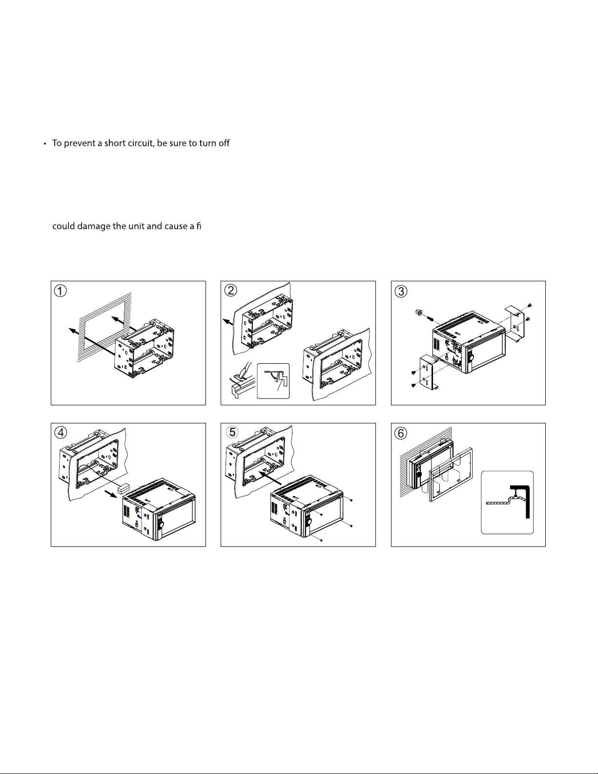
ISO-DIN Installation
Using the Cosmetic Trim Ring
A cosmetic trim ring is supplied with the head unit for installation exibility. This unit will t into most import dashes with little or
no modication to the dash board/cavity. Some US domestic vehicle dashes will accept a Double-DIN chassis, but there is
usually a small gap between the radio and dash piece after installation is complete. In this case, use the trim ring to conceal
any gaps that may be present.
NOTE: For proper operation of the CD/DVD player, the chassis must be mounted within 30° of horizontal. Make sure the unit is
mounted within this limitation.
1
Page 3

Wiring Diagram
CAUTION! IMPOR
or have the installation handled by an experienced technician.
TANT: Incorrect wiring connections can damage the unit. Follow the wiring instructions carefully,
HDMI
-
Black SiriusXM
Black
Black -
RED
ORANGE
BLUE
PINK
GREEN/WHITE
WHITE/PURPLE
WHITE/BROWN
BROWN/BLACK SWC GND
POWER ANT & AMP (+)
BRAKE (-)
REVERSE (+)
SWC A
SWC B
ACC / IGNITION (+)
GPS Antenna (VX7022 Only)
GRAY/BLACK
PURPLE
PURPLE/BLACK
GREEN
GREEN/BLACK
YELLOW
BLACK
RIGHT FRONT SPEAKER (-)
RIGHT REAR SPEAKER (+)
RIGHT REAR SPEAKER (-)
LEFT REAR SPEAKER (+)
LEFT REAR SPEAKER (-)
BATTERY 12V (+)
GROUND (-)
WHITE
WHITE/BLACK
GRAY
RIGHT FRONT
LEFT FRONT SPEAKER (+)
LEFT FRONT SPEAKER (-PEAKER (-)
SPEAKER (+)SPEAKER (+)
SPEAKER (-)
SPEAKER (
)
+)
2
Page 4

2602 Marina Drive, Elkhart, IN 46514
WWW.ASAELECTRONICS.COM
© 2015
Printed in China
 Loading...