

Page 1

User’s Guide
True RMS Digital Multimeter
Model JTM-69A
Page 2

Introduction Jensen 69A
Congratulations on your purchase of Jensen’s JTM-69A true rms Digital
Multimeter. This autoranging meter measures AC/DC Voltage, AC/DC
Current, Resistance, Capacitance, Frequency, Duty Cycle, Temperature,
Diode Test and Continuity. Proper use and care of this meter will provide
many years of reliable service.
Safety
International Safety Symbols
Overvoltage Catagory III
This meter meets the IEC 610-1-95 standard for OVERVOLTAGE
CATEGORY III. Cat III meters are protected against overvoltage
transients in fixed installation at the distribution level. Examples include
switches in the fixed installation and some equipment for industrial use
with permanent connection to the fixed installation.
This symbol, adjacent to another symbol or terminal,
indicates the user must refer to the manual for further
information.
This symbol, adjacent to a terminal, indicates that, under
normal use, hazardous voltages may be present
Double insulation
2
JTM-69A V2.0 10/07
Page 3

Safety Precautions
1. Improper use of this meter can cause damage, shock, injury or
death. Read and understand this user manual before operating the
meter.
2. Make sure any covers or battery doors are properly closed and
secured.
3. Always remove the test leads before replacing the battery or fuses.
4. Inspect the condition of the test leads and the meter itself for any
damage before operating the meter. Repair any damage before
use.
5. Do not exceed the maximum rated input limits.
6. Use great care when making measurements if the voltages are
greater than 25VAC rms or 35VDC. These voltages are considered
a shock hazard.
7. Always discharge capacitors and remove power from the device
under test before performing Capacitance, Diode, Resistance or
Continuity tests.
8. Remove the battery from the meter if the meter is to be stored for
long periods.
9. To avoid electric shock, do not measure AC current on any circuit
whose voltage exceeds 250V AC.
10. Voltage checks on electrical outlets can be difficult and misleading
because of the uncertainty of connection to the electrical contacts.
Other means should be used to ensure that the terminals are not
"live".
Function Maximum Input
V DC, VAC 1000V DC/ 600V AC
Ohms, Capacitance, Diode,
Frequency, Continuity
mA DC/AC 400mA DC/AC
10A DC/AC 10A DC/AC (30seconds max
Input Limits
250V DC/AC
every 15 minutes)
3
JTM-69A V2.0 10/07
Page 4

Specifications
Function Range Resolution Accuracy
DC Voltage
AC Voltage
50/60Hz
DC Current
AC Current
50/60Hz
Resistance
400mV 0.1mV
4V 0.001V
40V 0.01V
400V 0.1V
600V 1V
400mV 0.1mV
4V 0.001V
40V 0.01V
400V 0.1V
600V 1V
400μA 0.1μA
4000μA 1μA
40mA 0.01mA
400mA 0.1mA
10A 0.01A
400μA 0.1μA
4000μA 1μA
40mA 0.01mA
400mA 0.1mA
10A 0.01A
400Ω 0.1Ω ±(1.0% reading + 4 digits)
4kΩ 0.001kΩ ±(1.0% reading + 2 digits)
40kΩ 0.01kΩ
400kΩ 0.1kΩ
4MΩ 0.001MΩ
40MΩ 0.01MΩ ±(2.0% reading + 5 digits)
±(0.5% reading + 2 digits)
±(1.0% reading + 2 digits)
±(1.5% reading + 2 digits)
±(1.0% reading + 70 digits)
±(1.0% reading + 3 digits)
±(1.2% reading + 3 digits)
±(2.0% reading + 4 digits)
±(1.5% reading + 3 digits)
±(2.5% reading + 5 digits)
±(1.8% reading + 5 digits)
±(3.0% reading + 7 digits)
±(1.2% reading + 2 digits)
4
JTM-69A V2.0 10/07
Page 5

Capacitance
4nF 0.001nF
40nF 0.01nF
400nF 0.1nF
4μF 0.001μF
40μF 0.01μF
±(5.0% reading + 10digits)
±(5.0% reading + 7 digits)
±(3.0% reading + 5 digits)
±(3.5% reading + 5 digits)
200μF 0.1μF ±(5.0% reading + 5 digits)
Frequency
9.999Hz 0.001Hz
99.99Hz 0.01Hz
±(1.5% reading + 5 digits)
999.9Hz 0.1Hz
9.999kHz 0.001kHz
99.99kHz 0.01kHz
±(1.2% reading + 2 digits)
999.9kHz 0.1kHz
9.999MHz 0.001MHz
±(1.5% reading + 4 digits)
Sensitivity: 0.8V rms min. @ 20% to 80% duty cycle
and <100kHz; 5Vrms min @ 20% to 80% duty cycle
and > 100kHz.
Function Range Resolution Accuracy
Duty Cycle 0.1 to 99.9% 0.1%
±(1.2% reading + 2 digits)
Pulse width: 100μs - 100ms
Frequency: 5Hz to 150kHz
Temp °F -4 to 1400°F 1°F
Temp °C -20 to 760°C1°C
±(3.0% reading + 3 digits)
(meter only, probe accuracy
not included)
NOTE: Accuracy is stated at 65
o
F to 83oF (18oC to 28oC) and less than
70% RH.
5
JTM-69A V2.0 10/07
Page 6

Diode Test Test current of 0.3mA maximum, open
circuit voltage 1.5V DC typical
Continuity Check Audible signal will sound if the resistance is
less than approximately 30Ω, test current
<0.7mA
Temperature sensor Requires type K thermocouple
Input Impedance 7.5MΩ (VDC and VAC)
AC Bandwidth 40 to 400Hz
Display 4000 count backlit Liquid Crystal
Overrange indication “OL” is displayed
Polarity Automatic (no indication for positive
polarity); Minus (-) sign for negative polarity.
Measurement Rate 2 times per second, nominal
Auto Power Off Meter automatically shuts down after 15
minutes of inactivity
Low Battery Indication “BAT” is displayed if battery voltage drops
below operating voltage
Battery One 9V battery; NEDA 1604, IEC 6F22
Fuses mA, μA and Temperature ranges;
0.5A/250V fast blow
10A range, 10A/250V fast blow
Operating Temperature 32
Storage Temperature -4
o
F to 122oF (0oC to 50oC)
o
F to 140oF (-20oC to 60oC)
Relative Humidity <70% operating, <80% storage
Operating Altitude 7000ft (2000 meters) maximum.
Weight 7 oz. (200g).
Size 6” x 3” x 1.75” (15.25x 7.6x 4.45cm)
Safety For indoor use and in accordance with the
requirements for double insulation to
IEC1010-1 (1995); EN61010-1 (1995)
Overvoltage Category III.
6
JTM-69A V2.0 10/07
Page 7
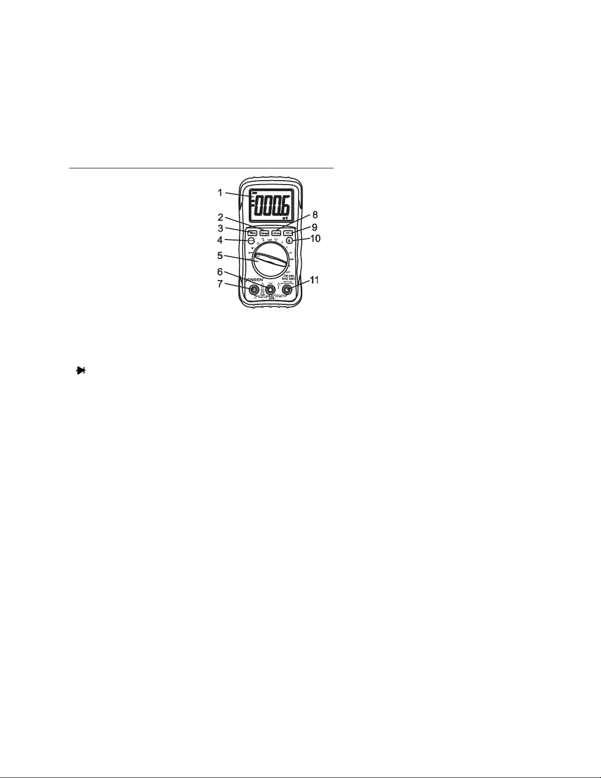
Meter Description
1. Liquid Crystal Display
2. Range button
3. Hz/Duty Cycle button
4. Mode button
5. Rotary Function switch
6. COM jack
7. 10A Current jack
8. Hold button
9. Relative button
10. Backlight button
11. Positive input jack
Note: Tilt stand, fuse and battery compartment are on rear of unit.
Symbols
AC Alternating current or voltage
DC Direct current or voltage
•))) Continuity
Diode test
mV, V millivolt, volt (voltage)
Ω, KΩ, MΩ ohm, kilohm, megohm (resistance)
µA, mA, A microamp, milliamp, Amp (current)
nF, uF nanofarad, microfarad (capacitance)
Hz kHz hertz, kilohertz (frequency)
% % duty cycle
O
F, OC Degrees Fahrenheit, Centigrade (temperature)
AUTO Autorange
BAT Low battery
HOLD Display hold
REL Relative
7
JTM-69A V2.0 10/07
Page 8
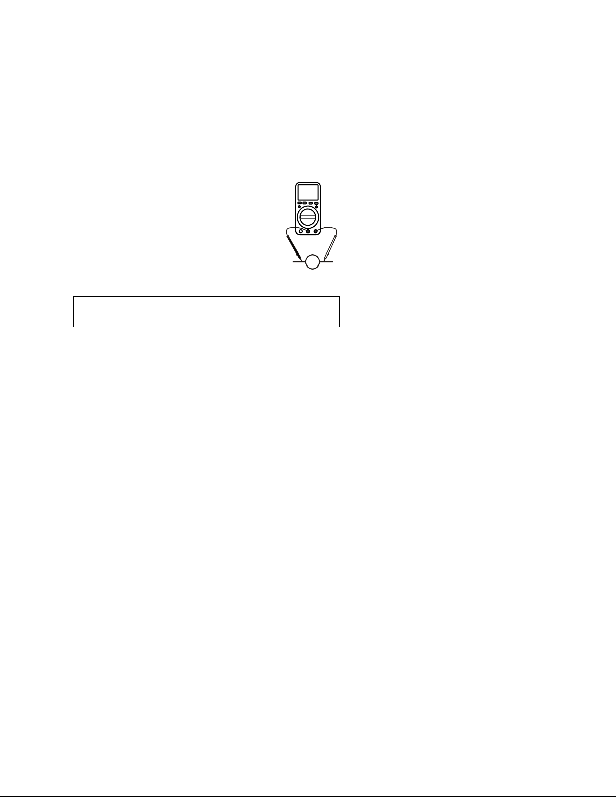
Operating Instructions
V
AC or DC Voltage Measurements
1. Insert the black test lead banana plug into the
negative COM jack and the red test lead banana
plug into the positive V jack.
2. Turn the rotary switch to the VAC or VDC
position.
3. Touch the test probes to the circuit under test
and read the voltage on the display.
Note: Pressing the Hz/% button while in the voltaget
function will switch the display to frequency or d
C Current M
AC or D easurements
CAUTION: Do not make current measurement
longer than 30 seconds every 15 minutes. Exceeding 30 seconds may
cause damage to the meter and/or the test leads.
1. Insert the black test lead banana plug into the negative COM jack
and the red test lead banana plug into the;
a. Positive uA/mA jack for currents to 400m
b. Positive 10A jack for currents to 10A
2. Turn the rotary switch to the uA, mA or A
3. Press the MODE button to select AC or DC current
4. Touch the test probes in series with the circuit under
the current on the display.
Note: Pressing the Hz/% button
the display to frequency or duty cycle
while in the current function will switch
s on the 10A scale for
position.
A
y cycle
ut
test and read
8
JTM-69A V2.0 10/07
Page 9
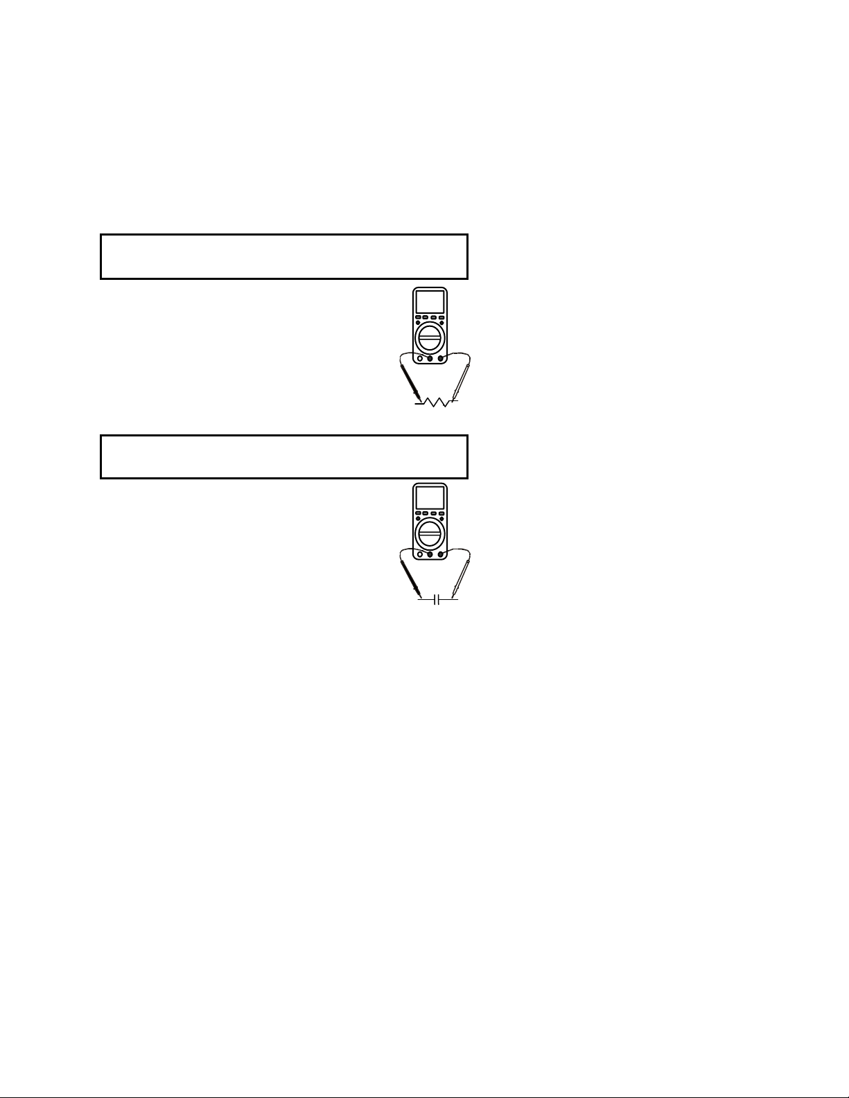
Resistance Measurements
WARNING: To avoid electric shock, disconnect power to the unit
under test and discharge all capacitors before taking any resistance
measurements.
1. Insert the black test lead banana plug into the
negative COM jack and the red test lead banana
plug into the positive Ω jack.
2. Turn the rotary switch to the Ω position.
3. Touch the test probes to the circuit or device
under test and read the resistance on the display.
Capacitance Measurements
WARNING: To avoid electric shock, disconnect power to the unit
under test and discharge all capacitors before taking any capacitance
measurements.
1. Insert the black test lead banana plug into the
negative COM jack and the red test lead banana
plug into the positive CAP jack.
2. Turn the rotary switch to the CAP position.
3. Touch the test probes to the circuit or device
under test and read the capacitance on the
display.
Cap
Ω
9
JTM-69A V2.0 10/07
Page 10
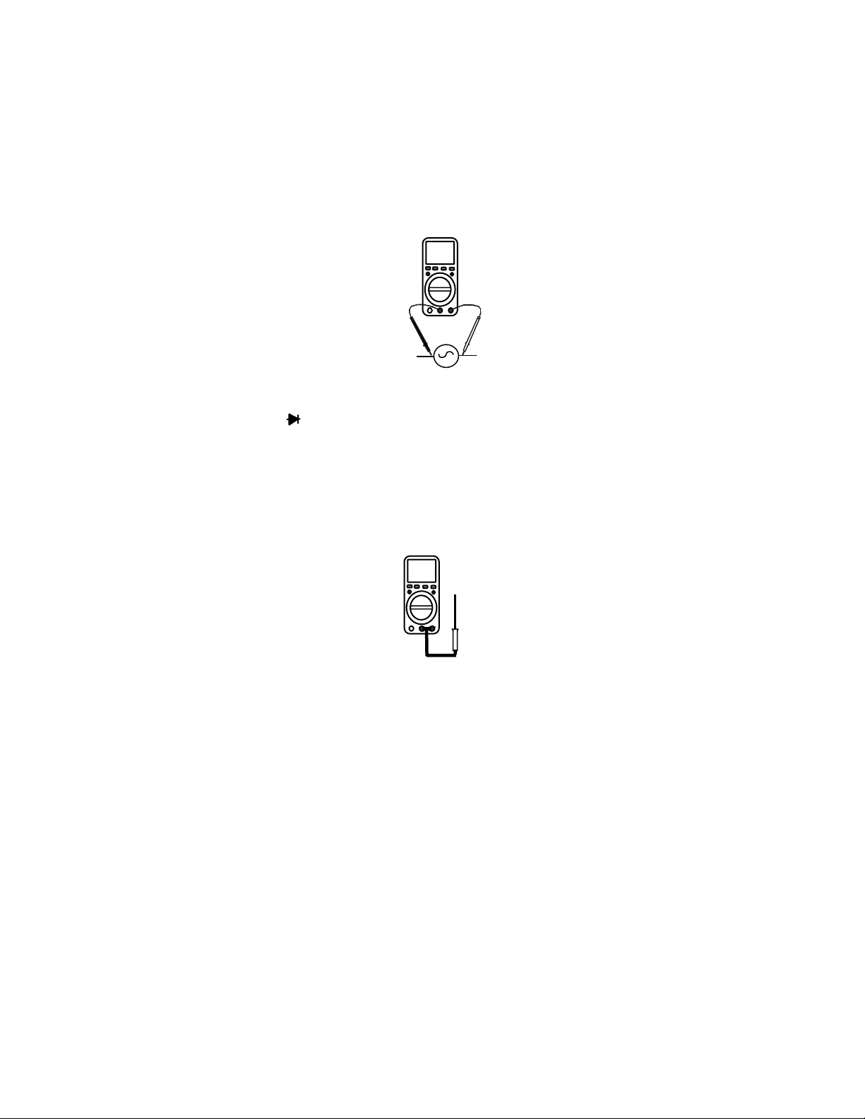
Frequency or Duty Cycle Measurements
1. Insert the black test lead banana plug into the
negative COM jack and the red test lead banana
plug into the positive HZ jack.
2. Turn the rotary switch to the FREQ % position.
3. Press the Hz/% button to select “Hz” or “%”.
4. Touch the test probes to the circuit or under test
and read the frequency or duty cycle on the
display.
Continuity Measurements
1. Insert the black test lead banana plug into the negative COM jack
and the red test lead banana plug into the positive Ω jack.
2. Turn the rotary switch to the •))) position.
3. Press the MODE button until “•)))” appears in the display.
4. Touch the test probes to the circuit or device under test. If the
resistance is less than approximately 30Ω the buzzer will sound
and the resistance appears on the display.
Note: The meter automatically holds the 400Ω range when continuity is
selected
Temperature Measurements
1. Insert the type K thermocouple probe black test
lead banana plug into the negative COM jack and
the red test lead banana plug into the positive
Temp jack..
2. Turn the rotary switch to the
o
C or oF position.
3. Read the temperature on the display.
Hz
10
JTM-69A V2.0 10/07
Page 11

Diode Measurements
1. Insert the black test lead banana plug into the negative COM jack
and the red test lead banana plug into the positive diode jack.
2. Turn the rotary switch to the •))) position.
3. Press the MODE button until “ “ appears in the display.
4. Touch the test probes to the diode under test. Forward voltage will
indicate 0.4V to 0.7V. Reverse voltage will indicate “OL”. Shorted
devices will indicate near 0mV and an open device will indicate
“OL” in both polarities.
Red Black Black Red
Probe Probe Probe Probe
Forward test Reverse test
Manual Ranging
The meter turns on in the autoranging mode. Press the Range button to
go to manual ranging. Each press of the range button will step to the
next range as indicated by the units and decimal point location. Press
and hold the Range button for two seconds to return to autoranging.
Manual ranging does not function in the Capacitance, Frequency and
Temperature functions
Data Hold
Press the Data Hold button to freeze the reading in the display. “HOLD”
will appear in the LCD. Press the button again to release the display.
11
JTM-69A V2.0 10/07
Page 12

Relative Measurements
The relative measurement feature allows you to make measurements
relative to a stored reference value. A reference voltage, current, etc.
can be stored and measurements made in comparison to that value.
The displayed value is the difference between the reference value and
the measured value.
1. Perform any measurement as described in the operating
instructions.
2. Press the Relative button to store the reading in the display and
the "REL" indicator will appear on the display.
3. The display will now indicate the difference between the stored
value and the measured value.
4. Press the Relative button to return to normal operation.
Backlight
The backlight function illuminates the display and is used when the
ambient light to too low to permit viewing of the displayed readings.
Press the button for one second to turn the backlight on and press
the button a second time to turn the backlight off.
Auto Off
The auto off feature will turn the meter off after 15 minutes of inactivity
(Range switch or a button has not been turned or pressed). A beep will
warn the user shortly before the auto off feature activates. Turn the
Function switch to the OFF position and then to a function to resume
operation.
True RMS
The term stands for “Root-Mean-Square,” which represents the method
of calculation of the voltage or current value. Average responding
multimeters are calibrated to read correctly only on sine waves and they
will read inaccurately on non-sine wave or distorted signals. True rms
meters read accurately on either type of signal.
12
JTM-69A V2.0 10/07
Page 13
Maintenance
WARNING: To avoid electric shock, disconnect the test leads from
any source of voltage before removing the battery/fuse cover.
WARNING: To avoid electric shock, do not operate your meter until
the battery/fuse cover is in place and fastened securely.
This Multimeter is designed to provide years of dependable service, if the
following care instructions are performed.
1. Keep the meter dry.
2. Use and store the meter in mild ambient conditions. Temperature
extremes can shorten the life of the electronic parts and distort or
melt plastic parts.
3. Handle the meter gently. Dropping it can damage the electronic
parts or the case.
4. Keep the meter clean. Wipe the case occasionally with a damp
cloth. DO NOT use chemicals, cleaning solvents or detergents.
5. Use only a fresh battery of the recommended size and type.
Remove the old or weak battery so it does not leak and damage
the unit.
6. If the meter is to be stored for a long period of time, the battery
should be removed to prevent damage to the unit.
Battery Replacement
1. Disconnect the test leads from the meter.
2. Remove the rubber holster/boot (if in place).
3. Open the battery door by removing the screws
using a Phillips head screwdriver.
4. Insert the new battery into the battery holder,
observing the correct polarity.
5. Replace the battery door and secure with the
screws.
13
JTM-69A V2.0 10/07
Page 14

Fuse Replacement
WARNING: To avoid electric shock, disconnect the test leads from
any source of voltage before removing battery/fuse cover.
1. Disconnect the test leads from any circuit being measured.
2. Remove the rubber holster (if in place).
3. Open the battery/fuse cover by removing the screws on the rear
using a Phillips screwdriver.
4. Remove the battery cover.
5. Remove the old fuse by gently pulling up on it.
6. Install the new fuse by gently pushing it into the holder.
7. Always use a fuse of the proper size and value (0.5A/250V fast
blow or 10A/250V fast blow).
8. Replace the cover and secure with the screws.
14
JTM-69A V2.0 10/07
Page 15

Warranty
Jensen Tools warrants this instrument to be free of defects in parts and workmanship
for one year from date of shipment (a six month limited warranty applies on sensors
and cables). If it should become necessary to return the instrument for service during
or beyond the warranty period, contact the Customer Service Department at 888-8879473 for authorization. A Return Authorization (RA) number must be issued before
any product is returned to Jensen. The sender is responsible for shipping charges,
freight, insurance and proper packaging to prevent damage in transit. This warranty
does not apply to defects resulting from action of the user such as misuse, improper
wiring, operation outside of specification, improper maintenance or repair, or
unauthorized modification. Jensen specifically disclaims any implied warranties or
merchantability or fitness for a specific purpose and will not be liable for any direct,
indirect, incidental or consequential damages. Jensen 's total liability is limited to
repair or replacement of the product. The warranty set forth above is inclusive and no
other warranty, whether written or oral, is expressed or implied.
Calibration and Repair Services
Jensen offers complete repair and calibration services for the JTM69A.
For periodic calibration, NIST certification or repair of this product, call
customer service for details on services available. Jensen recommends
that calibration be performed on an annual.
www.jensentools.com/about/contact2.cfm?section=techsupport
Technical support: 888-866-5487
Repair & Returns: 888-887-9473
website: www.jensentools.com
15
JTM-69A V2.0 10/07
 Loading...