


JBL SYNTHESIS-DIGITAL ACOUSTIC CALIBRATION SYSTEM, SDEC 1000, SDEC1000A, SDEC 2500, SDEC 2500A Manual
DI G I T A L
AC O U S T I C
CA L I B R A T I O N SY S T E M
(DACS)
♦
IN S T A L L E R 'S MA N U A L

Table of Contents |
|
TABLE OF FIGURES............................................................................................ |
5 |
SECTIION 1 -- IINTRODUCTIION .................................................................................................................................................................. |
.. 7 |
NEED HELP? CALL. . . ............................................................................................ |
7 |
SHIPPING TO THE NEXT DEALER ............................................................................ |
7 |
KIT INVENTORY ................................................................................................. |
9 |
HARDWARE ........................................................................................................... |
9 |
CABLES ................................................................................................................. |
9 |
IF SOMETHING IS MISSING OR DAMAGED ............................................................... |
9 |
SECTIION 2 -- SYSTEM IINSTALLATIION NOTES ........................................................................................................................ |
11 |
SPEAKER PLACEMENT RULES .......................................................................... |
11 |
CENTER MAIN ....................................................................................................... |
11 |
LEFT AND RIGHT MAINS ........................................................................................ |
12 |
SUBWOOFERS ...................................................................................................... |
12 |
SURROUND SPEAKERS ......................................................................................... |
12 |
W A L L MO U N T ......................................................................................................... |
12 |
CE I L I N G MO U N T ...................................................................................................... |
13 |
SYSTEM INTERCONNECTION DIAGRAMS .......................................................... |
14 |
AMPLIFIER AND SDEC SWITCH SETTINGS .............................................................. |
18 |
SECTIION 3 -- PRE--CALIIBRATIION ........................................................................................................................................................ |
19 |
RESTORE PROCESSOR DEFAULT SETTINGS..................................................... |
19 |
SPEAKER PHASE TESTS ................................................................................... |
20 |
ALTERNATE PHASE TEST METHOD ........................................................................ |
20 |
Correct Speaker Phase ................................................................................................ |
21 |
S Y N T H E S I S ON E : .................................................................................................... |
21 |
S Y N T H E S I S TW O : .................................................................................................... |
21 |
S Y N T H E S I S TH R E E : ................................................................................................. |
21 |
Surround Speakers ..................................................................................................... |
21 |
USING THE PHASE TESTER ................................................................................... |
22 |
Cricket -S ................................................................................................................... |
22 |
Cricket -R ................................................................................................................... |
22 |
TEST THE PHASE TESTER ..................................................................................... |
23 |
Sender Test ............................................................................................................... |
23 |
Receiver Test ............................................................................................................ |
23 |
Send -Receive Loop Test .............................................................................................. |
23 |
SOUND CHECK ................................................................................................. |
24 |
SYNTHESIS ONE ................................................................................................... |
24 |
SYNTHESIS TWO & THREE .................................................................................... |
24 |
Confirm Cinem a to Music Mode Change ......................................................................... |
24 |
USING THE SOUND LEVEL METER .................................................................... |
25 |
ANALOG SLM USE INSTRUCTIONS ......................................................................... |
25 |
DIGITAL SLM USE INSTRUCTIONS........................................................................... |
26 |

CORRECTING HUM PROBLEMS.......................................................................... |
27 |
WHAT IS THE ORIGIN OF HUM? ............................................................................. |
27 |
DURING INSTALLATION: ....................................................................................... |
27 |
VIDEO DEVICES: .................................................................................................. |
28 |
SECTIION 4 -- USIING DACS4...................................................................................................................................................................... |
29 |
INTRODUCTION ................................................................................................ |
29 |
ABOUT DATA ACQUISITION ................................................................................... |
29 |
ABOUT DATA PROCESSING ................................................................................... |
30 |
SDEC PROGRAMMING........................................................................................... |
30 |
About Target Curves ................................................................................................... |
30 |
CONNECTING DACS4 TO THE SYSTEM .................................................................. |
31 |
BEST LOCATION FOR THE DACS ANALYZER .......................................................... |
32 |
Power Connections ..................................................................................................... |
32 |
P O W E R I N G -UP TH E DACS S Y S T E M ............................................................................. |
32 |
MI C R O P H O N E P L A C E M E N T ......................................................................................... |
33 |
DACS4 SOFTWARE OPERATION ............................................................................ |
34 |
Custom er Inform ation W indow ...................................................................................... |
35 |
S E L E C T S U R R O U N D P R O C E S S O R ................................................................................. |
36 |
S E L E C T S C R E E N CO M P E N S A T I O N ................................................................................ |
36 |
DACS4 Connection Confirm ation Screen ........................................................................ |
37 |
DACS4 Main Screen Com m unication Fields .................................................................... |
38 |
RE S P O N S E GR A P H c ................................................................................................ |
39 |
FI L T E R S E T T I N G S d ................................................................................................. |
39 |
P R E C I S I O N FI L T E R A D J U S T M E N T e .............................................................................. |
40 |
CH A N N E L A N D MO D E S E L E C T I O N /S T A T U S f ................................................................... |
40 |
P R E V I O U S L Y TE S T E D CH A N N E L OV E R L A Y CO N T R O L g ...................................................... |
41 |
ON L I N E HE L P h ...................................................................................................... |
41 |
Function Keys i ......................................................................................... |
42 |
CH A N N E L GA I N & DE L A Y ........................................................................................... |
42 |
S Y S T E M S T A T U S j .................................................................................................. |
42 |
S T E P - B Y - S T E P C A L I B R A T I O N ................................................................. |
43 |
Auto-Tim e Correction .................................................................................................. |
43 |
Subwoofer Calibration ................................................................................................. |
44 |
RU N A LE V E L TE S T .................................................................................................. |
45 |
RU N A U T O -EQ ....................................................................................................... |
45 |
Left -Center-Right Calibration ........................................................................................ |
46 |
S E T T H E LE V E L ....................................................................................................... |
46 |
A U T O -EQ .............................................................................................................. |
46 |
Surround Calibration ................................................................................................... |
47 |
S E T TH E LE V E L ...................................................................................................... |
47 |
A U T O -EQ .............................................................................................................. |
47 |
Music Mode Calibration ............................................................................................... |
47 |
Quitting DACS4 .......................................................................................................... |
48 |
Test Channel -to -Channel Balance ................................................................................. |
48 |
W H Y US E T H E SLM? ................................................................................................ |
48 |
Quitting Before All Channels Are Accepted ...................................................................... |
49 |
3

SECTIION 5 -- SDEC 1000//2500 ...................................................................................................................................................... |
51 |
INTRODUCTION ................................................................................................ |
51 |
GAIN .................................................................................................................... |
51 |
Test for Optim um Gain ................................................................................................ |
52 |
Determ ine Gain Error - L -C-R and Surrounds .................................................................. |
52 |
Determ ine Gain Error - Subwoofers ............................................................................... |
53 |
SENSITIVITY ......................................................................................................... |
54 |
Test for Optim um Sensitivity ........................................................................................ |
54 |
I F Y O U CA N S E E TH E SDEC DU R I N G TE S T ................................................................... |
55 |
I F Y O U CA N N O T S E E TH E SDEC DU R I N G TE S T .............................................................. |
55 |
MAKING ADJUSTMENTS ......................................................................................... |
57 |
Using the Gain and Attenuation Switches ....................................................................... |
58 |
S W I T C H MA T R I X ..................................................................................................... |
58 |
I N C R E A S I N G GA I N ................................................................................................... |
58 |
RE D U C I N G GA I N ..................................................................................................... |
59 |
RE D U C I N G S E N S I T I V I T Y ............................................................................................ |
59 |
Factory DIP Switch Settings ......................................................................................... |
59 |
LOADER UTILITY .............................................................................................. |
60 |
WINDOWS™ 3.1X .................................................................................................. |
60 |
WIN 95/98™ .......................................................................................................... |
60 |
SECTIION 6 -- DACS2 REFERENCE .................................................................................................................................................... |
61 |
HOOKUP ............................................................................................................... |
61 |
ANALOG EQ/CROSSOVER SYSTEMS ................................................................. |
62 |
SYNTHESIS ONE FACTORY EQ SETTINGS .............................................................. |
62 |
SYNTHESIS ONE CROSSOVER FACTORY SETTINGS................................................ |
63 |
Cinema Mode ............................................................................................................ |
63 |
LOW OUTPUT MUTE: Off (out) ..................................................................................... |
63 |
Music Mode .............................................................................................................. |
64 |
LOW OUTPUT MUTE: OFF (OUT)............................................................................. |
64 |
SYNTHESIS ONE CABLE SPECIFICATIONS .............................................................. |
65 |
SECTIION 7 -- SUBJECTIIVE PERFORMANCE EVALUATIION .............................................................................................. |
67 |
DELOS® TEST CD .............................................................................................. |
67 |
Track 36, Continuous W ide -band Frontal Pan ................................................................. |
67 |
Track 37, Stepped W ide -band Frontal Pan ...................................................................... |
67 |
DELOS® DVD SPECTACULAR ............................................................................ |
67 |
Tracks 10-15, Sine Sweep ........................................................................................... |
67 |
Track 16, Pink Noise, Continuous Pan (5. 1) ................................................................... |
67 |
Tracks 2-5, Dolby™ trailers .......................................................................................... |
67 |
3

FI G U R E FI G U R E FI G U R E FI G U R E FI G U R E FI G U R E FI G U R E FI G U R E FI G U R E FI G U R E FI G U R E FI G U R E FI G U R E FI G U R E FI G U R E FI G U R E FI G U R E FI G U R E FI G U R E FI G U R E FI G U R E FI G U R E FI G U R E FI G U R E FI G U R E FI G U R E FI G U R E FI G U R E FI G U R E FI G U R E FI G U R E FI G U R E FI G U R E FI G U R E FI G U R E FI G U R E FI G U R E FI G U R E FI G U R E FI G U R E FI G U R E FI G U R E FI G U R E FI G U R E FI G U R E FI G U R E
TABL E OF FI GURE S
1: S YN T H E S I S TW O A N D TH R E E CO N T R O L W I R I N G DI A G R A M _______________________________ 14
2:SYN TH E S I S TW O AN D TH R E E IN TE R C O N N E C T W I R I N G DI AG R AM __________________________ 15
3:SYN TH E S I S ON E CO N TR O L W I R I N G DI AG R AM ________________________________________ 16
4:S YN T H E S I S ON E I N T E R C O N N E C T W I R I N G DI A G R A M ____________________________________ 17
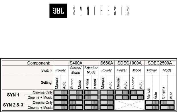
5:CO M P O N E N T S W I T C H S E T T I N G S __________________________________________________ 18
7:GA L A XY A U D I O P H A S E T E S T E R . ___________________________________________________ 22
8:5-P I N DIN T O P H O E N I X A D A P T E R _________________________________________________ 24
9:SLM FA C E P L A T E _____________________________________________________________ 25
10:CO N T R O L LO C A T I O N S _________________________________________________________ 25
11:DI G I T A L SLM _______________________________________________________________ 26
12:S P A T I A L L Y A V E R A G E D S YS T E M R E S P O N S E . _________________________________________ 29
13:TYP I C A L T A R G E T C U R V E _______________________________________________________ 30
14:DACS4 H O O K U P D I A G R A M _____________________________________________________ 31
15:MI C R O P H O N E P L A C E M E N T _____________________________________________________ 33
16:DACS OP E N I N G S C R E E N ______________________________________________________ 34
17:CU S T O M E R I N F O R M A T I O N W I N D O W _______________________________________________ 35
18:CU S T O M E R I N F O R M A T I O N : S E L E C T A S YN T H E S I S MO D E L ______________________________ 36
19:S E L E C T A S U R R O U N D P R O C E S S O R _______________________________________________ 36
20:S E L E C T S C R E E N C O M P E N S A T I O N ________________________________________________ 36
21:DACS4 ON S C R E E N W I R I N G DI A G R A M ____________________________________________ 37
22:DACS4 MA I N S C R E E N ________________________________________________________ 38
23:RE S P O N S E GR A P H W I N D O W ____________________________________________________ 39
24:FI L T E R S E T T I N G A N D CO N T R O L FI E L D ____________________________________________ 39
25:FI L T E R CO N T R O L FI E L D _______________________________________________________ 40
26:DI R E C T CH A N N E L A N D MO D E A C C E S S _____________________________________________ 40
27:CH A N N E L DI S P L A Y CO N T R O L FI E L D ______________________________________________ 41
28:CO N T I N U O U S L Y UP D A T E D ON L I N E HE L P ___________________________________________ 41
29:FU N C T I O N K E YS _____________________________________________________________ 42
30:CH A N N E L GA I N A N D DE L A Y DI A L O G B O X ___________________________________________ 42
31:S YS T E M S T A T U S DE L A Y _______________________________________________________ 42
32:FR E S H I N S T A L L , FI R S T S C R E E N _________________________________________________ 43
33:A U T O -TI M E CO R R E C T I O N DI A L O G B O X ____________________________________________ 43
34:DACS4 R E A D Y F O R S U B W O O F E R L E V E L T E S T _______________________________________ 44
35:LE F T : P R E -EQ R E S P O N S E . RI G H T : P R E -EQ W I T H D I S P L A Y S M O O T H I N G ___________________ 45
36:RE S P O N S E A F T E R A U T O -EQ ____________________________________________________ 45
37:LE F T CI N E M A LE V E L S E T ______________________________________________________ 46
38:A U T O EQ [F3]: A C C E P T S S E T T I N G S . _____________________________________________ 46
39:TYP I C A L S U R R O U N D TA R G E T ___________________________________________________ 47
40:E A R L Y QU I T W A R N I N G S _______________________________________________________ 49
41:SDEC S E N S I T I V I T Y O P T I M I Z A T I O N F L O W C H A R T ______________________________________ 56
42:SDEC GA I N S W I T C H LO C A T O R __________________________________________________ 57
43:B A S I C G A I N / A T T E N U A T I O N S E T T I N G S ______________________________________________ 58
44:S W I T C H MA T R I X _____________________________________________________________ 58
45:DACS2 O N S C R E E N W I R I N G D I A G R A M _____________________________________________ 61
46:S YN T H E S I S ON E F A C T O R Y EQ S E T T I N G S __________________________________________ 62
47:CA B L E DI A G R A M S _____________________________________________________________ 65
SECTION 1 - INTRODUCTION
This document contains reference materials pertaining to the use of the Synthesis Calibration Kits. It is assumed that the reader is experienced in custom home theater installation and has previously received instruction from JBL Synthesis personnel on the use of this equipment.
 Safety related information will be highlighted with this symbol


 Critical information will be highlighted with this symbol

*Important notes and useful tips will be highlighted with this *
SECTIION 1 Look here for general information about the calibration kit and this manual. SECTIION 2 Provides information helpful during system installation.
SECTIION 3 Look here for pre-calibration routines and tests. SECTIION 4 DACS4 short form user's guide.
SECTIION 5 SDEC loader utility, gain and sensitivity control information. SECTIION 6 Analog EQ/Crossover equipped systems are covered here. SECTIION 7 Subjective system performance testing.
N E E D H E L P ? C A L L . . .
If you encounter problems that cannot be resolved using the information presented here, please call your Synthesis Representative for further assistance.
Eric Leicht: 818.830.8705 or 818.259.4189 Chris Neumann: 818.895.5712 or 818.422.1045 Dan Siefert: 805.492.0773
S H I P P I N G T O T H E N E X T D E A L E R
By the time you have completed your Client's installation, you should have received a FAX giving detailed shipping instructions. If you have not received this information, please call immediately and request shipping information.
Unless otherwise instructed, always ship via UPS Blue.
*When shipping, always insure kit for $15,000.00
KI T INV E NT O RY
H A R D W A R E
( 1 ) O p e r a t o r s H a n d b o o k ( 1 ) L a p t o p C o m p u t e r
( 1 ) P h a s e T e s t e r ( t r a n s m i t t e r & r e c e i v e r ) ( 5 ) M i c r o p h o n e s
( 1 ) S p a r e m i c r o p h o n e
( 5 ) T e l e s c o p i c M i c r o p h o n e s t a n c h i o n s ( 5 ) S t a n c h i o n b a s e s
( 1 ) M M X - 5 M i c r o p h o n e M u l t i p l e x e r ( 1 ) S o u n d L e v e l M e t e r
( 1 ) E x t e r n a l V e c t o r P r o c e s s o r ( E V P - 1 ) ( 1 ) E V P - 1 P o w e r S u p p l y
( 1 ) D e l o s S u r r o u n d S p e c t a c u l a r D e m o & T e s t d i s c ( 1 ) D e l o s D V D S p e c t a c u l a r D e m o & T e s t d i s c
( 1 ) T a p e M e a s u r e
C A B L E S
( 5 ) 6 ’ M i c r o p h o n e e x t e n s i o n c a b l e s ( F - X L R t o M - X L R ) ( 1 ) 2 5 ’ S t e r e o a u d i o c a b l e ( R C A t o R C A )
( 1 ) 2 5 ’ M M X - 5 t o l a p t o p c a b l e (T707/T707) or (M-DB9 /T707) or (M-DB9 to M-DB9) ( 1 ) 2 5 ’ C o m p u t e r t o S D E C ( M - D B 9 t o F - D B 9 )
( 1 ) 6 ’ C o m p u t e r t o E V P - 1 ( M - D B 2 5 t o M - D B 2 5 ) ( 1 ) 6 ’ P h a s e t e s t e r a d a p t e r ( F - X L R t o R C A )
( 1 ) 2 5 ’ I n s t r u m e n t a t i o n c a b l e ( B N C t o B N C ) ( 1 ) 2 5 ’ A d a p t e r c a b l e ( B N C t o R C A )
( 1 ) I E C A C p o w e r c o r d
( 1 ) C o m p u t e r A C p o w e r c o r d
( 1 ) M a l e R C A t o t w o f e m a l e R C A " Y " a d a p t e r
I F S O M E T H I N G I S MI S S I N G O R D A M A G E D
If the contents of this kit do not match this list, something is damaged, or the case itself is seriously damaged, contact your Synthesis Representative immediately and arrange for replacement.
Eric Leicht: 818.830.8705 or 818.259.4189
Chris Neumann: 818.895.5712 or 818.422.1045
Dan Siefert: 805.492.0773
3
SECTION 2 - SYSTEM INSTALLATION
NOTES
SP E AKE R PLACE ME NT RULE S
1
 It is vitally important that any speakers mounted above the floor be properly secured! Safety must come first. Never place speakers on a shelf without an approved retaining mechanism. Never screw eye-loops or other hardware directly into speaker cabinets. Unsecured or improperly secured speakers represent a safety hazard which can result in serious injury.
1
The installation of any home theater system represents a balancing of aesthetic and functional requirements which frequently are at odds with each other. The following information should be used to optimize the placement of the speakers and achieve the best results while still conforming to the architectural limitations inherent in the installation.
C E N T E R MA I N
1. If the speaker is behind a perforated screen, place it as far forward as possible, nearly touching the screen.
2. If it is above or below the screen, it must be placed as close as possible to the edge of the screen, along the same plane as the screen.
3. If it is on a shelf, in a pre-fabricated hole in the wall or in a cabinet opening, place it as far forward as possible.
3.1. Any gap around the speaker must be filled. If the gap is ½" closed-cell foam can be used. For gaps greater than ½" it is recommended that you "frame" the speaker with ≈¾" MDF, plywood or other solid panel material.
4. 
 Do not allow anything to obstruct the baffle area of the speakers.
4.1. If decorative cloth is placed in front of the speakers, be sure the frame for the cloth does not obstruct the front of the speaker.
3
L E F T A N D R I G H T MA I N S
1. If the speaker is on a shelf, in a pre-fabricated hole in the wall or in a cabinet opening, place it as far forward as possible.
1.1. Any gap around the speaker must be filled. If the gap is ½" closed-cell foam can be used. For gaps greater than ½" it is recommended that you "frame" the speaker with ≈¾" MDF, plywood or other solid panel material.
2. 
 Do not allow anything to obstruct the baffle area of the speakers.
2.1. If decorative cloth is placed in front of the speakers, be sure the frame for the cloth does not obstruct the front of the speaker.
S U B W O O F E R S
1. In nearly all cases, the best location for subwoofers is on the floor, in the front corners of the room. Place them with the woofers facing the listening area.
1.1. If the subwoofers cannot be placed in the corners, the next best position is on the floor, against the front wall. In this instance, better low frequency coupling may be achieved by turning the subwoofers sideways such that the drivers and ports are next to the front wall.
2. If the subwoofers are placed in a pre-fabricated hole in the wall or in a cabinet opening, place them as far forward (toward the opening) as possible.
2.1. Any gap around the subwoofer must be filled. If the gap is ½" closed-cell foam can be used. For gaps greater than ½" it is recommended that you "frame" the speaker with ≈¾" MDF, plywood or other solid panel material.
2.2. 
 Do not allow anything to obstruct the driver or ports of any speakers.
2.3. If decorative cloth is placed in front of the speakers, be sure the frame for the cloth does not obstruct the driver or ports of the subwoofers.
S U R R O U N D S P E A K E R S
Wall Mount
1. Side surround speakers are to be mounted vertically and placed directly at the sides of the listening area.
2. Rear surround speakers are to be mounted vertically and placed on the rear wall of the listening area.
3. The bottom edge of all surround speakers must be at least 24" above ear level. 3.1. Avoid elevating surround speakers more than 48" above ear level.
4. If the speaker is on a shelf, minimize the width and depth of the shelf as much as possible. 4.1. Place them against the wall.
5. If they are placed in a pre-fabricated hole in the wall or cabinet opening, it must exceed the speaker width by no less than 24".
5.1. Center the speaker in the opening.
5.2. Any open area behind the speaker must be filled to minimize acoustic resonances.
6. 
 Do not allow anything to obstruct the drivers.
6.1. If decorative cloth is placed in front of the speakers, be sure the frame for the cloth does not obstruct the drivers.
3
Ceiling Mount
1
TAKE NO CHANCES!
The mounting hardware provided with Synthesis surround speakers IS NOT suitable for ceiling installation. Improperly suspended speakers represent a serious safety hazard which can result in injury or death.
1
1. Side surround speakers are to be mounted with the top of the enclosure facing the center of the room, as near to the adjacent wall as possible.
2. Rear surround speakers are to be mounted with the top of the enclosure facing the video display screen, as near to the adjacent wall as possible.
3. If they are placed in a pre-fabricated hole or cutout in the ceiling, it must exceed the speaker width by no less than 24".
3.1. Center the speaker in the opening.
3.2. Any open area behind the speaker must be filled to minimize acoustic resonances.
4. 
 Do not allow anything to obstruct the drivers.
4.1. If decorative cloth is placed in front of the speakers, be sure the frame for the cloth does not obstruct the drivers.
3

SY S T E M INTE RCONNE CTI ON DI AG RAM S
Figure 2: Synthesis Two and Three Control Wiring Diagram
3
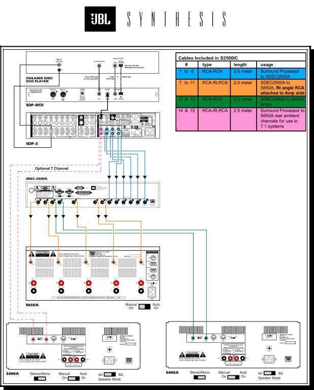
Figure 3: Synthesis Two and Three Interconnect Wiring Diagram
3

Figure 4: Synthesis One Control Wiring Diagram
3
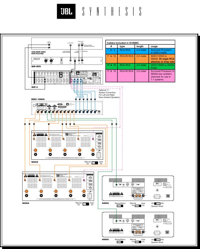
Figure 5: Synthesis One Interconnect Wiring Diagram
3
A M P L I F I E R A N D SDEC S W I T C H S E T T I N G S
Figure 6: Component Switch Settings
3
SECTION 3 - PRE-CALIBRATION
RE S T O RE PROCE S S O R DE F AUL T SE T T I N G S
*This is applicable to all Synthesis models equipped with an SDP-2, SDP-2D or SDP-3 processor.
It is recommended that you restore the Surround Processor to the factory default settings prior to system calibration. This will ensure that you do not waste time later troubleshooting an apparent problem, only to find that the Processor settings were the cause.
1. Use the remote control to turn the processor OFF. 2. Use the remote to turn the processor back ON.
3. Immediately press and hold the MUTE button on the remote control.
4. In a few seconds, the "FACTORY PRESETS MENU" will appear on the Processor's readout. 5. Release the MUTE button.
6. Scroll to and select "RESTORE DEFAULTS".
7. W hen the message "FACTORY DEFAULTS RESTORED" is displayed press DONE to return to normal operation.
Alternatively, you can adjust each setting manually. They should be set as follows:
A. Volume Control: 0dB
B. Speaker Configuration:
LEFT - CENTER – RIGHT: Small, 80Hz high-pass LEFT & RIGHT SIDE: Small dipole, 80Hz high-pass. BASS SPLIT: 80Hz
REARS: None
SUBW OOFER: Yes, Crossover = 80Hz. C. All outputs levels set to 0.0dB
D. SUBW OOFER PEAK LIMITER: OFF E. EQUALIZATION. . .
BASS: 0dB TREBLE: 0dB TILT: 0dB LOUDNESS: OFF
F. LISTENER POSITION: 3’ G. PRO-LOGIC. . .
AUTO AZIMUTH: OFF DIALOGUE ENHANCE: 0dB EFFECT LEVEL: 0dB SUBW OOFER LEVEL: 0dB SURROUND LEVEL: 0dB
H. STEREO BYPASS. . .
SUBW OOFER LEVEL: 0dB
3
 Loading...