

Page 1

ON-BOARD DIAGNOSTICS
V6 and V8 Engine Management
Vehicle Coverage:
X-Type 2.5L V6 and 3.0L V6 2001 model year onwards
X-Type 2.0L V6 2001 model year onwards
S-Type 3.0L V6, 4.2L V8 (normally aspirated and supercharged) from 2002 model year onwards
XK Range 4.2L V8 (normally aspirated and supercharged) from 2003 model year onwards
New XJ 4.2L V8 2003 model year onwards.
Includes Anti-lock Braking System (ABS) monitors from 2004 model year
Jaguar Cars Revision Date: May 2004 Page 1 of 113
Page 2

1 Contents
1
Contents .........................................................................................................................................................................................................................................2
2 OBDII Systems ............................................................................................................................................................................................................................... 6
3 Engine Management System .........................................................................................................................................................................................................7
3.1.1 Fuel Injection....................................................................................................................................................................................................................7
3.1.2 Ignition..............................................................................................................................................................................................................................8
3.1.3 Variable Valve Timing (Normally Aspirated Engines) ......................................................................................................................................................8
3.1.4 Variable Air Intake System (V6 Engines).........................................................................................................................................................................8
3.1.5 Exhaust Gas Recirculation (V8 Engines).........................................................................................................................................................................8
3.1.6 Electronic Throttle Control ...............................................................................................................................................................................................9
3.1.7 Idle Speed Control ...........................................................................................................................................................................................................9
3.1.8 Vehicle Speed Control .....................................................................................................................................................................................................9
4 Sensors and Actuators .................................................................................................................................................................................................................10
5 Mode $06 Data .............................................................................................................................................................................................................................12
6 On Board Monitoring ....................................................................................................................................................................................................................14
6.1 Catalyst Efficiency Monitor....................................................................................................................................................................................................14
6.2 Misfire Monitor.......................................................................................................................................................................................................................18
6.2.1 Misfire Detection ............................................................................................................................................................................................................22
6.3 Heated Oxygen Sensor Monitor............................................................................................................................................................................................27
6.3.1 Downstream Oxygen Sensors High/Low Input Monitor.................................................................................................................................................27
6.3.2 Downstream Oxygen Sensors Heater Circuit High........................................................................................................................................................29
6.3.3 Downstream Oxygen Sensors Heater Circuit Low ........................................................................................................................................................30
6.3.4 Downstream Oxygen Sensors No Activity Detected......................................................................................................................................................30
6.3.5 Upstream Oxygen Sensors Circuit.................................................................................................................................................................................34
6.3.6 Upstream Oxygen Sensors Slow Response..................................................................................................................................................................35
6.3.7 Upstream Oxygen Sensors Heater Circuit.....................................................................................................................................................................36
6.3.8 Control Module...............................................................................................................................................................................................................37
6.4 Fuel System Monitor .............................................................................................................................................................................................................38
6.4.1 Fuel System Secondary Trim.........................................................................................................................................................................................41
6.5 Evaporative Emissions System Monitor................................................................................................................................................................................42
6.5.1 Leak Test Operation ......................................................................................................................................................................................................42
6.6 Fuel Tank Pressure Sensor Circuit .......................................................................................................................................................................................52
6.6.1 High/Low Input Failure ...................................................................................................................................................................................................52
6.6.2 Range/Performance Failure...........................................................................................................................................................................................52
6.7 Exhaust Gas Recirculation System Monitor (V8 Engines)....................................................................................................................................................53
6.7.1 High/Low Input Failure ...................................................................................................................................................................................................53
6.7.2 Exhaust Gas Recirculation Valve Range/Performance Failure .....................................................................................................................................53
Jaguar Cars Revision Date: May 2004 Page 2 of 113
Page 3

Crankshaft/Camshaft Position Sensor ..................................................................................................................................................................................55
6.8
6.8.1 Open and Short Circuit Detection of the Crank Signal ..................................................................................................................................................55
6.8.2 Intermittent Crank Failure Detection ..............................................................................................................................................................................55
6.8.3 Crank Request Signal High Input Monitor .....................................................................................................................................................................55
6.8.4 Open/Short Circuit .........................................................................................................................................................................................................55
6.8.5 Missing Phase Detection ...............................................................................................................................................................................................55
6.9 Mass Airflow Sensor and Manifold Absolute Pressure Sensor............................................................................................................................................. 58
6.9.1 High/Low Input Failure and Ground Monitor..................................................................................................................................................................58
6.9.2 Range/Performance Failure...........................................................................................................................................................................................58
6.10 Barometric Pressure Sensor .............................................................................................................................................................................................64
6.10.1 High/Low Input Failure ...................................................................................................................................................................................................64
6.10.2 Range/Performance Failure...........................................................................................................................................................................................64
6.11 Intake Air Temperature Sensor .........................................................................................................................................................................................65
6.11.1 High/Low Input Failure ...................................................................................................................................................................................................65
6.11.2 Range/Performance Check 1.........................................................................................................................................................................................66
6.11.3 Range/Performance Check 2.........................................................................................................................................................................................66
6.12 Intake Air Temperature Sensor 2 Monitor (V8 Supercharged Only) .................................................................................................................................67
6.12.1 High/Low Input Failure ...................................................................................................................................................................................................67
6.12.2 Range/Performance Check 1.........................................................................................................................................................................................67
6.12.3 Range/Performance Check 2.........................................................................................................................................................................................67
6.12.4 Range/Performance Check 3.........................................................................................................................................................................................67
6.13 Engine Coolant Temperature Sensor ................................................................................................................................................................................68
6.13.1 High/Low Input Failure ...................................................................................................................................................................................................68
6.13.2 Range/Performance Failure...........................................................................................................................................................................................69
6.14 Thermostat Monitor............................................................................................................................................................................................................73
6.15 Throttle Position Sensor ....................................................................................................................................................................................................74
6.16 Engine Oil Temperature Sensor ........................................................................................................................................................................................75
6.16.1 High/Low Input Failure ...................................................................................................................................................................................................75
6.16.2 Range/Performance Failure...........................................................................................................................................................................................75
6.17 Fuel Rail Temperature Sensor ..........................................................................................................................................................................................76
6.17.1 High/Low Input Failure ...................................................................................................................................................................................................76
6.17.2 Range/Performance Failure...........................................................................................................................................................................................76
6.18 Fuel Rail Pressure Sensor.................................................................................................................................................................................................78
6.18.1 High/Low Input Failure ...................................................................................................................................................................................................78
6.18.2 Stuck Detection ..............................................................................................................................................................................................................78
6.18.3 Offset Detection .............................................................................................................................................................................................................78
6.19 Fuel Injectors .....................................................................................................................................................................................................................80
6.20 Fuel Pumps........................................................................................................................................................................................................................81
6.20.1 Primary Fuel Pump - No Commands Received.............................................................................................................................................................81
Jaguar Cars Revision Date: May 2004 Page 3 of 113
Page 4

Primary Fuel Pump - Not Working When Requested ....................................................................................................................................................81
6.20.2
6.20.3 Primary Fuel Pump Circuit High/Low Fault....................................................................................................................................................................81
6.20.4 Secondary Fuel Pump Monitor ......................................................................................................................................................................................83
6.21 Fuel Level Sensor.............................................................................................................................................................................................................. 84
6.21.1 Fuel Level Stuck Monitor ...............................................................................................................................................................................................84
6.21.2 Fuel Level Noisy Monitor ...............................................................................................................................................................................................84
6.22 Knock Sensor ....................................................................................................................................................................................................................85
6.22.1 High/Low Input Failure ...................................................................................................................................................................................................85
6.22.2 Knock Sensor Processor Failure ...................................................................................................................................................................................86
6.23 Variable Valve Timing........................................................................................................................................................................................................86
6.24 Ignition Amplifiers/Coils .....................................................................................................................................................................................................88
6.25 Charge Air Cooler Water Pump.........................................................................................................................................................................................89
6.26 Idle Speed Control.............................................................................................................................................................................................................90
6.27 Starter Relay...................................................................................................................................................................................................................... 92
6.28 Air Conditioning Clutch Relay............................................................................................................................................................................................92
6.29 Park/Neutral Switch ........................................................................................................................................................................................................... 93
6.30 Accelerator Pedal Position Sensor Monitor.......................................................................................................................................................................94
6.31 Throttle Control..................................................................................................................................................................................................................95
6.31.1 Sensor Power Supply Monitor .......................................................................................................................................................................................95
6.31.2 Analogue Ground Monitor..............................................................................................................................................................................................95
6.31.3 Throttle Actuator Control Monitor................................................................................................................................................................................... 96
6.31.4 Throttle Motor Relay Monitor .........................................................................................................................................................................................96
6.31.5 Throttle Motor Relay Driver Monitor............................................................................................................................................................................... 96
6.31.6 Throttle Return Spring Monitor.......................................................................................................................................................................................97
6.31.7 Throttle Limp Home Spring Monitor...............................................................................................................................................................................97
6.31.8 Throttle Watchdog Monitor.............................................................................................................................................................................................97
6.32 Intake Manifold Tuning Valve System .............................................................................................................................................................................101
6.33 Generator Monitor............................................................................................................................................................................................................101
6.33.1 Generator Charge Line Monitor (V6 Only)...................................................................................................................................................................101
6.33.2 Generator Field Line Failure (V6 Only)........................................................................................................................................................................101
6.33.3 Charging System/Generator Load Failure ...................................................................................................................................................................101
6.34 Engine Control Module ....................................................................................................................................................................................................102
6.34.1 ECM Control Relay Monitor .........................................................................................................................................................................................103
6.34.2 Main Processor Monitor ...............................................................................................................................................................................................103
6.34.3 Sub Processor Monitor ................................................................................................................................................................................................103
6.34.4 Battery Back Up Monitor ..............................................................................................................................................................................................103
6.34.5 Processor Communications Monitor ............................................................................................................................................................................104
6.34.6 Engine Control Module Keep Alive Memory Monitor...................................................................................................................................................104
6.35 Communications Network Monitors.................................................................................................................................................................................107
Jaguar Cars Revision Date: May 2004 Page 4 of 113
Page 5

Anti-lock Braking System System ..............................................................................................................................................................................................108
7
7.1 Wheel Speed Sensors ........................................................................................................................................................................................................108
7.1.1 Wheel Speed Sensor Monitoring (XJ Range, XK Range and S-Type)........................................................................................................................108
7.1.2 Wheel Speed Sensor Monitoring (X-Type) ..................................................................................................................................................................111
7.2 Control Module Failure........................................................................................................................................................................................................113
Jaguar Cars Revision Date: May 2004 Page 5 of 113
Page 6

2 OBDII Systems
California On-Board Diagnostics II (OBD) applies to all gasoline engine vehicles up to 14,000 lbs. Gross Vehicle Weight Rating (GVWR) starting in the 1996
model year and all diesel engine vehicles up to 14,000 lbs. GVWR starting in the 1997 model year.
"Green States" are states in the Northeast that chose to adopt California emission regulations, starting in the 1998 model year. At this time, Massachusetts, New
York, Vermont and Maine are Green States. Green States receive California certified vehicles for passenger cars and light trucks up to 6,000 lbs. GVWR.
The National Low Emissions Vehicle program (NLEV) requires compliance with California OBDII, including 0.020" Evaporative Emissions (EVAP) system
monitoring requirements. The NLEV program applies to passenger cars and light trucks up to 6,000 lbs. GVWR nationwide from 2001 model year through 2003
model year.
Federal OBD applies to all gasoline engine vehicles up to 8,500 lbs. GVWR starting in the 1996 model year and all diesel engine vehicles up to 8,500 lbs. GVWR
starting in the 1997 model year.
OBDII system implementation and operation is described in the remainder of this document.
Jaguar Cars Revision Date: May 2004 Page 6 of 113
Page 7

3 Engine Management System
The Engine Control Module (ECM) controls the engine management system. The system consists of an ECM and a number of sensing and actuating devices.
The sensors supply the ECM with input signals, which relate to engine operating conditions and driver requirements. The ECM uses calibrated data-tables and
maps to evaluate the sensor information. The ECM then uses the results to command an appropriate response from the actuating devices. The system provides
the necessary engine control accuracy and adaptability to:
• Minimize exhaust emissions and fuel consumption.
• Provide optimum driver control under all conditions.
• Minimize evaporative fuel emissions.
• Provide system diagnostics when malfunctions occur.
In addition to these functions the ECM also interfaces with other vehicle systems through the Controller Area Network (CAN) communications network.
The 32-bit ECM is at the center of the system and provides the overall control. Its functions are listed below, each of which are dependent on the engine and
vehicle state at any moment of time and driver requirements.
• Starting: Ensures that conditions are safe to crank the engine.
• Engine: Controls the rate of air and fuel flow into the cylinders; adjusts the intake manifold volume; controls the ignition and intake camshaft timing.
• Fuel supply: Controls the operation of the fuel pumps and the EVAP canister purge valve.
• Cooling: Controls the engine cooling fans.
• Battery: Optimizes the battery charging conditions.
• Air Conditioning (A/C) and screen heater: Controls the speed of the engine when these additional loads are added, also disables the A/C when it is
beneficial to reduce the load on the engine.
• Speed control: Provides the option to maintain a fixed vehicle speed without driver intervention.
• Robustness: Maintains engine running condition under intermittent or permanent single point failures on any sensors or actuators fitted to the system,
and records Diagnostic Trouble Codes (DTCs) of these failures for system diagnosis.
• Diagnosis: Notifies the driver when a system malfunction occurs and records data for system diagnosis.
3.1.1 Fuel Injection
The ECM controls one injector per cylinder in sequential operation. The size of the injector used is so that stoichiometric control is possible at minimum load with
allowance for EVAP canister purge valve correction, and at maximum load to provide sufficient fuel flow at all engine speeds. The timing of injector firing, relative
to intake valve closing, during normal starting and running conditions is optimized to provide the best compromise between emissions and performance, time to
first-ignition and smooth engine operation at start-up, for all engine conditions at all temperatures. The mass of fuel per-injection is derived from a calculation
based on a ratiometric match to the metered airflow.
Jaguar Cars Revision Date: May 2004 Page 7 of 113
Page 8

The ECM is capable of adapting to fuel system tolerances and engine internal wear under all operating conditions. The ECM continually monitors the differential
pressure between the fuel rail and plenum, and uses this value to calculate the injector pulse width with the required mass of fuel per-injection. The ECM also
continually monitors the temperature of the fuel being injected into the engine and provides compensation for the changing flow characteristics of the fuel system
at different temperatures. By monitoring the battery supply voltage the ECM can ensure that the fuel supply to the engine is unaffected by voltage fluctuation.
3.1.2 Ignition
The system uses one ignition coil per-cylinder. A base ignition map is provided so that the engine can be optimized for emissions, fuel economy, performance
and avoidance of cylinder knock throughout its speed and load range. Ignition timing during starting is used during engine cranking and under speed modes to
provide the best compromise between emissions, time to first ignition and smooth engine operation at start up, at all temperatures. Provision is made to
compensate for the effect of changing air intake temperature on the combustion detonation limit. The system contains the necessary hardware for the detection
of combustion knock within the engine cylinders; the ECM uses this information to gradually adjust the ignition timing until the combustion knock is at a safe and
inaudible level.
3.1.3 Variable Valve Timing (Normally Aspirated Engines)
The ECM controls the fully variable phase change system, which acts on the intake camshafts. The target positions of both camshafts are optimized to provide
the best compromise between performance, refinement, fuel economy and emissions. During transient operation, the rate of change of the Camshaft Position
(CMP) is controlled to optimize drivability. Operation of the Variable Valve Timing (VVT) will be restricted if environmental conditions exist that could affect
normal operation of the VVT, for example very low ambient temperatures. Provision is made to ensure that the intake camshafts are restrained in the retard
position during engine start. The ECM will also detect a variable valve timing mechanical malfunction, and act to compensate for the malfunction.
3.1.4 Variable Air Intake System (V6 Engines)
The ECM controls two intake manifold tuning valves. Each valve is a two positional device; the switching point of the valve is dependant on engine speed and a
definable change in engine performance. The valve switching points are optimized for maximum torque in the wide-open Throttle Position (TP).
3.1.5 Exhaust Gas Recirculation (V8 Engines)
The ECM controls the flow of exhaust gases to reduce oxides of nitrogen in emissions by re-circulating metered amounts of exhaust gas into the intake of the
engine. This lowers the combustion temperature, limiting the formation of nitrogen oxides. The Exhaust Gas Recirculation (EGR) flow is optimized for fuel
economy, emissions and drivability for all engine-operating conditions.
Jaguar Cars Revision Date: May 2004 Page 8 of 113
Page 9

3.1.6 Electronic Throttle Control
The electronic throttle controls the airflow into the engine under closed loop feedback control of the ECM. The correct throttle disc position is calculated as a
function of driver demand and of the engine's momentary operating mode. A fail safe system is incorporated that complies with legislative requirements, including
mechanical limp-home operation.
3.1.7 Idle Speed Control
Idle speed is dependent on Engine Coolant Temperature (ECT) and gear selection (neutral or drive). Idle speed is optimized for combustion stability, idle quality,
Idle Speed Control (ISC) capability and fuel economy at all operating conditions. Compensations to the idle speed will be made for conditions, such as variable
ambient air temperature, to increase idle speed to satisfy charging system requirements.
3.1.8 Vehicle Speed Control
The engine management system incorporates a speed control system. This enables the driver to set a speed, and control and maintain the speed of the vehicle
without having to operate the accelerator pedal. The speed control switches are momentary action switches, mounted on the steering wheel. The function of the
switches is organized so that a function relating to a switch of higher priority always overrides a function relating to a lower priority switch. The switch priority is:
• 1. Cancel
• 2. Set
• 3. Resume
Jaguar Cars Revision Date: May 2004 Page 9 of 113
Page 10
4 Sensors and Actuators
The following table defines the function of the engine mounted sensors and actuators:
Component Function
Fuel injectors Delivers fuel to the engine cylinder intake ports in sequential order. There are 12 fuel injection holes per cylinder,
delivering fuel droplets as small as 60 microns in diameter. This size of fuel droplet reduces fuel wetting of the intake port
and promotes excellent fuel air mixing. Reducing noxious emissions and improving fuel economy while the engine is
warming up.
On-plug ignition coil The ECM controls one coil per spark plug in sequential order. The ignition coil provides the energy to the spark plug to
ignite the air fuel mixture in the engine cylinder. The ignition coil works on the principle of 'mutual induction'. By closing and
then opening the ignition coil primary circuit, the primary current increases, and then suddenly decreases to induce the
high voltage in the secondary circuit needed to fire the spark plug.
CMP sensor Signals from the CMP sensors are used to synchronize the ECM to the engine cycle during engine starting. For example,
whether the Crankshaft Position (CKP) sensor is indicating an induction or firing stroke. The position of both intake
camshafts is monitored to allow the ECM to control the phase of the intake camshafts relative to the position of the
crankshaft. On engines with VVT, the CMP sensor provides feedback control on the intake camshaft's position relative to
the position of the crankshaft and exhaust camshafts.
Oil control solenoid - VVT
(normally aspirated engines)
Manifold Absolute Pressure
(MAP) sensor
Knock sensor The knock sensors produce a voltage signal with respect to the engine's combustion level. The knock sensor detects and
Fuel rail pressure sensor Continuously monitors the fuel pressure between the fuel rail and plenum, this value is used by the ECM as one of its
Fuel rail temperature sensor The fuel rail temperature sensor continuously monitors the temperature of fuel being injected into the engine; this value is
Intake manifold tuning valves (V6
engines)
Jaguar Cars Revision Date: May 2004 Page 10 of 113
The oil control solenoid is a hydraulic actuator, which advances and retards the intake camshaft timing, thereby altering
the camshaft-to-crankshaft phasing.
The manifold absolute pressure sensor is used for EGR diagnostic testing only.
reports combustion knock within the engine cylinders. The ECM uses this information to gradually adjust the ignition timing
until the combustion knock is at a safe and inaudible level. The knock control system cannot advance the ignition past the
mapped values; it retards the ignition timing to reduce combustion knock and then advances to its original value.
factors to calculate the injector pulse-width required to deliver the correct mass of fuel per injection. The ECM also uses
this information to demand a specific fuel flow rate from the fuel pump via the fuel pump module.
used by the ECM to provide compensation for the changing flow characteristics of the fuel system with temperature. The
ECM therefore ensures that engine performance is unaffected by temperature changes in the fuel supply.
The intake manifold tuning valves are a two positional 'open or close' device used to create a variable air intake system.
The intake manifold tuning valve positions are switched, via signals from the ECM, to optimize torque across the engine
speed and load range. The intake manifold tuning valves work in conjunction with the operation of the throttle body
sensors.
Page 11
Component Function
Throttle body assembly The throttle body controls the airflow into the engine by use of the throttle motor and TP sensor. Throttle-disc position is
operated by the throttle motor using signals received from the Accelerator Pedal Position (APP) sensor, via the ECM. The
ECM, via the TP sensor, monitors throttle disc angle. The ECM on application of external loads, for example the A/C
compressor, makes compensation to the throttle disc angle.
Mass Airflow (MAF) sensor with
integrated Intake Air Temperature
(IAT) sensor
CKP sensor The CKP sensor is an inductive pulse generator, which scans protrusions on a pulse ring, to inform the ECM of the
ECT sensor The thermistor type sensor provides an input signal to the ECM, which is proportional to the temperature of the engine
Engine Oil Temperature (EOT)
sensor
Heated Oxygen Sensor (HO2S) 1 The HO2S 1 is a linear characteristic type sensor, fitted forward of the exhaust system's catalytic converter. The sensor is
HO2S 2 The HO2S 2 is a non-linear characteristic type sensor fitted to the exhaust system's catalytic converter, and is used by the
EGR valve A defined portion of the engine's exhaust emissions is extracted and returned to the intake mixture via a solenoid valve, as
Air intake control flap solenoid
(S/C engine)
Engine oil pressure switch This switch is connected to the Instrument Pack (IPK) and is used for a low oil pressure warning. It is not used by the
The MAF sensor informs the ECM of the rate of airflow entering the engine by producing a voltage, which increases as the
rate of airflow increases. The MAF sensor also takes into account the density of air entering the engine so it is possible to
maintain the required air fuel ratio, and compensate for variations in atmospheric pressure and temperatures. The integral
IAT sensor measures the temperature of the air entering the intake system. The ECM uses this information to compensate
for higher than normal IAT upon combustion detonation.
crankshaft's position and engine speed.
coolant being circulated around the coolant system.
The thermistor type sensor provides an input signal to the ECM, which is proportional to the temperature of the oil being
circulated around the engine oil passageways.
used by the ECM as a primary sensor to measure oxygen content within the exhaust system. The sensor is used in
conjunction with the ECM to provide closed loop fuelling control.
ECM as a secondary sensor to measure oxygen content within the exhaust system. Used in conjunction with the ECM and
the HO2S 1, the HO2S 2 aids closed loop fuelling control. It is also used to monitor catalyst efficiency.
controlled by the ECM.
The ECM directly controls the solenoid, to open and close the air intake control flap in the air cleaner assembly. The
control flap is opened at high engine speed and loads to satisfy engine air charge requirements.
engine management system.
Jaguar Cars Revision Date: May 2004 Page 11 of 113
Page 12
5 Mode $06 Data
SAE J1979 Mode $06 Data
Test ID Comp ID Description Units
$02 $00 Catalyst system efficiency below threshold 1 - bank (delay time) msec
$04 $00 Catalyst system efficiency below threshold 2 - bank (delay time) msec
Conversion for TID $02 and $04: Multiply by 4 to get result in milliseconds.
$06 $00 EVAP system leak detected (20 thou) kPa
$07 $00 EVAP system leak detected (gross leak) kPa
$08 $00 EVAP system leak detected (40 thou) kPa
Conversion for TID $06 and $08: Multiply by 6.25/1024, then subtract 4.125 to get result in kPa.
Conversion for TID $07: Multiply by 6.25/1024 to get result in kPa.
$09 $00 EGR system flow malfunction (GA changing rate low) g/sec
$0A $00 EGR system flow malfunction (GA changing rate high) g/sec
Conversion for TID $09 and $0A: Multiply by 400/65536, then subtract 200 to get result in g/sec. Result can be positive or negative.
$0B $00 EVAP system flow check None
$0C $00 EVAP system flow check None
Conversion for TID $0B and $0C: Multiply by 0.5/65536.
$0D $00 EVAP system flow check None
$0E $00 EVAP system flow check None
Conversion for TID $0D and $0E: Multiply by 2/65536.
$0F $00 EVAP system flow check rpm
$10 $00 EVAP system flow check rpm
$11 $00 EVAP system flow check rpm
Conversion for TID $0F, $10 and $11: Multiply by 100/256 to get result in RPM.
$12 $00 EVAP system flow check g/sec
Conversion for TID $12: Multiply by 1/1024 to get result in g/sec.
$13 $00 Catalyst system efficiency below threshold 1 - bank (high airflow) None
$14 $00 Catalyst system efficiency below threshold 2 - bank (high airflow) None
Conversion for TID $13 and $14: Multiply by 1.25/256
$1A $00 Upstream HO2S 11 lean to rich response time counter msec
$1B $00 Upstream HO2S 21 lean to rich response time counter msec
Conversion for TID $1A and $1B: Multiply by 64 to get result in msec.
Jaguar Cars Revision Date: May 2004 Page 12 of 113
Page 13
SAE J1979 Mode $06 Data – Continued
$1C $00 Upstream HO2S 11 minimum sensor current for test cycle mA
$1D $00 Upstream HO2S 21 minimum sensor current for test cycle mA
$1E $00 Upstream HO2S 11 maximum sensor current for test cycle mA
$1F $00 Upstream HO2S 21 maximum sensor current for test cycle mA
Conversion for TID $1C, $1D, $1E and $1F: Multiply by 1/256, then subtract 128 to get result in mA. Result can be positive or negative.
$21 $00 EGR system flow malfunction (MAP changing rate low) kPa
$22 $00 EGR system flow malfunction (MAP changing rate high) kPa
Conversion for TID $21 and $22: Multiply by 500/65536, then subtract 133.35 to get result in kPa. Result can be positive or negative.
Jaguar Cars Revision Date: May 2004 Page 13 of 113
Page 14

6 On Board Monitoring
The vehicle drive train is continually monitored throughout its life to maintain its proper function and ensure that emission levels do not exceed accepted limits.
6.1 Catalyst Efficiency Monitor
Catalytic converters oxidize unburned Hydrocarbons (HC) and Carbon Monoxide (CO) by combining them with oxygen to produce water vapor, and reduce
nitrogen oxides to nitrogen and oxygen. When the engine air fuel ratio is lean, the oxygen content of the catalytic converter reaches its maximum value. When
the air fuel ratio is rich, the oxygen content is depleted. If the air fuel ratio remains rich for an extended period, the converter may fail to convert the harmful
gases.
The Catalyst monitor operates once per trip, and is not a continuous monitor.
The monitor waits until all entry conditions are met, including the modeled catalyst temperature reaching its threshold. Once all entry conditions are met, the
monitor starts to run. The fuelling is cycled rich and lean (called dither) by approximately 3% to get a reaction at the downstream Oxygen Sensor (O2S). At the
start of the monitor, delay counters operate so that the fuelling is stable when the diagnosis takes place. If the entry conditions then drop out, the monitor result
and execution timer are held at the values that they were when the entry conditions dropped out. The next time entry conditions are met the monitor carries on
from where it stopped previously. This will happen for a maximum of four attempts, after this, the monitor will reset and the diagnosis restarts.
The monitor runs for a calibratable period of time, after which the monitor results are made. The monitor results are decided by accumulating the locus of the
downstream O2S signal versus the accumulation of the upstream O2S. The more active the downstream sensor, the less oxygen storage capacity the catalyst
has, so the higher the locus value.
With a 100,000-mile catalyst, the downstream O2S is not so active, so lower locus values are obtained.
A judgment is made when the monitor has finished. The judgment made can either be "normal" or "fail". The normal judgment is made if the accumulated count
is lower than a calibratable threshold at the judgment point. The failure judgment is made if the accumulated count equals or exceeds the calibratable threshold
at the judgment point. If a failure judgment is made, then the relevant DTCs are stored within the engine management system.
Jaguar Cars Revision Date: May 2004 Page 14 of 113
Page 15
A
A
A
A
A
A
Note: Unless specifically included in the tables below, IAT, ECT, vehicle speed and time after start up are not critical to enable these monitors.
Catalyst Monitor Operation – Up to 2004 Model Year
Strategy DTCs Description Malfunction Criteria Value Secondary Parameter Enable
Conditions
Catalyst
efficiency bank
1
Catalyst
efficiency bank
2
Disable: P0101, P0102, P0103, P0104, P0106,
Bank 1 P0031, P0032, P0037, P0038, P0137,
P0420 Ratio of locus of upstream/
downstream HO2S during
mixture dither.
P0430 IAT
ccumulative locus of
downstream sensor
> 17 Engine speed
Closed lop fuelling
ECT
irflow
tmospheric pressure
irflow change
Engine speed change
Throttle angle change
Idle
Sub feedback compensation
ir fuel ratio compensation
Linear air fuel ratio
compensation
Fuel level
1300 to 3000 RPM
ctive
75 to 120 °C
-20 to 110 °C
14 to 65 g/s
> 70.0 kPa
< 30 g/s/s
< 360 RPM/s
< 10 deg/s
Inactive
0.9 to 1.1
0.75 to 1.25
0.5 to 1.5
> 11%
P0107, P0108, P0111, P0112, P0113,
P0116, P0117, P0118, P0121, P0122,
P0123, P0125, P0128, P0222, P0223,
P0301, P0302, P0303, P0304, P0305,
P0306, P0307, P0308, P0443, P0444,
P0445, P0460, P0603, P1224, P1229,
P1251, P1313, P1314, P1316, P1367,
P1368, P1609, P1611, P1631, P1633,
P1637, P1642, P1215, P1216, P1344,
P1234, P1236, P1338, P3029
P0138, P0140, P0171, P0172, P0201,
P0203, P0205, P0207, P0351, P0353,
P0355, P0357
Time
Required
30s
2 DTC
2 DTC
MIL
Jaguar Cars Revision Date: May 2004 Page 15 of 113
Page 16

A
A
A
A
Catalyst Monitor Operation – From 2004 Model Year
Strategy DTCs Description Malfunction Criteria Value Secondary Parameter Enable Conditions Time
Bank 2 P0051, P0052, P0057, P0058, P0157,
P0158, P0160, P0174, P0175, P0202,
P0204, P0206, P0208, P0352, P0354,
P0356, P0358
Catalyst
efficiency bank
1
Catalyst
efficiency bank
2
P0420 Ratio of locus of upstream/
downstream HO2S during
mixture dither.
P0430 IAT
ccumulative locus of
downstream sensor
>=14 (X-Type)
>= 16 (XK8)
>= 17 (XJ)
>= 18 (V6 SType)
Engine speed (RPM)
Closed loop fuelling
ECT
MAF
tmospheric pressure
irflow change
Engine speed change
Throttle angle change
Idle
Sub feedback control
Short term fuel trim
Total fuel trim
Fuel level
1300 to 2900 (X-Type)
1300 to 3000 (V8)
1300 to 3250 (V6 SType)
ctive
75 to 119 °C
-20 to 101 °C
-8.13 to 110 °C (XType)
10 to 65 g/s
10 to 40 g/s (X-Type)
>= 70.0 kPa
>= 75.5 kPa (X-Type
<= 30 g/s/0.512s
<=20 g/s/0.512s (XType)
<= 360 RPM/0.512s
<= 10 deg/1.024s
Inactive
0.9 to 1.1
0.75 to 1.25
0.5 to 1.5
>= 11%
30s
20s (X-Type)
2 DTC
MIL
Required
2 DTC
Jaguar Cars Revision Date: May 2004 Page 16 of 113
Page 17

Catalyst Monitor Operation – From 2004 Model Year - Continued
Strategy DTCs Description Malfunction Criteria Value Secondary parameter Enable Conditions Time
Required
Disable: C1137, C1145, C1155, C1165,
C1175, P0101, P0102, P0103,
P0106, P0107, P0108, P0111,
P0112, P0113, P0116, P0117,
P0118, P0121, P0122, P0123,
P0125, P0128, P0181, P0182,
P0183, P0191, P0192, P0193,
P0222, P0223, P0441, P0443,
P0444, P0445, P0460, P0603,
P1104, P1224, P1229, P1233,
P1234, P1236, P1251, P1313,
P1314, P1316, P1338, P1339,
P1367, P1368, P1609, P1611,
P1631, P1633, P1637, P1642
Bank 1 P0031, P0032, P0037, P0038,
P0133, P0137, P0138, P0140,
P0171, P0172, P0201, P0203,
P0205, P0207, P0351, P0353,
P0355, P0357
Bank 2 P0051, P0052, P0057, P0058,
P0153, P0157, P0158, P0160,
P0174, P0175, P0202, P0204,
P0206, P0208, P0352, P0354,
P0356, P0358
Disable Additions: P0069, P0607, P0627, P0628,
P0629, P2118, P2119, P2135,
P2228, P2229, P2632, P2633,
P2634, P2635, P2636
MIL
2
DTC
2
DTC
2
DTC
2
DTC
Jaguar Cars Revision Date: May 2004 Page 17 of 113
Page 18

6.2 Misfire Monitor
A misfire is caused by a failure of combustion. When this occurs, unburned HC and excess oxygen are exhausted from the cylinder. Consequently, the catalytic
converter may suffer damage through overheating as it tries to convert the excessive HC. Secondly, the O2S will report a lean condition to the ECM, which in
turn will increase the injector pulse width and add more raw fuel to the exhaust stream.
The misfire detection monitor is continuous and is designed to detect levels of misfire that can cause thermal damage to the catalyst and/or result in excessive
tailpipe emissions. Determination of a misfire is made by analysis of changes in crankshaft speed, a misfire causing a drop in acceleration after an anticipated
firing event. This data is analyzed in four ways to ensure all possible combinations of misfire can be detected.
The results of the misfire judgment process on each firing event are used to determine whether two failure levels have been met, 'catalyst damage' misfire and
'excess emissions' misfire. Each fault judgment process has its own failure threshold and calculation period.
Monitor DTCs
P0300 Random/multiple cylinder misfire
P0301 Cylinder 1 (1 bank 1) misfire
P0302 Cylinder 2 (1 bank 2) misfire
P0303 Cylinder 3 (2 bank 1) misfire
P0304 Cylinder 4 (2 bank 2) misfire
P0305 Cylinder 5 (3 bank 1) misfire
P0306 Cylinder 6 (3 bank 2) misfire
P0307 Cylinder 7 (4 bank 1) misfire (V8 engines only)
P0308 Cylinder 8 (4 bank 2) misfire (V8 engines only)
P1313 Catalyst damage misfire, bank 1
P1314 Catalyst damage misfire, bank 2
P1316 Excess emissions misfire
Jaguar Cars Revision Date: May 2004 Page 18 of 113
Page 19
)
Monitoring Strategy
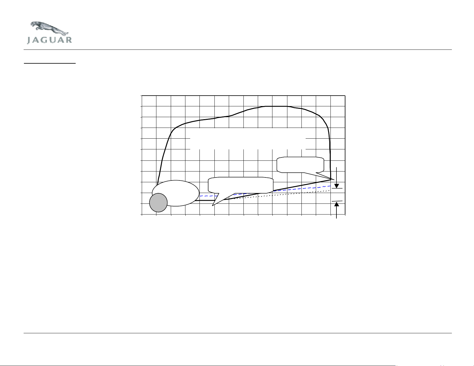
The misfire monitor operates continuously within the boundaries of the regulated monitor operation window, as shown below:
110
100
90
80
70
60
50
40
Relative Engine Load (%
30
20
10
0
0 500 1000 1500 2000 2500 3000 3500 4000 4500 5000 5500 6000 6500 7000
FTP75
Operating
Idle
Misfire Monitor Operating Region
(w ithin solid boundary)
Effect of 4"Hg
'P ressure R elief'
Stabilised engine, sea-level
minimum load line
Engine Speed (rpm)
Region of misfire monitor operation
After engine start, the monitor will enable as soon as the engine speed rises above the minimum operation speed (150 RPM below fully warm stabilized idle
speed). Two revolutions of crank angle data, i.e. One sample of data from each cylinder firing, are 'buffered' before any decisions can be made by the monitor.
Before engine speed has reached the top of the start flare the monitor will be ready to make misfire judgments, which are then made on every cylinder firing,
irrespective of whether the monitor is enabled or not.
Note: Unless specifically included in the tables below, IAT, ECT, vehicle speed and time after start up are not critical to enable these monitors.
Jaguar Cars Revision Date: May 2004 Page 19 of 113
Page 20
A
Misfire Monitor Operation – Up to 2004 Model Year
Strategy DTCs Description Malfunction Criteria Value Secondary Parameter Enable
Conditions
Random misfire P0300 Crank speed fluctuation Catalyst damage
Excessive emissions
Misfire cylinder
1
Misfire cylinder
2
Misfire cylinder 3 P0303 IAT
Misfire cylinder 4 P0304 Fuel level
Misfire cylinder 5 P0305 MIS2 1+2 DTC
Misfire cylinder 6 P0306 1+2 DTC
Misfire cylinder
7 (V8)
Misfire cylinder
8 (V8)
Misfire catalyst
damage 1
Misfire catalyst
damage 2
Misfire excess
emissions
Disable: P0101-P0103, P1104, P0111- P0113, P0116- P0118, P0125, P0107,
P0301
P0302
P0307 1+2 DTC
P0308 1+2 DTC
P1313 Catalyst damage % See table MIS1 No
P1314 Catalyst damage % No
P1316 Emissions failure
4.2L S/C Auto
Normally aspirated
Supercharged
Steady state
Engine speed (RPM)
4.2L N/A Auto
3.0L Manual
3.0L Auto
ECT
tmospheric pressure
Load
1.3%
1.3%
No
P0108, P0336, P0460, P0603, P0121- P0123, P0137, P0138, P0140,
P0157, P0158, P0160, P0171, P0172, P0174, P0175, P0181- P0183,
P1233, P1339, P0106, P0831, P0832, P1234, P1236, P1338, P0222,
P0223, P1224, P1229, P1230, P1251, P1516, P1609, P1611, P1631,
P1633, P1637, P1642. P0128, P0106, C1137, C1165, C1175
450 - 6500
450 – 6200
580 - 7000
530 - 7000
-8 to 120°C
-8 to 100°C
> 68 kPa
> 11%
> Value in map
Time
Required
200 or 1000
revolutions
1+2 DTC
1+2 DTC
1+2 DTC
MIL
1+2 DTC
1+2 DTC
Jaguar Cars Revision Date: May 2004 Page 20 of 113
Page 21

A
Misfire Monitor Operation – From 2004 Model Year
Strategy DTCs Description Malfunction Criteria Value Secondary Parameter Enable
Conditions
Random misfire
Misfire
cylinder 1
Misfire
cylinder 2
Misfire
cylinder 3
Misfire
cylinder 4
Misfire
cylinder 5
Misfire
cylinder 6
Misfire
cylinder 7 (V8)
Misfire
cylinder 8 (V8)
Misfire catalyst
damage 1
Misfire catalyst
damage 2
Misfire excess
emissions
Disable: C1137, C1145, C1155, C1165, C1175, P0101-P0103, P0106-P0108, P0111-P0113,
X-Type 2005 model year Disable additional: P0069, P0607, P0627-P0629, P0851, P2118, P2119, P2135, P2228, P2229, P2632-
P0300
P0301
P0302
P0303
P0304
P0305
P0306
P0307
P0308
P1313 Catalyst damage % See table MIS1 200 revolutions No
P1314 Catalyst damage % No
P1316 Emissions failure
Crank speed fluctuation Catalyst damage
Excessive emissions
4.2L S/C Auto (XK8)
IAT
Fuel level
MIS2
4.2L normally aspirated
4.2L supercharged
3.0L S-Type
X-Type manual
X-Type automatic
Steady state
Engine speed (RPM)
4.2L NA Auto (XK8)
4.2L NA Auto (XJ)
4.2L S/C Auto (XK8)
3.0L
ECT
tmospheric pressure
Load
1.3%
1.3%
1.3%
4.0%
2.0%
P0116-P0118, P0121-P0123, P0125, P0128, P0137, P0138, P0140, P0157, P0158,
P0160, P0171, P0172, P0174, P0175, P0181-P0183, P0191-P0193, P0222, P0223,
P0335, P0336, P0460, P0603, P0831, P0832. P1104, P1224, P1229, P1233, P1234,
P1236, P1251, P1338, P1339, P1516, P1609, P1611, P1631, P1633, P1637, P1642.
P2636
1000
450 to 6500
450 to 6200
450 to 6600
450 to 6400
530 - 7000
-8 to 119°C
-40 to 119 °C
> 68 kPa
> 75.5 kPa (XType)
> 11%
> Value in map
Time
Required
200 or 1000
revolutions
1+2 DTC
revolutions
1+2 DTC
1+2 DTC
1+2 DTC
1+2 DTC
1+2 DTC
1+2 DTC
1+2 DTC
1+2 DTC
No
MIL
Jaguar Cars Revision Date: May 2004 Page 21 of 113
Page 22
6.2.1 Misfire Detection
For the purposes of misfire detection, “steady - state“ is defined as:
• At least 1 second since fuel cut-off was last invoked.
• At least 1 second since gear change was last made.
• At least 0.5 seconds since rough road detected (1second for 3.0L).
• At least 1 second since acceleration ignition retard was last invoked.
• At least 1 second since >15% shunt control ignition retard was last invoked (3.0L only).
• At least 1 second since fuel cut-off ignition retard was last invoked.
• At least 1 second since ISC feedback status (off to on only) changed.
• At least 1 second since A/C status (on or off) changed.
• At least 1 second since electrical load status (on or off) changed.
• At least 1 second since traction control ignition retard was last invoked.
• Rate of change of engine speed less than 250 RPM/0.064s.
• Rate of change of engine load has been less than 0.1g/revolution for at least 20 firing cycles.
• Rate of change of throttle angle is less than 1.5 degrees/0.008s.
MIS1 – 2.5L
Engine speed (RPM) Engine
load (g/s)
0.30 148 148 138 116 100 100 100 90 82 74 42 32 32 20 18
0.60 124 124 108 108 90 82 70 64 58 50 42 32 32 20 18
0.80 106 106 106 100 82 74 60 56 50 42 36 30 24 20 18
1.00 100 100 100 82 74 66 50 50 42 32 30 28 32 20 20
1.20 88 88 88 74 62 44 42 40 32 32 28 28 32 30 30
1.40 88 88 88 74 62 60 56 56 48 36 36 32 32 36 36
1.60 88 88 88 74 62 60 56 56 48 36 36 32 32 36 36
2.00 88 88 88 74 62 60 56 56 48 36 36 32 32 36 36
Note: The figures in the map denote the number of misfires in 200 engine revolutions corresponding to catalyst damage misfire failure.
700 730 1000 1500 2000 2500 3000 3500 4000 4500 5000 5500 6000 6500 7000
Jaguar Cars Revision Date: May 2004 Page 22 of 113
Page 23

MIS1 – 3.0L (S-Type)
Engine speed (RPM) Engine
load (g/s)
680 730 1000 1500 2000 2500 3000 3500 4000 4500 5000 5500 6000 6500 7000
0.25 150 150 135 130 125 116 106 99 99 80 76 72 72 68 64
0.3 138 138 125 120 119 110 100 93 93 74 70 66 66 62 58
0.4 126 126 120 110 109 100 90 83 83 64 60 56 56 52 48
0.6 121 121 118 118 102 93 80 69 67 56 55 46 46 43 42
0.9 117 117 111 100 84 72 60 53 52 48 39 31 31 27 26
1.2 93 93 93 76 67 58 56 50 51 38 32 23 23 23 23
1.3 84 84 84 77 64 61 50 41 44 27 27 26 26 25 25
1.6 100 100 100 77 73 68 50 46 57 50 41 36 38 39 38
Note: The figures in the map denote the number of misfires in 200 engine revolutions corresponding to catalyst damage misfire failure.
MIS1 – 3.0L (X-Type)
Engine speed (RPM) Engine
load (g/s)
0.30 148 148 134 116 106 90 70 68 64 56 40 20 26 26 24
0.60 126 126 120 106 90 76 64 58 50 38 32 20 20 20 24
0.80 100 100 100 90 76 64 56 50 40 26 20 18 18 18 24
1.00 84 84 84 80 62 56 42 38 40 26 20 14 14 18 20
1.20 68 68 68 64 50 46 40 34 26 26 30 26 26 26 26
1.40 78 78 78 64 56 46 26 20 26 30 30 30 28 26 34
1.60 78 78 78 64 56 46 50 50 34 30 34 32 34 32 34
2.00 78 78 78 64 56 46 50 50 34 30 34 32 34 32 34
Note: The figures in the map denote the number of misfires in 200 engine revolutions corresponding to catalyst damage misfire failure.
700 730 1000 1500 2000 2500 3000 3500 4000 4500 5000 5500 6000 6500 7000
Jaguar Cars Revision Date: May 2004 Page 23 of 113
Page 24
MIS1 – 4.2L Normally Aspirated
Engine speed (RPM) Engine
load (g/s)
600 650 1000 1500 2000 2500 3000 3500 4000 4500 5000 5500 6000 6500
0.3 187 187 179 167 140 122 118 104 94 89 74 60 51 62
0.4 183 183 175 163 137 119 114 100 94 86 70 56 47 58
0.6 173 173 165 153 134 109 109 109 92 83 68 53 44 56
0.8 164 164 156 146 133 120 106 94 83 66 53 41 30 40
1.2 151 151 143 114 96 75 75 63 50 33 20 20 20 20
1.6 122 122 114 94 75 58 50 29 26 20 20 20 20 20
2.2 120 120 112 92 74 58 45 33 26 27 26 31 31 34
2.8 120 120 112 92 74 60 48 36 31 30 26 31 31 34
Note: The figures in the map denote the number of misfires in 200 engine revolutions corresponding to catalyst damage misfire failure.
MIS1 – 4.2L Supercharged
Engine speed (RPM) Engine
load (g/s)
600 650 1000 1500 2000 2500 3000 3500 4000 4500 5000 5500 6000 6200
0.4 186 186 180 164 150 134 117 101 89 77 64 68 72 74
0.6 186 186 178 160 150 130 110 97 85 73 60 64 68 70
1 183 183 175 159 142 125 108 93 77 63 49 51 52 53
1.6 158 158 150 134 117 104 90 72 54 50 46 52 57 60
2.2 125 125 117 109 100 93 85 66 47 49 52 58 64 68
2.8 122 122 114 88 62 52 42 50 57 56 56 68 80 84
3.4 116 116 108 84 60 55 50 54 58 57 57 69 74 77
3.8 116 116 108 84 60 55 50 53 61 65 70 71 73 77
Note: The figures in the map denote the number of misfires in 200 engine revolutions corresponding to catalyst damage misfire failure.
MIS2 – 2.5L Automatic
Engine speed (RPM) EOT (°C)
700 730 1000 1500 2000 2500 3000 7000
-10 0.64 0.64 0.64 0.43 0.43 0.43 0.43 0.72
20 0.39 0.39 0.39 0.33 0.33 0.33 0.34 0.63
50 0.27 0.27 0.27 0.25 0.26 0.26 0.27 0.56
80 0.22 0.22 0.22 0.20 0.22 0.22 0.23 0.52
Jaguar Cars Revision Date: May 2004 Page 24 of 113
Page 25
MIS2 – 2.5L Automatic (2005 Model Year X-Type)
Engine speed (RPM) EOT (°C)
500 650 1000 1150 1380 1800 2300 2550 2760 3000 7000
-8 0.45 0.45 0.45 0.45 0.45 0.46 0.47 0.47 0.47 0.47 0.72
15 0.32 0.32 0.32 0.32 0.33 0.37 0.38 0.38 0.38 0.38 0.63
45 0.26 0.26 0.26 0.26 0.28 0.32 0.32 0.32 0.32 0.32 0.57
80 0.21 0.21 0.23 0.24 0.25 0.26 0.27 0.28 0.28 0.28 0.53
MIS2 – 2.5L Manual
Engine speed (RPM) EOT (°C)
700 730 1000 1500 2000 2500 3000 7000
-10 0.47 0.47 0.47 0.33 0.33 0.34 0.35 0.64
20 0.32 0.32 0.32 0.26 0.26 0.27 0.28 0.57
50 0.23 0.23 0.23 0.21 0.22 0.23 0.24 0.53
80 0.19 0.19 0.19 0.18 0.19 0.20 0.20 0.49
MIS2 – 2.5L Manual (2005 Model Year X-Type)
Engine speed (RPM) EOT (°C)
500 650 785 960 1165 1410 1725 2180 2700 3000 7000
-8 0.50 0.50 0.50 0.43 0.37 0.33 0.33 0.33 0.37 0.37 0.66
15 0.36 0.36 0.36 0.31 0.27 0.25 0.27 0.28 0.30 0.30 0.59
45 0.26 0.26 0.26 0.24 0.21 0.22 0.24 0.25 0.25 0.26 0.55
80 0.20 0.20 0.20 0.20 0.18 0.18 0.20 0.20 0.20 0.21 0.50
MIS2 – 3.0L S-Type Automatic
Engine speed (RPM) EOT (°C)
680 730 1000 1500 2000 2500 3000 7000
-8.1 0.599 0.599 0.599 0.523 0.504 0.504 0.504 0.832
20 0.404 0.404 0.404 0.409 0.399 0.4 0.38 0.709
50 0.34 0.33 0.32 0.32 0.32 0.32 0.35 0.678
80 0.295 0.29 0.27 0.27 0.255 0.26 0.26 0.589
Jaguar Cars Revision Date: May 2004 Page 25 of 113
Page 26

MIS2 – 3.0L S-Type Manual
Engine speed (RPM) EOT (°C)
680 730 1000 1500 2000 2500 3000 7000
-8.1 0.399 0.399 0.399 0.399 0.409 0.432 0.432 0.841
20 0.32 0.32 0.33 0.335 0.335 0.34 0.361 0.77
50 0.3 0.3 0.314 0.29 0.29 0.3 0.3 0.709
80 0.275 0.275 0.27 0.25 0.245 0.25 0.25 0.659
MIS2 – 3.0L X-Type Automatic
Engine speed (RPM) EOT (°C)
700 730 1000 1500 2000 2500 3000 7000
-10 0.55 0.55 0.55 0.44 0.44 0.44 0.44 0.79
20 0.41 0.41 0.41 0.35 0.36 0.36 0.36 0.71
50 0.32 0.32 0.32 0.28 0.29 0.29 0.30 0.65
80 0.24 0.24 0.24 0.22 0.22 0.23 0.24 0.59
MIS2 – 3.0L X-Type Manual
Engine speed (RPM) EOT (°C)
700 730 1000 1500 2000 2500 3000 7000
-10 0.54 0.54 0.54 0.37 0.37 0.38 0.38 0.72
20 0.36 0.36 0.36 0.30 0.30 0.30 0.30 0.64
50 0.25 0.25 0.25 0.24 0.24 0.25 0.25 0.59
80 0.23 0.23 0.23 0.20 0.20 0.20 0.21 0.55
MIS2 – 4.2L Normally Aspirated
Engine speed (RPM) EOT (°C)
600 650 1000 1500 2000 2500 3000 6500
-8 0.45 0.45 0.45 0.45 0.46 0.46 0.46 0.88
20 0.38 0.38 0.38 0.39 0.4 0.4 0.42 0.83
50 0.31 0.31 0.31 0.32 0.33 0.33 0.34 0.75
80 0.24 0.24 0.24 0.25 0.26 0.25 0.26 0.67
Jaguar Cars Revision Date: May 2004 Page 26 of 113
Page 27
MIS2 – 4.2L Supercharged
Engine speed (RPM) EOT (°C)
600 650 1000 1500 2000 2500 3000 6500
-8 0.6 0.6 0.6 0.6 0.62 0.64 0.66 1.21
20 0.5 0.5 0.5 0.51 0.51 0.52 0.54 1.09
50 0.37 0.37 0.37 0.38 0.4 0.41 0.44 0.99
80 0.28 0.28 0.28 0.28 0.29 0.31 0.35 0.9
6.3 Heated Oxygen Sensor Monitor
An O2S comprises of a gas-tight zirconium dioxide ceramic tube covered with thin layer of platinum. One end of the tube is open to atmosphere; the other end is
sealed and protrudes into the exhaust. When the tube is filled with oxygen rich atmospheric air, and the outer walls are exposed to the oxygen depleted exhaust
gases, a chemical reaction takes place and produces a voltage. The voltage output reflects the differences in oxygen concentrations on either side of the ceramic
sensor element. As the oxygen content decreases, the voltage increases. As the oxygen content increases, the voltage decreases.
The oxygen content of the exhaust gas stream is directly related to the air fuel mixture supplied to the engine. The voltage output by the O2S is typically 800 to
1000mV for rich mixtures, and around 100mV for lean mixtures.
The ceramic material in the sensor becomes sensitive to the presence of oxygen in the exhaust gas stream at around 315°C. An internal heater is used to bring
the sensor quickly up to the operating temperature.
The engine management system runs two tests on the upstream and downstream HO2S, one on the sensor operation and one on the sensor’s internal heater.
Note: Only the rear HO2S are used for fuel control.
6.3.1 Downstream Oxygen Sensors High/Low Input Monitor
The downstream O2S are checked for their maximum and minimum output values. The monitor increments an execution timer if the monitor entry conditions are
satisfied. A low voltage failure is judged if the output of the sensor does not exceed a calibrated value prior to the monitor execution timer exceeding its calibrated
failure threshold. A high voltage failure is judged if the sensor output remains above a calibrated value after the monitor execution timer has exceeded its
calibrated failure threshold or after a defined period of over run fuel cut off has been conducted. Additionally, a high voltage failure is invoked if the sensor
voltage exceeds battery short threshold for the required time.
Note: Unless specifically included in the tables below, IAT, ECT, vehicle speed and time after start up are not critical to enable these monitors.
Jaguar Cars Revision Date: May 2004 Page 27 of 113
Page 28

A
A
Heated Oxygen Sensor Monitor Operation – Up to 2004 Model Year
Strategy DTCs Description Malfunction Criteria Value Secondary Parameter Enable
Downstream
HO2S bank 1
high voltage
Downstream
HO2S bank 2
high voltage
P0138 Sensor voltage stuck high Sensor voltage
P0158 Disable: See HO2S
.9 volts
During fuel cut
off, duration >
3.8s
2 volts anytime
ir fuel rate feedback
compensation:
Closed loop compensation:
Closed loop compensation
verage:
ECT:
IAT:
Time after start up
0.75 – 1.25
0.5 – 1.5
0.85 – 1.15
70 – 110 °C
-8 – 100 °C
2 seconds
downstream no
activity check.
Heated Oxygen Sensor Monitor Operation – From 2004 Model Year (XK8, S-Type and New XJ)
Strategy DTCs Description Malfunction Criteria Value Secondary Parameter Enable
Conditions
Downstream
HO2S bank 1
high voltage
Downstream
HO2S bank 2
high voltage
P0138 Sensor voltage stuck high Sensor voltage
P0158 Immediate
Disable: See HO2S downstream no activity check.
= 0.95 volts
>=2 volts anytime
During fuel cut off, duration >= 3.8s (XK8)
>= 5s (S-Type)
>= 3.5s (XJ)
Conditions
Time
Required
60s 2 DTC
2 DTC
Time
Required
3.8s (XK8)
5s (S-Type)
3.5s (XJ)
0.5s (XJ)
MIL
MIL
2 DTC
2 DTC
Jaguar Cars Revision Date: May 2004 Page 28 of 113
Page 29

A
A
A
A
Heated Oxygen Sensor Monitor Operation – From 2004 Model Year (X -Type)
Strategy DTCs Description Malfunction Criteria Value Secondary Parameter Enable
Downstream
HO2S bank 1
low input
Downstream
HO2S bank 2
low input
Downstream
HO2S bank 1
high input
Downstream
HO2S bank 2
high voltage
P0137 Sensor voltage stuck low Sensor voltage
P0157
P0138 Sensor voltage stuck high Sensor voltage
or
P0158 Sensor voltage > 1.24 volts
Disable: See HO2S downstream no activity check.
0.30 volts Heater control
HO2S heater power
Engine speed
MAF
tmospheric pressure
Target Lambda
ECT
IAT
> 0.80 volts Time after start
Closed loop fuelling
Over run fuel cut off time
nytime 0.5s 2 DTC
ctive
>=180 Watt sec
>= 1500 RPM
>= 15 g/s
>= 74.5 kPa
0.75 to 1
70 to 119 °C
-10 to 119°C
>= 30s
ctive
>= 30s (high I/P)
Conditions
Time
Required
151s 2 DTC
2 DTC
151s 2 DTC
6.3.2 Downstream Oxygen Sensors Heater Circuit High
Heater resistance checks are performed when the heater is commanded on. If resistance values are outside of the limits when the heater is enabled, then a
failure judgment is made.
Note: Unless specifically included in the tables below, IAT, ECT, vehicle speed and time after start up are not critical to enable these monitors.
Heated Oxygen Sensor Monitor Operation
Strategy DTCs Description Malfunction Criteria Value Secondary Parameter Enable
Heater control
circuit bank 1
high input
Heater control
circuit bank 2
downstream
high input
P0038 Heater resistance check when
on
P0058 Heater resistance when on Outside limits
Outside limits 0.432s
Disable:
P1609, P0603
Conditions
Time
Required
0.4s (2004
model year)
0.432s
0.4s (2004
model year)
2 DTC
2 DTC
MIL
MIL
Jaguar Cars Revision Date: May 2004 Page 29 of 113
Page 30

6.3.3 Downstream Oxygen Sensors Heater Circuit Low
Heater resistance checks are performed when the heater is commanded off. If resistance values are outside of the limits, then a failure is flagged.
Note: Unless specifically included in the tables below, IAT, ECT, vehicle speed and time after start up are not critical to enable these monitors.
Heated Oxygen Sensor Monitor Operation
Strategy DTCs Description Malfunction Criteria Value Secondary Parameter Enable
Conditions
Heater control
circuit bank 1
low input
Heater control
circuit bank 2
low input
Disable: P1609, P0603
P0037 Heater resistance check when
off
P0057 Heater resistance check when
off
Outside limits 0.384s
Outside limits 0.384s
Time
Required
0.4s (2004
model year)
0.4s (2004
model year)
MIL
2 DTC
2 DTC
6.3.4 Downstream Oxygen Sensors No Activity Detected
The monitor is single shot monitor (runs once per trip), which is designed to operate only when the sensor has been lit off (up to operating temperature). The
monitor can be sub divided into two sections:
Stuck low
(Output voltage less than calibrated threshold (0.4 volts).
The monitor initially examines the fuelling control to ensure the system is stable, that linear airflow rate closed loop control, and sub feedback execution has been
invoked. Once these conditions are satisfied and a calibrated load/airflow has been achieved, a lean stuck timer is incremented. The monitor then checks the
output voltage from the sensor and sets a normal end judgment if a calibrated change in sensor output voltage is observed. If the change in sensor voltage is not
detected and the lean stuck timer exceeds the failure threshold, and the associated failure conditions are satisfied, then a failure end judgment is made.
Stuck high
(Output voltage greater than calibrated threshold (0.4 volts).
Again, the monitor strategy checks for stable air fuel ratio control prior to commencing the examination of the sensors output voltage. The monitor then utilizes
the lean switching characteristics of the sensor during an over run fuel cut off (where the sensors output voltage tends towards 0 volts), to determine its correct
Jaguar Cars Revision Date: May 2004 Page 30 of 113
Page 31

A
A
operation. Finally, if the duration of the fuel cut off exceeds a calibrated period and the output voltage of the sensor is greater than calibrated threshold, then a
failure judgment is set.
Note: Unless specifically included in the tables below, IAT, ECT, vehicle speed and time after start up are not critical to enable these monitors.
Heated Oxygen Sensor Monitor Operation – Up to 2004 Model Year
Strategy DTCs Description Malfunction Criteria Value Secondary Parameter Enable
Conditions
HO2S bank 1
no activity
HO2S bank 2
no activity
Disable: P1313, P1314, P1316, P0106 – P0108,
Bank 1 P0131 – P0133, P0171, P0172, P0351,
Bank 2 P0151 – P0153, P0174, P0175, P0352,
P0140
P0160
HO2S voltage Sensor voltage < 0.4 volts for
600s
> 0.4 volts during
fuel cut off
Heater energy
irflow
Engine speed
ECT
IAT
Short term fuel trim
Total fuel trim
Sub feedback control
Linear air fuel control
tmospheric pressure
Fuel level
> 524 Joules
> 10 g/s
> 1500 RPM
> 40 °C
-10 °C
0.75 – 1.25
0.5 – 1.5
Executing
Executing
>= 70 kPa
>= 0 kPa (2004
model year V6 SType)
> 11%
P0116 – P0118, P0125, P1367, P1368,
P0444, P0445, P0111 – P0113, P1234,
P1236, P1338, P0101 – P0103, P1104,
P1637, P1642, P0603, P0460, P1609, P0128,
P1229, P1224, P0121 – P0123, P1251,
P1631, P1611, P1633, P0441, P0443, P0222,
P0223, P0191- P0193, P0181- P0183 C1165,
C1175, C1137
P0353, P0355, P0357, P0201, P0203, P0205,
P0207 P0031, P0032, P0037, P0038
P0354, P0356, P0358 P0202, P0204, P0206,
P0208 P0051, P0052, P0057, P0058.
Required
600s
3.8s
Time
MIL
2 DTC
2 DTC
Jaguar Cars Revision Date: May 2004 Page 31 of 113
Page 32

A
A
Heated Oxygen Sensor Monitor Operation – From 2004 Model Year (XK8, S-Type and new XJ)
Strategy DTCs Description Malfunction Criteria Value Secondary Parameter Enable
Conditions
HO2S bank 1
no activity
HO2S bank 2
no activity
Sensor voltage stuck during
Sensor voltage stuck during
Disable: C1137, C1145, C1155, C1165, C1175, P0101, P0102, P0103, P0106,
Bank 1 P0031, P0032, P0037, P0038, P0131, P0132, P0133, P0171, P0172,
Bank 2 P0051, P0052, P0057, P0058, P0151, P0152, P0153, P0174, P0175,
P0140
P0160
HO2S voltage Sensor voltage Heater energy
irflow
Engine speed
ECT
IAT
tmospheric pressure
Fuel level
normal closed loop control
or
over run fuel cut off
<= 0.4 volts with
movement of
< 0.2 volts
> 0.4 volts with
movement of
< 0.2 volts
Short term fuel trim
Total fuel trim
Sub feedback control
Over run fuel cut off
duration
P0107, P0108, P0111, P0112, P0113, P0116, P0117, P0118, P0121,
P0122, P0123, P0125, P0128, P0181, P0182, P0183, P0191, P0192,
P0193, P0222, P0223, P0441, P0443, P0444, P0445, P0460, P0603,
P1104, P1224, P1229, P1233, P1234, P1236, P1251, P1313, P1314,
P1316, P1338, P1339, P1367, P1368, P1609, P1611, P1631, P1633,
P1637, P1642
P0201, P0203, P0205, P0207, P0351, P0353, P0355, P0357
P0202, P0204< P0206, P0208, P0352, P0354, P0356, P0358
>= 524 Joules
>= 10 g/s
>= 1500 RPM
>= 40 °C
>= -10 °C
>= 70 kPa
> 11%
0.75 – 1.25
0.5 – 1.5
Executing
>= 3.8s (XK8)
>= 3.5s (XJ)
>= 5s (S-Type)
Time Required MIL
600s
3.8s (XK8)
3.5s (XJ)
5s (S-Type)
2 DTC
2 DTC
Jaguar Cars Revision Date: May 2004 Page 32 of 113
Page 33

A
A
A
A
Heated Oxygen Sensor Monitor Operation – From 2004 Model Year (X-Type)
Strategy DTCs Description Malfunction Criteria Value Secondary Parameter Enable
Conditions
HO2S bank 1
no activity
HO2S bank 2
no activity
Disable: C1137, C1145, C1155, C1165, C1175, P0101, P0102, P0103, P0106,
Disable Additions (2005 model year): P0069, P0335, P0336, P0607,P0627, P0628, P0629, P2118, P2119,
Bank 1 P0031, P0032, P0037, P0038, P0131, P0132, P0133, P0171, P0172,
Bank 2 P0051, P0052, P0057, P0058, P0151, P0152, P0153, P0174, P0175,
P0140
P0160
HO2S voltage Sensor voltage < 0.5 v Heater control
Heater energy
MAF
Engine speed
ECT
IAT
tmospheric pressure
fter start time
Target Lambda
Closed loop fuelling
Over run fuel cut off
duration
P0107, P0108, P0111, P0112, P0113, P0116, P0117, P0118, P0121,
P0122, P0123, P0125, P0128, P0181, P0182, P0183, P0191, P0192,
P0193, P0222, P0223, P0441, P0443, P0444, P0445, P0460, P0603,
P1104, P1224, P1229, P1233, P1234, P1236, P1251, P1313, P1314,
P1316, P1338, P1339, P1367, P1368, P1609, P1611, P1631, P1633,
P1637, P1642
P2135, P2228, P2229, P2632, P2633, P2634, P2635, P2636
P0201, P0203, P0205, P0207, P0351, P0353, P0355, P0357
P0202, P0204< P0206, P0208, P0352, P0354, P0356, P0358
ctive
>= 180 watts sec
>=15 g/s
>= 1500 RPM
70 to 119 °C
-10 to 119 °C
>= 74.5 kPa
30s
0.75 to 1
ctive
>= 3.0s
Required
151s
Time
MIL
2 DTC
2 DTC
Jaguar Cars Revision Date: May 2004 Page 33 of 113
Page 34

A
A
A
A
6.3.5 Upstream Oxygen Sensors Circuit
This monitors the upstream O2S element current. If the current is above or below a calibrated value, and the stable operating conditions are satisfied, a failure
timer is incremented, otherwise a normal timer is incremented. Upon exceeding the calibrated thresholds for either the failure/normal timers, an appropriate
failure/normal end judgment is set.
Note: Unless specifically included in the tables below, IAT, ECT, vehicle speed and time after start up are not critical to enable these monitors.
Heated Oxygen Sensor Monitor Operation
Strategy DTCs Description Malfunction Criteria Value Secondary Parameter Enable Conditions Time
HO2S bank 1
low input
HO2S bank 2
low input
HO2S bank 1
high input
HO2S bank 2
high input
Disable:
Disable:
P0131 Element current Element current stuck low <= - 15.0 mA Closed loop fuelling
Sub feedback control
HO2S voltage
Engine speed
P0151
P0132 Element current Element current stuck high >= 15.0 mA
P0152 Purge vapor
fter start time
Vehicle speed
ECT
IAT
tmospheric pressure
MAF
Delta load
Element impedance
concentration or
Purge
Fuel cut off
Bank 1
Bank 2
Bank 1
Bank 2
ctive
ctive
0.2 – 0.85 volts
>= 1500 RPM
>= 0.9s
>= 9 mph
>= 40 °C
>= - 40 °C
>= 75 kPa
>= 10 g/s
< 3.125 g/revolutions/s
for >2s
(=< 0.05 g/revolutions/s
for 3.0L)
20 – 60 ohms
0 – 60 ohm (X-Type)
>= 0.9
Not active
Not active
P0132
P0152
P0131
P0151
10s 2 DTC
10s 2 DTC
2 DTC
2 DTC
Required
MIL
Jaguar Cars Revision Date: May 2004 Page 34 of 113
Page 35

A
A
A
6.3.6 Upstream Oxygen Sensors Slow Response
The failure criteria for this monitor is the measurement of the time taken for the upstream sensor to attain a calibrated air fuel ratio reading following fuel reinstatement after an over run fuel cut off. The slow response monitor measures the response time of the sensor to react when the air fuel ratio changes from a
known lean state to a known non-lean state. The monitor operates after fuelling has been reinstated and the engine management system is in ISC mode,
following a period of fuel cut off. If all execution conditions are satisfied the monitor increments a response timer, if the timer exceeds a failure threshold prior to
the sensor current switching back to a non-lean condition (6.97mA) a failure end judgment flag is set. If the current signal passes through the lean limit prior to
the timer exceeding the failure threshold, then a normal end judgment is set. It should be noted that the slow response monitor is a single shot monitor, which
only executes once per drive cycle.
Fuel Cut Off Operation
A timer is employed to ensure that a minimum period of fuel cut off is achieved prior to executing the monitor. This allows the sensors to respond to the lean air
fuel ratio fuelling shift, which occurs during the period of fuel cut off.
Note: Unless specifically included in the tables below, IAT, ECT, vehicle speed and time after start up are not critical to enable these monitors.
Strategy DTCs Description Malfunction Criteria Value Secondary Parameter Enable
HO2S bank 1
slow response
HO2S bank 2
slow response
Disable: P1316, P0106–P0108, P0116–P0118, P0125, P0128, P1367, P1368,
Bank 1
P0133 Response time of sensor from
P0153 Element impedance
lean to rich after over run fuel
cut off
Heated Oxygen Sensor Monitor Operation – Up to 2004 Model Year
Response rate time 2.6s (4.2L NA)
> 4.02s (S-Type)
> 3.2s (S/C)
Bank 2
Engine speed
irflow
ECT
IAT
tmospheric pressure
Throttle closed flag
Fuel cut off time
Closed loop fuelling
P0111–P0113, P1313, P1314, P0444, P0445, P1234, P1236, P1338,
P0101– P0103, P1104, P1637, P1642, P0603, P0460, P1609, P1229,
P1224, P0121-P0123, P0222, P0223, P1251, P1631, P1611, P1633,
P0441, P0443, P0181-P0183, P0191-P0193, C1165, C1175, C1137
P0132, P0131, P0137, P0138, P0140, P0172, P0171, P0351, P0353,
P0355, P0357, P0201, P0203, P0205, P0207, P0031, P0032.
P0152, P0151, P0157, P0158, P0160, P0174, P0175, P0352, P0354,
P0356, P0358, P0202, P0204, P0206, P0208, P0051, P0052.
Conditions
600 – 4000 RPM
< 70 g/s
70 to 110 °C
-30 to 100 °C
> 68 kPa
20 to 60 ohm
Set
2 – 40s
ctive
Time
Required
< 5s 2 DTC
2 DTC
MIL
Jaguar Cars Revision Date: May 2004 Page 35 of 113
Page 36

A
A
A
Heated Oxygen Sensor Monitor Operation – From 2004 Model Year
Strategy DTCs Description Malfunction Criteria Value Secondary Parameter Enable
Conditions
HO2S bank 1
slow response
HO2S bank 2
slow response
Disable: C1137, C1145, C1155, C1165, C1175, P0101, P0102, P0103, P0106,
Disable additions (2005 model year X-Type): P0069, P0335, P0336, P0607,P0627, P0628, P0629, P2118, P2119,
Bank 1
P0133 Response time of sensor from
lean to rich after over run fuel
cut off
P0153 Throttle closed flag
Response rate time >= 3.5s (X-Type)
>= 4.0s (S-Type)
>= 2.6s (XJ N/A)
>= 3.2s (XJ S/C)
>= 2.6s (XK8 N/A)
>= 4.0s (XK8 S/C)
Bank 2
Engine speed
irflow
ECT
IAT
tmospheric pressure
Element impedance
Fuel cut off time
Closed loop fuelling
P0107, P0108, P0111, P0112, P0113, P0116, P0117, P0118, P0121,
P0122, P0123, P0125, P0128, P0181, P0182, P0183, P0191, P0192,
P0193, P0222, P0223, P0441, P0443, P0444, P0445, P0460, P0603,
P1104, P1224, P1229, P1233, P1234, P1236, P1251, P1313, P1314,
P1316, P1338, P1339, P1367, P1368, P1609, P1611, P1631, P1633,
P1637, P1642
P2135, P2228, P2229, P2632, P2633, P2634, P2635, P2636
P0132, P0131, P0137, P0138, P0140, P0172, P0171, P0351, P0353,
P0355, P0357, P0201, P0203, P0205, P0207, P0031, P0032.
P0152, P0151, P0157, P0158, P0160, P0174, P0175, P0352, P0354,
P0356, P0358, P0202, P0204, P0206, P0208, P0051, P0052.
600 – 4000 RPM
< 70 g/s
70 to 110 °C
-30 to 100 °C
> 68 kPa
0 to 60 ohm
20 to 60 ohm
(XK8)
0 to 60 ohm (XType)
Set
2 to 60s (X-Type)
4 to 60s (S-Type)
2 to 40s (XJ)
ctive
Time Required MIL
3.5s (X-Type)
4.0s (S-Type)
2.6s (XJ N/A)
3.2s (XJ S/C)
2.6s (XK8 N/A)
4.0s (XK8 S/C)
2 DTC
2 DTC
6.3.7 Upstream Oxygen Sensors Heater Circuit
The control module monitors the heater current to be within limits. If a failure is detected, the control module responds by setting the appropriate signal failure
code. On detection of a failure code the monitor proceeds to increment a failure timer and a judgment is made if the failure timer exceeds a calibrated threshold.
If a failure code is not present, then the monitor increments a normal judgment timer and sets a judgment upon exceeding a calibrated threshold.
Note: Unless specifically included in the tables below, IAT, ECT, vehicle speed and time after start up are not critical to enable these monitors.
Jaguar Cars Revision Date: May 2004 Page 36 of 113
Page 37

A
Heated Oxygen Sensor Monitor Operation
Strategy DTCs Description Malfunction Criteria Value Secondary Parameter Enable
Heater control
circuit bank 1
low input
Heater control
circuit bank 1
high input
Heater control
circuit bank 2
low input
Heater control
circuit bank 2
high input
P0031 Control module monitors heater
for current to be within limits
P0032 Control module monitors heater
for current to be within limits
P0051 Control module monitors heater
for current to be within limits
P0052 Control module monitors heater
for current to be within limits
Outside limits HO2S control Executing 3.6s 2 DTC
Outside limits HO2S control Executing 3.6s 2 DTC
Outside limits HO2S control Executing 3.6s 2 DTC
Outside limits HO2S control
Disable:
Executing
P1609, P0603
Conditions
Time
Required
3.6s 2 DTC
MIL
6.3.8 Control Module
The control function within the ECM enables hardware checks to be performed on the sensors. These DTCs will reflect sensor open circuit and short circuit faults
along with heater faults. In addition to sensor fault monitoring these DTCs will also reflect failures of the control functions themselves. The sensor impedance is
also monitored to ensure that its impedance is below the required level for correct operation after the sensor has been active for the required time.
Note: Unless specifically included in the tables below, IAT, ECT, vehicle speed and time after start up are not critical to enable these monitors.
Heated Oxygen Sensor Monitor Operation
Strategy DTCs Description Malfunction Criteria Value Secondary Parameter Enable
Control module
open/shorted bank
1
Control module
open/shorted bank
2
P1646 Control module hardware
checks
P1647 Sensor impedance > 60 ohms Sensor control active
Heater failure
Sensor open circuit
Sensor short circuit
Module failure
Failed
Failed
Failed
Failed
Sensor control Executing
Disable:
Ignition on
>= 60s
P0603
Conditions
Time
Required
8.0s
8.0s
8.0s
8.0s
ll 3.6s (2004
model year)
20s 2 DTC
MIL
2 DTC
Jaguar Cars Revision Date: May 2004 Page 37 of 113
Page 38

6.4 Fuel System Monitor
The monitor operates continuously throughout the trip. The monitor timing is every 0.128 seconds. The monitor compares the long term adaptions for the current
load site against a failure threshold. If the adaptions for that site are greater than the failure threshold, the long term failure counter is incremented. If this counter
reaches a calibrated time, the monitor looks at the short term fuelling trim and compares this against another threshold. The short term failure counter is
incremented and if this counter reaches its failure threshold then a failure is flagged.
The normal counter operates when both long term and short term fuelling is within the thresholds. If the normal counter reaches its calibrated time then both
failure counters are reset.
The diagram below shows the flagging of a rich failure on bank 1of an engine:
Note: Unless specifically included in the tables below, IAT, ECT, vehicle speed and time after start up are not critical to enable these monitors.
Jaguar Cars Revision Date: May 2004 Page 38 of 113
Page 39

A
Fuel System Monitor (V8) – Up to 2004 Model Year
Strategy DTCs Description Malfunction Criteria Value Secondary Parameter Enable
Conditions
Fuel too lean –
bank 1
Fuel too lean –
bank 2
Fuel too rich
– bank 1
Fuel too rich
– bank 2
Disable: P1313, P1314, P1316, P0106, P0107, P0108, P0116, P0117, P0118, P0125, P1367, P1368, P0444, P0445, P0111,
Bank 1 P0133, P0137, P0138, P0140, P0351, P0353, P0355, P0357 P0201, P0203, P0205, P0207, P0031, P0032, P0037,
Bank 2 P0153, P0157, P0158, P0160, P0352, P0354, P0356, P0358, P0202, P0204, P0206, P0208, P0051, P0052, P0057,
P0171
P0174
P0172
P0175
Long term fuelling drift and short
term feedback compensation
values outside limits
Long term adaptions
Long term adaptions
Total air fuel rate feedback
compensation
Total air fuel rate feedback
compensation
P0112, P0113, P1234, P1236, P1338, P0102, P0103, P1104, P0101, P1642, P0603, P0460, P1609, P0128, P0443,
P0441, P0191, P0192, P0193, P0181, P0182, P0183, P1233, P1339
P0038
P0058
> +18% and
> +19%
< -17% and
< -16%
ECT
IAT
Closed loop fuelling
Fuel level
> 75 °C
> -30 °C
ctive
> 11%
2 DTC
Time Required MIL
15s 2 DTC
2 DTC
2 DTC
Fuel System Monitor (V8) – From 2004 Model Year
Strategy DTCs Description Malfunction Criteria Value Secondary Parameter Enable
Conditions
Fuel too lean –
bank 1
Fuel too lean –
bank 2
Fuel too rich bank 1
Fuel too rich
- bank 2
Disable: P0101, P0102, P0103, P0106, P0107, P0108, P0111, P0112, P0113, P0116, P0117, P0118, P0125, P0128, P0181,
Bank 1 P0133, P0137, P0138, P0140, P0351, P0353, P0335, P0357 P0201, P0203, P0205, P0207, P0031, P0032, P0037,
Bank 2 P0153, P0157, P0158, P0160, P0352, P0354, P0356, P0358, P0202, P0204, P0206, P0208, P0051, P0052, P0057,
P0171
P0174
P0172
P0175
Long term fuel trim and short
term fuel trim values outside
limits
Long term fuel trim
Long term fuel trim
Short tem fuel trim
Short tem fuel trim
P0182, P0183, P0191, P0192, P0193, P0441, P0443, P0444, P0445, P0460, P0603, P1104, P1233, P1234, P1236,
P1313, P1314, P1316, P1338, P1339, P1367, P1368, P1609, P1642.
P0038
P0058
>= +18% (XK8)
>= +19% (XJ)
>= +19% (XK8)
>= +19% (XJ)
>= -17% (XK8)
>= -20% (XJ)
>= -16% (XK8)
>= -25%(XJ)
Fuel level
Transient fuelling
compensation
15s plus
>= 11%
<= 4 (+/-)
Time
Required
15s plus
15s
15s
MIL
2 DTC
2 DTC
2 DTC
2 DTC
Jaguar Cars Revision Date: May 2004 Page 39 of 113
Page 40

A
Fuel System Monitor (V6) – Up to 2004 Model Year
Strategy DTCs Description Malfunction Criteria Value Secondary Parameter Enable
Conditions
Fuel too lean –
bank 1
Fuel too lean –
bank 2
Fuel too rich –
bank 1
Fuel too rich –
bank 2
Disable: P1313, P1314, P1316, P0106, P0107, P0108, P0116, P0117, P0118, P0125, P1367, P1368, P0444, P0445, P0111,
Bank 1 P0133, P0137, P0138, P0140, P0351, P0353, P0335, P0357 P0201, P0203, P0205, P0207, P0031, P0032, P0037,
Bank 2 P0153, P0157, P0158, P0160, P0352, P0354, P0356, P0358, P0202, P0204, P0206, P0208, P0051, P0052, P0057,
P0171
P0174
P0172
P0175
Long term fuelling drift and short
term feedback compensation
values outside limits
Long term adaptions
Long term adaptions
Short term feedback
Short term feedback
P0112, P0113, P1234, P1236, P1338, P0102, P0103, P1104, P0101, P1642, P0603, P0460, P1609, P0128, P0443,
P0441, P0191, P0192, P0193, P0181, P0182, P0183, P1233, P1339
P0038
P0058
> 18%
> 25%
< 18%
< 25%
ECT
IAT
Closed loop fuelling
Fuel level
> 75 °C
> -30 °C
ctive
> 11%
2 DTC
Time Required MIL
60s 2 DTC
2 DTC
2 DTC
Fuel System Monitor (V6) – From 2004 Model Year
Strategy DTCs Description Malfunction Criteria Value Secondary Parameter Enable
Conditions
Fuel too lean –
bank 1
Fuel too lean –
bank 2
Fuel too rich
– bank 1
Fuel too rich
– bank 2
Disable: P0101, P0102, P0103, P0106, P0107, P0108, P0111, P0112, P0113, P0116, P0117, P0118, P0125, P0128, P0181,
Bank 1 P0133, P0137, P0138, P0140, P0351, P0353, P0355, P0357 P0201, P0203, P0205, P0207, P0031, P0032, P0037,
Bank 2 P0153, P0157, P0158, P0160, P0352, P0354, P0356, P0358, P0202, P0204, P0206, P0208, P0051, P0052, P0057,
P0171
P0174
P0172
P0175
Disable additions (X-Type 2005 model year):P0069, P0627, P0628, P0629, P2228, P2229, P2632, P2633, P2634, P2635, P2636.
Long term fuel trim and short
term fuel trim values outside
limits
Long term fuel trim
Long term fuel trim
Short tem fuel trim
Short tem fuel trim
P0182, P0183, P0191, P0192, P0193, P0441, P0443, P0444, P0445, P0460, P0603, P1104, P1233, P1234, P1236,
P1313, P1314, P1316, P1338, P1339, P1367, P1368, P1609, P1642.
P0038
P0058
>= +18% (S-Type)
>= +19% (X-Type)
>= +25%
>= -18%
>= -25%
Fuel level
Transient fuelling
compensation
30s plus
>= 11%
<= 4 (+/-)
Time
Required
30s plus
30s
30s
MIL
2 DTC
2 DTC
2 DTC
2 DTC
Jaguar Cars Revision Date: May 2004 Page 40 of 113
Page 41

6.4.1 Fuel System Secondary Trim
On the X-Type from 2004 model year, a secondary monitor also checks the sub feedback trim levels. When the entry conditions are met, the sub feed back trim
level is checked against a threshold. If it is either above or below a threshold, a counter is started, if at the end of the count the level is still above or below the
threshold then an appropriate DTC is flagged.
Note: Unless specifically included in the tables below, IAT, ECT, vehicle speed and time after start up are not critical to enable these monitors.
Fuel System Monitor - Secondary Fuel Trim (X-Type From 2004 Model Year)
Strategy DTCs Description Malfunction Criteria Value Secondary Parameter Enable
Conditions
Sub feedback too
lean bank 1
Sub feedback too
lean bank 2
Sub feedback too
rich bank 1
Sub feedback too
rich bank 2
Disable: P0101, P0102, P0103, P0106, P0107, P0108, P0111, P0112, P0113,
Disable (2005
Bank 1 P0133, P0137, P0138, P0140, P0351, P0353, P0335, P0357 P0201,
Bank 2 P0153, P0157, P0158, P0160, P0352, P0354, P0356, P0358, P0202,
P2096 Sub feedback outside limit Sub feedback trim value >= -3.49% MAF
ECT
Fuel level
P2098 Vapor concentration
Sub feedback
P2097 Sub feedback trim value >= 3.49%
P2097
P0116, P0117, P0118, P0125, P0128, P0181, P0182, P0183, P0191,
P0192, P0193, P0441, P0443, P0444, P0445, P0460, P0603, P1104,
P1233, P1234, P1236, P1313, P1314, P1316, P1338, P1339, P1367,
P1368, P1609, P1642.
P0069, P0101,P0102, P0103, P0116, P0117, P0118, P0125, P0191,
model year):
P0192, P0193, P0443, P0444, P0445, P0460, P0603, P0627, P0628,
P0629, P1104, P1367, P1368, P1638, P1642, P2228, P2229, P2632,
P2633, P2634, P2635, P2636.
P0203, P0205, P0207, P0031, P0032, P0037, P0038
P0204, P0206, P0208, P0051, P0052, P0057, P0058
>= 20 g/s
>= 60 °C
>= 10%
< 30 %
Executing
Time
Required
5s 2DTC
10 times 2DTC
MIL
Jaguar Cars Revision Date: May 2004 Page 41 of 113
Page 42

6.5 Evaporative Emissions System Monitor
The leak test monitor is designed to find any evaporative leak between 40 thou, (the EVAP reduces to 20 thou on V8 Sedan normally aspirated at 2001 model
year) and a gross leak. The 40 thou test operates whilst the vehicle is moving and includes checks for canister closure valve stuck closed (restricted airflow on
the fuel tank breather) and the EVAP canister purge valve stuck open (leaking). The EVAP canister closure valve stuck open and EVAP canister purge valve
stuck closed is part of the gross leak judgment. The 20 thou leak test is an additional test, which is carried out at idle.
DTCs
P0442 40 thou (or larger) leak detected
P0443 EVAP canister purge valve malfunction EVAP canister purge valve leaking
P0444 EVAP canister purge valve circuit low electrical circuit check
P0445 EVAP canister purge valve circuit high electrical circuit check
P0446 EVAP canister closure valve malfunction restricted airflow through tank breather
P0447 EVAP canister closure valve open circuit electrical circuit check
P0448 EVAP canister closure valve short circuit electrical circuit check
P0450 Fuel Tank Pressure (FTP) sensor malfunction no change in output
P0452 FTP sensor low input electrical circuit check
P0453 FTP sensor high input electrical circuit check
P0455 gross leak
P0456 20 thou leak
6.5.1 Leak Test Operation
The leak test will be initialized when a number of entry conditions are satisfied. They will include ECT, IAT, engine load, vehicle speed, vapor concentration and
purge amount.
40 Thou Leak Test
When the entry conditions are satisfied the EVAP canister purge valve will be closed and the EVAP canister closure valve will then close. The EVAP system is
now sealed, the FTP sensor will take the initial value of pressure (P1). After 15 seconds the FTP sensor will take a further reading (P2). The difference between
P1 and P2 becomes the first pressure rise.
The EVAP canister purge valve will then be ramped open to pull the FTP down to –2.00 kPa; the EVAP canister purge valve will then close. If the pressure rises
too quickly then a second pull down will occur. The FTP sensor then takes a further reading of the tank pressure (P3). After a further 15 seconds a final pressure
reading (P4) is taken. The difference between P3 and P4 becomes the second pressure rise.
Jaguar Cars Revision Date: May 2004 Page 42 of 113
Page 43

The EVAP canister closure valve is then opened and the leak value is calculated and compared with the pass/fail threshold. The result may be discarded if the
vapor concentration is too high, the first pressure rise is too high or the fuel movement in the tank causes excessive vapor. If the pressure in the tank does not
return close to atmospheric within a few seconds of the EVAP canister closure valve opening then the test will continue and may flag DTC P0446.
If the EVAP canister purge valve is ramped open and the tank is not pulled down to –2.00 kPa, a gross leak will be flagged. If however during the second
pressure rise the tank pressure rises to a value, which would indicate that it couldn't be a gross leak.
Failure to pull the tank pressure down resulting in flagging P0455 can be due to a gross leak, vapor pipe detached / fuel cap left off etc. or the EVAP canister
purge valve stuck closed or the EVAP canister closure valve stuck open.
Leak Test Diagram 40 Thou Test
closed
EVAP open
canister closure valve
EVAP canister
Purge Valve Duty
FTP 0.00kPa.
sensor
-2.00kPa
P2 P4P1
P3
Jaguar Cars Revision Date: May 2004 Page 43 of 113
Page 44

20 Thou Leak Test
The 20 thou leak test is similar to the diagram above, with the exception that the tank is pulled down to –1.25 kPa rather than –2.00 kPa as above. In addition
the 20 thou test is carried out at idle or with the vehicle moving at less then 9 mph. Component faults P0443, P0446, P0450 & P0455 cannot be determined from
the 20 thou test.
Jaguar Cars Revision Date: May 2004 Page 44 of 113
Page 45

A
A
Note: Unless specifically included in the tables below, IAT, ECT, vehicle speed and time after start up are not critical to enable these monitors.
Evaporative Emission System Monitor – Up to 2004 Model Year
Strategy DTCs Description Malfunction Criteria Value Secondary Parameter Enable
EVAP canister
purge valve low
voltage
EVAP canister
purge valve
high voltage
EVAP canister
purge valve
malfunction
EVAP canister
close valve
open
EVAP canister
close valve
shorted
EVAP canister
close valve
malfunction
FTP sensor
malfunction
Gross leak
detected
0.040" leak
detected
Conditions
P0444 Hardware check Commanded versus actual Wrong Battery voltage
EVAP canister purge valve
duty cycle
P0445 Hardware check Commanded versus actual Wrong Battery voltage
EVAP canister purge valve
duty cycle
P0443 Incorporated in to P0455/P0442 Pressure change -2 kPa
Disable:
P0447 Hardware check Commanded versus actual Wrong Ignition on 1.28s 2 DTC
P0448 Hardware check Commanded versus actual Wrong Leak check active
Disable:
P0446 Incorporated in to P0455/P0442 Pressure change/time < -0.4 kPa 150s
P0450 Incorporated in to P0455/P0442 Sensor activity < -0.03 kPa 120s
P0455 FTP during purge on, EVAP
canister closure valve open and
EVAP canister closure valve
closed conditions
P0442 FTP during purge on, EVAP
canister closure valve open and
EVAP canister closure valve
closed conditions
Pressure change over time Time/pressure Altitude change
Vehicle speed
Time after start
Pressure change over time See table
TBDF_LEAK_FA
LTLEVL_BASE
Fuel level
ltitude
IAT
Fuel level change
irflow
ECT
Purge accumulative
FTP
> 6 volts
< 0.102
> 6 volts
> 0.7
P0603, P1609,
P0441
P0603, P1609
> 625 ft
6.25 to 81mph
>765s
15 to 85%
< 10,000 ft
-8 to 100 °C
< 3%
2.5 to 40 g/s
70 to 110 °C
700
> -200 kPa
Required
3.2s 2 DTC
3.2s 2 DTC
120s
approximately
1.28s 2 DTC
approximately
approximately
94s
approximately
70s
approximately
Time
MIL
2 DTC
2 DTC
2 DTC
2 DTC
2 DTC
Jaguar Cars Revision Date: May 2004 Page 45 of 113
Page 46

A
A
A
A
Evaporative Emission System Monitor – Up to 2004 Model Year - Continued
Strategy DTCs Description Malfunction Criteria Value Secondary Parameter Enable
Conditions
0.020" leak
detected
Disable: P0101- P0103, P1104, P0107, P0108,
P0456 FTP during purge on, EVAP
canister closure valve open and
EVAP canister closure valve
closed conditions
Pressure change over time See table
TBDF_LEAK_FA
TLEVL_BASE20
Vehicle speed
Time after start
Fuel level
ltitude
IAT
Fuel level change
irflow
ECT
Purge amount after start
FTP
Engine run time
cumulative
Idle
irflow
Engine speed
Purge amount
< 9 mph
> 1400s
30-85%
< 10,000 ft
-8 to 70 °C
< 3%
1.5 to 15 g/s
70 to 110 °C
1100
> -1.25 kPa
9000s
lternative entry
conditions for
0.020" &0.040"
> 1400s
> 70g/s for > 3.5s
> 3500 RPM for >
3.5s
> 450
P0111- P0113, P0116- P0118, P0125,
P0128, P0201- P0208, P0351-P0358,
P0444, P0445, P0447, P0448, P0452,
P0453, P0460, P0603, P1609, P1642,
P1637, C1137, C1165, C1175, P1313,
P1314, P1316, P0106, P1637,
P1368, P1642, P0441
Time
Required
55s 2 DTC
MIL
Jaguar Cars Revision Date: May 2004 Page 46 of 113
Page 47

A
A
A
Evaporative Emission System Monitor – From 2004 Model Year
Strategy DTCs Description Malfunction Criteria Value Secondary Parameter Enable
EVAP canister
purge valve low
voltage
EVAP canister
purge valve
high voltage
EVAP canister
purge valve
malfunction
EVAP canister
close valve
open
EVAP canister
close valve
shorted
EVAP canister
close valve
malfunction
FTP sensor
malfunction
Gross leak
detected
0.040" leak
detected
P0444 Hardware check Commanded v actual Wrong Battery voltage
EVAP canister purge valve
duty cycle
P0445 Hardware check Commanded v actual Wrong Battery voltage
EVAP canister purge valve
duty cycle
P0443 Incorporated into P0455/P0442 Pressure change <= -1 kPa
Disable:
P0447 Hardware check Commanded v actual Wrong Ignition on 1.3s 2 DTC
P0448 Hardware check Commanded v actual Wrong Leak check active
Disable:
P0446 Incorporated into P0455/P0442 Pressure change/time <= -0. 2 kPa 150s
P0450 Incorporated into P0455/P0442 Sensor activity < -0.03 kPa 120s
P0455 FTP during purge on, EVAP
canister closure valve open and
EVAP canister closure valve
closed conditions
P0442 FTP during purge on, EVAP
canister closure valve open and
EVAP canister closure valve
closed conditions
Pressure change over time Time/pressure Atmospheric pressure
Vehicle speed
fter start
Pressure change over time See table EVAP1 Fuel level
tmospheric pressure
change
IAT
Fuel level change
irflow
ECT
Purge accumulative
FTP drop
< 10 volts
< 0.05
> 10 volts
> 0.9
P1609
P0603, P1609
>= 70 kPa (XK8
and S-type)
>= 74.5 kPa (XJ
and X-Type)
6 to 81mph
>=766s
15 to 85%
<= 2 kPa
-8 to 70°C
< 3%
2.5 to 40g/s
70 to 110°C
700
>= -2 kPa
Conditions
Time
Required
3.2s 2 DTC
3.2s 2 DTC
120s
approximately
1.3s 2 DTC
approximately
approximately
94s
approximately
70s
approximately
MIL
2 DTC
2 DTC
2 DTC
2 DTC
2 DTC
Jaguar Cars Revision Date: May 2004 Page 47 of 113
Page 48

A
A
A
A
A
Evaporative Emission System Monitor – From 2004 Model Year - Continued
Strategy DTCs Description Malfunction Criteria Value Secondary Parameter Enable Conditions Time
Required
0.020" leak
detected
Disable: C1137, C1145, C1155, C1165, C1175, P0031, P0032, P0051, P0052, P0101, P0102, P0103, P0106, P0107, P0108,
Disable additions (X-Type 2005
P0456 FTP during purge on, EVAP
canister closure valve open and
EVAP canister closure valve
closed conditions
model year)
Pressure change over time See table EVAP 2 Vehicle speed
fter start
Fuel level
tmospheric pressure
IAT
Fuel level change
irflow
ECT
Purge amount after start
FTP
Engine run time
calculation
lternative entry
conditions for 0.020"
and 0.040"
Idle
irflow
Engine speed
Purge amount
P0111, P0112, P0113, P0116, P0117, P0118, P0125, P0128, P0131, P0132, P0133, P0151, P0152, P0153, P0201,
P0202, P0203, P0204, P0205, P0206, P0207, P0208, P0351, P0352, P0353, P0354, P0355, P0356, P0357, P0358,
P0444, P0445, P0447, P0448, P0452, P0453, P0460, P0506, P0507, P0603, P1104, P1313, P1314, P1316, P1367,
P1368, P1609, P1637, P1638, P1642, P1646, P1647
P0069, P2228, P2229.
0 to 9 mph
>= 1400s
30 to 85%
>= 70 kPa (XK8 and Stype)
>= 74.5 kPa (XJ and XType)
-8 to 50 °C
-8 to 70 °C (Xk8)
<= 3%
1.5 to 15 g/s
70 to 110 °C
>= 1000 (X-Type)
>= 1100 (all other)
>= -1.25 kPa
>= 5000s (X-Type)
>= 9000s (S-Type)
>= 10000s (XK8)
>= 6000s (XJ N/A)
>= 5000s (XJ S/C)
> 1400s
> 70 g/s for > 3.5s
> 3500 RPM for > 3.5s
> 450
55s 2 DTC
MIL
Jaguar Cars Revision Date: May 2004 Page 48 of 113
Page 49

TBDF_LEAK_FALTLEVLBASE – 3.0L
Fuel level % 9 15 30 40 50 60 70 80 85 91
Threshold
level (kPa)
0.55 0.55 0.563 0.599 0.63 0.672 0.727 0.776 0.801 0.825
TBDF_LEAK_FALTLEVLBASE20 – 3.0L
Fuel level % 19 30 40 45 50 55 60 70 80 91
Threshold
level (kPa)
0.25 0.25 0.251 0.251 0.25 0.251 0.251 0.27 0.288 0.318
TBDF_LEAK_FALTLEVLBASE – 4.2L
Fuel level % 9 15 30 40 50 60 70 80 85 91
Threshold
level (kPa)
0.501 0.501 0.563 0.605 0.648 0.727 0.813 0.886 0.929 0.971
TBDF_LEAK_FALTLEVLBASE20 – 4.2L
Fuel level % 19 30 40 45 50 55 60 70 80 91
Threshold
level (kPa)
0.233 0.233 0.239 0.239 0.245 0.251 0.257 0.263 0.300 0.300
TBDF_LEAK_FALTLEVLBASE – 4.2L S/C
Fuel level % 9 15 30 40 50 60 70 80 85 91
Threshold
level (kPa)
0.630 0.630 0.630 0.630 0.660 0.697 0.752 0.819 0.949 0.898
TBDF_LEAK_FALTLEVLBASE20 – 4.2L S/C
Fuel level % 19 30 40 45 50 55 60 70 80 91
Threshold
level (kPa)
0.331 0.331 0.331 0.337 0.343 0.343 0.343 0.349 0.361 0.361
Jaguar Cars Revision Date: May 2004 Page 49 of 113
Page 50

EVAP1 – V6 (X-Type 2004 Model Year)
Fuel level % 19 30 40 45 50 55 60 70 80 91
Threshold level (kPa) 0.20 0.20 0.21 0.24 0.26 0.27 0.28 0.31 0.33 0.34
EVAP1 (X-Type 2005 Model Year)
Fuel level % 19 30 40 45 50 55 60 70 80 91
Threshold level (kPa) 0.19 0.19 0.19 0.19 0.19 0.19 0.19 0.21 0.24 0.28
EVAP1 – 3.0L (S-Type 2004 Model Year)
Fuel level % 19 30 40 45 50 55 60 70 80 91
Threshold level (kPa) 0.25 0.25 0.25 0.25 0.25 0.25 0.25 0.27 0.29 0.32
EVAP1 – 4.2L ( XJ 2004 Model Year)
Fuel level % 19 30 40 45 50 55 60 70 80 91
Threshold level (kPa) 0.25 0.25 0.27 0.28 0.29 0.29 0.30 0.33 0.39 0.45
EVAP1 – 4.2L ( XK8 2004 Model Year)
Fuel level % 19 30 40 45 50 55 60 70 80 91
Threshold level (kPa) 0.20 0.20 0.20 0.20 0.20 0.21 0.22 0.24 0.26 0.26
EVAP2 – V6 ( X-Type 2004 Model Year)
Fuel level % 9 15 30 40 50 60 70 80 85 91
Threshold level (kPa) 0.90 0.90 0.90 0.98 1.05 1.13 1.20 1.28 1.31 1.36
EVAP2 ( X-Type 2005 Model Year)
Fuel level % 9 15 30 40 50 60 70 80 85 91
Threshold level (kPa) 0.75 0.75 0.75 0.75 0.78 0.83 0.87 0.92 0.95 0.98
Jaguar Cars Revision Date: May 2004 Page 50 of 113
Page 51

EVAP2 – 3.0L (S-Type 2004 Model Year)
Fuel level % 9 15 30 40 50 60 70 80 85 91
Threshold level (kPa) 0.55 0.55 0.56 0.60 0.63 0.67 0.73 0.78 0.80 0.82
EVAP2 – 4.2L (XK8 2004 Model Year)
Fuel level % 10 20 30 40 50 55 60 70 80 91
Threshold level (kPa) 0.58 0.58 0.60 0.60 0.67 0.70 0.74 0.78 0.90 1.04
EVAP2 – 4.2L (XJ 2004 Model Year)
Fuel level % 9 15 30 40 50 60 70 80 85 91
Threshold level (kPa) 0.50 0.50 0.52 0.61 0.68 0.78 0.91 1.05 1.10 1.11
Jaguar Cars Revision Date: May 2004 Page 51 of 113
Page 52

6.6 Fuel Tank Pressure Sensor Circuit
6.6.1 High/Low Input Failure
These are continuous monitors. The voltage from the sensor is compared to a failure threshold defined in the software.
If the voltage is below the low threshold, then a timer starts to increment. Once this timer exceeds another threshold, then a failure flag is set and a DTC is
stored. If the voltage is over the high threshold defined in the software, then a timer starts to increment. Once this timer exceeds a threshold, then a failure flag is
set and a DTC is stored.
6.6.2 Range/Performance Failure
This monitor is covered in the EVAP loss recovery system monitor section.
Note: Unless specifically included in the tables below, IAT, ECT, vehicle speed and time after start up are not critical to enable these monitors.
Fuel Tank Pressure Sensor Monitor
Strategy DTCs Description Malfunction Criteria Value Secondary Parameter Enable
Conditions
FTP sensor low
input
FTP sensor
high input
Disable: P0603, P1241, P1242, P1243, P1642,
FTP sensor
malfunction
P0452 Out of range check Sensor voltage <= 0.10 volts Ignition on 5s
P0453 Out of range check Sensor voltage >= 4.95 volts
>= 4.9 volts
(2004 model
year)
P0450 Incorporated in to P0455/P0442 Sensor activity <= 0.03 kPa See EVAP system 2 DTC
Ignition on 5s
P1609, P0562, P0563
Time
Required
1.3s (2004
model year)
1.3s (2004
model year)
MIL
2 DTC
2 DTC
Jaguar Cars Revision Date: May 2004 Page 52 of 113
Page 53

A
A
A
6.7 Exhaust Gas Recirculation System Monitor (V8 Engines)
6.7.1 High/Low Input Failure
These are continuous monitors. The voltage from the sensor is compared to a failure threshold defined in the software.
If the voltage is below the low threshold, then a timer starts to increment. Once this timer exceeds another threshold, then a failure flag is set and a DTC is
stored.
If the voltage is over the high threshold defined in the software, then a timer starts to increment. Once this timer exceeds a threshold, then a failure flag is set and
a DTC is stored.
6.7.2 Exhaust Gas Recirculation Valve Range/Performance Failure
The method employed to check the EGR valve operation involves forcing the valve open and closed during an over run fuel cut off. A reading from the MAP
sensor is checked before, during and after the valve operation. The difference in values between the open and closed states of the valve is checked against a
map of engine RPM versus the difference value. If this calculated value is below or over the threshold, a failure is judged.
Note: Unless specifically included in the tables below, IAT, ECT, vehicle speed and time after start up are not critical to enable these monitors.
Exhaust Gas Recirculation System Monitor
Strategy DTCs Description Malfunction Criteria Value Secondary Parameter Enable Conditions Time
Flow
malfunction
P0400 Rationality flow check versus
engine speed and atmospheric
pressure
Inlet manifold pressure See table
EGR1
tmospheric pressure
Engine speed
irflow
mbient temperature
Engine load
Change in throttle position
TP
ECT
Catalyst monitor
EVAP leak check
EGR system
Over run fuel cut off
67 kPa
1200 to 2500 RPM
0.25 to 13 g/s
-30 to 100 °C
-11.3 to 100 °C S/C
0.1 to 0.4 g/rev
0.1 to 0.46g/rev S/C
< 12.5 deg/s
<= 50 deg/s (04MY)
<= 4.5 deg
75 to 110 °C
Not executing
Not executing
Not executing
Invoked.
2.4s 2 DTC
Required
MIL
Jaguar Cars Revision Date: May 2004 Page 53 of 113
Page 54

Exhaust Gas Recirculation System Monitor - Continued
Strategy DTCs Description Malfunction Criteria Value Secondary Parameter Enable Conditions Time
Required
Disable: P0101-P0103, P0111-P0113, P0131-P0133, P0151-P0153, P1313, P1314,
P1316, P0171, P0172, P0174, P0175, P0106 -P0108, P0116- P0118,
P0125, P1367, P1368, P0351-P0358, P0201-P0208, P0031, P0032,
P0051, P0052, P0443-P0445, P1104, P0405, P0406, P1637, P1642,
P0603, P1609, P0441, P1224, P1224, P1229, P0128, C1165, C1175,
C1137, C1145, C1155
EGR valve
circuit low input
EGR valve
circuit high input
Disable: P1642, P0603, P1609
P0405 Out of range check Control signals voltages Low level
(I/O)
P0406 Control signals voltages High level
(I/O)
Ignition on 0.800s 2 DTC
MIL
EGR1
Atmospheric
pressure (kPa)
68 4.6 4.6 4.4 4 3.6 3.5
76 5.2 4.8 4.6 4 4 3.6
95 7 6.5 6.3 6 5.3 5
101 7 6.5 6.3 6 5.3 5
1500 1700 1900 2100 2300 2500
Engine speed (RPM)
Jaguar Cars Revision Date: May 2004 Page 54 of 113
Page 55

6.8 Crankshaft/Camshaft Position Sensor
6.8.1 Open and Short Circuit Detection of the Crank Signal
Checks are performed to see if normal crank edge signals are detected during cranking.
6.8.2 Intermittent Crank Failure Detection
The number of crank teeth is checked every 360° of crank angle (1revolution).
6.8.3 Crank Request Signal High Input Monitor
If the crank request input is high when then the engine is running and the vehicle is moving, a high failure is flagged.
6.8.4 Open/Short Circuit
For open and short circuit detection, the monitor looks for:
• No CMP edge signal is input during cranking.
• No CMP edge signal is input during normal running.
6.8.5 Missing Phase Detection
For missing phase detection, the cylinder identification flag does not turn on or off every 360°.
Note: Unless specifically included in the tables below, IAT, ECT, vehicle speed and time after start up are not critical to enable these monitors.
Jaguar Cars Revision Date: May 2004 Page 55 of 113
Page 56

j
Crankshaft Position Sensors
Strategy DTCs Description Malfunction Criteria Value Secondary Parameter Enable Conditions Time
Required
CKP sensor
malfunction
2). Crank sensor during
CKP sensor
range/
performance
Crank request
low input
Crank request
high input
Disable: P0335, P0336, P0102, P0103, P1104, P0101, P1637, P0603, P1609,
P0335 1). Crank sensor signal
when engine cranking
engine running
P0336 Crank sensor pulses
udged between missing
teeth
P1245 (2003
model year only)
P1246
P0512 (2005
model year XType)
Starter relay on while
crank request off
Crank request active
while vehicle moving
Time to crank pulse No pulse Cranking
Battery voltage
Engine speed (RPM)
Time to crank pulse No pulse Engine speed (RPM) >= 1000
Number of pulses Incorrect number
of pulses
Crank request signal
Starter relay
Crank request signal On Vehicle speed (mph)
Disable: P1245, P1246, P1609, P0616, P0617, P0340,
Off
On
Engine speed (RPM) >= 600 (V8)
0.512s 2 DTC
Engine speed (RPM)
Engine load
P0616, P0617, P1516, P1642, P0616, P0617, C1165, C1175, C1137,
C1145, C1155, P0851
Operation
6.5 to 16.0 volts
>= 600 (V8)
>= 650 (V6)
>= 650 (X-Type)
>= 650 (V6)
P0341, P0512
>= 12 (X-Type)
>= 9 (all others)
1200 to 3000 (X-Type)
1500 to 4000 (all
others)
>= 15g/s
2.0s 2 DTC
0.1s 2 DTC
1 revolution 2 DTC
5 times 2 DTC
MIL
Jaguar Cars Revision Date: May 2004 Page 56 of 113
Page 57

Camshaft Position Sensors
Strategy DTCs Description Malfunction Criteria Value Secondary Parameter Enable
CMP sensor
bank 1
malfunction
CMP sensor
bank 2
malfunction
2). CMP sensor during
CMP sensor
bank 1 range/
performance
CMP sensor
bank 2 range/
performance
P0340
P1340
P0345 (2004
model year)
P0341 Detection of CMP sensor
P1341
P0346 (2004
model year)
1). CMP sensor at engine
start
engine running
pulse between crank
missing teeth
Time to CMP pulse No pulse Cranking
Battery voltage
Crank signal pulse
detected
Engine speed (RPM)
Time to CMP pulse No pulse Battery voltage
Engine speed (RPM)
Pulse not detected No pulse Engine speed (RPM)
Missing camshaft position
signal
Delay – reverse gear
selected/deselected
Disable:
P0335, P0336, P0512, P0605, P0606, P0610, P0616, P0617, P0641,
P0651, P0666, P0701, P0702, P0705, P0706, P0709, P0710, P0711,
P0715, P0720, P0725, P0729, P0730, P0731, P0732, P0733, P0734,
P0735, P0740, P0741, P0743, P0750, P0753, P0755, P0758, P0760,
P0763, P0765, P0768, P0770, P0773, , P0780, P0781, P0782, P0783,
P0784, P0787, P0788, P0815, P0829, P1245, P1246, P1572, P1603,
P1605, P1609, P1642, P1643, P1719, P1774, P1796, P1797, P1783,
P1798, P1799
Operation
>= 8.5 volts (XType)
>= 6.5 volts (all
others)
>= 24 times
>= 600 (V8)
>= 650 (V6)
>= 10.5 volts
>= 600 (V8)
>= 650 (V6)
>= 600 (V8)
>= 650 (V6)
>= 2 times (X-Type)
>= 3 times (all
others)
>= 5s
Conditions
Time
Required
5s 2 DTC
5s 2 DTC
2 revolutions 2 DTC
MIL
2 DTC
Jaguar Cars Revision Date: May 2004 Page 57 of 113
Page 58

6.9 Mass Airflow Sensor and Manifold Absolute Pressure Sensor
The MAF sensor contains a hot wire resistance element that forms part of a Wheatstone bridge. Air flowing around the hot-wire cools it, so altering the value of
its resistance. The consequent change in the voltage dropped across the resistance is compared with the voltage dropped by the other resistance arms of the
Wheatstone bridge to determine the airflow. The MAF sensor is continually monitored by OBD routines. A DTC is recorded if the input signal from the sensor to
the ECM is outside pre-defined thresholds at the high or low end of the scale.
6.9.1 High/Low Input Failure and Ground Monitor
These are continuous monitors. The voltage from the sensor is compared to a failure threshold defined in the software. If the voltage is below the low threshold,
then a timer starts to increment. Once this timer exceeds another threshold, then a failure flag is set and a DTC is stored. If the voltage is over the high threshold
defined in the software, then a timer starts to increment. Once this timer exceeds a threshold, then a failure flag is set and a DTC is stored. For MAF sensor
ground open monitoring, the voltage on the ground pin of the MAF sensor is monitored in the same way as described above.
6.9.2 Range/Performance Failure
The monitor operates continuously whilst the entry conditions are met. Every 0.128 seconds the airflow sensor monitor compares the actual airflow with an
estimated airflow, which is calculated by a model. Similarly, every 0.032 seconds the MAP sensor monitor compares the actual MAP with an estimated pressure,
which is calculated by a model. The models to calculate the estimated airflow and pressure have look-up tables that use engine speed, throttle angle and
atmospheric pressure to derive base values and compensation values by which the estimated airflow and pressure are calculated.
Whether the MAF sensor and the MAP sensor are behaving normally is determined if the difference between the actual and estimate values are below a
calibrated threshold for more than 5 seconds. Whether the MAF sensor and the MAP sensor are behaving abnormally, as failed components, is determined if
the difference between the actual and estimated values is greater than a calibrated threshold for fifteen seconds continuously. The monitors have the ability to
make a normal judgments followed by failed judgments or vice versa as the monitors run continuously whilst the entry conditions are met.
Note: Unless specifically included in the tables below, IAT, ECT, vehicle speed and time after start up are not critical to enable these monitors.
Jaguar Cars Revision Date: May 2004 Page 58 of 113
Page 59

A
A
Mass Airflow Sensor
Strategy DTCs Description Malfunction Criteria Value Secondary Parameter Enable
Conditions
MAF high
voltage
MAF Low
voltage
MAF ground
open
MAF range/
performance
Disable: P1313, P1314, P1316, P0131-P0133, P0151-P0153, P0171, P0172, P0174, P0175,
P0103 Out of range check MAF voltage > 4.9 volts Ignition on 0.5s
P0102 Out of range check MAF voltage < 0.2 volts Ignition on 0.5s
P1104 Out of range check MAF ground voltage > 1.0 volts Ignition on 0.5s
P0101 Rationality v TP and engine
speed
irflow actual versus
estimated
See table MAF1
and MAF2 (XType)
>= 20 g/s (S-type)
>= 25 g/.s (XJ)
>= 20 g/s (XK8)
P0340, P0341, P1340, P1341, P0335, P0336, P0106-P0108, P0125, P0116- P0118,
P0351-P0358, P1367, P1368, P0201- P0208, P0031, P0032, P0051, P0052, P0444,
P0445, P0443, P0111- P0113, P1241, P1242, P0101- P0103, P1104, P0010, P0020,
P1384, P1396, P1642, P1637, P1243, P0603, P1646, P1647, P1107, P1108, P0128,
P1224, P1229, P0121-P0123, P0223, P0222, P1251, P1631, P1611, P1633, C1165,
C1175, C1137, C1145, C1155, P0069, P2135, P2228, P2229
Engine speed (RPM):
ECT:
IAT:
tmospheric Pressure:
TP:
Fuel level:
TP change:
1050 to 5100 (XType)
1500 to 2500 (SType)
1000 to 2000 (XJ
an XK8))
60 to 119 °C
(X-Type)
70 to 110 °C (all
others)
-30 to 100 °C
>= 68 kPa
6 to 45 deg (XType)
7 to 30 deg (SType)
7 to 20 deg (XJ
an XK8)
>=10%
<= 45 deg/s (XType)
<= 44 deg/s (SType and XK8)
<= 25 deg/s (XJ)
Time
Required
2 DTC
2 DTC
2 DTC
15s 2 DTC
Jaguar Cars Revision Date: May 2004 Page 59 of 113
MIL
Page 60

Mass Airflow Sensor – MAF1 (2.5L) MAF Upper Limit
Engine speed (RPM) Throttle
Angle (deg)
1050 1540 2025 2550 3040 3560 4040 4570 5090
6 15.6 16.2 16.9 16.9 16.9 16.9 16.9 16.9 16.9
10 21.3 24.4 26.9 28.7 29.4 28.1 28.4 27.8 28.1
15 23.7 32.5 38.8 42.5 47.5 48.7 50.0 50.0 50.6
20 27.5 35.0 45.0 53.7 65.0 70.0 73.7 76.9 79.7
25 27.5 37.5 48.1 60.0 72.5 81.3 88.8 95.3 101.3
30 27.5 38.1 50.0 65.0 78.1 90.0 100.0 109.4 118.8
35 27.5 39.4 50.6 67.5 85.0 96.3 108.1 120.0 131.6
40 27.5 39.4 51.3 68.8 85.6 99.4 112.5 126.3 140.6
45 27.5 39.4 51.3 68.8 85.6 99.4 115.6 128.4 145.6
Mass Airflow Sensor – MAF2 (2.5L) MAF Lower Limit
Engine speed (RPM) Throttle
Angle (deg)
6 5.2 5.6 6.4 6.4 6.4 6.4 6.4 6.4 6.4
10 9.7 11.6 12.4 13.5 13.9 13.1 13.3 12.9 13.1
15 11.2 15.7 19.5 21.8 22.5 23.2 24.0 24.0 24.4
20 12.0 17.2 22.5 26.3 30.7 33.8 36.0 37.9 39.6
25 12.0 18.0 23.6 29.2 35.2 40.5 45.0 48.9 52.5
30 12.0 17.6 24.7 30.7 37.1 44.3 50.3 55.9 61.5
35 12.0 18.4 25.1 31.5 39.8 46.5 53.6 60.7 67.7
40 12.0 18.4 25.5 32.3 40.1 48.4 56.3 64.5 73.1
45 12.0 18.4 25.5 32.3 40.1 48.4 58.1 65.8 76.1
1050 1540 2025 2550 3040 3560 4040 4570 5090
Jaguar Cars Revision Date: May 2004 Page 60 of 113
Page 61

Mass Airflow Sensor – MAF1 (3.0L) MAF Upper Limit
Engine speed (RPM) Throttle
Angle (deg)
1050 1540 2025 2550 3040 3560 4040 4570 5090
6 16.2 16.9 17.5 17.5 17.5 17.5 17.5 17.5 17.5
10 23.7 26.3 27.5 28.7 28.7 28.7 28.7 28.7 28.7
15 27.5 35.6 41.2 44.4 48.7 50.0 51.3 51.3 51.3
20 30.0 40.0 50.0 58.8 67.5 71.3 73.7 76.3 78.7
25 31.3 43.8 55.0 67.5 80.0 86.2 93.8 100.0 105.0
30 31.3 45.0 57.5 72.5 88.8 98.7 108.8 118.0 127.5
35 31.3 45.6 60.0 76.3 93.1 106.3 118.8 133.8 145.0
40 31.3 46.3 60.0 78.7 96.3 111.2 126.3 143.8 158.8
45 31.3 46.3 60.6 79.4 98.7 115.0 132.5 150.0 166.2
Mass Airflow Sensor – MAF2 (3.0L) MAF Lower Limit
Engine speed (RPM) Throttle
Angle (deg)
6 6.0 6.4 6.8 6.8 6.8 6.8 6.8 6.8 6.8
10 10.5 12.8 13.5 13.5 13.5 13.5 13.5 13.5 13.5
15 12.8 18.0 21.4 24.7 24.7 25.5 25.5 25.5 25.5
20 14.3 21.0 26.3 31.5 36.0 39.0 41.2 42.0 42.7
25 15.0 21.8 27.8 34.5 42.0 47.2 51.0 55.5 59.3
30 15.0 22.5 29.2 36.7 45.0 52.5 58.5 65.3 71.3
35 15.0 22.5 30.0 38.3 47.2 55.5 63.8 72.7 80.2
40 15.0 22.5 30.7 39.8 49.5 57.8 66.7 78.7 88.5
45 15.0 23.2 30.7 39.8 49.5 59.3 69.0 81.8 92.2
1050 1540 2025 2550 3040 3560 4040 4570 5090
Jaguar Cars Revision Date: May 2004 Page 61 of 113
Page 62

A
Manifold Absolute Pressure Sensor
Strategy DTCs Description Malfunction Criteria Value Secondary Parameter Enable Conditions Time
Required
MAP high P1108 Out of range check MAP voltage > 4.9 volts Ignition on 0.5s 2 DTC
MAP low P1107 Out of range check MAP voltage < 0.1 volts Ignition on 0.5s 2 DTC
MAP
malfunction
Disable: P1313, P1314, P1316, P0131- P0133, P0151- P0153, P0171, P0172, P0174, P0175,
P0105 Rationality versus TP and
engine speed
Pressure actual versus
estimated
See tables MAP1
and MAP2 (XType)
>= 20 kPa (all
others))
P0340, P0341, P1340, P1341, P0335, P0336, P0106- P0108, P0125,
P0116- P0118, P0351-P0358, P1367, P1368, P0201- P0208, P0031, P0032, P0051,
P0052, P0444, P0445, P0443, P0111- P0113, P1241, P1242, P0101- P0103, P1104,
P0010, P0020, P1384, P1396, P1642, P1637, P1243 P0603, P1646, P1647, P1107,
P1108, P0128, P1224, P1229, P0123, P0122, P0223, P0222, P0121, P1251, P1631,
P1611, P1633, C1165, C1175, C1137,C1145, C1155, P2118, P2119, P2135, P2228,
P2229
Engine speed (RPM):
ECT:
IAT:
tmospheric pressure:
TP:
Fuel level:
TP change:
Variable camshaft timing
advance
EVAP canister purge valve
duty
MAP
1050 to 4550 (XType)
1500 to 2500 (SType)
1000 to 2000 (XJ and
XK8)
70 to 110 °C
60 to 119 °C (XType)
-30 to 100°C
>= 68 kPa
7 to 20 deg
6 to 40 deg (X-Type)
>= 10%
<= 44 deg/s
<= 160 deg (X-Type
only)
<= 100% (X-Type
only)
> 0 kPa (X-Type
only)
15s 2 DTC
MIL
Jaguar Cars Revision Date: May 2004 Page 62 of 113
Page 63

Manifold Absolute Pressure Sensor – MAP1 (2.5L) MAP Estimate
Engine speed (RPM) Throttle Angle
(deg)
1050 1540 2025 2550 3040 3560 4040 4570
6 55.0 47.5 40.0 33.0 23.5 22.2 19.8 18.8
10 73.0 66.0 59.5 48.5 40.5 35.5 30.3 25.5
15 92.0 86.0 78.0 70.5 60.0 51.0 47.0 41.5
20 97.0 94.0 90.0 84.0 76.2 71.3 65.5 59.5
25 98.0 97.0 94.0 90.2 85.7 82.0 77.0 72.5
30 99.0 98.0 96.7 94.3 91.5 88.0 85.0 81.5
35 99.5 98.5 98.0 96.3 94.5 92.8 90.0 87.8
40 99.5 99.0 99.0 97.5 96.5 95.3 93.2 91.5
Manifold Absolute Pressure Sensor – MAP1 (3.0L) MAP Estimate
Engine speed (RPM) Throttle Angle
(deg)
1050 1540 2025 2550 3040 3560 4040 4570
6 55.0 42.0 35.0 24.0 19.5 18.0 17.0 14.5
10 72.0 61.0 50.0 40.0 32.0 31.0 26.5 20.0
15 90.5 82.5 72.5 62.0 50.0 48.0 41.0 34.5
20 95.0 90.5 85.5 78.5 68.0 65.0 58.5 51.0
25 97.0 94.5 91.5 87.5 79.5 76.5 70.5 64.0
30 98.0 96.5 94.5 92.0 87.0 84.5 79.5 75.0
35 98.5 97.5 96.5 94.5 91.5 89.5 86.5 83.0
40 98.5 98.0 97.5 96.5 94.0 92.5 90.0 88.5
Manifold Absolute Pressure Sensor – MAP2 (2.5Land 3.0L) MAP Limit
Engine speed (RPM) 1050 1540 2025 2550 3040 3560 4040 4570
Maximum difference (kPa) 39 36 33 30 27 24 21 18
Jaguar Cars Revision Date: May 2004 Page 63 of 113
Page 64

6.10 Barometric Pressure Sensor
The barometric pressure sensor (also referred to as the high altitude compensation sensor) is located within the ECM.
6.10.1 High/Low Input Failure
These are continuous monitors. The voltage from the sensor is compared to a failure threshold defined in the software. If the voltage is below the low threshold,
then a timer starts to increment. Once this timer exceeds another threshold, then a failure flag is set and a DTC is stored. If the voltage is over the high threshold
defined in the software, then a timer starts to increment. Once this timer exceeds a threshold, then a failure flag is set and a DTC is stored.
6.10.2 Range/Performance Failure
The signal from the sensor is compared to the signal from the MAP sensor at ignition on only. During this time the pressure within the inlet manifold should be at
atmospheric, and therefore should match the value from the barometric pressure sensor.
The following conditions must be met first before the monitor can execute:
• Engine speed = 0
• Vehicle speed = 0
• Monitor is not inhibited
• Ignition is on
• Engine is not cranking
• Battery voltage exceeds the minimum threshold
• ECT above minimum threshold
• Atmospheric pressure within limits
• Inlet manifold pressure value has settled
If the absolute value of the difference between the signal from the barometric pressure sensor and the MAP sensor differ by more than a defined amount, then a
timer is executed. If the timer exceeds a calibrated amount, a temperature failure is judged. Providing there is no failure of the MAP sensor, a DTC is then stored.
Note: Unless specifically included in the tables below, IAT, ECT, vehicle speed and time after start up are not critical to enable these monitors.
Jaguar Cars Revision Date: May 2004 Page 64 of 113
Page 65

Barometric Pressure Sensor
Strategy DTCs Description Malfunction Criteria Value Secondary Parameter Enable
Conditions
Barometric
pressure sensor
low input
Barometric
pressure sensor
high input
Barometric
pressure sensor
range/
performance
Disable: C1137, C1145, C1155, C1165, C1175, P0101, P0102, P0103, P0106,
P0107
P2228 (X-Type 2005
model year)
P0108
P2229 (X-Type 2005
model year)
P0106
P0069 (X-Type 2005
model year)
Out of range check Sensor voltage <= 0.1 volts Ignition on 0.5s 2 DTC
Out of range check Sensor voltage >= 4.9 volts Ignition on 0.5s 2 DTC
Comparison with MAP
sensor signal and
barometric pressure
signal
10 kPa IAT
ECT
Engine speed
Vehicle speed
Battery voltage
Time after ignition on
Delta MAP
Manifold pressure
Crank request flag
P0107, P0108, P0111, P0112, P0113, P0116, P0117, P0118, P0121,
P0122, P0123, P0125, P0128, P0222, P0223, P0335, P0336, P0460,
P0603, P0616, P0617, P1104, P1107, P1108, P1224, P1229, P1245,
P1246, P1251, P1609, P1611, P1631, P1633, P1637, P1642, P0512,
P0607, P2118, P2119, P2135, P2228, P2229
>= - 30 °C
>= - 30 °C
0 RPM
0 MPH
>= 10 volts
192 to 0.992s
<= 0.72 kPa/s
61.5 to 106 kPa
Not set
Time
Required
0.5s 2 DTC
MIL
6.11 Intake Air Temperature Sensor
The IAT sensor is a thermistor device mounted inside the MAF sensor. It provides an input signal to the ECM proportional to the temperature of air passing
through the inlet duct into the engine. A DTC is recorded if the voltage input signal from the sensor to the ECM is outside pre-defined thresholds at the high or
low end of the scale.
6.11.1 High/Low Input Failure
These are continuous monitors. The voltage from the sensor is compared to a failure threshold defined in the software. If the voltage is below the low threshold,
then a timer starts to increment. Once this timer exceeds another threshold, then a failure flag is set and a DTC is stored. If the voltage is over the high threshold
defined in the software, then a timer starts to increment. Once this timer exceeds a threshold, then a failure flag is set and a DTC is stored.
Jaguar Cars Revision Date: May 2004 Page 65 of 113
Page 66

A
6.11.2 Range/Performance Check 1
If engine speed and intake airflow is sufficient, the ECT is low enough and the air temperature sensor voltage is lower than calibrated constants, then a
monitoring failure judgment is made.
If after a calibrated period has elapsed the voltage from the sensor is greater than a calibration constant then a monitoring normal judgment is made.
6.11.3 Range/Performance Check 2
At intervals of approximately 2 seconds, the IAT is sampled to monitor for rapid drop in air temperature. If the change in IAT (over a 6 second period) is greater
than a calibration constant then a monitoring failure judgment will be made. A normal judgment is made if the change in IAT change is less than this calibrated
value.
Note: Unless specifically included in the tables below, IAT, ECT, vehicle speed and time after start up are not critical to enable these monitors.
Intake Air Temperature Sensor
Strategy DTCs Description Malfunction Criteria Value Secondary
parameter
IAT high input P0113 Out of range check Sensor voltage <= 0.1 volts Ignition on 0.5s 2 DTC
IAT low input P0112 Out of range check Sensor voltage >= 4.9 volts Ignition on 0.5s 2 DTC
Enable
Conditions
Time
Required
MIL
IAT range/
performance
2 – Two sided other check Sensor voltage change/2
Disable: P0101, P0102, P0103, P0112, P0113,
P0111 1 - Rationality versus run time Sensor voltage <=- 0.3 volts
(> 100°C)
>= 20°C (X-Type)
seconds
>= 45°C (V8)
>= 35°C (S-Type)
Engine speed
irflow
ECT
Ignition on 6s
> 1000 RPM
> 5 g/s
< 40°C
P0116, P0117, P0118, P0125, P0128,
P0335, P0336, P0562, P0563, P0603,
P1104, P1241, 1243, P1609, P1642,
17.5s 2 DTC
Jaguar Cars Revision Date: May 2004 Page 66 of 113
Page 67

6.12 Intake Air Temperature Sensor 2 Monitor (V8 Supercharged Only)
6.12.1 High/Low Input Failure
These are continuous monitors. The voltage from the sensor is compared to a failure threshold defined in the software.
If the voltage is below the low threshold, then a timer starts to increment. Once this timer exceeds another threshold, then a failure flag is set and a DTC is
stored.
If the voltage is over the high threshold defined in the software, then a timer starts to increment. Once this timer exceeds a threshold, then a failure flag is set and
a DTC is stored.
6.12.2 Range/Performance Check 1
If engine speed and intake airflow is sufficient, the ECT is low enough and the air temperature sensor voltage is lower than calibrated constants, then a
monitoring failure judgment is made.
If after a calibrated period has elapsed the voltage from the sensor is greater than a calibration constant then a monitoring normal judgment is made.
6.12.3 Range/Performance Check 2
At intervals of approximately 2 seconds, the IAT is sampled to monitor for rapid drop in air temperature. If the change in IAT (over a 6 second period) is greater
than a calibration constant then a monitoring failure judgment will be made. A normal judgment is made if the change in IAT change is less than this calibrated
value.
6.12.4 Range/Performance Check 3
The monitor examines the integrity of IAT 2 sensor, by comparing it with the temperature signal from IAT 1 sensor, during the initial engine start up period (first
60 sec). The monitor will only execute after a cold start has been detected and appropriate cold soak flag has been set. The cold soak flag is set when the
absolute of value (IAT – ECT < 10 °C), and a cold start has been initiated. Once a cold start has been identified and the monitor entry conditions are satisfied,
the monitor proceeds to compare the two sensor readings. If the absolute value of IAT 2 – IAT 1 is less than the threshold then a normal counter is incremented,
and upon exceeding a calibrated threshold, a normal judgment is set. If the absolute value is greater than the threshold, then a failure counter is incremented,
and upon exceeding a calibrated threshold of the counter, a failure judgment is set.
Note: Unless specifically included in the tables below, IAT, ECT, vehicle speed and time after start up are not critical to enable these monitors.
Jaguar Cars Revision Date: May 2004 Page 67 of 113
Page 68

A
Intake Air Temperature 2 Sensor (4.2L Supercharged Only)
Strategy DTCs Description Malfunction Criteria Value Secondary Parameter Enable
Conditions
IAT 2 low input P0097 Out of range check IAT 2 voltage < 0.1 volts Ignition on 0.5s
IAT 2 high input P0098 Out of range check IAT 2 voltage > 4.9 volts Ignition on 0.5s
IAT 2 range/
performance
2 – Two sided other check IAT 2 voltage change/2
3 – Comparison check IAT 2 versus IAT 1 >= 35°C
Disable:
P0096 1 – Rationality versus run time IAT 2 voltage <= 0.3 volts
(>= 100°C)
>= -45°C
seconds
Engine speed
irflow
ECT
IAT
ECT
Engine soak judged
ECT – IAT 1
Manifold pressure
Engine after start count
>= 1000 RPM
>= 5 g/s
<= 40°C
Ignition on
<= 40°C
<= 40°C
<= 10°C
<= 70 kPa (2003
model year only)
<= 60s
P0097, P0098, P0101, P0102, P0103, P0105,
P0111, P0112, P0113, P0116, P0117, P0118,
P0125, P0128, P0335, P0336, P0603, P1104,
P1107, P1108, P1240-P1242, P1243, P1245,
P1246, P1474, P1642, P1609
18s
0.5s (2004
model year)
6s
Time
Required
MIL
2 DTC
2 DTC
2 DTC
6.13 Engine Coolant Temperature Sensor
The sensor is a thermistor, a solid-state variable resistor that changes resistance in response to a rise or fall in temperature. It is mounted in the engine block
coolant system. The sensor is supplied with a reference voltage through a fixed resistor. As the current passes through the thermistor resistance, the ECM
measures the voltage drop across the fixed resistor and translates this into a temperature using a pre-programmed table of values.
6.13.1 High/Low Input Failure
These are continuous monitors. The voltage from the sensor is compared to a failure threshold defined in the software.
If the voltage is below the low threshold, then a timer starts to increment. Once this timer exceeds another threshold, then a failure flag is set and a DTC is
stored.
Jaguar Cars Revision Date: May 2004 Page 68 of 113
Page 69

If the voltage is over the high threshold defined in the software, then a timer starts to increment. Once this timer exceeds a threshold, then a failure flag is set and
a DTC is stored.
6.13.2 Range/Performance Failure
There are two parts to the range/performance monitor. The first part ensures that the ECT reaches the level required for closed loop fuelling. The second part
ensures that the ECT reaches 80°C. Both parts of the monitor operate with the same strategy, are one shot monitors and each part has its own calibration
values. If the ECT and intake air temperature are above the required level for each monitor part then the following strategy will be carried out otherwise the
counters for that monitor part are reset.
There are two counters associated with each monitor - the load conditions met counter increments when the engine speed and load are above the required level
- the load conditions not met counter increments when any of those conditions is not met.
A normal judgment is made if the ECT reaches the required level before the load conditions met counter reaches the value held in the judgment table.
A failure judgment is made if the load conditions met counter reaches the value held in the judgment table and the ECT has not yet reached the required level.
The judgment table holds the values that the load conditions met counter must reach, mapped against minimum ECT (and minimum intake air temperature for
the range/performance monitor), for a failure judgment to be made.
The load conditions not met counter has a value associated with it which if exceeded will reset both the load conditions met counter and the load conditions not
met counter.
Note: Unless specifically included in the tables below, IAT, ECT, vehicle speed and time after start up are not critical to enable these monitors.
Jaguar Cars Revision Date: May 2004 Page 69 of 113
Page 70

Engine Coolant Temperature Sensor
Strategy DTCs Description Malfunction Criteria Value Secondary Parameter Enable Conditions Time
Required
ECT high input P0118 Out of range check ECT voltage <= 0.14 volts Ignition on 0.5s 2 DTC
ECT low input P0117 Out of range check ECT voltage >= 4.86 volts Ignition on 0.5s 2 DTC
ECT range/
performance
P0116 2) – Two sided other check ECT voltage change/ 2s > - 20 °C Ignition on 6 s 2 DTC
P0125 Time to closed loop fuelling
Disable: P0031, P0032, P0051, P0052, P0069, P0106, P0107, P0108, P0111,
P0116 1) Time for ECT to reach 80 °C
check
enable temperature (-15 °C)
ECT/time See table ECT1 Engine speed (RPM)
Engine load
ECT
IAT
ECT/time See table ECT2 Engine speed (RPM)
Engine load
ECT
IAT
P0112, P0113, P0117, P0118, P0201, P0202, P0203, P0204, P0205,
P0206, P0207, P0208, P0351, P0352, P0353, P0354, P0355, P0356,
P0357, P0358, P0562, P0563, P0603, P1241, P1242, P1243, P1367,
P1368, P1609, P1642, P2228, P2229
>=1600 (X-Type)
>=1400 (V8)
>=1500 (S-Type)
> 0.4 g/revolutions (XType)
> 0.5 g/revolutions
(XJ)
> 0.6 g/revolutions
(XK8)
* If these conditions
are not met for
> 1100s
then the monitor is
reset.
-15 to 80 °C
>= - 15 °C
> 500 *
> 0.2 g/revolutions *
* If these conditions
are not met for >300
seconds then the
monitor is reset.
-40 to –15 °C
>= - 30 °C
See table
ECT1
See table
ECT2
MIL
2 DTC
2 DTC
Jaguar Cars Revision Date: May 2004 Page 70 of 113
Page 71

Engine Coolant Temperature Sensor Range Performance (4.2L) – ECT1
Start ECT (°C) -15 -10 0 10 20 30 40 50 60 70 80 90
Failure time counter (sec) 1350 1350 1200 1050 1000 950 800 700 700 400 400 400
Engine Coolant Temperature Sensor Range Performance (3.0L) – ECT1
Start ECT (°C) -30 -15 -5 5 15 25 35 45 55 65 75 80
Failure time counter (sec) 3212 2888 2658 2418 2325 2107 2157 1658 1492 1380 1380 1380
Engine Coolant Temperature Sensor Range Performance (X-Type From 2004 Model Year) – ECT1
Start ECT (°C)
Min. IAT (°C) -15 0 15 30 45 55 65 75
-15 2165 2045 1930 1765 1525 1285 930 365
0 2165 1310 1190 1065 885 715 505 185
15 2165 1310 880 755 620 495 345 140
30 2165 1310 880 595 455 360 250 95
40 2165 1310 880 595 455 360 250 95
Engine Coolant Temperature Sensor Range Performance (S-Type From 2004 Model Year) – ECT1
Start ECT (°C)
Min. IAT (°C) -15 0 15 30 45 60 75 80
-15 2570 2405 2245 2025 2025 2025 2025 2025
0 2570 2000 1840 1775 1775 1775 1775 1775
15 2570 2000 910 785 785 785 785 785
30 2570 2000 910 630 630 630 630 630
40 2570 2000 910 630 630 630 630 630
Engine Coolant Temperature Sensor Range Performance (XK8 From 2004 Model Year) – ECT1
Start ECT (°C)
Min. IAT (°C) -15 0 15 30 45 50 60 70 80
-15 2250 2150 1950 1750 1550 1550 1550 1550 1550
0 2250 1400 1250 1100 950 950 950 950 950
15 2250 1400 950 800 650 650 650 650 650
30 2250 1400 950 625 625 625 625 625 625
45 2250 1400 950 625 625 625 625 625 625
Jaguar Cars Revision Date: May 2004 Page 71 of 113
Page 72

Engine Coolant Temperature Sensor Range Performance (New XJ From 2004 Model Year) – ECT1
Start ECT (°C)
Min. IAT (°C) -15 0 15 30 45 50 60 70 80
-15 4404 4404 4404 4205 4205 4205 4205 4205 4205
0 4404 1744 1548 1358 1093 1093 1093 1093 1093
15 4404 1744 1021 882 733 733 733 733 733
30 4404 1744 1021 655 514 514 514 514 514
45 4404 1744 1021 655 396 396 396 396 396
Engine Coolant Temperature Sensor Range Performance (4.2L) – ECT2
Start ECT (°C) -30 -25 -20 -15
Failure time counter (seconds) 200 200 200 200
Engine Coolant Temperature Sensor Range Performance (3.0L) – ECT2
Start ECT (°C) -30 -20 -10 0 10 20 30 40 50 60 70 80
Failure time counter (seconds) 326 326 324 324 324 324 324 324 324 324 324 324
Engine Coolant Temperature Sensor Range Performance (New XJ From 2004 Model Year) – ECT2
Start ECT (°C) -40 -32 -23 -20 -15 -15
Failure time counter (seconds) 600 300 120 120 120 120
Engine Coolant Temperature Sensor Range Performance (XK8 From 2004 Model Year) – ECT2
Start ECT (°C) -40 -40 -30 -25 -20 -15
Failure time counter (seconds) 300 200 200 200 200 200
Engine Coolant Temperature Sensor Range Performance (S-Type From 2004 Model Year) – ECT2
Start ECT (°C) -40 -30 -20 -15 -15 -15
Failure time counter (seconds) 240 120 120 120 120 120
Engine Coolant Temperature Sensor Range Performance (X-Type From 2004 Model Year) – ECT2
Start ECT (°C) -40 -40 -32 -23 -20 -15
Failure time counter (seconds) 600 600 300 120 120 120
Jaguar Cars Revision Date: May 2004 Page 72 of 113
Page 73

A
A
6.14 Thermostat Monitor
The monitor operates once per trip and is not a continuous monitor. Every 1 second the monitor compares the actual ECT with an estimated temperature. This is
derived from a model and accumulates the error between the two temperatures. The model to calculate the estimated ECT has look-up tables, which use
various engine and vehicle parameters to derive compensation values by which the estimated ECT is increased or decreased. These look-up tables’ takes into
account engine speed, engine airflow, vehicle speed and temperature difference between IAT and ECT.
A judgment of whether the thermostat is behaving normally or not is made when the estimated ECT reaches a judgment level which is 35
o
or 80
C, whichever is reached first. The monitor has the ability to make one of three judgments once the judgment point is reached. The judgment made can be
"normal", "fail" or "null". The normal judgment is made if the accumulated error is below the calibratable normal level and the actual ECT has reached 80
the judgment point. The failure judgment is made if the accumulated error equals or exceeds the calibratable failure level at the judgment point. A null judgment
is made if the accumulated error is above the normal level and below the failure level at the judgment point. The null judgment is included to allow for the gray
area that exists between normal and failed thermostats, as in extreme conditions a failed thermostat may resemble normal behavior and a normal thermostat
could resemble failed behavior.
Note: Unless specifically included in the tables below, IAT, ECT, vehicle speed and time after start up are not critical to enable these monitors.
Thermostat Monitor
Strategy DTCs Description Malfunction Criteria Value Secondary Parameter Enable
Conditions
Thermostat
range/
performance
Disable: C1137, C1145, C1155, C1165, C1175, P0010, P0020, P0031, P0032, P0051, P0052,
P0128 Comparisons of actual warm up
profile with estimated profile.
Judgment performed when
estimated ECT increases by 35
°C or reaches 80 °C
ccumulated difference
between estimated ECT
and actual ECT is too large
IAT
ECT
ECT at engine start
irflow
RPM
P0101, P0102, P0103, P0107, P0108, P0111, P0112, P0113, P0116, P0117, P0118,
P0121, P0122, P0123, P0125, P0128, P0131, P0132, P0133, P0151, P0152, P0153,
P0171, P0172, P0174, P0175, P0201, P0202, P0203, P0204, P0205, P0206, P0207,
P0208, P0222, P0223, P0335, P0336, P0340, P0341, P0345, P0346, P0351, P0352,
P0353, P0354, P0355, P0356, P0357, P0358, P0443, P0444, P0445, P0460, P0603,
P1104, P1107, P1108, P1224, P1229, P1241, P1242, P1243, P1251, P1313, P1314,
P1316, P1367, P1368, P1384, P1396, P1611, P1631, P1633, P1637, P1638, P1642,
P1646, P1647, P0562, P0563, P0607, P2118, P2119, P2135, P2228, P2229
- 8 to 100 °C
- 8 to 100 °C
- 8 to 60 °C
>= 1 g/s
>= 400
o
C above starting ECT
o
C at
Time
Required
Dependent on
drive cycle
MIL
2 DTC
Jaguar Cars Revision Date: May 2004 Page 73 of 113
Page 74

6.15 Throttle Position Sensor
The TP sensor comprises of a potentiometer with a pointer that is rotated by the throttle shaft. The ECM supplies the potentiometer with a nominal 5 volts. The
signal output from the TP sensor to the ECM depends on the position of the pointer and ultimately the position of the throttle shaft. The sensor’s position in
relation to the shaft cannot be adjusted and the ECM compensates for wear and aging in service.
Note: Unless specifically included in the tables below, IAT, ECT, vehicle speed and time after start up are not critical to enable these monitors.
Throttle Position Sensor
Strategy DTCs Description Malfunction Criteria Value Secondary Parameter Enable
Conditions
Throttle position
1 low input
Throttle position
1 high input
Throttle position
2 low input
Throttle position
2 high input
Throttle position
1 (2) range /
performance
Disable: P1241, P1242
P0122 Out of range check Output voltage <= 0.35 volts Ignition on 1.0s
P0123 Out of range check Output voltage >= 4.9 volts Ignition on 1.0s (V6)
P0222 Out of range check Output voltage <= 0.35 volts Ignition on 1.0s
P0223 Out of range check Output voltage >= 4.9 volts Ignition on 1.0s (V6)
P0121
P2135
(2005
model
year XType)
Rationality 1 to 2 Signal 1 versus signal 2 See table TPS1 Battery voltage 9 to 18v 0.1s
Time
Required
0.1s (V8)
0.1s (V8)
MIL
2 DTC
2 DTC
2 DTC
2 DTC
2 DTC
Throttle Position Sensor Range Performance – TPS1
Throttle angle
(degrees)
Value
(degrees)
0 2 2.13 4.25 9.0 20.5 32.0 84.0
3.2 3.2 3.2 6.7 7.1 10.0 11.1 11.1
Jaguar Cars Revision Date: May 2004 Page 74 of 113
Page 75

6.16 Engine Oil Temperature Sensor
6.16.1 High/Low Input Failure
These are continuous monitors. The voltage from the sensor is compared to a failure threshold defined in the software. If the voltage is below the low threshold,
then a timer starts to increment. Once this timer exceeds another threshold, then a failure flag is set and a DTC is stored. If the voltage is over the high threshold
defined in the software, then a timer starts to increment. Once this timer exceeds a threshold, then a failure flag is set and a DTC is stored.
6.16.2 Range/Performance Failure
The EOT movement is monitored during the warm up phase of a trip. If the ECT is cool enough at start and rises by the required amount then a judgment is
made on the EOT. If the EOT movement (maximum reading for the trip – minimum reading for the trip) has not been sufficient then a failure judgment will be
made.
Note: Unless specifically included in the tables below, IAT, ECT, vehicle speed and time after start up are not critical to enable these monitors.
Engine Oil temperature Sensor
Strategy DTCs Description Malfunction Criteria Value Secondary Parameter Enable
Conditions
EOT high input P0198 Out of range check Sensor voltage <= 0.03 volts Ignition on 0.5s 2 DTC
EOT low input P0197 Out of range check Sensor voltage >= 4.6 volts Ignition on 0.5s 2 DTC
EOT range/
performance
Disable: P0111, P0112, P0113, P0116, P0117,
P0196 Rationality versus ECT EOT rise too low compared
to ECT rise
<= 2.5 °C EOT
ECT
IAT
ECT rise
<= 130°C
-30 - 100°C
-30 - 100°C
>= 45 °C
P0118, P0125, P0128, P0562, P0563,
P1241, P1242
Time
Required
Dependent on
drive cycle
MIL
2 DTC
Jaguar Cars Revision Date: May 2004 Page 75 of 113
Page 76

6.17 Fuel Rail Temperature Sensor
6.17.1 High/Low Input Failure
These are continuous monitors. The voltage from the sensor is compared to a failure threshold defined in the software. If the voltage is below the low threshold,
then a timer starts to increment. Once this timer exceeds another threshold, then a failure flag is set and a DTC is stored. If the voltage is over the high threshold
defined in the software, then a timer starts to increment. Once this timer exceeds a threshold, then a failure flag is set and a DTC is stored.
6.17.2 Range/Performance Failure
The monitor checks that the fuel rail temperature sensor signal is not stuck within the normal operating range. It checks that the signal has varied by a calibrated
amount before the ECT signal has increased by 40°C and twenty minutes of engine running has elapsed. Maximum and minimum values of fuel rail temperature
and ECT are continually calculated. If the difference between the fuel rail temperature maximum and minimum values is greater than the calibrated threshold
then normal judgment is made. For failure judgment, the monitor can only flag a failure if a cold start is detected. A cold start is detected when the difference
between the IAT and ECT is less than a calibrated value, and the ECT is less than a second calibrated value.
Jaguar Cars Revision Date: May 2004 Page 76 of 113
Page 77

A
Note: Unless specifically included in the tables below, IAT, ECT, vehicle speed and time after start up are not critical to enable these monitors.
Fuel Rail Temperature Sensor
Strategy DTCs Description Malfunction Criteria Value Secondary Parameter Enable
Conditions
Fuel rail
temperature
sensor low input
Fuel rail
temperature
sensor high
input
Fuel rail
temperature
sensor range/
performance
Disable: P0111, P0112, P0113, P0116, P0117, P0118, P0125, P0128, P0182, P0183,
P0182 Out of range check Voltage too low <= 0.03
volts
P0183 Out of range check Voltage too high >= 4.6 volts Ignition on 0.5s 2 DTC
P0181 No activity check Fuel rail temperature;
maximum-minimum
<= 1.9°C Fuel rail temperature
Ignition on 0.5s 2 DTC
<= 100°C
ECT rise
ECT at engine start
fter start time
Difference between IAT
and ECT at engine start
ECT
IAT
P0460, P0562, P0563, P0603, P1241, P1242, P1243, P1609
>= 40°C
<= 40°C
>= 1200s
<= 5°C
-30 to 100°C
-8.13 to 100 °C
-30 to 100°C
-8.13 to 100 °C
Time Required MIL
1200s
(S-Type 2004 model
year)
(S-Type 2004 model
year)
2 DTC
Jaguar Cars Revision Date: May 2004 Page 77 of 113
Page 78

6.18 Fuel Rail Pressure Sensor
6.18.1 High/Low Input Failure
These are continuous monitors. The voltage from the sensor is compared to a failure threshold defined in the software. If the voltage is below the low threshold,
then a timer starts to increment. Once this timer exceeds another threshold, then a failure flag is set and a DTC is stored. If the voltage exceeds the high
threshold defined in the software, then a timer starts to increment. Once this timer exceeds a threshold, then a failure flag is set and a DTC is stored.
6.18.2 Stuck Detection
Stuck at monitoring executes when closed loop fuel pump control is executing. It checks that the fuel rail pressure signal has varied by at least 5 kPa over a
range of demanded fuel pump duties. The maximum and minimum fuel rail pressures are updated each time. The change in demand duty is integrated and
when the integral reaches 4%, the variation between the maximum and minimum values is checked. If it is less than 5kPa, failure judgment is made; otherwise,
a normal judgment is made.
6.18.3 Offset Detection
This part of the monitor executes when the vehicle is idling. When closed loop fuel pump control is executing, a settle timer is incremented. After the counter
reaches 5 seconds monitoring can be started. This is to allow the system time to settle after a transition from open to closed loop fuel pump control. Once the
counter is greater than 5 seconds the target pressure is checked against the actual fuel rail pressure. If the error is less than the failure threshold, a normal
counter is started. If the normal counter reaches 1 second, normal judgment is made. If the target to actual error is greater than the failure threshold, a failure
counter is started. If the failure counter reaches 5 seconds then failure judgment is made.
Jaguar Cars Revision Date: May 2004 Page 78 of 113
Page 79

Note: Unless specifically included in the tables below, IAT, ECT, vehicle speed and time after start up are not critical to enable these monitors.
Fuel Rail Pressure Sensor
Strategy DTCs Description Malfunction Criteria Value Secondary Parameter Enable
Conditions
Fuel rail
pressure sensor
low input
Fuel rail
pressure sensor
high input
Fuel rail
pressure sensor
range/
performance
offset detection
Fuel rail
pressure sensor
range/
performance
stuck detection
Disable: P1241, P1242, P1243, P0603, P0460,
P0192 Out of range check Voltage too low <= 0.1 volts Ignition on 0.5s 2 DTC
P0193 Out of range check Voltage too high >= 4.9 volts Ignition on 0.5s 2 DTC
P0191 Comparison with target pressure Error >= 30 kPa Fuel level
Idle flag set
Fuel pump feedback
control
P0191 Rationality versus fuel pump
duty integral
Pressure change too low
when fuel pump integral
duty above threshold
<= 5 kPa
Fuel level
Fuel pump feedback
control
Fuel pump integral duty
>= 11%
>= 5s
Executing
>= 11%
Executing
>= 4%
P1609, P0192, P0193, P0562, P0563
Time
Required
5s 2 DTC
Dependent on
drive cycle
2 DTC
MIL
Jaguar Cars Revision Date: May 2004 Page 79 of 113
Page 80

A
6.19 Fuel Injectors
The fuel injector monitor operates on a continuous basis. Open and short detection of each injector is possible by comparing the actual injection signal with a
target injection signal. The actual injection signal is derived from a change in injector voltage when the injector is turned off and the target injection signal is
derived from an injection set flag.
A normal judgment is made when the injector voltage moves from the on to off position i.e. on the signal edge. If the target signal and the actual signal are both
set to one, a normal judgment is made. This process is repeated for each injector in firing order. A failure judgment is made when no injector signal edge is
detected i.e. no change in voltage but the injector has been triggered.
Note: Unless specifically included in the tables below, IAT, ECT, vehicle speed and time after start up are not critical to enable these monitors.
Fuel Injector Monitor
Strategy DTCs Description Malfunction Criteria Value Secondary Parameter Enable
Conditions
Cylinder 1 P0201 Drive hardware check Commanded versus actual 10 times Engine speed 200 – 7000 20 revolutions 2 DTC
Cylinder 2 P0202 Drive hardware check Commanded versus actual 10 times ECT >= - 30°C 2 DTC
Cylinder 3 P0203 Drive hardware check Commanded versus actual 10 times IAT >= - 30°C 2 DTC
Cylinder 4 P0204 Drive hardware check Commanded versus actual 10 times
Cylinder 5 P0205 Drive hardware check Commanded versus actual 10 times Injector pulse width 0.0005s –upper limit
Cylinder 6 P0206 Drive hardware check Commanded versus actual 10 times Battery voltage 10 to 16v 2 DTC
Cylinder 7 (V8
only)
Cylinder 8 (V8
only)
Disable: P0101, P0102, P0103, P0111- P0113, P0121- P0123, P0222, P0223,
P0207 Drive hardware check Commanded versus actual 10 times TP sensor change < 22 deg/s
P0208 Drive hardware check Commanded versus actual 10 times Fuel cut-off
irflow change < 2g/s/s (up to 2004
model year)
< 31g/s/s (2004
model year)
(see INJ1)
<= 44 deg/s (V8
2004 model year)
<= 56 deg/s (S-Type
2004 model year)
<= 37 deg/s (X-Type
2004 model year)
Not active
Time after start
P0336, P0351- P0358, P1367, P1368, P0603, P0607, P1104, P1224,
P1229, P1251, P1367, P1368, P1609, P1611, P1631, P1633, P1637,
P1642, P2118, P2119, P2135, C1165, C1175, C1137
>= 0s
Jaguar Cars Revision Date: May 2004 Page 80 of 113
Time
Required
2 DTC
2 DTC
2 DTC
2 DTC
MIL
Page 81

INJ1 - 4.2L (All from 2004 Model Year)
Engine speed (RPM) 500 1000 1500 2000 2500 3000 3500 4000 5000 6000 7000
Injector pulse width
(us)
42000 21000 14000 10500 8400 7000 6000 5300 4200 3500 3000
INJ1 – 3.0L
Engine speed (RPM) 500 1000 1500 2000 2500 3000 3500 4000 5000 6000 7000
Injector pulse width
(us)
56000 28000 18700 14000 11200 9300 8000 7000 5600 4700 4000
6.20 Fuel Pumps
6.20.1 Primary Fuel Pump - No Commands Received
The rear electronics module drives the fuel pump motor. It also monitors the circuit and sends its status to the ECM via the communications network buses. As
part of this status, the ECM receives flags indicating invalid input and open circuit on the battery supply. If either of these flags indicates a fault for longer than a
set time, then a fault judgment is made and P1234 is logged.
6.20.2 Primary Fuel Pump - Not Working When Requested
The ECM also receives a 'fuel pump loss of ground' flag via the CAN network from the rear electronics module. If this flag is set for longer than a pre-defined time
a fault judgment is made and P1236 is logged.
6.20.3 Primary Fuel Pump Circuit High/Low Fault
The ECM also receives the following flag via the CAN bus from the rear electronics module:
• Fuel pump monitor line open circuit.
• Fuel pump monitor line short circuit to battery.
• Fuel pump monitor line short circuit to ground
If any of these flags indicate a fault for longer than a set time, then a fault is registered and P1338 is logged.
Note: Unless specifically included in the tables below, IAT, ECT, vehicle speed and time after start up are not critical to enable these monitors.
Jaguar Cars Revision Date: May 2004 Page 81 of 113
Page 82

Primary Fuel Pump – Up to 2004 Model Year
Strategy DTCs Description Malfunction Criteria Value Secondary Parameter Enable
Conditions
No fuel pump
commands
received
Fuel pump not
working when
requested
Circuit low input P1338 Monitor control module monitor
Circuit high
input
Disable: P1609
P1234 Monitor control module control
line
P1236 Control module circuit Control module loss of
line
P1338 Monitor control module monitor
line
Control module control line
invalid input
ground
Control module monitor line
high
Control module monitor line
low
Battery voltage Battery voltage
Delay counter
Fuel pump duty
No signal Battery voltage
Delay counter
Fuel pump duty
Battery voltage Battery voltage
Delay counter
Fuel pump duty
No signal Battery voltage
Delay counter
Fuel pump duty
10 volts
3.5s
25% to 75%
10 volts
3.5s
25% to 75%
10 volts
3.5s
25% to 75%
10 volts
3.5s
25% to 75%
Time
Required
4.5s 2 DTC
4.5s 2 DTC
4.5s 2 DTC
4.5s 2 DTC
MIL
Primary Fuel Pump – From 2004 Model Year
Strategy DTCs Description Malfunction Criteria Value Secondary
Parameter
No fuel pump
commands
received
Fuel pump not
working when
requested
Disable: P1609
P1234
P1236 Control module circuit Control module status line
Monitor control module
control line
Control module status line
duty cycle
duty cycle
< 39.2% (X-Type)
< 35.2% (all others)
> 60.8% (X-Type)
> 64.8% (all others)
Battery voltage
Delay counter
Fuel pump duty
Battery voltage
Delay counter
Fuel pump duty
Enable
Conditions
10 volts
3.5s
25% to 75%
10 volts
3.5s
25% to 75%
Time
Required
4.5s 2 DTC
4.5s 2 DTC
MIL
Jaguar Cars Revision Date: May 2004 Page 82 of 113
Page 83

Primary Fuel Pump – X-Type 2005 Model Year
Strategy DTCs Description Malfunction Criteria Value Secondary
Parameter
No fuel pump
commands
received
Fuel pump not
working when
requested
Circuit low input P0628 Monitor control module
Circuit high
input
Disable: P1609
P0627
P2635 Control module circuit Control module status line
P0628 Monitor control module
Monitor control module
control line
status line
status line
Control module status line
duty cycle
duty cycle
Control module status line
high
Control module status line
low
< 39.2% (X-Type)
< 35.2% (all others)
> 60.8% (X-Type)
> 64.8% (all others)
Battery voltage
No signal
Battery voltage
Delay counter
Fuel pump duty
Battery voltage
Delay counter
Fuel pump duty
Delay counter
Battery voltage
Fuel pump duty
Delay counter
Battery voltage
Fuel pump duty
Enable
Conditions
10 volts
3.5s
25% to 75%
10 volts
3.5s
25% to 75%
Ignition on
3.5s
10 volts
25% to 75%
Ignition on
3.5s
10 volts
25% to 75%
Time
Required
4.5s 2 DTC
4.5s 2 DTC
4.5s 2 DTC
4.5s 2 DTC
MIL
6.20.4 Secondary Fuel Pump Monitor
A status flag monitors the Pulse Width Modulation (PWM) signal from the secondary fuel pump driver module. When this status flag is stuck low for a set time,
then a fault is flagged and P1233 is logged. When this status flag is stuck high, or the PWM duty is outside a calibrated range for a set time, then a fault is
flagged and P1339 is logged.
Jaguar Cars Revision Date: May 2004 Page 83 of 113
Page 84

Note: Unless specifically included in the tables below, IAT, ECT, vehicle speed and time after start up are not critical to enable these monitors.
Secondary Fuel Pump – Supercharged Vehicles Only
Strategy DTCs Description Malfunction Criteria Value Secondary Parameter Enable
Conditions
Fuel pump
driver circuit
input circuit fault
Fuel pump
driver circuit
output fault
Circuit low input P1339 Monitor control module monitor
Circuit high
input
Disable: P1609
P1233 Monitor control module control
line
P1339 Control module circuit Control module control line
line
P1339 Monitor control module monitor
line
Control module control line
duty cycle
duty cycle
Control module control line
duty cycle
Control module control line
duty cycle
< 0.392s Battery voltage
Delay counter
Fuel pump duty
608 – 1.000s Battery voltage
Delay counter
Fuel pump duty
No signal Battery voltage
Delay counter
Fuel pump duty
No signal Battery voltage
Delay counter
Fuel pump duty
10 volts
3.5s
25% to 75%
10 volts
3.5s
25% to 75%
10 volts
3.5s
25% to 75%
10 volts
3.5s
25%>Duty>75%
Time
Required
4.5s 2 DTC
4.5s 2 DTC
4.5s 2 DTC
4.5s 2 DTC
MIL
6.21 Fuel Level Sensor
There are two parts to the fuel level sensor monitor. The output of the fuel level sensor is monitored to detect if its output does not change as fuel is used.
It is also monitored when the vehicle is stationary and fuel movement is expected to be at a minimum to check for a noisy signal.
6.21.1 Fuel Level Stuck Monitor
The fuel level is monitored continuously and it needs to change by more than a set percentage before a calculated amount of fuel is used. This process will
operate through cumulative trips if necessary. Once the fuel level changes by the amount required the process is reset and starts again. If the fuel used
threshold is reached before the fuel level changes by the required percentage, a temporary fault will be stored. A second occurrence will cause the Malfunction
Indicator Lamp (MIL) to be illuminated.
6.21.2 Fuel Level Noisy Monitor
Once the fuel level percentage has changed to satisfy the stuck monitor described above and a few other entry conditions have been met, the system will
complete a fuel level noisy test in the next available idle period. When the vehicle comes to rest the fuel movement will be allowed to subside. The output of the
fuel level sensor will be monitored for a short period. During this period the output of the fuel level sensor will be integrated and compared to a threshold, which is
set to find faulty fuel level sensors. This process is repeated as the fuel level falls. If the failure threshold is exceeded a first
A further failure in the next trip will illuminate the MIL.
trip temporary failure flag will be set.
Jaguar Cars Revision Date: May 2004 Page 84 of 113
Page 85

A
A
Note: Unless specifically included in the tables below, IAT, ECT, vehicle speed and time after start up are not critical to enable these monitors.
Fuel Level Sensor
Strategy DTCs Description Malfunction Criteria Value Secondary Parameter Enable
Conditions
Fuel level
sensor circuit
Fuel level
sensor
malfunction
Then
Disable: C1137, C1145, C1155, C1165, C1175,
P0460 Rationality versus fuel used Fuel level change
P0460 Fuel level sensor noisy Change in raw fuel signal >= 5000/20s
<= 3%
<= 6% (S-Type)
(XK8)
>= 5000/20s (SType)
>= 2500/20s
(X-Type)
>=11000/20s
(XJ)
Fuel used (calculated)
fter start
Battery voltage
Disable:
fter start
Fuel level change
Battery voltage
Vehicle speed
Fuel level
Vehicle speed
Entry delay
Monitor period
>= 45L
>= 20L (X-Type)
>= 20s
8 to 16 volts
10 to 16 volts (2004
model year)
P0603, P1609,
P1642, P1638
>= 20s
>= 3%
>= 6% (S-Type)
8 to 16 volts
10 to 16 volts (2004
model year)
> 31mph for >20s
15 to 85%
= 0
10s
20s
P0450, P0452, P0453, P0561, P0562,
P0563, P0603, P1240, P1241, P1242,
P1609, P1637, P1638, P1642, P0441
Time
Required
Dependent on
drive cycle
20s 2 DTC
MIL
2 DTC
6.22 Knock Sensor
‘Knocking’ or ‘pinking’ is caused by uncontrolled combustion and can result in engine damage as well as excessive emissions. Knocking noises are essentially
vibrations with frequencies that are detected by a piezo-electric sensing element and converted into electrical signals. Two knock sensors are strategically
located on the engine casing and switched to the firing sequence so that knocking from any cylinder may be detected.
6.22.1 High/Low Input Failure
High and low input failure of the knock sensor is detected in the knock sensor processor and is then transmitted to the ECM. The Direct Current (DC) voltage of
the sensor is compared with the upper and lower limits in order to judge high or low input failure.
Jaguar Cars Revision Date: May 2004 Page 85 of 113
Page 86

A
A
A
6.22.2 Knock Sensor Processor Failure
Knock sensor processor failure is detected within the processor and is then transmitted to the ECM.
Note: Unless specifically included in the tables below, IAT, ECT, vehicle speed and time after start up are not critical to enable these monitors.
Knock Sensor
Strategy DTCs Description Malfunction Criteria Value Secondary Parameter Enable
Conditions
Knock sensor A
low input
Knock sensor B
low input
Knock sensor A
high input
Knock sensor B
high input
Knock sensor
processor
failure
Disable: P1609
P0327 Out of range check Sensor output low and
knock sensor processor
reporting
P0332 Out of range check Failure
P0328 Out of range check Sensor output low and
knock sensor processor
reporting
P0333 Out of range check Failure
P1648
P0324 (2005
model year XType)
Knock sensor processor
self check
Knock sensor processor
reporting self-check failure
<= 1.25 volts
<=1.3v (2004
model year)
>= 3.75 volts
>= 3.8v (2004
model year)
fter start
Engine speed
fter start
Engine speed
fter camshaft and crank
sensors judged normal
Engine speed
>= 3s
>= 500 RPM
>= 3s
>= 500 RPM
>= 5s
>= 500 RPM
Time Required MIL
8 revolutions
64 revolutions
(2004 model year)
8 revolutions
64 revolutions
(2004 model year)
8 revolutions
64 revolutions
(2004 model year)
2 DTC
2 DTC
2 DTC
6.23 Variable Valve Timing
VVT is a mechanically operated, electronically controlled system and is fitted to all current Jaguar engines except the 4.2L V8 supercharger.
The system comprises of a actuator (phaser) built into the camshaft chain sprocket and an oil control valve which controls the flow of oil to the camshaft phaser.
Control of the system is done via the oil control valve and CMP sensors. The oil control valve varies the oil flow into the camshaft phaser and creates a variable
offset between the camshaft and the camshaft sprocket, feedback for this system is provided by the CMP sensors.
The monitors for this topic are best described in two sections. The first section is concerned with VVT position failure and normal operation counters. If
calibratable conditions are met for a failure condition then fault counters are incremented. The same applies for normal operation of the VVT system. The
counters are then compared to a calibratable constant (threshold) and a judgment made. For a failure judgment, the failure counter has to be of an equal or
higher value than the threshold constant and likewise, for a normal judgment the normal counter has to be equal or greater than the normal counter. Once these
comparisons have been carried out, the relevant failure/judgment flags are set.
Jaguar Cars Revision Date: May 2004 Page 86 of 113
Page 87

The second section of this monitor is concerned with monitoring the oil control valve on both banks 1 and 2. The oil control valve duty output is compared to an
upper and lower threshold and the state of the latch port (1 = output, 0 = no output). If oil control valve duty output is outside of the upper/lower band and the
latch has no output then a failure counter is incremented. If the conditions are not met, the monitor moves on to the next comparison. The oil control valve duty
output is compared to an upper and lower threshold and the state of the latch port (output/no output). If the oil control valve duty output is outside of the
upper/lower band and the latch has an output then the failure counter is set to zero, normal judgment flag set to 1 and failure judgment flag set to zero. If the
conditions are not met, the monitor moves on to the next comparison. The failure time counter is compared to the failure judgment time threshold and if equal or
greater than the threshold a failure flag is set and a present failure flag is set. If none of the comparison conditions are met then the oil control valve latch port is
set to zero. This is also performed after the comparisons have been carried out. The monitor now moves onto the flag control section and restarts.
Note: Unless specifically included in the tables below, IAT, ECT, vehicle speed and time after start up are not critical to enable these monitors.
Variable Valve Timing – Normally Aspirated Engines Only
Strategy DTCs Description Malfunction Criteria Value Secondary Parameter Enable
VVT bank 1
circuit
malfunction
VVT bank 2
circuit
malfunction
VVT bank 1
malfunction
VVT bank 2
malfunction
P0010 Hardware check Commanded versus actual Different Oil control valve duty cycle 30 to 70% 5s
P0020 2 DTC
P1384 CMP Target versus actual Error > 20
degrees of crank
angle
P1396 CMP Target versus actual
10s 2 DTC
Disable:
Bank 1
Bank 2
P0335, P0336,
P1609, P0196,
P0197, P0198
P0340, P0341
P1340, P1341
(P0345, P0346 from
2004 model year)
Conditions
Time
Required
3s (2004 model
year)
10s (note: this
is 5s before
cleaning and 5s
after cleaning)
MIL
2 DTC
2 DTC
Jaguar Cars Revision Date: May 2004 Page 87 of 113
Page 88

6.24 Ignition Amplifiers/Coils
The ignition amplifiers monitor is very similar in operation to the injectors monitor, albeit with different enable conditions. Please refer to the fuel injectors monitor
explanation. The ignition amplifiers have two monitor lines that carry multiplexed ignition amplifier monitor signals whereas the injectors can be monitored
individually. It is for this reason that the ignition amplifiers monitor does not operate over such a wide range of engine speeds as the injectors monitor.
Note: Unless specifically included in the tables below, IAT, ECT, vehicle speed and time after start up are not critical to enable these monitors.
Ignition Amplifiers/Coils
Strategy DTCs Description Malfunction Criteria Value Secondary Parameter Enable
Conditions
Ignition amplifiers cylinder 1
bank 1
Ignition amplifier cylinder 2
bank 1
Ignition amplifier cylinder 3
bank 1
Ignition amplifier cylinder 4
bank 1
Ignition amplifier cylinder 1
bank 2
Ignition amplifier cylinder 2
bank 2
Ignition amplifier cylinder 3
bank 2
Ignition amplifier cylinder 4
bank 2
Ignition amplifier group 1 P1367 Hardware check Primary coil current 20 revolution 2 DTC
Ignition amplifier group 2 P1368 Hardware check Primary coil current
P0351 Hardware check Primary coil current Engine speed
Battery voltage
P0353 Hardware check Primary coil current 2 DTC
P0355 Hardware check Primary coil current 2 DTC
P0357 Hardware check Primary coil current 2 DTC
P0352 Hardware check Primary coil current 2 DTC
P0354 Hardware check Primary coil current 2 DTC
P0356 Hardware check Primary coil current 2 DTC
P0358 Hardware check Primary coil current 2 DTC
Disable:
< 2500 RPM
> 10 volts
P1642, P1609,
P0336
Time
Required
40 revolutions 2 DTC
2 DTC
MIL
Jaguar Cars Revision Date: May 2004 Page 88 of 113
Page 89

r
6.25 Charge Air Cooler Water Pump
The charge air cooler water pump monitor has been implemented to prevent engine damage, in the event of water pump failure. The monitor is only present on
supercharged variants and operates continuously during each drive, with a sample rate of 2.048 seconds. The basic operation of the monitor is to compare the
value of the intercooler IAT 2 against the IAT 1, at the end of a period of steady state operating conditions. Once the defined steady state conditions are satisfied,
a drive delay counter is incremented. Upon exceeding a calibrated threshold, if the difference between the two temperature values (IAT 2 – IAT 1) is greater than
the mapped threshold, a failure counter is incremented. If the counter exceeds a calibrated threshold, a failure judgment is made. A normal judgment is made if
the two temperature values are below the failure threshold, at the point of judgment.
Note: Unless specifically included in the tables below, IAT, ECT, vehicle speed and time after start up are not critical to enable these monitors.
Charge Air Cooler Water Pump – 4.2L Supercharged Only
Strategy DTCs Description Malfunction Criteria Value Secondary Parameter Enable
Conditions
Charge air
cooler water
pump
malfunction
Disable: P0335, P0336, P0096-P0098, P0111-P0113,
P1474 Comparison check IAT 2 versus IAT 1 See table WTP1 ECT
IAT
Mass air flow
Engine speed
Vehicle speed
Vehicle drive counte
80 to 110 °C
-8 to 100 °C
6 to 40 g/s
600 to 4000 RPM
18.6 to 74.5 MPH
> 400s
P0101-P0103, P1104, P1637, P1642,
P1609, P0116-P0118, P0125, C1137,
C1145, C1155, C1165, C1175
Time
Required
30s (430s
including drive
counter)
MIL
2 DTC
WTP1 (Up to 2004 Model Year)
IAT °C -10 0 10 20 25 30 40 50 60 70
Delta temperature (IAT
70 70 70 70 70 70 70 70 70 70
2 - IAT 1)
WTP1 (From 2004 Model Year)
IAT °C -10 0 10 20 25 30 40 50 60 80
Delta temperature (IAT
2 - IAT 1)
75 70 70 70 70 70 70 70 70 70
Jaguar Cars Revision Date: May 2004 Page 89 of 113
Page 90

A
A
A
6.26 Idle Speed Control
If all the entry conditions are satisfied, then the monitor will start execution.
If the actual engine speed is more than 100 RPM lower than the target engine speed then a counter is started and once this exceeds the failure time limit a
failure judgment is made for idle speed lower than expected.
If the actual engine speed is greater than 200 RPM higher than the target engine speed then a counter is started and once this exceeds the failure time limit a
failure judgment is made for idle speed higher than expected.
Note: Unless specifically included in the tables below, IAT, ECT, vehicle speed and time after start up are not critical to enable these monitors.
Idle Speed Control – Up to 2004 Model Year
Strategy DTCs Description Malfunction Criteria Value Secondary Parameter Enable
Conditions
ISC P0506 Idle speed lower than expected Idle speed versus target 100 RPM too low ECT
tmospheric pressure
P0507 Idle speed higher than expected Idle speed versus target 200 RPM too
high
Disable: P0336, P0603, P1245, P1246, P1642, P1643, P1609, P0116- P0118,
fter start
Transmission oil
temperature
IAT
ISC
Stable condition
Vehicle speed
P0106-P0108, P0125, P0111-P0113, P1240-P1242, P1516, P1637,
P1642, P0460, P1224, P1229, P0121, P1251, P1631, P1611, P1633,
P0128, P1699, P0122, P0123, P0222, P0223, P0616, P0617, P0702,
P0651, P0606, P0741, P0750,
P0753, P0755, P0758, P0760, P0763, P0765, P0768, P0770, P0773,
P0740, P0743, P0787, P0788, P0730, P0731, P0732, P0733, P0734,
P0735, P0729, P0780, P0781, P0782, P0783, P0784, P0829, P1798,
P1799, P1797, P0666, P0641, P1605, P0815, P0815, P1774, P0706,
P0709, P0610, P1783, P1572
80 to 110 °C
< 75.5 kPa
> 13.76s
-8 to 125 °C
-8 to 110 °C
ctive > 4.86s
See below
<= 0.6 mph
Time
Required
2.8s 2 DTC
2.8s 2 DTC
MIL
Jaguar Cars Revision Date: May 2004 Page 90 of 113
Page 91

A
A
Idle Speed Control - From 2004 Model Year
Strategy DTCs Description Malfunction Criteria Value Secondary Parameter Enable
Conditions
ISC P0506 Idle speed lower than expected Idle speed versus target 200 RPM too low ECT
tmospheric pressure
P0507 Idle speed higher than expected Idle speed versus target 200 RPM too
high
Disable: C1137, C1145, C1155, C1165, C1175, P0106, P0107, P0108, P0111, P0112, P0113,
P0116, P0117, P0118, P0121, P0122, P0123, P0125, P0128, P0222, P0223, P0336,
P0460, P0603, P0605, P0606, P0610, P0641, P0651, P0666, P0701, P0702, P0705,
P0709, P0710, P0711, P0715, P0720, P0725, P0729, P0730, P0731, P0732, P0733,
P0734, P0735, P0740, P0741, P0743, P0750, P0753, P0755, P0758, P0760, P0763,
P0765, P0768, P0770, P0773, P0780, P0781, P0782, P0783, P0784, P0787, P0788,
P0815, P0829, P1224, P1229, P1241, P1242, P1516, P1572, P1603, P1605, P1609,
P1611, P1631, P1633, P1637, P1642, P1643, P1699, P1719, P1774, P1783, P1796,
P1797, P1798, P1799
Disable additions (X-Type
2005 model year):
P0069, P0562, P0563, P0851, P1251, P2118, P2119, P2135, P2228, P2229.
fter start
Transmission oil
temperature
IAT
ISC
Stable condition
Vehicle speed
80 to 110 °C
>= 74.8 kPa
>= 14s
-8 to 125 °C
-8 to 110 °C
>= 4.9s Active
See below
<= 0.6 mph
Time
Required
15s
3s (XK8)
15s
3s (XK8)
2 DTC
2 DTC
Stable condition: The idle speed system is deemed unstable for a period of 1 second, following a change in state of any of the following parameters:
• Park/neutral switch
• Heated screen
• A/C clutch
• Cooling fan fast mode
• Cooling fan slow mode
• Headlamp
• Main beam
• Side lamp
• Footbrake
MIL
Jaguar Cars Revision Date: May 2004 Page 91 of 113
Page 92

6.27 Starter Relay
During normal starting, the ECM should pull the low side of the starter motor relay coil to ground. If this voltage is high when starting is being requested, a fault is
logged.
Note: Unless specifically included in the tables below, IAT, ECT, vehicle speed and time after start up are not critical to enable these monitors.
Starter Relay
Strategy DTCs Description Malfunction Criteria Value Secondary parameter Enable
Conditions
High input P0617 Rationality, relay versus drive
circuit
Disable: P1245, P1246, P1609
Starter relay is off but
starter relay request is on
Starter relay
Starter relay request
Ignition on
Off
On
Time
Required
1.2s
(1.3 s 2004
model year)
MIL
2 DTC
6.28 Air Conditioning Clutch Relay
This monitor checks to confirm that the A/C control relay is responding to a request from the ECM to switch it on or off. When the entry conditions have been met
the ECM compares the state of the A/C compressor clutch relay to the commanded state. If they do not agree then a timer is started. If at the end of the period
the commanded and actual relay states do not agree then the DTC is flagged.
Note: Unless specifically included in the tables below, IAT, ECT, vehicle speed and time after start up are not critical to enable these monitors.
Air Conditioning Control Relay
Strategy DTCs Description Malfunction Criteria Value Secondary Parameter Enable
Low input P0646 Rationality, relay versus drive
circuit
High input P0647 Rationality, relay versus drive
circuit
Relay on but ECM
requested relay off
Relay off but ECM
requested relay on
Disable:
Disable:
P1609
P1609
Conditions
Time
Required
1.3s 2 DTC
1.3s 2 DTC
MIL
Jaguar Cars Revision Date: May 2004 Page 92 of 113
Page 93

A
A
6.29 Park/Neutral Switch
During the engine crank operation if the park/neutral input is low, with the CAN signal from the transmission indicating park/neutral is selected; the low fault timer
is enabled. When the low fault timer reaches the calibrated time, the low fault flag is set. If the park/neutral input is high, and the vehicle is detected as moving
with an appropriate engine load, then the high fault timer will be enabled. When the high fault timer reaches the calibrated time, the high fault flag is set.
Note: Unless specifically included in the tables below, IAT, ECT, vehicle speed and time after start up are not critical to enable these monitors.
Park/Neutral Switch
Strategy DTCs Description Malfunction Criteria Value Secondary Parameter Enable
Conditions
Park/neutral
switch high
Input
Park/neutral
switch low
Input (2004
model year)
Disable: C1137, C1145, C1155, C1165, C1175, P0101, P0102, P0103, P0116,
Park/neutral
switch low input
(2001 to 2003
model year)
Disable: P0335, P0336, P0118, P0117, P0116, P1245, P1246, P0102, P0103,
P1516
P0851 (2005
model year XType)
P1517 Malfunction during
Malfunction during driving Park/neutral switch during
driving
Park/neutral during starting Park/neutral Gear selected
starting
Park/neutral Vehicle speed
Engine speed
ECT
Transmission type
Engine load
P0117, P0118, P0125, P0128, P0335, P0336, P0512, P0603, P0605,
P0606, P0610, P0616, P0617, P0641, P0651, P0666, P0701, P0702,
P0705, P0706, P0709, P0710, P0711, P0715, P0720, P0725, P0729,
P0730, P0731, P0732, P0733, P0734, P0735, P0740, P0741, P0743,
P0750, P0753, P0755, P0758, P0760, P0763, P0765, P0768, P0770,
P0773, P0780, P0781, P0782, P0783, P0784, P0787, P0788, P0815,
P0829, P1104, P1245, P1246, P1572, P1603, P1605, P1609, P1637,
P1642, P1643, P1719, P1774, P1783, P1796, P1797, P1798, P1799
ctual gear
P0101, P0104, P1643, P1637, P0603, P1609, P0128, P0616, P0617,
P1799, P1224,
P1229
>= 9 mph
1500 to 4000 RPM
>= -30 °C
utomatic
> 0.4 g/revolutions
0 or 2
0
Time
Required
5s 2 DTC
0.256s 2 DTC
MIL
Jaguar Cars Revision Date: May 2004 Page 93 of 113
Page 94

A
A
A
A
A
A
A
A
A
A
6.30 Accelerator Pedal Position Sensor Monitor
During ignition on conditions, the voltages from the two-track APP sensor are monitored. If the input voltage stays above a calibration value for more than a
calibratable period, the high input failure judgment is made. If the input voltage stays below a calibration value for more than a calibratable period, the low input
failure judgment is made. If the angle obtained from sensor 1 differs from the angle obtained from sensor 2 by more than a calibratable amount for more than a
calibration period a range/performance failure judgment is made.
Note: Unless specifically included in the tables below, IAT, ECT, vehicle speed and time after start up are not critical to enable these monitors.
Accelerator Pedal Position Sensor
Strategy DTCs Description Malfunction Criteria Value Secondary Parameter Enable
PP circuit 1 low
input
PP circuit 1 high
input
PP circuit 2 low
input
PP circuit 2 high
input
PP circuit 1(2)
range/performance
P1122 Out of range check Output voltage < 0.35 volts Ignition on 01s 2 DTC
P1123 Out of range check Output voltage > 4.9 volts Ignition on 0.1s 2 DTC
P1215 Out of range check Output voltage < 0.10 volts Ignition on 0.1s 2 DTC
P1216 Out of range check Output voltage > 4.55 volts Ignition on 0.1s 2 DTC
P1344 Rationality of 1 to 2 Signal 1 versus 2 See table DDS1
Battery voltage
Disable:
Accelerator Pedal Position Sensor - X-Type 2005 Model Year
Strategy DTCs Description Malfunction Criteria Value Secondary Parameter Enable
PP circuit 1 low
input
PP circuit 1 high
input
PP circuit 2 low
input
PP circuit 2 high
input
PP circuit 1(2)
range/performance
P0227 Out of range check Output voltage < 0.35 volts Ignition on 01s 2 DTC
P0228 Out of range check Output voltage > 4.9 volts Ignition on 0.1s 2 DTC
P2122 Out of range check Output voltage < 0.10 volts Ignition on 0.1s 2 DTC
P2123 Out of range check Output voltage > 4.55 volts Ignition on 0.1s 2 DTC
P0226 Rationality of 1 to 2 Signal 1 versus 2 See table DDS1
Battery voltage
Disable:
Conditions
Ignition on
9 to 18 volts
P1241, P1242
Conditions
Ignition on
9 to 18 volts
P1241, P1242
Time
Required
0.1s 2 DTC
Time
Required
0.1s 2 DTC
MIL
MIL
Jaguar Cars Revision Date: May 2004 Page 94 of 113
Page 95

DDS1
Pedal angle (degrees) 0 1 3 71 74 80
Value (degrees) 12.8 13.6 13.7 13.9 11.6 11.6
6.31 Throttle Control
6.31.1 Sensor Power Supply Monitor
High/Low Input Failure
These are continuous monitors. The voltage from the supply is compared to a failure threshold defined in the software. If the voltage is below the low threshold,
then a timer starts to increment. Once this timer exceeds another threshold, then a failure flag is set and a DTC is stored. If the voltage exceeds the high
threshold defined in the software, then a timer starts to increment. Once this timer exceeds a threshold, then a failure flag is set and a DTC is stored.
Malfunction
The outputs from two TP sensors and one pedal demand sensor are checked. If they ALL
the counter is reset to zero. If the counter reaches a calibrated value, a failure judgment is made.
fall below a threshold value then a counter is incremented, otherwise
6.31.2 Analogue Ground Monitor
The output voltages from the following sensors are checked:
• TP sensor 1
• TP sensor 2
• APP sensor 2
• FTP sensor (on USA market cars)
• IAT sensor
• ECT sensor
• IAT sensor after charge air cooler (on supercharged cars)
• Fuel rail pressure sensor
• Intake manifold pressure sensor
• Oil temperature sensor
If they all
judgment is made.
fall below a threshold value then a counter is incremented, otherwise the counter is reset to zero. If the counter reaches a calibrated value a failure
Jaguar Cars Revision Date: May 2004 Page 95 of 113
Page 96

6.31.3 Throttle Actuator Control Monitor
Throttle Actuator Control OBDII Position Error
During ignition on conditions the calculated target throttle voltage is compared to the actual TP sensor voltage. If the voltage of the target and actual throttle
signal differ by more than a calibratable amount for more than a calibratable period a failure judgment is made.
Throttle Actuator Control OBDII Circuit Malfunction
During ignition on conditions, the throttle motor current signal is monitored by hardware. If an over current condition is detected for more than a calibratable
period, a failure judgment is made. During ignition on conditions, the throttle motor current is monitored by software. If the throttle motor current is more than a
calibration level for more than a calibratable period a failure judgment is made. During ignition on conditions, the PWM throttle motor duty is monitored. If 100%
duty cycle is detected for more than a calibratable period a failure judgment is made.
6.31.4 Throttle Motor Relay Monitor
DC Motor Relay Off Failure
During ignition on the relay driver signal is compared with the relay output signal. If the ECM is commanding the relay on and detecting the relay as off for more
than a calibratable period, a failure judgment is made.
DC Motor Relay On Failure
During ignition on the relay driver signal is compared with the relay output signal. If the ECM is commanding the relay off and detecting the relay as on for more
than a calibratable period, a failure judgment is made.
6.31.5 Throttle Motor Relay Driver Monitor
DC Motor Relay Driver Off Failure
During ignition on the relay driver target flag is compared with the relay driver signal. If the ECM is commanding the relay on and detecting the relay driver as off
for more than a calibration period, a failure judgment is made.
DC Motor Relay Driver On Failure
After ignition off, the ECM sets the relay driver off. This is compared with the relay driver monitor. If the ECM is commanding the relay off and detecting the relay
driver as on for more than a calibration period, a failure judgment is made.
Jaguar Cars Revision Date: May 2004 Page 96 of 113
Page 97

6.31.6 Throttle Return Spring Monitor
After ignition off, the throttle blade is moved by the throttle motor to a calibrated position. The motor is then turned off. The monitor checks that the throttle blade
is moved by the return spring. If movement of less than a calibrated amount is detected, a failure judgment is made.
6.31.7 Throttle Limp Home Spring Monitor
After ignition off, the throttle blade is moved by the throttle motor to a calibrated position. The motor is then turned off. The monitor checks that the throttle blade
is moved by the limp-home spring. If movement of less than a calibrated amount is detected, a failure judgment is made.
6.31.8 Throttle Watchdog Monitor
After ignition off, the watchdog pulse is stopped in order to check whether the throttle motor relay driver will be disabled. If the throttle motor relay driver
command is detected on for more than a calibratable period, a failure judgment is made.
Note: Unless specifically included in the tables below, IAT, ECT, vehicle speed and time after start up are not critical to enable these monitors.
Throttle Control – Up to 2004 Model Year
Strategy DTCs Description Malfunction Criteria Value Secondary Parameter Enable
Throttle control
position error
Throttle control
circuit
malfunction
2) Detection of over
3) Duty 100% failure 100% duty cycle 100%
P1224
P2119 (2005
model year XType)
P1229
P2118 (2005
model year XType)
Rationality sensor out
versus target
1) Detection of over
current by hardware
current by software
Sensor out v target
difference
Number of times over
current
Current 8.3A
> 1.001 volts
>= 1v (2004
model year)
30
>= 8A (2004
model year)
Battery voltage
Battery voltage
15s
Battery voltage
Ignition on
9 to 18 volts
Ignition on
9 to 18 volts
Ignition on
9 to 18 volts
Conditions
Time
Required
See table THC1 2 DTC
0.5s 2 DTC
See table THC2 2 DTC
MIL
Jaguar Cars Revision Date: May 2004 Page 97 of 113
Page 98

A
j
Throttle Control – Up to 2004 Model Year - Continued
Strategy DTCs Description Malfunction Criteria Value Secondary Parameter Enable
Conditions
Throttle control
sensor power
supply
malfunction
Throttle control
low input
Throttle control
high input
Throttle control
analogue
ground
malfunction
Disable: P0603, P1609, P1642
Throttle return
spring failure
Disable: P1609, P1224, P1229, P0122, P0123, P0222, P0223, P0121, P1251,
P1240 Throttle pedal, A/C pressure,
TP, FTP, MAP sensor, Fuel rail
pressure sensor voltage
irrational
P1241 Out of range check Output voltage <= 3.0 volts Ignition on 3s 2 DTC
P1242 Out of range check Output voltage >= 4.5 volts Ignition on 3s 2 DTC
P1243 Throttle pedal, TP, FTP, IAT,
ECT, fuel rail pressure and MAP
sensor voltages
P1250 Monitoring of throttle blade angle
when throttle motor turned off at
fully open throttle
Sensor output voltages:
Pedal position
TP 1
TP 2
FTP
MAP sensor
Fuel rail pressure
/C pressure
Sensor output voltages:
Pedal position 3
TP 1
TP 2
FTP
IAT
ECT
Fuel rail pressure
MAP
Charge air cooler (S/C only)
Oil temperature
Throttle blade movement < -0.6 degrees Ignition
< 0.35 volts
< 0.35 volts
< 0.35 volts
< 0.2 volts
< 0.3 volts
< 0.4 volts
< 0.3 volts
>= 4.9 volts
>= 4.9 volts
>= 4.9 volts
>= 4.9 volts
>= 4.9 volts
>= 4.9 volts
>= 4.9 volts
>= 4.9 volts
>= 4.9 volts
>= 4.6 volts
Ignition on 3s 2 DTC
Ignition on 1s 2 DTC
Idle condition
Throttle limp home
Valve sensor offset
adaptions
Valve sensor normal
udgment
DC throttle motor
Throttle over current
Throttle DC motor relay
P1631, P1611, P1633,P0607, P2118, P2119, P2135
On to off
Idling
Not in limp home
Complete
Complete
No failure
No over current
No failure
Time
Required
0.760s 2 DTC
MIL
Jaguar Cars Revision Date: May 2004 Page 98 of 113
Page 99

j
Throttle Control – Up to 2004 Model Year - Continued
Strategy DTCs Description Malfunction Criteria Value Secondary Parameter Enable
Conditions
Throttle control
DC motor relay
off fail
Throttle control
DC motor relay
on fail
Throttle control
DC motor relay
driver off failure
Throttle control
DC motor relay
driver on failure
Throttle limp
home spring
failure
Disable: P1224, P1229, P0122, P0123, P0222, P0223, P0121, P1251, P1631,
Throttle
watchdog circuit
failure
P1251 Rationality, commanded versus
actual
P1658 Battery voltage
P1631 Rationality, commanded versus
actual
P1657 Battery voltage
P1254 Monitoring of throttle blade angle
when throttle motor turned off at
fully closed throttle
P1634 Rationality of throttle watchdog
pulse train
Commanded versus actual Different Ignition on 0.352s
Disable:
Commanded versus actual Different Ignition on 0.352s
Disable:
Throttle blade movement < +0.6 degrees Ignition
Idle condition
Throttle DC motor relay
Throttle limp home
Throttle motor over current
Valve sensor offset
adaptions
Valve sensor normal
udgment
P1611, P1633, P0607, P2118, P2119, P2135
Watchdog pulse train not
present when throttle relay
on
> 1 cycle
Throttle DC motor driver
Disable:
9 to 18 volts
P0603
9 to 18 volts
P0603
On to off
Idling
No failure
No
No over
current
Complete
Complete
Ignition on
No failure
P1609, P1657
Time Required MIL
0.4s (V6 2004
model year)
0.5s (V8 2004
model year)
0.496s
0.5s (2004 model
year)
0.4s (V6 2004
model year)
0.5s (V8 2004
model year)
0.496s
0.5s (2004 model
year)
0.640s
0.304s 2 DTC
2 DTC
2 DTC
2 DTC
2 DTC
2 DTC
Throttle Control – From 2004 Model Year
Strategy DTCs Description Malfunction Criteria Value Secondary Parameter Enable
Throttle control
sensor power
supply
malfunction
P1240 Out of range check Pedal position 2
TP 1
TP 2
< 0.35 volts
< 0.35 volts
< 0.35 volts
Ignition on 3s 2 DTC
Conditions
Time
Required
MIL
Jaguar Cars Revision Date: May 2004 Page 99 of 113
Page 100

Throttle Control – 2005 Model Year X-Type
Strategy DTCs Description Malfunction Criteria Value Secondary Parameter Enable
Throttle control
sensor power
supply
malfunction
Throttle control
low input
Throttle control
high input
Throttle
watchdog circuit
failure
P0561 Out of range check Pedal position 2
TP 1
TP 2
P0562 Out of range check Output voltage <= 3.0 volts Ignition on 3s 2 DTC
P0563 Out of range check Output voltage >= 4.5 volts Ignition on 3s 2 DTC
P2107 Rationality of throttle watchdog
pulse train
Watchdog pulse train not
present when throttle relay
on
< 0.35 volts
< 0.35 volts
< 0.35 volts
> 1 cycle
Ignition on 3s 2 DTC
Ignition on
Throttle DC motor driver
Disable:
No failure
P1609, P1657
Conditions
Time
Required
0.304s 2 DTC
MIL
THC1
Battery voltage (v) 6.48 8.98 9.06 12.03
Voltage deviation for failure judgment (seconds) 0.992 0.992 0.192 0.192
THC2
Battery voltage (v) 6.48 8.98 9.06
Time for failure judgment (seconds) 10.000 10.000 0.352 (1.248 (V8))
Jaguar Cars Revision Date: May 2004 Page 100 of 113
 Loading...