

Page 1

OWNER'S HANDBOOK
Publication Part No. JJM 10 02 34 121
Page 2

Introduction
Introduction
ABOUT THIS HANDBOOK
Please take the time to study all of the owner/operator literature supplied with your vehicle as soon
as possible.
IMPORTANT
The information contained in this handbook covers all vehicle derivatives and optional equipment,
some of which will not be fitted to your vehicle. Due to printing cycles this handbook may include
descriptions of options before they become generally available.
If your vehicle is to be used in another geographical area, the vehicle may have to be modified to
suit local conditions. Jaguar Cars is not responsible for the cost of any modifications.
The information contained in this publication was correct when it went to print. Subsequent vehicle
design changes may result in a supplement being added to the literature pack. Updates can also be
viewed on the Jaguar Cars internet site at http://www.ownerinfo.jaguar.com.
In the interest of development, the right is reserved to change specifications, design or equipment
at any time without notice and without incurring any obligations. This publication, or part thereof,
may not be reproduced nor translated without our approval. Errors and omissions excepted.
SYMBOLS USED IN THIS HANDBOOK
Safety warnings indicate either a procedure which must be followed precisely, or
information that should be considered with great care, in order to avoid the possibility
of personal injury.
Cautions indicate either a procedure which must be followed precisely, or information that
should be considered with great care, in order to avoid the possibility of damage to your
vehicle.
This recycling symbol identifies those items that must be disposed of safely in order
to prevent unnecessary damage to the environment.
This symbol identifies those features that can be adjusted, disabled or enabled by
your Dealer/Authorised Repairer.
Jaguar Cars Limited 2011.
All rights reserved.
Published by Jaguar Cars Limited.
2
Page 3

Contents
Introduction......................................2
Entering the vehicle ..........................5
Exiting the vehicle...........................11
Front seats......................................14
Rear seats ......................................17
Head restraints ...............................18
Steering wheel................................21
Occupant safety..............................22
Exterior lights .................................33
Interior lights..................................36
Wipers and washers .......................37
Windows ........................................39
Mirrors ...........................................41
Blind spot monitoring..................... 43
Garage door opener........................45
Warning lamps ...............................48
Instrument panel menu ..................53
Message centre ..............................54
Touch screen..................................56
Heating and ventilation ...................59
Luggage compartment ...................65
Storage compartments...................68
Starting the engine .........................69
Gearbox..........................................72
Stability control ..............................74
Brakes ............................................78
Tyre pressure monitoring system...80
Parking aids....................................83
Cruise control.................................86
Adaptive cruise control...................88
Automatic speed limiter..................93
Audio/video overview .....................94
Radio..............................................98
DAB radio .....................................100
Portable media .............................102
CD player......................................107
Television .....................................110
Video media player....................... 112
Dual view......................................114
Rear seat entertainment ...............116
Voice control ................................119
Telephone.....................................122
Navigation system........................ 129
Tyre repair kit ...............................140
Fuel and refuelling ........................145
Maintenance.................................151
Fluid level checks .........................161
Technical specifications ...............167
Vehicle battery..............................174
Tyres ............................................176
Fuses............................................179
Wheel changing............................ 185
Vehicle recovery ...........................188
After a collision ............................189
Vehicle identification ....................191
Type approval...............................193
Controls overview.........................206
3
Page 4

Contents
4
Page 5

Entering the vehicle
UNLOCKING THE VEHICLE
Entering the vehicle
To prevent accidental or unauthorized
operation, never leave children or
animals unattended in the vehicle.
The vehicle can be operated when the
Smart Key is inside the vehicle.
Note: There are two designs of Smart Key,
refer to the information which is relevant to the
design of Smart Key supplied with the vehicle.
1. Press the lock button to secure the vehicle.
The vehicle can be Single or Double locked.
See 11, SINGLE LOCKING and 11,
DOUBLE LOCKING
2. Your vehicle can be unlocked using either
Single or Multi-point entry.
When single point entry is enabled, the first
press unlocks the driver's door and
enables the other doors to be opened from
the inside. The hazard warning lamps will
flash twice to indicate that the vehicle is
unlocked and the alarm has been
disarmed. A second press unlocks the
passenger doors and the luggage
compartment.
If multi-point entry is enabled, press briefly
to unlock all the doors and luggage
compartment and to disarm the alarm. The
hazard warning lamps will flash twice to
indicate that the vehicle is unlocked and the
alarm has been disarmed.
To change from Single to Multi-point entry
(or vice versa), press both the lock and
unlock buttons simultaneously for three
seconds. The hazard warning lamps will
flash twice to confirm the change.
The change can also be achieved using the
instrument panel menu.
3. Press to open the luggage compartment.
The vehicle security system will remain
active for the period the luggage
compartment is open but the intrusion and
inclination sensing systems will be
inhibited. Door and bonnet security will
remain active.
The security system will re-arm to its
previous state when the luggage
compartment is closed.
4. Panic alarm. Press and hold for three
seconds, or press three times within three
seconds, to activate the horn, siren and
hazard lamps.
5
Page 6
Entering the vehicle
After five seconds, the alarm can be
cancelled by pressing the panic alarm
button for three seconds or by pressing the
button three times within three seconds.
The emergency alarm will also be cancelled
if the vehicle detects a valid Jaguar Smart
Key when the START/STOP button is
pressed.
5. Press to switch on the approach
illumination for up to 120 seconds. The
illumination time is set using the exit delay
switch. Pressing the button again or
operating the starter button will turn the
approach lamps off.
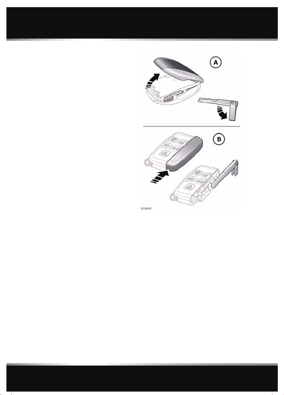
6. Emergency key blade release button.
The vehicle can be unlocked as follow:
A. Press and hold the emergency key release
button (6) while lifting the cover.
Remove and unfold the emergency key
blade.
B. Slide and remove the cover to expose the
emergency key.
6
Page 7

Entering the vehicle
To unlock: Turn the key blade towards the rear
of the vehicle and release. If the security
system is disarmed, all doors and the luggage
compartment will be unlocked. If the security
system is armed, only the front left-hand door
will unlock.
If the vehicle is unlocked using the emergency
key blade with the security system armed, the
alarm will sound when a door is unlocked. To
deactivate the alarm, press the unlock button
on the Jaguar Smart Key or press the engine
START/STOP button with the Smart Key inside
the vehicle.
Replacing the door lock cover:
• Align the cover to engage the bottom two
clips.
• Push the top of the cover to engage the
upper clip.
For the key less locking button (2) operation,
see 12, KEYLESS LOCKING
Insert the key blade into the slot at the base of
the door lock cover (1) and gently lever the key
blade upwards.
Carefully twist the key blade to lever the cover
off the retaining clips.
Insert the key blade into the exposed lock to
operate.
To lock: Ensure all the doors are closed, then
turn the key blade towards the front of the
vehicle and release. This will lock all doors but
will not arm the alarm.
If the Smart Key fails to operate, Smart Key Not
Found- Refer to Handbook is displayed in the
message centre. Whilst the warning is
displayed, hold the smart key close to the
auxiliary switch pack in the position shown.
7
Page 8

Entering the vehicle
KEYLESS ENTRY
Any person fitted with an implanted
medical device should ensure that the
device is kept at a distance of at least
22 cm (8.7 inches) away from any
transmitter mounted in the vehicle.
This is to avoid any possibility of
interference between the system and
device.
For information concerning the
locations of the security system
transmitters, see 173, REMOTE KEY
FOB TRANSMITTER LOCATIONS.
If a remote control is lost, a
replacement can be obtained and
reprogrammed to the vehicle by a
Jaguar Dealer/Authorised Repairer.
Notify a Jaguar Dealer/Authorised
Repairer as soon as a remote control is
lost or stolen and have the remaining
remote control(s) reprogrammed.
Keyless entry allows the vehicle to be unlocked
and disarmed by simply operating the door
handle, provided the Jaguar Smart Key is
within 1.0 m (3 feet).
The Smart Key needs only to be on the driver’s
person; it does not need to be exposed or
handled.
The Smart Key may not be detected if it
is placed within a metal container or if it
is shielded by a device with a back-lit
LCD screen, such as a smart phone,
laptop (including laptop bag), games
console etc. Keep the Smart Key clear of
such devices when attempting Keyless
entry or Keyless starting.
Note: Keyless entry will unlock the vehicle in
accordance with the current security setting
(Single-point or Multi-point entry). However, if
Single-point entry is the current setting and a
door other than the driver’s door is opened
first, all doors will unlock.
When all open doors have been closed, the
system will search the vehicle interior for a
valid Smart Key. If one is not detected, Smart
Key Not Found Place As Shown will be
displayed in the message centre. Find the
Smart Key and place it against the fascia, below
the auxiliary switch pack, as shown previously.
The security system fitted to your vehicle is
Thatcham category 1 approved, and meets EU
regulations 97/116 and EU directive 95/56 EC.
GLOBAL OPENING
Press and hold the unlock button for three
seconds. The vehicle will unlock and the alarm
will be disarmed immediately. After three
seconds, all of the windows will open. This
feature can be enabled/disabled via the
instrument panel menu.
To stop the windows from opening/closing
during the global opening/closing operation,
press any of the buttons on the Jaguar Smart
Key or operate the driver’s window switch. To
stop a particular window from opening,
operate the relevant window switch.
DRIVE-AWAY LOCKING
Locks all the doors when the vehicle exceeds 8
km/h (5 mph). Use of the central locking/
unlocking buttons (see 206, DRIVER
CONTROLS) will override the drive-away
locking feature for the rest of a journey.
If a door is individually unlocked and opened,
all doors will relock when the open door is
subsequently closed.
8
Page 9
Entering the vehicle
Note: Drive-away locking can be enabled/
disabled via the Vehicle Set-up area of the
instrument panel menu.
CONVENIENCE MODE
When the door is opened using either the
Jaguar Smart Key or keyless entry, the
vehicle's electrical system initiates the
convenience mode. The following systems
become functional:
• Driver position memory.
• Seat and steering column adjustment.
• Interior and exterior lighting.
• Message centre.
• Auxiliary power socket.
REMOTE KEY FOB CARE
To prevent accidental operation,
which may result in an injury, never
leave the Jaguar Smart Key in the
vehicle if children or animals are also
left in the vehicle.
Do not expose to extremes of heat, dust,
humidity or allow contact with fluids. Do not
leave the transmitter exposed to direct
sunlight.
The emergency key blade number is recorded
on an attached label. Peel off the label and
attach it to the designated area on the Security
Card, supplied in the literature pack. Keep the
Security Card safe, but not in the vehicle.
The operational range of the Jaguar Smart Key
will vary considerably depending on
atmospheric conditions and interference from
other transmitting devices.
Note: The radio frequency used by the Smart
Key may be used by other devices (e.g. medical
equipment). This may prevent the Smart Key
from operating correctly.
REMOTE KEY FOB BATTERY REPLACEMENT
Note: There are two designs of Smart Key,
refer to the information which is relevant to the
design of Smart Key supplied with the vehicle.
When the battery needs renewing, there will be
a significant decrease in the effective range and
the message SMART KEY BATTERY LOW is
displayed in the message centre.
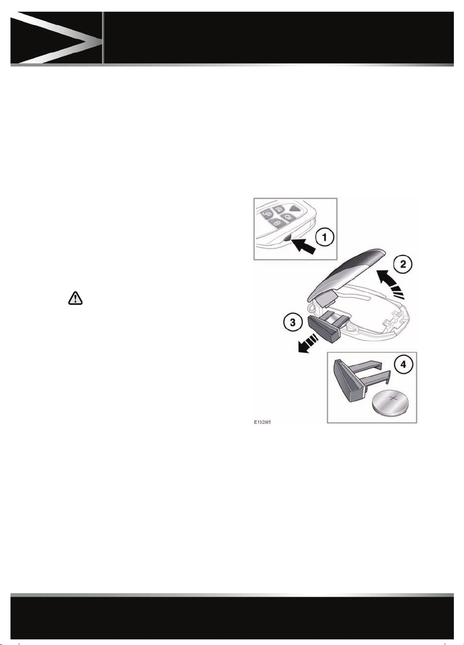
To replace the battery:
1. Press the release button on the side of the
Smart Key.
2. Open the Smart Key cover.
3. Remove the battery drawer.
4. Remove the battery.
Fit a new CR2032 type battery (available from
your Dealer/Authorised Repairer), with the
positive (+) side upwards.
9
Page 10

Entering the vehicle
Replace the battery drawer and close the Smart
key.
To replace the battery:
1. Slide the cover in the direction of the arrow
until a click is heard. Remove the cover.
2. Use the emergency key blade to separate
the Smart Key body.
3. Fit a new CR2032 type battery (available
from your Dealer/Authorised Repairer),
with the positive (+) side upwards.
Note: Avoid touching the new battery, as
moisture/oil from your fingers can reduce
battery life and corrode the contacts.
Refit the parts in the reverse order, ensuring
that they click securely into place.
Battery disposal: Used batteries
must be disposed of correctly, as
they contain harmful substances.
Seek advice on disposal from your
Dealer/Authorised Repairer and/or
your local authority.
10
Page 11
Exiting the vehicle
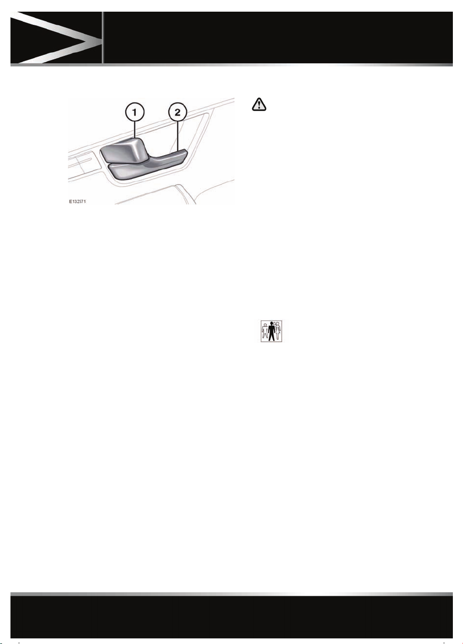
DOOR LOCK AND RELEASE LEVERS
1. Press the locking lever to lock the door,
pull the lever to unlock the door. Operating
the locking lever on either front door will
lock or unlock all closed doors.
2. Pull the release lever to open a door. If a
rear door is locked, operating the lever will
have no effect.
Note: If the car was locked using the Jaguar
Smart Key, then operating the locking lever will
only unlock that door and the alarm will sound.
If the vehicle has been double-locked, the
interior door lock and release levers will not
operate. The vehicle must be unlocked using
the Jaguar Smart Key.
SINGLE LOCKING
Press the lock button briefly. Single locking
secures the vehicle and prevents the doors and
luggage compartment being opened from
outside of the vehicle. The doors can be
unlocked and opened from inside the vehicle.
The hazard warning lamps will flash once as
confirmation.
Exiting the vehicle
DOUBLE LOCKING
Never double lock the vehicle with
people, children or pets inside. In the
event of an emergency they would be
unable to escape, and the emergency
services would be unable to release
them quickly.
When the vehicle is double-locked the
doors cannot be opened, either from
inside or outside the vehicle.
Press the lock button twice within three
seconds. Double locking secures the vehicle
and prevents the doors and luggage
compartment being unlocked or opened from
inside or outside of the vehicle, except with the
correct Jaguar Smart Key. The hazard warning
lamps will flash twice (with a long second
flash) and an audible warning will sound as
confirmation.
The audible warning can be
enabled/ disabled by your
Dealer/Authorised Repairer.
LOCK CONFIRMATION
If you are uncertain whether the vehicle is
locked and armed (either by single or double
locking), press the lock button again. The
hazard warning lights will flash to indicate and
confirm the current lock status.
Note: If the vehicle is not already locked and
armed, pressing the lock button will single lock
the vehicle. Press again to double lock, if
required.
11
Page 12

Exiting the vehicle
MISLOCK
If one of the doors, the hood or the luggage
compartment are not shut fully when the
vehicle is locked using the Jaguar Smart Key or
by Keyless locking, the vehicle will not lock and
two warning tones will sound. Check that all
doors, the hood and the luggage compartment
are closed properly and lock the vehicle again.
If one or more of the doors fails to lock
properly when a lock attempt is made using the
Jaguar Smart Key, two warning tones will
sound and one or more of the doors may not be
locked.
GLOBAL CLOSING
Ensure that no children, pets, or
obstructions are in any open aperture
before operating global closing.
Ensure that all doors are closed, then press and
hold the lock button on the Smart Key for 3
seconds. Alternatively, press and hold the lock
button on the door handle. The vehicle will
single lock and the alarm will be fully armed
immediately. After 3 seconds, all of the
windows will close.
Note: If the button on the door handle is
released before the windows have fully closed,
the windows will stop closing.
KEYLESS LOCKING
Remove all Jaguar Smart Keys and
emergency key blades from the vehicle
when it is left unattended. This will help
prevent the alarm being disarmed and
therefore help prevent theft.
The Smart Key may not be detected if it
is placed within a metal container or if it
is shielded by a device with a back-lit
LCD screen, such as a smart phone,
laptop (including laptop bag), games
console etc.
The vehicle will not lock automatically.
To single-lock the vehicle, press the button on
the door handle once. The hazard warning
lamps will flash once as confirmation (in some
markets, an audible warning will sound).
To double-lock the vehicle, press the button
twice within three seconds. The hazard
warning lamps will flash twice (with a long
second flash). In some markets, a double
audible warning will sound.
Note: Keyless locking will only activate if all
doors, bonnet and the luggage compartment
are closed and the Jaguar Smart Key is outside
the vehicle. If the above conditions are not met,
two audible error warnings will sound.
FULL ALARM
To set full alarm protection, ensure that all the
windows and the sunroof are closed. On
vehicles fitted with double-locking, press the
lock button twice within three seconds. The
hazard warning lights will flash twice to
confirm the alarm state and, in some markets,
an audible tone will sound.
Note: If the alarm is armed and a window or the
sunroof are left open, the alarm may sound due
to movement of air currents, detected by the
intrusion sensors in the front interior light
console.
The intrusion sensors can be temporarily
disabled, for the next time the vehicle is locked,
via the Vehicle Set-up area of the instrument
panel menu.
PERIMETER ALARM
To set perimeter alarm protection, press the
lock button. The hazard warning lights will
flash to confirm the alarm state.
12
Page 13

Exiting the vehicle
BATTERY-BACKED SOUNDER
In certain markets, a separate battery backed
sounder is fitted. This device will sound the
alarm if the vehicle battery or the alarm
sounder is disconnected when the security
system is armed.
DEACTIVATING THE ALARM WHEN TRIGGERED
If the alarm has been triggered, it can be
deactivated by any one of the following
methods:
• Pressing the unlock button on the Jaguar
Smart Key.
• Opening a door using keyless entry.
• Pressing the START/STOP button with a
valid Jaguar Smart Key present.
TILT SENSOR
The tilt sensor detects any change in the
vehicle's angle to the ground. When the alarm
is armed and the vehicle double-locked, any
change in the vehicle's angle will activate the
tilt alarm.
Note: The tilt sensors can be temporarily
disabled, for the next time the vehicle is locked,
via the Vehicle Set-up area of the instrument
panel menu.
PASSIVE ARMING
This vehicle is fitted with a passive arming
feature which can, if enabled, automatically
arm the anti-theft system. Passive arming will
automatically arm the perimeter alarm system
60 seconds after the driver's door is closed,
provided all doors, bonnet and luggage
compartment are closed, the ignition is
switched off and there are no valid Jaguar
Smart Keys inside the vehicle.
Passive arming will not lock the vehicle,
although access to the luggage compartment
via the interior or exterior release buttons will
be prevented and the fuel filler flap will be
locked.
Passive arming can be enabled/
disabled by your
Dealer/Authorised Repairer.
AUTOMATIC RELOCKING AND RE-ARMING OF THE ALARM
Automatic relock and re-arm is a feature which,
if enabled, automatically relocks the vehicle
and arms the anti-theft system.
If the vehicle is in a locked and armed state and
the remote unlock button is pressed, but none
of the doors or the luggage compartment are
opened within 40 seconds, the vehicle will
automatically relock all the doors and the
luggage compartment and will re-arm the
alarm system.
Note: Automatic relocking and arming will only
relock and arm to the last locked and armed
state.
Automatic relocking and
re-arming can be enabled/disabled
by your Dealer/Authorised
Repairer.
SENSOR FAULTS
If the security systems detect a fault with one
of the security sensors, an error tone will
sound from the alarm after the vehicle is
unlocked and disarmed. If this condition
occurs, please visit your Dealer/Authorised
Repairer for rectification.
13
Page 14

Front seats
Front seats
ELECTRIC SEATS
14
Page 15
Front seats
1. Cushion length adjustment.
2. Bolster adjustment (inflate/deflate).
3. Lumbar support adjustment.
4. Seat back angle adjustment.
5. Head restraint height adjustment.
6. Height adjustment.
7. Forward and rearward adjustment.
8. Cushion front tilt adjustment.
To adjust the seats, the Jaguar Smart Key must
be in the vehicle and the ignition turned on.
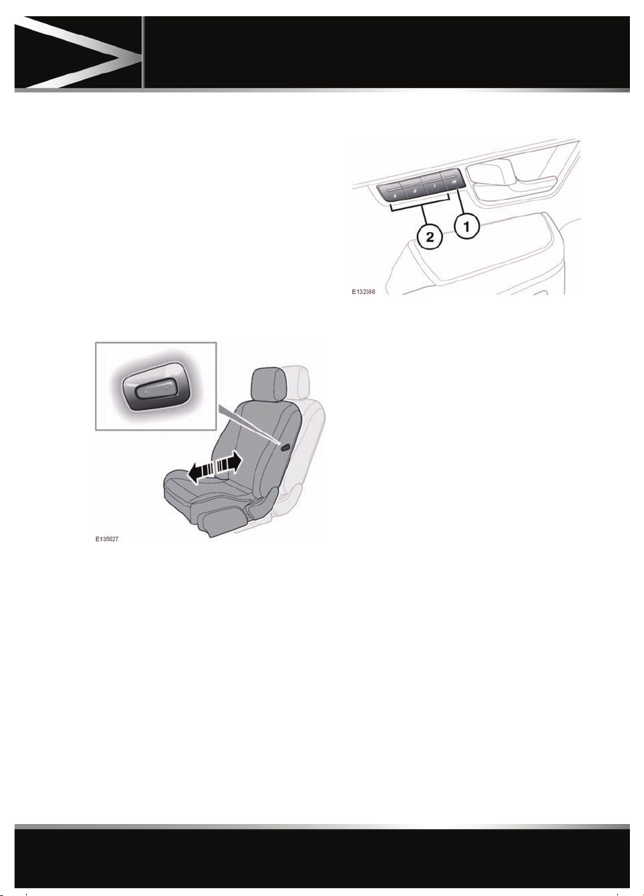
PASSENGER SEAT AWAY
When fitted the driver can adjust the position of
the front passenger seat, press for forward or
rearward adjustment.
DRIVING POSITION MEMORY
1. Memory set button.
2. Memory presets.
Once you have adjusted the driver's seat,
steering column (21, ADJUSTING THE
STEERING WHEEL) and exterior mirrors (41,
EXTERIOR MIRRORS) the vehicle can
memorise these settings using the driver
memory buttons.
Once the passenger seat has been adjusted,
these settings can be memorised using the
passenger memory buttons.
1. Press the memory set button to activate
the memory function.
2. Press one of the preset buttons within five
seconds to memorise the current settings.
For the driver’s settings, MEMORY 1 (2 or
3) SETTINGS SAVED will be displayed on
the message centre accompanied by an
audible chime to confirm the settings have
been memorised.
A seat position can only be memorised during
the five second period.
Any existing settings for a memory preset will
be over-written when programming a memory
position.
15
Page 16

Front seats
RECALLING A MEMORISED POSITION
Press the appropriate memory preset button
(for the driver’s settings, MEMORY 1 (2 or 3)
SETTINGS RECALLED will be displayed in the
message centre).
RESTRICTED SEAT TRAVEL
If an obstruction is encountered while the seat
is in motion, the seat will stop moving and
further movement will be restricted until reset.
To reset the seat:
1. Remove the obstruction.
2. Adjust the seat to the point where
movement is restricted.
3. Press and hold the switch for at least 2
seconds to override the restriction.
SITTING IN THE CORRECT POSITION
The seat, head restraint, seat belt and airbags,
all contribute to the protection of the user.
Correct use of these components will give you
greater protection, therefore you should
observe the following points:
1. Sit in an upright position with the base of
your spine as far back as possible and the
seat back reclined no more than 30
degrees, to achieve optimum benefit of the
seat belt in the event of an accident.
2. Do not move the driver's seat too close to
the steering wheel. Ideally, a minimum
distance of 254 mm (10 inches) is
recommended between the breastbone
and the steering wheel airbag cover. Hold
the steering wheel in the correct position
with your arms slightly bent.
• Adjust the head restraint so that the top of
the head restraint is above the centre line of
the head.
• Position the seat belt so that it is mid-way
between your neck and your shoulder. Fit
the strap tightly across your hips, not
across your stomach.
• Ensure that your driving position is
comfortable and enables you to maintain
full control of the vehicle.
The driver and front passenger must
not ride with the seat fully reclined.
Do not adjust the seat while the
vehicle is moving.
16
Page 17
Rear seats
Rear seats
ELECTRIC SEATS
Note: This feature will not operate if the rear
window isolation switch has been activated.
To adjust the seats, the Jaguar Smart Key must
be in the vehicle and the ignition turned on.
REAR SEAT SAFETY
Never allow passengers to travel in
the luggage compartment under any
circumstances.
All vehicle occupants should be
seated correctly, and wear a seat belt
at all times when the vehicle is in
motion.
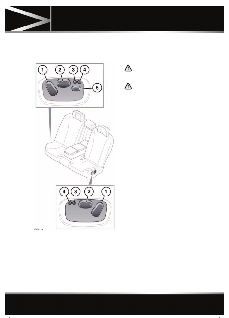
1. Seat back angle adjustment.
2. Lumber support adjustment.
3. Massage OFF.
4. Massage ON, operates for 10 minutes or
until switched off.
5. Front passenger seat away, forward or
rearward adjustment.
17
Page 18
Head restraints
Head restraints
FRONT HEAD RESTRAINTS
Adjust the head restraint so that the
top of the head restraint is above the
centre line of the head. An incorrectly
adjusted head restraint increases the
risk of death or serious injury in the
event of a collision.
It is posible to swivel the head
restraint forwards or backwards. For
greater protection in the event of a
collision, the head restraint should be
adjusted so that it is as close to the
back of the head as is practical.
Never adjust the head restraint while
the vehicle is in motion.
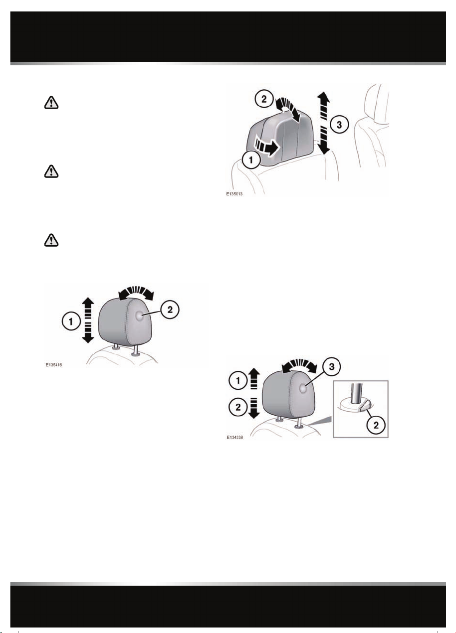
ELECTRIC FRONT HEAD RESTRAINTS
1. Pull the wing heads forward in to the first
or second position.
2. Rotate the head restraint to adjust the
angle.
Note: There is no angle adjustment on
headrests where a DVD screen is fitted.
3. To adjust the height of the head restraint,
see 14, ELECTRIC SEATS
Note: It is not possible to remove the electric
front head restraints.
1. To adjust the height of the head restraint,
see 14, ELECTRIC SEATS
2. To adjust the angle of the head restraint,
press the locking button on the side of the
restraint and tilt to the desired position.
Note: There is no angle adjustment on
headrests where a DVD screen is fitted.
18
MANUAL FRONT HEAD RESTRAINTS
1. To raise, pull the restraint upwards, it will
click and lock in position.
Note: Do not try to raise the head restraint
further than the third adjustment position.
2. To lower, depress the locking button and
push down on the restraint.
3. To adjust the angle of the head restraint,
press the locking button on the side of the
restraint and tilt to the desired position.
Page 19
Note: The head restraint can only be removed
if the seat is moved forward or back to create
more space.
To remove the head restraint, adjust the angle
of the back of the seat forward or back to create
more space. Press both locking buttons at the
same time and lift the restraint out of the seat.
Always store a removed head restraint
securely.
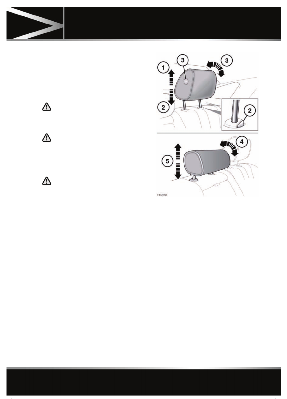
REAR HEAD RESTRAINTS
It is possible to swivel the head
restraint forwards or backwards. For
greater protection in the event of a
collision, the head restraint should be
adjusted so that it is as close to the
back of the head as is practical.
Do not drive or carry passengers with
the head restraint removed from an
occupied seat. The absence of a
correctly adjusted head restraint
increases the risk of neck injury in the
event of a collision.
Head restraints
1. To raise, pull the restraint upwards, it will
click and lock in position.
2. To lower, depress the locking button and
push down on the restraint.
3. To adjust the angle of the head restraint,
press the locking button on the side of the
restraint and tilt to the desired position.
4. To adjust the centre head restraint, tilt the
restraint forward.
5. Raise or lower the restraint as required.
The head restraint can be locked in one of
three height positions.
Note: Do not use the locking collars to raise or
lower the centre head restraint.
19
Page 20
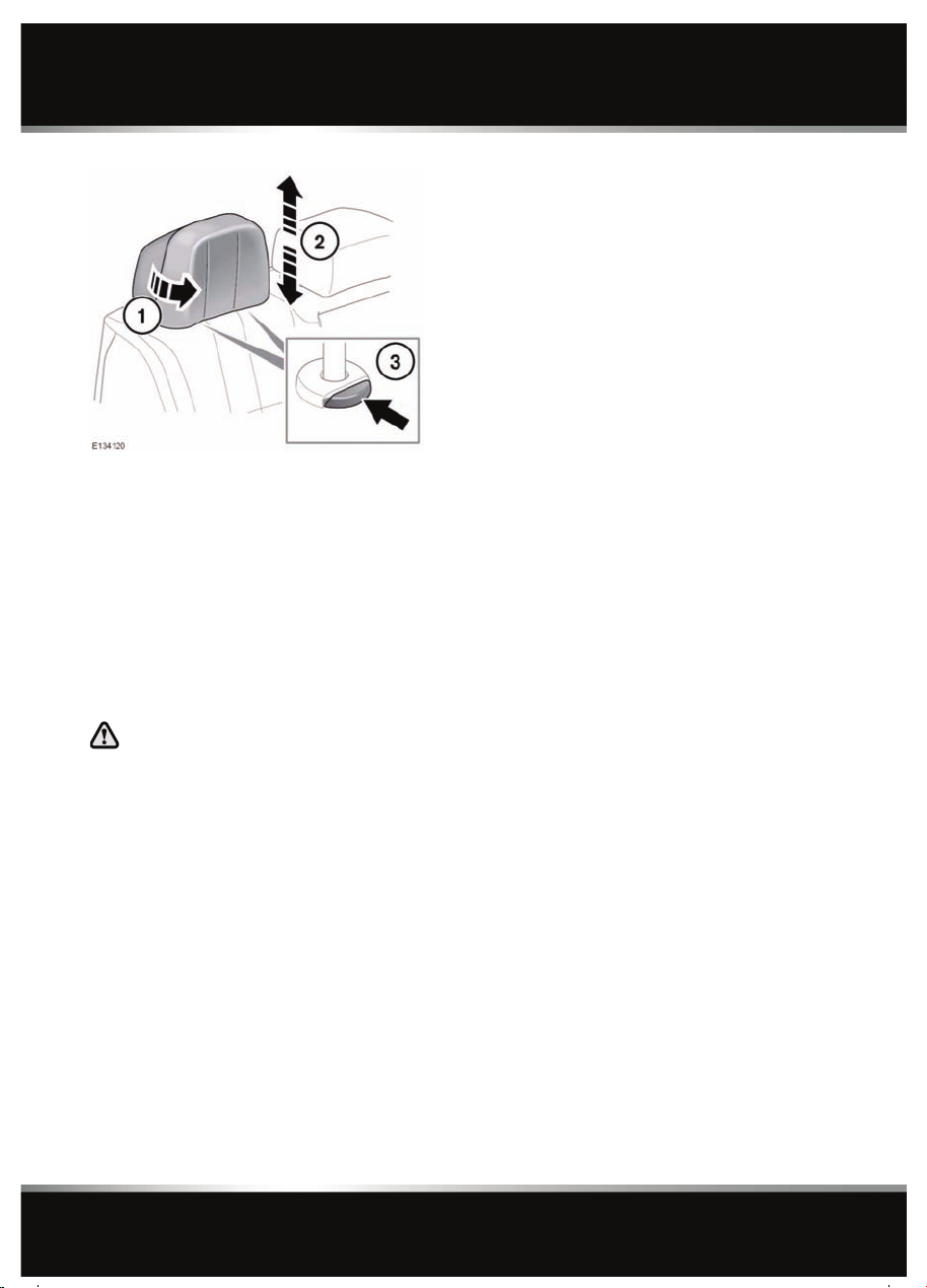
Head restraints
1. Pull the wing heads forward in to the first
or second position.
2. To raise, pull the restraint upwards, it will
click and lock in only one position.
Note: Do not try to raise the head restraint
further than the one adjustment position.
3. To lower, depress both the locking buttons
at the same time.
HEAD RESTRAINT REMOVAL
Always store a removed head restraint
securely.
It is possible to remove the centre rear head
restraint, if necessary, to enable the fitment of
a child restraint:
1. Raise the head restraint to its uppermost
position.
2. Press both locking collars.
3. Lift the head restraint out of the seat.
Ensure the head restraint is refitted once the
child seat is removed.
Note: It is not possible to remove the left or
right rear head restraints.
20
Page 21
Steering wheel
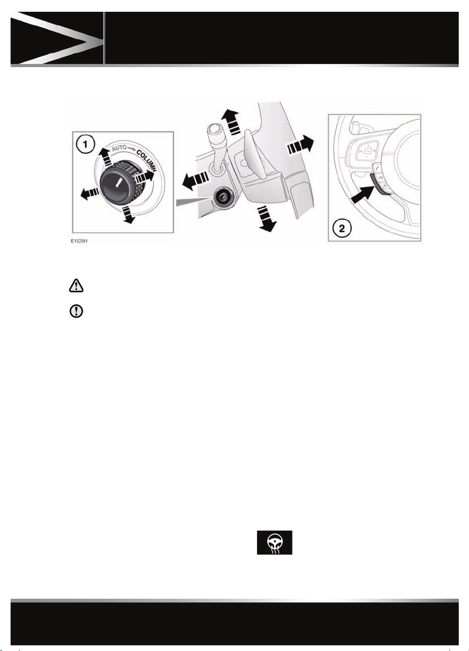
ADJUSTING THE STEERING WHEEL
Steering wheel
1. Steering column adjuster.
2. Heated steering wheel switch.
Never adjust the steering wheel whilst
the vehicle is moving.
Do not use steering wheel mounted
security devices. Movement of the
steering wheel in exit and entry mode,
could result in damage to the vehicle or
possible injury to the occupant.
The steering wheel can be adjusted for tilt and
reach as follows:
• Move the control forwards or rearwards to
adjust reach.
• Move the switch up or down to adjust tilt.
Up to 3 steering wheel positions can be stored
and recalled, along with seat and exterior
mirror positions, by the driving position
memory. See 15, DRIVING POSITION
MEMORY.
ENTRY AND EXIT MODE
With the steering column adjustment control in
the AUTO position, the steering column will
move to provide easier entry and exit from the
vehicle, as follows:
• Exit: When the driver’s door is opened, the
steering column will move to the
uppermost tilt position.
• Entry: When the driver’s door is closed and
the ignition is turned on, the steering
column will return to its previously
selected driving position.
Note: If the column control is moved away
from AUTO when the column is in the Exit
position, the column will still move back to its
previous driving position when the driver’s
door is closed and the ignition is switched on.
Note: If the column is manually adjusted
during Entry or Exit operation, column
movement will stop.
HEATED STEERING WHEEL
Press this switch (2) to activate
the steering wheel heater. Press
again to turn off.
21
Page 22

Occupant safety
Occupant safety
USING SEAT BELTS AND CHILD SAFETY LOCKS
22
Page 23
Occupant safety
1. If children are to be carried in the rear seat
positions, it is recommended that the rear
door interior handles are disabled. To
change the child lock settings:-
• Open the door to access the child
safety lock.
• Insert the emergency key into the slot
and rotate a quarter of a turn, to enable
or disable the interior door handle, as
required.
2. To install an ISOFIX child seat (not
Australia):-
• Raise the head restraint on the relevant
seat.
• Locate the lower anchor bars which are
accessible through the gap between
the seat back and seat base. Insert the
protective guides supplied with the
child seat as shown. The insertion
positions for the guides are identified
by the ISOFIX labels.
• Slide the child seat locking mechanism
into the protective sleeves and onto the
anchor bars.
• Test the security of the child restraint.
To do this, attempt to pull the restraint
away from the vehicle seat and twist
the restraint from side to side. Even if
the restraint appears secure you
should always check the anchor points
visually to ensure correct attachment.
Note: Always ensure that if an upper tether
is provided, it is fitted and tightened
correctly.
3. To adjust the seat belt height:-
• Press to release the catch.
• With the catch depressed slide the
mechanism up or down to the required
height. Release the catch and ensure
the locking mechanism has engaged.
The use of comfort clips or devices
that would create slack in the seat
belt system, is not advised.
No modifications or additions
should be made by the user which
will either prevent the seat belt
adjusting devices from operating
to remove slack, or prevent the
seat belt assembly from being
adjusted to remove slack.
4. Draw the belt out smoothly, ensure that the
belt height, the seat, and your position on
the seat are correct.
Seat belts are designed to bear
upon the bony structure of the
body, and should be worn low
across the front of the pelvis or the
pelvis, chest and shoulders, as
applicable; wearing the lap
section of the belt across the
abdominal area must be avoided.
Seat belts should be adjusted as
firmly as possible, consistent with
comfort, to provide the protection
for which they have been
designed. A slack belt will greatly
reduce the protection afforded to
the wearer.
Belts should not be worn with the
straps twisted.
Each belt assembly must only be
used by one occupant; it is
dangerous to put a belt around a
child being carried on the
occupant's lap.
The occupants of the front seats
should not travel with the seat
back at more than 30 degrees from
upright. Doing so will reduce the
protection afforded by the seat
belt.
23
Page 24

Occupant safety
Never place anything between you
and the seat belt in an attempt to
cushion the impact in the event of
an accident.
5. With the seat belt correctly positioned,
place the metal tongue into the buckle
nearest to you. Press it in until a click is
heard. Ensure that all slack has been taken
up by the retractor and the belt fits tightly
across the hips.
Note: When releasing the seat belt it is
advisable to hold the belt before pressing
the release button. This will prevent the
belt from retracting too quickly.
To release the seat belt, press the red
button.
6. Use of seat belts during pregnancy:
Position the lap strap comfortably across
the hips beneath the abdomen. Place the
diagonal part of the seat belt between the
breasts and to the side of the abdomen.
Position the seat belt correctly for
the safety of the mother and
unborn child. Never wear just the
lap strap, and never sit on the lap
strap whilst using just the
shoulder strap.
Never place anything between you
and the seat belt. It can be
dangerous and reduce the
effectiveness of the seat belt in
preventing injury.
Ensure that the seat belt is not
slack or twisted.
7. Tether strap anchorages. See 28,
INSTALLING TETHER ANCHORAGE CHILD
RESTRAINTS.
Child restraint anchorages are
designed to withstand only those
loads imposed by correctly fitted
child restraints. Under no
circumstances are they to be used
for adult seat belts, harnesses or
for attaching other items or
equipment to the vehicle.
If a child seat or restraint system
is to be fitted to the centre seating
position, the centre armrest must
be in the stowed position (folded
into the seat).
Note: A tether anchorage is provided for
the centre seat position. Do not use this
anchor position with an ISOFIX child seat.
SEAT BELT SAFETY
Care should be taken to avoid
contamination of the webbing with
polishes, oils and chemicals, and
particularly battery acid. Cleaning
may safely be carried out using mild
soap and water.
The belt should be replaced if
webbing becomes frayed,
contaminated or damaged.
It is essential to replace the entire
assembly after it has been worn in a
severe impact, even if damage to the
assembly is not obvious.
Do not carry hard, fragile or sharp
items between your person and the
seat belt.
Seat belts should be worn by all
vehicle occupants, for every journey,
no matter how short.
When using seat belts to restrain
items other than occupants, take care
to ensure that the belts are not
damaged, or exposed to sharp edges.
24
Page 25
Occupant safety
The use of comfort clips, or devices
that would create slackness in the
seat belt system, is not advised.
SEAT BELT CHECKS
Note: If the vehicle is parked on an incline, the
seat belt mechanism may lock. This is a safety
feature and the belt should be gently eased out
from the upper anchorage.
The seat belts should be inspected regularly to
check for fraying, cuts or wear to the webbing,
and the condition and security of the
mechanism, buckles, adjusters, and mounting
points.
• With the seat belt fastened, give the
webbing near the buckle a quick upward
pull. The buckle must remain securely
locked.
• With the seat belt unfastened, unreel the
seat belt to the limit of its travel. Check that
it unreels smoothly with no snatches or
snags. Allow the belt to fully retract, again
checking for smooth operation.
• Partially unreel the seat belt, then hold the
tongue plate and give a quick forward pull.
The mechanism must lock and prevent any
further unreeling.
If any of the seat belts fail to meet those
criteria, immediately contact your Dealer/
Authorised Repairer.
SEAT BELT WARNING LAMP
The warning lamp in the
instrument panel stays illuminated
when the driver’s or front
passenger’s seat belt is not
fastened (if the passenger seat is
occupied). The lamp should
extinguish when the seat belt is
fastened.
The warning lamp will also flash in conjunction
with the Beltminder warning chime.
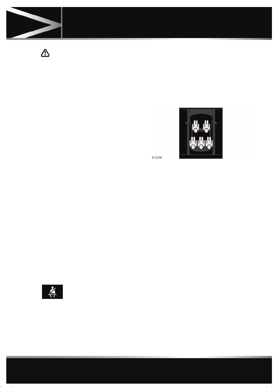
BELTMINDER
A front and rear seat Beltminder system warns
the driver when the seat belt of an occupied
seat is not fastened or is unfastened during a
journey.
A graphic in the message centre indicates
which seat belts are fastened at the start of a
journey and also when a seat belt is fastened or
unfastened during a journey.
Each seating position is represented by a
passenger icon, the colour of which indicates
the seat belt status:
• No colour - seat belt not fastened.
• Green - seat belt fastened.
• Red - driver’s or occupied front seat
passenger’s seat belt is not fastened or is
unfastened during a journey.
In addition, an audible warning will sound
under the following conditions:
• The driver’s or occupied front seat
passenger’s seat belt is not fastened or is
unfastened during a journey.
• A rear seat belt is unfastened.
Note: If a heavy object is placed on the front
passenger seat, it may activate the Beltminder
feature. It is recommended that the object be
placed in the luggage compartment or secured
using the seat belt.
25
Page 26
Occupant safety
Note: Although not advisable, it is possible to
disable the Beltminder function. Please see
your Dealer/Authorised Repairer to disable or
re-instate the function.
CHILD SEATS
For optimum safety, children should
travel in the rear of the vehicle at all
times; front passenger seat travel is
not recommended. However, if it is
essential that a child travels in the
front, set the vehicle seat fully
rearward and seat the child in an
approved forward-facing child seat.
Do not use a rear-facing child seat - an
inflating airbag could impact with the
seat and cause serious injury.
Do not use a forward facing child seat
until the child using it is above the
minimum weight of 9 kg (20 lb.) and
able to sit up unaided. Up to the age of
two, a child's spine and neck are not
sufficiently developed to avoid injury
in a frontal impact.
Do not allow a baby or infant to be
held or carried on the lap. The force of
a crash can increase effective body
weight by as much as thirty times,
making it impossible to hold onto the
child.
Children typically require the use of a
booster seat appropriate to their age
and size, thereby enabling the seat
belts to be properly fitted, reducing
the risk of injury in a crash. Children
could be endangered in a crash if their
child restraints are not properly
secured in the vehicle.
Do not use a child seat that hooks over
the seat back. This type of seat cannot
be satisfactorily secured and is
unlikely to be safe for your child.
The seat belts fitted to your vehicle are
designed for adults and larger children. It is
very important for all infants and children
under 12 years of age to be restrained in a
suitable child safety seat appropriate to their
age and size.
If it is essential that a child travels in the front
passenger seat (and national legislation
permits this), Jaguar recommends that the
following preparations are made before fitting
the child restraint.
• Adjust the front passenger seat fully
rearwards.
• Adjust the lumbar support to its minimum
support position.
• Adjust the seat cushion to its highest
position. If cushion front tilt adjustment is
possible, adjust it to its lowest position.
• Adjust the seat back to the fully upright
position.
• Adjust the seat belt adjustable upper
anchorage to its lowest position.
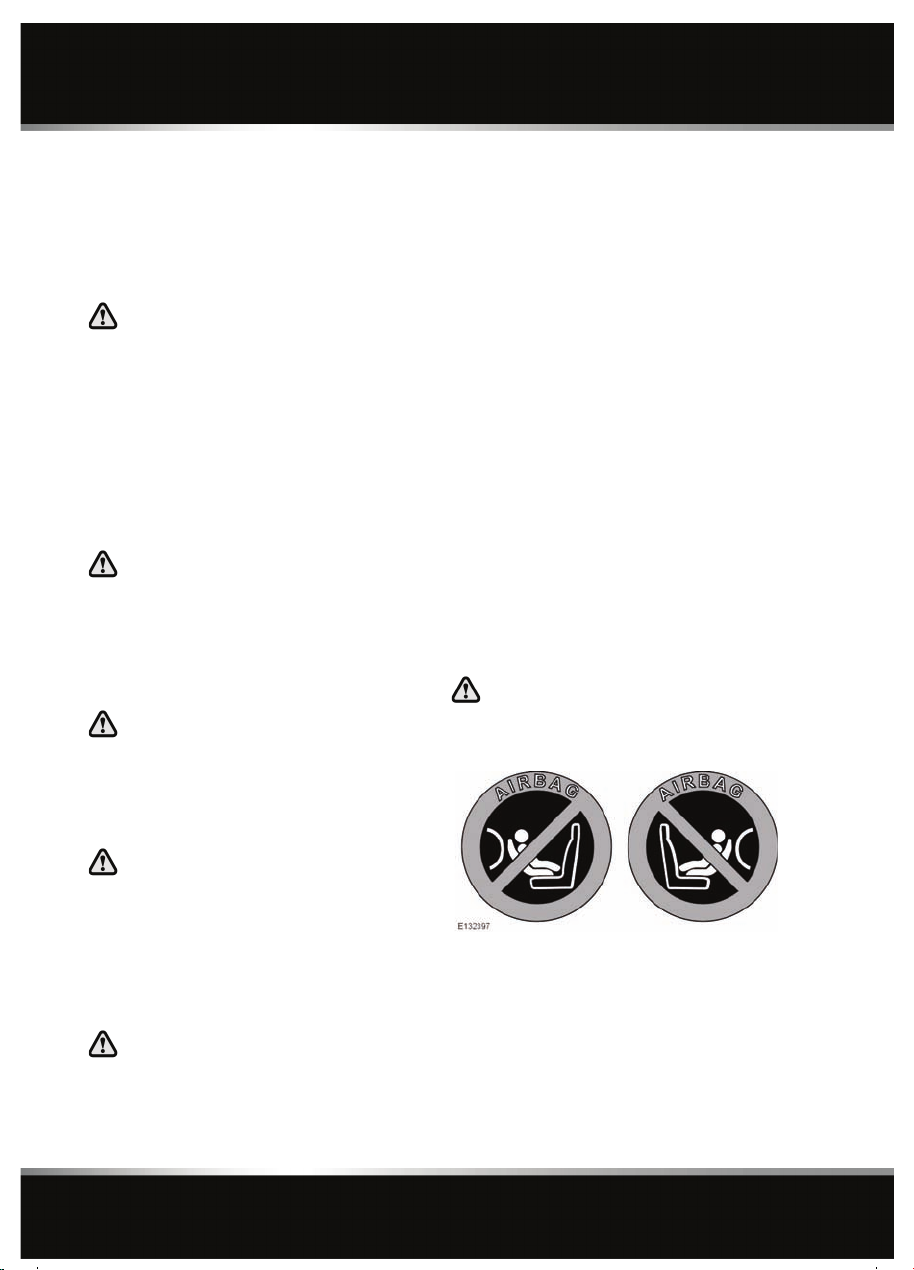
Extreme hazard! Do not use a
rearward facing child restraint on a
seat protected by an airbag in front of
it.
This symbol, affixed to the end of the fascia on
the passenger side, warns against the use of a
rear-facing child seat in the front passenger
seat, when a front passenger airbag is fitted
and operational.
26
Page 27
Occupant safety
CHILD RESTRAINT CHECK LIST
Every time a child travels in the vehicle observe
the following:-
• Use appropriate child restraints.
• Carefully follow the restraint system
manufacturers instructions.
• Adjust the harnesses for every child on
every trip.
• Ensure that all slack is removed from the
adult seat belt.
• Always attach the top tether when
installing an ISOFIX seat.
• Always check the security of the child
restraint.
• Do not dress a child in bulky clothing, or
place any objects/padding between the
child and the restraint.
• Regularly check the fit and condition of
child restraints. If the fit is poor, or
wear/damage is visible replace the restraint
immediately.
• Set a good example - always wear your
seat belt.
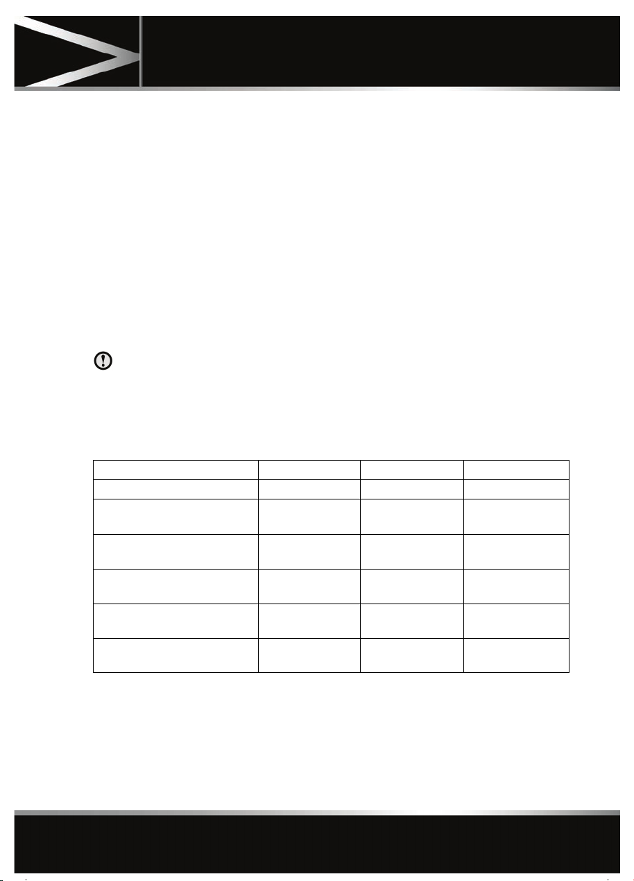
CHILD SEAT POSITIONING
Information given within the table is
correct at the time of going to press.
However, availability of child restraints
may change. Please consult your
Dealer/ Authorised Repairer for the
latest recommendation.
Seating positions Front passenger* Rear outboard Rear centre
Mass group
0 = Up to 10 kg (22 lb.) 0 to 9
months
0+ = Up to 13 kg (29 lb.) 0 to 18
months
I = 9 to 18 kg (20 to 40 lb.) 9
months to 4 years
II = 15 to 25 kg (33 to 55 lb.) 4
to 9 years
III = 25 to 36 kg (55 to 80 lb.) 8
to 12 years
UF U U
Note: The information contained in the
following table may not be applicable to all
countries. If you are in any doubt regarding the
type and fitment of child seats seek advice from
your Dealer/Authorised Repairer.
XU U
XU U
UU U
UU U
• U = Suitable for universal category
restraints approved for this mass group.
• UF = Suitable for forward facing Universal
category restraints approved for this mass
group.
• X = Not suitable for child restraint fitment
in this mass group.
27
Page 28
Occupant safety
* Jaguar recommend that the front passenger
seat be positioned fully rearward, with the
cushion adjusted to the highest position when
installing child restraints.
Note: Ages given are approximate. In case of
doubt, the child’s weight, not age, should be
used when considering an appropriate child
seat.
BOOSTER CUSHIONS
In a situation where a child is too large to fit
into a child safety seat, but is still too small to
safely fit the three point belt properly, a booster
seat is recommended for maximum safety.
Follow the manufacturer's instructions for
fitting and use, then adjust the seat belt to suit.
INSTALLING TETHER ANCHORAGE CHILD RESTRAINTS
1. Install the child restraint securely in one of
the rear seating positions.
2. Pass the tether strap over the seat back and
beneath the head restraint.
3. Attach the tether strap hook to the tether
anchor point on the back of the seat.
Ensure that the tether strap hook is facing
the correct way. See 22, USING SEAT
BELTS AND CHILD SAFETY LOCKS.
4. Tighten the tether strap according to the
manufacturer's instructions.
If the restraint is not correctly
anchored, there is a significant risk of
injury to the child in the event of a
collision or emergency braking.
Child restraint anchorages are
designed to withstand only those
loads imposed by correctly fitted child
restraints. Under no circumstances
are they to be used for adult seat
belts, harnesses or for attaching other
items or equipment to the vehicle.
If removing the centre head restraint
in order to fit a child restraint, always
secure the head restraint when storing
it.
Both of the outer rear seat positions are
equipped to accept ISOFIX restraints.
This symbol is shown on a label
sewn into the seats to indicate the
position of the ISOFIX lower
anchorages.
ISOFIX ANCHOR POINTS (not Australia)
Do not attempt to fit ISOFIX restraints
to the centre rear seating position.
The anchor bars are not designed to
hold an ISOFIX restraint in this
position.
28
Page 29

Occupant safety
Note: The information contained in the
following table may not be applicable to all
countries. If you are in any doubt regarding the
type and fitment of child seats seek advice from
your Dealer/Authorised Repairer.
Mass group Size classes Fixtures Rear outboard seats
Carrycot F/G ISO L1/L2 X
0 = Up to 10 kg (22 lb.) 0 to 9
months
0+ = Up to 13 kg (29 lb.) 0 to
18 months
I = 9 to 18 kg (20 to 40 lb.) 9
months to 4 years
II = 15 to 25 kg (33 to 55 lb.)
4 to 9 years
III = 22 to 36 kg (49 to 80 lb.)
8 to 12 years
• IUF = Suitable for ISOFIX forward child
restraint systems of universal category
approved for use in the mass group.
• IL = These ISOFIX child restraint systems
are of the specific vehicle, restricted or
semi-universal categories.
• X = Not suitable for child restraint fitment
in this mass group.
• * = Child seat suitable for use in these
locations is the Britax/Römer Baby Safe
Plus.
Note: Ages given are approximate. In case of
doubt, the child’s weight, not age, should be
used when considering an appropriate child
seat.
EISO R1 IL*
C/D/E ISO R1/R2/R3 IL*
C/D
A/B1/B
-N/AN/A
-N/AN/A
ISO R2/R3
ISO F2/F2X/F3
X
IUF
29
Page 30
Occupant safety
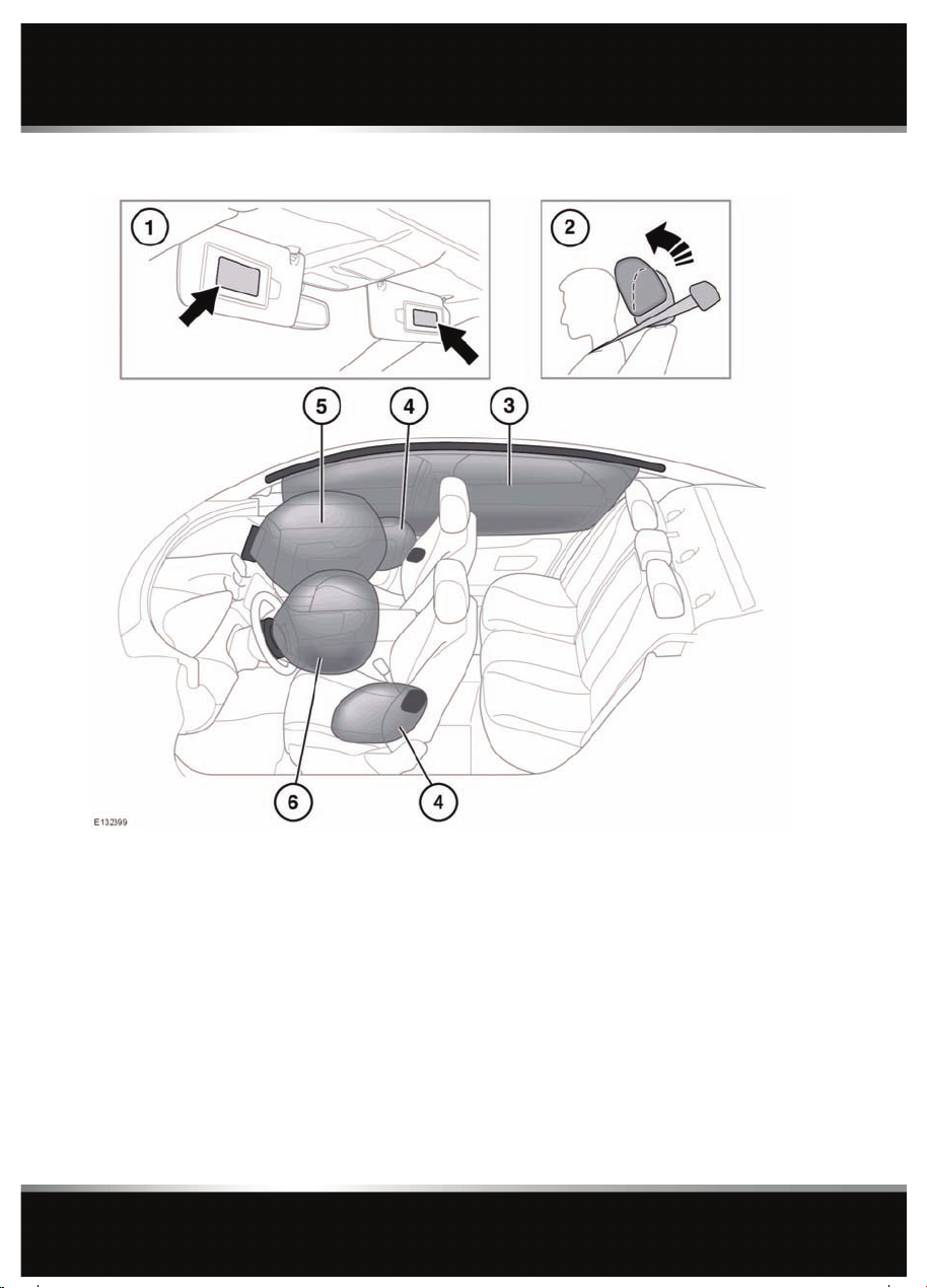
AIRBAGS AND ACTIVE HEAD RESTRAINTS
1. Airbag warning information is printed on
the driver and passenger sun visors.
2. Both front seats are equipped with Active
Head Restraints (AHR) which reduce the
risk of neck and spinal injury (whiplash) in
the event of a rear impact by moving the
head restraint upwards and forwards,
supporting the occupant’s head.
After activation, the whiplash protection
mechanism resets automatically and does
not need to be replaced.
30
3. The curtain airbags may deflate at a slower
rate than the front or side airbags, to afford
prolonged protection.
4. Seat mounted side airbags.
5. Front passenger airbag.
6. Driver’s airbag.
Note: The general location of airbags fitted to
the vehicle are marked by the word AIRBAG.
Always contact your Dealer/Authorised
Repairer if:
• An airbag inflates.
Page 31

Occupant safety
• The front or sides of the vehicle are
damaged.
• Any part of the Airbag Supplementary
Restraint System (SRS) shows signs of
cracking or damage, including trim
covering airbags.
AIRBAG OPERATION
For the airbags to operate correctly
the roof lining and door post trims
must be in good condition, correctly
fitted, and free from obstruction. Any
damage, wear, or incorrect fitment
should be referred to your
Dealer/Authorised Repairer as soon
as possible for examination and
repair.
Do not obstruct the operation of the
airbags by placing any part of their
person or any objects in contact with,
or close to, an airbag module. Only
use approved accessories (e.g. seat
covers).
Ensure that a gap is maintained
between the side of the vehicle, and
the head and torso. This will enable
unobstructed inflation of the curtain,
and seat mounted side airbags.
Airbags inflate at high speeds. To
minimise the risk of injury, ensure
that all vehicle occupants wear
correctly positioned seat belts, sit
correctly in the seats, and position the
seats as far back as practical.
Airbag inflation takes place
instantaneously, and cannot protect
against the effects of secondary
impacts. Under these circumstances
the only protection will be provided by
a correctly worn seat belt.
Phone systems should only be
installed by qualified persons familiar
with the operation of, and
requirements for, vehicles fitted with
SRS. If you are in any doubt, seek
advice from your Dealer/Authorised
Repairer.
Airbag deployment is dependent on the rate at
which the passenger compartment changes
velocity following the collision. Circumstances
affecting different collisions (vehicle speed,
angle of impact, type and size of object hit,
etc.), vary considerably and will affect the rate
of deceleration accordingly.
The Supplementary Restraint System (SRS)
components include:-
• SRS warning indicator.
• Rotary coupler.
• Airbag modules.
• Seat belt pre-tensioners (front seat belts).
• Airbag diagnostic control unit.
• Crash sensors.
• Airbag wiring harnesses.
The SRS is not designed to operate as a result
of:
• Rear impacts.
• Minor front impacts.
• Minor side impacts.
• Heavy braking.
• Driving over bumps and pot holes.
Therefore, it follows that considerable
superficial damage to the vehicle can occur,
without causing the airbags to deploy.
31
Page 32

Occupant safety
AIRBAG DEPLOYMENT EFFECTS
When an airbag inflates, a fine
powder is released. This is normal
and not an indication of a malfunction.
The powder may cause irritation to the
skin and should be thoroughly flushed
from eyes and any cuts or abrasions.
Airbag deployment is accompanied by
a very loud noise which may cause
discomfort and temporary loss of
hearing.
AIRBAG WARNING LAMP
The airbag warning indicator is
mounted in the instrument panel,
and will illuminate as a bulb check
when the ignition is switched on.
If the warning indicator signals that a
fault is present in the system, do not
use a child restraint on the front
passenger seat.
If any of the following warning indicator
conditions occur, the vehicle should be
checked by your Dealer/Authorised Repairer
immediately.
• The warning indicator fails to illuminate
when the START/STOP button is initially
switched on.
• The warning indicator fails to extinguish
within six seconds of the START/STOP
button being switched on.
• The warning indicator illuminates at any
time other than during the bulb check.
AIRBAG SERVICE INFORMATION
Do not attempt to service, repair,
replace, modify, or tamper with, any
part of the SRS. This includes wiring
or components in the vicinity of SRS
components. Doing so may cause the
system to trigger, or render the
system inoperative.
Do not use any electrical test
equipment or devices in the vicinity of
SRS components or wiring. Doing so
may cause the system to trigger, or
render the system inoperative.
All of the following operations should only be
carried out by a Dealer/Authorised Repairer, or
suitably qualified person:-
• Removal or repair of any wiring or
component in the vicinity of any SRS
components.
• Installation of electrical, or electronic,
equipment and accessories.
• Modification to the front or sides of the
vehicle exterior.
• Attachment of accessories to the front or
sides of the vehicle.
32
Page 33

Exterior lights
LIGHTING CONTROL
Exterior lights
1. With the headlamps on, push the switch
away from the steering wheel to select high
beam. The blue warning indicator on the
instrument panel will illuminate.
2. Pull the switch towards the steering wheel
and release to flash the high beam on and
off. The high beam will remain on for as
long as the switch is held.
3. Side lights.
4. Low beam.
5. When ambient light fades the side lights
and headlamps will switch on
automatically.
6. Exit delay of 30 seconds.
7. Exit delay of 60 seconds.
8. Exit delay of 120 seconds.
Note: If the rotary control is in the AUTO
position there will be no exit delay and the
headlamps will extinguish when the ignition
system is turned off.
Press the headlamp button on the Jaguar
Smart Key to switch off the headlamps during
an exit delay period.
If the rotary control is moved to the OFF
position, with high beam still activated, both
low and high beam will be extinguished. Both
low and high beam will illuminate when the
headlamps are turned on again.
DIRECTION INDICATORS
In addition to normal operation, the indicators
will operate 3 times (e.g. to indicate a lane
change) if the stalk is briefly pushed up or
down.
DAYLIGHT RUNNING LAMPS
In some countries, with the rotary control in
the OFF or AUTO position, low beam
headlamps, side lamps, tail, number plate
lamps and, where fitted, side marker lamps will
switch on automatically with the following
conditions:
• The ignition is on.
• The gear selector is out of park.
• The parking brake is not applied (is
released) - market dependent.
33
Page 34

Exterior lights
APPROACH LAMPS
The headlamps can be illuminated remotely for
a programmed length of time, by pressing the
headlamp button on the Jaguar Smart key. See
5, UNLOCKING THE VEHICLE. Press the button
again to switch off.
Note: In some markets, a second press will
illuminate the reverse lamps and a third press
is required to turn the lamps off.
ADAPTIVE FRONT LIGHTING SYSTEM (AFS)
Adaptive front lighting is designed to give the
driver improved visibility, using a swivelling
headlamp unit, a static bending lamp and a
cornering lamp. These lamps broaden the
beam of the headlamps when cornering in
different circumstances.
The headlamp unit swivels accordingly when
cornering, to improve light spread on bends in
the road.
Static bending lamps: The static bending
lamps operate when necessary, to provide an
even broader light spread.
Cornering lamps: At speeds up to 40 km/h (25
mph), to provide improved visibility at
junctions, the system switches on the lamp if it
has received an input from the vehicle's
direction indicator. Only the lamp on the same
side as the operating indicator illuminates. The
lamp will self cancel after 3 minutes of
continuous operation.
WINDSCREEN WIPER DETECTION
This function only operates when autolamps is
selected. The side lamps, tail lamps and
headlamps will switch on automatically if the
windscreen wipers are switched on for 20
seconds or more. Once the windscreen wipers
are switched off, the side lamps and headlamps
will automatically switch off two minutes later.
AUTO HIGH BEAM
This feature automatically selects and
deselects high beam, under specific conditions
of road lighting and in the absence of other
vehicle’s lights. The system is only active when
the ambient light drops below a predetermined
level.
This function is only active if the rotary control
is in the AUTO position and the stalk is in the
central position.
The system will only activate when vehicle
speed exceeds 25 mph (40 km/h). The system
will deactivate when vehicle speed drops below
15 mph (24 km/h).
Note: Auto high beam does not operate when
reverse gear is selected.
To manually select high beam, move the stalk
to the high beam position as normal. To return
to Auto high beam, move the stalk back to the
central position.
To manually override to low beam from high
beam, pull the stalk to the flash position and
auto high beam will be cancelled. To return to
auto high beam, push the stalk to the high
beam position and then return it to the central
position.
When auto high beam is enabled,
the system indicator will
illuminate.
Note: The following may affect the operation of
auto high beam:-
* Highly reflective road signs.
* Vehicles with dim headlamps.
* Adverse weather conditions.
* Dirty sensor.
* Dirty, damaged, or misted windscreen.
34
Page 35

To turn off auto high beam, turn the rotary
control from AUTO to headlamps on.
The Auto high beam feature can be disabled/
enabled via the Vehicle set-up area of the
instrument panel menu.
Note: Ensure that the sensor in the rear view
mirror is not blocked or obstructed.
HEADLAMPS - DRIVING ABROAD
There are two types of headlamps:
1. Manually adjusted lamps.
2. Adjustment free lamps.
Manual headlamp beam adjustment: The
headlamp beam pattern can only be changed
by your Dealer/Authorised Repairer.
Exterior lights
Adjustment free headlamps: If the headlamps
are marked with the above symbols which are
found on top of the headlamp, no mechanical
adjustment is required or the need for any
external obscuration decals.
These headlamps are fully compliant with
current homologation requirements in all ECE
countries.
HEADLAMPS - CONDENSATION
In certain circumstances, misting may occur
on the inside of a lamp lens. This is caused by
natural changes in environmental conditions.
This misting is not detrimental to lamp
performance and will clear during normal
usage.
35
Page 36

Interior lights
Interior lights
INTERIOR LIGHTS
1. Front seat footwell illumination.
2. Vanity mirror lamps.
3. Rear seat footwell illumination.
4. Rear vanity mirror lamps (long wheelbase
vehicles only)
5. Front reading lamps: Touch the lens briefly
to switch on/off or for approximately 2
seconds to switch automatic illumination
of the rear interior lamps on/off.
6. Front interior courtesy lamp: Illuminates
when the doors are unlocked and
extinguishes 20 seconds after all doors are
closed or when the vehicle is locked.
36
The lamps are operated by proximity
sensors. Move your finger close to (or
touch) the appropriate lens to switch on/
off. Touch the lens for 2 seconds to switch
automatic illumination on/off (Manual
mode or Auto mode is displayed in the
message centre accordingly).
7. Rear interior and reading lamps: Switch on
automatically when the doors are opened.
Press the appropriate switch to activate a
lamp manually
Page 37

Wipers and washers
WIPER OPERATION
Wipers and washers
1. Rotate control to adjust sensitivity.
2. Fast speed wipe.
3. Normal speed wipe.
4. Rain sensor activated wipe.
5. Windscreen washer button.
6. Single wipe.
Do not operate the windscreen wipers
on a dry screen.
In freezing or very hot conditions,
ensure that the wipers have not stuck to
the windscreen before operating.
Remove any snow, ice or frost from the
windscreen, around the wiper arms and
blades, and the screen scuttle, before
operating the wipers.
Note: If the wiper blades become stuck or
jammed, an electronic cut-out may temporarily
halt wiper operation. If this happens, switch off
the wipers and the ignition. Clear any
obstructions and free the wiper blades, before
attempting to switch on the ignition.
SPEED-DEPENDENT MODE
If vehicle speed drops below 2 km/h (1.2 mph)
with the wipers operating, the wipers will
switch to the next lowest speed. When vehicle
speed increases to over 8 km/h (5 mph), the
original wiper speed settings are restored.
RAIN SENSOR
Ensure that the wipers are switched off
before entering a car wash. If the rain
sensitive wipers operate during the car
washing process damage may occur to
the wiper mechanism.
The rain sensor is able to detect the presence
and amount of rain, dirt or snow on the
windscreen and automatically activates the
windscreen wipers accordingly. Static droplets
may not be detected on initial start-up, use a
single wipe to clear the screen.
To activate the rain sensitive wipers, move the
wiper stalk to the rain sensor position and
adjust the rain sensor sensitivity control as
required. When rain sensitive wipers are
activated and when sensitivity is increased, a
single wipe will operate.
37
Page 38

Wipers and washers
WINDSCREEN WASHERS
Some screenwash products are
flammable, do not allow screenwash
to come into contact with sources of
ignition.
Only screenwash products which are
approved for automotive use should be
used, and then only in accordance with
the manufacturer's instructions.
To operate the wash/wipe, press and release
the button on the end of the wiper stalk. The
wipers will perform five normal speed wipes,
followed by a drip wipe (if configured). The
washers will operate during the first two wipes.
If the washers are operated with the wipers
operating at normal or fast speed, the washer
jets will operate for two wipes and operation of
the wipers will not be affected.
Note: If the button is pressed and held, the
wipers and washers will operate at normal
speed until the button is released (or for a
maximum of 10 seconds).
After the button is released, the wipers will
operate for a further three wipes, followed by a
drip wipe (if configured).
DRIP WIPE
If the drip wipe function is configured, the
wipers will operate four seconds after a
wash/wipe cycle has finished, to clear any
remaining drips from the windscreen.
This function can be
enabled/disabled by your
Dealer/Authorised Repairer.
HEADLAMP WASHERS
Headlamp power wash operates automatically
with the windscreen wash, and will only
operate if the headlamps are switched on and
there is sufficient washer fluid in the reservoir.
Headlamp wash operates with every fourth
operation of the screen washers, provided that
ten minutes have elapsed since the last
operation of the headlamp washers.
Note: The power wash sequence is reset when
the headlamps or the ignition are turned off.
Headlamp power wash is inhibited when the
low washer fluid warning is on.
TIMED JET FUNCTION
If the timed jet function is configured, the
washer jets will only operate on the up stroke
of the wipers.
This function can be
enabled/disabled by your
Dealer/Authorised Repairer.
38
Page 39

Windows
ELECTRIC WINDOWS
Windows
1. Window switches.
The windows will operate for five minutes
after the engine is switched off, as long as
none of the doors are opened.
Any ice should be removed from
the windows prior to operation.
2. Rear windows, rear electric seats and rear
sunroof blind isolator.
If children are carried in the rear
seats, the isolator switch should
be used to prevent operation of the
windows.
3. Sunroof: Press once to tilt the roof. Once
tilted, press again to open the roof.
Press to close the roof from tilt. From the
fully open position, press once to close to
the tilt position, then press again to close
fully.
Roof movement can be halted at any time
by pressing the button again.
Note: The front roof blind will open when
the roof is tilted or when the roof is fully
opened.
The roof blinds are electrically
operated. Do not try to operate
them manually.
If the sunroof encounters resistance when
closing it will stop, and then open fully.
This is to prevent serious injury or damage
to the mechanism.
4. Rear screen sun blind.
5. Rear sunroof blind. One push of the button
will fully open or close the blind. Opening
or closing cannot be halted part way.
6. Front sunroof blind. One push of the button
will fully open or close the blind. Opening
or closing cannot be halted part way.
39
Page 40

Windows
Note: The blind cannot be closed when the
sunroof is open.
7. Rear screen blind.
8. Rear sunroof blind. One push of the button
will fully open or close the blind. Opening
or closing cannot be halted part way.
ONE-TOUCH WINDOW OPERATION
The front windows have one-touch open
operation. Briefly press the switch down fully
and release, the window will lower until fully
open.
The rear windows open in 2 stages:
• Briefly press the switch down fully and
release; the window will open 65 - 75 mm
(2.5 - 3 inches) to the comfort stop
position.
Note: This position reduces resonance
(booming sound) that can occur when
driving with a front window open. Open the
rear window on the same side of the
vehicle as the open front window, to
reduce resonance.
• Briefly press the switch down fully and
release a second time, to fully open the
window.
The front and rear windows also have
one-touch close operation. Briefly pull the
switch up fully and release, the window will rise
until fully closed.
Pressing or pulling the switch again will stop a
window in one-touch operation.
WINDOW ANTI-TRAP PROTECTION
Before closing a window, ensure that
no occupants have any part of their
body in a position where it could be
trapped. Death or serious injury could
occur, even with an anti-trap system.
Anti-trap protection is designed to stop
window movement if an obstruction or
resistance is detected. Check the window and
its aperture and remove any obstructions. The
override procedure is as follows:-
1. Attempt to close the window. Anti-trap will
prevent closure and lower the window.
2. Within ten seconds, attempt to raise the
window again. Anti-trap will prevent
closure and lower the window.
3. Attempt to close the window for a third
time, this time holding the switch in the
close position. The window will raise whilst
the switch is held. Hold until closed.
Note: If this procedure fails to remove the
blockage, or if the windows do not operate
correctly, the window operation may need to be
reset. See 157, WINDOW RESET.
SUNROOF ANTI-TRAP MECHANISM
The anti-trap mechanism can be overridden to
allow the roof to be closed when movement is
restricted by dirt. To override the anti-trap
mechanism, press and hold the front of the
switch until the roof reaches the closed
position.
If the sunroof fails to operate correctly, it may
need to be reset. See 156, SUNROOF RESET .
40
Page 41

Mirrors
EXTERIOR MIRRORS
Mirrors
1. Left mirror adjustment.
2. Right mirror adjustment.
3. Powerfold/unfold: Press both buttons
simultaneously. This feature is inhibited at
speeds over 110 km/h (70 mph).
The mirrors can be adjusted and folded when
the ignition is on and for up to 5 minutes after
the ignition is switched off, provided the
driver’s door is not opened.
Press the appropriate button to select the
mirror to be adjusted (button indicator
illuminates), then use the joystick control to
adjust the mirror glass.
Note: Depending on the type of lens used,
distances may be difficult to judge accurately
when only using the mirrors.
The mirrors can be configured to
automatically fold when the
vehicle is locked and unfold when
unlocked. This feature can be
enabled or disabled by your
Dealer/Authorised Repairer.
If the mirrors are accidentally knocked out of
position (i.e. so only one is folded), press both
buttons simultaneously to resynchronise.
Note: If the mirrors were folded using the
switches, they will not unfold when the vehicle
is unlocked.
41
Page 42

Mirrors
Note: Up to 3 different exterior mirror
positions can be stored and recalled using the
driving position memory feature. See 15,
DRIVING POSITION MEMORY.
MIRROR DIP WHEN REVERSING
The mirrors can be configured so that when
reverse gear is selected, the passenger door
mirror is automatically adjusted to provide an
improved viewing angle for reversing.
The exact dipped position can be adjusted
using the joystick control, when the mirror is
dipped. The next time reverse is selected, the
newly adjusted position will be selected.
When the gear selector is moved out of
reverse, or if vehicle speed exceeds 12 km/h
(7.5 mph) while reversing, the mirror will
return to its previous position.
Mirror dip can be selected or deselected from
the instrument panel menu. Select Features
from the Vehicle Settings menu, then select
the desired option from the list.
42
Page 43

Blind spot monitoring
BLIND SPOT MONITOR
The Blind Spot Monitor (BSM) system
is a supplement to, not a replacement
for, a safe driving style and use of the
exterior and rear-view mirrors.
Please note that BSM may not be able
to give adequate warning of vehicles
approaching very quickly from behind
or vehicles that are being overtaken
rapidly.
BSM may not be able to detect all
vehicles and may also detect objects,
such as roadside barriers, etc.
Blind spot monitoring
The radar sensors may be impaired by
rain, snow or road spray. This may
affect the system's ability to reliably
detect a vehicle/object within the
blind spot.
Ensure that the warning indicators in
the exterior mirrors are not obscured by
stickers or other objects.
Do not attach stickers or objects to the
rear bumpers, that may interfere with
the radar sensors.
The Blind Spot Monitor (BSM) system
monitors a zone that covers the area adjacent
to the vehicle, that is not easily visible by the
driver and is designed to identify any object
overtaking the vehicle (3). The system uses a
radar on each side of the vehicle to identify any
overtaking vehicle/object within the blind spot
area of the vehicle, while disregarding other
objects which may be stationary or travelling in
the opposite direction, etc.
If an object is identified by the system as being
an overtaking vehicle/object, an amber
warning icon (1) illuminates in the relevant
exterior mirror, to alert the driver that there is a
potential hazard in the vehicle's blind spot and
therefore, that a lane change might be
dangerous.
The radar monitors the area extending from the
exterior mirror rearwards, to approximately 6
metres (20 feet) behind the rear wheels, and up
to 2.5 metres (8.2 feet) from the side of the
vehicle (the width of a typical carriageway
lane).
43
Page 44

Blind spot monitoring
Note: This radar sensor is approved in all RTTE
countries.
Note: The system covers an area of a fixed lane
width. If the lanes are narrower than a typical
carriageway lane, objects travelling in
non-adjacent lanes may be detected.
BSM automatically switches on and becomes
active when the vehicle is travelling at more
than 16 km/h (10 mph) in a forward gear.
When the system initiates, it performs a
self-check, during which the warning icons in
the mirrors illuminate alternately for a short
period of time.
The indicator dot (2) remains illuminated until
forward vehicle speed exceeds 16 km/h (10
mph).
BSM can be turned off in the Vehicle settings
area of the instrument panel menu. See 53,
INTERACTIVE CONTROLS .
BSM is designed to work most effectively when
driving on multi-lane highways.
Note: If an overtaking vehicle is detected on
both sides of the vehicle simultaneously, the
warning icons in both mirrors will illuminate.
Note: BSM is automatically turned off when
reverse (R) gear is selected, when the vehicle is
in park (P), the vehicle is travelling below 16
km/h (10 mph). Under these conditions, an
amber warning indicator within the exterior
mirror is displayed.
Note: Blockage testing is only initiated when
vehicle speed is above 32 km/h (20 mph) and
will take at least two minutes of accumulated
driving above this speed, to determine that the
sensor is blocked.
If the sensors become blocked, then please
check that there is nothing obscuring the rear
bumper and that it is clear from ice, frost and
dirt.
BSM SYSTEM FAULT
If a fault with one of the radar sensors is
detected, an amber warning indicator dot is
displayed in the exterior mirror and the
message BSM not available is displayed in the
message centre.
Note: Even if the detected fault only affects the
radar sensor on one side of the vehicle, the
whole system is disabled. If the fault is
temporary, the system will operate correctly
once the engine has been switched off and then
on again.
If a fault in the system occurs, consult your
Dealer/Authorised Repairer.
SENSOR BLOCKAGE
The BSM system will automatically disable if
either of the sensors become completely
obscured, an amber warning indicator dot (2)
is displayed in the exterior mirror and the
message BSM sensor blocked appears in the
message centre.
44
Page 45

Garage door opener
Garage door opener
GARAGE DOOR TRANSCEIVER
Do not use the transceiver with any
garage door opener that lacks the
safety stop and reverse feature as
required by safety standards.
When programming the transceiver to
a garage door opener or entry gate,
ensure the area is clear. This will
prevent potential harm or damage as
the gate or garage door will activate
during the programme.
This device may suffer from
interference if operated in the vicinity of
a mobile or fixed station transmitter.
This interference is likely to affect the
hand-held transmitter as well as the
in-car transceiver.
The door transceiver is located in the rear-view
mirror. It can be programmed to transmit the
radio frequencies of up to three different
transmitters, which can be used to operate
garage doors, entry gates, home lighting,
security systems or other radio frequency
operated devices.
Although this section mainly describes the
procedures for a garage door opener, it equally
applies to the previously mentioned
applications.
In some countries, this feature is also known
as the HomeLink® Universal Transceiver.
For further information, see 47,
INFORMATION AND ASSISTANCE .
BEFORE PROGRAMMING
When programming a device that may
require you to press and re-press the
hand-held transmitter (cycle), unplug
the device during the cycling process to
prevent possible motor failure.
For best results, fit a new battery to the
hand-held transmitter of the garage door
opener (or other device) before programming.
If your garage door opener receiver (located in
the garage) is equipped with an antenna,
ensure that the antenna is hanging straight
down.
PROGRAMMING
Ensuring that the engine is switched off:
1. Ensure that the ignition system is on.
2. Hold the end of the original garage door
opener hand-held transmitter 50 to 150
mm (2 to 6 inches) away from the
transceiver in the rear-view mirror, keeping
the indicator lamp in view.
3. Using both hands, simultaneously press
and hold both the chosen transceiver
button on the rear-view mirror, as shown
above, and the hand-held transmitter
button. Keep both buttons pressed. The
indicator lamp will flash slowly at first and
then change to a fast flash. When the
indicator lamp flashes rapidly, release both
buttons. The rapid flashing lamp indicates
successful programming.
4. If, after 60 seconds, the indicator lamp
does not flash rapidly, release both the
transceiver and the hand-held transmitter
buttons and repeat the procedure starting
with Step 2. Position the hand-held
transmitter at a different angle and/or
distance.
45
Page 46

Garage door opener
5. Press and hold the programmed garage
door opener button and observe the
indicator lamp.
• If the indicator is continuous,
programming is complete and your
device should operate when the garage
door opener button is pressed and held
for approximately 1 to 2 seconds and
then released.
• If the indicator lamp blinks rapidly for
two seconds and then illuminates
continuously, proceed with the
following programming instructions
for rolling code device equipment.
TO ERASE ALL PROGRAMMING
For first time programming, ensure that the
engine is switched off:
1. Ensure that the ignition system is in
convenience mode (see 9, CONVENIENCE
MODE).
2. Press and hold the two outer buttons on
the transceiver in the rear-view mirror.
Keep the buttons pressed until the
indicator lamp begins to flash (this will take
approximately 20 seconds), then release
the buttons.
All memories in the garage door opener have
now been cleared.
Note: Do not perform this procedure when
programming the additional garage door
opener buttons.
ROLLING CODE DEVICE EQUIPMENT PROGRAMMING
Note: The assistance of a second person, may
make the following steps quicker and easier.
Once the button has been pressed there are
only 30 seconds in which to complete Step 3.
1. At the garage door opener receiver (motor
head unit) in the garage, locate the learn or
smart button/switch. The name of the
button or switch may vary between
manufacturers.
2. Press and release the learn or smart
button.
3. Return to the vehicle and firmly press and
hold the programmed garage door opener
button for two seconds and release.
4. Repeat the press, hold, release sequence
three times to complete the programming
process.
The garage door opener in the rear-view mirror
should now activate the rolling code device.
REPROGRAMMING A SINGLE GARAGE DOOR OPENER BUTTON
To programme a device to a previously
programmed button:
1. Press and hold the desired
pre-programmed garage door opener
button for at least 20 seconds, but no
longer than 30 seconds, until the indicator
lamp begins to flash.
2. Without releasing the rear-view mirror
button, position the hand-held transmitter
approximately 50 to 150 mm (2 to 6
inches) away from the transceiver in the
rear-view mirror, keeping the indicator
lamp in view.
3. Carry out Step 3 of Programming.
46
Page 47

ENTRY GATE PROGRAMMING
The technology of some entry gates requires
you to press and re-press (cycle) the hand-held
transmitter button every two seconds during
programming.
Continue to press and hold the desired
rear-view mirror button while you cycle your
hand-held transmitter until the indicator lamp
flashes rapidly.
INFORMATION AND ASSISTANCE
It is recommended that when you sell or
dispose of the vehicle, the programmed
transceiver buttons be erased for
security purposes.
For information on the range of available
compatible products or accessories, or for
assistance, you should contact your Dealer/
Authorised Repairer.
You can also contact the supplier’s helpline on
0 0800 0466 354 65. This toll-free number can
be called from anywhere within Europe. No
separate country code is required (the first zero
is not required when calling from within
Germany).
Contact can also be made via the internet. The
website address is www.eurohomelink.com.
The e-mail address is
info@eurohomelink.com.
Note: Keep the original transmitter for future
use or programming procedures if, for
example, you purchase a new vehicle.
Note: The manufacturer is not responsible for
any radio or TV interference caused by
unauthorised modifications to this equipment.
Such modifications could void the user’s
authority to operate the equipment.
Garage door opener
47
Page 48

Warning lamps
Warning lamps
WARNING LAMPS AND INDICATORS
RED warning lamps are for primary warnings.
A primary warning must be investigated
immediately, seek qualified assistance if
necessary.
AMBER warning lamps are for secondary
warnings. Some indicate that a vehicle system
is in operation, others indicate that the driver
must take action and then seek qualified
assistance as soon as possible
Other warning lamps within the instrument
panel indicate system status, such as blue for
main beam and green for direction indicators,
when in operation.
LAMP CHECK
A warning lamp bulb check is initiated when the
ignition system is switched on and lasts for 3
seconds (except for the airbag warning lamp
which will remain on for 6 seconds). If any
warning lamp remains on after this period,
investigate the cause before driving.
Some warning lamps have associated
messages displayed on the message centre.
Note: Not all warning lamps are included in the
check (e.g. high beam headlamps and direction
indicators).
CRITICAL WARNING MESSAGE (RED)
Illuminates when a critical warning
message is available in the
message centre.
GENERAL WARNING/INFORMATION MESSAGE (AMBER)
Illuminates when a non-critical
warning message or an
information message is available
in the message centre.
BRAKE (RED)
Do not drive if the message Brake
Fluid Low is displayed. Check the
brake fluid level and top-up as
necessary. If necessary, seek
qualified assistance before
continuing.
Illuminates when the brake fluid is
low. The warning lamp will also
illuminate when there is a fault
with the Electronic Brakeforce
Distribution (EBD) system.
If the lamp is illuminated and the message
Brake Fluid Low is displayed on the message
centre, loss of braking in one or both brake
circuits may be imminent. Stop the vehicle
gently and check and top-up the brake fluid
reservoir, using the recommended fluid. If the
warning message remains, do not drive the
vehicle until the brake fault is rectified. Seek
qualified assistance before continuing.
If the lamp illuminates and the message EBD
FAULT is displayed in the message centre, a
fault with the EBD system is indicated. The
braking system will still function, but without
EBD assistance.
Have the fault rectified by your Dealer/
Authorised Repairer.
48
Page 49

Warning lamps
PARKING BRAKE (RED)
Illuminates when the parking
brake is applied. If the lamp
illuminates and Caution! Park
Brake Applied is displayed, the
vehicle is moving with the parking
brake applied. Release the parking
brake or stop the vehicle.
If the lamp flashes, there is a fault and the
parking brake cannot be applied. Seek qualified
assistance.
SEAT BELT (RED)
The warning lamp stays
illuminated when the ignition is on
and:
• The driver’s seat belt is not fastened.
• or a passenger is sitting in the front seat
and their seat belt is not fastened.
The lamp should extinguish when the relevant
seat belt is fastened.
BELTMINDER (RED)
The beltminder feature, which
uses the same warning lamp as
the seat belt warning, provides
reminders to the driver that the
driver’s and/or front passenger’s
seat belt is unbuckled.
The flashing will last for 10 seconds and then
repeat every 10 seconds for approximately five
minutes or until the belt(s) is fastened or the
vehicle stops.
The lamp will also flash (and a chime will
sound) if a rear seat belt becomes unbuckled
whilst the vehicle is moving.
If the warning lamp stays illuminated with the
seat belt(s) fastened, seek qualified assistance
as soon as possible. It is safe to drive the
vehicle with the lamp illuminated, provided that
the seat belt(s) is properly fastened.
Ensure that all occupants fasten their seat belt
before driving.
Note: If a heavy object is placed on the front
passenger seat, it may activate the Beltminder
feature. It is recommended that the object be
placed in the luggage compartment.
Note: Although not advisable, it is possible to
disable the Beltminder function. Contact your
Dealer/Authorised Repairer to disable or
reinstate the function.
ANTI-LOCK BRAKING SYSTEM (ABS) (AMBER)
If the ABS and brake warning lamps
are illuminated at the same time, do
not drive the vehicle until the fault is
rectified. Seek qualified assistance
immediately.
Illuminates if a fault has been
detected in the ABS (accompanied
by a warning message in the
message centre).
If the vehicle is moving at or above 16 km/h (10
mph) and the seat belt of an occupied seat is
not fastened, the warning lamp will flash.
The brake system will continue to function, but
without ABS assistance.
49
Page 50

Warning lamps
If the warning lamp illuminates or stays
illuminated after the bulb check cycle, seek
qualified assistance as soon as possible.
ADAPTIVE FRONT LIGHTING SYSTEM (AMBER)
Illuminates when there is a system
fault. The headlamps will still
operate, but without this feature
operating correctly. Seek qualified
assistance as soon as possible.
ENGINE MALFUNCTION (AMBER)
Illuminates when the ignition is on
and remains illuminated until the
engine is started.
If the lamp illuminates when the engine is
running, there is an engine malfunction.
Specialised diagnostic equipment is required
to repair such faults. Seek qualified assistance
as soon as possible.
The vehicle can still be driven, but may activate
limp-home mode, with the possibility of
reduced engine performance.
DYNAMIC STABILITY CONTROL (DSC) (AMBER)
The vehicle can still be driven, but the DSC
system will not activate under wheel spin or
slide conditions. You should seek qualified
assistance as soon as possible.
If Trac DSC is selected, the warning lamp will
also illuminate and the message Trac DSC is
displayed for four seconds.
DYNAMIC STABILITY CONTROL (DSC) OFF (AMBER)
Illuminates when DSC is switched
off. A chime will also sound and
the message DSC OFF is displayed
in the message centre.
REAR FOG LAMPS (AMBER)
Illuminates when the rear fog
lamps are switched on.
ADAPTIVE CRUISE CONTROL (AMBER)
Illuminates when adaptive cruise
control is active, to indicate that
the vehicle is in follow mode.
AIRBAG (AMBER)
Flashes when DSC is active.
If there is a fault, this warning lamp will
illuminate in the instrument panel and the
message centre will display DSC NOT
AVAILABLE.
50
Illuminates if the airbag system
develops a fault. Seek qualified
assistance as soon as possible.
Page 51

Warning lamps
AUTOMATIC SPEED LIMITER (AMBER)
Illuminates when Automatic
Speed Limiter is active.
TYRE PRESSURE MONITORING SYSTEM (YELLOW)
Illuminates when one or more
tyres are significantly
under-inflated. The vehicle should
be stopped as soon as possible
and the tyres checked and inflated
to the recommended pressure.
HIGH BEAMS (BLUE)
Illuminates when the high beam
headlamps are switched on or
flashed.
AUTO HIGH BEAM (GREEN)
DIRECTION INDICATORS (GREEN)
The appropriate warning lamp will
flash when the column stalk is
moved up or down to signal a turn.
If a direction indicator bulb fails,
the audible ticking and warning
lamp will sound and flash at twice
the normal rate, when that
direction indicator is selected.
Illuminates when auto high beam
is enabled.
FORWARD ALERT (GREEN)
Illuminates when Forward alert is
active.
SIDE LIGHTS (GREEN)
Illuminates when the side
(parking) lamps are switched on.
51
Page 52

Warning lamps
AUDIBLE WARNINGS AND INDICATORS
Hazard or Condition Chime or tone/remedy
External lamps remain on when
the driver’s door is opened.
Hazard warning indicators on. A ticking will sound until the hazard indicators are switched off.
Direction indicators on. A ticking will sound until the indicators are switched off.
Memory 1 (2 or 3) settings
saved.
Seat belt reminder. A chime will sound if a seat belt is unbuckled whilst the vehicle
Electric parking brake (EPB). If the EPB is applied while the vehicle is moving a continuous
Adaptive Cruise Control (ACC)
driver intervene.
ACC low speed automatic
switch off.
Speed is over 15 km/h (9 mph)
above the set limit speed.
Gear selector is not in Park with
ignition off.
Entry delay warning (European
markets only).
The Jaguar Smart Key cannot
be detected.
DSC OFF A chime will sound.
A chime will sound until the lamps are switched off or driver’s
door is closed (unless the lighting control is in AUTO position).
A short tone as the memory selection is saved.
is moving. The warning will cease if the occupied seat’s belt is
re-buckled, the ignition is turned off or more than 3 minutes has
elapsed.
chime will sound; release the EPB. If there is a fault with the
system which would prevent the application of the EPB, a brief
sequence of chimes is initiated.
Multiple chime. Apply the brakes.
A chime will sound to indicate that the ACC system is no longer
operating.
A short warning chime. Reduce speed.
A chime will sound. Select Park.
Intermittent slow, low pitched chime. Disarm vehicle.
A chime will sound. Hold the Smart Key close to the auxiliary
switch pack. See 5, UNLOCKING THE VEHICLE.
52
Page 53

Instrument panel menu
Instrument panel menu
INTERACTIVE CONTROLS
The virtual instrument panel menus are
navigated and items are selected, using the
joypad control on the steering wheel.
Note: Items 2 - 7, as listed below, are the
choices available in the main menu.
1. Joypad control: Press any of the controls
to activate the menu, then use as follows:
• Press the up/down arrow to scroll up
or down through a list (the button
highlight will move accordingly).
• Press the right arrow to view a sublist.
• Press the left arrow to return to the
previous menu.
• Press the OK button to select the
highlighted item from a list.
Note: If the menu is activated and then
the joypad control is not used for 10
seconds, the menu will time-out and
will be cancelled. Once the joypad has
been used, the time-out period extends
to 30 seconds.
2. Select to close the menu.
3. Select to view any current warning
messages.
4. Select to access the Vehicle settings menu.
5. Select to access the Trip computer menu.
6. Select to access the Display settings menu.
7. Select to access the Service menu - only
available with the ignition on and the
engine not running.
Use the joypad to navigate through subsequent
menus and to select or change settings as
required.
53
Page 54

Message centre
Message centre
WARNING AND INFORMATION MESSAGES
Do not ignore warning messages.Take
appropriate action and, when
necessary, seek qualified assistance
before driving the vehicle.
If more than one message is active, each is
displayed in turn for 2 seconds in order of
priority.
Note: The message centre messages and their
meanings, are detailed where necessary within
the appropriate subject sections.
TRIP COMPUTER
The computer memory stores data for a
journey or series of journeys until it is reset to
zero.
The displayed information is for guidance only,
as it can be affected by traffic, road and
weather conditions.
Three independent memories are available, A,
B and Auto. A and B memories can be reset
independently, while the Auto trip will reset
after every ignition cycle as the vehicle moves.
Trip computer information is displayed on the
instrument panel.
USING THE TRIP COMPUTER
Press the TRIP button on the end of the left
column stalk repeatedly to display the trip data
in the following order:
• Odometer.
• Trip distance.
• Average speed.
• Average fuel consumption.
• Instantaneous fuel economy.
• Range.
• Blank.
To reset the displayed trip data, press and hold
the TRIP button.
TRIP DISTANCE
Distance travelled since the last memory reset.
The maximum trip reading is 9 999.9
(kilometres or miles). The computer will
automatically reset to zero if this distance is
exceeded.
RANGE
This shows the predicted distance, miles or
kilometres, that the vehicle should travel on the
remaining fuel, assuming fuel consumption
stay constant.
ML-KM (ALSO MILES-LITRE)
The display of imperial, mixed or metric units is
selected via the instrument panel menu.
SERVICE INTERVAL INDICATOR
The service interval message will only be
displayed when the vehicle has less than 3200
km (2000 miles) before the service is due.
When the ignition is switched on, and the
vehicle has started its service countdown,
SERVICE REQ'D XXXX km (XXXX MLS) is
displayed in the message centre.
When the service distance has been reached,
SERVICE REQUIRED is displayed in the
message centre.
54
Page 55

If no service interval indicator is
displayed during the vehicle service
cycle, make sure that your vehicle is
serviced in accordance with the
intervals, as stated in the Service
Portfolio.
Message centre
55
Page 56

Touch screen
Touch screen
TOUCH SCREEN HOME MENU
1. Touch to view the Phone menu.
2. Touch to view the touch screen Setup
menu.
3. Home menu presets: 3 items can be
selected as presets on the home menu. See
57, TOUCH SCREEN SETUP.
4. Touch to select the Climate menu. Internal
front left and right temperature settings
and external temperature are shown
alongside the soft key.
5. Touch to select the Audio/Video menu. An
overview of current audio/video
information is shown alongside the soft
key.
6. Touch to select the Navigation menu.
Current set destination is shown alongside
the soft key.
7. Touch to end a call when using the phone,
or to repeat the last given navigation
instruction.
8. Press to return the touch screen to the
Home menu.
9. Press to turn the touch screen on or off.
10. Touch to select Valet mode.
Note: To enter/exit Valet mode, the correct PIN
will need to be entered. See 58, SELECTING
VALET MODE.
When an alternative menu is selected, short cut
soft keys to the Audio/Video, Climate, Phone
and Nav (navigation) menus appear along the
bottom of the touch screen.
TOUCH SCREEN USE
Always run the engine during prolonged
use of the touch screen.
The buttons on the centre console, below the
touch screen display, are referred to as hard
buttons and should be pressed firmly. The
touch screen buttons are referred to as soft
keys and only require light pressure to
function. Do not use excessive pressure.
56
Page 57

Touch screen
TOUCH SCREEN DISPLAY ICONS
Touch screen display icons are as follows (they
may not all be displayed at the same time):
Audio/Video: Touch to select the
Audio/Video menu.
Climate: Touch to select the
Climate control menu.
Navigation: Touch to select the
Navigation menu.
Back soft key: Touch to return to
the previous screen displayed.
Shows the current status of the
relevant heated/ventilated seat.
TOUCH SCREEN CARE
Do not use abrasive cleaners on the
touch screen. For approved cleaning
products, contact your Dealer/
Authorised Repairer.
TOUCH SCREEN SETUP
• Select Setup from the Home menu.
Touch screen setup is split into 3 categories:
Screen, System and Vehicle, as detailed
below.
SCREEN SETTINGS
• Brightness/Contrast: Select to adjust the
touch screen brightness and contrast
levels and to turn auto-dimming (for night
driving) on or off.
• Screensaver: Select to change the
screensaver. Touch an option to select.
• Screen animations: Select to turn
animated transitions between screens on
or off.
• Time out to home menu: Select to set the
length of time before an unused screen
reverts to the Home menu, or to turn this
feature on or off.
SYSTEM SETTINGS
• Button feedback: Select to turn the soft key
use confirmation tone on or off.
• Clock adjust: Select to change the clock
between 12 and 24 hour display. Use the
arrow soft keys to alter the time.
Select Date to change the date, or to alter
the date format (dd/mm or mm/dd).
Select Set, to store any changed settings.
• Home menu shortcuts: Select to choose
the 3 items from the displayed list, that you
wish to appear on the Home menu as
shortcuts.
Touch an item from the list to select, select
Clear all to deselect all items.
• Language: Select to change the vehicle
Voice between Male and Female or to
change the system language. Touch
Change and select the desired language
from the displayed list. Follow the
on-screen instructions to confirm.
• Volume presets: Select to alter the volume
for the various audible systems (traffic and
news announcements, parking aid, phone
etc.).
VEHICLE SETTINGS
• Ambience lighting: Select to adjust the
lighting level. Adjusting to the minimum
level, turns ambience lighting off.
• Valet mode: Select to turn Valet mode on
or off.
Note: To enter/exit Valet mode, the correct PIN
will need to be entered. See 58, SELECTING
VALET MODE
57
Page 58

Touch screen
SELECTING VALET MODE
Valet mode allows the vehicle to be locked by a
parking attendant, without giving access to the
luggage compartment and glove compartment.
Valet mode also prevents operation of the
touch screen, to prevent access to telephone
numbers or navigation addresses.
From the Home menu, select Valet:
Enter a four digit Personal identification
Number (PIN) (personally chosen). On
completion, touch the OK soft key.
If you wish to cancel the PIN, select Delete.
If the PIN is cancelled, or incorrectly entered,
you will be prompted to enter the PIN again.
Valet mode activated is displayed to indicate
that the PIN has been accepted.
The luggage compartment and glove box are
now securely locked in Valet mode and the
Valet mode On screen is displayed.
On exiting and securing the vehicle, hand the
Jaguar Smart Key to the attendant.
DESELECTING VALET MODE
When you enter the vehicle, touch the Valet
button to view the Valet mode screen.
Enter your four digit PIN and touch the OK
button.
Valet mode deactivated is displayed to
indicate that your PIN has been accepted.
• The luggage compartment will return to the
previously set security requirement.
• The glove box will now open as normal.
• The touch screen will be enabled.
Note: If the PIN is forgotten, Valet mode can
only be deactivated by your Dealer/Authorised
Repairer.
58
Page 59

Heating and ventilation
FRONT CLIMATE CONTROL
Heating and ventilation
To access the front climate menu on the touch
screen, select Climate from the home menu.
1. Temperature control: Rotate to adjust
temperature (16°C - 28°C [59°F - 83°F]).
The temperature is displayed on the touch
screen (HI or LO is displayed when the
maximum or minimum setting is selected).
2. AUTO control: Press to switch automatic
operation on/off. This will also turn on the
heating and ventilation system if it has
been turned off.
3. Defrost: Press to remove frost or heavy
misting from the windscreen. This setting
activates the blowers, air-conditioning,
front and rear screen heaters and prohibits
recirculation, to achieve a rapid defrost.
4. Recirculation: Press briefly to select timed
recirculation. Press and hold to select
latched recirculation. Press again to switch
off.
5. Blower speed: Rotate to adjust blower
speed.
Blower speed is automatically set in Auto
mode. Adjusting the blower speed will
cancel Auto mode.
With blower speed at minimum, rotate the
control anticlockwise to switch the climate
system off.
6. Air conditioning: Press to switch on/off.
The air conditioning system can be
switched on/off independently of the other
climate control functions.
7. Rear screen heater: Press to switch on/off.
59
Page 60

Heating and ventilation
8. Front screen heater: Press to switch on/off.
9. Air distribution to screen: Touch to turn
on/off.
10. Air distribution to face: Touch to turn
on/off.
11. Air distribution to feet: Touch to turn
on/off.
12. Sync climate: Select to change all front and
rear passenger climate settings to match
that of the driver’s. Select again or change
a passenger’s settings to cancel.
13. Settings: Select to alter the sensitivity of
the air quality sensor, or to select °C or °F
as the default temperature unit.
14. Front seats: Select to adjust the front seat
temperature, ventilation and massage
settings.
15. Rear climate: Select to view the rear
climate control menu. Select the Back
button to return to the front climate menu.
16. Climate off: Select to switch off the climate
control systems. Select again to turn on.
In addition to the selectable controls, the
climate menu displays symbols that indicate
the status of heating and ventilation functions.
Note: If the climate control system is switched
off, pressing an AUTO button or the Defrost
button, will switch the climate system on.
HEATED SCREENS
With the engine running, the front (F) and rear
(R) screen heaters, may be switched on and off
in any mode, including with the climate control
system off.
The front screen heater switches off
automatically after 5 minutes, the rear screen
heater after 21 minutes.
In cold ambient conditions, the screen heaters
will switch on automatically when the engine is
started. The screen heaters will also activate
automatically at temperatures below 5°C
(41°F).
RECIRCULATION
• Press briefly to activate timed
recirculation. The button indicator
illuminates when recirculation is on.
• Press and hold the button to activate
latched recirculation. The button indicator
will flash and then illuminate constantly.
• To cancel recirculation, press the button
briefly.
When selected, the air is recirculated inside the
vehicle. This helps to maintain a high or low
temperature, and is useful for preventing
fumes from entering the vehicle.
Timed recirculation: Recirculation will switch
off automatically after a set time (dependent on
the ambient temperature).
Latched recirculation: Recirculation will
remain on until the button is pressed again.
Note: Prolonged use at low temperatures may
cause the windows to mist.
Recirculation may also be selected in AUTO
mode, if the climate control system detects
high levels of pollution in the atmosphere
outside the vehicle (if an air quality sensor is
fitted). Manual operation of the recirculation
control will override the automatic setting.
AIR QUALITY SENSOR
If the air quality sensor detects pollution, air
recirculation is selected automatically to
reduce pollutants entering the vehicle.
The sensitivity of the sensor can be adjusted
using the touch screen:
1. Select Settings from the Climate menu.
60
Page 61

Heating and ventilation
2. Touch the +/- buttons on the screen to
increase/decrease sensitivity.
To switch the function off, decrease sensitivity
to the minimum setting.
EXTERNAL TEMPERATURE
The external temperature is displayed at the top
of the Climate menu and in the instrument
panel.
When the external temperature is low enough
that ice may be present on the road, an amber
snowflake warning lamp will illuminate in the
instrument panel.
AUTOMATIC CLIMATE CONTROL
AUTO mode should be used as the normal
operating mode. The air conditioning, heating
and ventilation controls automatically provide
an optimum environment at the selected
temperature.
Note: Screen heating and timed air
recirculation may be selected in AUTO mode.
Any other manual adjustment cancels AUTO
operation.
Note: Water expelled by the air conditioning
may collect underneath the vehicle when
parked. This is not cause for concern.
TEMPERATURE CONTROLS
The driver and three separate passenger zone
temperatures can be independently adjusted
using the rotary controls. Alternatively, using
the touch screen, touch the red button to
increase and the blue button to decrease
temperature.
The temperature for each zone is displayed on
the relevant (front or rear) climate menu.
Note: The maximum possible temperature
differential between the driver and passenger
settings is 3°C (5.4°F).
SEAT MENU BUTTON
Press to access the front seat
heating, ventilation and massage
controls on the touch screen.
HEATED SEATS
Note: The seat heaters will only operate when
the engine is running.
The heated seats are controlled through the
touch screen.
To access the heating controls for front seats:
• Press the seat menu button on the fascia.
• Or, select the seat icon on the touch screen
navigation bar.
• Or, from the Climate menu, select Front
seats.
To access the heating controls for rear seats
from the front touch screen:
• From the Climate menu, select Rear
climate, then select Rear seats.
To adjust the seat temperature:
• Touch the upper (red) or lower (blue)
arrow for the relevant seat repeatedly, to
select one of three temperature settings
(as indicated by the bars adjacent to the
arrows).
• If no bars are illuminated, the seat heaters
are switched off.
CLIMATE SEATS
Note: The climate seats will only operate when
the engine is running.
Note: The climate seats are based on a forced
airflow circulation system and must not be
used in conjunction with accessory fit covers
or protective covers as the airflow will be
restricted.
61
Page 62

Heating and ventilation
Note: Climate seat sound levels are different
between heating and cooling cycles due to
different fan speeds.
Note: Ventilated seats have been developed to
enhance seat journey comfort and whilst they
can be set to heat or cool the seats, it should be
noted that this effect is not instantaneous and
is linked to cabin temperature.
Seat ventilation is controlled through the touch
screen or by the buttons in the rear control
panel. Ventilation can be heated or cooled and
can be selected for the whole seat or backrest
only.
To access the ventilation controls for front
seats:
• Press the seat menu button on the fascia.
• Select the seat icon on the touch screen
navigation bar.
• From the Climate menu, select Front seats.
To access the ventilation controls for rear seats
from the front touch screen:
• From the Climate menu, select Rear
climate, then select Rear seats.
To adjust seat ventilation temperature:
• Touch the upper (red) arrow or lower
(blue) arrow for the relevant seat
repeatedly, to select from three heated and
three cooled settings (as indicated by the
bars adjacent to the arrows).
• If no bars are illuminated, seat ventilation
is switched off.
To select backrest ventilation only:
• Select Seat zone. Only the backrest area of
the seat icon will be illuminated.
• Select Seat zone again to activate full seat
ventilation.
Seat massage may not operate when the
vehicle interior temperature is below 0°C or
above 50°C.
Seat massage is controlled through the touch
screen:
• Either, press the seat menu button on the
fascia or;
• From the Climate menu, select Front seats.
• Select Start or Stop for the relevant seat to
switch the seat massage on or off.
After 10 minutes, the seat massage will stop
automatically.
For vehicles fitted with rear seat massage, see
17, ELECTRIC SEATS.
SEAT MASSAGE
Note: Seat massage will only operate when the
engine is running.
62
Page 63

REAR CLIMATE CONTROL
Heating and ventilation
To access the rear climate touch screen menu,
select Rear climate from the front climate
menu.
1. Temperature control: Rotate to adjust
temperature (16°C - 28°C [59°F - 83°F]).
The temperature is displayed on the touch
screen (rear climate menu).
2. AUTO control: Press to switch automatic
operation on.
3. Air distribution to face: Press to switch
on/off. Switch indicator illuminates when
on.
4. Air distribution to feet: Press to switch
on/off. Switch indicator illuminates when
on.
5. Blower speed: Rotate to adjust blower
speed.
With blower speed at minimum, rotate the
control anticlockwise to switch the climate
system off. Press AUTO to turn on again.
6. Seat temperature control: Press the red
arrow to increase and the blue arrow to
decrease temperature. The LEDs illuminate
to indicate current setting.
63
Page 64

Heating and ventilation
7. Climatic seat zone control: Press to select
full seat or backrest only ventilation. The
switch indicators illuminate accordingly.
8. Temperature adjustment: Select the red
arrow to increase and the blue arrow to
decrease temperature. The temperature
setting is displayed above the arrows.
9. Auto: Select to switch automatic operation
on/off.
10. Air distribution to face: Touch to turn
on/off.
11. Air distribution to feet: Touch to turn
on/off.
12. Rear seats: Select to adjust the rear seat
temperature and ventilation settings.
13. Rear panel lock: Select to disable the rear
climate control switches, to prevent the
rear passengers from adjusting the rear
climate settings (padlock symbol is
displayed). Select again to re-enable the
controls.
In addition to the selectable controls, the rear
climate menu displays symbols that indicate
the status of heating and ventilation functions.
Note: If the climate control system is switched
off, pressing a rear AUTO button will switch the
climate control system on.
Note: If the system is in Defrost mode, all rear
controls are disabled and no airflow is available
to the rear occupants.
64
Page 65

Luggage compartment
Luggage compartment
OPENING AND CLOSING THE LUGGAGE COMPARTMENT
If the Jaguar Smart Key is inadvertently
left inside the luggage compartment
and the vehicle is locked and the alarm
set, an audible warning will sound and
the luggage compartment will re-open
after three seconds.
Note: If the Jaguar Smart Key is inside a metal
box, it will not be detected by the vehicle
security system.
The luggage compartment can be opened
using the appropriate button on the Jaguar
Smart Key, or via keyless entry. It can also be
opened using the exterior release, provided the
doors are unlocked and the gear selector is in
Park (P).
Provided the vehicle is not locked or alarmed,
the luggage compartment can also be opened
using the interior release button, see 206,
DRIVER CONTROLS.
Object detection: If any object is detected that
would interfere with the luggage compartment
closing, lid movement will stop and reverse a
short distance. Remove any obstructions and
press the close button again.
LUGGAGE COMPARTMENT OPENING HEIGHT
It is possible to set the maximum height to
which the luggage compartment lid will open.
This is useful in parking areas with very low
roofs or just for ease of use.
• Open the luggage compartment lid to the
position which you want to set as the
maximum height.
• Press and hold (for 10 seconds) the
luggage compartment close button.
• Close the luggage compartment, then open
again to check that it opens to the
programmed height.
The maximum opening height is now set.
To reset the maximum opening height to full,
repeat the process, but fully open the luggage
compartment lid before pressing and holding
the button.
To close the luggage compartment, press the
button on the closing edge of the luggage
compartment lid.
Note: If any of the luggage compartment
release/close buttons are pressed whilst the lid
is closing, movement will stop. Check that
there are no obstructions and press the close
button again.
65
Page 66

Luggage compartment
LUGGAGE ANCHOR POINTS
All items carried in the vehicle should
be properly secured.
Four load securing points are provided in the
rear luggage area to assist in safely securing
items.
Note: A range of approved luggage retention
accessories are available from your Dealer/
Authorised Repairer.
LUGGAGE COMPARTMENT EMERGENCY RELEASE
The mechanical luggage compartment release
provides a means of escape in the event of
someone being locked in the luggage
compartment. Adults are advised to familiarise
themselves with the operation of the release
handle.
The release handle glows in the dark and is
located on the inside of the luggage
compartment lid. To open the luggage
compartment from the inside, pull the handle
while pushing the luggage compartment lid
upwards.
Return the handle to its stowage position after
use.
LUGGAGE COMPARTMENT RELEASE WHEN BATTERY IS DISCHARGED
If the battery becomes discharged when the
luggage compartment is shut, it will be
necessary to supply power to the release
circuit in order to open it.
Supplying power to the release circuit in
the following manner may cause a fuse
to blow. For this reason it is
recommended that the following
procedure is only carried out by suitably
qualified persons.
66
Page 67

Luggage compartment
With the bonnet open and the engine and fuse
box covers removed, connect booster cables to
a suitable 12v supply. Then:-
1. Attach the positive booster cable clamp to
the connection point next to the 100A Midi
fuse.
2. Attach the negative booster cable clamp to
the earthing post at the front of the
right-hand chassis leg.
3. Press the luggage compartment release
button on the remote control.
Do not attempt to start the vehicle with
power supplied in this way.
67
Page 68

Storage compartments
Storage compartments
STORAGE COMPARTMENTS
1. Cubby box.
2. Cup holders.
Do not drink, or use the drinks
holders when driving.
Note: When Valet mode is selected the
glove box release is disabled.
3. Glove box. Open using the glove box
release (arrowed).
68
Note: When Valet mode is selected the
glove box release is disabled.
4. Rear armrest cubby box.
5. Front door stowage.
6. Rear door stowage.
7. Auxiliary power socket.
Only use approved accessories.
Page 69

Starting the engine
STARTING A PETROL ENGINE
The Smart Key may not be detected if it
is placed within a metal container or if it
is shielded by a device with a back-lit
LCD screen, such as a smart phone,
laptop (including laptop bag), games
console etc. Keep the Smart Key clear of
such devices when attempting Keyless
entry or Keyless starting.
Starting the engine
STARTING A DIESEL ENGINE
The Smart Key may not be detected if it
is placed within a metal container or if it
is shielded by a device with a back-lit
LCD screen, such as a smart phone,
laptop (including laptop bag), games
console etc. Keep the Smart Key clear of
such devices when attempting Keyless
entry or Keyless starting.
With the brake pedal applied and with a valid
Jaguar Smart Key in the vehicle, press and
release the START/STOP button. In ambient
conditions, within 3 seconds, the engine will
start to crank. The JaguarDrive selector will
elevate out of the centre console.
In very cold conditions, expect engine cranking
times to increase.
Note: Smart Start in progress is displayed in
the message centre prior to the engine
cranking. If, during the start procedure, the
brake pedal is released, a gear change is made
or if a fault occurs, Smart Start cancelled is
displayed in the message centre and the start
procedure is cancelled.
With the brake pedal applied (1) and with a
valid Jaguar Smart Key in the vehicle, press
and release the START/STOP button (2). The
engine will start, the JaguarDrive selector will
elevate out of the centre console and a drive
gear can be selected.
SWITCHING ON THE IGNITION
To turn on the ignition without starting the
engine, make sure the brake pedal is not
applied and that there is a valid Jaguar Smart
Key in the vehicle, then press and release the
START/STOP button.
Note: If the brake pedal is pressed when the
START/STOP button is pressed, the engine will
start.
69
Page 70

Starting the engine
STEERING COLUMN LOCK
If the steering column remains locked, even
with a valid Jaguar Smart Key in the vehicle,
STEERING COLUMN LOCKED is displayed in
the message centre. If this occurs:
1. Press the START/STOP button to return to
convenience mode.
2. Try again to unlock the steering column
lock, by turning the steering wheel gently
to the left and right.
3. If the malfunction still persists, seek
qualified assistance as soon as possible.
SWITCHING OFF THE ENGINE
With the gear selector in position P, press the
engine START/STOP button. The engine will
stop and the ignition system will return to
convenience mode. The audio, telephone and
touch screen systems will revert to stand-by
mode and the JaguarDrive selector will retract
into the centre console.
IF THE ENGINE FAILS TO START
Seek qualified assistance as soon as possible.
Note: If the brake pedal has been pumped prior
to an attempt to start the engine, it may require
greater pressure on the pedal in order for the
engine to start.
Note: If the Jaguar Smart Key is placed in the
door pocket, it may be outside the range of the
sensors when the door is opened.
PETROL ENGINES
If the engine persistently fails to start, press the
START/STOP button (without applying the
brake pedal) to return the ignition to
convenience mode. Slowly depress the
accelerator pedal fully, hold it in this position
and press the START/STOP button with the
brake pedal applied, the engine will start to
crank. Release the accelerator pedal when the
engine starts.
If the engine still fails to start, consult your
Dealer/Authorised Repairer.
DIESEL ENGINES
If the engine persistently fails to start, press
and hold the START/STOP button (with the
brake pedal applied). Keep the START/STOP
button and the brake pedal pressed until the
engine starts, then release.
If the engine still fails to start, consult your
Dealer/Authorised Repairer.
SWITCHING OFF THE ENGINE WHILST MOVING
It is not advisable to switch off the
engine whilst the vehicle is moving.
However, should such a situation
arise, then the following procedure
applies.
• Press and hold the engine START/STOP
button for 2 seconds, or;
• Press the engine START/STOP button
twice within 2 seconds.
In either case, the warning Engine stop button
pressed will be displayed in the message
centre.
70
Page 71

ROLLING RE-START
If the engine is switched off whilst the vehicle
is moving, a rolling re-start can be initiated by
selecting neutral and pressing the engine
START/STOP button.
Starting the engine
71
Page 72

Gearbox
Gearbox
AUTOMATIC TRANSMISSION
1. To select drive or reverse gear, press the
brake pedal and rotate the drive selector.
2. To select sport mode, from D press the
drive selector down and rotate to S.
3. Gear shift paddles (left paddle for
downshifts, right paddle for upshifts).
4. Pull briefly to change gear.
To exit manual mode, either pull and hold
the shift-up paddle for approximately one
second (to return directly to automatic
operation in D or S) or, if in S, rotate the
gear selector to the D position.
5. Selected gear display when using manual
gear selection.
72
Never select the Park (P) position whilst
the vehicle is in motion.
Never select the Reverse (R) position
whilst the vehicle is in forward motion.
Never select a forward gear whilst the
vehicle is moving backwards.
Do not rev the engine or allow it to run
above normal idle speed while selecting
D or R, or while the vehicle is stationary
with any gear selected.
Do not allow the vehicle to remain
stationary with a drive gear selected and
the engine running. Always select P or
N if the engine is to idle for a prolonged
period.
Page 73

Gearbox
JAGUARDRIVE SELECTOR
The JaguarDrive selector elevates out of the
centre console when the engine is started, in
readiness for gear selection
P should be selected before switching off the
engine. However, it is possible to switch the
engine off with R, D or S selected - the selector
will automatically select P, while retracting into
the centre console.
Note: If the engine is switched off with N
selected, the system will wait for 10 minutes
before selecting P. This procedure is to allow
the vehicle to be conveyed through a car wash
only and should not be used for vehicle
recovery purposes.
To prevent the transmission from
automatically selecting P (e.g. for vehicle
recovery purposes) it is necessary to activate
the Emergency Park Release. Vehicle recovery
should only be undertaken by qualified
personnel.
IF THE SELECTOR FAILS TO ELEVATE
If the JaguarDrive selector is obstructed
remove the obstruction and then start the
engine. The selector should elevate as normal.
If the selector still fails to elevate, even if there
is no obstruction, a fault in the system is
indicated. The selector can still be used in the
lowered position, but be aware that it will not
automatically select P when the engine is
switched off. P should be selected manually.
The fault should be rectified by a Dealer/
Authorised Repairer at the earliest opportunity.
If continued use of manual mode is required,
the gear selector may be subsequently moved
to the S position to enter permanent manual
mode.
If the gear selector remains in the D position,
temporary manual mode will be held whilst the
driver is accelerating, decelerating, cornering
or continuing to request shifts via the paddles.
LIMP-HOME MODE
Note: The driver should be aware that the
vehicle’s performance will be reduced and
must take this into account when driving. Also
the use of the Jaguar Sequential Shift paddles
will be disabled. In this event, seek qualified
assistance as soon as possible.
In the event of an electrical or mechanical
failure, transmission operation will be limited.
P, R, N, D and S may still be used to enable the
vehicle to be driven to a safe area.
Some faults will cause the selector to be locked
in position until the ignition is switched off. If
the selected range flashes, it signifies that the
driver request cannot be engaged. Re-select N
and repeat the attempt.
If the transmission is still unable to select the
requested gear, contact your Dealer/
Authorised Repairer.
TEMPORARY MANUAL GEAR SELECTION
When the gear selector is in the D position,
manual mode may be directly accessed by the
single action of operating the steering wheel
mounted shift paddles.
73
Page 74

Stability control
Stability control
WINTER MODE
DYNAMIC MODE
Press for at least one second to
operate. Designed for use in
slippery conditions. When active,
Winter mode selects 2nd gear for
driving away on level ground (no
incline), softens the
responsiveness of the engine and
modifies the gear change strategy.
This helps ensure that optimum
traction is maintained.
Winter mode optimises stability of the vehicle
to suit slippery conditions, when grip is
reduced. This helps the vehicle to perform in a
more gentle and controlled manner, to avoid
skidding, allowing more confident progress
under adverse conditions.
If conditions result in reduced traction being
perceived, use of TRAC DSC or DSC OFF may
improve progress, provided that the correct
tyres for the conditions are fitted.
Note: Winter mode cannot be active at the
same time as Dynamic mode. Winter mode will
remain selected, even after the ignition is
switched off. Winter mode must be deselected
if no longer required.
Press for at least one second to
operate. Dynamic mode
co-ordinates the vehicle's control
systems to deliver a high
performance driving experience.
This setting enhances key vehicle
systems so that the vehicle's full
potential can be exploited. The
vehicle's responses are aimed at
involving the driver more in
focused and purposeful driving.
When dynamic mode is selected, TracDSC is
automatically selected.
Note: When the transmission is set to
permanent manual mode and Dynamic mode is
selected, transmission upshifts are fully
controlled by the driver. The transmission will
not change up automatically, even when the rev
limit is reached (the gear position indicator in
the message centre will glow amber, to indicate
that the next gear should be selected).
Note: Dynamic mode cannot be active at the
same time as Winter mode. Dynamic mode will
remain selected for approximately six hours
after the ignition is switched off, after which
point it will need to be reselected if required.
74
Page 75

Stability control
TRACDSC
TracDSC should only be used when
necessary for the prevailing
conditions.
TracDSC optimises the DSC settings for
maximum traction in difficult conditions, such
as packed snow. This makes greater traction
available, without having to completely lose the
benefits of DSC. However, vehicle stability may
be reduced. The less restrictive settings of
TracDSC also enable a more involving and
focused driving experience.
Conditions where the use of TracDSC would be
advantageous or necessary:
• On packed snow.
• To help maintain the movement of the
vehicle on soft or loose surfaces (e.g.
gravel or sand).
• When snow chains are fitted and
JaguarDrive Control special modes are off
(or switch DSC off in Winter mode).
• To maximise driver involvement.
Note: When DSC is off with Winter mode
selected, the vehicle retains a reduced level of
DSC control, but the parameters are optimised
for use with snow chains.
• The warning lamp will flash when DSC or
Trac DSC is active (cruise control will
automatically disengage if this occurs).
SWITCHING DSC OFF
• Press and hold the DSC switch for more
than 10 seconds.
• The message centre will display DSC OFF
and a short warning chime will sound.
• The warning lamp in the instrument panel
will illuminate.
SWITCHING DSC ON
• Press and release the DSC switch.
• The DSC system will switch on, the
message centre will temporarily display
DSC ON.
• The warning lamp in the instrument panel
will be extinguished.
Note: Switching the engine off and then on
again, will always revert DSC status to DSC ON,
regardless of which mode is selected.
STABILITY CONTROL WARNING LAMPS
SWITCHING BETWEEN DSC AND TRACDSC
Press and hold the DSC switch for
less than 10 seconds. The
message centre will temporarily
display either Trac DSC or DSC
ON.
• The warning lamp in the instrument panel
will illuminate while Trac DSC is selected.
Flashes when DSC is active.
If there is a fault, this warning lamp will
illuminate in the instrument panel and the
message centre will display STABILITY
CONTROL NOT AVAILABLE DRIVE WITH
CARE.
75
Page 76

Stability control
The vehicle can still be driven, but the DSC
system will not activate under wheel spin or
slide conditions. You should seek qualified
assistance as soon as possible.
If DSC is switched off, this
warning lamp will illuminate in the
instrument panel, the message
DSC OFF is displayed and a
warning chime will sound.
ADAPTIVE DYNAMICS
Jaguar adaptive dynamics continuously
monitors the road and driver inputs and
optimises the vehicle suspension settings for
ride comfort and control.
The adaptive dynamics system is linked to
Dynamic mode, modifying the suspension
settings for a more sporting character.
If ADAPTIVE DYNAMICS FAULT is displayed in
the message centre, the vehicle can still be
driven, but seek qualified assistance to have
the fault rectified.
ACTIVE DIFFERENTIAL CONTROL (Supercharged vehicles only)
The Active differential control (E-diff) improves
traction on uneven road surfaces and can also
improve stability in oversteer situations.
If the warning message EDIFF SYSTEM FAULT
is displayed and DSC is off, then TracDSC will
be automatically selected. The vehicle can still
be driven and DSC modes can be selected, but
seek qualified assistance as soon as possible.
If the warning message EDIFF NOT AVAILABLE
is displayed, the system has temporarily shut
down to prevent overheating. The vehicle can
still be driven and the E-diff will be operational
again when the system has cooled sufficiently.
76
Page 77

Stability control
JAGUARDRIVE CONTROL SCENARIOS
The table below gives examples of the drive
control settings suggested for different driving
scenarios.
Scenario Suggested driver selection
Tyre fitment JaguarDrive
Control
Wet grass Standard Winter mode Default (On) Drive (D)
Very wet tarmac
Ice/light snow Summer or All
Season tyres
Snow ploughed
hard-topped roads
(including black ice)
Packed snow roads Winter tyres TracDSC
Deep fresh snow Snow chains DSC Off Sport
Normal driving
conditions (e.g. dry
tarmac, town
driving, motorway
cruising etc.)
Overtaking on a dry
road
Pulling out onto a
busy road in dry
conditions
Favourite country
lane (public road)
Private track/race
day
All Season tyres
Standard No driver
selection
required. Special
modes off, DSC
on, transmission
in D
Special modes
off
Dynamic mode DSC On
Dynamic
Stability Control
(DSC)
Default (On) Drive (D)
No driver
selection
required. Special
modes off, DSC
on, transmission
in D
Default (On)
(Default
TracDSC)
Transmission
No driver
selection
required.
Special modes
off, DSC on,
transmission in
Sport
D
77
Page 78

Brakes
Brakes
IMPORTANT INFORMATION
Do not rest your foot on the brake
pedal whilst the vehicle is in motion.
Never allow the vehicle to coast
(freewheel) with the engine turned off.
The engine must be running to provide
full braking assistance. The brakes
will still function with the engine off,
but far more pressure will be required
to operate them.
If the red brake warning lamp
illuminates, safely bring the vehicle to
a stop, as quickly as possible. Seek
qualified assistance before
proceeding.
Never place non-approved floor
matting or any other obstructions
under the brake pedal. This restricts
pedal travel and braking efficiency.
Driving through heavy rain or water can have
an adverse effect on braking efficiency. Under
such circumstances, it is recommended that
you lightly apply the brakes intermittently to
dry the brakes.
BRAKE WARNING LAMPS
If this red warning lamp
illuminates while driving and/or
the message LOW BRAKE FLUID
is displayed in the message
centre, check the brake fluid level
at the earliest opportunity and
top-up as required.
If this amber warning lamp
illuminates while driving and/or
ABS FAULT is displayed in the
message centre, drive with extra
caution, avoid heavy braking
where possible, and seek qualified
assistance as soon as possible.
ELECTRONIC BRAKE FORCE DISTRIBUTION (EBD)
EBD balances the distribution of braking forces
between the wheels on the front and rear axles,
to maintain maximum braking under all vehicle
loading conditions.
For example; Under light loads, EBD applies
less braking effort to the rear wheels, to
maintain stability. Conversely, it allows full
braking effort to the rear wheels when the
vehicle is heavily laden.
A fault with the EBD system is indicated by the
red brake warning lamp and the message EBD
FAULT. The braking system will still operate,
but without EBD assistance. Seek qualified
assistance to have the fault rectified.
EMERGENCY BRAKE ASSIST (EBA)
The EBA system measures the rate at which the
brake pressure increases. If the system detects
an emergency braking situation, EBA
automatically initiates full braking effect. This
can reduce stopping distances in critical
situations.
A fault with the EBA system is indicated by the
brake warning lamp illuminating and
Emergency Brake Assist Not Available
displaying in the message centre. The braking
system will still function, but without EBA
assistance. Seek qualified assistance to have
the fault rectified.
78
Page 79

Brakes
ELECTRIC PARKING BRAKE (EPB)
The switch which operates the parking brake is
mounted on the centre console to the rear of
the gear selector.
To disengage the parking brake (1): With the
ignition system on or with the engine running,
apply the foot brake and press the parking
brake switch down.
If the parking brake is applied while the vehicle
is stationary and D or R is selected, applying
the throttle will automatically release the
parking brake.
The parking brake is also automatically
released when the gear selector is moved from
the P position.
If the parking brake is inadvertently applied
when the vehicle is moving at above 3 km/h
(1.8 mph), Caution! Park Brake Applied is
displayed in the message centre, the warning
indicator in the instrument panel will illuminate
and a warning chime will sound.
If the parking brake is applied whilst the vehicle
is moving, releasing the switch will disengage
the parking brake. The parking brake cannot be
applied when the vehicle is moving, if the
accelerator pedal is pressed.
Note: If the vehicle is in motion, the parking
brake should only be used as an emergency
brake.
Always apply the parking brake when
the vehicle is parked.
To engage the parking brake (2): Pull the
parking brake switch upwards and release. The
switch will return to the neutral position.
The Parking brake warning lamp
on the instrument panel will
illuminate.
The Drive Away Release feature allows the
parking brake to release automatically as the
vehicle is driven away.
The warning lamp in the instrument panel will
remain on for a short time, if the parking brake
is applied when the ignition system is reverted
to the convenience mode.
If a fault in the system is detected, Park Brake
Fault or Cannot Apply Park Brake will be
displayed in the message centre. Seek qualified
assistance as soon as possible.
If the battery has been discharged or
disconnected, Apply Foot And Park Brake will
be displayed in the message centre when the
ignition is next switched on. Depress the foot
brake and pull the parking brake switch up to
apply the parking brake. This is required to
reset the parking brake system. The parking
brake will now function correctly.
79
Page 80

Tyre pressure monitoring system
Tyre pressure monitoring system
TYRE PRESSURE MONITORING SYSTEM (TPMS)
The TPM system provides a low
pressure warning and does not
re-inflate your tyres. Tyre pressures
should be checked regularly using an
accurate pressure gauge when cold.
The TPM system can NOT register
damage to a tyre. Regularly check the
condition of your tyres, especially if
the vehicle is driven off-road.
When inflating tyres, care should be
taken to avoid bending or damaging the
TPM system valves. Always ensure
correct alignment of the inflation head
to the valve stem.
Note: Non-approved accessories may interfere
with the system. If this occurs, TYRE
PRESSURE MONITORING SYSTEM FAULT is
displayed in the message centre.
Wheels fitted with a TPM system can be
visually identified by the external metal lock nut
and valve (1). All Jaguar non-TPM system
wheels have a rubber valve fitted (2).
TPMS OPERATION
The TPM system monitors pressure of the
tyres via sensors located in each wheel and a
receiver located within the vehicle.
Communication between sensor and receiver
is via Radio Frequency (RF) signals.
If the telltale light illuminates, you should stop
and check your tyres as soon as possible and
inflate them to the recommended pressure as
stated on the tyre pressure placard. If low
pressure warnings occur frequently, the cause
must be determined and rectified.
When driving through variable climatic
conditions the TPM system warnings may be
intermittent.
Your vehicle will also indicate a TPM system
malfunction by initially flashing and
subsequent continuous illumination of the
warning telltale. A text message will
accompany the system malfunction and will
display TYRE PRESSURE MONITORING
SYSTEM FAULT. The TPM system fault
sequence will be activated at every ignition
cycle until the fault is rectified. When a
malfunction occurs, the system may not be
able to detect or signal low tyre pressure as
intended.
TPM system malfunctions may occur for a
variety of reasons which may include other
radio frequency systems that could cause
interference or the installation of incompatible
replacement tyres on the vehicle.
The tyre pressure warning
comprises a yellow warning
telltale within the instrument panel
and the associated messages
within the message centre.
80
Page 81

Tyre pressure monitoring system
TEMPORARY USE SPARE WHEEL AND TYRE CHANGE
If the temporary use spare wheel is fitted the
system will automatically recognise the change
in wheel positions. Then after approximately
ten minutes of driving above 25 km/h (18
mph), a message detailing which tyre is
affected (e.g. FRONT LEFT) and TYRE NOT
MONITORED will be displayed accompanied by
illumination of the warning telltale and the
corresponding block in the vehicle graphic.
The warning telltale will initially flash and will
subsequently revert to continuous illumination.
Extended use of the temporary use spare wheel
will produce an additional text message TYRE
PRESSURE MONITORING SYSTEM FAULT.
This TPM system display sequence will be
activated at every ignition cycle until the
temporary use spare wheel is replaced by a
fully operational full size wheel and tyre
assembly.
Always replace the temporary use wheel before
having TPM system faults investigated. The
fault may well be rectified with the fitment of a
fully operational full size running tyre in lieu of
the temporary use spare wheel assembly.
When sensors are fitted to the replacement
wheel and tyre set, the vehicle needs to be
driven until the TPM system recognizes the
sensors before TPM will be available (TYRE
PRESSURE MONITORING AVAILABLE is
displayed).
TYRE CHANGING
Always have your tyres serviced or changed by
a qualified technician.
Care must be taken to avoid contact between
the bead of the tyre and the sensor during
removal and refitting of the tyre, otherwise the
sensor may become damaged and or
inoperable.
Valve stem seal, washer, nut, valve core
and cap should be replaced at every tyre
change. Valve stem seal, washer and
nut must be replaced if valve retention
nut is loosened. Sensor units and nuts
must be refitted using correct torque
figures and associated profile. Damage
to the vehicle may result if these
precautions are not taken.
Sensors can be removed from the wheel by the
unscrewing of the valve retention nut.
TYRE PRESSURE MONITORING UNAVAILABLE
If all four running wheels and tyres are changed
for a set that are not fitted with TPM system
sensors (e.g. a set of winter wheels and tyres),
the message TYRE PRESSURE MONITORING
UNAVAILABLE is displayed. TPM system
sensors must be fitted to the wheels and tyres
for the system to be able to warn of low tyre
pressures.
REPLACEMENT TPMS SENSOR
Should the sensor require replacing, it should
be carried out by a Dealer/Authorised Repairer.
A replacement sensor must be fitted to a
running wheel in order to be recognised by the
system. The vehicle needs to be stationary for
15 minutes during the sensor fitment before
the system is ready to detect the new sensor.
The vehicle must be driven for a minimum of
fifteen minutes after the sensor change, and
then remain stationary for fifteen minutes to
activate full TPM system operation.
81
Page 82

Tyre pressure monitoring system
If the TPM system warning for any wheel does
not clear, even after ensuring correct inflation
and driving for more than ten minutes above 25
km/h (18 mph), you should seek qualified
assistance as soon as possible.
82
Page 83

Parking aids
PARKING AID OPERATION
Parking aids
1. Rear view camera. See 85, REAR VIEW
CAMERA.
2. Parking aid on/off switch.
3. Approximately 600 mm (24 inches).
4. Approximately 800 mm (31 inches).
5. Approximately 1800mm (71 inches).
It remains the driver’s responsibility
to detect obstacles and estimate the
vehicle’s distance from them. Some
overhanging objects, barriers, small
children, animals, thin obstructions or
painted surfaces may not be detected
by the system.
Systems using the same frequency
band as the front parking sensors, may
cause irregular tones to be emitted.
Note: The sensors are active when the gear
selector is in neutral, and in drive after moving
from reverse. Therefore, if an obstacle is
detected an audible warning tone will sound.
USING THE PARKING AID
The parking aid system switches off
when vehicle speed exceeds 15 km/h (9
mph) in drive (D), and will need to be
reselected again if needed.
83
Page 84

Parking aids
When in reverse/neutral or drive, press the
switch (2) to turn the parking aid on (switch
indicator illuminates) and off.
A pop-up appears on the touch screen,
showing a plan view of the vehicle and the
immediate surrounding area. Touch the
pop-up to cancel this view.
When objects are detected the Park aid will
emit a warning tone which increases in
frequency as the vehicle gets closer to the
object and then becomes constant when the
obstacle is within 300 mm (12 inches).
If an obstacle is detected at the front or rear of
the vehicle, a warning tone will be heard from
the front or rear speakers respectively. The
speakers used will be nearest to the obstacle
i.e. rear speakers if the obstacle is behind the
vehicle.
Objects are detected within the approximate
operating ranges as shown in the illustration
(items 3, 4 and 5).
Note: The front parking aid provides an audible
proximity warning when driving forwards or
reversing.
Note: If a rear-view camera is fitted, when
reverse gear (R) is selected, the camera display
is selected automatically. To view the parking
aid display, touch the screen.
Note: The outer sensors will switch off if the
distance to an object increases or remains
constant for 3 seconds. The sensors will
reactivate automatically if a new object is
detected within the operating range, or if the
distance to the original object reduces.
• Select Volume presets, then use the + or -
soft keys alongside Parking aid to adjust
volume for both front and rear warning
tones.
REAR FITTED ACCESSORIES
Particular care must be taken when reversing
with rear fitted accessories, as the rear parking
aid will only indicate the distance from the
bumper to the obstacle.
CLEANING THE SENSORS
For reliable operation, the sensors in the front
and rear bumpers should be kept free from ice,
frost and grime.
Do not clean the sensors with abrasive
or sharp objects or materials.
When using a high pressure spray, only
spray the sensors briefly, from a
distance greater than 200 mm (8
inches).
PARKING AID SYSTEM FAULT
If the system has a fault when engaging reverse
gear or turning on the ignition, then a single,
three second tone will be heard and the
warning indicator in the parking aid switch will
flash for three seconds and then switch off. The
system is automatically disabled.
Note: The parking aid may emit spurious tones
if it detects a frequency tone using the same
band as the sensors (e.g. air brakes).
PARKING AID VOLUME
To set the volume of the parking aid warning
tones:
• Select Setup from the touch screen Home
menu, then select System.
84
Page 85

REAR VIEW CAMERA
It remains the driver's responsibility
to detect obstacles and estimate the
vehicle's distance from them when
reversing.
When Reverse (R) is selected, the system uses
a camera to provide a wide-angle colour rear
view image on the touch screen.
The camera display has priority over the
parking aid display. To view the parking aid
display instead, or to cancel camera display at
any time, touch the display.
The display also incorporates graphic overlays,
indicating vehicle direction, width and
proximity to surrounding objects.
Note: The camera image will not be displayed;
* If Drive (D) is selected and the vehicle speed
is greater than 16 km/h (10 mph).
* If Drive (D) is selected for longer than 2
seconds.
Parking aids
A. Solid line: The projected wheel trajectory.
B. Dotted line: The safe working width of the
vehicle (including exterior mirrors).
C. Boot access guideline: Do not reverse
beyond this point if boot access is
required.
D. Vehicle bumper.
E. Parking sensor activation: A coloured area
appears, to indicate which rear sensor(s)
has been activated.
85
Page 86

Cruise control
Cruise control
USING CRUISE CONTROL
The cruise (speed) control system can be used
by the driver to maintain a selected vehicle
speed above 30 km/h (18 mph).
1. SET (+): Press to engage cruise control
and set the current speed. It is also used to
increase the set speed until the desired
speed is obtained.
2. RES (Resume): Resumes the cruise
control set speed after it has been
disengaged.
3. CAN (Cancel): Press to disengage cruise
control. The set speed memory will be
retained.
4. (-): Press to decrease the set speed until
the desired speed is obtained.
SETTING VEHICLE SPEED
Only use cruise control when
conditions are favourable (e.g.
straight, dry, open roads with light
traffic).
In certain conditions, such as a steep
downhill gradient, the vehicle speed
may exceed the set cruising speed.
This is because engine braking is
unable to maintain or reduce the
vehicle speed. Driver intervention
may be required.
When you are travelling at the speed you
require press the set button.
Cruise control will engage and maintain the set
speed and you can remove your foot from the
accelerator pedal.
Note: Cruise control will automatically
disengage when the brake pedal is pressed or
when the vehicle speed falls below 30 km/h (18
mph).
CHANGING THE CRUISE SPEED
There are two ways to change the set speed:
• Accelerate or decelerate to the desired
speed then press the set button.
• Increase or decrease the speed by pressing
the speed adjustment buttons SET (+) or
(-) (1 or 4) until the desired speed is
obtained.
Note: The set speed can be increased or
decreased in steps of 2 km/h (1 mph), by
pressing the speed adjustment buttons (+) or
(-) briefly until the desired speed is obtained.
RESUMING THE SET SPEED
If the vehicle is accelerated above the set
speed, then the set speed will be resumed
when the accelerator pedal is released.
If the CAN button (3) or the brake pedal is
pressed, the cruise control will disengage but
the set speed memory will be retained. Press
RES (2) and the vehicle will return to the set
speed.
Note: Cruise control will not resume at speeds
below 30 km/h (18 mph).
RES should only be used if the driver is
aware of the set speed and intends to
return to it.
It is not recommended to resume set
speed when a low gear is selected as
excessive engine speeds will occur.
86
Page 87

AUTOMATIC SWITCH OFF
Cruise control will switch off but the set speed
will remain in the memory when:
• The CAN button (3) is pressed.
• The brake pedal is pressed.
• Speed falls below 30 km/h (18 mph).
• Neutral, Park or Reverse gear is selected.
• Dynamic Stability Control is operating.
• The difference between the actual and set
speed is too great.
• When the vehicle reaches a maximum
speed of 192 km/h (120 mph).
• The accelerator pedal is used to accelerate
beyond the set speed for too long a period.
Cruise control will switch off and clear the
memory when:
• The ignition system is switched off.
• A fault occurs. The cruise control system
will switch off and cannot be used until the
fault is cleared.
Cruise control
87
Page 88

Adaptive cruise control
Adaptive cruise control
ADAPTIVE CRUISE CONTROL OVERVIEW
The Adaptive Cruise Control (ACC) system is
designed to aid the driver to maintain a gap
from the vehicle ahead or a set road speed if
there is no slower vehicle ahead.
ACC is not a collision warning or
avoidance system. Additionally, ACC
will not react to:
• Stationary or slow moving vehicles below
10 km/h (6 mph).
• Pedestrians or objects in the roadway.
• Oncoming vehicles in the same lane.
The ACC system uses a radar sensor, which
projects a beam directly forward of the vehicle
to detect objects ahead.
The radar sensor is mounted behind the
bumper cover to the left of the cooling
aperture, to provide a clear view forward for the
radar beam.
• Only use ACC when conditions are
favourable (i.e. main roads with free
flowing traffic).
• Do not use in poor visibility, specifically
fog, heavy rain, spray or snow.
• Do not use on icy or slippery roads.
• It is the drivers responsibility to stay alert,
drive safely and be in control of the vehicle
at all times.
• Keep the front of the vehicle free from dirt,
metal badges or objects, including vehicle
front protectors, which may prevent the
sensor from operating.
• Do not use ACC when entering or leaving a
motorway.
USING ACC
1. Gap decrease button.
2. RES (Resume): Resumes the ACC set
speed after it has been disengaged.
3. CAN (Cancel) button.
4. Gap increase button.
The system is operated by controls mounted
on the steering wheel. The driver can also
intervene at any time by use of the brake or
accelerator pedals.
Setting the vehicle speed, activating, and
deactivating ACC is done in the same way as
using cruise control.
ENTERING FOLLOW MODE
When in follow mode, the vehicle will
not decelerate automatically to a stop,
nor will the vehicle always decelerate
quickly enough to avoid a collision.
Once a set speed has been selected, the driver
can release the accelerator and the set road
speed will be maintained.
88
Page 89

Adaptive cruise control
When a vehicle ahead enters the same lane or
a slower vehicle is ahead in the same lane, the
vehicle speed will be adjusted automatically
until the gap to the vehicle ahead corresponds
to the default gap setting (gap level 3). The
vehicle is now in follow mode.
The amber warning lamp in the
instrument panel will be
illuminated.
The message centre will display the gap set.
The vehicle will then maintain the constant time
gap to the vehicle ahead until:
• The vehicle ahead accelerates to a speed
above the set speed.
• The vehicle ahead moves out of lane or out
of view.
• A new gap distance is set.
If necessary, the vehicle brakes will be
automatically applied to slow the vehicle to
maintain the gap to the vehicle in front.
The maximum braking which is applied by the
ACC system is limited and can be overridden by
the driver applying the brakes, if required.
Note: Driver braking will cancel ACC.
If the ACC system predicts that its maximum
braking level will not be sufficient, then an
audible warning will sound while the ACC
continues to brake. DRIVER INTERVENE will be
displayed on the message centre. The driver
should take immediate action.
When in follow mode, the vehicle will
automatically return to the set speed when the
road ahead is clear, for instance when:
• The vehicle in front accelerates or changes
lane.
• The driver changes lane to either side or
enters an exit lane.
The driver should intervene if appropriate.
CHANGING THE FOLLOW MODE SET GAP
Four gap settings are available and the selected
gap setting will be displayed on the message
centre when either gap adjustment button is
pressed.
Each gap level is indicated by an additional
chevron in front of the vehicle icon in the
message centre (one chevron (gap level 1)
being the shortest, four chevrons (gap level 4)
being the longest). After the ignition is
switched on, the default gap (gap level 3) will
be automatically selected ready for ACC
operation.
Note: When the ignition is switched off, the
gap setting will revert to the default setting
(gap level 3) when switched on again.
Note: It is the driver’s responsibility to select a
gap appropriate to the driving conditions.
89
Page 90

Adaptive cruise control
OVERRIDING THE SPEED AND FOLLOW MODE
Whenever the driver is overriding the
ACC by depressing the accelerator
pedal, the ACC will not automatically
apply the brakes to maintain
separation from any vehicle ahead.
The set speed and gap can be overridden by
pressing the accelerator pedal when cruising at
constant speed or in follow mode. If the vehicle
is in follow mode, the warning lamp will go out
when the ACC is overridden by the driver using
the accelerator and CRUISE OVERRIDE will be
displayed on the message centre. When the
accelerator is released the ACC function will
operate again and vehicle speed will decrease
to the set speed, or a lower speed if follow
mode is active.
AUTOMATIC LOW SPEED SWITCH-OFF
If the speed of the vehicle decreases below 30
km/h (18 mph), the ACC system will be
automatically switched off and the warning
lamp will go out.
If the brakes were being applied by the ACC
system, they will be slowly released.
This will be accompanied by an audible
warning, and DRIVER INTERVENE will be
displayed on the message centre. The driver
must take control.
ACC AUTO OFF
ACC will disengage, but not clear the memory
when:
• The CAN button is pressed
• The brake pedal is pressed
• Neutral (N), Park (P) or Reverse (R) gear is
selected
• Dynamic Stability Control activates.
ACC will disengage, and clear the memory
when:
• The ignition system is switched off
• Maximum vehicle speed is reached
• A fault occurs in the ACC system.
RESUMING THE SPEED AND FOLLOW MODE
RES should only be used if the driver is
aware of the set speed and intends to
return to it.
By pressing the RES button after ACC has been
cancelled, for example, after braking, the ACC
will become active again provided that the set
speed memory has not been erased. The
original set speed will be resumed (unless a
vehicle ahead causes the follow mode to
become active) and the set speed will be
displayed in the message centre for four
seconds.
HINTS ON DRIVING WITH ACC
The system acts by regulating the speed of the
vehicle using engine control and the brakes.
Gear changes may occur in response to
deceleration or acceleration whilst in ACC.
ACC is not a collision avoidance system.
However, during some situations the system
may provide the driver with an indication that
intervention is required.
An audible alarm will sound, accompanied by
the message DRIVER INTERVENE if the ACC
detects:
• A failure has occurred whilst the system is
active
• That using maximum ACC braking only is
not sufficient.
Note: ACC operates when the gear selector is
in position S or D.
90
Page 91

Adaptive cruise control
Note: When engaged, the accelerator pedal
rests in the raised position. Fully release the
pedal to allow normal ACC operation.
Note: When braking is applied by the ACC, the
vehicle brake lamps will be switched on
although the brake pedal will not move.
DETECTION BEAM ISSUES
Detection issues can occur:
1. When driving on a different line to the
vehicle in front.
2. When a vehicle edges into your lane. The
vehicle will only be detected once it has
moved fully into your lane.
3. There may be issues with the detection of
vehicles in front when going into and
coming out of a bend.
In these cases ACC may brake late or
unexpectedly. The driver should stay alert and
intervene if necessary.
ACC MALFUNCTION
If a malfunction occurs during operation of the
system in cruise or follow modes, the ACC
system will switch off and cannot be used until
the fault is cleared. The message DRIVER
INTERVENE appears briefly and is then
replaced by the message CRUISE NOT
AVAILABLE. If malfunction of the ACC or any
related system occurs at any other time, the
message CRUISE NOT AVAILABLE will be
displayed. It will not be possible to activate the
ACC system in any mode.
Accumulations of dirt, snow or ice on the
sensor or cover may inhibit ACC operation.
Fitting of a vehicle front protector or metallised
badges may also affect ACC operation.
The ACC system relies on its radar to detect
objects and constantly scans ahead. If the
radar detects no objects ahead in ACC or follow
mode, then the ACC will be deactivated, the
audible alarm sounds and the message
DRIVER INTERVENE displays briefly. The
message ACC SENSOR BLOCKED will then be
displayed.
The same messages may also be displayed
while driving on open roads with few objects
for the radar to detect.
Clearing the obstruction allows the system to
return to normal operation. If the obstruction is
present when ACC is inactive (e.g. on initial
starting or with the ACC system switched off),
the message ACC SENSOR BLOCKED will be
displayed.
Tyres other than those recommended for your
vehicle, may have different sizes. This can
affect the correct operation of the ACC.
91
Page 92

Adaptive cruise control
FORWARD ALERT FUNCTION
Limited detection and warning of objects
ahead, is provided during ACC operation by the
ACC FORWARD ALERT warning. The enhanced
forward alert feature additionally provides
warnings when ACC is not engaged; if an object
is detected close ahead, then the warning tone
and message will be issued. The brakes will not
be applied.
The forward alert system does not initiate any
action. The driver must take appropriate action
when the FORWARD ALERT message is
displayed. However, the system monitors
driver actions (e.g. braking, steering or
indicating) and may not initiate the warning
display if the appropriate action has been taken
early enough.
The Forward alert function may be switched on
or off from the Vehicle Set-up area in the
instrument panel menu. See 53, INTERACTIVE
CONTROLS.
When the warning lamp in the
instrument panel is on, Forward
alert is active.
The sensitivity of the warning may be changed:
• Press the gap decrease button when ACC is
disengaged to display and then decrease
the sensitivity of the alert.
• Press the gap increase button to display
and then increase the sensitivity of the
alert.
Note: The forward alert set gap is retained
when the ignition is switched off.
FORWARD ALERT is displayed in the message
centre.
ADVANCED EMERGENCY BRAKE ASSIST
The system may not react to slow
moving vehicles and will not react to
stationary vehicles or vehicles travelling
in the opposite direction.
Warnings may not appear if the
distance to the vehicle ahead is very
small or if steering wheel or pedal
movements are large (e.g. to avoid a
collision).
The system utilises the same radar
sensor as ACC and Forward alert - the
same limitations of performance apply.
Advanced emergency brake assist is available
at speeds above approximately 7 km/h (5 mph)
and improves braking response during
emergency braking, when a moving vehicle is
detected close ahead.
If the risk of collision increases after the
FORWARD ALERT warning is displayed,
advanced emergency brake assist is activated.
The brakes are automatically applied gently in
preparation for rapid braking (this may be
noticeable). If the brake pedal is then pressed
quickly, full braking is implemented, even if
only light pressure is applied to the pedal. See
78, EMERGENCY BRAKE ASSIST (EBA).
Note: Braking performance will only be
improved if the driver applies the brakes.
Advanced emergency brake assist will function
even if Forward Alert and ACC are switched off.
If there is a fault with the system, FORWARD
ALERT UNAVAILABLE is displayed in the
message centre. The vehicle can still be driven
and the braking system will still operate, but
without advanced emergency brake assistance.
Seek qualified assistance to have the fault
rectified.
92
Page 93

Automatic speed limiter
USING ASL
In certain conditions, such as a steep
downhill gradient, the vehicle speed
may exceed the set speed limit. This
is because engine braking is unable to
maintain or reduce the vehicle speed.
The ASL button allows the driver to select
between cruise control and the automatic
speed limiter. The ASL can be set to any speed
between 30 km/h (18 mph) and 240 km/h (150
mph).
Note: Although ASL only operates at speeds
between 30 km/h (18 mph) and 240 km/h (150
mph), the maximum speed can be set when the
vehicle is stationary.
SETTING A SPEED LIMIT
• Press the ASL button.
• Use the cruise control increase/decrease
buttons to set the required speed. The
message centre display in the instrument
panel will show the selected speed.
• The set speed can be adjusted at any time,
using the cruise control increase/decrease
buttons.
When ASL is selected and a set speed inserted,
the engine will respond normally up to the set
speed. Further accelerator pedal pressure will
not increase the vehicle speed beyond your set
speed, unless kickdown is initiated, in which
case ASL will be suspended.
Automatic speed limiter
RESUMING ASL
If ASL has been suspended, it can be reinstated
with a single press of the RES button, however,
ASL will only reinstate if the vehicle speed is
less than the current speed set in memory and
greater than 30 km/h (18 mph). The message
centre will display an appropriate message if
the vehicle speed is too fast to resume ASL.
ASL WARNING LAMP
Illuminates (green) when
Automatic Speed Limiter is active.
SUSPENDING ASL
ASL can be suspended by pressing the CAN
button. Applying sudden, rapid acceleration
(kickdown) will also suspend ASL.
93
Page 94

Audio/video overview
Audio/video overview
AUDIO/VIDEO CONTROLS
Sustained exposure to high sound
levels can damage your hearing.
1. On/off and volume control: Press to switch
the system on/off.
• Rotate to adjust volume level
(displayed on the touch screen).
Note: The audio system operates with the
ignition on or off but will switch off with the
ignition and need to be switched on again.
2. Touch screen.
3. CD load and eject slot.
4. Eject: Press to eject a CD.
5. Seek up: Short press to auto-seek to the
next radio station, next TV channel on the
channel list, or next track on chosen audio
source.
• Long press to activate manual-seek,
scan forwards through a track or select
the next preset TV channel.
6. Seek down: Short press to auto-seek to the
previous radio station, previous TV
channel on the channel list, or previous
track on chosen audio source.
• Long press to activate manual-seek,
scan backwards through a track or
select the previous preset TV channel.
7. Settings button: Press to display audio
Settings menu.
8. MODE: Press repeatedly to scroll through
allaudio/video sources.
9. Press to increase volume.
10. MODE: Short press to scroll through all
audio/video sources.
• Long press to scroll through
audio/videosource sub selections, e.g.
FM1, FM2, AM1, AM2.
11. Seek up: Short press to select the next
radio preset, next preset TV channel, or
next track on chosen audio source.
• Long press to seek to the next radio
station or to select the next TV channel
on the channel list.
12. Press to decrease volume.
94
Page 95

Audio/video overview
13. Seek down: Short press to select the
previous radio preset or previous preset TV
channel, or previous track on list.
• Long press to seek to the previous
radio station or to select the previous
TV channel on the channel list.
AUDIO SETTINGS
To view the audio settings menu, press the
Settings button (7).
To adjust the sound settings:
• Touch the + or - soft keys to adjust Bass,
Treble or Subwoofer levels.
• If surround sound is fitted, touch the
appropriate soft key to select DPL II X, DTS
Neo6 or select Stereo to switch surround
sound off.
To adjust balance and fade:
1. From the Sound settings menu, select
Balance/Fade.
2. Touch the arrow soft keys to move the
sound focal point to the desired area of the
vehicle (the focal cross-hairs will appear
red when not in the default position).
LICENSING
Manufactured under license from Dolby
Laboratories.
Dolby and the double-D symbol are trademarks
of Dolby Laboratories.
Manufactured under license under U.S. Patent
#’s: 5,451,942; 5,956,674; 5,974,380;
5,978,762; 6,487,535; 7,003,467 & other U.S.
and worldwide patents issued & pending. DTS,
the Symbol, and Neo:6 are registered
trademarks, & DTS Digital Surround and the
DTS logos are trademarks of DTS, Inc. Product
includes software. © DTS, Inc. All Rights
Reserved.
95
Page 96

Audio/video overview
Manufactured under license under U.S. Patent
#’s: 5,451,942; 5,956,674; 5,974,380;
5,978,762; 6,487,535 & other U.S. and
worldwide patents issued & pending. DTS and
the Symbol are registered trademarks, & DTS
2.0+ Digital Out and the DTS logos are
trademarks of DTS, Inc. Product includes
software. © DTS, Inc. All Rights Reserved.
DivX Certified® to play DivX® video.
DivX®, DivX Certified® and associated logos
are registered trademarks of DivX, Inc. and are
used under license.
ABOUT DIVX VIDEO: DivX® is a digital video
format created by DivX, Inc. This is an official
DivX Certified device that plays DivX video.
Visit www.divx.com for more information and
software tools to convert your files into DivX
video.
ABOUT DIVX VIDEO-ON-DEMAND: This DivX
Certified® device must be registered in order
to play DivX Video-on-Demand (VOD) content.
To generate the registration code, locate the
DivX VOD section in the device setup menu. Go
to vod.divx.com with this code to complete the
registration process and learn more about DivX
VOD.
Covered by one or more of the following U.S.
Patents: 7,295,673; 7,460,668; 7,519,274
EOM.
Music and video recognition technology and
related data are provided by Gracenote®.
Gracenote is the industry standard in music
recognition technology and related content
delivery. For more information, please visit
www.gracenote.com.
CD, DVD, Blu-ray Disc, and music and
video-related data from Gracenote, Inc.,
copyright © 2000 to present Gracenote.
Gracenote Software, copyright © 2000 to
present Gracenote. One or more patents owned
by Gracenote apply to this product and service.
See the Gracenote website for a
non-exhaustive list of applicable Gracenote
patents. Gracenote, CDDB, MusicID,
MediaVOCS, the Gracenote logo and logotype,
and the "Powered by Gracenote" logo are either
registered trademarks or trademarks of
Gracenote in the United States and/or other
countries.
96
Page 97

Audio/video overview
GRACENOTE® END USER LICENCE AGREEMENT
This application or device contains software
from Gracenote, Inc. of Emeryville, California
(“Gracenote”). The software from Gracenote
(the “Gracenote Software”) enables this
application to perform disc and/or file
identification and obtain music-related
information, including name, artist, track, and
title information (“Gracenote Data”) from
online servers or embedded databases
(collectively, “Gracenote Servers”) and to
perform other functions. You may use
Gracenote Data only by means of the intended
End-User functions of this application or
device.
You agree that you will use Gracenote Data, the
Gracenote Software, and Gracenote Servers for
your own personal non-commercial use only.
You agree not to assign, copy, transfer or
transmit the Gracenote Software or any
Gracenote Data to any third party. YOU AGREE
NOT TO USE OR EXPLOIT GRACENOTE DATA,
THE GRACENOTE SOFTWARE, OR
GRACENOTE SERVERS, EXCEPT AS
EXPRESSLY PERMITTED HEREIN.
You agree that your non-exclusive license to
use the Gracenote Data, the Gracenote
Software, and Gracenote Servers will terminate
if you violate these restrictions. If your license
terminates, you agree to cease any and all use
of the Gracenote Data, the Gracenote Software,
and Gracenote Servers. Gracenote reserves all
rights in Gracenote Data, the Gracenote
Software, and the Gracenote Servers, including
all ownership rights. Under no circumstances
will Gracenote become liable for any payment
to you for any information that you provide.
You agree that Gracenote, Inc. may enforce its
rights under this Agreement against you
directly in its own name.
The Gracenote service uses a unique identifier
to track queries for statistical purposes. The
purpose of a randomly assigned numeric
identifier is to allow the Gracenote service to
count queries without knowing anything about
who you are. For more information, see the
web page for the Gracenote Privacy Policy for
the Gracenote service.
The Gracenote Software and each item of
Gracenote Data are licensed to you “AS IS.”
Gracenote makes no representations or
warranties, express or implied, regarding the
accuracy of any Gracenote Data from in the
Gracenote Servers. Gracenote reserves the
right to delete data from the Gracenote Servers
or to change data categories for any cause that
Gracenote deems sufficient. No warranty is
made that the Gracenote Software or
Gracenote Servers are error-free or that
functioning of Gracenote Software or
Gracenote Servers will be uninterrupted.
Gracenote is not obligated to provide you with
new enhanced or additional data types or
categories that Gracenote may provide in the
future and is free to discontinue its services at
any time.
GRACENOTE DISCLAIMS ALL WARRANTIES
EXPRESS OR IMPLIED, INCLUDING, BUT NOT
LIMITED TO, IMPLIED WARRANTIES OF
MERCHANTABILITY, FITNESS FOR A
PARTICULAR PURPOSE, TITLE, AND
NON-INFRINGEMENT. GRACENOTE DOES
NOT WARRANT THE RESULTS THAT WILL BE
OBTAINED BY YOUR USE OF THE GRACENOTE
SOFTWARE OR ANY GRACENOTE SERVER. IN
NO CASE WILL GRACENOTE BE LIABLE FOR
ANY CONSEQUENTIAL OR INCIDENTAL
DAMAGES OR FOR ANY LOST PROFITS OR
LOST REVENUES.
© Gracenote, Inc. 2009
97
Page 98

Radio
Radio
RADIO CONTROLS
1. Waveband selection: Touch to view and
select a waveband. The radio will tune to
the last used station on that waveband.
The waveband selection box will close after
5 seconds without use or can be closed
manually by selecting Radio again.
2. Displays information about the current
station. Some of this information is also
displayed in the instrument panel.
3. Seek down: Short touch to auto seek down
the frequency to the next radio station.
• Long touch to activate manual seek
mode. Further short touches change
the frequency in single decrements. A
further long touch will scan backwards
through the current waveband until the
soft key is released.
4. Seek up: Short touch to auto seek up the
frequency to the next radio station.
• Long touch to activate manual seek
mode. Further short touches change
the frequency in single increments. A
further long touch will scan forwards
through the current waveband until the
soft key is released.
5. Radio text: If selected, the radio text
broadcast by the radio station will be
displayed in a pop-up.
6. Radio settings: Touch to view and activate/
deactivate the following features: RDS,
Traffic, News, AF and REG. See 99, RADIO
DATA SYSTEM (RDS).
7. Station list (FM only): Select to view a list
of all available stations on the waveband.
The list can be sorted by Frequency, Name
or Category (pop, news, sport etc.), by
selecting the appropriate soft key. Touch to
select the chosen station.
98
Page 99

Radio
If the stations are sorted by category,
touch the chosen category to view and
select a corresponding station.
Autostore (AM only): Select to store up to
6 of the strongest stations on the AM
waveband. A progress pop-up is displayed.
Stations stored using Autostore are
available as presets on the AMA waveband.
8. Frequency input: Select to enter a known
frequency of a station on the current
waveband, using the numeric keypad that
appears. Select OK or wait for 2 seconds to
tune to the entered frequency.
9. Traffic (Japan only): Select to search for
broadcasts on the two traffic information
channels. If no traffic information is
available, the previous frequency will
resume.
10. Station presets: Each waveband has 6
preset positions.
• Touch and release to tune to the
station stored on that preset.
• Touch and hold to store the current
station on that preset (the radio will
mute while the station is stored).
• Use the seek buttons on the steering
wheel to change to the next or previous
preset station.
• Regionalisation (REG): Select to prevent
the radio tuning into an alternative local
station that has a stronger signal.
• Alternative Frequency (AF): Select to
allow the radio to automatically re-tune to
a stronger alternative frequency for the
current station. This is useful on journey
where the vehicle travels through different
transmitter areas.
RADIO DATA SYSTEM (RDS)
Your radio is equipped with RDS which enables
the audio unit to receive additional information
with normal FM radio signals.
Note: Not all FM radio stations broadcast RDS
information.
Select Settings (6) to view or alter RDS
settings.
• Traffic/News: Provides local travel or news
information.
99
Page 100

DAB radio
DAB radio
DAB RADIO CONTROLS
1. DAB band selection. Touch to view and
select a DAB band (DAB 1, 2 or 3). The
radio will tune to the last used channel on
that band.
The DAB band selection box will close after
5 seconds without use or can be closed by
selecting DAB radio.
2. Indicates the currently selected DAB band.
3. Display showing the current channel, the
associated Ensemble and relevant DAB
radio text.
4. Seek down: Short touch to seek previous
available channel.
• Long touch to seek previous available
Ensemble. The first channel in the new
Ensemble will be selected.
5. Seek up: Short touch to find the next
available channel.
• Long touch to find the next available
Ensemble. The first channel in the new
Ensemble will be selected.
6. Channel information: Touch to view DAB
text and channel information.
7. Settings - select to view the Settings menu:
• Options: To activate/deactivate FM
Traffic and DAB Link and to alter DAB
country and format settings (with
vehicle stationary).
• Announcements: Select an alarm
announcement and up to 3 other
announcement types (traffic, news
etc.) from the list. The selected
announcements will interrupt the
current programme when broadcast.
100
 Loading...