

Page 1
Vectris
®
INSTRUCTIONS FOR USE
Page 2

2
Page 3

TABLE OF CONTENTS
Product Information Material 6
Product system 7
Applications 8
Questions & answers 9
Composition and storage 10
Working times 11
Description of assortments
Working Procedure Preparation 18
Framework design 20
Cementation 28
Single Crowns Starting situation 30
Working method for different preparations 30
Fabricating the silicone matrix 31
Sealing the dies 32
Preparing the die for the vacuum-forming process 32
Vacuum-forming the Vectris Single – Version A 33
Vacuum-forming the Vectris Single – Version B 34
Removing the framework from the die 35
Finishing 36
The result 36
3-unit anterior bridges Starting situation 38
Fabricating the duplicate model for the vacuum forming process 38
Contouring the pontic 39
Transferring the pontic to the duplicate model 40
Fabricating the Transil matrix 41
Sealing the dies 42
Preparing the dies for the vacuum-forming process 42
Placing Vectris Pontic into the Transil matrix
and vacuum-forming the pontic 42
Vacuum-forming the Vectris Frame 44
Removing the framework from the die 45
Finishing 46
The result 46
3-unit inlay-retained bridge Starting situation 48
Fabricating the duplicate model for the vacuum forming process 49
Contouring the pontic 50
Transferring the pontic to the duplicate model 51
Fabricating the Transil matrix 52
Sealing the dies 53
Preparing the dies for the vacuum-forming process 54
Placing Vectris Pontic into the Transil matrix
and vacuum-forming the pontic 54
Vacuum-forming the Vectris Frame 56
Removing the framework from the die 57
Finishing 58
The result 58
3
Page 4

4
Page 5
5
Vectris
®
PRODUCT INFORMATION
PRODUCT INFORMATION
Page 6
Vectris
®
Metal-free, tooth-coloured, translucent frameworks follow today’s trend in dentistry and offer
advanced aesthetic and functional properties. The
fibre reinforced framework material Vectris is
ideally suited for the fabrication of FRC frameworks (Fibre Reinforced Composite).
FRC technology emulates the principles of natural
fibre bonds, which are capable of withstanding the
extreme stresses that occur in natural surroundings. FRC materials consist of elastic fibres that
are embedded in an organic matrix. This type of
structure enables modern dental technology to
manufacture FRC frameworks.
Since its introduction, Vectris has been accepted as
an alternative to alloys, ceramics and zirconium
oxide. Vectris has also proved suitable for reinforcing long-term temporaries. In addition, this
innovative material enables dental practitioners to
treat clinical cases, such as missing posterior teeth,
with a tooth conserving solution, i.e. a Vectrisbased inlay-retained bridge that is cemented in
place using an adhesive cementation technique.
In response to the experience gathered over the
past few years, the procedure for fabricating
Vectris frameworks has been adjusted to allow
for a functional framework design that closely
resembles the accepted framework design used in
the metal-ceramic technique.
6
Material
Vectris is a light-curing, translucent, tooth-coloured
framework material. It is part of the category of
fibre reinforced composites (FRC = Fibre Reinforced
Composite).
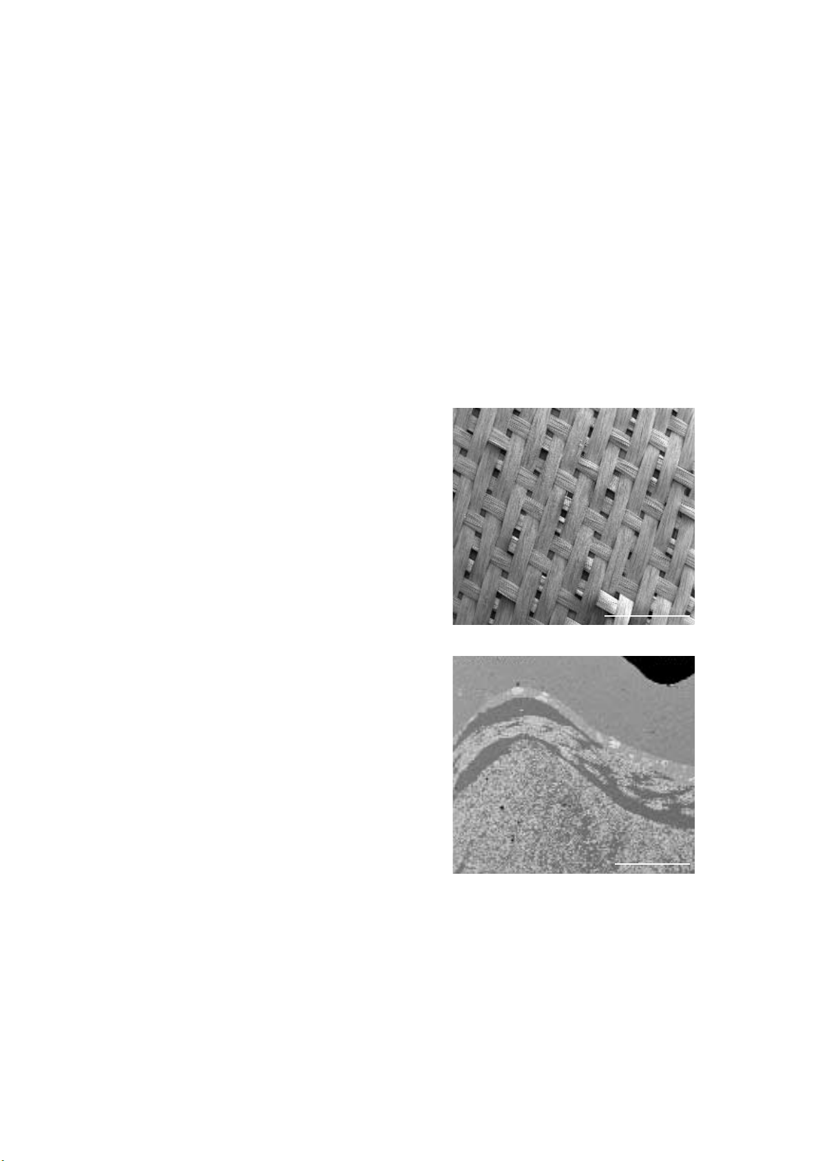
Vectris consists of several layers of fibre wafers and
uniaxially oriented fibre bundles embedded in an
organic polymer matrix. This matrix assures a
strong bond and homogeneously distributes the
masticatory forces exerted on the veneering
material throughout the framework.
1 mm
2 mm
We would like to thank Paolo Miceli from Italy for his
valuable cooperation in developing the technique
presented in these Instructions.
Page 7
7
PRODUCT INFORMATION
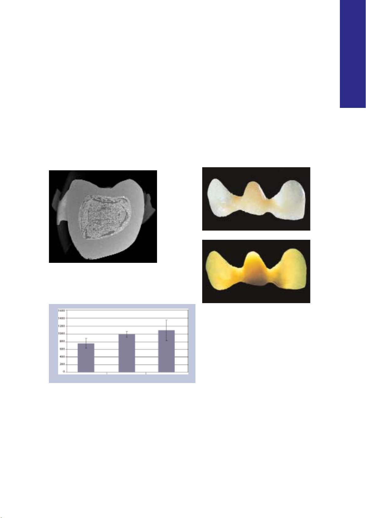
Fracture resistance (N)
Vectris framework fabricated
using the previous technique
Vectris framework fabricated
using the Transil technique
With Academy Gold XH
Physical properties
Vectris frameworks are characterized by an intimate stress-free fit and beneficial physical properties
thanks to a special manufacturing process that
combines the use of vacuum, pressure and light.
The frameworks are automatically formed and
polymerized in the VS1 framework former.
Furthermore, a newly developed working
technique – based on the Transil matrix material –
facilitates the fabrication of cusp-supporting frameworks. The flexural strength of these frameworks is superior to that of previous FRC frameworks.
Aesthetic properties
The translucent, tooth-coloured fibre wafers permit the fabrication of highly aesthetic frameworks.
Light can pass through the restoration without
being blocked by opaque areas of the substructure. The advantage of the FRC framework is also
apparent at the transition from the pink tissue
colour to the white tooth colour. The grey margins typically associated with metal restorations
are not present in Vectris-based reconstructions.
The cervical area exhibits a lifelike aesthetic
appearance.
Source: R&D, Ivoclar Vivadent AG, Schaan, 2003
Flexural strength of 3-unit posterior bridges using different
framework materials and designs. All frameworks are
veneered with SR Adoro.
Page 8
8
PRODUCT SYSTEM
Compatibility with SR Adoro
®
The metal-free Vectris frameworks can be veneered with
SR Adoro. SR Adoro is a microfilled, light/heat-curing
veneering composite for fixed
metal-supported and metalfree dental reconstructions.
SR Adoro offers several
advantages over glass-filled and hybrid composite
materials as regards wear, polishability, handling,
plaque resistance and surface finish. Furthermore,
the formulation of SR Adoro assures a smooth,
non-sticky consistency and endows the material
with excellent modelling properties. SR Adoro
demonstrates a high degree of translucency as the
light refraction index of the matrix and microfiller
are coordinated with each other. In addition,
the foundation material of SR Adoro exhibits
opalescent characteristics, which are equal to
those of the natural tooth in every respect. These
characteristics facilitate the fabrication of restorations that exhibit vibrant aesthetic properties. The
SR Adoro Liner, which is adjusted to the Vectris
framework material, establishes a strong bond
with the conditioned Vectris fibres.
Compatibility with SR Ivocron
®
SR Ivocron, a clinically proven,
high-quality PMMA veneering
material, is suitable for the
veneering of metal-free long-term
temporaries. By choosing the
appropriate monomer, SR Ivocron
can be processed in a cold-curing,
heat-curing or pressure-heat
curing technique. Consequently,
the processing technique can be
matched to the indication in
question as well as to the
technician's preferred working technique.
SR Ivocron is available in Chromascop shades. The
SR Ivocron system also includes specially coloured
cervical materials and is therefore compatible with
the SR Vivodent PE shade guide.
Compatibility with Ivoclar Vivadent
apparatus
Vectris VS1 is a high
performance, fully automated framework former
that has been especially
designed for the fabrication
of metal-free crown and
bridge frameworks. In the
VS1, the frameworks are
formed under pressure and then
polymerized with light using a single program.
Compatibility with Ivoclar Vivadent
cementation systems
Select one of the recommended cementation systems from the Ivoclar Vivadent
range. An array of suitable composite
resins are available for the adhesive
cementation of metal-free
restorations.
Adhesive cementation:
–Variolink II (CEM Kit Professional Set
or
CEM Kit Esthetic Cementation
System)
– Multilink
Zirconium oxide temporary cements are suited for
the cementation of long-term temporaries that
are intended to remain in the oral cavity for a
maximum duration of 12 months.
Page 9

9
PRODUCT INFORMATION
Indication
Adhesive cementation
– frameworks for anterior and posterior crowns
– frameworks for 3-unit anterior and posterior bridges in
conjunction with Transil
– frameworks for 3-unit inlay-retained bridges in conjunction with
Transil
Temporary cementation
Frameworks for long-term temporaries intended for a maximum
duration of wear of 12 months.
Contraindication
– fabrication of bridge frameworks without using Transil
– fabrication of posterior Vectris frameworks without cusp support,
if Transil is not used
–Vectris frameworks for bridges consisting of 4 or more units
–Vectris frameworks for inlay-retained bridges consisting of 4 or
more units
– cantilever extension bridges
– more than 4 fixed, permanent Vectris units per quadrant
–rehabilitation of quadrants with Vectris frameworks without
sufficient support by the remaining tooth structure
– conventional cementation of fixed Vectris restorations
– metal-free temporary restorations intended for a period of wear
longer than 12 months
– patients with occlusal dysfunctions or parafunctions, such as
bruxism, etc
– patients who practise insufficient oral hygiene
– inability to meet the manufacturer’s preparation guidelines and
recommended minimum layer thicknesses
– veneering of permanent Vectris-based restorations using
composites that are not indicated for Vectris
– all uses not explicitly stated as indications by the manufacturer
APPLICATIONS
Page 10

10
QUESTIONS
&
ANSWERS
What material should be used to prepare an
impression that can be poured several times?
A silicone, polyether or similar material should be used for
impression taking as these materials provide an optimum
reproduction of detail. Additionally, the impressions taken
with these materials can be poured several times.
Hydrocolloid and alginate materials are unsuitable and
cannot be poured more than once.
What if the impression needs to be poured only
once or if it has been damaged during the first
pouring?
In this case, a duplicating impression (Double Take) is
prepared with the help of the master model or a multi-
section model. Then, the impression is poured with type IV
stone.
Can the model be cut up into detachable
segments before preparing the duplicating
impression?
Ideally, the model is divided up into detachable segments
after the duplicating impression has been prepared. Block
out the cut lines with wax, if you have divided up the model
first.
MODEL PREPARATION
Can you wear latex gloves to process the matrix
material?
Latex gloves inhibit the curing of Transil. Therefore, Transil
should not come into direct or indirect contact with latex
gloves. For the processing of Transil, use vinyl gloves.
Does Transil need to be used each and every
time?
It is advisable to use Transil each time, as this material clearly
improves the adaptation of the Vectris fibres to the model,
provides a homogenous layer thickness and facilitates the
working procedure. It is imperative to use Transil for the
fabrication of bridges and inlay-retained bridges. The only
cases that do not require the use of Transil are dies of
posterior crowns with a flat occlusal preparation.
Can Transil be applied intraorally?
Transil must not be applied intraorally.
What characteristics should the exterior surface
of the Transil matrix exhibit?
The exterior surface should be as smooth as possible so that
it does not hinder the passage of light. Use the
accompanying Vectris foil to smooth the exterior surface
(prior to polymerization) or use a scalpel (after polymeriza-
tion). Light becomes scattered on rough, uneven surfaces
and, consequently, fails to penetrate the matrix effectively.
How thick should the Transil matrix be?
The matrix should be 3 to 6 mm thick. If it is thinner than
that, it may become deformed. If the matrix is thicker, the
Vectris material may not polymerize and cure properly.
Is it necessary to apply a Vectris foil if Transil is
used?
It is imperative to apply a Vectris foil only if you do not use
Transil. If you use Transil, you may employ the foil to smooth
the exterior surface of the silicone matrix while it is still soft.
How long is the working time of Transil?
The working time is approximately 1 minute.
SILICONE MATRIX
What is the minimum thickness for Vectris
frameworks?
Single crowns and bridge abutments must exhibit a mini-
mum framework thickness of at least 0.3. to 0.4 mm. The
surfaces should not be ground after the vacuum-forming
process has been completed.
What are the dimensions of the connector area
in bridges and inlay-retained bridges?
The connector area between the bridge abutment and
pontic should measure at least 3 x 3 mm in bridges and
inlay-retained bridges.
What are the appropriate dimensions for the
pontic/abutment contact area (occlusal and
palatal/lingual) when the pontic is placed?
The pontic/abutment contact area should measure at least
3 x 3 mm and should be at least 0.3 mm thick. It is
advisable to shape the pontic/abutment contact area in such
a way that it supports the cusps. The pontic should reach at
least 4 mm into the tooth for inlay-retained bridges.
What are the minimum dimensions of the inlay
box for inlay-retained bridges?
The proximal aspect of the box should be no less than
3.5 mm and the occlusal depth no less than 2.5 mm.
Observe the preparation guidelines.
FRAMEWORK DESIGN
Page 11

11
PRODUCT INFORMATION
What do I need to watch out for while carrying
out the sandblasting (conditioning) process?
Use Al2O3of a grit size of 80 to 100 microns (type 100) at a
pressure of maximum 1 bar (14.5 psi).
How long is the reaction time of the wetting
liquid?
Allow the liquid to react for 1 minute.
CONDITIONING
Can frameworks made of Vectris be veneered
with composites that are not explicitly recommended by the manufacturer?
Fixed, adhesively cemented restorations made of Vectris
must not be veneered with any other materials than those
recommended by the manufacturer. Temporarily cemented
long-term provisional restorations, which are intended to
remain in the oral cavity for no longer than 12 months, may
be veneered with other composites.
VENEERING
What equipment is needed to process Vectris?
A Vectris VS1 framework former is required to process
Vectris.
Can you cut slits into the Vectris Frame?
As Vectris Frame adapts very closely to the die because of the
Transil matrix, it is not necessary to cut slits. In fact, cutting
slits should be avoided, as the fibres would be severed in the
process. This weakens the strength of the restoration.
What happens if the stipulated curing depths
are not observed?
If the stipulated curing depths are not observed, the material
may not be able to polymerize completely. Clinical failure
may ensue.
Is it necessary to sandblast and condition the
pontic before Vectris Frame is applied?
After the vacuum-forming process, any Vectris matrix
material that has been squeezed downwards is carefully
removed with an appropriate instrument. Then, the Vectris
frame is directly applied on the inhibition layer of the pontic
(avoid contamination). Next, the Transil matrix is placed on
the die and the vacuum-forming process in the VS1 is
started. The inhibition layer provides a bond to the Vectris
Frame.
Do you ever sandblast and condition the pontic?
Only sandblast and condition the pontic if you have modified
the pontic surfaces by grinding and removed the inhibition
layer in the process.
V ACUUM
-
FORMING
Page 12

12
COMPOSITION
–Vectris Single
Dimethacrylate (48-50 wt%); glass fibres
(44–46 wt%); silicon dioxide (5–6 wt%).
Additional ingredients: stabilizers, catalysts and
pigments (<1 wt%)
–Vectris Pontic
Dimethacrylate (30–32 wt%); glass fibres
(64–66 wt%); silicon dioxide (3–4 wt%).
Additional ingredients: stabilizers, catalysts and
pigments (<1 wt%)
–Vectris Frame
Dimethacrylate (44-46 wt%); glass fibres
(49–51 wt%); silicon dioxide (5–6 wt%).
Additional ingredients: stabilizers, catalysts and
pigments (<1 wt%)
–Vectris Glue
Dimethacrylate (38–40 wt%); barium glass filler
and silicon dioxide (59–61 wt%).
Additional ingredients: stabilizers, catalysts and
pigments (< 1 wt%)
–Vectris Wetting Liquid
Silane in a water/alcohol solution
– SR Model Separator
Polyglycol, polyethylene glycol in a water/alcohol
solution
–Transil
Vinyl polysiloxane, polymethylhydrogen siloxane,
organic platinum complex and silicone dioxide
Warning
Vectris has been developed solely for use in dentistry. Prevent
contact of the eyes and skin with uncured material (Vectris fibres).
If the material comes into contact with the skin, rinse with copious
amounts of water. Contact of the skin with uncured material may
cause slight irritation and sensitization to methacrylate. Use suction
equipment and a protective mask when grinding the material.
Finishing the Vectris frameworks creates glass fibre dust, which
may cause the skin to itch. Wearing suitable gloves is
recommended. Thoroughly clean the skin that has come into
contact with glass fibre dust. Many commercially available
protective gloves do not provide effective protection against the
sensitizing effect of methacrylates. Observe the danger signs and
notes on the primary packaging and labels of the individual
materials.
Interaction
Latex gloves have an adverse effect on the polymerization of
polyvinyl siloxanes. For this reason, Transil must not come into
direct or indirect contact with latex gloves. It is advisable to use
vinyl gloves or to thoroughly wash and rinse the hands prior to
using Transil.
General
Ignoring the stipulated contraindications or limitations on the use
of the material (Questions & Answers) may result in the clinical
failure of the restoration fabricated. Make sure to use original
Ivoclar Vivadent materials and equipment when fabricating
prosthetic reconstructions with Vectris.
Side effects
Side effects are not known to date. In rare cases, an allergic reaction may occur. Vectris must not be used if the patient is suspected
or known to be allergic to any of the material’s ingredients.
Storage
– Store unopened and opened packages of Vectris framework
material at 18–25 ºC (64–77 ºF).
– Store opened Vectris packages in a place that is protected from
light and use up the contents as soon as possible.
– Reseal Vectris Glue immediately after use (exposure to light may
result in premature polymerization).
– Store Transil at 12–28 ºC (54–82 ºF).
– Observe the notes on the storage and dates of expiration of the
individual packages.
– Do not use materials after the date of expiration.
– Keep out of the reach of children.
Note on the cleaning of Vectris restorations
Ultrasonic cleaning liquid is very aggressive. If used inappropriately,
the topmost layer of the composite surface may dissolve. Do not
use basic cleaning liquids that have a pH-value higher than 8.
Page 13

13
WORKING TIMES
PRODUCT INFORMATION
Vectris materials are sensitive to light. The working
time of the material depends on the layer thickness
and the prevailing light conditions. The times listed
below represent mean values at a light intensity of
3000 lux, which corresponds to the light encountered
in a well-lit working space. Be aware of the maximum
time limit when removing the Vectris framework
materials from the packaging.
Vectris Single 2 minutes and 30 seconds
Working time
Vectris Pontic 3 minutes
Vectris Frame 2 minutes and 30 seconds
Vectris Glue 2 minutes and 30 seconds
Page 14
14
DESCRIPTION OF ASSORTMENTS
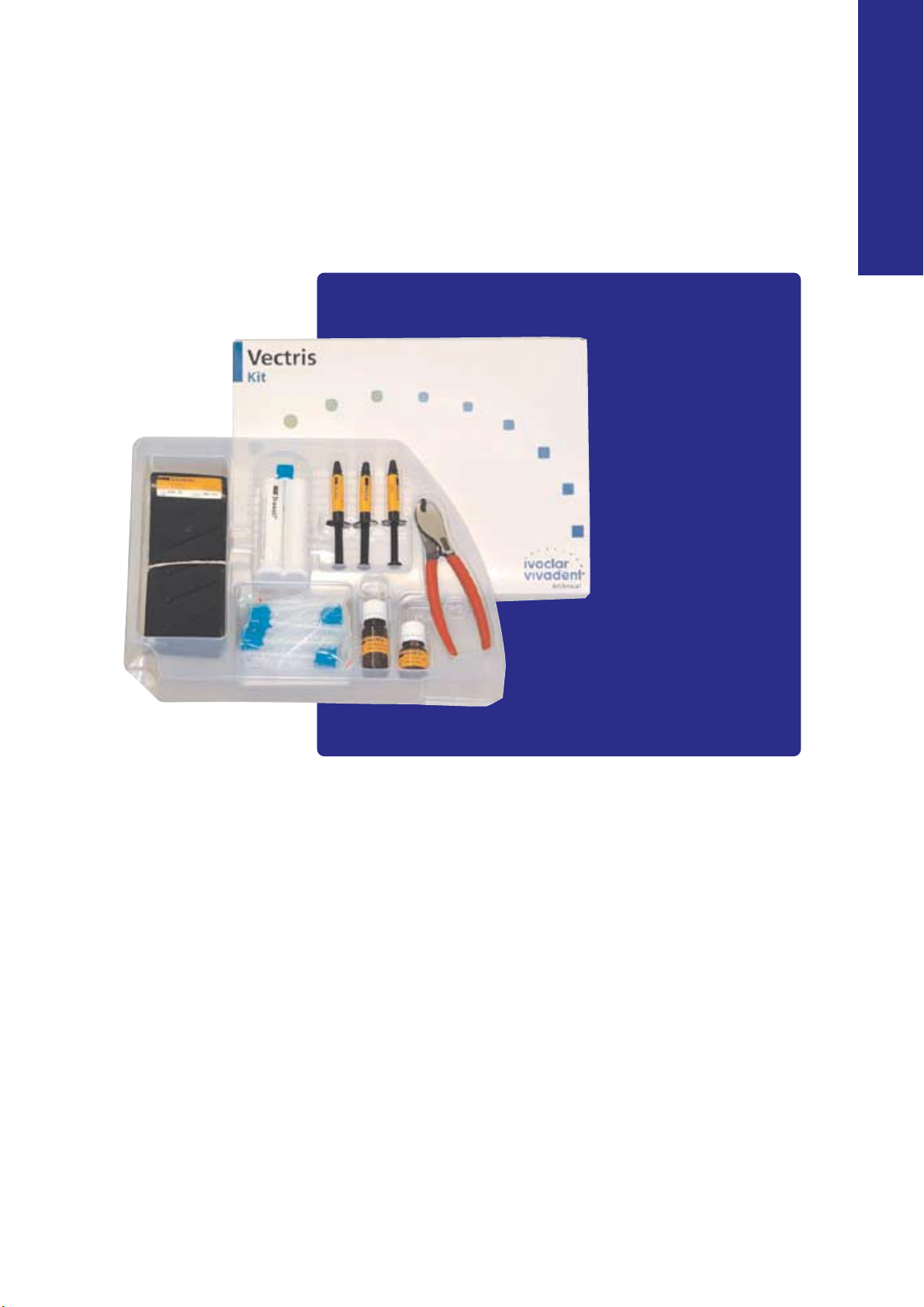
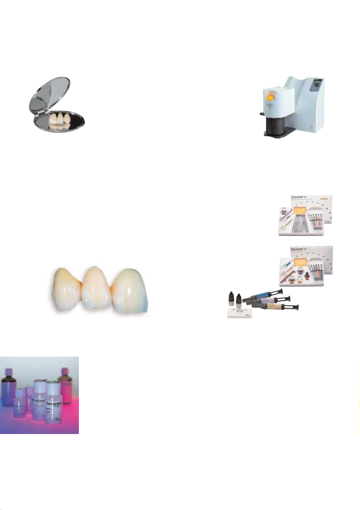
Vectris Kit
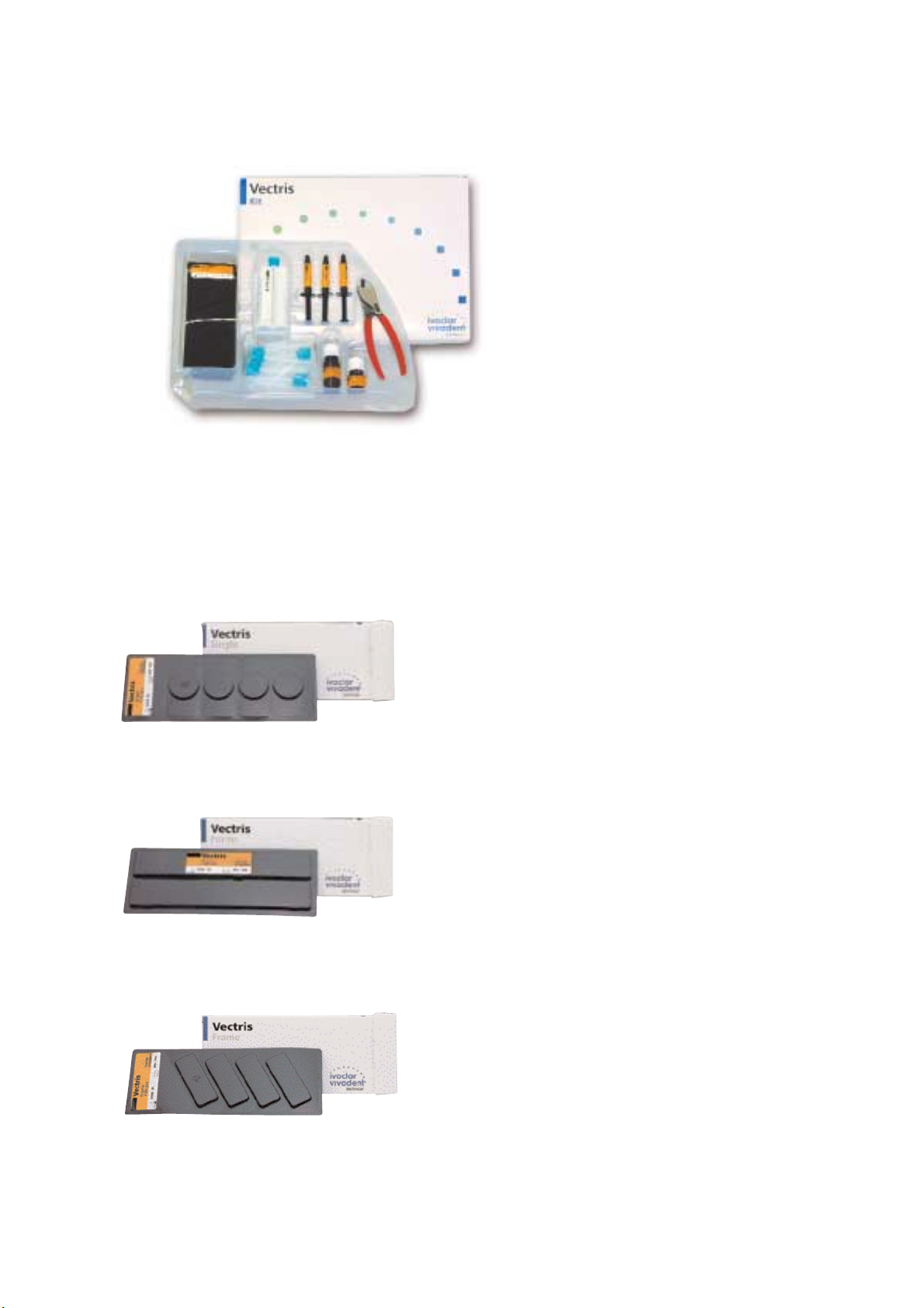
Vectris Single
Vectris Single is suitable for fabricating frameworks for anterior and
posterior crowns.
Vectris Pontic
Vectris Pontic is employed to create cusp-supporting pontics or to
reinforce the cusps in single crowns. Vectris Pontic is characterized
by high flexural strength. As the pontic is wrapped in foil, it can be
easily measured out and cut to size. These strips, when cut, are fitted
into the Transil matrix one by one.
Vectris Frame
Vectris Frame is wrapped around the cusp-supporting pontic and
bridge abutments. This technique results in a bridge framework with
having physical properties. The flexible structure of Vectris Frame
evenly distributes the masticatory forces on the bridge and increases
the torsional resistance.
Delivery form
Vectris Kit
– 4x4 Vectris Single
dimensions: diameter: 24 mm
– 2x2 Vectris Pontic
dimensions: length: 150 mm
– 4x4 Vectris Frame
dimensions: length: 40 mm; width: 25 mm
– 3x 2 ml Vectris Glue
– 1x 5 ml Vectris Wetting Liquid
– 1x 25 Vectris Foil
– 1x 10 ml Vectris Model Separator
–Vectris Pliers
– 2x 50 ml Transil Cartridge
– 12 Mixing Tips
Page 15
15
PRODUCT INFORMATION
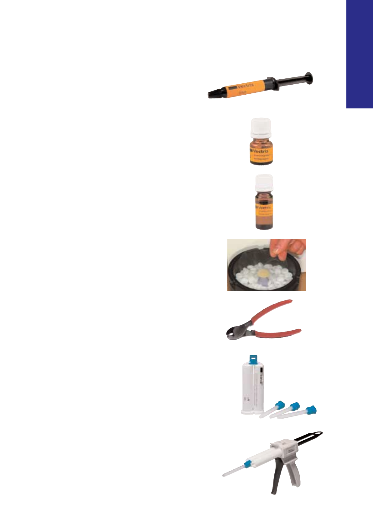
Vectris Glue
Vectris Glue holds the Vectris material in place in the Transil matrix
until the vacuum-forming process is carried out and serves as an
additional aid to adaptation.
Vectris Wetting Liquid
The wetting liquid is applied to condition the fully completed
surfaces of Vectris frameworks in order to achieve an effective bond
to the following Vectris material and the SR Adoro Liner.
Vectris Model Separator
The Vectris Model Separator is suitable for separating working dies
during the fabrication of metal-free restorations and adjoining stone
surfaces during composite veneering.
Vectris Foil
The foil reduces the formation of an inhibited layer during the lightcuring process and, consequently, enables the framework material to
cure completely. The foil is only used for applications without Transil.
Vectris Pliers
These pliers are used to cut Vectris Pontic to size.
Transil
Transil is utilized to manufacture reproducible, cusp-supporting
Vectris frameworks. This silicone enables users to design frameworks
according to the classic metal-ceramic technique. Transil offers easy
and fast handling properties. The disposable mixing tips are used to
mix the two components to a homogeneous mixture. Cuspsupporting, anatomically designed Vectris frameworks provide
increased strength and reduce the risk of delamination.
Dispenser
The dispenser is suitable for Ivoclar Vivadent materials that are mixed
in a 1:1 ratio (e.g. Gingitech, Virtual, etc).
Page 16

16
Page 17
17
WORKING PROCEDURE
Vectris
®
WORKING PROCEDURE
Page 18
18
PREPARATION GUIDELINES AND MINIMUM
REQUIREMENTS FOR VECTRIS FRAMEWORKS
As Vectris restorations are luted in place using an adhesive cementation method, a tooth-conserving
preparation technique can be used.
Anterior crowns and bridge abutments
Evenly reduce the anatomical shape and observe the stipulated minimum thickness. Prepare a 360°
shoulder with rounded inner edges or a deep chamfer of at least 0.8 mm. For anterior crowns, the labial
and/or palatal/lingual surfaces should be reduced by at least 1.0 mm. Reduce the incisal crown third by at
least 1.5 mm. Prepare smooth, rounded transitions so that no internal line angles or edges are present.
0.8
0.8
≥1
≥1
1.5
Posterior crowns and bridge abutments
Evenly reduce the anatomical shape and observe the stipulated minimum thickness. Prepare a 360° shoulder
with rounded inner edges or a deep chamfer. For posterior crowns, reduce the labial and/or palatal/lingual
surfaces by at least 1.0 mm. Reduce the occlusal crown third of posterior teeth by at least 1.5 mm. Prepare
smooth, rounded transitions so that no internal line angles or edges are present.
1.5
1.5
1.5
≥1
≥1
0.8
0.8
Page 19

19
WORKING PROCEDURE
Inlay-retained bridges
Provide a preparation depth of at least 2.5 mm and an isthmus width of at least 2 mm in the fissure area.
The walls of the proximal box should be slightly flared. The bucco-lingual cavity width should be at least
3.5 mm in the proximal box. The proximocentral length should measure at least 4.0 mm, while the axial
depth should be at least 1.2 mm. A defect- and tooth-oriented preparation method may be used to prepare
the proximal shoulder. Ideally, a shoulder of at least 1.5 mm should be prepared. Round all internal angles to
allow for an optimum fit. Do not locate preparation margins on surfaces involved in masticatory functions.
Eliminate proximal contacts. Do not prepare slice-cut or feather edge margins.
Please refer to the SR Adoro Instructions for Use and the SR Adoro Clinical Guide for further information.
2.5
≥4
≥1.2
≥3.5
2.5
≥ 3.5
2.5
2
Page 20

20
Duplicate die/model ✔* ✔* ✔✔* ✔
Transil matrix ✔✔* ✔✔✔
Framework thickness at least at least at least at least at least
Vectris abutment 0.3–0.4 mm 0.3–0.4 mm 0.3–0.4 mm 0.3–0.4 mm 0.3–0.4 mm
Joint face of the connector ––at least at least at least
3 x 3 mm 3 x 3 mm 3 x 3 mm
Thickness of pontic/abutment ––at least at least at least
contact layer 0.3 mm 0.3 mm 0.3 mm
Length of the pontic/abutment ––at least at least at least
contact layer 3 mm 3 mm 3 mm
Long Pontic ribbon ––1 x1 x1 x
Medium-sized Pontic ribbon ––1 x1 x1 x
Short Pontic ribbon – ✔* 2–3 x 3–5 x 3–5 x
Grit size of Al2O3jet medium 80–100 µm 80–100 µm 80–100 µm 80–100 µm 80–100 µm
Pressure 1 bar (14.5 psi) 1 bar (14.5 psi) 1 bar (14.5 psi) 1 bar (14.5 psi) 1 bar (14.5 psi)
Cleaning with air or steam
Minimum reaction time 1 min. 1 min. 1 min. 1 min. 1 min.
of the wetting liquid
Anterior
crowns
Posterior
crowns
Anterior
bridges
Posterior
bridges
Inlay-retained
bridges
It is essential to observe the following points when designing Vectris frameworks:
1. Designing the silicone matrix
2. Designing the framework for single crowns
2.1 Anterior crowns
2.2 Posterior crowns with a flat occlusal preparation
2.3 Posterior crowns with a deep occlusal preparation
2.4 Posterior crowns without supporting cusps
3. Designing the pontic
3.1 Pontic
3.2 Joint face of the connector
3.3 Pontic/abutment contact layer
4. Trimming the margins of Vectris frameworks
5. Placing Vectris Pontic into the Transil matrix
The indicated numbers of Pontic strips are reference values and may differ depending
on the situation in question.
FRAMEWORK DESIGN
✔ indicated
✔* advisable
contraindicated
Page 21

21
WORKING PROCEDURE
1. Designing the silicone matrix
If the silicone matrix (laboratory silicone and Transil) has been shaped correctly, the work required to finish the Vectris
framework is reduced to a minimum.
Single crowns without Transil
For single crowns, always adapt the laboratory silicone (Sil-Tech) to the die in a conical shape and adapt precisely to the
preparation margin. This method ensures that the Vectris Single effectively adapts to the cervical area during the vacuumforming process. If the silicone forms a shoulder, Vectris Single cannot adapt properly to the margin. The result is thick
cervical margins. Such margins would need to be removed mechanically after the vacuum-forming process.
correct
incorrect
Single crowns with Transil
It is advisable to first apply a layer of laboratory silicone (Sil-Tech), form it into a conical shape and then cut a shoulder
about 1 cm down from the preparation margin in order to support the following Transil matrix. If necessary, retention
grooves may be cut into the silicone (Sil-Tech). Next, separate the laboratory silicone with a thin layer of Vaseline and apply
Transil. The Transil matrix should be 3 to 6 mm thick to exhibit adequate stability.
correct
incorrect
Page 22

22
2. Designing the framework for single crowns
Whether Transil should be utilized to fabricate the framework for a single crown depends on the preparation. In principle,
it is advisable to create a Transil matrix for every framework to facilitate the adaptation of the Vectris fibres to the die.
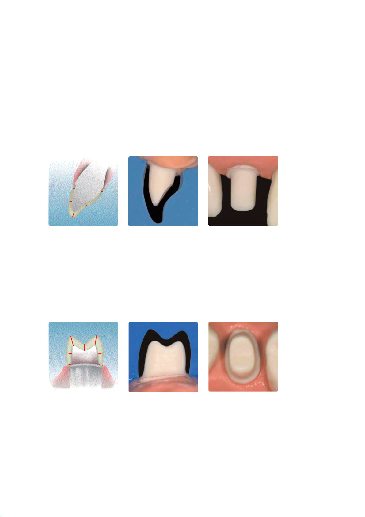
2.1 Anterior crowns
When the framework for an anterior crown is fabricated, it is advisable to use the Transil technique to facilitate the adaptation of Vectris Single to the die. The Transil technique helps to attain a consistent layer thickness on both the tooth
surface and incisal edge of steep, sharply pointed anterior preparations in particular. Upon completion of the vacuumforming process, merely trim the margins of the Transil matrix. Do not grind the surfaces.
correct
incorrect
2.2 Posterior crowns with a flat occlusal preparation
If a flat occlusal preparation is present, it is not necessary to use Transil. With flat preparations, Vectris Single adequately
adapts to the preparation margins during the vacuum-forming process and a consistent layer forms on the occlusal
surface even without the use of Transil. Adapt the laboratory silicone as described above. After separating it with Vectris
Model Separator, apply Vectris Glue and Vectris Single and then cover it with a Vectris foil. Start the vacuum-forming
process in the Vectris VS1. Upon completion of the program, trim and taper the margins. Do not grind the surfaces.
correct
incorrect
Page 23

23
2.3 Posterior crowns with a deep occlusal preparation
It is imperative to use Transil if a deep occlusal preparation is present. The Transil technique ensures that the material
consistently adapts to all surfaces of the die, including the occlusion. If Transil is not employed, the occlusal surface would
become completely filled with Vectris matrix material and, consequently, would need to be reduced another time by
grinding this material off. Upon completion of the vacuum-forming process, merely trim the margins of the Transil matrix.
Do not grind the surfaces.
correct
incorrect
2.4 Posterior crowns without supporting cusps
It is imperative to use Transil if only limited remaining tooth structure is available (e.g. no cusp support). The missing tooth
structure must be compensated by the framework and not by the veneering material. Contour the missing portions (e.g.
cusp support) in wax in order to be able to apply the veneering material in a consistent layer thickness of approx. 1.5 mm
at a later stage. Next, create a Transil matrix, fill up the missing portions with Vectris Pontic and vacuum-form in the Vectris
unit. Then, apply Vectris Single and again vacuum-form in the Vectris unit to complete the framework. This method allows
for the fabrication of shape- and cusp-supporting frameworks. Furthermore, the consistent thickness of the veneering
material facilitates the creation of a harmonious shade effect and provides a maximum level of beauty and function.
correct
incorrect
WORKING PROCEDURE
Vectris Pontic
Page 24

3. Designing the pontic
The pontic, connector and pontic/abutment contact surface are first contoured in wax and/or resin (Light Tray) and then a
silicone matrix is fabricated.
3.1 Pontic
Pontics are designed taking aesthetic and functional aspects as well as oral hygiene into consideration. The pontic must
not be larger than 10 mm in width and height to ensure that the material cures to an adequate depth. As a rule, the
pontic should be designed in such a way that it supports the cusps to ensure that the masticatory forces are evenly
distributed throughout the framework and to provide adequate support of the veneering material. Furthermore, cuspsupporting pontics reduce the risk of delamination.
correct
3.2 Joint face of the connector
The design of the interdental connector between the pontic and the bridge abutment has a considerable effect on the stability and long-term clinical success of the restoration after it has been adhesively cemented in place. The dimension of the
interdental connector should measure at least 3 x 3 mm, i.e. the surface of the connector should be at least 9 mm2.
incorrect
24
≥ 3 mm
≥ 3 mm
Page 25

25
WORKING PROCEDURE
3.3 Pontic/abutment contact layer
The pontic/abutment contact layer has a significant effect on the stability and torsional resistance of the bridgework. The
contact layer is designed according to the space available. For full coverage bridges, the contact layer should measure at
least 3 x 3 mm and be 0.3 mm thick. If enough space is available, it is advisable to contour a cusp-supporting pontic/
abutment contact layer in wax in order to attain a consistent layer thickness of approx. 1.5 mm in the veneering material.
For inlay-retained bridges, the pontic/abutment contact layer should be at least 0.3 mm thick and 4 mm long.
Limited space available Ideal space available
Pontic/abutment contact
area on anterior teeth
Pontic/abutment contact
area on molars
Pontic/abutment contact
area on premolars
≥ 0.3 mm
≥ 0.3 mm
≥ 0.3 mm
Page 26

26
4. Trimming the margins of Vectris frameworks
After completing the vacuum-forming process, trim the margins of the Vectris restoration by 0.5 mm to the inner edge of
the chamfer or shoulder preparation. Make sure that the framework continues to be supported by the die after trimming
the margins.
correct
incorrect
Bridge design if limited
space is available
Bridge design if ideal
space is available
≥ 3 mm
≥ 3 mm
Page 27

27
5. Placing Vectris Pontic into the Transil matrix
The Transil matrix is filled with Vectris Pontic material according to the schematic below. Basically the schematic applies to
all pontics. It may be necessary to trim the length of the individual Vectris Pontic strips to match the dimensions of the
pontic in question. Vectris Pontic strips in three different lengths are placed to fill the pontic:
short Vectris Pontic strips are used for creating cusp tips, occlusal surfaces and the base surface of the pontics
medium-size Vectris Pontic strips are used for the portion between bridge abutments
long Vectris Pontic ropes are used for connecting the bridge abutments and establishing the pontic/abutment contact
surfaces
The long Vectris Pontic strip is the most important part as it endows the pontic and the resultant bridgework with its
actual strength. Always employ a long Vectris Pontic strip to connect the two bridge abutments. Use a medium-size Vectris
Pontic strip to establish a connector area of 3 x 3 mm between the bridge abutments. It is advisable to place the Vectris
Pontic strips in the following order:
1. Slightly moisten the cavity of the Transil matrix with Vectris Glue
2. Insert short Vectris Pontic strips to create a cusp-supporting structure (if necessary, place short strips on the
bridge abutments as well)
3. Place a long Vectris Pontic strip to connect the bridge abutments
4. Insert a medium-size Vectris Pontic strip to establish a connector area of 3 x 3 mm between the bridge abutments
5. Place short Pontic strips and contour the base surface of the pontic
WORKING PROCEDURE
short
short
short
short
medium-size
long
short
medium-size
long
Page 28

28
CEMENTATION
Adhesive cementation of metal-free restorations results in a tight bond between the restoration and prepared tooth. Such
a bond enhances the fracture resistance of the restoration. The translucent shade of the adhesive and the virtually invisible
margins promote the aesthetic appearance of the restoration. The following materials are suitable for the adhesive
cementation method:
–Variolink II (CEM Kit Professional Set or CEM Kit Esthetic Cementation System)
– Multilink
Temporary cementation
Zinc oxide containing temporary cements are suitable for metal-free long-term temporaries that are intended to remain
in the oral cavity for a maximum duration of 12 months.
Preparing the restoration for cementation
The contact surfaces of the restoration are roughened with type 100 Al203at 1 bar (14.5 psi) pressure in the laboratory
to promote chemical bonding with the luting composite. Following the try-in and subsequent cleaning, the contact
surfaces are again roughened using a 25 µm finishing diamond. This step is carried out immediately before adhesive
cementation. Finally the surfaces are silanized (e.g. with Monobond S) to enable a chemical bond.
Please refer to the SR Adoro Clinical Guide for further information on appropriate
cementation techniques.
Page 29

29
Vectris
®
SINGLE CROWNS
SINGLE CROWNS
Page 30

30
VECTRIS SINGLE CROWNS
Tip:
It is advisable to pour a duplicate die to carry out the vacuum-forming process, as the sharply pointed incisal edges may
cause delamination of the stone die.
Starting situation
Fabricate a master model or a model with detachable segments on the basis of the impression in the usual manner. Expose
and mark the preparation margin. It is advisable to apply a sealer to harden the surface and to protect the stone die. The
application of the sealer must not cause any changes in the dimension of the stone die. Subsequently, a spacer can be
applied, depending on the customary working method.
Working method for different preparations
The following instructions describe the procedure for a flat occlusal preparation (Version A) and a deep occlusal preparation
(Version B).
Fabricate a model with detachable segments. Mark the preparation margins...
…and apply a sealer to harden the surface. Completed working die.
Version A
Flat occlusal preparation
Version B
Deep occlusal preparation
Page 31

31
Fabricating the silicone matrix
Silicone matrix made of laboratory silicone (Sil-Tech)
Remove the individual dies from the model. Carefully cover the die with laboratory silicone and adapt the material
exactly to the preparation margin. Prepare a shoulder approx. 1 cm down from the preparation margin to facilitate the
repositioning of the Transil matrix.
Tip:
Smooth out the exterior surface with a Vectris foil while the material is still soft. Mark the laboratory silicone and Transil
with a waterproof pen to obtain an exact repositioning of the matrices.
SINGLE CROWNS
Fit the laboratory silicone to the die in a conical shape. Fit the laboratory silicone to the die in a conical shape and prepare a shoulder approx. 1 cm
down from the preparation margin.
Version A
Flat occlusal preparation
Version B
Deep occlusal preparation
Silicone matrix made of Transil
If a deep occlusal preparation (Version B) is present, prepare a second matrix using Transil (transparent silicone). Separate
the laboratory silicone with a thin coat of Vaseline to prevent the two silicone materials from sticking to each other. Insert
the Transil cartridge into the dispenser, mount a new mixing tip and apply Transil to the die in a single step. Transil should
be applied in a layer thickness of approx. 3 to 6 mm to obtain sufficient stability. The setting reaction may be accelerated
by using a hot air dryer. After the material has set, smooth out the exterior surface to enhance the passage of light.
Subsequently, remove the Transil matrix from the die.
Apply a thin coat of Vaseline to the laboratory silicone and then apply Transil. Smooth out the exterior surface of the Transil matrix with a scalpel.
Page 32

32
Sealing the dies
Vectris Model Separator is applied in two coats. Apply the first layer slightly more generously than the second one and
make sure to fully cover all areas of the die. Watch out for sharp edges in particular. Allow the first layer to react for
3 minutes. Subsequently, apply the second layer of Vectris Model Separator in a thin coating, invert the die and allow to
dry for 3 minutes.
Apply a generous coating of Vectris Model Separator and allow it to dry for 3 minutes.
Apply the second layer of Vectris Model Separator in a thin coating,invert the die and allow it
to dry for 3 minutes.
Version A
Flat occlusal preparation
Version B
Deep occlusal preparation
Preparing the die for the vacuum-forming process
Before removing the Vectris Single from the packaging, adjust the height of the model carrier in the vacuum former so that
the distance between the model and the upper rim of the container is 2 to max. 3 cm. If necessary, further adjust the
height by means of the spacer rings. Finally, check the position of the membrane.
Check the height of the model on the model carrier and, if necessary, adjust by means of the spacer rings.
Version A
Flat occlusal preparation
Version B
Deep occlusal preparation
2– max. 3 cm
2– max. 3 cm
Page 33

33
SINGLE CROWNS
Vacuum-forming the Vectris Single – Version A
Application of Vectris in the Vectris VS1 framework former: Position the die in the framework former, apply a small
amount of Vectris Glue to the die to keep Vectris Single in place while it is on the die. Remove the Vectris Single from the
light-protected package, place Vectris Single on the die using tweezers and lightly press it into place. Next, cover the Vectris
Single with a Vectris foil to reduce the inhibited layer. Then, close the Vectris VS1 unit and start Program 1 to commence
the vacuum-forming and polymerization process. The program takes 10 minutes to complete.
Position the die in the Vectris VS1 unit; apply a small amount of Vectris Glue to the die.
Remove the Vectris Single from the light-protected package; place it on the die with tweezers and lightly press it into place.
Cover with Vectris foil; start Program 1 for the vacuum-forming and polymerization process.
Page 34

34
Vacuum-forming the Vectris Single – Version B
Application of Vectris outside the Vectris VS1 framework former: Remove the Vectris Single from the light-protected
package and place it on the die with tweezers. Place the Transil matrix on the Vectris Single in the correct position, push it
downwards and mount the die on the model carrier of the Vectris VS1.
Remove the Vectris Single from the light-protected package and place it on the sealed die.
Place the Transil matrix over the Vectris Single and press it downwards.
Position the die with the Transil matrix in the VS1. Start the vacuum-forming and
polymerization process. The program takes 10 minutes to complete.
Page 35

35
SINGLE CROWNS
Removing the framework from the die
After completion of the vacuum-forming process, first remove the Vectris foil or Transil matrix from the framework and
then carefully remove the framework from the die while it is still warm. If the restoration is removed at a later stage, it is
advisable to warm up the stone die by means of water vapor. The framework exhibits an even layer thickness after it has
been removed from the die.
Upon completion of the vacuum-forming process, remove the Vectris foil or
Transil matrix from the framework.
Excellent adaptation of the occlusal surface
Version A
Flat occlusal preparation
Version B
Deep occlusal preparation
Page 36

36
Finishing
Remove large areas of excess material with a separating disk and then trim the remaining excess material with cross-cut
tungsten carbide burs. It is advisable to use a slow rotational speed and light pressure. The thickness of the walls, which
is 0.3 to 0.4 mm after the vacuum-forming process, must not be reduced by grinding. Trim the margins by
approx. 0.5 mm to the inner edge of the chamfer or shoulder preparation. Make sure that the framework continues to
be supported by the die after having trimmed the margins.
Remove large pieces of excess material with a separating disk.
The result
Trim the margins by approx. 0.5 mm using a tungsten carbide bur.
The SR Adoro Instructions for Use provide detailed information on the conditioning and veneering
of Vectris frameworks.
Page 37

37
Vectris
®
3-
UNIT ANTERIOR BRIDGES
3-
UNIT ANTERIOR BRIDGES
Page 38

38
3-
UNIT ANTERIOR BRIDGES
Starting situation
Fabricate a master model or a model with detachable segments on the basis of the impression in the usual manner. Expose
and mark the preparation margin. It is advisable to apply a sealer to harden the surface and to protect the stone die from
abrasion. The application of the sealer must not cause any changes in the dimension of the stone die. Subsequently, a
spacer can be applied, if this is the customary method of working.
Fabricate a model with detachable segments and apply a sealer.
Fabricating the duplicate model for the vacuum-forming process
Bridge constructions for the anterior region in particular often involve sharply pointed incisal edges. As these edges are
prone to delamination during the vacuum-forming process, a duplicate model has to be prepared. The master model is
utilized to contour the pontic (including the pontic/abutment contact layer), to check the fit of the restoration and to
veneer the framework. Pour the original impression a second time and create a small duplicate model for the vacuumforming process. Make sure to eliminate undercut areas to facilitate the subsequent application of the Transil matrix.
Fabricate a duplicate model from the original impression and eliminate undercut areas.
–A silicone, polyether or similar material should be used for impression taking as these materials provide an
optimum reproduction of detail. Additionally, the impressions taken with these materials can be poured
several times.
– Hydrocolloid and alginate materials are unsuitable and, besides, cannot be poured more than once.
The following pages provide instructions on how to fabricate the framework of a 3-unit Vectris bridge (full crown bridge)
for the anterior region. For posterior bridges, the Vectris material is placed in the Transil matrix in a similar technique as for
3-unit inlay-retained bridges. Further information that is relevant to the fabrication of posterior bridges can be found on
page 20 onwards.
Page 39

39
3-
UNIT ANTERIOR BRIDGES
Contouring the pontic
First, seal the dies with a wax/stone or resin/stone separator. Form the pontic on the master model in a shape- and cuspsupporting manner similar to the metal-ceramic technique, using wax or composite (Light Tray). This step helps to obtain a
homogeneous layer thickness in the following veneering material. The palatal or lingual abutment/pontic contact layers
should exhibit the following dimensions:
– surface: at least 3 x 3 mm
– thickness: at least 0.3 mm
– joint face of the connector: at least 3 x 3 mm
It is advisable to contour the pontic insert in a shape-and cusp-supporting design, depending on the space available. Check
the pattern in the articulator and adjust as necessary. If a full wax-up has been prepared, the wax rim may be used for
checking purposes.
Contour the pontic on the master model.
Check as to whether the minimum requirements are met by means of the wax rim.
Conduct a final check in the articulator.
Tip:
The pontic can be contoured using a tray material (Light Tray) and adjusted by grinding after completion of the
polymerization process.
≥ 3 mm
≥ 3 mm
Page 40

40
Transferring the pontic to the duplicate model
Transfer the fully contoured pontic to the duplicate model and use a small amount of wax to hold it in place. Block out the
basal surface of the pontic using laboratory silicone (Sil-Tech) in order to ensure that the following Transil matrix can be
removed easily. It is important to block out this area since it will determine the way in which the Vectris Frame wraps
around the Vectris Pontic. The portion of the basal surface that is in contact with the laboratory silicone should not be too
wide. The following instructions should be observed when transferring the pontic to the duplicate model:
1. Reduce the basal surface of the duplicate model and prepare retention.
2. Transfer the pontic to the duplicate model and hold it in place with a small amount of wax.
3. Block out the reduced basal surface using laboratory silicone (Sil-Tech).
4. Reduce the blocked out area by means of a scalpel or bur.
Reduce the basal surface of the duplicate model and transfer the pontic to the model.
Block out the basal reduction with laboratory silicone and then reduce the blocked out area.
Pontic on the duplicate model after completion of the transfer process.
Page 41

41
3-
UNIT ANTERIOR BRIDGES
Fabricating the Transil matrix
Separate the laboratory silicone with a thin coat of Vaseline to prevent the two silicone materials from sticking to each
other. Insert the Transil cartridge into the dispenser, mount a fresh mixing tip and apply Transil to the die and pontic in a
single step. Transil should be applied in a layer thickness of approx. 3 to 6 mm to obtain sufficient stability. The setting
reaction may be accelerated by using a hot air dryer. After the material has set, smooth out the exterior surface and form it
into a conical shape to enhance the passage of light. Subsequently, remove the Transil matrix from the die.
Apply a thin coating of Vaseline to the laboratory silicone and then apply Transil.
Smooth out the exterior surface of the Transil matrix and form it into a conical shape.
Tip:
A Vectris foil may be used to smooth out the exterior surface while it is still soft.
Tip:
In order to facilitate the flowing off of Vectris matrix material, small spillways may be cut into the palatal and labial
portions of the laboratory silicone after the Transil matrix has been removed.
Page 42

42
Sealing the dies
After having removed the matrix and cleaned the duplicate model, apply two layers of Vectris Model Separator. Apply the
first layer slightly more generously than the second one and make sure to fully cover all areas of the die. Watch out for
sharp edges in particular. Allow the first layer to react for 3 minutes. Subsequently, apply the second layer of Vectris Model
Separator in a thin coating, invert the model and allow it to dry for another 3 minutes.
Preparing the dies for the vacuum-forming process
Before removing the Vectris Single from the packaging, adjust the height of the model carrier in the vacuum former so that
the distance between the die and the upper rim of the container is 2 to max. 3 cm. If necessary, the height may be further
adjusted with the help of the spacer rings. Finally, check the position of the membrane.
Placing Vectris Pontic into the Transil matrix and vacuum-forming the pontic
Slightly moisten the Transil matrix with Vectris Glue to facilitate the adaptation of the Vectris Pontic strips. Remove the
Vectris Pontic from the light-protected package, cut it to the desired length, remove it from the foil and place it into the
Transil matrix using tweezers. Observe the schematic below when filling in the individual Vectris strips. Place the Transil
matrix on the duplicate model in the correct position, push it into place and mount the model on the model carrier of the
Vectris VS1. Start Program 1 to commence the vacuum-forming and polymerization process. The program takes 10 minutes
to complete.
Apply a generous coat of Vectris Model Separator and allow to dry for approx. 3 minutes. Apply the second layer of Vectris Model Separator in a thin coating and allow to dry for
3 minutes upside down.
Schematic of the order in which the individual Vectris strips have to be placed. Moisten the Transil matrix with Vectris Glue.
Page 43

43
3-
UNIT ANTERIOR BRIDGES
First, place a short Vectris strip… …then insert a long Vectris strip for the pontic/abutment inserts…
…and complete with medium-sized and short strips; place the pontic on the duplicate model.
The vacuum forming and polymerization process takes 10 minutes with Program 1.
Page 44

44
Important:
If it is impossible to avoid modifications involving grinding, then sandblast the entire pontic surface with type
100 Al2O3at 1 bar (14.5 psi) pressure.After sandblasting, remove residue by tapping it off and not by cleaning the
surfaces with steam or an air gun. If necessary, a clean disposable brush may be used for this purpose. Apply
Vectris wetting liquid immediately after having removed the residue. Use a disposable brush to apply the liquid
and allow it to react for 60 seconds. Disperse excess material with oil-free compressed air and replace the pontic
on the duplicate model.
Vacuum-forming the Vectris Frame
Remove only the Transil matrix; leave the pontic on the duplicate model. Remove any Vectris matrix material that has been
squeezed downwards, using an appropriate instrument. If the pontic inadvertently comes off along with the Transil matrix,
carefully remove it from the matrix and reposition it on the duplicate model. Do not grind or contaminate the pontic.
Subsequently, remove the Vectris Frame from the light-protected package and place it on the Vectris Pontic. Do not cut
slits into the Vectris Frame. Place the Transil matrix over the duplicate model, push it into place and position the model
at the centre of the container in the framework former. Start Program 1 to commence the vacuum-forming and
polymerization process. The program takes 10 minutes to complete.
Place the Vectris Frame on the pontic, place the Transil matrix over the model and press it into place.
The vacuum-forming process results in optimum shape and adaptation of the Vectris Frame.
Page 45

45
3-
UNIT ANTERIOR BRIDGES
Removing the framework from the die
Upon completion of the vacuum forming process, remove
the Transil matrix and lift the framework from the die. If the
framework cannot be readily removed, warm up the framework and the duplicate model by means of a steam jet and
then try again. Remove excess material using a separating
disk while the framework is still on the model.
Subsequently, carefully remove the framework from the die.
…and carefully remove the framework from the die, using an appropriate instrument.
Remove excess material while the framework is still on the model…
Page 46

46
Finishing
Remove excess material in the marginal areas with cross-cut tungsten carbide burs. It is advisable to use a slow rotational
speed and light pressure. The thickness of the walls, which is 0.3 to 0.4 mm after the vacuum forming process,
must not be reduced by grinding. Trim the marginal areas by approx. 0.5 mm to the inner edge of the chamfer or
shoulder preparation. Make sure that the framework continues to be supported by the die after trimming the margins.
Remove excess with tungsten carbide burs; thin out the margins…
The result
….and trim by approx. 0.5 mm to the inner edge of the chamfer or shoulder preparation.
The SR Adoro Instructions for Use provide detailed information on the conditioning and veneering of 3-unit
anterior bridges made of Vectris.
Page 47

47
Vectris
®
3-
UNIT INLAY-RETAINED BRIDGES
3-
UNIT INLAY
-
RETAINED BRIDGES
Page 48

48
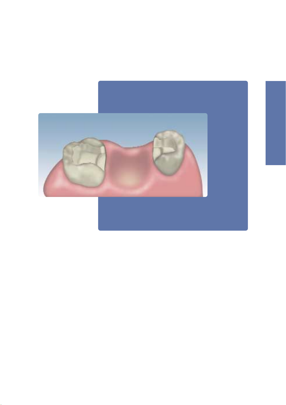
3-
UNIT INLAY-RETAINED BRIDGES
Starting situation
Fabricate a master model or a model with detachable
segments on the basis of the impression in the usual
manner. Expose and mark the preparation margin. It is
advisable to apply a sealer to harden the surface and to
protect the stone die from abrasion. The application of the
sealer must not cause any changes in the dimension of the
stone die. Subsequently, a spacer can be applied, if this is
the customary method of working.
Fabricate a working model.
Page 49

49
3-
UNIT INLAY
-
RETAINED BRIDGES
Fabricating the duplicate model for the vacuum forming process
For inlay-retained bridges, the abutment teeth are cut to obtain an appropriate cavity for the abutment/pontic contact
surface. Consequently, a duplicate model has to be prepared. The master model is utilized to contour the pontic (including
the pontic/abutment contact layer), to check the fit of the restoration and to veneer the framework. Pour the original
impression a second time and create a small duplicate model for the vacuum-forming process. Make sure to eliminate
undercut areas to facilitate the subsequent application of the Transil matrix.
In addition, reduce the cusps of the abutment teeth in such a way that the height of the cavity measures at least 0.5 mm
to enable the Vectris fibres to adapt to the cavity effectively. The height may be marked with a pencil to facilitate the
following reduction.
Fabricate a duplicate model from the original impression and eliminate undercut areas.
Mark the height of the cavity and reduce the cusps.
Completed duplicate model for the vacuum-forming process
–A silicone, polyether or similar material should be used for impression taking as these materials provide an
optimum reproduction of detail. Additionally, the impressions taken with these materials can be poured
several times.
– Hydrocolloid and alginate materials are unsuitable and cannot be poured more than once.
Page 50

50
Contouring the pontic
First, seal the dies with a wax/stone or resin/stone separator. Contour the pontic on the master model in a cusp-supporting
manner similar to the metal-ceramic technique, using wax or composite (Light Tray). This step helps to obtain a
homogeneous layer thickness in the following veneering material. The occlusal abutment/pontic contact area in the cavity
should exhibit the following dimensions:
– cover the entire surface of the cavity
– length of the abutment/pontic area in the cavity: at least 4 mm
– thickness of the contact layer: at least 0.3 mm
– joint face of the connector: at least 3 x 3 mm
Check the pattern in the articulator and adjust as necessary. If a full wax-up has been prepared, the wax rims may be used
for checking purposes.
Contour the pontic on the master model.
Check the pattern in the articulator.
Conduct a final check of the duplicate model and check the dimensions of the pontic.
Tip:
The pontic can be contoured using a tray material (Light Tray) and adjusted by grinding after completion of the
polymerization process.
≥ 0.3 mm
≥ 3 mm
≥ 3 mm
≥ 4 mm
≥ 4 mm
Page 51

51
3-
UNIT INLAY
-
RETAINED BRIDGES
Transferring the pontic to the duplicate model
Transfer the fully contoured pontic to the duplicate model and use a small amount of wax to hold it in place. Block out the
basal surface of the pontic using laboratory silicone (Sil-Tech) in order to ensure that the following Transil matrix can be
removed effortlessly. It is important to block out this area because this determines the way in which the Vectris Frame is
wrapped around the Vectris Pontic. The portion of the basal surface that is in contact with the laboratory silicone should
not be too wide. It is advisable to follow the following instructions to transfer the pontic to the duplicate model:
1. Reduce the basal surface of the duplicate model and prepare retention
2. Transfer the pontic to the duplicate model and use a small amount of wax to hold it in place
3. Block out the reduced basal surface using laboratory silicone (Sil-Tech)
4. Reduce the blocked out area by means of a scalpel or bur
Reduce the basal surface of the duplicate model and transfer the pontic to the model.
Block out the reduced basal surface with laboratory silicone and then reduce the blocked out area.
The basal surface should not be too wide.
Pontic on the duplicate model after completion of the transfer process.
Page 52

52
Fabricating the Transil matrix
Separate the laboratory silicone with a thin coat of Vaseline to prevent the two silicone materials from sticking to each
other. Insert the Transil cartridge into the dispenser, mount a new mixing tip and apply Transil to the die and pontic in a
single step. Transil should be applied in a layer thickness of approx. 3 to 6 mm to obtain sufficient stability. The setting
reaction may be accelerated by using a hot air dryer. After the material has set, smooth out the exterior surface and form it
into a conical shape to enhance the passage of light. Subsequently, remove the Transil matrix from the die.
Apply a thin coating of Vaseline to the laboratory silicone and then apply Transil.
Smooth out the exterior surface of the Transil matrix and form it into a conical shape.
Tip:
A Vectris foil may be used to smooth out the outer surfaces while the matrix material is still soft.
Tip:
In order to facilitate the flowing off of the Vectris matrix matrial, small spillways may be cut into the palatal and labial
portions of the laboratory silicone after the Transil matrix has been removed.
Page 53

53
3-
UNIT INLAY
-
RETAINED BRIDGES
Sealing the dies
After having removed the matrix and cleaned the duplicate
model, apply Vectris Model Separator in two coats. Apply
the first layer slightly more generously than the second one
and make sure to fully cover all areas of the die. Watch out
for sharp edges in particular. Allow the first layer to react
for 3 minutes. Subsequently, apply the second layer of
Vectris Model Separator in a thin coating, invert the model
and allow it to dry for another 3 minutes.
Apply a generous coat of Vectris Model Separator and allow it to dry for approx. 3 minutes.
Apply the second layer of Vectris Model Separator in a thin coating and allow it to dry for
another 3 minutes upside down.
Page 54

54
Schematic of the order in which the individual Vectris strips have to be placed. Moisten the Transil matrix with Vectris Glue.
First, place a short Vectris strip on each cusp … …then place a long Vectris strip to establish the pontic/abutment contact surface…
Placing Vectris Pontic into the Transil matrix and vacuum-forming the pontic
Slightly moisten the Transil matrix with Vectris Glue to facilitate the adaptation of the Vectris Pontic strips. Remove the
Vectris Pontic from the light-protected package, cut it to the desired length, remove it from the foil and place it into the
Transil matrix using tweezers. Insert the individual strips as indicated in the schematic below. Then, place the Transil matrix
on the duplicate model in the correct position, press it into place and mount the model on the model carrier of the
Vectris VS1 framework former. Start Program 1 to commence the vacuum-forming and polymerization process. The
program takes 10 minutes to complete.
Preparing the model for the vacuum-forming process
Before removing the Vectris Pontic from the packaging, adjust the height of the model carrier of the vacuum former so
that the distance to the upper rim of the container is 2 to max. 3 cm. If necessary, the height may be further adjusted with
the help of the spacer rings. Finally, check the position of the membrane.
Page 55

55
Complete the buccal and palatal areas…
… and contour the base surface using short Vectris strips. Then place the pontic on the
duplicate model.
…and a medium-sized Vectris for the area between the bridge abutments.
The vacuum forming and polymerization process takes 10 minutes with Program 1.
3-
UNIT INLAY
-
RETAINED BRIDGES
Page 56

56
Important:
If it is impossible to avoid modifications involving grinding, then sandblast the entire pontic surface with type
100 Al2O3at 1 bar (14.5 psi) pressure.After sandblasting, remove residue by tapping it off and not by cleaning the
surfaces with steam or an air gun. If necessary, a clean disposable brush may be used for this purpose. Apply
Vectris wetting liquid immediately after having removed the residue. Use a disposable brush to apply the liquid
and allow it to react for 60 seconds. Disperse excess material with oil-free compressed air and replace the pontic
on the duplicate model.
Vacuum-forming the Vectris Frame
Remove the Transil matrix but leave the pontic on the duplicate model. Remove any Vectris matrix material that has been
squeezed downwards, using an appropriate instrument. If the pontic inadvertently comes off along with the Transil
matrix, carefully remove it from the matrix and reposition it on the duplicate model. Do not grind the pontic and avoid
contaminating it.
Subsequently, remove the Vectris Frame from the light-protected package and place it on the Vectris Pontic. Do not cut
slits into the Vectris Frame. Place the Transil matrix over the duplicate model, push it into place and position the model
at the centre of the container in the framework former. Start Program 1 to commence the vacuum forming and
polymerization process. The program takes 10 minutes to complete.
Place the Vectris Frame on the pontic; place the Transil matrix over the model and press it into place.
The vacuum-forming process results in an optimum shape and adaptation of the Vectris Frame.
Page 57

57
3-
UNIT INLAY
-
RETAINED BRIDGES
Removing the framework from the die
Upon completion of the vacuum forming process, remove
the Transil matrix and lift the framework from the die. If the
framework cannot be readily removed, warm up the framework and the duplicate model by means of a steam jet and
then try again. Remove excess material using a separating
disk while the framework is still on the model.
Subsequently, carefully remove the framework off the die.
…and carefully remove the framework off the die, using an appropriate instrument.
Remove excess material while the framework is still on the model…
Page 58

58
Finishing
Remove excess material in the marginal areas with cross-cut tungsten carbide burs. It is advisable to use a slow rotational
speed and light pressure. The thickness of the walls, which is 0.3 to 0.4 mm after the vacuum forming process,
must not be reduced by grinding. The pontic/abutment contact layer should cover the entire surface of the cavity.
Remove excess with tungsten carbide burs and fit the restoration into the preparation.
The result
The SR Adoro Instructions for Use provide detailed information on the conditioning and veneering of 3-unit
inlay-retained bridges made of Vectris.
Page 59

59
Page 60

Ivoclar Vivadent AG
Bendererstrasse 2
FL-9494 Schaan
Liechtenstein
Tel. +423 235 35 35
Fax +423 235 33 60
www.ivoclarvivadent.com
Ivoclar Vivadent Pty. Ltd.
1 – 5 Overseas Drive
P. O. Box 367
Noble Park,Vic. 3174
Australia
Tel. +61 3 979 595 99
Fax +61 3 979 596 45
Ivoclar Vivadent Ltda.
Rua Maestro João Gomes de
Araújo 50; Salas 92/94
Sao Paulo, CEP 02332-020
Brasil
Tel. +55 11 69 59 89 77
Fax +55 11 69 71 17 50
Ivoclar Vivadent Inc.
2785 Skymark Avenue, Unit 1
Mississauga
Ontario L4W 4Y3
Canada
Tel. +1-905 238 57 00
Fax +1-905 238 57 11
Ivoclar Vivadent Marketing
Ltd.
Calle 134 No. 13-83, Of. 520
Bogotá
Colombia
Tel. +57 1 627 33 99
Fax +57 1 633 16 63
Ivoclar Vivadent SAS
B.P. 118
F-74410 Saint-Jorioz
France
Tel. +33 450 88 64 00
Fax +33 450 68 91 52
Ivoclar Vivadent GmbH
Dr. Adolf-Schneider-Str. 2
D-73479 Ellwangen, Jagst
Germany
Tel. +49 (0) 79 61 / 8 89-0
Fax +49 (0) 79 61 / 63 26
Ivoclar Vivadent UK Limited
Meridian South
Leicester
LE19 1WY
Great Britain
Tel. +44 116 265 40 55
Fax +44 116 265 40 57
Ivoclar Vivadent s.r.l.
Via dell’Industria 16
I-39025 Naturno (BZ)
Italy
Tel. +39 0473 67 01 11
Fax +39 0473 66 77 80
Ivoclar Vivadent S.A. de C.V.
Av. Mazatlán No. 61, Piso 2
Col. Condesa
06170 México, D.F.
Mexico
Tel. +52 (55) 55 53 00 38
Fax +52 (55) 55 53 14 26
Ivoclar Vivadent Ltd
12 Omega St, Albany
PO Box 5243 Wellesley St
Auckland, New Zealand
Tel. +64 9 914 9999
Fax +64 9 914 9990
Ivoclar Vivadent Polska
Sp. z.o.o.
ul. Jana Pawla II 78
PL-01-501 Warszawa
Poland
Tel. +48 22 635 54 96
Fax +48 22 635 54 69
Ivoclar Vivadent S.A.
c/Emilio Muñoz, 15
Esquina c/Albarracín
E-28037 Madrid
Spain
Tel. + 34 91 375 78 20
Fax + 34 91 375 78 38
Ivoclar Vivadent AB
Dalvägen 16
S-169 56 Solna
Sweden
Tel. +46 8 514 93 930
Fax +46 8 514 93 940
Ivoclar Vivadent, Inc.
175 Pineview Drive
Amherst, N.Y. 14228
USA
Tel. +1 800 533 6825
Fax +1 716 691 2285
Ivoclar Vivadent – worldwide
Date information prepared: 01/2004
These materials have been developed solely for use
in dentistry. Processing should be carried out
according to the Instructions for Use. Liability cannot
be accepted for damages resulting from failure to
observe the Instructions or the stipulated area of
application. The user is responsible for testing the
material for its suitability for any purpose not
explicitly stated in the Instructions. Descriptions and
data constitute no warranty of attributes and are
not binding.
Printed in Liechtenstein
© Ivoclar Vivadent AG, Schaan / Liechtenstein
579628/0104/0.5/e/BVD
 Loading...