

Page 1
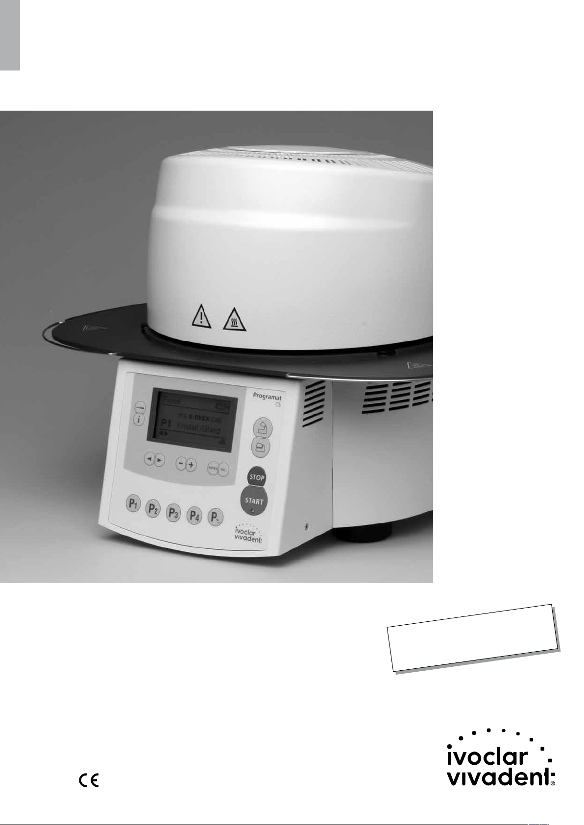
Programat® CS
Operating Instructions
Valid as of
Software Version 2.0
Page 2

2
Page 3

Table of Contents
Views of the Furnace, List of Parts 4
1. Introduction / Signs and Symbols 8
1.1 Preface
1.2 Introduction
1.3 Notes regarding the Operating Instructions
1.4 Notes on the different voltage versions
2. Safety First 9
2.1 Indications
2.2 Health and safety instructions
3. Product Description 12
3.1 Components
3.2 Hazardous areas and safety equipment
3.3 Functional description
3.4 Accessories
3.5 Indication/Contraindication
4. Installation and Initial Start-Up 13
4.1 Unpacking and checking the contents
4.2 Selecting the location
4.3 Assembly
4.4 Dismounting the furnace head
4.5 Initial start-up
5. Operation and Configuration 18
5.1 Introduction to the operation
5.2 Explanation of the key functions
5.3 Basic meaning of the display information
5.4 Program structure
5.5 Adjustable parameters and possible value ranges
5.6 Settings / test programs and information
5.7 Explanation of the symbols on the display
5.8 Explanation of the beeper signals
6. Practical Use 23
6.1 Switching on/off
6.2 Firing using a standard program
6.3 Firing using an individual program
6.4 Other options and special features of the furnace
6.5 Programming
7. Maintenance, Cleaning and Diagnosis 25
7.1 Monitoring and maintenance
7.2 Cleaning
7.3 Diagnosis program
8. What if ... 27
8.1 Error messages
8.2 Additional error messages
8.3 Technical malfunctions
8.4 Repair
9. Product Specifications 30
9.1 Delivery form
9.2 Technical data
9.3 Acceptable operating conditions
9.4 Acceptable transportation and storage conditions
10. Appendix 31
10.1 Program table
10.2 Program structure
3
Page 4

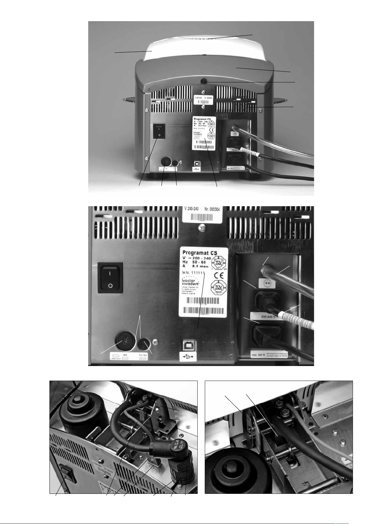
List of Parts
Front view:
1 Sealing surface
2 Furnace head sealing ring
3 Insulation
4 Thermocouple
5 Firing plate
6 Display
7 Frame plate
8 QTK heating muffle
9 Furnace housing
10 Keypad
11 On/Off switch
12 Heating element fuse
13 Vacuum pump fuse
14 USB-Device interface
15 Fuse holder
16 Power cord
17 Power socket
18 Vacuum pump socket
19 Rating plate
20 Thermocouple cable
21 Vacuum hose connection
23 Rubber feet
24 Firing plate holder
25 Furnace head housing
26 Thermocouple plug
27 Plug fuse
28 Heater plug
29 Heater plug socket
30 Thermocouple plug socket
32 Leaf spring
33 Air vents (base)
34 Cooling tray
35 Screw for cooling tray
36 Hood
37 Knurled screw for hood
38 Air vents furnace head
39 Air vents rear panel
40 Warnings
41 Furnace head mounting mark
42 Furnace base mounting mark
43 Furnace head mounting
44 Quartz-glass tube
46 Vacuum hose
47 Silicone rest
48 Connecting rod
49 Plug-in console
4
Page 5

40
10
25
6
47
35
34
23
33
4
2
5
7
1
8
3
24
9
5
Page 6
25
38
36
37
39
12
11
15
13
12
13
19
21
46
17
16
18
19
20 26 30 29
32
49
48
27 28 11
6
43
Page 7
8
4
44
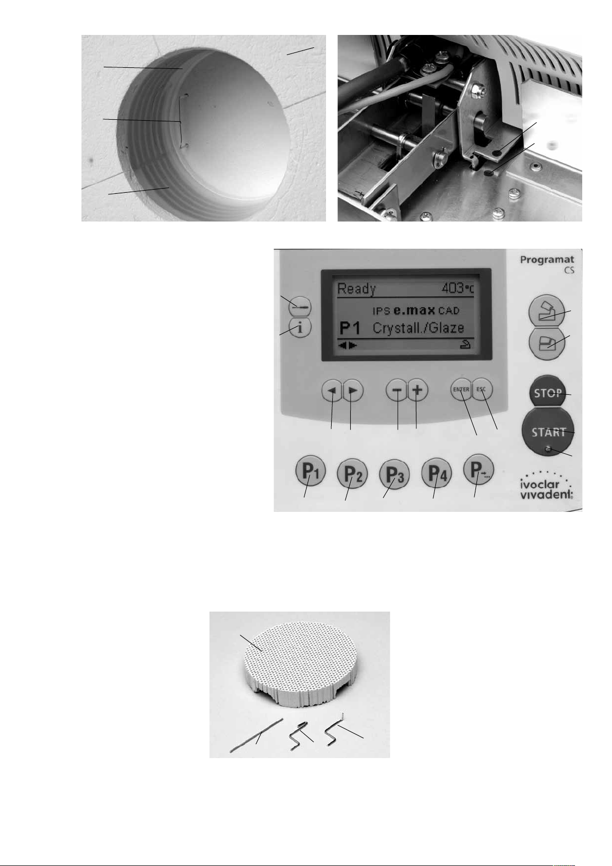
Control unit:
71 ESC key
72 ENTER key
73 START key
74 Start LED
75 STOP key
76 + key
77 – key
78 Settings key
79 Cursor key right
80 Cursor key left
81 Information key
82 Program 1
83 Program 2
84 Program 3
85 Program 4
86 Next program
87 Open furnace head
88 Close furnace head
78
81
82
3
7980 77
83
84
76
85
86
72
71
49
48
41
42
87
88
75
73
74
100 Programat firing tray
101 Metal pin A
102 Metal pin B
103 Metal pin C
100
102
103
101
7
Page 8
1. Introduction / Signs and Symbols
1.1 Preface
Dear Customer
Thank you for having purchased
the Programat CS. It is a
state-of-the-art furnace for the
dental practice, which requires a
furnace for the CAD/CAM
technique. The Programat CS
enables glaze and crystallization
firings for the CAD/CAM
technology. This furnace has
been specially developed for
this purpose.
The furnace has been designed
according to the latest industry
standards. Inappropriate use
may damage the equipment and
be harmful to personnel. Please
observe the relevant safety
instructions and read these
Operating Instructions carefully.
Enjoy working with the CS.
1.2 Introduction
The signs and symbols in these
Operating Instructions facilitate
the finding of important points
and have the following
meanings:
Risks and dangers
Important
information
Contraindication
Burn hazard
Risk of crushing
The Operating
Instructions must
be read
1.3 Notes regarding the
Operating Instructions
Furnace concerned:
Programat CS
Target group:
Dentists and dental
technologists
These Operating Instructions
facilitate the correct, safe, and
economic use of the Programat
CS furnace.
Should you lose the Operating
Instructions, extra copies can be
ordered at a nominal fee from
your local Ivoclar Vivadent
Service Center or downladed
from www.ivoclarvivadent.com/
downloadcenter.
1.4 Notes on the different
voltage versions
The furnace is available with
different voltage versions.
– 100 V / 50–60 Hz
– 110–120 V / 50–60 Hz
– 200–240 V / 50–60 Hz
In the Operating Instructions,
the furnace is described in the
200-240 V voltage version.
Please note that the voltage
range shown on the images
(e.g. rating plate) may differ
depending on the voltage
version of your furnace
8
Page 9
2. Safety First
This chapter is especially important for personnel who work with the
Programat CS or who have to carry out maintenance or repair work.
This chapter must be read and the corresponding instructions followed.
2.1 Indications
The Programat CS must only be used to fire dental ceramic materials
and it should be used for this purpose only. Other uses than the
ones stipulated, e.g. cooking of food, firing of other materials, etc.
are contraindicated. The manufacturer does not assume any liability
for damage resulting from misuse. The user is solely responsible for
any risk resulting from failure to observe these Instructions.
Further instructions to assure proper use of the furnace:
– The instructions, regulations, and notes in these Operating
Instructions must be observed.
– The instructions, regulations, and notes in the material’s
Instructions for Use must be observed.
– The furnace must be operated under the indicated environmental
and operating conditions (Chapter 9).
– The Programat CS must be properly maintained.
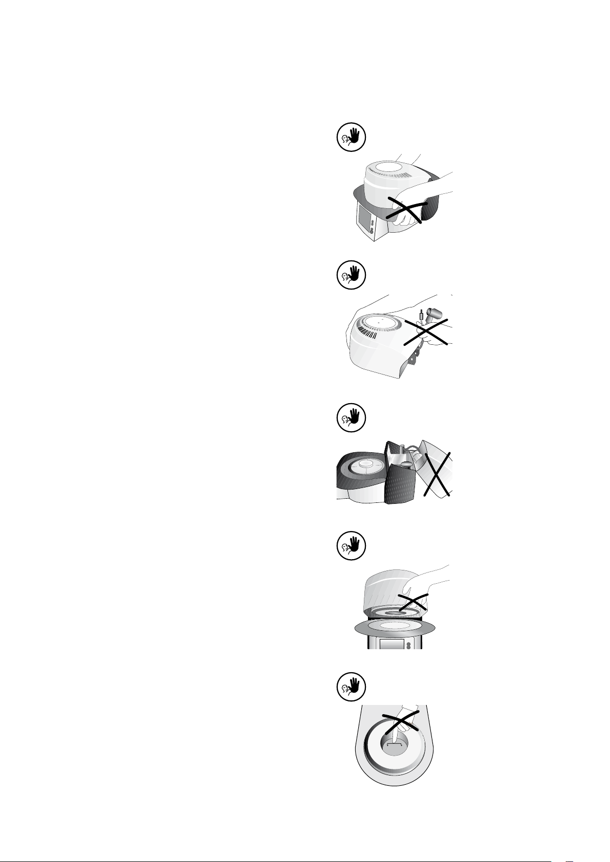
2.1.1
Contraindication
Do not carry the furnace head by
the cooling tray.
2.1.2
Contraindication
Do not carry the furnace head by
the cables, since the cables and
connections may be damaged.
2.1.3
Contraindication
2.1.4
Contraindication
2.1.5
Contraindication
The furnace head should not be
removed from the furnace base as
long as the furnace head is
connected by means of the
heater cable.
The furnace has an electric drive
and must be operated by means
of the electronic controls. Never
open the furnace head by hand,
since the mechanism will be
damaged.
Do not touch the thermocouple
and the quartz tube in the firing
chamber. Avoid contact with the
skin (grease contamination), as
the parts will be prematurely
damaged.
9
Page 10
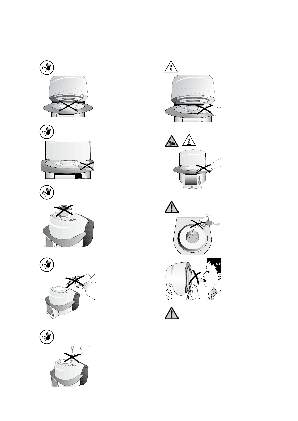
2.1.6
Contraindication
2.1.7
Never use the furnace without a
firing table.
2.1.11
Risks of burn hazard
Never place objects in the firing
chamber by hand, since there is a
burn hazard. Always use the tongs
(accessories) supplied for this purpose. Never touch the hot surface
of the furnace head, as there is a
burn hazard. Please also refer to
the warnings on the furnace.
Contraindication
2.1.8
Contraindication
2.1.9
Contraindication
Firing trays must not be placed in
the area surrounding the firing
table, since this will obstruct the
closing of the furnace head.
Foreign objects must not be
placed on the furnace head or the
air vents. Make sure that no liquids or other foreign objects enter
the air vents, since this may result
in an electrical shock.
Make sure that no liquids or other
foreign objects enter the furnace.
2.1.12
Risk of crushing and burn hazard
Never reach under the furnace
head with the hand or other parts
of the body during operation,
since there is a risk of crushing
and a burn hazard.
2.1.13
Risks and dangers
This product contains ceramic
fibres and may release fibre dust.
Do not use compressed air, or
blow, on the furnace thus
distributing the dust in the
environment and observe the
additional notes on page 11.
2.1.10
Contraindication
Do not insert any foreign objects
into the air vents. There is a risk of
electrical shock.
2.1.14
Risks and dangers
The furnace must not be operated if the quartz tube in the firing
chamber is damaged. There is a risk of electric shock upon contact
with the heating wire.
10
Page 11

2.2 Health and Safety Instructions
This furnace has been designed according to EN 61010-1 and has
been shipped from the manufacturer in excellent condition as far as
safety regulations are concerned. To maintain this condition and to
assure risk-free operation, the user must observe the notes and
warnings contained in these Operating Instructions.
– The user must especially become familiar with the warnings and
the operating conditions to prevent injury to personnel or damage
to materials. The manufacturer is not responsible for damage
resulting from misuse or failure to observe the Operating Instructions. Warranty claims cannot be accepted in such cases.
– Before switching on the furnace, make sure that the voltage
indicated on the rating plate complies with your local power
supply.
– The power socket must be equipped with a residual current circuit
breaker.
– The furnace must be plugged into a socket with protected
contacts.
– Place furnace on a fire-proof table (observe local regulations, e.g.
distance to combustible substances or objects, etc.)
– Always keep the air vents at the rear and the side of the furnace
free from obstruction.
– Do not touch any parts that become hot during the operation of
the furnace. There is a burn hazard!
– Clean furnace only with a dry or slightly moist cloth. Do not use
any solvents! Disconnect power before cleaning.
– The furnace must be cool before it is packed for transportation
purposes.
– Use original packaging for transportation purposes.
– Before calibration, maintenance, repair, or exchange of parts, the
power must be disconnected if the furnace is to be opened.
– If calibration, maintenance, or repair has to be carried out with
the power connected and the furnace open, only qualified
personnel, who are familiar with the risks and dangers, may
perform these procedures.
– After maintenance, the required safety tests (high voltage
resistance, protective conductor, etc.) have to be carried out.
– Ensure that only fuses of the indicated type and rated current are
used.
– If it is assumed that safe operation is no longer possible, the
power must be disconnected to avoid accidental operation.
Safe operation is no longer possible if
– the furnace is visibly damaged
– the furnace does not work
– the furnace has been stored under
unfavourable conditions over an extended period of time
– Use only original spare parts.
– The temperature range for faultless operation is +5 °C to +40 °C
(+41 °F to +104 °F).
– If the furnace has been stored at very low temperatures or high
atmospheric humidity the head has to be opened and the unit
dried or left to adjust to room temperature for approx.
1 hour (do not connect the power yet).
– The furnace has been tested for use at altitudes of up to 2000 m
(6562 ft) above sea level.
– The furnace may only be used indoors.
Any disruption of the protective conductor either inside
or outside the furnace or any loosening of the protective
conductor connection may lead to danger for the user in
case of malfunction. Deliberate interruptions are not
tolerated.
Materials developing harmful gases must not be fired.
Warnings regarding the dismounting of the heating muffle
This product contains ceramic fibres and may release fibre
dust. Fibre dust has proved to be carcinogenic in animal
experiments. The corresponding EU Safety Data Sheet must
be observed.
The heat insulation of the firing chamber in the Programat CS
consists of ceramic fibres. After prolonged use of ceramic fibres at
temperatures of over 900 °C (1652 °F), silicogenic substances
(Cristobalite) may be produced. In certain cases, e.g. upon changing
of the heating muffle, the possible resulting dust exposure may
cause irritation of the skin, eyes, and respiratory organs. Therefore,
proceed as follows when changing the heating muffle:
– Make sure the corresponding staff wears long-sleeved clothing, as
well as headgear, goggles, and gloves.
– Place suction equipment at the source of the dust or, if not
possible, provide the staff with FFP3 facemasks or similar items.
– Once the procedure has been completed, any dust possibly
adhering to exposed skin must first be rinsed off with cold water.
Only after that should soap and warm water be used.
– The corresponding work clothes should be washed separately.
Warning
The insulation on this product contains refractory ceramic fibres (RCF)
which pose a possible cancer hazard, if agitated and inhaled. May be
irritating to the skin, eyes or respiratory tract if insulation is cracked
or corrupted.
California Proposition 65
Warning: ”This product contains Refractory
Ceramic Fibres, a substance known to the State of California to
cause cancer.”
Disposal:
The furnaces must not be disposed of in the normal
domestic waste. Please correctly dispose of old
furnaces according to the corresponding EU council
directive. Information on the correct disposal may
also be found on your local Ivoclar Vivadent
homepage.
11
Page 12

3. Product Description
3.1 Components
The Programat CS comprises the
following components:
– Furnace base with electronic
controls
– Furnace head with firing
chamber
– Firing table
– Cooling tray
– Power cord and hose for
vacuum pump
– Vacuum pump (accessory)
3.2 Hazardous areas and safety equipment
Description of the risk areas of the furnace:
Hazardous area Type of risk
Firing chamber Risk of burning
Opening/closing mechanism Risk of crushing
Electrical components Risk of electrical shock
Description of the safety equipment of the furnace:
Safety equipment Protective effect
Protective conductor Protection from electrical shock
Electrical fuses Protection from electrical shock
3.3 Functional description
The firing chamber may be heated up to max. 1200 °C (2192 °F) by
means of a heating element. Furthermore, the firing chamber has
been designed in such a way that a vacuum may be created with a
vacuum pump. The firing process is controlled with the
corresponding electronic controls and a software. Moreover,
the set and actual temperatures are continuously compared.
3.4 Accessories
(not part of the delivery form)
– Automatic Temperature Checking Set 2 (ATK 2)
– Programat Accessories Set (large and small firing trays, firing
tongs, Temperature Checking Set)
– Vacuum pump
3.5 Indication/Contraindication
Indication
– Glaze and crystallization firings (chairside area)
Contraindication
– The Programat CS is not suitable as ceramic furnace for dental
laboratories
12
Page 13

4. Installation and Initial Start-Up
4.1 Unpacking and checking the contents
The packaging provides the following advantages:
– Reusable packaging
– Closing mechanism with integrated transporta-tion grips
– Ideal protection by Styrofoam inserts
– Easy handling / optimum unpacking
– The packaging may be used in several ways (modules)
Remove the furnace components from their
packaging and place it on a suitable table. Please observe the
instructions on the outer packaging.
There are no special transportation grips on the furnace. Support the
bottom of the furnace to carry it.
4.2 Selecting the location
Place the furnace on a flat table using the rubber feet. Make sure
that the furnace is not placed in the immediate vicinity of heaters or
other sources of heat. Make sure that air may properly circulate
between the wall and the furnace.
Also ensure that there is enough space between the furnace and the
user, as the furnace releases heat during the opening of the furnace
head.
The furnace should neither be placed nor operated in areas
where there is an explosion hazard.
4.3 Assembly
Make sure the voltage indicated on the rating plate (19) complies
with the local power supply. If this is not the case, the furnace must
not be connected.
Check the delivery for completeness (see delivery form in Chapter 9)
and transportation damage. If parts are damaged or missing, contact your local Ivoclar Vivadent Service Center.
Packing and shipping of individual components:
The packaging of the Programat CS permits simple and safe shipping
of individual components. Simply use the two corresponding inserts.
Fold the side flaps (2) and combine the two packaging parts by
means of the transportation flaps. The packaging may be disposed
with the regular household refuse.
We recommend keeping the original packaging for future
service and transportation purposes.
19
Step 1:
Assembling the cooling tray (34)
Remove both screws (35) including the silicone washer (47) for the
cooling tray (34).
35
35
47
47
13
Page 14

Place the cooling tray (34) on the frame plate (7).
Make sure that the cooling tray (34) is correctly
positioned on the frame plate (7).
Secure the cooling tray (34) with the two screws
(35) including the silicone washer (47).
7
34
Step 2:
Placing the firing plate (5)
Place the firing plate (5) on the firing plate holder
(24).
35
47
5
24
14
Page 15

Step 3:
Mounting the furnace head
The complete furnace head is best mounted with
the rear panel of the furnace pointing towards the
user. Lift the furnace head with both hands (see
picture) and carefully position it on the furnace
head mounting.
Ensure that the furnace head mounting mark (41)
is aligned with the furnace base mounting mark
(42).
Make sure that the firing plate (5) is
not damaged by mounting the furnace
head.
49
Step 4:
Connections
Connect the cables of the furnace head with the
furnace base. Proceed as follows:
– Insert the thermocouple plug (26) (make sure
that the polarity of the plug is correct)
– Insert the heater plug (28)
48
41
42
28
15
26
30
27
Page 16

Secure the heater plug (28) with the plug fuse (27)
by turning it until the heater plug (28) has been
secured.
Step 5:
Mounting the hood (36)
Once all cables are properly connected to the
furnace base, the hood (36) can be mounted.
Subsequently, secure the hood with the knurled
screw (37).
27
28
The furnace may only be operated with
the hood mounted.
Step 6:
Establishing additional connections
Power connection
Please make sure that the voltage indicated on the
rating plate complies with the local power supply.
Connect the power cord (16) with the power
socket (17) of the furnace.
Vacuum pump connection
Connect the vacuum pump plug with the vacuum
pump socket (18).
We recommend using only the VP3 easy or VP4
vacuum pumps from Ivoclar Vivadent, since these
pumps are especially coordinated with the furnace.
If other pumps are used, please observe and do not
exceed the maximum power consumption.
1 2 3
21
46
17
16
15
19
18
12
13
16
Page 17

4.4 Removing the furnace head
Before the hood (36) is removed, the furnace has
to be switched off and the power cord (16)
disconnected from the power socket (17).
1. Loosen and remove the knurled screw (37) of
the hood (36)
2. Remove the hood (36)
3. Disconnect the thermocouple plug (26)
4. Disconnect the heater plug (28)
5. Press the leaf spring (32) with a finger, lift off
the furnace head at the same time and
remove it
Make sure the furnace head has
completely cooled down before it is
removed (fire hazard).
4.5 Initial start-up
1. Connect the power cord (16) with the wall
socket.
2. Put the On/Off switch (11) at the rear of the
furnace on position “I”.
Stand-by mode
The stand-by mode is indicated after the self-test.
The furnace is set to the last used program.
The furnace will now automatically conduct a selftest. The performance of all furnace components is
automatically checked. The display shows the
following indications during the self-test:
3
1
4
2
1 Status bar
2 Firing hours
3 SW version
4 Current supply voltage
92
90
93
90 Program number
91 Current temperature
92 Status of furnace
93 Program name
94 Material name
91
94
If any component is defective, the corresponding
error number (ER xxx) will be indicated in the
display. If all components work properly, the
display shows the stand-by mode.
17
Page 18

5. Operation and configuration
5.1 Introduction to the operation
The Programat CS is equipped with a graphical display with backlighting. By means of the enter keys and the command keys (B), the
furnace may be programmed and controlled.
78
81
7980 77
B
82
83 84 85 86
7176
72
87
88
75
73
74
5.2 Explanation of key functions
– Settings key (78)
After pressing the ‚Settings‘ key, the settings of the furnace can
be displayed and/or changed one after the other.
– Information key (81)
After pressing the ‚Information‘ key, the information about the
furnace can be displayed one after the other.
– Cursor keys (79, 80)
By pressing the cursor keys in the stand-by mode, the program
can be changed.
The cursor keys can be used to browse through the settings and/
or information. In the list of parameters, the current cursor posi-
tion is indicated by an illuminated (non-blinking) frame around the
numerical value.
– – / + keys (76, 77)
Changing the settings or entry of a numerical value are carried
out using the –/+ keys. Each individual entry by means of the ‚–‘
or ‚+‘ key is immediately accepted, provided the corresponding
value range is observed. Once the limit of the value range is
reached, the value is no longer adjusted.
– ESC key (71)
This key is used to close an error indication. Moreover, any screen
can be left by pressing this key.
– ENTER key (72)
This key is used to select settings or confirm entries.
– START key (73)
Pressing this key starts the selected program. Starting a program is
only possible with the furnace head open.
– Start LED (74)
Illuminated if a program has been started. The LED is blinking
while a program is paused.
– STOP key (75)
Pressing this key once (program paused)
Pressing this key twice (program will be interrupted and vacuum
flooded). With the STOP key the movement of furnace head and
the beeper will be interrupted, too.
– Open furnace head key (87)
The furnace head is opened (not possible during a program in
progress).
– Close furnace head key (88)
The furnace head is closed (not possible during a program in
progress).
– Program 1 key (82)
Used to select Program 1 (P1) (not possible during a program in
progress).
– Program 2 key (83)
Used to select Program 2 (P2) (not possible during a program in
progress).
– Program 3 key (84)
Used to select Program 3 (P3) (not possible during a program in
progress).
– Program 4 key (85)
Used to select Program 4 (P4) (not possible during a program in
progress).
– Next program key (86)
Used to select the next program (P5, P6, …) (not possible during a
program in progress).
5.3 Basic meaning of the display information
– Stand-by mode
Furnace and/or
program status
Main area
In the main area, the most
important information
(e.g. the currently selected
program) is shown.
– Firing curve display
Furnace and/or
program status
Main area
Currently selected
program
Status area
Recommendation
area
Status area
Current temperature
of the furnace
The most likely action to
follow is indicated
(keystroke).
Current temperature
of the furnace
Remaining time
Status bar
18
Page 19

5.4 Program structure
The furnace offers three types of programs:
a. Standard programs for Ivoclar Vivadent materials
b. Free programs
c. Test programs
a) Standard programs for Ivoclar Vivadent
materials (see chapter 10.1)
– IPS e.max CAD
– IPS Empress CAD
b) Free programs
All free programs are available as equivalent
and thus fully-fledged programs. All the
parameters can be individually set for each
program.
When the furnace is delivered ex
works, the standard programs already
contain the recommended material
parameter settings.
However, the parameters can be changed and
overwritten at any time, if required, if the
programs are to be used for other purposes.
Therefore, the 50 programs are also available as
free programs.
The programs are designed in such a way that
they can be either used as conventional, one-stage
programs or as two-stage programs, if required.
The mode can be changed via the symbol (one- or
two-stage program) by using the + or – key.
c) Test programs
Various test programs are available. Please refer
to chapter 5.5 Settings / configuration and
information.
5.5 Adjustable parameters and possible value ranges
Symbol Parameter Value range Value range
P Program number P 1–20
B Stand-by temperature 100–700 °C 212–1292 °F
S Closing time (min : sec) 00:18–30:00
t➚ (*) Temperature increase rate 30–140 °C/min 54–252 °F/min
T Holding temperature 100–1200 °C 212–2192 °F
H Holding time (min : sec) 00.01–60:00
V1 Vacuum on 0 or 1–1200 °C 0 or 34–2192 °F
V2 Vacuum off 0 or 1–1200 °C 0 or 34–2192 °F
t➚ (*) Temperature increase rate
t2➚ Second stage 30–140 °C/min 54–252 °F/min
T Holding temperature
Second stage 100–1200 °C 212–2192 °F
H Holding time
Second stage (min : sec) 00.01–60:00
V1 (V1 2) Vacuum on
Second stage 0 or 1–1200 °C 0 or 34–2192 °F
V2 (V2 2) Vacuum off
Second stage 0 or 1–1200 °C 0 or 34–2192 °F
L Long-term cooling 0 or 50–1200 °C 0 or 122–2192 °F
tL Cooling temperature rate 0 or 1–50 0 or 32–90
(*) 100 V Version: 140°C/min (252°F/min)
Automatic plausibility check
The furnace is equipped with an automatic plausibility check function. The parameters
(e.g. T 960 but L 1000) are checked upon each program start. In case of contradictory
parameter combinations, the program stops automatically and the respective error
number is indicated.
Examples of firings
– Typical glaze firing
– Typical crystallization firing
19
Page 20

5.6 Settings / test programs
By pressing the „Settings“ key (78), the Settings will be displayed
(indication of the last selected Settings).
Settings
Renaming
Display Short description
Enables the renaming
of the currently
selected program. *
Enables the renaming
of the materials.
The cursor keys (79, 80) are used to toggle between the possible
settings. This screen can be exited with the ESC key (71) or a
Program key (82, 83, …).
5.6.1 Settings / Configuration
Settings
Contrast
Display Short description
The contrast can be
set by means of the
+ or – keys
Temperature mode
The + and – keys can
be used to switch
from °C to °F
Language selection
Enables language
selection
User calibration
value
This program is
suitable to conduct
the temperature
calibration by means
of the ATK 2. The
furnace head opens
automatically if the
Enter key is pressed.
Now insert the
ATK 2 sample in the
intended hole (see
7.6 Temperature
calibration) and start
the program by
means of the
START key.
Volume
Beeper tune
The desired volume
can be set by means
of the + or – keys
The tune can be set
by means of the + or
– keys
Time
Date
General write
protection
Vacuum test
program
Heating muffle test
program
Key test
Cleaning program
Dehumidification
program
The time can be
entered by using the
– / + keys
The date can be
selected by using the
– / + keys
Enables activation or
deactivation of the
general write
protection by means
of the ‚-/+‘ keys once
the user code has
been entered.
Allows to check the
vacuum quality of
the system
Allows to check the
heating muffle. The
result is shown in
graphical form after
the end of the
program
Allows to check the
keypad
The program is used
to clean the heating
muffle and the
insulation materials
by a heat process.
Permits the
dehumidification of
the furnace
Programming
Enables the programming of the
parameters of the
currently selected
program. *
* Some programs are protected with a code. If there will be necessary changes, you will be
informed about the corresponding code.
20
Page 21

Settings
“Ivoclar Vivadent
optimized
temperature control
function“
Selection of factory
settings
Important information
The user code (6725) is required for some settings.
Display
Short description
Only after entry of
the STD code.
Enables the deactivation of the “Ivoclar
Vivadent optimized
temperature control
function“
With this setting, all
values and parameters can be reset
to the factory
settings.
Attention:
All individual programs which have
been created and
saved will be deleted
with this function.
5.5.2 Information
By pressing the ‚Information‘ key (81), you can access the information display (the latest information selected is being displayed). You
can browse through the various information using the cursor keys
(79, 80). You can exit this display by hitting ESC (71) or one of the
program keys (82, 83, …).
Settings
Serial number
Software version
Furnace head
firing hours
Operating hours
furnace
Display Short description
Serial number of the
furnace
Operating hours
vacuum pump
Latest start of
calibration program
Calibration value
Supply voltage
Error list
Calibration value
660°C and 963°C
Shows the current
supply voltage
Enables the display
of the latest error
messages.
21
Page 22

5.7 Symbols in the display 5.8 Explanation of beeper tunes
Symbol name Meaning Symbol
“One-stage Indicates that a conventional,
program“ one-stage program is used
“Two-stage Indicates that a specific,
program“ two-stage program is used.
The bold line indicates the
values for the first stage
“Two-stage Indicates that a specific,
program“ two-stage program is used.
The bold line indicates the
values for the second stage
Furnace head Is shown in the recommendation
open area and indicates the most likely
action to follow.
Furnace head Is shown in the recommendation
close area and indicates the most likely
action to follow.
Press START Is shown in the recommendation
area and indicates the most likely
action to follow.
Beeper description
Beeper lasting for approx.
2 seconds with unchangeable
“Self-test signal” to indicate
the completion of the self-test.
Beeper lasting for approx.
5 seconds with the beeper
signal set by the user.
Beeper with unchangeable
“error tune”.
A short beeper signal will
sound every time a key is
pressed (approx. 0.5 seconds
ON) basically at the volume set
by the user. If the volume is set
to OFF, then the signal sounds
at a medium volume.
* The beeper can be interrupted by means of the STOP key.
Explanation
Self-test has been completed
The firing process has been
completed and the furnace
head is open *.
Error messages are supported
by the error tune *
Keypad test active
Press STOP Is shown in the recommendation
area and indicates a possible
action.
Press ENTER Is shown in the recommendation
area and indicates a possible
action.
Press ESC Is shown in the recommendation
area and indicates a possible
action.
Using Is shown in the recommendation
cursor keys area and indicates a possible
action.
Using – / + Is shown in the recommendation
keys area and indicates a possible
action.
General Indicates in the parameter list
write protection that the general write protection
has been activated by means of
the user code.
Individual Indicates in the parameter list that
write protection the individual write protection
activated
Individual Indicates in the parameter list
write protection that this program is not
not activated write-protected
has been activated for this program
22
Page 23

6. Practical Use
The operating procedure for the Programat CS will be explained with
the help of two examples: one standard and one individual
program.
6.1 Switching on/off
Put ON/OFF switch (11) on position “I”. The furnace conducts an
automatic self-test, which will be indicated in the beginning.
Subsequently, a status bar shows that the self-test is being
conducted. Make sure that the furnace is not manipulated during
this time.
6.1.1 Stand-by mode
After successful completion of the self-test, the Stand-by mode is
shown in the display.
While the furnace heats up to the stand-by temperature the status is
shown in „Preparing“.
As soon as the stand-by temperature has been reached, the status
indication changes to „Ready“. Furthermore, the ‚open furnace
head‘ symbol is shown in the recommendation area, thus indicating
the most likely action to follow.
After the furnace head has been
opened and the object placed, the
program may be started by pressing
the START key. For that purpose,
the START symbol is indicated in
the recommendation area. The
program can only be started if the
furnace head is open.
6.1.2 Description of the firing curve display
If the program is started with the START key, the firing curve display
is shown.
a)
b)
d)
e)
The following information is always displayed:
a) Status of program
b) Remaining time
c) Current temperature
d) Program number
e) Program name
f) Status bar
c)
f)
6.2 Firing using a standard program
Step 1:
Select with the program keys the desired program (1 to 50)
according to the firing table.
Step 2:
Open the furnace head with the “Open furnace head” key (87) and
place the object on the firing tray in the furnace.
Step 3:
Press the START key (73). The program can only be started with the
furnace head open. The process is indicated in the firing curve
display.
6.3 Firing using an individual program
Step 1:
Select a free program.
Step 2:
Select the parameter list via the
setting ‚Programming‘ (7/20) and
change the program parameters
using the ‚–/+‘ keys. After that,
change back to the Stand-by screen
by pressing ESC or the Program
key.
Step 3:
Now, open the furnace head using
the ‚Open furnace head‘ key (87)
and position the firing tray with the
object in the furnace. Press the
START key (73) and the program is
started. The program can only be
started if the furnace head is open.
The sequence can be observed on
the firing curve screen.
6.4 Further possibilities and special features of the
furnace
6.4.1 General write protection
If all programs are write-protected, a closed, black lock appears.
The setting ‚Renaming‘ cannot be selected if the general write
protection is activated. As an indication, a closed lock is shown next
to the keyboard symbol.
6.4.2 Stopping the running program
Press the STOP key once to pause a running program. The green LED
in the START key blinks. Furthermore, the status indicated is ‘Pause’.
Press the STOP key twice to completely stop the program or press
START to continue.
6.4.3 Individual program write protection
For the standard programs, the individual program write protection
is activated as part of the factory settings. In this way, accidental
change of the parameters is prevented.
The individual program write protection (symbol) can be changed for
each program individually via the setting ‚Programming‘ (7/20) using
the ‚+/.‘ keys.
6.4.4 Renaming
The keyboard can be selected via the setting ‚Renaming‘ (8/20,
9/20), provided that the currently selected program is not writeprotected. The desired letters can be selected using the cursor keys
(circulating). The letter is selected with the ENTER key. Individual
letters can be deleted using the ‚delete‘ key (arrow symbol). The
changes are saved using the ‚save‘ key (disk symbol) or the ESC key.
With this action, the keyboard display is also exited.
This key enables the shift to lower case letters, numbers/
symbols and back to upper case
letters.
23
Page 24

6.5 Programming
One-stage program *
The parameter list can be selected via the setting ‚Programming‘
(7/19). In this list, all the program parameters are shown. The desired
parameter can be selected using the cursor keys. The value can be
changed using the ‚-/+‘ keys. This screen can be exited with the ESC
or the Program keys.
If the cursor is on the symbol
‚one-stage‘, pressing the ‚-/+‘
keys allows to switch from a
one-stage program to a twostage program.
Two-stage program
If a two-stage program is used, the parameters are displayed for the
first and the second stage in a separate screen. Switching between
the two screens is carried out using the symbol ‚Change program
stage indication‘.
stage 1 is shown stage 2 is shown
Symbol ‚Change program stage indication‘
If the cursor is on the symbol ‚Change program stage indication‘,
pressing the ‚ENTER‘ key results in a change of the program stage
indication.
If the cursor is on the symbol ‚one-stage/two-stage‘, pressing the
‚-/+‘ keys allows to switch from a two-stage program to a one-stage
program.
* The programs are protected with a code. If there will be necessary changes, you will be
informed about the corresponding code.
24
Page 25

7. Maintenance, Cleaning, and Diagnosis
This chapter describes the user maintenance and cleaning procedures
for the Programat CS. All the other tasks must be performed by
qualified service personnel at a certified Ivoclar Vivadent Service
Center.
7.1 Monitoring and maintenance
The time for these maintenance procedures depends on the
frequency of use and the working habits of the users. For that
reason, the recommended times are only approximations.
What Part When
Check all plug-in connections for correct fit Var. external connections weekly
Check if the furnace head opens smoothly and without excessive noise. Opening mechanism monthly
Check if the thermocouple is straight and in the right place. Thermocouple (4) weekly
Check the insulation for cracks and damages. If the insulation is worn down
it has to be replaced by a certified Ivoclar Vivadent Service Center. Fine hairline cracks on the surface of the insulation are harmless and do not
influence the function of the furnace in a negative fashion.
Check if the sealing rims of the furnace head and the furnace base are clean
and undamaged.
Check the keypad for visible damage. If the keypad is damaged, it has to be
replaced by a certified Ivoclar Vivadent Service Center.
Check temperature.
Use the temperature checking set to check and adjust the temperature in
the furnace.
Check the quartz glass cylinder to make sure the quartz glass is not
defective.
This furnace has been developed for typical use in dental
laboratories. If the product is used in a production
enterprise, for industrial applications, and for continuous
use, premature ageing of the expendable parts has to be
expected.
The expendable parts are as follows:
– Heating muffle
– Insulation material
Expendable parts are not covered by the warranty. Please also
observe the shorter service and maintenance intervals.
Insulation (3) monthly
Sealing rims of the furnace head (2)
and the furnace base (1)
Keypad (10) weekly
Firing chamber twice a year
Firing chamber daily
weekly
If the furnace head is replaced, the furnace must be calibrated.
7.2 Cleaning
The furnace may only be cleaned when it is cool, since
there is a burn hazard. Do not use any cleaning solutions.
The following parts have to be cleaned from time to time:
Item: Frequency: Cleaning material:
Housing (9) and furnace
head (25)
Keypad (10) weekly soft, dry cloth
Cooling tray (34) daily cleaning brush *
Insulation (3) daily cleaning brush *
Sealing rim of the
furnace head (2) and
sealing surface (1)
if required soft, dry cloth
daily cleaning brush and a
soft cloth *
*Never clean with compressed air!
25
Page 26

7.3 Test programs
Press the the key ‘Settings’ and select the desired test program by
using the Cursor-keys.
Vacuum pump test program:
With this program, the vacuum performance of the furnace vacuum
system can be automatically tested. For that purpose, the achieved
(minimum) pressure in mbar is measured and indicated. If the
pressure value is below 80 mbar, the vacuum performance of the
system is adequate.
Heating muffle test program
With this heater test, the quality of the heating muffle can be automatically tested (duration approximately 7 minutes). The heating
muffle test should only be conducted with the firing chamber empty,
since any additional item in the firing chamber (e.g. firing tray)
influences the result. Please run the heating muffle test program
immediately after switching on the furnace and before starting the
actual firing procedures. If the furnace is too hot, an incorrect
heating muffle quality will be indicated. If the quality of the heating
elements drops below 50%, changing the heating element is
strongly recommended.
Keypad test program
With every keystroke a short beep sounds. The keypad test is ended
by pressing the ESC key.
Cleaning program
The heating muffle is ‚cleaned‘ using the cleaning program (duration
approximately 17 minutes).
7.6 Temperature calibration
1. Select the calibration program.
2. Remove the firing plate from
the furnace using the furnace
tongues and place it on the
cooling tray.
3. Carefully grip the upper part
of the ATK 2 using the furnace
tongs (Caution: Fracture risk of
the ceramic) and insert it into
the holes designated for this
purpose until it snaps into
place. The orientation of the
calibration sample (left or right)
is not important.
4. If necessary, use the furnace
tongs to apply slight pressure
to the center of the calibration
base until the calibration
sample clicks into place.
Observe the corresponding
markings.
5. Start the calibration program
7.4 Stand-by
We recommend keeping the furnace head closed, especially if the
temperature drops below 150 °C (302 °F).
7.5 Dehumidification program
The condensation of water in the insulation of the firing chamber
and the vacuum pump will result in a lower vacuum and thus
impaired firing results. For that reason, the furnace head should be
kept closed when the furnace is switched off, in order to prevent the
absorption of humidity. Start the dehumidification program if
required (humidity in the insulation).
6. At the end of the program,
open the furnace head and
carefully remove the ATK 2
using the furnace tongs and
place it on the cooling tray to
allow it to cool.
7. Replace the firing plate using the furnace tongs.
8. Close the furnace head and select a firing program.
9. The ATK 2 can only be used once. Use a new calibration set for
the next calibration procedure.
26
Page 27

8. What if …
This chapter will help you to recognize malfunctions and take
appropriate measures or, if possible and acceptable, to perform
some simple repairs.
8.1 Error messages
The furnace continuously checks all functions during operation.
If an error is detected, the respective error message is
displayed.
In case of an error, the heater switches off for safety reasons.
The following error messages may be displayed:
Index
Category
No. nuation
possible
1 Entry T < B 2 Enter a logical value for T
2 Entry L > T 8 Enter a logical value for long-term cooling L
3 Entry V2x <= V1x 9 Enter a logical value for the vacuum-on temperature Vx1 or the vacuum-off temperature Vx2
4 Entry V2x > Tx + 1°C 10 Change either the vacuum values or the holding time T
5 Entry
6 System Current temperature after 13 Excess temperature! Program aborted, furnace head opens to allow the furnace to cool down.
Start > Tx + 50 °C *, **
8 Entry T2 < T1 16 Enter a lower value for T1 or a higher value for T2.
9 System Power failure > 10 s during 17 A firing program in progress was interrupted for more than 10 s. The program cannot be continued!
10 Entry T1 > V12 18 Enter a lower value for T1 or a higher value for V12
11 Entry vV set, but V2 is 19 Pre-vacuum activated! V2 must be higher than B.
missing or invalid
12 System Error in the heating system 20 no Check the heater fuse. If the fuse is O.K., contact your local Ivoclar Vivadent Service Center.
**
13 System Heating muffle very old 23 The heating muffle is very old. It is recommended to replace it. After the error message has been
acknowledged, a firing program may still be started.
14 System Heating muffle defective 24 The condition of the muffle is so poor that is has to be replaced immediately.
16 Entry T is > B + 200 °C at the 26 Firing chamber too hot to start a firing program.
start of a firing program
17 System Furnace head cannot 27 The furnace head cannot be moved to the final position. It might be blocked by an external mechanical
be initialized
18 System The furnace head does not 28 The furnace head does not open/close correctly. The furnace head was manually moved or is obstructed.
reach the target position ** The furnace head must only be moved using the keys intended for this purpose!
21 System
is not reached within 1 min. pump fuse.
33 Entry HV > H (H2) 110 Enter a lower value for HV or a higher value for H (H2)
35 Entry „Share of the holding time 120 Activate the vacuum during the holding time Tx or deactivate HV.
with vacuum“ is activated,
but Vx2 does not
correspond to Tx or Tx+1
38 System Brief power failure during a 702 A firing program in progress was interrupted by a brief power failure. The program is continued!
firing program in progress
45 System Vacuum drop 801 An unacceptable vacuum drop has occurred.
46 System The vacuum does not 802 No vacuum increase could be measured. Check the following points: Is the firing chamber tight (no
increase (self-test) contamination on the sealing surfaces)? Is the vacuum hose connected? Is the vacuum pump connected?
Is the fuse F1 o.k.?
75 System ATK2 calibration: 1302 Error during calibration. Sample may not be correctly inserted. Try again with a new sample and make sure
Pre-heating to 963 °C ** the sample makes ampl contact.
79 Note Calibration reminder 1310 Some time has passed since the last calibration procedure. Calibrate the furnace soon.
80 Note Dehumidification reminder 1312 Some time has passed since the last dehumidification procedure. Dehumidificat the furnace soon.
Error ERR Conti- Error Message Text
Incorrect values for V1x, V2x
a firing program in progress
Necessary vacuum (xxxmbar)
11 Enter a logical value for V1x, V2x
**, ***
source! If this is not the case, please contact your local Ivoclar Vivadent Service Center!
33 The vacuum cannot be established. Check the seal of the firing chamber, vacuum hose, vacuum pump,
Behaviour of the furnace in case of error
* Furnace head opens when this error occurs.
** A program in progress is stopped.
*** The error cannot be acknowledged; the programs cannot be started.
27
Page 28

8.2 Other error messages
Please contact the Ivoclar Vivadent After Sales Service, if one of the
following error messages being displayed:
25, 29
32
43, 44, 45, 46, 47, 48
54, 56
103, 107
700, 701, 703, 704, 705, 706, 707
800
1010, 1011, 1012, 1013, 1014, 1015, 1016
1024, 1025, 1026, 1028
1202, 1203, 1204, 1205, 1206, 1207
1300, 1301, 1303, 1304, 1305
1400, 1401, 1402
1500
28
Page 29

8.3 Technical malfunctions
These malfunctions may occur without an error message being displayed.
* If there are any questions, please contact the Ivoclar Vivadent After Sales Service.
Description Double-check
Vacuum is not released or only very slowly
Indication on display incomplete Activate the display test program *
Writing in the display is very hard to read Is the contrast properly set? Adjust contrast
Display not illuminated
Buzzer does not sound Is the buzzer switched off (Tune 0)? Select tune 1–5
Furnace head does not open
Vacuum pump does not start working
Final vacuum is not reached
Incorrect or illogical temperature indication
Hairline cracks in the heating muffle
Cracks in the insulation
Cracks in the quartz glass / heating element
Is the vacuum released within approximately
30 seconds?
Is the furnace properly connected according to the
Operating Instructions and switched on?
Was the furnace head moved manually? Open the furnace head only by using the
Has the vacuum already been released? Is the program still running? Wait until the pro-
Is the vacuum pump fuse defective? Check fuse and replace if necessary.
Was the maximum power consumption exceeded? Use only the vacuum pump recommended by
Is the vacuum pump plug correctly connected? Correctly connect the vacuum pump to the furnace
Is the vacuum hose OK? Check vacuum hose and hose connection.
Is the pump output OK? Start the vacuum test program.
Humidity/condensation in the vacuum hose? Start dehumidification program.
Is the thermocouple bent or fractured? *
Is the thermocouple correctly connected? Correctly connect thermocouple.
Is the thermocouple plug defective? *
Are the cracks very small and insignificant (hairline
cracks)?
Are the cracks large or have parts of the heating
muffle broken off?
Are the cracks very small and insignificant (hairline
cracks)?
Are the cracks large or have parts of the insulation
broken off?
Are there cracks in the quartz glass or is the quartz
glass sheathing the heating wire broken?
Action
Wait until the vacuum is released, remove object.
Switch the furnace on and off again *
Correctly connect the furnace and switch it on.
corresponding keys. Switch the furnace on and off
again
gram is complete. Switch furnace off and on again
*
Ivoclar Vivadent.
base.
Small cracks in the muffle are normal and do not
negatively influence the function of the furnace.
*
Small cracks in the insulation do not negatively
influence the furnace.
*
Switch off the furnace *
8.4 Repair
Repairs may only be carried out by a certified Ivoclar
Vivadent Service Center. Please refer to the addresses on
the last page of these Operating Instructions.
If repairs during the warranty period are not carried out by a certified
Ivoclar Vivadent Service Center, the warranty will expire immediately.
Please also refer to the corresponding warranty regulations.
29
Page 30

9. Product Specifications
9.1 Delivery form
– Programat CS
– Power cord
– Vacuum hose
– Cooling Tray “S”
– Programat Firing tongs
– Programat Firing Tray Kit
– Automatic Temperature Calibration Set ATK2 (Test Set)
– USB data cable
– PrograBase 2 Software
– Service passport equipment
– Operating Instructions
Recommended accessories
– Programat Accessories Set
– Automatic Temperature Checking Set 2 (ATK 2)
– Vacuum Pump VP3 easy
9.2 Technical data
Power supply 100 V / 50–60 Hz
110–120 V / 50–60 Hz
200–240 V / 50–60 Hz
Overvoltage category II
Contamination level 2
Tolerated voltage fluctuations +/- 10%
Max. power consumption 11 A at 100 V
9.3 Acceptable operating conditions
Acceptable ambient temperature range:
+5 °C to +40 °C (+41 °F to +104 °F)
Acceptable humidity range:
80 % maximum relative humidity for temperatures up to 31 °C
(87.8 ° F) gradually decreasing to 50 % relative humidity at 40 °C
(104 °F); condensation excluded.
Acceptable ambient pressure:
The furnace is tested for use at altitudes of up to 2000 m above sea
level.
9.4 Acceptable transportation and storage conditions
Acceptable temperature range -20 to +65 °C (-4 °F to +149 °F)
Acceptable humidity range Max. 80 % relative humidity
Acceptable ambient pressure 500 mbar to 1060 mbar
Use only original packaging of the Programat CS together with the
respective foam material for shipping purposes.
12 A at 110–120 V
8.5 A at 200–240 V
Acceptable data for vacuum pump of other manufacturers
Max. output: 250 W / max. leakage current 0.75 mA
Final vacuum: < 50 mbar
Use only tested pumps
Electrical fuses: 100 V / 110–120 V:
250 V / T 15 A (heating circuit)
250 V / T 5 A (vacuum pump)
200–240 V:
250 V / T 8 A ( heating circuit)
250 V / T 3.15 A ( vacuum pump)
Dimensions of electrical fuses 110–120 V:
Diameter 6.3 x 32 mm
200–240 V:
Diameter 5 x 20 mm
Dimensions of the closed furnace
Depth: 430 mm / width: 305 mm / 410 mm (with Cooling tray)
Height: 320 mm
Usable size of the firing chamber Diameter 80 mm
Height 48 mm
Max. firing temperature 1200 °C (2192 °F)
Weight Furnace base: 12.0 kg
Furnace head: 4.5 kg
Safety information
The CS complies with the following guidelines:
– IEC 1010-1/EN 61010, Part 1
– UL and cUL standards
Radio protection / electromagnetic compatibility EMC tested
30
Page 31

10.1 Program table
The program tables (°C / °F) are enclosed in the Operating
Instructions. Should this not be the case, please contact the Ivoclar
Vivadent Service Center.
Important Information
You also will find the program tables in the Internet:
www.ivoclarvivadent.com/downloadcenter
You can download the program tables as PDF files from this side.
Please note, that the version of the program tables should
correspond to the Software version which is used on your furnace.
10.2 Program structure
Program Description
1 Crystallization/glaze program for IPS e.max CAD
2 Corrective firing for IPS e.max CAD
3 Speed Crystallization/glaze program for IPS e.max CAD
4 Stain and glaze program for IPS Empress CAD
5 Fusion/Crystallization program for the IPS e.max CAD-
on technique
6 Characterization/glaze program for the IPS e.max CAD-
on technique
7 Crystallization program for IPS e.max CAD Impulse
8 to 20 Individual Programs
10. Appendix
Please observe the notes in the Instructions for Use of the
corresponding material.
31
Page 32

Ivoclar Vivadent – worldwide
Ivoclar Vivadent AG
Bendererstrasse 2
FL-9494 Schaan
Liechtenstein
Tel. +423 235 35 35
Fax +423 235 33 60
www.ivoclarvivadent.com
Ivoclar Vivadent Pty. Ltd.
1 – 5 Overseas Drive
P.O. Box 367
Noble Park, Vic. 3174
Australia
Tel. +61 3 979 595 99
Fax +61 3 979 596 45
www.ivoclarvivadent.com.au
Ivoclar Vivadent GmbH
Bremschlstr. 16
Postfach 223
A-6706 Bürs
Austria
Tel. +43 5552 624 49
Fax +43 5552 675 15
www.ivoclarvivadent.com
Ivoclar Vivadent Ltda.
Rua Geraldo Flausino Gomes,
78 – 6.º andar Cjs. 61/62
Bairro: Brooklin Novo
CEP: 04575-060 São Paulo – SP
Brazil
Tel. +55 11 3466 0800
Fax +55 11 3466 0840
www.ivoclarvivadent.com.br
Ivoclar Vivadent Inc.
2785 Skymark Avenue, Unit 1
Mississauga
Ontario L4W 4Y3
Canada
Tel. +1 905 238 5700
Fax +1 905 238 5711
www.ivoclarvivadent.com
Ivoclar Vivadent Marketing Ltd.
Rm 603 Kuen Yang
International Business Plaza
No. 798 Zhao Jia Bang Road
Shanghai 200030
China
Tel. +86 21 5456 0776
Fax +86 21 6445 1561
www.ivoclarvivadent.com
Ivoclar Vivadent Marketing Ltd.
Calle 134 No. 7-B-83, Of. 520
Bogotá
Colombia
Tel. +57 1 627 33 99
Fax +57 1 633 16 63
www.ivoclarvivadent.com
Ivoclar Vivadent SAS
B.P. 118
F-74410 Saint-Jorioz
France
Tel. +33 450 88 64 00
Fax +33 450 68 91 52
www.ivoclarvivadent.fr
Ivoclar Vivadent GmbH
Dr. Adolf-Schneider-Str. 2
D-73479 Ellwangen, Jagst
Germany
Tel. +49 (0) 79 61 / 8 89-0
Fax +49 (0) 79 61 / 63 26
www.ivoclarvivadent.de
Ivoclar Vivadent Marketing Ltd.
(Liaison Office)
503/504 Raheja Plaza
15 B Shah Industrial Estate
Veera Desai Road, Andheri (West)
Mumbai, 400 053
India
Tel. +91 (22) 2673 0302
Fax +91 (22) 2673 0301
www.ivoclarvivadent.com
Ivoclar Vivadent s.r.l. & C. s.a.s
Via Gustav Flora, 32
39025 Naturno (BZ)
Italy
Tel. +39 0473 67 01 11
Fax +39 0473 66 77 80
www.ivoclarvivadent.it
Ivoclar Vivadent K.K.
1-28-24-4F Hongo
Bunkyo-ku
Tokyo 113-0033
Japan
Tel. +81 3 6903 3535
Fax +81 3 5844 3657
www.ivoclarvivadent.jp
Ivoclar Vivadent S.A. de C.V.
Av. Insurgentes Sur No. 863
Piso 14, Col. Napoles
03810 México, D.F.
México
Tel. +52 (55) 50 62 10 00
Fax +52 (55) 50 62 10 29
www.ivoclarvivadent.com.mx
Ivoclar Vivadent Ltd.
12 Omega St, Albany
PO Box 5243 Wellesley St
Auckland, New Zealand
Tel. +64 9 914 9999
Fax +64 9 814 9990
www.ivoclarvivadent.co.nz
Ivoclar Vivadent Polska Sp. z o.o.
Al. Jana Pawla II 78
00-175 Warszawa
Poland
Tel. +48 22 635 54 96
Fax +48 22 635 54 69
www.ivoclarvivadent.pl
Ivoclar Vivadent Marketing Ltd.
Derbenevskaja Nabereshnaya 11, Geb. W
115114 Moscow
Russia
Tel. +7 495 913 66 19
Fax +7 495 913 66 15
www.ivoclarvivadent.ru
Ivoclar Vivadent Marketing Ltd.
171 Chin Swee Road
#02-01 San Centre
Singapore 169877
Tel. +65 6535 6775
Fax +65 6535 4991
www.ivoclarvivadent.com
Ivoclar Vivadent S.L.U.
c/ Emilio Muñoz Nº 15
Entrada c/ Albarracin
E-28037 Madrid
Spain
Tel. + 34 91 375 78 20
Fax + 34 91 375 78 38
www.ivoclarvivadent.es
Ivoclar Vivadent AB
Dalvägen 14
S-169 56 Solna
Sweden
Tel. +46 (0) 8 514 93 930
Fax +46 (0) 8 514 93 940
www.ivoclarvivadent.se
Ivoclar Vivadent Liaison Office
Ahi Evran Caddesi No 1
Polaris Is Merkezi Kat: 7
80670 Maslak
Istanbul
Turkey
Tel. +90 212 346 04 04
Fax +90 212 346 04 24
www.ivoclarvivadent.com
Ivoclar Vivadent Limited
Ground Floor Compass Building
Feldspar Close
Warrens Business Park
Enderby
Leicester LE19 4SE
United Kingdom
Tel. +44 116 284 78 80
Fax +44 116 284 78 81
www.ivoclarvivadent.com
Ivoclar Vivadent, Inc.
175 Pineview Drive
Amherst, N.Y. 14228
USA
Tel. +1 800 533 6825
Fax +1 716 691 2285
www.ivoclarvivadent.com
Version: 3
Date information prepared: 03/2011
Valid as of Software V2.0
This apparatus has been developed solely for use in dentistry. Start-up and
operation should be carried out strictly according to the Operating Instructions.
Liability cannot be accepted for damages resulting from misuse or failure to
observe the Instructions. The user is solely responsible for testing the apparatus
for its suitability for any purpose not explicitly stated in the Instructions.
Descriptions and data constitute no warranty of attributes.
Printed in Austria
© Ivoclar Vivadent AG, Schaan/Liechtenstein
604261/0311/e
 Loading...