

Page 1

Isuzu
4HK-1 and 6HK-1
ENGINE
FUEL SYSTEM
CE APPLICATIONS
Revised 8/29/06 Form Number 5137
1
Page 2

Table Of Contents
2
Page 3

Isuzu 4HK-1 and 6HK-1 Engine Overview
The Tier III CX330 Excavators are equipped with an Isuzu 6HK-1 model common rail
fuel system Engine. The Isuzu 4HK-1 model will be used in at least one other
Excavator model. These engines have 4 valves per cylinder, operated by a single
overhead cam to optimize air flow, fuel economy and emissions. The injector is now
located at the center of the piston under the valve cover. The fuel system is now totally
electronically controlled. These engines use an water cooled Exhaust Gas
Recirculation, (EGR) system, which allows a controlled amount of exhaust gas to return
back to the intake. This EGR system is used to reduce the emissions level of the
engine. These engines also use an air to air aftercooling intake air system. The air to
air intake system ports pressurized air flow between the turbocharger and the intake
manifold through an air to air heat exchanger in front of the radiator. The 4HK-1 model
has a displacement of 317 cubic inches (in
model has a displacement of 475 cubic inches (in
The ECM calculates the basic injection amount based on the signals from throttle
position sensor, boost pressure sensor, crank position sensor, cam position sensor, etc.
It regulates the opening/closing period of common rail pressure control valve and the
electric activation of each injector according to the common rail pressure, engine
coolant temperature, etc. at this time, to correct the optimum injection timing and
injection amount.
At engine start (after the key switch is turned to the START position to start the engine,
and until the return of the key switch to the ON position), the fuel injection quantity is
controlled based on information from the start signal, engine speed, and engine coolant
temperature. At low temperature, the fuel injection quantity increases. When the engine
starts completely, this boosted quantity mode at starting is cancelled and normal
running mode is restored.
The ECM calculates the current altitude based on the barometric pressure sensor
signal. It corrects the fuel flow according to the altitude etc. at this time.
The Excavator machine controller communicates with the engine controller (ECM) via
the CAN Data Bus system to control engine speed, return to idle command, activate the
work modes and also to set the engine speed required for the breaker mode.
3
) or 5193 cubic centimeters (cc). The 6HK-1
3
) or 7790- cubic centimeters (cc).
Engine Performance Needs
1. Air
2. Compression
3. Fuel
3
Page 4
Isuzu 4HK-1 and 6HK-1 Engine Overview
The electronic control system for the Isuzu 4HK-1 and 6HK-1 Engines use input
information from a number of sensors and from the Excavator controller to determine
the quantity and timing of the fuel delivery to the engine.
The engine control module (ECM), is located on the inside rear of the cab. The ECM
has two connectors, one an 81 pin and one 40 pin, for inputs and outputs. The engine
control module requires downloading of control software to give it the ability to control all
functions.
Inputs to 40 pin engine harness connector:
• The common rail fuel pressure sensor has 3 wires and is located on the common
rail. This sensor detects the fuel pressure in the common rail, converts the pressure
into a voltage signal, and sends the signal to the ECM. Higher common rail
pressure provides higher fuel pressure sensor voltage while lower pressure provides
lower fuel pressure sensor voltage.
• The 2 wire variable resistor fuel temperature sensor is installed on the fuel supply
pump. The fuel temperature sensor measures the temperature of the drain fuel from
the pump. When the fuel temperature sensor is cold, the sensor resistance is high.
When the fuel temperature increases, the sensor resistance decreases. With high
sensor resistance, the ECM detects a high voltage on the signal circuit. With lower
sensor resistance, the ECM detects a lower voltage on the signal circuit.
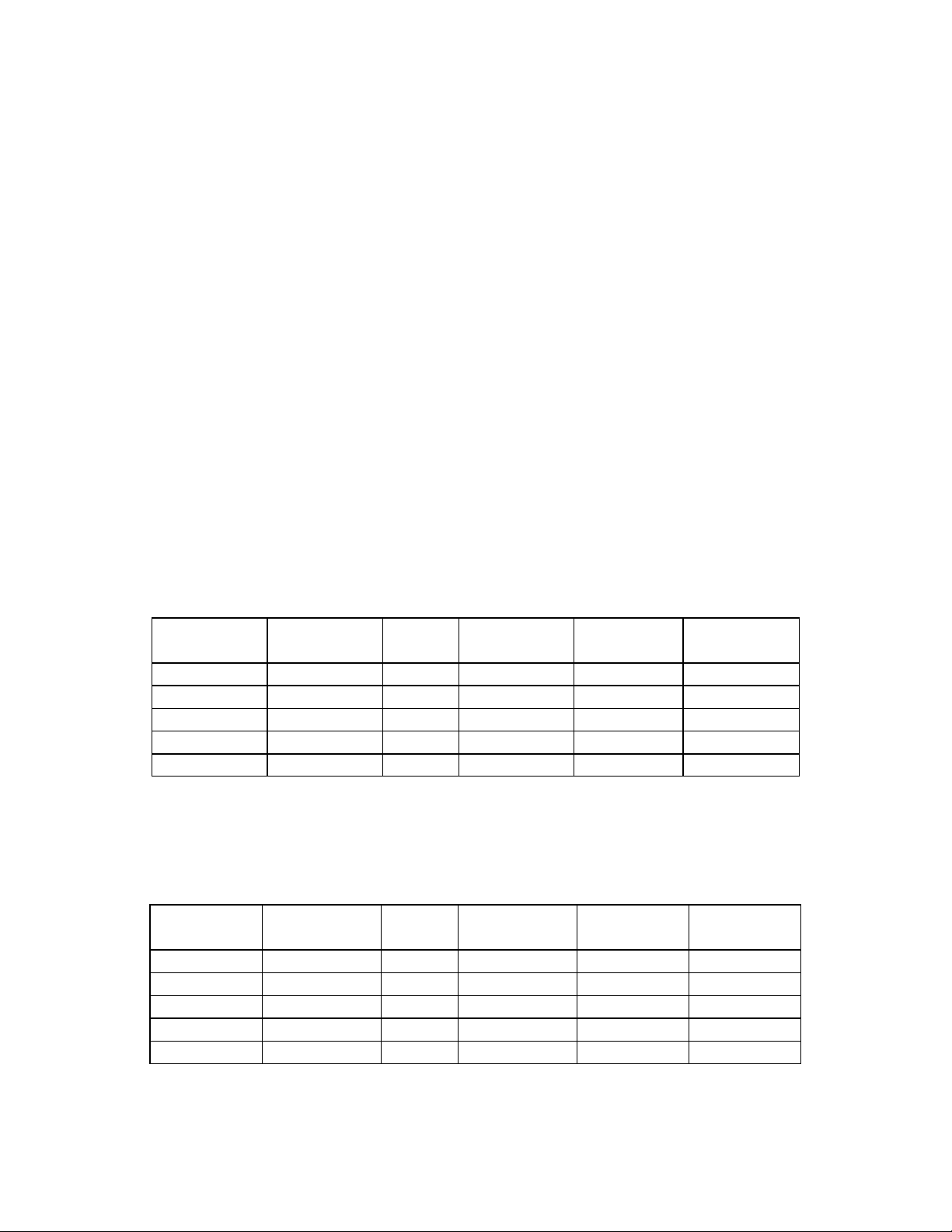
Fuel Temp.
(°C)
140 284 75 40 104 1,150
120 248 111 20 68 2,450
100 212 184 0 32 5,740
80 176 318 -20 -4 15,000
60 140 584 -40 -40 45,770
• The 2 wire engine coolant temperature sensor is located on the thermostat housing
at the right front corner of the engine. The coolant sensor's temperature detection
component uses a thermistor. A 5 volt reference voltage is applied at all times to the
sensor from the ECM. The ECM detects a voltage change due to a resistance value
change in the sensor caused by the coolant temperature change.
Coolant
Temp. (°C)
140 284 76 40 104 1,161
120 248 118 20 68 2,500
100 212 190 0 32 5,773
80 176 325 -20 -4 15,216
60 140 591 -40 -40 47,365
Fuel Temp.
(°F)
Coolant
Temp. (°F)
Ohms
Ω
Ohms Ω Coolant
Fuel Temp.
(°C)
Temp. (°C)
Fuel
Temp. (°F)
Coolant
Temp. (°F)
Ohms Ω
Ohms Ω
4
Page 5

y
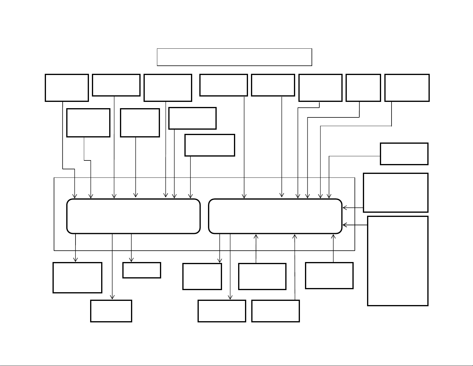
Isuzu 6HK1 Common Rail Engine Fuel System
Common
Rail Fuel PSI
Sensor
Crankshaft
Position
Sensor
Pump PSI
Control Valve
(SCV)
Fuel Temp
Sensor
Camshaft
Position
Sensor
Engine Harness 40 Pin
Connector A1
Coolant
Temperature
Sensor
Engine Control Module
Injectors
EGR DC
Motor
Temp. Sensor
Boost PSI
Sensor
EGR Position
Sensor
Main ECM
Power
Rela
Intake Air
Glow
Relay
Boost Temp
Sensor
Engine Harness 81 Pin
Connector A0
Diagnostic
Switch X24
Data Link
Diag Conn X4
Barometric
AMB PSI
Sensor
Memory Clear
Switch X23
ENG Oil
PSI
Sensor
1 Ignition Wire
2 Positive Wires
6 Ground Wires
(Instrumentation
Engine Stop
Switch
Start Signal
(Fuel Boost)
Power Supply
CAN Data Bus
Connector
Throttle,
Idle Up/Down,
Work Modes,
Breaker Mode,
Tach,
& Faults)
5
Page 6

Isuzu 4HK-1 and 6HK-1 Engine Overview (continued)
Inputs to 40 pin engine harness connector(continued):
• The 2 wire crankshaft position sensor (CKP) is located on the flywheel housing at
the left rear corner of the engine. The CKP sensor detects 45 projections equally
spaced every 7.5° around the flywheel periphery. There is also a space (equal to 3
projections) to act as a top dead center (TDC) reference signal for the engine control
module (ECM). With these 45 pulses and the TDC reference signal, the ECM
calculates the engine speed and exact position of the crankshaft.
• The 2 wire camshaft position sensor (CMP) is located on the cylinder head at the
rear of the camshaft gear. The camshaft position sensor detects a total of the
number of the cylinders in the engine plus an extra one. The extra hole indicates the
top dead center position of number 1 cylinder. Five through holes (four holes
arranged equally every 90° on the gear and one reference hole) on the camshaft
gear flange surface on the 4HK-1 Engine. Seven through holes (six holes arranged
equally every 60° on the gear and one reference hole) on the camshaft gear flange
surface on the 6HK-1 Engine. The camshaft position sensor indicates the rotational
position of the camshaft to the ECM. The CMP signal input, determines the crank
angle and the ECM can use it to control fuel injection and calculate the engine
speed. The crankshaft position sensor (CKP) typically controls these functions,
however it is done by CMP sensor if the CKP sensor is faulty.
Diagnostic aid
If there is relevant Error Code to the crankshaft (CKP) sensor and Camshaft (CMP)
sensor, the engine will not start until memory clear is performed.
If an intermittent trouble is suspected, the following may be the cause:
• Improper connection of harness connector
• Defective harness routing
• Worn harness cover
• Wire disconnection inside harness cover
• The 3 wire boost pressure sensor is located in the piping to the intake manifold of
the engine. The sensor converts the boost pressure into the voltage signal and
sends it to engine control module (ECM). The ECM should detect a higher signal
voltage at a high boost pressure.
• The 4 wire Exhaust Gas Recirculation (EGR) position sensor is installed in EGR
valve and detects the valve lift amount of EGR.
Note:
Do not disassemble the EGR position sensor. If it is faulty, replace it as EGR
valve assembly.
6
Page 7

y
Isuzu 6HK1 Common Rail Engine Fuel System
Common
Rail Fuel PSI
Sensor
Crankshaft
Position
Sensor
Pump PSI
Control Valve
(SCV)
Fuel Temp
Sensor
Camshaft
Position
Sensor
Engine Harness 40 Pin
Connector A1
Coolant
Temperature
Sensor
Engine Control Module
Injectors
EGR DC
Motor
Temp. Sensor
Boost PSI
Sensor
EGR Position
Sensor
Main ECM
Power
Rela
Intake Air
Glow
Relay
Boost Temp
Sensor
Engine Harness 81 Pin
Connector A0
Diagnostic
Switch X24
Data Link
Diag Conn X4
Barometric
AMB PSI
Sensor
Memory Clear
Switch X23
ENG Oil
PSI
Sensor
1 Ignition Wire
2 Positive Wires
6 Ground Wires
(Instrumentation
Engine Stop
Switch
Start Signal
(Fuel Boost)
Power Supply
CAN Data Bus
Connector
Throttle,
Idle Up/Down,
Work Modes,
Breaker Mode,
Tach,
& Faults)
7
Page 8

Isuzu 4HK-1 and 6HK-1 Engine Overview (continued)
Inputs to 81 pin engine harness connector:
• The 2 wire intake air temperature (IAT) sensor is installed on intake air tube and
detects the temperature of intake air for optimum fuel injection control.
• The 2 wire boost temperature sensor is installed onto the EGR valve on the
upstream side of intake manifold. The sensor is a thermistor type. The resistance in
the sensor changes as the temperature changes. When the intake temperature
sensor is cold, the sensor resistance is high. When the intake temperature
increases, the sensor resistance decreases. With high sensor resistance, the ECM
detects a high voltage on the signal circuit. With lower sensor resistance, the ECM
detects a lower voltage on the signal circuit.
• The 3 wire barometric pressure sensor is installed on the machine and converts the
ambient barometric pressure into a voltage signal. The ECM calculates barometric
pressure by this voltage signal and corrects the fuel injection amount (high-altitude
correction) as the machine works at a higher elevation.
• The 3 wire engine oil pressure sensor is located on the left side of the engine just
below and forward of the high pressure injection pump.
• An engine emergency stop signal is sent from the machine controller to the engine
controller. The machine controller receives an engine stop signal from the stop
switch located in the instrument cluster.
• As the engine is started (after the key switch is turned to the START position to start
the engine, and until the return of the key switch to the ON position), optimum fuel
injection quantity is delivered based on information from the starter switch signal,
engine speed, and the engine coolant temperature sensor (ECT). At low
temperature, the fuel injection quantity increases. As the engine starts completely,
this boosted quantity mode at starting is cancelled and normal running mode is
restored.
• Power Supply – Ignition power is sent to the engine control module (ECM) any time
that the key switch is in the run position. When the ignition signal is present, the
ECM activates the main relay. Once the Main Relay (K33 on machine schematic) is
activated, battery power is fed to the ECM through the relay normally open (NO)
contact to pins number 2 and 6. When the key switch is turned to the off position,
the ECM continues to hold the main relay activated for a period of time to allow the
ECM to power down safely. This delay is about 10 seconds. The ECM has six
ground connections in total.
8
Page 9

y
Isuzu 6HK1 Common Rail Engine Fuel System
Common
Rail Fuel PSI
Sensor
Crankshaft
Position
Sensor
Pump PSI
Control Valve
(SCV)
Fuel Temp
Sensor
Camshaft
Position
Sensor
Engine Harness 40 Pin
Connector A1
Coolant
Temperature
Sensor
Engine Control Module
Injectors
EGR DC
Motor
Temp. Sensor
Boost PSI
Sensor
EGR Position
Sensor
Main ECM
Power
Rela
Intake Air
Glow
Relay
Boost Temp
Sensor
Engine Harness 81 Pin
Connector A0
Diagnostic
Switch X24
Data Link
Diag Conn X4
Barometric
AMB PSI
Sensor
Memory Clear
Switch X23
ENG Oil
PSI
Sensor
1 Ignition Wire
2 Positive Wires
6 Ground Wires
(Instrumentation
Engine Stop
Switch
Start Signal
(Fuel Boost)
Power Supply
CAN Data Bus
Connector
Throttle,
Idle Up/Down,
Work Modes,
Breaker Mode,
Tach,
& Faults)
9
Page 10

Isuzu 4HK-1 and 6HK-1 Engine Overview (continued)
Inputs to 81 pin engine harness connector: (continued)
• The CAN (Controller Area Network) Data Bus Connector transmits communication
between the engine controller and the Excavator controller. This connector
transmits throttle, idle up/down, work mode, breaker mode, tachometer,
instrumentation and fault code information.
• The memory clear (X23), diagnostic switch (X24) and data link (X4) connectors are
not used with the Case Electronic Service Tool (EST) diagnostic system. They are
required when using the Tech 2 Diagnostic Tool.
Outputs from 81 pin engine harness connector:
• When the ignition signal is present from the keyswitch, the ECM activates the main
relay. Once the Main Relay (K33 on machine schematic) is activated, battery power
is fed to the ECM through the relay normally open (NO) contacts to pins number 2
and 6. When the key switch is turned to the off position, the ECM continues to hold
the main relay activated for a period of time to allow the ECM to power down safely.
This delay is about 10 seconds.
• The glow control relay system consists of the ECM, glow relay, glow plug. When the
key switch is turned ON with low engine coolant temperatures, the ECM determines
the glow time and operates the glow relay (K2). After a certain time has elapsed, the
ECM will turn the glow relay to “OFF”. Also, after-glow function allows to stabilize
idling immediately after starting.
Outputs from 40 pin engine harness connector:
• The engine driven high pressure injection pump pressurizes fuel to feed to the
common rail. The injection pump has a suction control valve (SCV), and a fuel
temperature (FT) sensor. The suction control valve (SCV) is installed onto high
pressure pump section and controls supply of fuel (discharge amount) to common
rail. The engine control module (ECM) regulates period of electrical activation time of
the SCV to regulate the fuel discharge amount.
Do not replace the SCV. If it is faulty, replace it as supply pump ASM.
• The exhaust gas recirculation (EGR) system recirculates a part of the exhaust gas to
the engine intake to reduce the combustion temperature inside the cylinders to
reduce NOx (nitrogen oxides) in the exhaust gas. The EGR valve opening is
calculated according to the engine coolant temperature (ECT), the engine speed,
and the target fuel injection quantity. The EGR motor is the brushless DC motor,
and is driven by three phases. The ECM drives the EGR motor through the EGR
motor drive circuits U, V, and W. The motor rotates with a combination of the threephase signals. The ECM sets the Error Code when the EGR motor drive duty is
high and the difference between the target EGR position and actual EGR position is
large.
10
Page 11

y
Isuzu 6HK1 Common Rail Engine Fuel System
Common
Rail Fuel PSI
Sensor
Crankshaft
Position
Sensor
Pump PSI
Control Valve
(SCV)
Fuel Temp
Sensor
Camshaft
Position
Sensor
Engine Harness 40 Pin
Connector A1
Coolant
Temperature
Sensor
Engine Control Module
Injectors
EGR DC
Motor
Temp. Sensor
Boost PSI
Sensor
EGR Position
Sensor
Main ECM
Power
Rela
Intake Air
Glow
Relay
Boost Temp
Sensor
Engine Harness 81 Pin
Connector A0
Diagnostic
Switch X24
Data Link
Diag Conn X4
Barometric
AMB PSI
Sensor
Memory Clear
Switch X23
ENG Oil
PSI
Sensor
1 Ignition Wire
2 Positive Wires
6 Ground Wires
(Instrumentation
Engine Stop
Switch
Start Signal
(Fuel Boost)
Power Supply
CAN Data Bus
Connector
Throttle,
Idle Up/Down,
Work Modes,
Breaker Mode,
Tach,
& Faults)
11
Page 12

Isuzu 4HK-1 and 6HK-1 Engine Overview (continued)
Outputs from 40 pin engine harness connector: (continued)
• The injectors are controlled by the engine control module (ECM). The ECM sends a
common power supply to injectors 1, 3 and 5. The ECM also sends a common
power supply to injectors 2, 4 and 6. The ECM fires the injectors by controlling the
ground of the individual injectors. The ECM calculates the basic injection amount
and timing based on the signals from throttle position sensor, boost pressure sensor,
crankshaft (CKP) sensor, camshaft (CMP) sensor, etc. The timing of the injection is
controlled by when the injector activates. The fuel quantity delivered is based upon
the amount of time that the injector is open and also the pressure supplied by the
common rail. To improve combustion in cylinders, the system injects a little fuel (preinjection or pilot injection) and ignites it at the beginning of the cycle. A second
injection (main injection) delivers the fuel required deliver the horsepower needed.
12
Page 13
y
Isuzu 6HK1 Common Rail Engine Fuel System
Common
Rail Fuel PSI
Sensor
Crankshaft
Position
Sensor
Pump PSI
Control Valve
(SCV)
Fuel Temp
Sensor
Camshaft
Position
Sensor
Engine Harness 40 Pin
Connector A1
Coolant
Temperature
Sensor
Engine Control Module
Injectors
EGR DC
Motor
Temp. Sensor
Boost PSI
Sensor
EGR Position
Sensor
Main ECM
Power
Rela
Intake Air
Glow
Relay
Boost Temp
Sensor
Engine Harness 81 Pin
Connector A0
Diagnostic
Switch X24
Data Link
Diag Conn X4
Barometric
AMB PSI
Sensor
Memory Clear
Switch X23
ENG Oil
PSI
Sensor
1 Ignition Wire
2 Positive Wires
6 Ground Wires
(Instrumentation
Engine Stop
Switch
Start Signal
(Fuel Boost)
Power Supply
CAN Data Bus
Connector
Throttle,
Idle Up/Down,
Work Modes,
Breaker Mode,
Tach,
& Faults)
13
Page 14
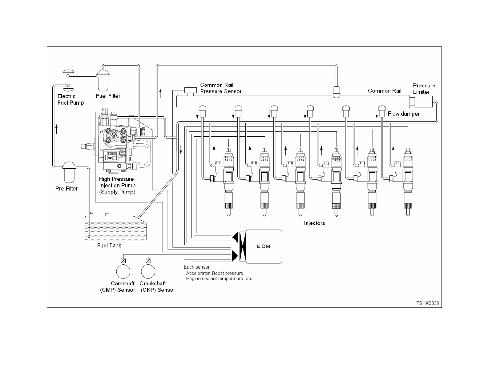
Isuzu 4HK-1 and 6HK-1 Engine Fuel Schematic Overview
Fuel System Hydraulic Function
Fuel comes from the tank and typically will go through a prefilter assembly. From the
prefilter, the fuel then flows to an electric fuel pump, located in the hydraulic pump
compartment. The 24 volt electric fuel pump is powered directly by the battery relay,
through the 65 amp fuse (F23) and the 10 amp electrical fuel pump fuse (F8) in the fuse
box. The electric fuel pump then sends the fuel through the fuel filter also located
hydraulic pump compartment to the inlet port of the high pressure injection pump.
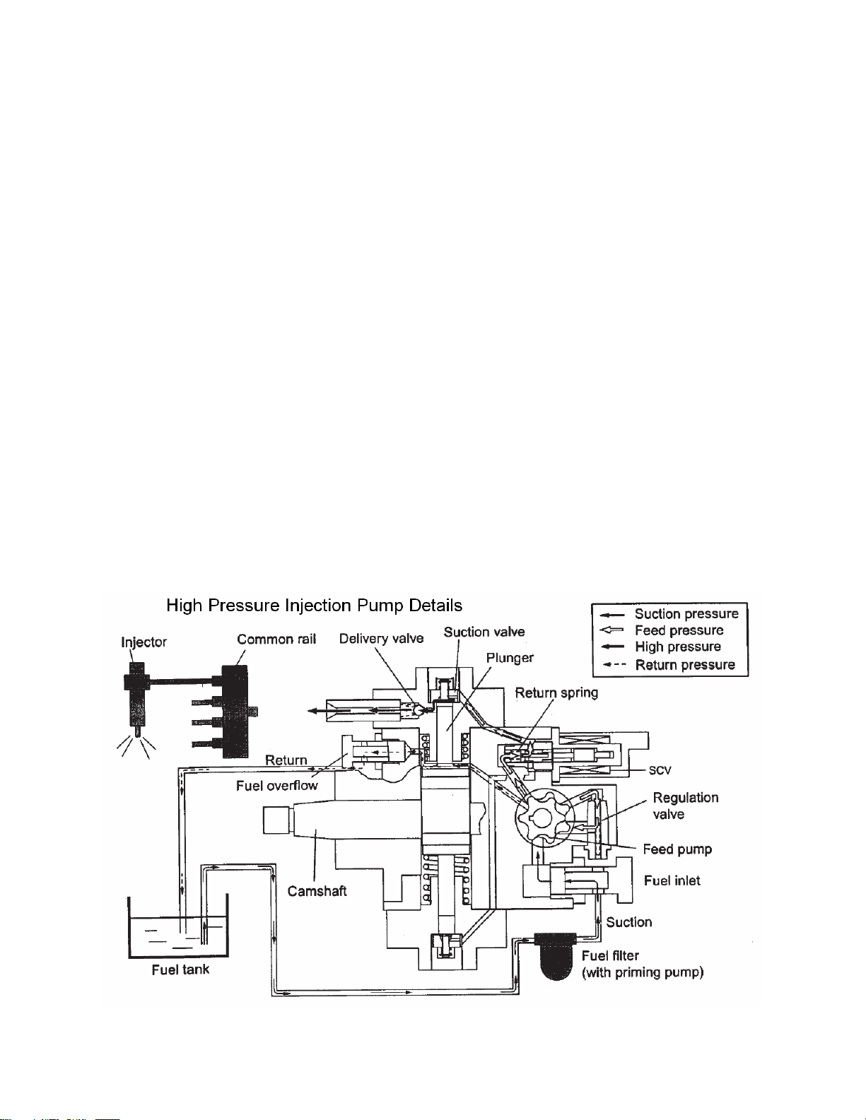
The high pressure injection pump is mounted at the left rear of the engine. This pump
needs to be timed to the engine. To install the pump, bring the engine to TDC and then
align the mark on the pump drive gear to the mark on the front face of the high pressure
pump. Once these conditions are met, install the injection pump. The high pressure
injection pump has a shaft driven gerotor feed (charge) pump which provides fuel to the
pump pressure control valve (Suction Control Valve SCV). The gerotor pump outlet
pressure is controlled by the regulation valve to provide a constant pressure at the inlet
of the high pressure pumping pistons. The high pressurepump PSI regulator (SCV),
located in the injection pump, controls the flow output of the high pressure pump. The
high pressure pump supplies the quantity of fuel to the common rail required to maintain
the pressure dictated by the engine control unit (ECM). This assures that only the
required amount of fuel is pressurized, improving energy efficiency and limiting heating
of fuel in the system. The common rail pressure will range from 3625 to 29,000 PSI (25
to 200 MPa). Excess flow from the feed pump and internal leakage from the injection
pump returns to the tank. The fuel temperature sensor (FT) monitors the temperature of
this fuel.
14
Page 15
15
Page 16

Isuzu 4HK-1 and 6HK-1 Engine Fuel Schematic Overview
The common rail system stores high pressure fuel between the supply pump and the
injectors. The common rail also serves as an accumulator to dampen the fuel
pulsations from the pump. Flow dampers are located at the outlet of the common rail to
the lines to the injectors. They minimize the pulsation of fuel pressure inside the
common rail. The flow dampers also cut off the fuel flow in case an injection line or
injector leaks. An orifice in the flow damper piston supplies the fuel to the injectors. An
orifice in a spring loaded damper piston acts as a pulsation damper. In the event that
there is excessive flow through the orifice, the leading end of the piston closes off the
fuel supply to the injection pipe or injectors. The piston again allows fuel flow when the
fuel pressure inside the common rail becomes about 0.6 MPa (87 psi).
High pressure fuel from the common rail is available to the inlet of all of the injectors. A
high pressure line connects the common rail to each injector. The high pressure supply
tube is to be replaced each time it is removed. Each injector has a solenoid valve
which, when triggered, causes the injection of a high pressure fuel mist into the
combustion chamber. This injection can happen more that once during each firing cycle
to control emissions and also make the engine run quieter.
When each injector fires a small amount of drain flow is generated. The injector drain
flow collects into a common drain tube which returns to the fuel tank.
A safety relief valve, located at the rear of the common rail, limits the maximum
pressure to a maximum of approximately 33,350 PSI (230 Mpa). This can happen if the
flow control solenoid valve (SCV) becomes defective. The common rail pressure
sensor is located at the bottom of the common rail.
16
Page 17

17
Page 18

18
Page 19

Isuzu 4HK-1 and 6HK-1 Engine Sensor Locations
19
Page 20

Exhaust gas Recirculation (EGR) System
Exhaust Gas Recirculation system is abbreviated to EGR system. It recirculates part of
exhaust gas into intake manifold to mix an inert gas with intake air. This leads to lower
the combustion temperature to limit emissions of nitrogen oxide (NOx).
It controls amount of EGR by opening/closing the EGR valve installed between exhaust
manifold and intake manifold. It determines amount of EGR, based on the engine
speed and load rate on engine (fuel injection amount), and operates the EGR valve to
control the amount of EGR.
The cooling system (EGR cooler) equipped on the EGR gas passage allows to cool
down high temperature EGR gas and mix it with new air to lower the combustion
temperature further, resulting in limiting NOx effectively (Cooled EGR).
On the 4HK1 and 6HK1-TC model engines, the EGR system has the check valve to
stop backward flow of EGR gas and flows it in one direction only.
The engine control module (ECM) operates the EGR motor according to engine speed,
engine load, etc. to control amount of EGR valve lift. The amount of valve lift is
detected by EGR position sensor. The dark color area in the figure shows that the valve
lift amount is large, and the darkest color area shows that the valve lift amount is almost
100%.
20
Page 21

21
Page 22

22
Page 23

Installation of ECM
Install the ECM in the reverse order of removal.
EGR valve position learning is required after replacing
the ECM.
1. Turn the key switch to “ON”.
2. Turn the key switch to “OFF”.
3. Leave as it is, "OFF", for 10 seconds.
Failure to perform the EGR valve position learning may
result in detection of Error Code for EGR.
About ECM power off
The power supply inside the ECM does not go off for
about 10 seconds after turning the key switch OFF. If
the ECM power needs to be off such as for memory
clear, wait for more than 10 seconds after turning the
key switch OFF.
Engine Control System 42
Key switch
ON
Key switch
OFF
10 sec
TSWG0176
Page 24

Senser and actuator
Engine Control System 56
*Refer at last page.(About wiring diagrams)
Page 25

57 Engine Control System
Circuit diagram
(Refer to “Wiring diagrams” for a way to read the diagram.)
Main relay circuit
Engine control module (ECM)
(20A)*
FUSE B
20A
()*
Main relayBattery
40 21 E-57 E-57 E-57 E-57
B+ B+
52
TSWG0027
Page 26

Starter for safety relay, glow circuit
Engine Control System 58
Engine control
module (ECM)
Starter
B
Safety relay
S
C
Generator
L
B
(65A)*
Battery
C
B
(30A)*
E
Glow relay
control
10 E-57
R
Glow
plug
Glow
relay
5
B/W
1 H-22
1 H-1
TSWG0068
Page 27

59 Engine Control System
CAN, GND, DLC circuits
Engine control
module (ECM)
Shovel
controller
CAN HIGHCAN LOW
18 E-57
37 E-574 E-573 E-571 E-5743 E-5762 E-5781 E-57
CAN HIGH CAN LOW
38 E-57
KWP2000
52 E-57
7 FL-150
1 FL-150
DLC
4 FL-1505 FL-150
TSHK0013
Page 28

Injector circuit
Injector
E-31
12
Injector
E-27
21
Injector
E-29
21
(Cylinder No. 3)
3
(Cylinder No. 1)
3
(Cylinder No. 2)
3
E-31
E-27
E-29
4 H-94
6 H-94
2 H-94
7 H-94
4 H-94
6 H-94
2 H-94
7 H-94
1.25
W
0.75
L/W
0.75
L
0.75
G/R
Engine Control System 60
Feedback
Cylinder No. 3
5
8
12
117 E-56
E-56
119
114 E-56
Cylinder No. 1
Feedback
Cylinder No. 2
Feedback
Engine control module (ECM)
Injector
E-33
21
Injector
E-37
21
Injector
E-35
21
(Cylinder No. 4)
(Cylinder No. 6)
(Cylinder No. 5)
3 E-33
3 E-37
E-35
3
3 H-94
4 H-95
2 H-95
6 H-95
7 H-95
3 H-94
4 H-95
2 H-95
6 H-95
7 H-95
1.25
W
1.25
R
0.75
G/B
0.75
L/R
0.75
L/Y
H-12 H-12 H-12 H-12
4
H-12
11
7
6
121 E-56
115 E-56
E-56
118
120 E-56
B+
Feedback
Cylinder No. 4
Feedback
Cylinder No. 6
Feedback
Cylinder No. 5
3 H-95
3 H-95
1.25
R
H-12 H-12 H-12
3
116 E-56
B+
TSWG0031
Page 29

61 Engine Control System
SCV circuit
E-161
2
SCV
E-161
1
0.75
0.75
R/W
R/B
23 H-6H-6
Engine contorol
module (ECM)
97 E-56 89 E-56 105 E-56 113 E-56
B+
TSHK0016
Page 30

Engine Control System 62
CKP sensor, fuel temperature sensor, engine coolant temperature sensor, engine oil pressure sensor circuit
0.75
W/B
5V
Vcc
sensor signal
Engine oil pressure
80 E-56
67 E-56
79 E-56
H-20
9
10
H-20 H-20
11
0.75
0.75
L/Y
B/Y
0.75
B/Y
3
2
E-76 E-76 E-76
1
Engine
coolant
Engine oil
pressure sensor
temperature
sensor
Engine control
module (ECM)
CAN HIGHCAN LOW
A
37 E-57 18 E-57
Shovel
controller
Monitor
CAN HIGH CAN LOW
5V
5V
Engine coolant
temperature sensor
signal
84 E-56
Fuel temperature
sensor signal
83 E-56
CKP
LOW
signal
CKP
signal
HIGH
107 E-56 106 E-56
H-20
7
H-6
1
H-20
H-20
21
0.75
0.75
0.75
R/B
B/Y
Y/G
0.75
0.75
W/L
B/R
2 E-90
1 E-93 1 E-90
2 E-93
Fuel temperature sensor
CKP sensor
2 E-98 1 E-98
E-56
108
H-20
3
0.75 Br
TSHK0017
Page 31

63 Engine Control System
Boost temperature sensor, boost pressure sensor circuit
Engine control
module (ECM)
5V
sensor signal
Boost pressure
5V
Boost temperature
sensor signal
95E-56109
91 E-56 E-56
74 E-56
H-20
8
H-20
16
H-20
17
H-20
15
0.75
0.75
0.75
0.75
0.75
R/W
L
R/L
R/L
B/R
E-75
3
E-75
2
E-75
1
E-163E-163
1
2
Boost pressure sensor
Boost temperature sensor
TSWG0034
Page 32

CMP sensor, common rail pressure sensor, EGR circuit
Engine control
module (ECM)
0.75
Engine Control System 64
B
5 E-80
EGR position
sensor signal
EGR position
sensor signal
EGR position
sensor signal
5V
B+
111 E-56
94 E-56
B+
103 E-56
93 E-56
B+
110 E-56
92 E-56
87 E-56
5
1
6
H-8 H-8 H-8 H-8
2
H-8
7
H-8
3
H-20
12
0.75
0.75
0.75
0.75
0.75
0.75
0.75
W/R
G/B
W/B
G/W
W/L
G/Y
W
E-80
8
E-80
4
E-80
7
E-80
3
E-80
6
E-80
2
E-80
1
0.75
U
W
V
W
E-113
3
EGR valve
EGR position sensor/EGR motor
sensor signal
Common rail pressure
signal
CMP sensor
90 E-56
82 E-56100 E-56
101 E-56
98 E-56
99 E-56
H-20
13
H-20
14
6
5
H-20 H-20 H-20
4
0.75
0.75
0.75
Br
B/W
W/R
0.75
0.75
0.75
G
B
Br
E-113
2
Common rail pressure sensor
E-113
1
3 E-112
E-112
2
E-112
1
CMP sensor
TSHK0018
Page 33

65 Engine Control System
Memory clear switch, engine stop switch circuit
control module
(ECM)
CAN HIGHCAN LOW
37 E-57 18 E-57
47 E-57
32 E-5752 E-57
CN-6
CAN LOW
43 CN-3
CAN HIGH
2I
TSWG0038
Page 34

This page Is Intentionally Left Blank.
Page 35

67 Engine Control System
R
1.25
324
786
R
L/YL/R
1.25
0.75
G/B
0.75
0.75
1
H95
5
INJECTOR 2(#4.5.6 )
34
2
678
0.75 0.75 0.75
1
5
L G/Y G/W G/B
0.75
W/RW/BW/LL/W
E80
0.75 0.75 0.75 0.75
EGR VALVE
E93
SENSOR:FUEL TEMP
12
R/W R/B
0.75 0.75
E161
SCV
23
0.5 0.5
1
B/W V/W Y
0.75
E112
SENSOR:CAM ANGLE(G)
W
1.25
3
W
1.25
24
L
H94
0.75
1
INJECTOR 1(#1.2.3 )
78
G/RL/W
0.75
6
0.75
5
123
0.75 0.75 0.75
12
R/L L R/W
0.75 0.75
B/Y Y/G
E75
12
R/L B/R
0.75 0.75
SENSOR:BOOST PRESS
E163
SENSOR:MAT(BOOST TEMP)
1
0.75
E164
SWITCH:O/H
E98
12
Y V /W
0.5 0.5
SENSOR:NE.CRANK
1
9101112
1
2
3
4
0.75 0.75 0.50.75
1.251.25
L/Y B/Y LW/B
5
B/W
H22
B/R LL/WBr
H20
0.5 0.75 0.750.5
13 14 15 16
17 18 19 20
R/L
0.75
L/Y L/WL/RL
0.75 0.75
0.750.75
0.75 0.75 0.75
G/Y G/W G/B
G/BG/R
0.750.75
12 11 10 9
W/R
0.75
65
0.75
W/B
7
W/L
0.75
8
H12
H8
76 5
RW
8
1
2
3
4
E76
123
B/Y L/Y W/B
0.75 0.75 0.75
4
Y
SENSOR:OIL PRESSRE
G
0.5
3
R/B R/WB/WV/W
0.75 0.75
2
67 8
0.5 0.750.5
V/WYB
0.750.5
1
5
5
1
B/W
H1
GLOW PLUG
3
12
B/Y R/B
0.75 0.75
0.75
1
R
0.75
2
54
H6
0.75 0.75
3
6
G
Y/G R/W R/B
0.75
23
0.5 0.5
E113
1
0.5
R
E90
L/W Br L
SENSOR:COM(PC)
0.75
SENSOR:WATER
TSHK0035
Page 36

Engine Control System 68
E75
Terminal
Number
1 Boost pressure sensor GND
2 Boost pressure sensor Vout
3 Boost pressure sensor Vcc
E76
Terminal
Number
1 Engine oil pressure sensor GND
2 Engine oil pressure sensor Vout
3 Engine oil pressure sensor Vcc
E80
Terminal
Number
1EGR Vcc
E98
Terminal
Number
1 CKP +
2 CKP GND
E112
Terminal
Number
1 CMP shield
2CMP GND
3CMP +
E113
Terminal
Number
1 Common rail pressure sensor GND
2 Common rail pressure sensor Vout
2 EGR hall sensor W
3 EGR hall sensor V
4 EGR hall sensor U
5 EGR GND
6 EGR motor W
7 EGR motor V
8 EGR motor U
E90
Terminal
Number
1ECT GND
2ECT +
3ECT meter
E93
Terminal
Number
3 Common rail pressure sensor Vcc
E161
Terminal
Number
1SCV — Hi
2SCV — Lo
E163
Terminal
Number
1 Boost temperature sensor GND
2 Boost temperature sensor +
E164
Terminal
Number
1 Overheating switch
1 Fuel temperature sensor GND
2 Fuel temperature sensor +
H1
Terminal
Number
1Glow
Page 37

69 Engine Control System
H6
Terminal
Number
1SCV−Lo
2SCV−Hi
3 Fuel temperature sensor +
4ECT meter
5—
6 Overheating switch
H8
Terminal
Number
1 EGR hall sensor U
2 EGR hall sensor V
3 EGR hall sensor W
4—
5 EGR motor U
6 EGR motor V
7 EGR motor W
8—
H20
Terminal
Number
1 CKP +
2 CKP GND
3 CKP shield
4CMP +
5CMP GND
6 CMP shield
7ECT +
8 Boost pressure sensor Vcc
9 Engine oil pressure sensor Vcc
10 Engine oil pressure sensor Vout
11 Engine oil pressure sensor GND
12 Common rail pressure sensor Vcc
13 Common rail pressure sensor Vout
14 Common rail pressure sensor GND
15 Boost temperature sensor +
16 Boost pressure sensor Vout
17 Boost pressure sensor GND
18 —
H12
Terminal
Number
1—
2—
3 Injector power supply 2
4 Injector power supply 1
5 OS — INJ3 signal
6 OS — INJ2 signal
7 OS — INJ4 signal
8 OS — INJ1 signal
9—
10 —
11 OS — INJ6 signal
12 OS — INJ5 signal
19 —
20 —
H22
Terminal
Number
1Glow
H94
Terminal
Number
1—
2 OS — INJ1 signal
3 Injector power supply 1
4 Injector power supply 2
5—
6OS−INJ3 signal
7OS−INJ5 signal
8—
Page 38

H95
Terminal
Number
1—
2OS−INJ6 signal
3 Injector power supply 2
4 Injector power supply 1
5—
6OS−INJ4 signal
7OS−INJ2 signal
8—
Engine Control System 70
H94
(Female connector
on injector side)
H95
(Male connector on ECM side)
H94
(Male connector on ECM side)
H95
(Female connector on injector side)
In cylinder head
TSWG0041
Page 39

71 Engine Control System
Connector list
No. Connector Face
E-27
#1 injector (Silver)
E-29
#2 injector (Silver)
E-31
#3 injector (Silver)
No. Connector Face
E-75
E-76
123
123
(Black)
E-80
(Black)
003-501
003-501
E-33
E-35
E-37
E-56
#4 injector (Silver)
#5 injector (Silver)
#6 injector (Silver)
E-90
E-93
E-98
E-112
1 2
3
003-500
(Blue)
(Gray)
(Black)
E-57
(Gray)
(Gray)
(Black)
E-113
(Gray)
Page 40

Engine Control System 72
No. Connector Face
E-114
(Black)
E-161
(Brown)
E-162
(Dark gray)
No. Connector Face
H1
(Black)
H-6
(Gray)
H-6
(Gray)
E-163
E-164
FB-124
FL-150
(Gray)
(Black)
H-8
(Black)
H-8
(Black)
H-12
(Gray)
87654321
161514131211109
016-500
H-12
(Gray)
FL-269
1 2 3
1 2 3 4
5 6 7 8
H-20
003-502
9 10 11 12
13 14 15 16
17 18 19 20
020-500
Page 41

73 Engine Control System
No. Connector Face
4 3 2 1
8 7 6 5
H-20
12 11 10 9
16 15 14 13
20 19 18 17
H22
(White)
H22
(White)
No. Connector Face
H-95
(ECM
side)
020-501
(Gray)
H-95
(Injector
side)
(Gray)
H-95
(Injector
side)
(Gray)
H-94
(ECM
side)
H-94
(ECM
side)
H-94
(Injector
side)
H-94
(Injector
side)
(Gray)
(Gray)
(Gray)
H-95
(ECM
side)
(Gray)
(Gray)
Page 42

This page Is Intentionally Left Blank.
Page 43

103 Trouble Shooting - EXAMPLE From Service Manual
Error Code: 0088
Common rail pressure is abnormally high (1st or 2nd stage).
2
3
6
5
4
7
Name
1. Common rail
2. Fuel filter
3. Electromagnetic Pump
4. Pre-filter
TSHK0041
5. Fuel tank
6. Supply pump
7. Injector
Page 44

Trouble Shooting 104
Engine control
module (ECM)
CMP sensor
signal
99 E-56
98 E-56
H-20 H-20 H-20
0.75
0.75
B/W
W/R
14E-112
25E-112
6
0.75
Br
3 E-112
0.75
Br
Common rail pressure
101 E-56
H-20
14
0.75
B
1
E-113
sensor signal
82 E-56100 E-56
90 E-56
13
H-20
0.75
G
2
E-113
5V
87 E-56
0.75
W
3
E-113
EGR position
sensor signal
H-20
0.75
W
112E-80
92 E-56
H-8
0.75
G/Y
23E-80
B+
110 E-56
H-8
0.75
W/L
67E-80
EGR position
sensor signal
93 E-56
H-8 H-8 H-8 H-8
0.75
G/W
32E-80
103 E-56
76E-80
W
V
EGR position
sensor signal
B+
94 E-56
0.75
W/B
41E-80
U
0.75
G/B
B+
111 E-56
0.75
W/R
85E-80
0.75
B
5 E-80
CMP sensor
Common rail pressure sensor
Description of circuit
The common rail pressure sensor detects the common
rail internal pressure. The common rail pressure sensor
is installed to the common rail. As the common rail
internal pressure changes depending on engine
condition, output voltage of the common rail pressure
sensor will change (if the common rail internal fuel
pressure is low, output voltage becomes low, if the
pressure is high, the output voltage becomes high as
well). The engine control module (ECM) reads this
output voltage change, converting it into common rail
internal pressure, to utilize for control. Dedicated
communication circuits are used for the sensor power
supply (5V), SIG, and ground in the common rail
pressure sensor, which are connected to the ECM.
Also, the sensor circuit is shielded to avoid electrical
noise etc.
Main trouble symptom
• Intense engine vibration
EGR position sensor/EGR motor
EGR valve
TSHK0028
• Rough idling
• Output lowering
• Engine blow up fault
• Black smoke emitted
• Excessive output possible
Preconditions when Error Code is set
1st step
• Key switch input voltage is 18V or more.
• Error Code 0088, 0192, 0193, or 1635 is not
detected.
• Actual rail pressure is 2 MPa or more, and 70 rpm
or more.
2nd step
• Battery voltage is normal.
• Error Code 0088, 0192, 0193, or 1635 is not
detected.
• Actual rail pressure is 2 MPa or more, and 70 rpm
or more.
Page 45

105 Trouble Shooting - EXAMPLE From Service Manual
Error Code set condition
1st step
• Rail pressure is more than 185MPa for 5 seconds
or more.
• Common rail pressure sensor voltage is 3.9 V or
more.
2nd step
• 1st stage is completed, and rail pressure is more
than 190MPa for 5 seconds or more.
• Common rail pressure sensor voltage is 4.0 V or
more.
T>1sec=P1095
T
TSHK0043
200 MPa
190 MPa
185 MPa
Common rail
presure
T
T>5sec=P0088
Action taken when Error Code is set
• "ELEC. PROBLEM" is displayed.
Back-up mode
• L mode fixed.
• Limited injection amount 3 (multi-injection stopped)
• Target RP upper limit (80MPa)
Recovery from failure
• Recovery pattern 1.
Refer to “List of diagnostic trouble code” and “About
recovery from failure” error.
The conditions to clear the Error Code
• The error code is cleared from the current trouble
when the condition is either repaired or
disappeared.
Refer to "About recovery from failure".
Diagnostic aid
If the intermittent trouble is suspected, followings may
be the cause.
• Improper connection of harness connector
• Defective harness routing
• Worn harness cladding
• Wire disconnection inside harness cladding
Following inspections are necessary to detect these
causes.
• Improper connection of harness connector and
ECM connector
– Poor connection of terminal from connector
– Unmatched terminals are fitted.
– Damage of connector lock
– Poor contact between terminal and wire
• Damaged harness
– Visually check the harness for damage.
– Check the relevant items while moving the
connector and the harness which are related to
the sensor.
Step Action Value YES NO
1 Check the error code 0088. — Go to Step 2. —
1. Start the engine.
2. Check the Error Code.
3. Are the fuel-related parts only just
replaced?
2
Air bleeding may not be performed
sufficiently after replacing fuel-related
—
parts. Bleed air again. Check the Error
Code after bleeding air.
Is any of the 0088, 0192, 0193, or 1635
detected?
Go to the relevant
Error Code
detected. Go to Step 3.
Page 46

Trouble Shooting 106
Step Action Value YES NO
1. Check the fuel return pipe between the
supply pump and the fuel tank for
breakage, twist, etc.
2. Check for clogging or twisting in the vent
hose of the fuel tank.
3
3. Check for foreign matter in the fuel tank.
4. If the trouble is detected, repair as
required.
5. Enforce the diagnostic aid.
—
Is the trouble detected?
1. Replace the common rail (common rail
pressure sensor) since it seems that
abnormal value of the pressure sensor is
detected.
Note:
4
For work procedure, refer to “Engine
section” in the service manual.
2. Check the Error Code.
Is the trouble detected?
Replace the supply pump.
Note:
For work procedure, refer to “Engine
5
section” in the service manual.
Is the procedure completed?
Check the Error Code again.
1. Connect all the harnesses.
2. Clear the Error Code.
Refer to “How to clear diagnosis trouble
code (Error Code)” of “Procedure of
trouble diagnosis” in this section for how to
6
clear Error Codes.
3. Turn the key switch to “OFF” for more than
10 seconds.
4. Test run with the “Preconditions when
Error Code is set”.
5. Check the Error Code.
Go to Step 6. Go to Step 4.
—
Go to Step 5. Go to Step 6.
—
Go to Step 6. —
—
Is Error Code 0088 detected?
Check if other Error Code is detected.
7
Is other Error Code detected?
—
Go to Step 2. Go to Step 7.
Go to each Error
Code diagnosis. Verify repair.
Page 47

107 Trouble Shooting - EXAMPLE From Service Manual
About common rail pressure sensor
3
12
TSWG0055
Name
1. Sensor ground
2. Sensor signal
3. Sensor power supply
Characteristics of common rail pressure sensor
(V)
4.2
1
0
200
(MPa)
TSWG0201
Page 48

Connecting the EST
Select the programming/diagnostic
cables to connect:
1. Electronic Service Tool Computer
2. 380002727 EMPS/EST Protocol
Adapter Box
3. Power Supply
• 380002724 AC Adapter Cable
use port DC IN2
• 380002725 Battery Adapter Cable
use port DC IN1
4. ECM located under HVAC cover
behind seat.
5. 380002726 EMPS/EST ECM Cable
6. 380002728 EMPS/EST RS232 Null
Modem Cable
The Additional Tools screen provides a
button linking the Electronic Service
Tool to:
• Engine Diagnostic Tool - Isuzu EMPS
EMPS
The EMPS program is used to
perform the following ECM service
procedures:
• ECM Reflash
• Injector Replacement
• Replace ECM (same model)
• Factory Setting
1. The EMPS application is operated
from its location on the Electronic
Service Tool hard disk drive.
6-xxxxx Copyright © 2006 CNH America LLC All Rights Reserved
Preliminary ELECTRONIC SERVICE TOOL (EST)
1
2
3
4
6
5
1
Engine Module Programming System (EMPS) - Summary
Start the Engine Download Tool - Isuzu EMPS
DC IN1
DC IN2
ECM
DATA
POWER
SELECT
READ ON
READYPOWER
WRITE
OFF
RS-232C ECM
POWER
FUSE
O
N
O
F
F
Page 49

Clearing the ECM Memory
The engine will not operate properly
unless the ECM memory is cleared.
• Install the vehicle ECM harnesses
and then clear the ECM memory.
6-xxxxx Copyright © 2006 CNH America LLC All Rights Reserved
Selecting the Manufacturer
Select SUMITOMO as the
manufacturer for all CNH applications.
Preliminary ELECTRONIC SERVICE TOOL (EST)
Engine Module Programming System (EMPS) - Summary
Process Menu
Selecting an EMPS Process
Select an EMPS operation from the
Process Menu.
• ECM Reflash - Select when the ECM
control program is suspected to have
damaged/corrupted files. This
selection reinstalls the same
operating software files on the ECM
as determined by current Serial
Number listed on the ECM.
Injector Replacement - Select when
•
an injector(s) is/are replaced. This
operation provides injector QR Code
information to the ECM to optimize
engine fuel system performance. Refer
to diagram for injector QR Code
locations.
• Replace ECM (same model) - Select
when the ECM is replaced.
•
Factory Setting - Select when the
ECM control program is suspected to
have damaged/corrupted files.
Restores ECM to the factory settings
as determined by a specific Serial
Number.
EMP
Process Menu
ECM Reflash
Injector Replacement
Replace ECM (same model)
Factory Setting
1
23
EngNo XXXXXX XXXX XXX
#1 55 00 00 B8 A3 D7 C9 B9 BB E7 A1 D4
#2 55 00 00 B8 A3 D7 C9 B9 BB E7 A1 D4
#3 55 00 00 B8 A3 D7 C9 B9 BB E7 A1 D4
#4 55 00 00 B8 A3 D7 C9 B9 BB E7 A1 D4
#5 55 00 00 B8 A3 D7 C9 B9 BB E7 A1 D4
#6 55 00 00 B8 A3 D7 C9 B9 BB E7 A1 D4
1 : Engine Serial Number
2 : Engine Model
3 : QR Code
Factory installed injector QR codes are shown
on the head cover label.
NextExit
Individual injector QR codes are
shown on the top of each injector.
EMPS (Flash Tool)
EMPS
Select the machine’s manufacturer and click OK.
SUMITOMO
OK
EMPS
Clearing Memory
Clearing ECM Memory
Perform the following steps to clear memory if Vehicle (Construction
equipment/machine) is equipped with ECM. The engine will not operate properly
unless memory is cleared.
(1)
Turn the ignition key to ON.
(2)
Turn the Diag SW to ON.
(3)
Turn the Memory Clear SW to ON.
(4)
Wait 5 seconds.
(5)
Turn the Memory Clear SW to OFF.
(6)
Turn the Diag SW to OFF.
(7)
Turn the ignition key to OFF.
(8)
Wait 10 seconds. (Do not trun the ignition key to ON.)
(9)
Turn the ignition key to ON.
(10)
Turn the Diag SW to ON.
(11)
Check the engine.
* If the vehicle etc. is not equipped with ECM, install the ECM on the vehicle and
clear the ECM memory.
Clearing Memory is Completed
Page 50

This page Is Intentionally Left Blank.
 Loading...