

Page 1

WORKSHOP MANUAL
727 (N SERIES)
ENGINE CONTROL SYSTEM
(4HK1 ENGINE)
SECTION 1A
International Service & Parts
Tokyo, Japan
Page 2

N O T I C E
Before using this Workshop Manual to assist you in performing
vehicle service and maintenance operations, it is recommended
that you carefully read and thoroughly understand the information
contained in Section - 0A under the headings “GENERAL REPAIR
INSTRUCTIONS” and “HOW TO USE THIS MANUAL”.
All material contained in this Manual is based on the latest product
information available at the time of publication.
All rights are reserved to make changes at any time without prior
notice.
Page 3

Engine Control System 1A-1
ENGINE
Engine Control System
CONTENTS
Engine Control System . . . . . . . . . . . . . . . . . . . . 1A-2
Precautions on Service . . . . . . . . . . . . . . . . . . . 1A-2
Function and Operation. . . . . . . . . . . . . . . . . . . 1A-4
Component Layout . . . . . . . . . . . . . . . . . . . . . 1A-20
Circuit diagram . . . . . . . . . . . . . . . . . . . . . . . . 1A-25
Strategy-Based Diagnostics . . . . . . . . . . . . . . 1A-31
Functional Check List . . . . . . . . . . . . . . . . . . . 1A-37
Hearing Diagnostic . . . . . . . . . . . . . . . . . . . . . 1A-37
On-Board Diagnostic (OBD) System Check . . 1A-39
Inactive CHECK ENGINE Lamp (MIL) . . . . . . 1A-41
CHECK ENGINE Lamp (MIL) Remains Active 1A-44
Engine Cranks But Will Not Run. . . . . . . . . . . 1A-46
Diagnosis with Tech 2 Scan Tool. . . . . . . . . . . 1A-48
Diagnostic Chart . . . . . . . . . . . . . . . . . . . . . . . 1A-67
DTC11 - No Signal CKP Sensor . . . . . . . . . . . 1A-73
DTC13 - TCV Fault . . . . . . . . . . . . . . . . . . . . . 1A-75
DTC14 - Pump ROM Fault . . . . . . . . . . . . . . . 1A-78
DTC15 - Pump Cam Sensor (NE Sensor)
Short Break Fault . . . . . . . . . . . . . . . . . . . . . . 1A-80
DTC16 - No Signal from Pump Cam Sensor
(NE Sensor) . . . . . . . . . . . . . . . . . . . . . . . . . . 1A-82
DTC21 - ECT Sensor Fault. . . . . . . . . . . . . . . 1A-84
DCT23 - IAT Sensor Fault. . . . . . . . . . . . . . . . 1A-88
DTC24 - AP Sensor Output Fault . . . . . . . . . . 1A-91
DTC25 - VS Sensor Circuit Fault . . . . . . . . . . 1A-95
DTC31 - Idle Up Volume Fault . . . . . . . . . . . . 1A-98
DTC32 - MAP Sensor Fault . . . . . . . . . . . . . 1A-101
DTC34 - Exhaust Brake Open Wiring Fault . 1A-104
DTC35 - Neutral Switch Signal Fault . . . . . . 1A-106
DTC36 - Clutch Switch Signal Fault
(M/T Vehicle only) . . . . . . . . . . . . . . . . . . . . . 1A-108
DTC41 - FT Sensor Cir cuit High Voltage . . . 1A-110
DTC51 - Atmospheric Pressure Sensor Fault 1A-113
DTC52 - ECM Internal Fault . . . . . . . . . . . . . 1A-114
DTC53 - Engine Driver Unit Fault . . . . . . . . . 1A-116
DTC55 - Pump Unmatched
(Difference from ECM Specifications). . . . . . 1A-118
DTC65 - Idle Position Switch Fault . . . . . . . . 1A-120
Symptom Diagnosis Chart . . . . . . . . . . . . . . 1A-122
Hard Starting. . . . . . . . . . . . . . . . . . . . . . . . . 1A-123
Vehicle Speed Variation . . . . . . . . . . . . . . . . 1A-127
Lack Power or Faulty Response . . . . . . . . . . 1A-130
Unstable Idling . . . . . . . . . . . . . . . . . . . . . . . 1A-134
Engine Not Stall . . . . . . . . . . . . . . . . . . . . . . 1A-137
Starter Motor does Not Run . . . . . . . . . . . . . 1A-139
Quick On Start (QOS) System does Not
Operate. . . . . . . . . . . . . . . . . . . . . . . . . . . . . 1A-142
Excessive Black Smoke in Exhaust Gas. . . . 1A-144
Excessive White Smoke in Exhaust Gas . . . 1A-147
Noisy Engine. . . . . . . . . . . . . . . . . . . . . . . . . 1A-149
Nasty Smell. . . . . . . . . . . . . . . . . . . . . . . . . . 1A-152
Poor Fuel Economy. . . . . . . . . . . . . . . . . . . . 1A-155
Excessive Engine Oil Consumption . . . . . . . 1A-159
Large Engine Vibration . . . . . . . . . . . . . . . . . 1A-161
Special Tools . . . . . . . . . . . . . . . . . . . . . . . . . 1A-164
Wiring Harness Repair: Shielded Cable. . . . . . 1A-165
Removal Procedure . . . . . . . . . . . . . . . . . . . 1A-165
Installation Procedure . . . . . . . . . . . . . . . . . . 1A-165
Twisted Leads . . . . . . . . . . . . . . . . . . . . . . . . . 1A-166
Removal Procedure . . . . . . . . . . . . . . . . . . . 1A-166
Installation Procedure . . . . . . . . . . . . . . . . . . 1A-166
Weather-Pack Connector. . . . . . . . . . . . . . . . . 1A-168
Removal Procedure . . . . . . . . . . . . . . . . . . . 1A-168
Installation Procedure . . . . . . . . . . . . . . . . . . 1A-168
Special Tools . . . . . . . . . . . . . . . . . . . . . . . . . 1A-169
Com-Pack III. . . . . . . . . . . . . . . . . . . . . . . . . . . 1A-170
General Information . . . . . . . . . . . . . . . . . . . 1A-170
Metri-Pack . . . . . . . . . . . . . . . . . . . . . . . . . . . . 1A-171
Removal Procedure . . . . . . . . . . . . . . . . . . . 1A-171
Installation Procedure . . . . . . . . . . . . . . . . . . 1A-171
Special Tools . . . . . . . . . . . . . . . . . . . . . . . . . 1A-171
Page 4

1A-2 Engine Control System
Engine Control System
Precautions on Servic e
Circuit Test Tools
Unless otherwise specified in diagnostic procedures,
do not use Test Light to diagnose the powertrain
electrical system. When diagnostic procedures need
probe connector, use Connector Test Adapter Kit 58840-0385-0.
On-Market Electrical Equipment and Vacuum
Devices
On-market electrical equipment and vacuum devices
refer to those components that will be installed to
vehicles after shipme nt from manufacturing plants. Be
careful that installation of these components is not
considered during the process of vehicle design.
CAUTION:
Do not install on-market vacuum devices to
vehicles.
CAUTION:
Connect on-market electrical equipment, as well as
its power supplies and grounds, to the circuits
isolated from the electronic control system.
The on-market electrical equipment, even when
installed to vehicles in normal manner, may bring
functional troubles to the electronic control system.
Affected devices include those not connected to the
vehicle electrical equipment system, for example,
mobile phones or radios. Therefore, when you intend to
diagnose the powertrain, check such the on-market
electrical equipment has not been installed to the
vehicle and, if installed, remove it. If faults still occur
even after removal of on-market electric al equipment,
diagnose the vehicle according to normal procedures.
List of Abbreviations
Damage by Electrostatic Discharge
Electronic components used in the electronic control
system are designed to wor k at very low volt ages and,
for this reason, they are susceptible to damage by
electrostatic discharge and some types of electronic
components may be damaged even by the static
electricity of less than 100 V that is usua lly not sens ed
by persons. Persons’ sensitivity level is 4,000 V.
Persons are electrostatically charged in various ways
and the most typical el ectrification sources are fric tion
and induction. Shown below are examples.
• Electrification by friction occurs when a person
slides on the seat in the vehicle.
• Electrification by i nduction occurs when a person
with insulating shoes is standing near a highly
electrifiable substance and touches a ground
momentarily. Electric charges with the same
polarity flow out and resultantly the person is
charged at high opposite polarity. Since static
electric charges cause damages, it is important
when you handle or test electronic components.
CAUTION:
To prevent damages by electrostatic discharge,
follow the guidelines shown below.
• Do not touch ECM connector pins as well as
electronic components soldered to the ECM
circuit board.
• Do not unpack each replacement component
until preparations are completed for the
component.
• Before taking out a component from the
package, connect the package to the normal
grounding line of the vehicle.
• When you intend to slide on the seat, change
the posture from standing to sitting, or wa lk by
a certain distance to handle a component,
touch an appropriate grounding material.
Abbreviation Original form Meaning in this manual
A/C Air Conditioner Air conditioning units (cooler, heater, etc.)
AP Accelerate Position Depressing stroke of accelerator pedal
CKP Crankshaft Position Rotating reference signal of crankshaft
CMP Camshaft Position Rotating reference signal of pump camshaft
DLC Data Link Connector DLC connector (Tech 2 communication connector)
DTC Diagnosis Trouble Code DTC code
DVM Digital Volt Meter Special service tool (part No. 5-8840-0366-0)
ECT Engine Coolant Temperature Coolant temperature
ECM Engine Control Modulle Engine control computer
EDU Engine Driver Unit Fuel pump spill valve drive unit
Page 5
Engine Control System 1A-3
Abbreviation Original form Meaning in this manual
EGR Exhaust Gas Recirculation Exhaust gas recirculation
ISM Intake Step Motor Intake throttle valve drive motor
ITP Intake Throttle Position Intake throttle valve opening
MIL Malfunction Indicator Lamp CHECK ENGINE Lamp
SPV Spill Control Valve Valve for high pressure circuit in the fuel pump
SW Switch
TCV Timing Control Valve Injection timing control valve in the fuel pump
Key SW Key switch Starter switch
Wire Color
All wiring harnes ses are i den tifi ed us in g c ol ored jacket.
The wiring harness used for the main circuit in an
electrical system is i den tif ied wi th sin gl e c olor whi le the
wiring harness us ed for th e sub -circui t is id entifi ed with
color stripe. The following rule is used in each wiring
diagram to indicate size and color of a wiring harness.
eg. : 0.5 GRN / RED
Legend
1. Red (stripe color)
2. Green (base color)
3. Harness size (0.5 mm
Symbol Color Symbol Color
B Black BR Brown
W White LG Light green
RRedGRGray
1
2
3
LNW21ASH000101-X
2
)
G Green P P ink
Y Yellow LB Light blue
L Blue V Violet
O Orange
Page 6
1A-4 Engine Control System
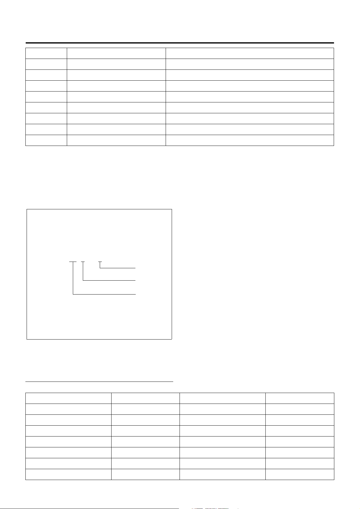
Function and Operation
Electronic Control System
The electronic control system processes the data,
which has been collected with various types of sensors,
by means of the control program installed to ECM
(engine control module) to totally control engine
parameters such as fuel injection amount, injection
timing, engine startup, altitude compensation, and
EGR.
Sensor Actuator Control
Engine Rotating Speed
(Built-in Injection Pump)
Crankshaft Position
Accelerator Position
Coolant Temperature
Fuel Temperature
(Built-in Injection Pump)
Intake Air Pressure
Vehicle Speed
ECM
Engine Driver Unit
Injection Pump
Spill Control Valve
Timing Control Valve
EGR Valve
Engine
Control
Module
Intake Throttle Valve
Exhaust Magnetic Valve
Fuel Injection Volume
Control
Fuel Injection Timing
Control
Idle Rotating Speed
Control
Starting Control
Altitude Control
EGR Control
Intake Air Throttle
Control
Exhaust Brake Control
Idle Up Volume
Intake Air Temperature
Atmospheric Pressure
(Built-in ECU)
ECM
ECM Description
The ECM is mounted in the glove box. The ECM
monitors va ri ou s da ta se n t fr om d iv e rsi fi e d se ns or s a n d
controls systems in the powertrain. The ECM
diagnoses these s ystems to detect faults with resp ect
to system operations and inform the driver of faulty
condition via the CHECK ENGINE Lamp (MIL) and
stores DTCs (diagnosti c trouble codes ). DTC identifi es
the trouble generation area to aid repairs by service
operators.
Glow Plug
Glow Lamp
CHECK ENGINE Lamp
Swirl Change-Over Valve
Warm-Up System
Control
Starting Aid Control
Self Diagnosis
Intake Air Swirl Control
LNW21ALF000301-X
Function of ECM
ECM supplies 5 V and 12 V voltages to various sensors
and switches. Since powers are supplied via high
resistances in ECM , Test Light, eve n when connected
to the circuit, will not be lit. In a spe cial case, a normal
voltmeter does not indicate correct values since the
resistance of the instru ment is to o low. To get accu rate
readings, you need a digital voltmeter whose input
impedance is at least 10 M Ω. The special tool 5-88400366-0 is a pro per ch oice fo r this m easurement. In t he
ECM, the output circuit is con trolled by regulating the
Page 7
Engine Control System 1A-5
grounding system or power circuit via transistor or
either of the devices listed below.
• Output driver module (ODM)
• Quad drive module (QDM)
ECM and Components
The ECM is designed to offer excellent drivability and
fuel economy while achieving exhaust gas emission
control requirements. The ECM monitors engine and
vehicle functions via various electronic sensors such as
CKP (crank position) and VS (vehicle speed) sensors.
Voltages from ECM
The ECM supplies reference voltages to various
switches and sensors. Resistances of the ECM are
very high and this allows the ECM to supply voltages to
these devices, and voltag es actually applied to circuits
are low and even connecting Test Light to individual
circuits may fail turn-on. Since the voltmeter normal ly
used in service factories has low input impedance,
correct readings may not be obtained . To get a ccurate
readings, a digi tal voltm eter whose i nput impeda nce is
10 MΩ (for example, 5-8840-0366-0) should be used.
Input/output devices of the ECM include analog-todigital converter, signal buffer, counter, and special
driver. By using electronic switches, th e ECM controls
most system components and turning off a switch
closes the ground circuit. These switches are divided
into four-switch or seven-s wit ch groups, and the former
group is called quad dr i ver m odu le ( QD M) an d c ontro ls
up to four output pins respectively while the latter group
is called output driver module (ODM) and controls up to
seven outputs respectively . Note that all the outputs are
necessarily not used in the control.
Electrically Erasable Programmable ROM
(EEPROM)
EEPROM is a permanent memory chip and soldered to
the board in the ECM. EEPROM stores program and
calibration data, both of which are necessary for the
ECM to control the powertrain. Different from
conventional ROMs, EEPROM cannot be replaced with
new component. If EEP ROM fails, the complete ECM
assembly must be replaced with new one.
engine fault to the user.
In a service factory, 4 pins and 6 pins of DLC (data link
connector) can be short to check the DTC while the
CHECK ENGINE Lamp (MIL) is flashing.
LNW21ASH000201
87654321
161514131211109
LNW21ASH000301
Precautions on ECM Service
The ECM is designed to withstand ordinary currents
used in operations of a vehicle. Be careful that the
circuits must not be overloaded. To test the ECM to
check open wiring or short, ECM circuits must be
connected to the ground or voltages must not be
applied to the ECM. To test ECM circuits, the digital
voltmeter 5-8840-0366-0 should always be used.
CHECK ENGINE Lamp (MIL)
Used as a means of communication between ECM and
user usually in the user mode, by light on and off. If this
lamp illuminates during operation, it warns some
Page 8
1A-6 Engine Control System
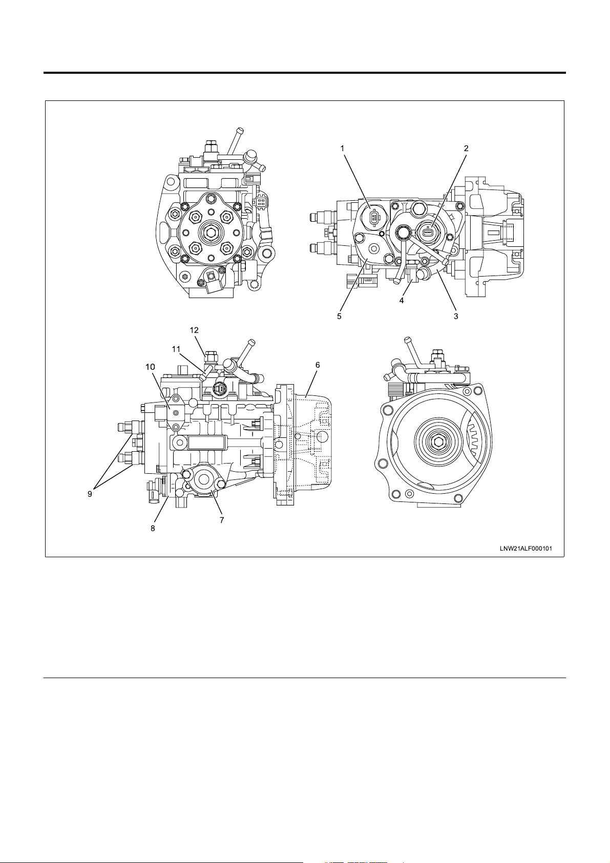
Electronically Controlled Distributor Injection Pump
12
11
10
12
4
5
6
3
9
8
7
Legend
1. Spill control valve
2. Pump cam position sensor (engine speed
sensor)
3. Inlet pipe
4. Fuel temperature sensor
5. Accumulator
6. Bearing cover
An electronically contr olled distribu tor inj ectio n pump is
employed to meet the requirements of the long-term
exhaust gas control without impairing the fuel efficiency
and output. These features allow finer particles of
injected fuel, and optimum injection timing and injection
amount while the vehicle is traveling, which was
impossible with the former injection pump.
LNW21ALF000101
7. Timer
8. Timing control valve
9. Delivery valve holder
10. Compensation ROM
11 . Overflow pipe
12. Overflow valve
Fuel Dehumidifying Agent
Sliding parts in the in jec ti on p ump are lubricated by t he
fuel (light oil) as in the ex isting d istr ibutor ty pe in jecti on
pump. If dehumidifying agent is mixed in the fuel, it
may exert adverse influence on the sliding parts.
Particularly, dehumidifying agent of alcohol type is
characterized by introducing moisture into water,
causing rust generation. It should be explained to
customers not to use fu el dehumid ifying ag ent or other
fuel additives.
Page 9
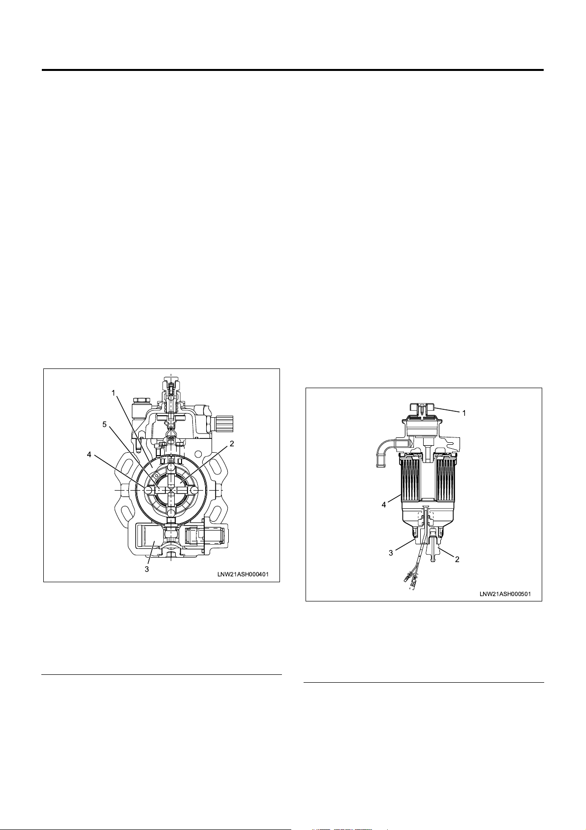
Structure and Operation
1. Higher pressure of injection fuel
An inner cam with a cam ring and radial plunger
are used to in crease the pressure o f the injection
fuel.
The cam ring is supported on th e pump body side
and provided with projections (cams) on the
internal periphery.
Four plungers are provided at an interval of 90°,
incorporated in the rotor i ntegrated with the drive
shaft, and in contact with the internal periphery of
the cam ring in the radial direction through the
roller.
When the drive shaft rotates, the plunger moves
on the cam ri ng int er nal s ur fac e throug h the rolling
of the roller, pushed out in the shaft center
direction with th e inner cam and compresses the
fuel.
Four plungers operate simultaneously. This
enables higher pr essure (75 ~ 130 M Pa) and high
rigidity is o btained since the lo ad bec om es rel ati ve
load in the radial direction.
Plunger diameter is ø7.5mm and the cam lift is
2.5mm.
1
Engine Control System 1A-7
3. Fuel injection amount control
Fuel injection amount is adjusted by opening or
closing the fuel high pressur e circuit with the high
response SPV (spill control valve).
EDU (engine driver unit; a high voltage driver) is
employed to drive the SPV at a high speed . EDU
can drive the SPV o f high fuel pressure at a high
speed by the high voltage and high speed
energizing system.
4. Pump ROM
In order to compensate the variation of correlation
between the fuel pump and engine, variation of the
injection amount in herent to the injection pump is
corrected.
5. Air bleeding of injection pump
a. Pumping until the pump is hard to operate.
b. Start the engine. If not started, repeat
pumping.
c. After the engine is started, keep the engine
speed at 1000 to 1500rpm for about 10
seconds.
d. Stop the engine.
e. Check for fuel leakage.
5
2
4
3
LNW21ASH000401
Legend
1. Cam ring
2. Rotor
3. Timer piston
4. Roller
5. Plunger
2. Injection timing control
Injection timi ng is ad ju sted by shifting the cam ring
phase with the fue l p ress ure app li ed t o th e back of
the timer piston. The fuel pressu re applied to the
timer piston is controlled with the ECM (engine
control module) through the timing control valve.
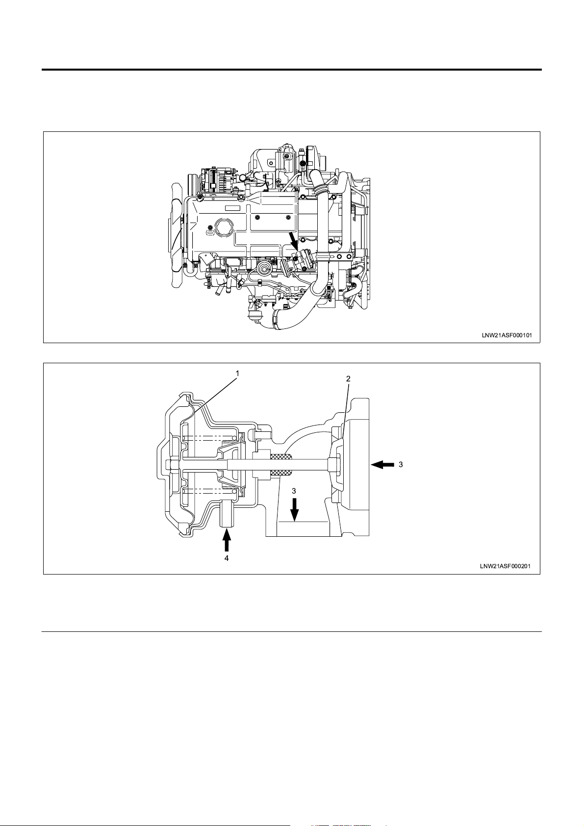
Legend
1. Priming pump
2. Plug
3. Sensor
4. Cartridge
1
4
3
2
LNW21ASH000501
Page 10
1A-8 Engine Control System
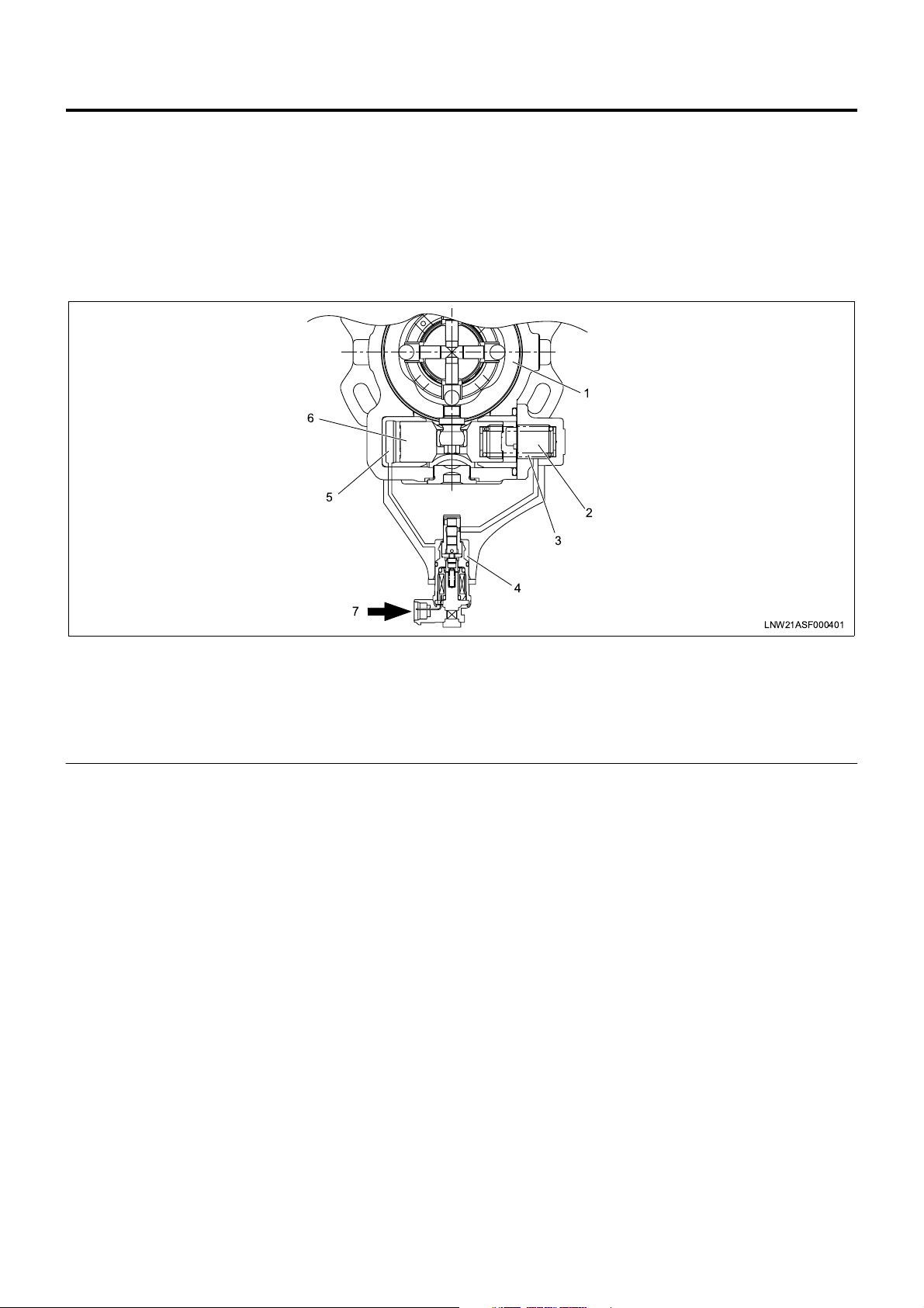
EGR (Exhaust Gas Recirculation) Valve
In order to decrease NOx (nitrogen oxide) in the
exhaust gas, an EGR system is employed.
The EGR valve is vacuum control type.
LNW21ASF000101
Legend
1. Diaphragm
2. Valve
1
3
4
2
3
LNW21ASF000201
3. Exhaust gas
4. Vacuum
Page 11
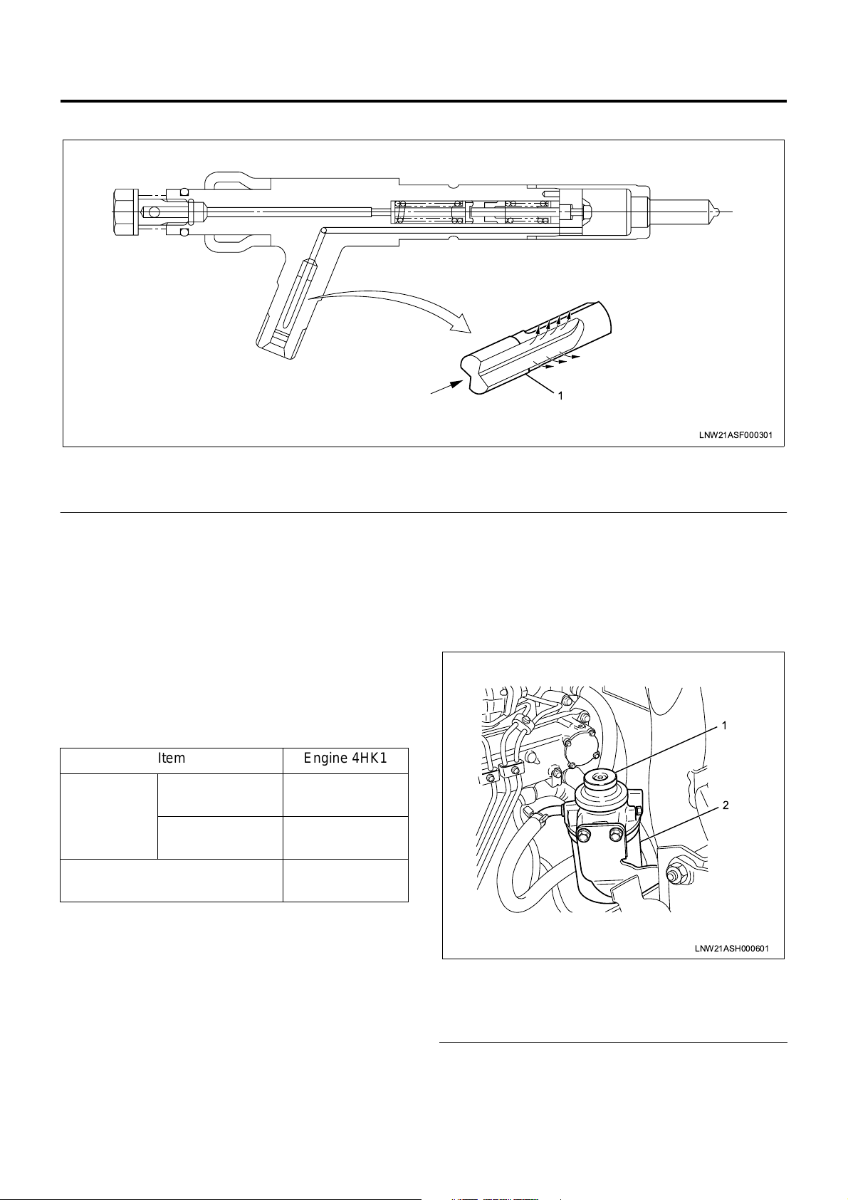
Injection Nozzle
Legend
1. Edge filter
Engine Control System 1A-9
1
LNW21ASF000301
A two-step valve opening pressure nozzle is used as
the injection no zzle. Spray pa rticle size i s reduced by
reducing the injection hole diameter.
To prevent clogging of the nozzle injection hole, an
edge filter is provided at the nozzle holder inlet.
Reference:
If the injection nozzle hole is clogged, ECM corrects the
cylinder inside condition.
The cylinder correction amount in the Tech 2 data list is
helpful to know the injection nozzle condition.
Item Engine 4HK1
Valve
opening
pressure
MPa(kg/cm
1st valve op ening
pressure
2nd valve
2
)
opening pressure
No. of injection holes - Injection
18.0 {185}
(Nominal value)
22.0 {225}
(Nominal value)
5 -ø0.25
hole diameter (mm)
Fuel Filter with Sedimentor
In order to secure the lubrication efficiency in the
injection pump, a fuel filter with sedimentor to remove
moisture in the fuel is provided.
This filter is pro vided with a priming pump to bleed th e
air from the injection pump.
1
2
LNW21ASH000601
Legend
1. Priming pump
2. Fuel filter & sedimentor
Page 12
1A-10 Engine Control System
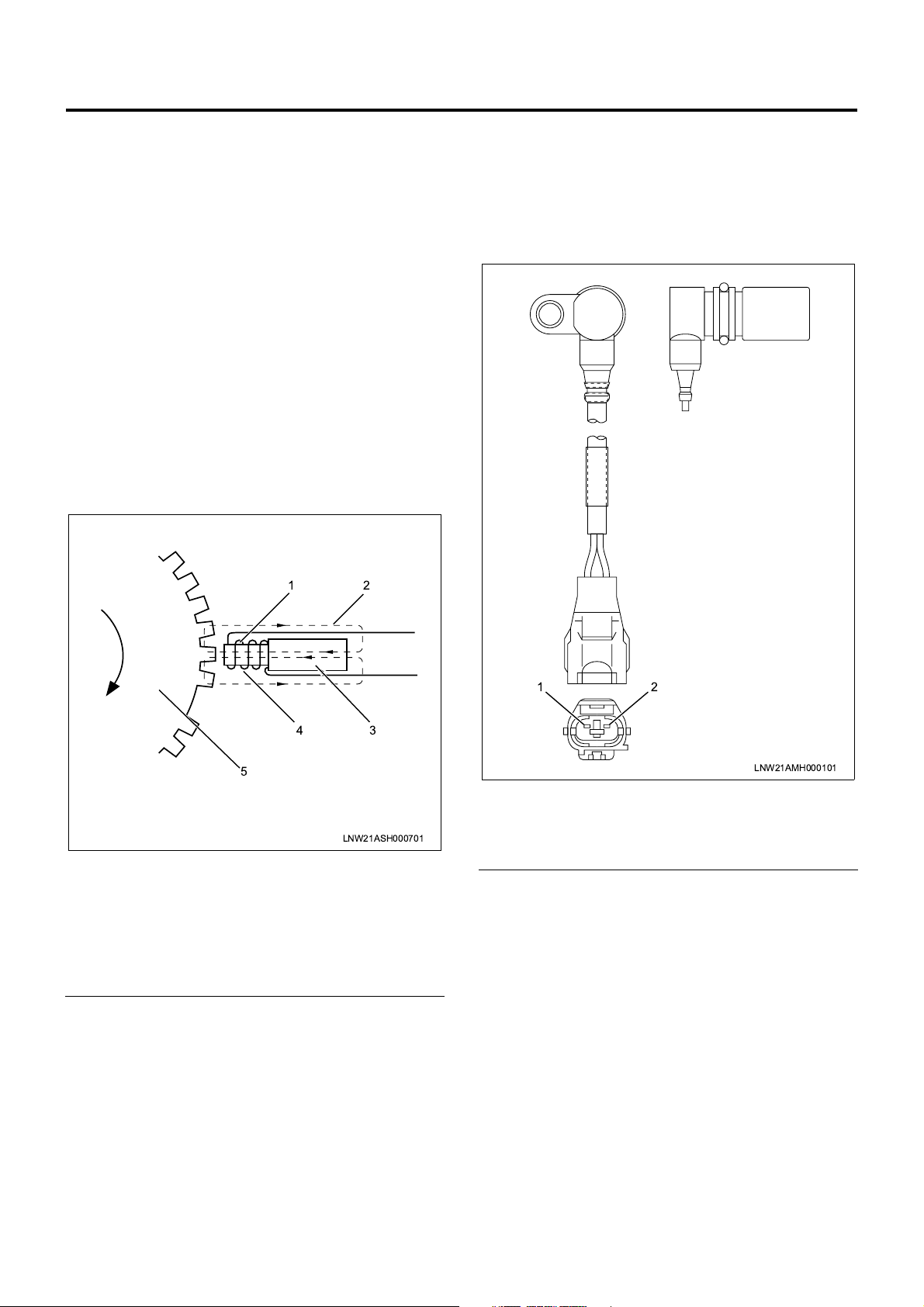
Pump CMP (Cam Position) Sensor (Engine Rotation
Sensor ) = NE Sensor
The pump CMP sensor is positioned on the outer
surface of the cam ring of the pump chamber. The
pulser installed to the injection pump drive shaft
interrupts the magnetic flux generated by the
permanent magnet and iron core of the sensor
according to the shaft rotation to generate AC wave
signal to the coil. This is transmitted to ECM (engine
control module) and converted to square wave signal .
engine speed and cam position are calculated by this
signal.
• Calculation of engine speed: No. of pulses per
hour is counted.
• Calculation of cam position: When the cam ring
slides, timing of sign al read from the pulse of the
sensor installed to the cam ring varies. ECM
calculates the time difference be tween this signal
and signal of the crank position sensor and
calculates the cam position.
CKP (Crank Position) Sensor
CKP sensor to detec t the crank position is installed to
the flywheel housin g. The sensor detec ts the rotating
angle of the crankshaft in non-contact condition with
the pointer installed to the flywheel and sends pulse
signal to ECM. ECM calc ulates the injection timin g at
the pump cam position based on this pulse signal.
Legend
1. Iron core
2. Magnetic flux
3. Permanent magnet
4. Coil
5. Pulser
12
21
34
5
LNW21AMH000101
Legend
LNW21ASH000701
1. (–) Pin
2. (+) Pin
Page 13
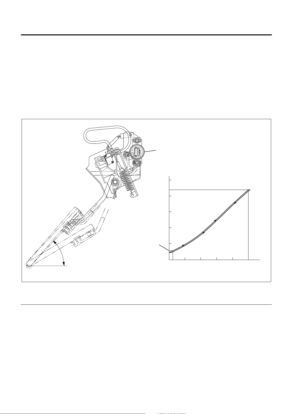
Accelerator Position Sensor
The accelerator control is accelerator position sensor
type. This sensor is a potentiometer (variable
resistance) installed to the accelerator pedal.
Reference voltage i s constantly applied to the sens or
from ECM (engine control modul e) and the accelerat or
pedal stepping ang le is detected from varying voltage .
An accelerator switch (idle position switch) is also
installed to the accelerator pedal. The accelerator
switch is turned ON when the accelerator pedal is
released and OFF when the accelerator pedal is
stepped on.
Engine Control System 1A-11
1
(V)
5
(WOT)
4
3
2
Output Voltage
2
1
49
(Idle)
0
10 20 30
Stroke (on Pedal)
Legend
1. Accelerator position sensor 2. Accelerator switch operating point
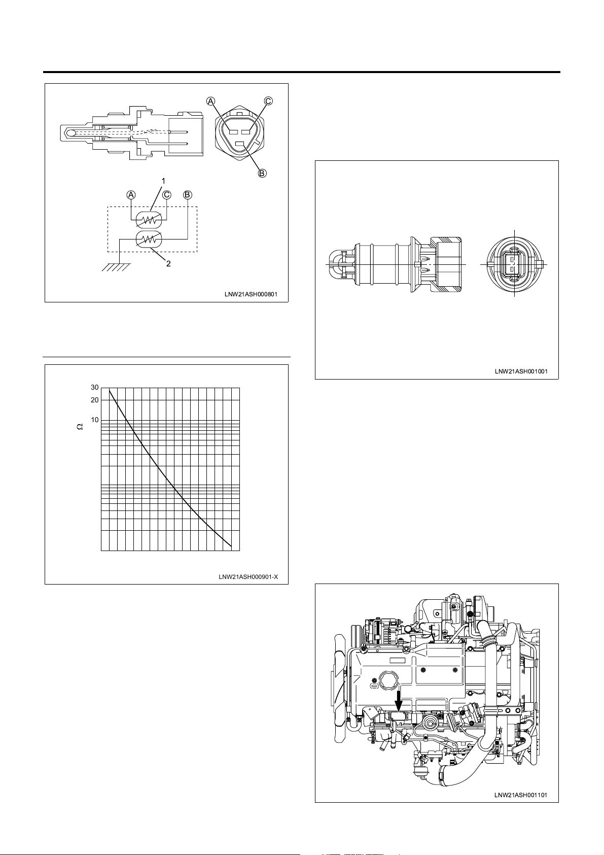
Engine Coolant Temperature Sensor (Coolant
Temperature Sensor / ECT)
The engine coolant tempe ratur e s ensor se rves for both
the ECM and thermo m eter unit. The engine coolant
temperature sensor is of the thermistor type that the
electric resistance reduces with the increase of the
temperature. It is installed on the left front of the
cylinder head.
40 50 (mm)
LNW21AMF000701-X
Page 14
1A-12 Engine Control System
Intake Air Temperature Sensor
AC
Intake air temperatur e sensor is installed to the i ntake
duct. Thermistor is used for the temperature detec tor
as in the thermo sensor to convert the changes of
temperature to changes of resistance values and
transmits to ECM.
ACB
Legend
1. Thermistor for ECM
2. Thermistor for thermo meter
[Thermistor Characteristics]
30
20
10
7.0
5.0
3.0
2.0
1.0
0.7
Resistance Value (k )
0.5
0.3
0.2
0.1
-20 1200 10020 8040 60
Engine Coolant Temperature ( C)
1
2
LNW21ASH000801
B
LNW21ASH001001
Atmospheric Pressure Sensor
The atmospheric pressure sensor is incorporated in
ECM.
MAP (Intake Air Pressure) Sensor
The MAP sensor is installed to the cylinder head cover.
The MAP sensor is composed of piezo type
semiconductor pressure element. Reference voltage is
constantly applied to the MAP sensor from ECM and
manifold pressure is detected by the changes of
voltage. When the manifol d pressure is low ( at idling),
low voltage signal is sent to ECM and when the
pressure is high (at ful l throttle), high voltage signa l is
LNW21ASH000901-X
transmitted to ECM.
Fuel Temperature Sensor
Fuel temperature sensor is installed in the pump
chamber full of fuel. Thermistor is used for the
temperature detector as in the thermo sensor and
convert the changes of temperature to changes of
resistance and values transmits to ECM.
Vehicle Speed Sensor
The vehicle speed sensor is used commonly with the
speedometer. ECM receives signal from the
speedometer.
By one turn of the sp eedome ter driven gear, 25 pulses
are generated indicating 60 km/h at 637rpm.
LNW21ASH001101
Page 15
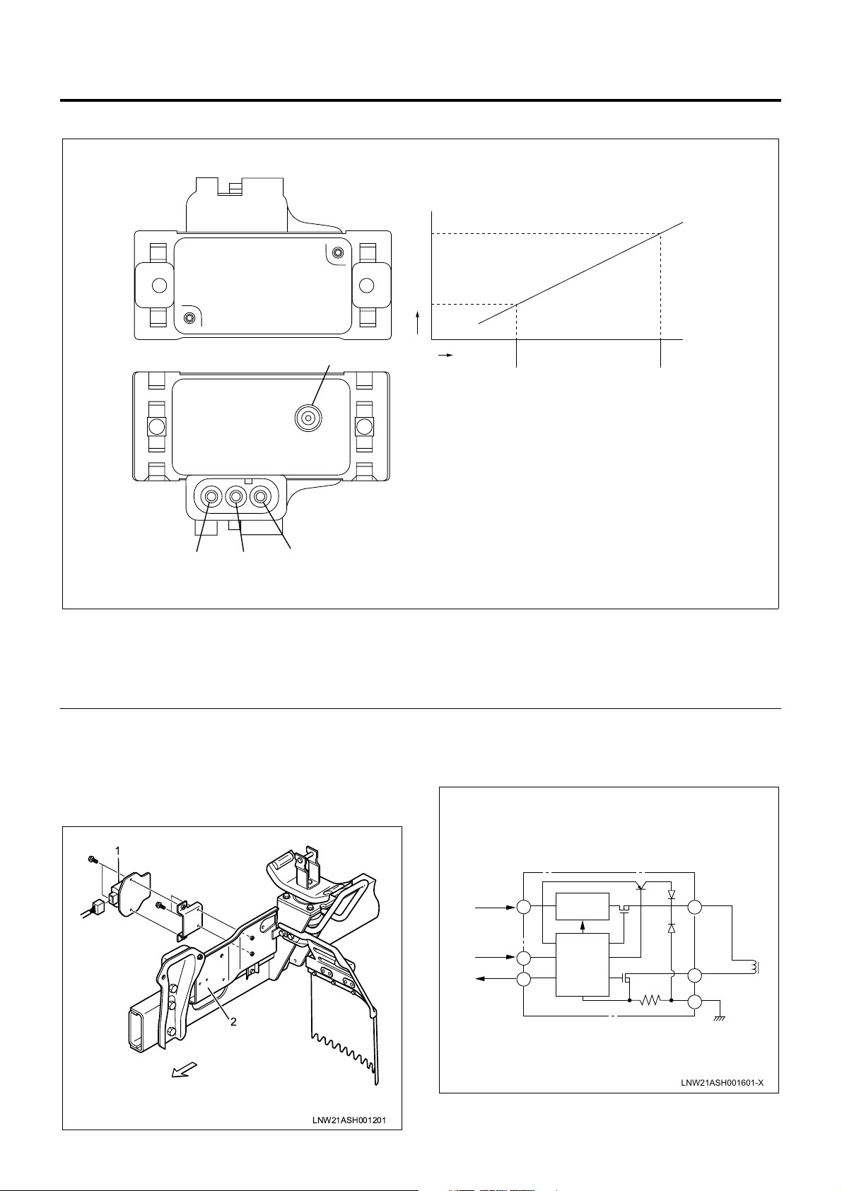
MAP (Intake Air Pressure) Sensor
Engine Control System 1A-13
[MAP Sensor Characteristics]
Output Voltage (V)
6
5
4
3
Legend
1. Pressure at idling (low pressure)
2. Pressure at ratin g p oint (a bsolut e pre ssure (high
pressure))
3. Power pin
EDU (Engine Driver Unit)
EDU enables SPV high speed drive at high fuel
pressure by the high voltage and high speed energizing
system.
Maximum charging voltage is about 150V.
Absolute
Pressure
4. Output pin
5. Ground pin
6. Vacuum hose connected pipe
Legend
1. EDU
2. Left side cover
21
LNW21AMF000801-X
1
2
LNW21ASH001201
Connecting Diagram
Battery
ECM
ECM
A
B
C
High Voltage
Generating
Circuit
Control
Circuit
SPV+
D
E
SPV
F
Ground
LNW21ASH001601-X
Page 16
1A-14 Engine Control System
SPV (Spill Control Valve)
Fuel injection amount is controlled with the highresponse SPV by opening and closing the fuel high
pressure circuit.
SPV is incorporated in the injection pump.
Legend
1. SPV drive signal
2. EDU
3. ECM
4. High pressure fuel
B
B
6
7
5
1
2
3
4
8
LNW21AMF000901
5. Valve
6. High pressure fuel passage
7. SPV
8. B-B section
Page 17
TCV (Timing Control Valve)
TCV using a solenoid valve is installed to the oil
pressure timer. Duty (energizing rate) controlled
current with ECM increases or decreases the valve
opening time to control the oil pressure in the high
pressure chamber si de. The timer piston is mo ved by
the balance with the timer s pring. By sliding the cam
ring connected movably with the timer piston in the
rotating direction, the injection timing is controlled.
6
5
Engine Control System 1A-15
1
2
3
7
Legend
1. Cam ring
2. Low pressure chamber
3. Timer spring
4. TCV
Electronic Control Distributor Pump System
System Overview
The accelerator control uses an accelerator position
sensor. The accelerator sensor of the potentio meter
(variable resistanc e) type is installed to the ac celerator
pedal. Reference volta ge is constantly applied to the
sensor from the ECM (engin e con tr ol module) to det ec t
the accelerator ped al stepping angle from changes of
voltage. An idle posi tion switc h (acceler ator switch ) is
also installed to the accelerator pedal. The idle position
switch (accelerator switch ) is turned ON when the
accelerator pedal is released and OFF when the
accelerator is stepped on.
ECM detects the accelerator pedal stepping angle as
AP (accelerator position) signal and after calculating,
transmits SPV (spill controller valve) drive signal to
EDU (engine driver unit).
EDU enables high spee d drive of SPV which controls
fuel injection amount.
The fuel injectio n amount is contr olled by opening and
closing the fuel high pressure circuit with the high
response SPV.
SPV is incorporated in the injection pump.
The spill control valve and timing control valve are
4
LNW21ASF000401
5. High pressure chamber
6. Timer piston
7. From ECM
electronically controlled with ECM (engine control
module).
Page 18
1A-16 Engine Control System
4
17
16
15
A
B
B
A
3
2
1
18
14
5
6
7
19
13
12
10
9
8
11
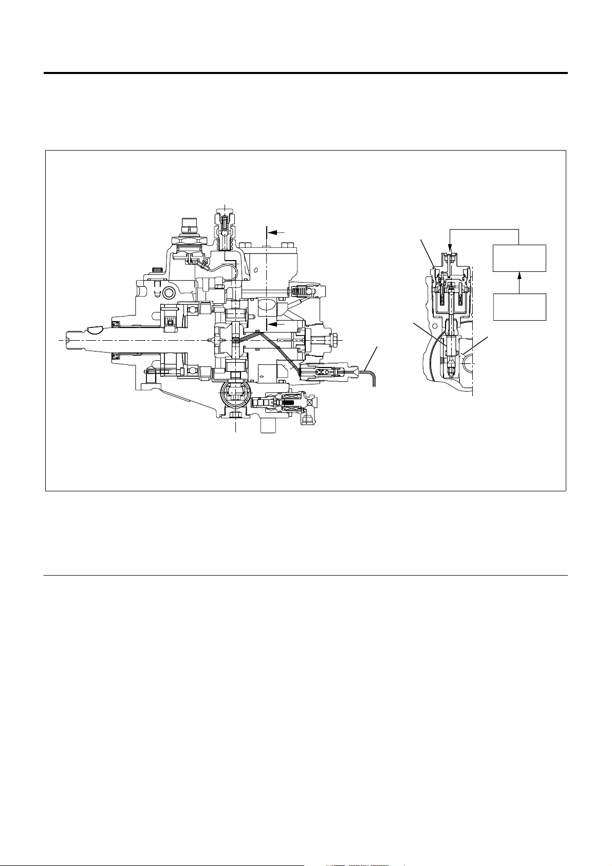
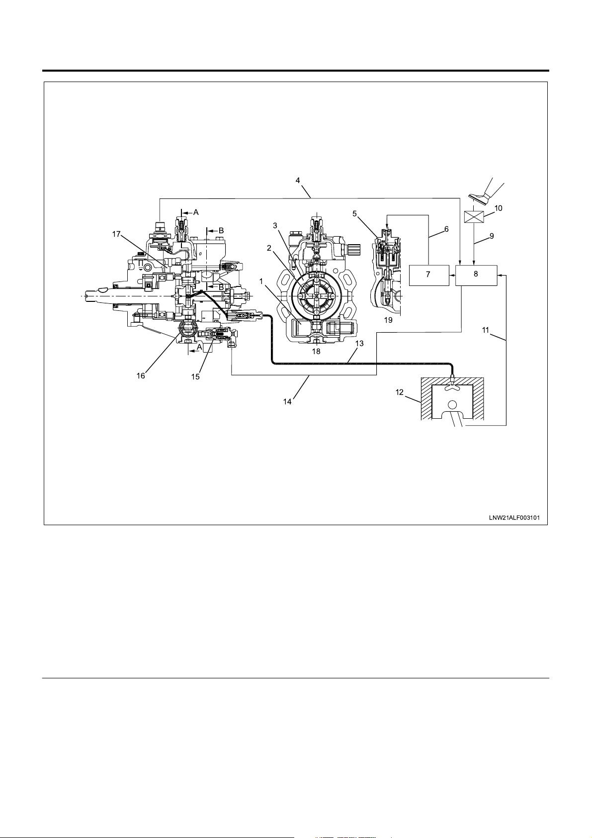
Legend
1. Timer piston
2. Plunger
3. Cam ring
4. Pump cam position signal (engine speed signal)
5. Spill control valve
6. Spill control valve drive signal
7. Engine driver unit
8. Engine control module
9. Accelerator pedal opening signal
10. Accelerator position signal
Fuel Injection Amount Control
The electromagnetic spi ll valve is o pened by the signal
from ECM (engine contr ol m odul e) , pres su r e in the fuel
forced feed unit (rotor unit) is decreased and injection is
completed. Injection amount is controlled at this timing.
LNW21ALF003101
11. Crankshaft position signal
12. Engine
13. High pressure fuel passage
14. Injection timing control si gna l
15. Timing control valve
16. Timer piston
17. Pump cam position sensor (engine speed
sensor)
18. A-A section
19. B-B section
Page 19
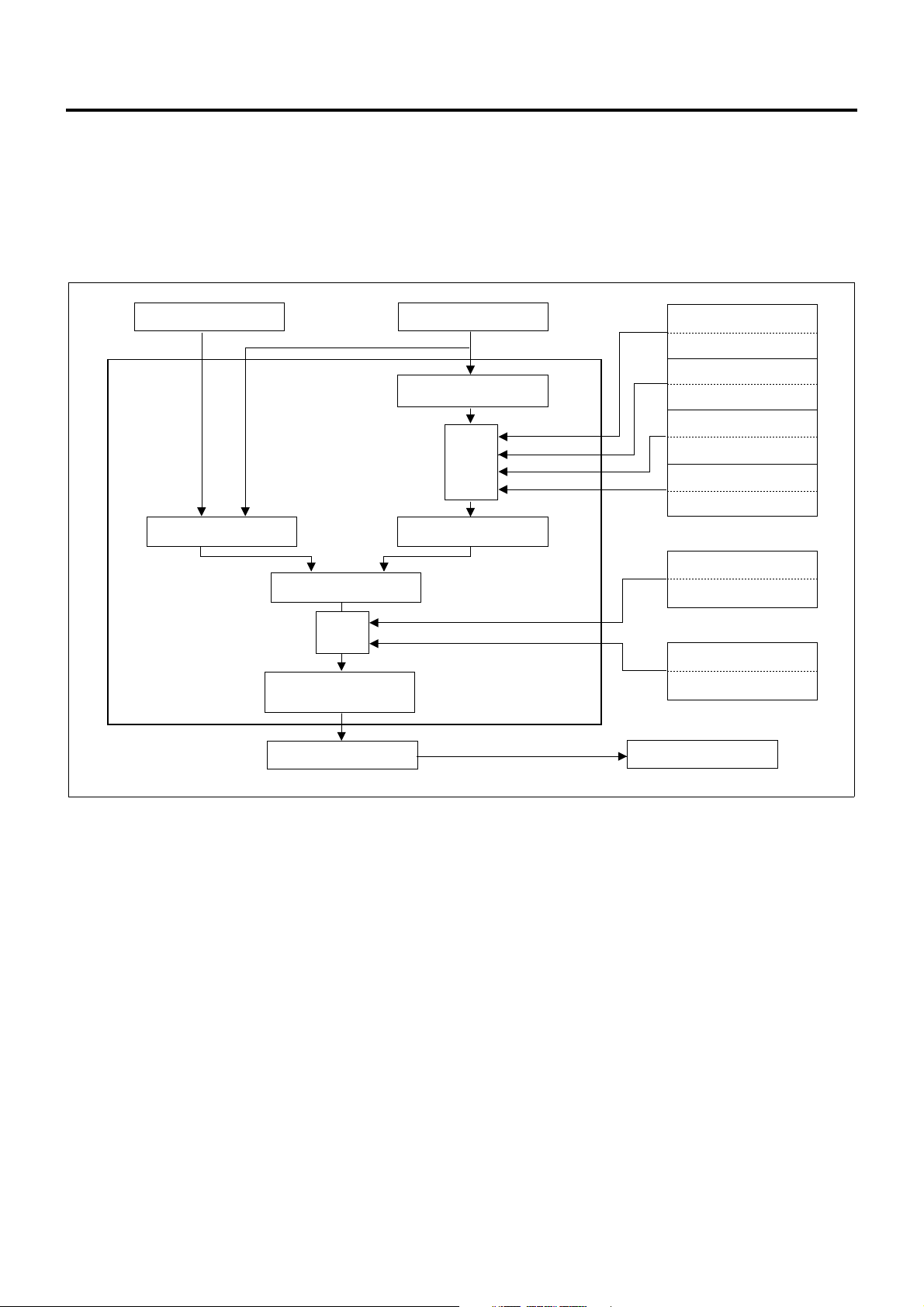
Operation
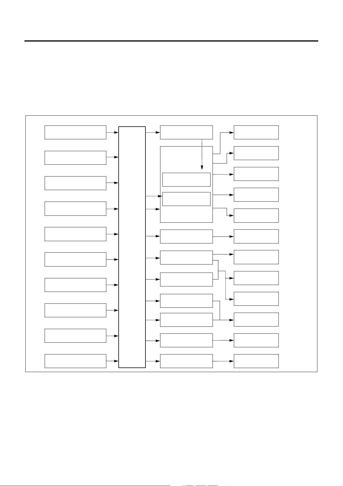
ECM calculates the bas ic injection amount op timum to
the engine operating conditions and the maximum
injection amount at that engine condition, compares
and selects lower injection amount. By adding the
phase compensated with the compensation ROM to
that injection amount, the final injection amount is
determined.
Engine Control System 1A-17
At the time of start, the optimum fuel injection amount is
determined by the starter signal and coolant
temperature. (Injec tion amount increases more wh en
the coolant temperature is lower.)
Accelerator Position
Sensor
Basic Injection Amount
Select Lower Injection
Amount Side
Compen-
sation
Injection Amount
Determine
EDU
Engine Speed Sensor
Basic Max. Injection
Amount
Compen-
sation
Max. Injection Amount
Intake Air Pressure
Sensor
Increase When Higher
Intake Air Temperature
Sensor
Varying Depending on
Conditions
Fuel Temperature Sensor
Increases When Lower
Coolant Temperature
Sensor
Increases When Lower
Fuel Temperature Sensor
Compensates to Increasing
Side When Higher
Compensation ROM
Compensation Value
of Each Pump
Electromagnetic Spill Valve
LNW21AMF001001-X
1. Basic injection amount
Determined by accelerator opening and engine
speed.
2. Max. injection amount
Maximum injection amount is determined by
adding compensati on by signals of sen sors to the
basic maximum injection amount (amount which
can be theoretic ally in jec ted ) dete rm in ed ba se d on
the engine speed.
a. Intake air pressure compensation
When the intake air pressure is high, the air
amount is increased and the injection amount is
increased.
b. Intake air temperature compensation
Injection amount is increased or decreased
depending on the difference of density based
on the intake air temperature.
c. Fuel temperature compensation
When the fuel temperature decreases, the
injection amount is increased.
d. Coolant temperature compensation
When the coolant temperature is lower, the
injection amount is increased to secure the
operability immediately after the cold start.
3. Injection amount compensation
Since the actual injection amount decreases in
comparison with the des ignated value of injection
amount when the fuel temperature is higher,
designated injection amount value is increased.
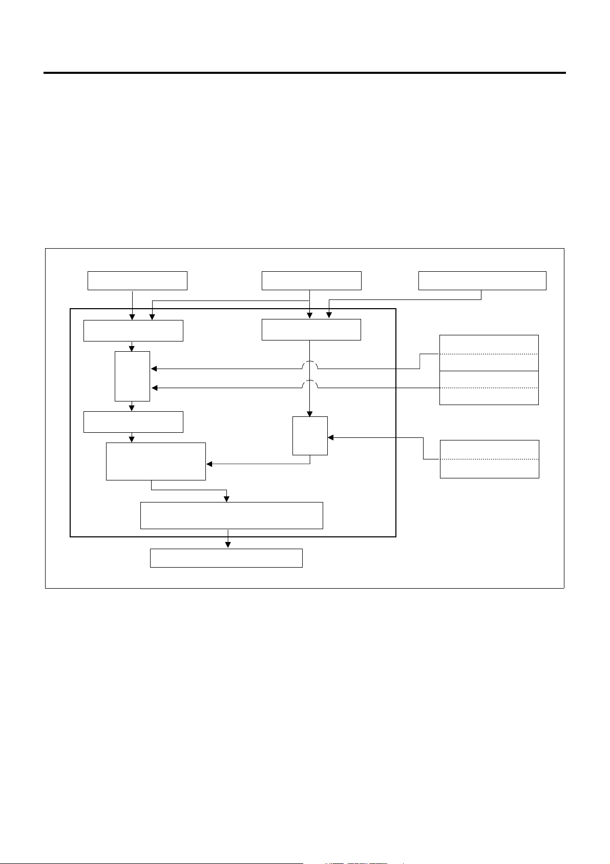
Fuel Injection Timing Control
• Timing control valve is duty-controlled according to
a signal from ECM (engine control module) to
control the fuel injection start timing.
• Using the crankshaft angle feed back system,
highly precise control is effected.
Page 20
1A-18 Engine Control System
Operation
ECM calculates the o ptimum target injection ti ming for
the engine condition, adding the compensation by
signals from sensors based on the basic target
injection timing.
At the time of start, the injection timing is determined by
the starter signal, coolant temperature and engine
speed (at the higher engine spee d, the injecti on timing
angle advances.)
Crank angle feed back system is emp loyed to c alculate
the actual inject ion timing and feed back the res ult at
the target injection timing.
Accelerator Position
Sensor
Basic Target Injection
Timing
Compen-
sation
Target Injection Timing
Comparison with Target
Injection Timing and
Actual Injection Timing
Calculation of Duty Ratio
Actual Injection Timing
Timing Control Valve
Speed Sensor
Compen-
sation
Crank Position Sensor
Intake Air Pressure
Sensor
Angle Advances
When Lower
Coolant Temperature
Sensor
Angle Advances
When Lower
Compensation ROM
Compensation Value
of Each Pump
1. Basic target injection timing
Determined based on the accel erator opening and
engine speed.
2. Injection timing compensation
a. Intake air pressure compensation
Basic target inje ction timing is compens ated by
the intake air pres sure. Whe n the at mospheric
pressure is low on a altitude, for instance, the
injection timing angle is advanced.
b. Coolant temperature compensation
Basic target injection timing is compensated
based on the coolant tem perature. When the
coolant temperatu re is low, the injection timing
angle is advanced.
LNW21AMF001101-X
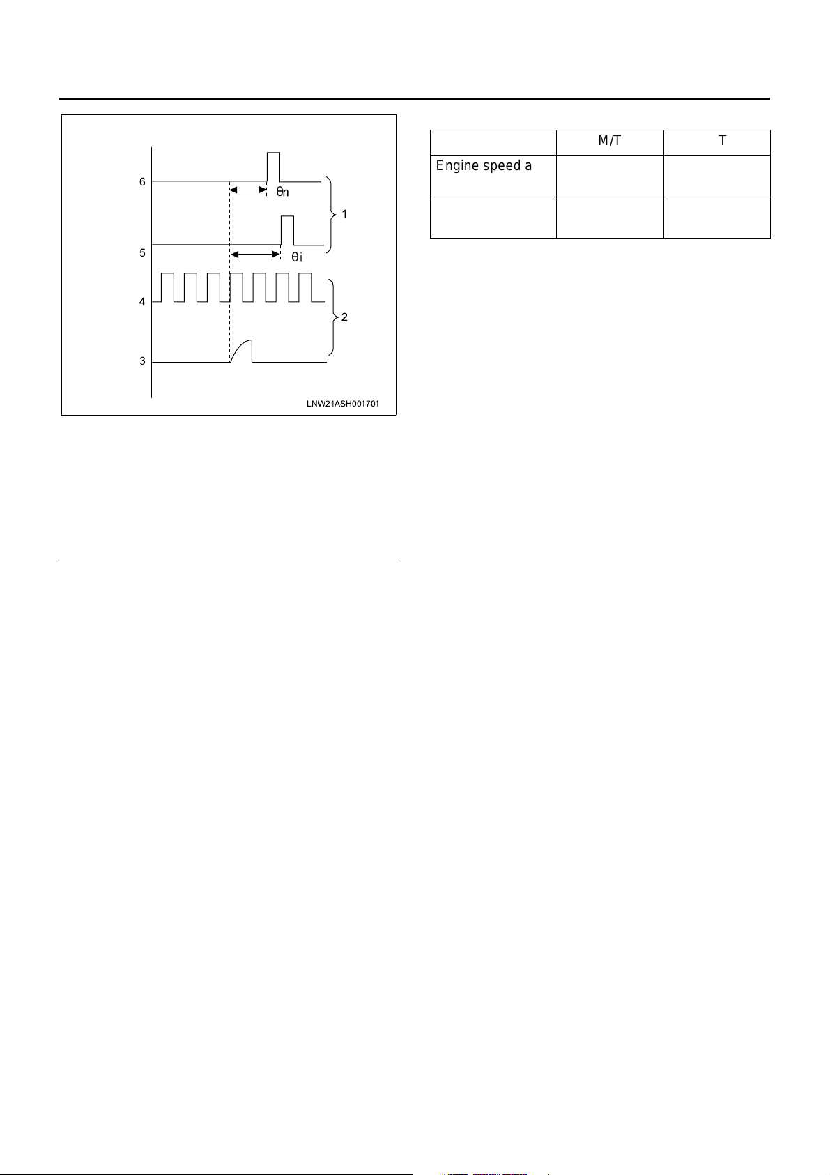
3. Feedback control
a. Calculation of actual injection timing
When relation between the compression TDC
position and crank angle reference position
signal is correct on the engine side and the
relation between the injection waveform and
cam angle signal is cor rect on the pump side,
actual injection timing θn can be calculated by
calculating the phase di fference θi between the
crank angle refere nce position signal and c am
angle signal.
Page 21
Engine Control System 1A-19
Idle Speed (P.N Range in A/T Vehicle) [r/min]
M/T A/T
6
5
4
3
θ
Legend
1. Engine
2. Pump
3. Injection waveform
4. Cam angle signal
5. Crank angle reference positi on signal
6. Actual compression TDC
θ
LNW21ASH001701
Engine speed at
no load
1
2
Air conditioner
system ON
Approx. 580 Approx. 650
Approx. 800 Approx. 870
b. Feedback control
Timing control valve duty ratio is cal culated so
that the actual injection timing coincides the
target injection timing.
Idle Speed Control
• Idle speed is controlled by increasing or
decreasing the specified fuel injection amount
value based on the signal from ECM (engine
control module).
Operation
1. Feedback control
When there is a difference between the target
speed calculated by the E CM an d eng ine speed at
the idle speed, the fuel injection amount is
controlled by changing the signal to the
electromagnetic spi ll va lv e and co ntrol s s o th at the
engine speed coincides the idle speed.
2. Warm-up control
Optimum fast idle engine speed is controlled at
idling by the coolant temperature.
3. Estimated control
Immediately after changing over the air
conditioning switch, before the engine speed
changes, the injection amount is changed by a
constant amount to preven t change of idle speed
by the change of load given to the engine.
Page 22
1A-20 Engine Control System
Component Layout
Fuse Layout
[Fuse Box Label, In Glove Box]
22
19
16
13
10
1
4
7
25
23
26
[Fuse Box, Front Left of Radiator]
24
1
20
21
17
18
27 28
14
15
11
12
2
5
8
6
9
3
LNW21ALF000401-X
Legend
1. Spare fuse
No. Indication on label Capacity Devices connected
1 CONTROLLER 10A Control unit
HAZARD,HORN (12V) 15A
2
Hazard warning flashing lamp, horn
HAZARD,HORN (24V) 10A
3—10A—
AIR CON (12V) 10A Air conditioner
4
HEATER,AIR CON (24V) 15A Heater, air conditioner
5 FUEL, SEAT HEATER (24V) 10A Fuel, seat heater
6 ABS, HAB, RETARDER (24V) 15A ABS, HAB, retarder
Page 23

Engine Control System 1A-21
No. Indication on label Capacity Devices connected
7 ROOM LAMP 15A Room lamp
8 STOP LAMP 10A Stop lamp
9 POWER WINDOW (24V) 20A Power window
10
11 FOG.CORNER 10A Fog lamp, cornering lamp
12 ELEC.PTO (24V) 10A PTO switch (electric PTO)
13 WIPER,WASHER 15A Wiper, window washer
14 TURN 10A Turn signal lamp
15
16
17 MIRROR 10A Electrically operated mirror
18 CIGAR,AUDIO 10A Cigarette lighter, audio
19
20
21 AIR BAG 10A SRS airbag
TAIL.ILLUMI (12V) 15A
Tail lamp
TAIL.ILUMI (24V) 10A
GENERATOR (12V) 15A Generator
ELEC.PTO (24V) 20A PTO solenoid valve (electric PTO)
MIRROR HEAT (12V) 10A Heated side mirror
ENG.CONT (24V) 15A ECM
METER (12V) 10A
Meter
METER (24V) 15A
ENGINE STOP (12V) 10A Engine stop
HSA (24V) 10A HSA
22 STARTER 10A Starter
23 H/LAMP RH 10A Headlamp, RH
24 H/LAMP LH 10A Headlamp, LH
25
26 POWER WINDOW (12V) 30A Power window
External Fuse Box
No. Indication on label Capacity Devices connecte d
27 MARKER LAMP 10A Marker lamp
28 COND FAN 10A Condenser fan
HEATER (12V) 30A Heater
ENG CONTROLLER (24V) 30A ECM (except for turbocharged vehicles)
Page 24
1A-22 Engine Control System
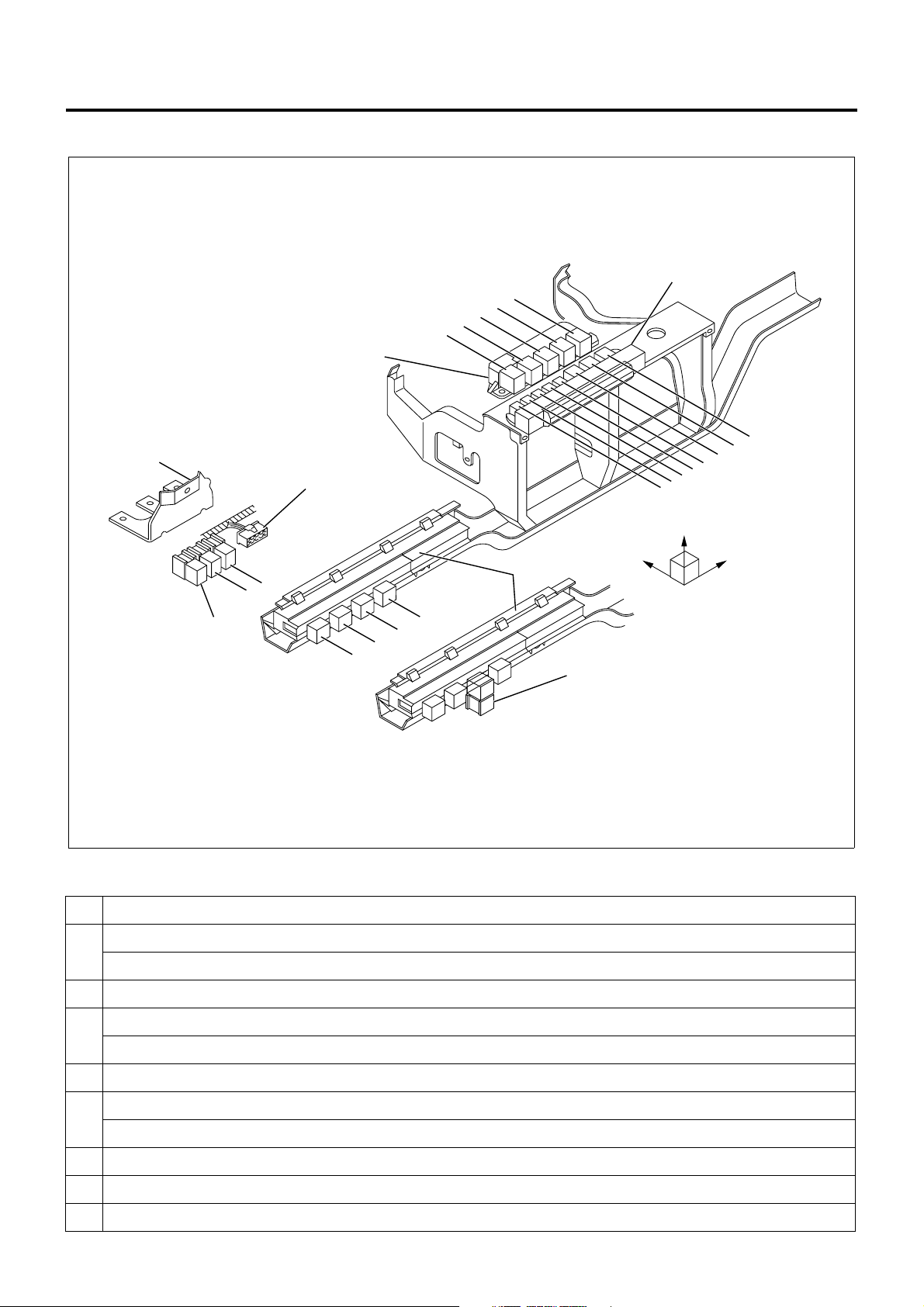
Relay Layout
Relay Box No.2
Bracket
Spare Power Circuit
18
16
15
14
13
Relay Box No.1
8
7
6
5
Upper
12
11
10
9
20
19
Cooler Relay
1
4
3
2
No. Legend
12 V: On relay
1
24 V: C harge relay
2 Horn relay
Fuse &
Relay Box
RightFront
17
LNW21ALF006101-X
12 V: ABS, VSV, FICD, EXH brake
3
24 V: Headlamp relay
4Tail relay
12 V: Headlamp relay
5
24 V: 4WD relay
6 Dimmer relay
7 Power window relay
8 Fog lamp relay
Page 25

No. Legend
9 Cornering lamp relay
10 Air conditioner thermo relay
12 V: C harge relay
11
24 V: Key on relay
12 Heater & air conditioner relay
24 V: PTO cut relay for electric PTO in fire engine (MT)
24 V: PTO solenoid relay for electric PTO (AT)
12 V: Exhaust brake cut relay (MT)
13
24 V: Idle on relay for fire engine (AT)
24 V: Idle stop, wiper relay (with CFS (clutch free system))
24 V: PTO solenoid relay for electric PTO (MT)
24 V: PTO buzzer relay for electric PTO (AT)
12 V: OD off relay (AT)
14
24 V: Idle keep relay for fire engine (AT)
Engine Control System 1A-23
24 V: Idle stop, radio relay (with CFS)
24 V: PTO main relay for electric PTO (MT)
24 V: Garbage relay for garbage collector (AT)
15
24 V: Indicator lamp relay for fire engine (AT)
24 V: Idle stop, engine control module relay (with CFS)
4WD relay
16
24 V: Idle stop, mirror relay (with CFS)
24 V: Full automatic air conditioner, high relay
17
24 V: Automatic air conditioner, high relay
24 V: Shift lock relay for fire engine (AT)
24 V: Shift relay for fire engine (AT)
18
24 V: PTO main relay for electric PTO (MT)
19 24 V: PTO solenoid relay for electric PTO (MT)
20 24 V: PTO cut relay for electric PTO (MT)
Page 26
1A-24 Engine Control System
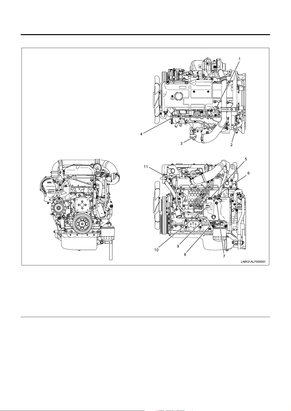
Engine Component Layout
1
4
Legend
1. EGR valve
2. Crank position sensor (CKP sensor)
3. Intake throttle body
4. MAP sensor
5. NE sensor
6. SPV
3
11
10
9
8
7. Fuel temperature sensor (FT sensor)
8. Oil pressure SW
9. TCV
10. ROM
11. Coolant temperature sensor
2
5
6
7
LNW21ALF003001
Page 27
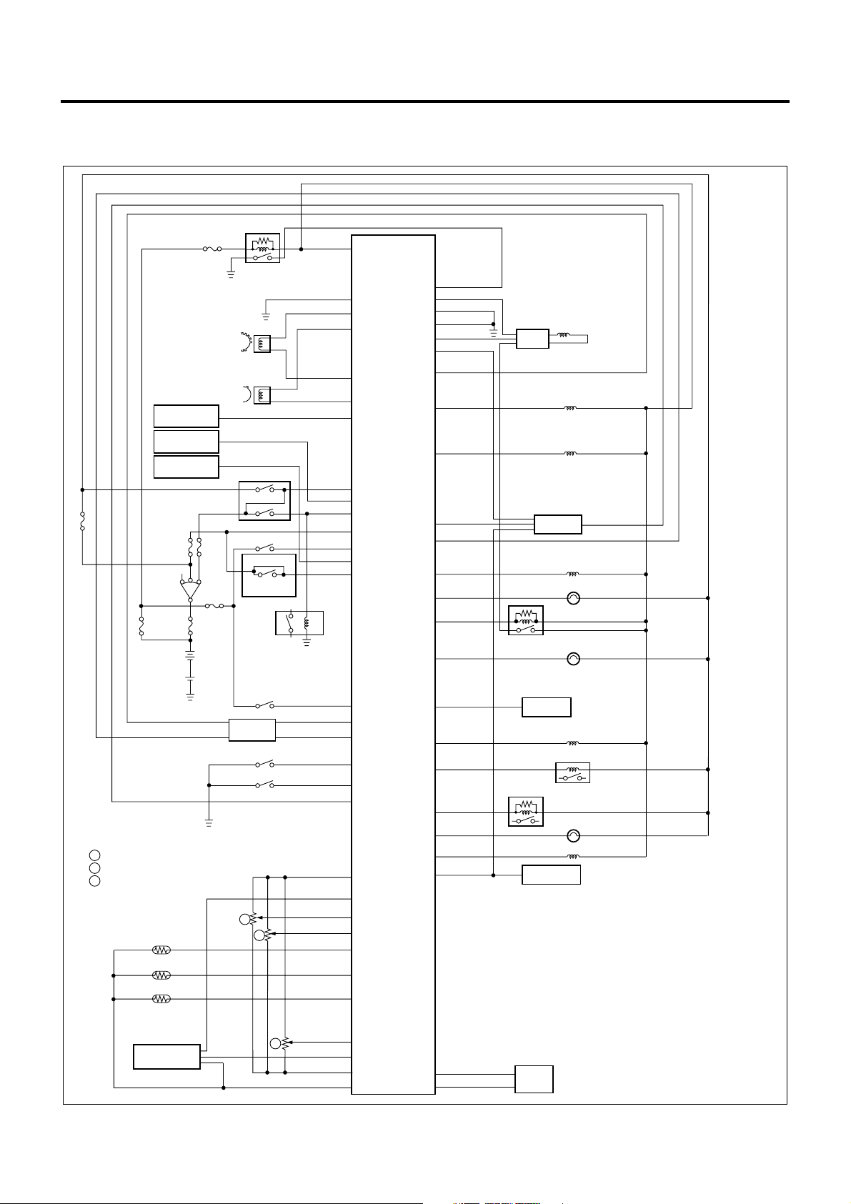
Circuit diagram
ECM wiring diagram (1)
Engine Control System 1A-25
D24
Pump Cam Position Sensor
Crankshaft Position Sensor
Vehicle Speed
Sensor
Cooler
Compressor
Freezer
Compressor
Key SW
1 Accelerator Position Sensor
2 Idle Up Volume
5 PTO Position Sensor
Coolant Temperature
Sensor
Fuel Temperature
Sensor
Intake Air Temperature
Sensor
Main Relay
Neutral SW
Inhibitor SW
Exhaust Brake SW
(A/T)
Clutch SW
(M/T)
Starter Relay
Warm-Up SW
ABS/ASR
ECU
Diagnostic SW
Idle SW
1
2
D13
B6
B5
B12
B11
D7
A17
A20
A2
A3
A21
A19
A6
B2
A16
B8
A9
A10
A5
C3
C4
C11
C10
C1
C12
C15
ECM
D9
D16
D26
A11
D20
A15
D6
D12
A1
B3
B9
A22
D21
D10
D22
A13
D4
D23
B7
D19
A12
B10
Spill Valve
EDU
Timing Control Valve
EGR EVRV
TCM
Swirl Control
Check Engine Lamp
Spill Valve Relay
Glow Lamp
TECH 2
Exhaust Brake VSV1
Glow Relay
Stop Lamp Relay
Exhaust Brake Lamp
Intake VSV
Tachometer
VSV
ECM
: Engine Control Module
EDU
: Engine Driver Unit
EVRV
: Electric Vacuum Regulating Valve
TCM
: Transmission Control Module
VSV
: Vacuum Switching Valve
Intake Air
Pressure Sensor
5
C14
C9
C6
C5 D17
D3
Pump
ROM
LNW21AXF000301-X
Page 28
1A-26 Engine Control System
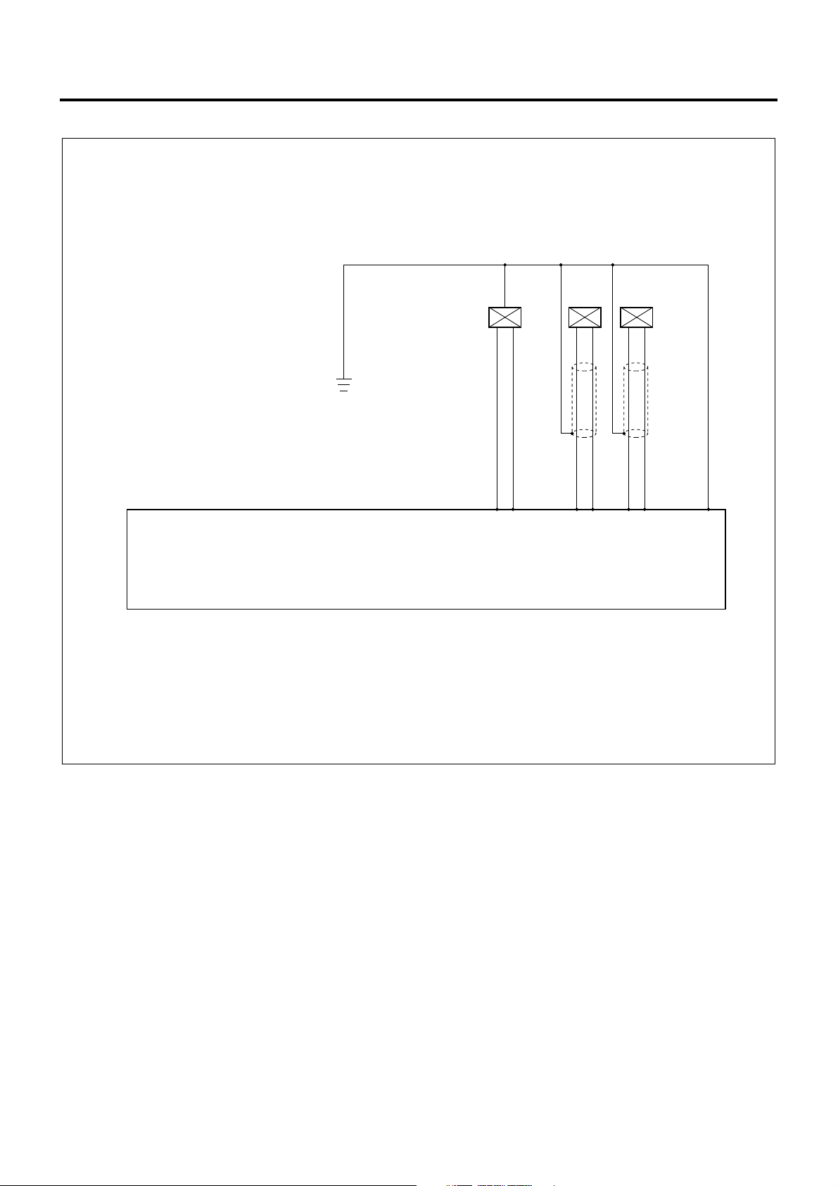
ECM Wiring Diagram (2)
1.25 B/L
CKP
ROM
0.5
0.5
G/B
G/R
Engine Control Module (ECM)
Compensation ROM and NE Sensor are built in the Injection Pump
Sensor
0.5
W
B5
(+)
0.5
R
B11
()
Sensor
0.5
G
B6
(+)
NE
B12
()
0.5
L
D13D3D17
LNW21ALF000701-X
Page 29
ECM Wiring Diagram (3)
Engine Control System 1A-27
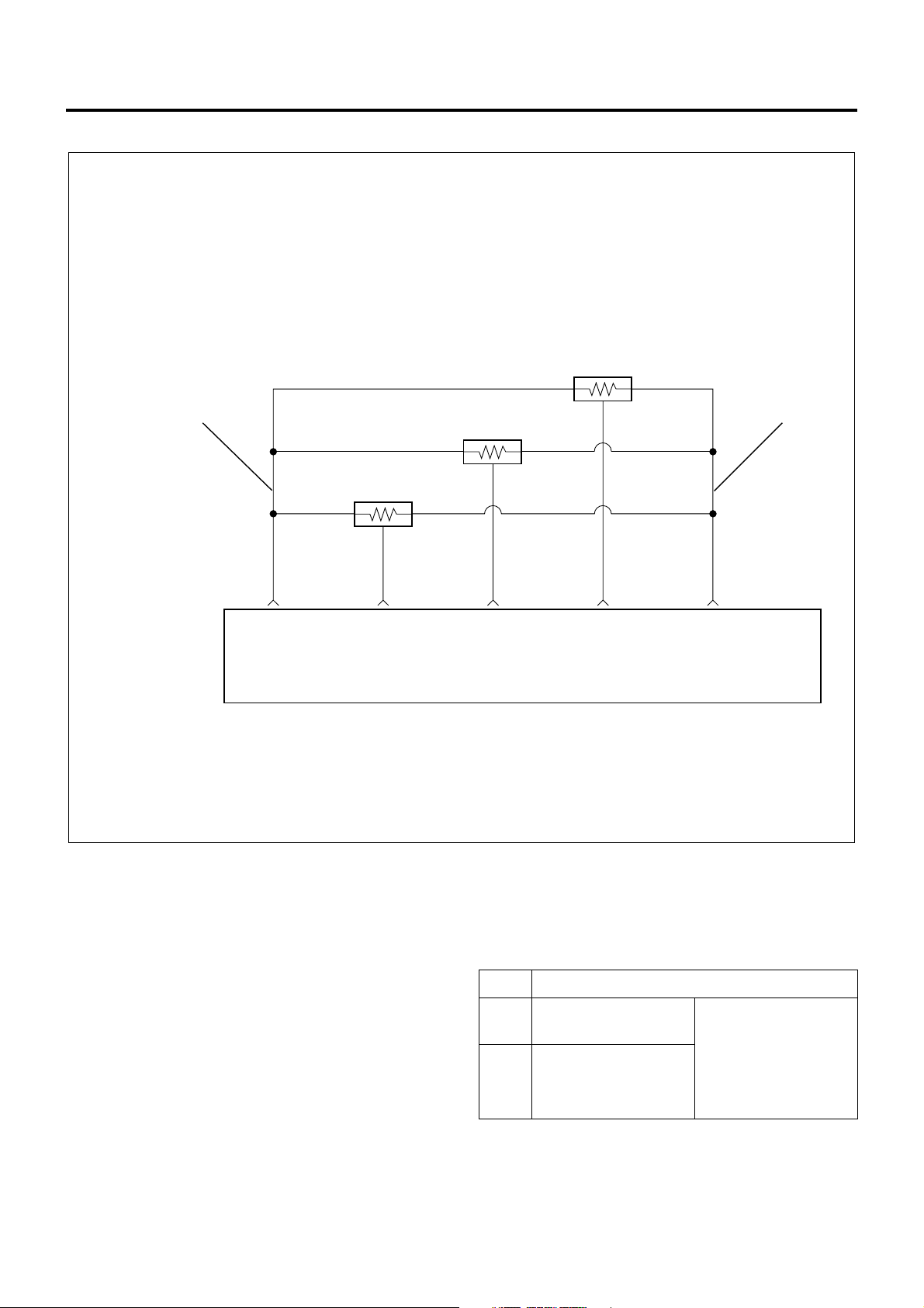
AP (Accelerator Position) Sensor
2 1
Engine Control Module
(ECM)
0.5
Y/B
C6
(Sensor
Ground)
PTO Accelerator Sensor
0.5
R/B
C14
Signal
Idle Up Volume
0.5
Y/G
C10
Signal
0.5
G/O
C11
Signal
0.5
Y/R
C3
(Sensor
Power)
LNW21ALF000501-X
Characteristics of Circuit
• Multiple DTC is generated when several troubles
(failures) occur. When multiple sensors or switches
share a ground, or an open wiring o r short occurs
on the share power sup ply or ground, DTCs with
respect to related sensors or switches are
displayed.
If several DTCs are displayed, it is necessary to
inspect the shared power supply or ground for
open wiring or short.
The harness 1 shown above figure is the power
common to the AP sensor and idle up volume, and
the harness 2 is a common ground. In the event of
open wiring in wire 1 or 2, DTC 24 and 31 are
displayed at the same time. Like this, the case
where two or more DTC’s are displayed is the
multiple DTC.
• If multiple DTC24 and 31 a re di splayed , the power
supply wire 1 or ground wire 2 must be checked.
DTC Sensor actuator (detection item)
24 Accelerator position
sensor
31 idle up volume
Connector not
connected,
harness open wiring,
or
short, failure of
main unit
Page 30
1A-28 Engine Control System
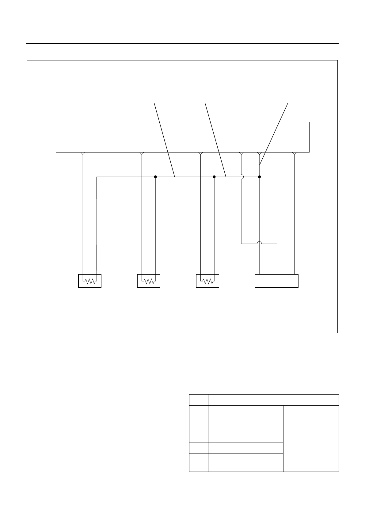
ECM wiring diagram (4)
32 1
ECM
C-1 C-12 C-15 C-9 C-5
0.5
Y/G
0.3
0.5
BLU/
RED
W/
GRN
SIG
Engine Coolant
Temperature
Sensor
GND
0.3
0.5
R/G
W/
GRN
SIG
GND
Fuel Temperature
Sensor
0.3
0.5
R/Y
W/
GRN
SIG
Intake Air
Temperature
Sensor
GND
Sensor
Ground
0.5
W/
GRN
Intake Air
Pressure Sensor
C-4
0.5
L/W
Characteristics of Circuit
• Multiple DTC is generated when several troubles
(failures) occur. When multiple sensors or switches
share a ground, or an open wiring o r short occurs
on the share power sup ply or ground, DTCs with
respect to related sensors or switches are
displayed.
If several DTCs are displayed, it is necessary to
inspect the shared power supply or ground for
open wiring or short.
The harness 1 in above figure is a common ground
for the engine coolant temperature sensor, fuel
temperature senso r, intake air temperature sensor
and intake air pressure sen sor. In the event of the
open wiring in the wi re 1, DTC 21, 23, 41 and 32
are displayed at the same time. In the event of the
open wiring in the wire 2, DTC 21 , 23, and 41 are
displayed at the time. Like this, the case where two
or more DTC’s are displayed is the multiple DTC.
LNW21ALF000601-X
• If multiple DTC21, 23, 41, and 32 are displayed,
the ground wire 1 must be checked.
• If multiple DTC21, 23, and 41 are displayed, the
ground wire 2 must be checked.
• If multiple DTC21 and 23 are displayed, the ground
wire 3 must be checked.
DTC Sensor actuator (detection item)
21 Engine coolant
temperature sensor
23 Intake air temperature
sensor
Connector not
connected,
open wiring or
short of harness,
41 Fuel temperature sensor
32 Intake air pressure
failure of
main unit
sensor
Page 31

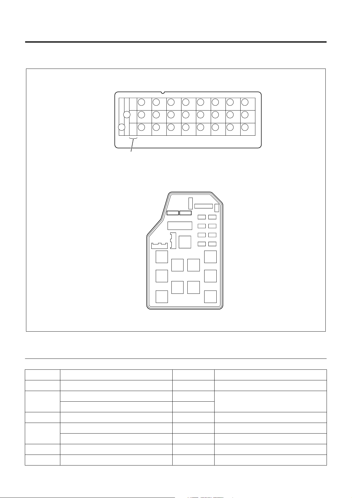
ECM Pinouts
ECM is installed in the c en ter c onsol e an d it s i npu t and
output are made through 4 c onnectors of 26 pins, 16
pins, 12 pins and 22 pins respectively, 76 pins in total.
000000 - 0000
0000 24V
000000 0000
MADE IN JAP AN
Engine Control System 1A-29
1
2
3
Legend
1. Engine model, rated voltage
2. Denso parts No.
D13
12
13
25
26
D26
D1
D14
C8
C16
4
LNW21AMF000501
2. Isuzu parts No.
4. Fuel injection unit model
C1
C9
B6
B12
A11
B1
41151269110211312413514615716814115216317418519620721822923102411
1516171819202122
B7
71829310
A22
A1
34567891011
21
14 13 12
A12
No. Connected to No. Connected to
A1 EGR,EVRV A12 Intake throttle VSV
LNW21ASF000501
Page 32

1A-30 Engine Control System
No. Connected to No. Connected to
A2 Startar switch A13 Tech 2 communications (DLC)
A3 Key switch A14 Not used
A4 Not used A15 Accelator position signal output (A/T)
A5 Exhaust brake cut signal (A/T) A16 Exhaust brake cut signal (A/T)
A6 Cluch switch A17 P/N switch, neutral switch
A7 Not used A18 Not used
A8 Not used A19 Freezer switch
A9 Diagnostic switch (DLC) A20 Air conditioner switch
A10 Idle position switch A21 Exhaust brake switch
A11 Power system ground A22 Swirl control VSV
No. Connected to No. Connected to
B1 Not used B7 Stop lamp relay
B2 Warm-up switch B8 Q down (ASR)
B3 Exhaust brake operating signal B9 Exhaust brake answer signal (ASR)
B4 Not used B10 Tachometer output
B5 Crank position sensor (+) B11 Crank position sensor (–)
B6 Pump cam position sensor (+) B12 Pump cam position sensor (–)
No. Connected to No. Connected to
C1 Coolant temperature sensor (+) C9 Intake air pressure
C2 Not used C10 Idle up volume
C3 Sensor power (AP, PTO accelerator, Idle up
volume)
C4 Sensor power (MAP) C12 Fuel temperature sensor (+)
C5 Sensor ground (MAP, coolant temp., intake
temp., fuel temp.)
C6 Sensor ground (AP, PTO accelerator, Idle up
volume)
C7 Not used C15 Intake temperature sensor (+)
C8 Not used C16 Not used
C11 Accelerator position sensor signal
C13 Not used
C14 PTO position sensor signal
No. Connected to No. Connected to
D1 Not used D14 Not used
D2 Not used D15 Not used
D3 Pump ROM communications D16 EDU fail signal input
D4 Exhaust brake VSV1 D17 Pump ROM communications
D5 Not used D18 Not used
Page 33

Engine Control System 1A-31
No. Connected to No. Connected to
D6 Accelerator position signal output (ASR) D19 Exhaust brake indicator lamp
D7 Vehicle speed sensor signal D20 Injection output signal (EDU)
D8 Not used D21 CHEK ENGINE lamp
D9 Main relay D22 Glow indicator lamp
D10 Spill control valve relay D23 Glow relay
D11 Not used D24 Battery power
D12 Timing control valve D25 Not used
D13 Signal ground D26 Power system ground
Strategy-Based Diagnostics
Strategy-Based System Diagnostics
The system diag nostic is a unifo rm approach to repai r
all electrical/electronic (E/E) systems. In the E/E
system, different from genera l vehicle problems, faults
frequently occur along the steps shown as follows:
1. Initial stage:
• A single fault occurs for a short while and,
therefore, the customer may miss it. In this
stage, the customer complaint is unclear and
the fault cannot be reprod uced. But, the ECM
may have stored the fault.
= Past fault
2. Middle stage:
• A single fault occurs for a short while but is
observed intermittent ly. It always occurs und er
certain conditions. The customer complaint
(description of fault) is clear but fault
occurrence conditions are unidentified. If you
comprehend these conditions, you can
reproduce the trouble.
= Intermittent fault (intermittent)
3. Realistic fault:
• The fault occurs certainly and the customer
complaint is realistic and clear. You can
reproduce the fault. However, there may exist
two or more causes.
= Current fault
The diagnostic flow c an always be used to resol ve an
E/E system problem and is a starting point when
repairs are necessar y. Th e following steps will inst ruct
the technician how to proceed with a diagnosis:
1. Verify the customer complaint:
• To verify the customer complaint, the technician
should know the normal operation of the
system.
2. Perform preliminary checks:
• Conduct a thorough visual inspection.
• Review the service history.
• Detecting unusual sounds or odors.
• Gather DTC (diagnostic trouble code)
information using Tech 2
3. Check bulletins and other servic e information.
4. Refer to “Symptom Diagnosis Chart” in this
manual.
• “Symptom Diagnosis Chart” contain information
on a system that may n ot be support ed by one
or more DTCs. “Symptom Diagnosis Chart”
verify proper operation of the system. This will
lead the technician in an organized approach to
diagnostics.
5. Refer to related descriptions such as those for
engine mechanicals.
DTC Stored
Follow the designated DTC chart exactly to make an
effective repair.
No DTC
Select the symptom from the “Symptom Diagnosis
Chart”. Follow to the diagnostic paths or suggestions to
complete the repair. You may refer to the applicable
components/system check in the functional check.
No Matching Symptom
1. Analyze the complaint.
2. Develop a plan for diagnostics.
3. Utilize the wiring diagrams and the theory of
operation.
Call technical as si st anc e for s im il ar c as es wh er e repair
history may be available. Combine technician
knowledge with efficient use of the available service
information.
Intermittents
Conditions that are not always present are call
intermittents. To resolve intermittents, perform the
following steps.
1. Observe history DTCs, DTC modes, and engine
data.
2. Evaluate the symptoms and the condition
described by the customer.
Page 34

1A-32 Engine Control System
3. Use a check sheet or othe r method to identify the
circuit or electrical system component.
No Trouble Found
This condition exists when the vehicles is found to
operate normally. The condition described by the
customer may be normal. Verify the customer
complaint against another vehicle that is operating
normally. The condition may be interm ittent. Verify the
complaint under the conditions described by the
customer before releasing the vehicle.
1. Reexamine the complaint.
When the compl aint cannot be suc cessfully found
or isolated, a re-evaluation is necessary. The
complaint should be re-verified and could be
intermittent as defin ed in Inter mittents, or c ould be
normal.
No. Item Objective Method
2. Repair and verify.
After isolating the cause, the repairs should be
made. Validate for proper operation and verify that
the symptom has been corrected. This may involve
road testing or other methods to verify that the
complaint has been resolved under the following
conditions:
• Conditions noted by the customer.
• If a DTC was diagnosed, verify a repair by
duplicating conditions present when the DTC
was set as noted by Tech 2 data.
Verifying Vehi cle Repair
When the electronic con trol syste m has been re paired,
it is necessary to verify the repa ir is appropriate. If the
repair is incomplete , the CHECK ENGINE Lam p (MIL)
may be lit again while the vehicle is released, or the
drivability may be impaired. Particularly for the
intermittents, it is necessary to reproduce the trouble
under the same conditi ons described by the custo mer
and check the trouble is no longer found.
1 Verifying the
DTC
2 Verifying the idle
speed after
warm-up
3 Verifying Tech 2
data list
4 Verifying the
restartability
5 Verifying the
electromagnetic
compatibility of
strong electric
wave emission
equipment
To check the DTC is not set
after the repair.
To check the idle control is
normally performed.
To provide basic checking for
engine control and
communication con di tio ns .
To check the start control
correctly works.
To check electric wave
emission equipment such as
transceiver, if added, does not
emit interfering waves.
Clear the previous DTC. Sufficiently warm up the
engine under idling, and increase the engine
speed to 2200 rpm and provide racing to verify
the test conditions.
Upon completion of engine warm-up, verify the
idle speed is 580 rpm for a manual transmission
vehicle or 650 rpm for an automatic transmission
vehicle with the air conditioner turned off. If a fault
is detected, refer to "Instable idling" in "
“Symptom Diagnosis Chart" to identify the cause.
Monitor Tech 2 data list and examine the data
using typical value sheet. Check typical values in
Tech 2 data list.
Upon completion of engine warm-up, verify the
cranking time is not more than 5 seconds and the
engine speed is stable after startup.
Turn on and off the electric wave emission
equipment, such as transceiver, to check whether
idle speed will change. If a problem is found,
inform the customer that the electric wave
emission equipment must be dislocated or
changing the power is needed.
Supplementary d escription about strong electric wa ve
emission equipment: If a problem is found in this
checking, provide the following advices to the
customer.
• To install the antenna away from the vehicle
electronic system components such as control unit
and sensor s as far as possible.
• To install the antenna cord at least 20 cm away
from the vehicle electronic system components
such as control unit and sensors.
• Do not arrange the antenna cord together with
other cables. In additi on, isolate the antenna cord
from other cables as far as possible.
• Install additional devices certainly according to
respective instruction manuals.
• Do not install high-power mobile communication
equipment.
Page 35

Engine Control System 1A-33
CAUTION:
Follow the steps below when you verify repairs on
OBD systems. Failure to follow these steps could
result in unnecessary repairs.
1. Review and record Tech 2 data relative to the
issued DTC.
2. Clear the DTC(s).
3. Operate the vehicl e while che cking t he associ ated
Tech 2 data.
Non-OEM Parts
All of the OBD diagnostic s have been calib rated to run
with OEM parts. There fore, installation of general onmarket sensors or switches are will result in incorrect
OBD diagnostics and CHECK ENGINE Lamp (MIL)
activation.
If on-market electroni c de vices such as mobile phon es ,
stereos, and theft deterrent system are improperly
installed, EMI (electromagnetic interference) radiation
occurs and affects the control system. As a result,
incorrect data are sent from sensors to turn on the
CHECK ENGINE Lamp (MIL). To diagnose the vehicle
with the OBD system, turn off or remove all the onmarket parts.
Poor Vehicle Maintenance
The sensitivity of OBD diagnostics will cause the
CHECK ENGINE Lamp (MIL) to turn on if the ve hi cl e is
not maintained properly. Restricted oil filters, fuel filters,
and crankcase deposi ts due to lack of oil changes or
improper oil viscosity can trigger actual vehicle faults
that were not previously monitored prior to OBD
diagnostics. Vehicle maintenance cannot be classified
as "non-vehicle fault", but with the sensitivity of OBD
diagnostics, vehic le maintenance schedules mu st be
more closely followed.
Related System Faults
Many of OBD system diagnostics will not run if the
ECM detects a fault on a related system or component.
Visual/Physical Engine Compartment Inspection
Perform a carefu l visual/physical engine co mpartment
inspection when perfo rming dia gnostic pro cedure. Th is
can often lead repairing a problem without further
steps. Use the followi ng guidelines when per forming a
visual/physical inspection.
• Inspect all vacuum hoses for punches, cuts,
disconnects, and co rrec t rout in g.
• Inspect hoses that ar e difficult to see be hind other
components.
• Inspect all harnesses in the engine compartment
for proper connections, burned or chafed spots,
pinched harnesses, contact with sharp edges or
contact with hot exhaust manifolds or pipes.
Basic Knowledge of Tools Required
IMPORTANT:
Lack of basic knowledge of this powertrain when
performing diagnostic procedures could result in
an incorrect diagnosis or damage to powertrain
components. Do not attempt to diagnose a
powertrain problem without this basic knowledge.
A basic understanding of hand tools, including
scan tool, is necessary to effectively use this
section of the Service Manual.
On-Board Diagnostic Tests
The diagnostic test is a series of steps, the result of
which is a pass or fail reported to the Diagnostic
Executive. When a diagnostic test reports a pass
result, the Diagnostic Executive records the following
data:
• The diagnostic test has been co mpleted sinc e the
last ignition cycle.
• The diagnostic tes t has passed durin g the current
ignition cycle.
• The fault identified by the diagnostic test is not
currently active.
When a diagnostic test reports a fail result, the
Diagnostic Executive records the following data:
• The diagnostic test has been co mpleted sinc e the
last ignition cycle.
• The fault identified by the diagnostic test is
currently active.
• The fault has been active during this ignition cycle.
• The operating conditions at the time of the failure.
Comprehensive Component Monitor Diagnostic
Operation
Comprehensive com ponent moni toring dia gnostics ar e
required to operate the engine properly.
Input Components
Input components are monitored for circuit continuity
and out-of-range values. This includes rationality
checking. Rationality checking refers to indicating a
fault when the signal from a sensor does not seem
reasonable, i.e., accele rator positi on sensor (AP S) that
indicates high throttle position at low engine loads or
low voltage MAP (manifold absolute pressure). Input
components may include, but are not limited to the
following sensors:
• Intake air temperature (IA T) sensor
• Crank position (CKP) sensor
• Engine coolant temperature (ECT) sensor
• Intake air pressure (MAP) sensor
• Accelerator position (AP) sensor
• Fuel temperature (FT) sensor
• Vehicle speed (VS) sensor
Page 36

1A-34 Engine Control System
Output Components
Output components are dia gno se d for pr ope r res pon se
to control module commands. Components where
functional monitoring is not feasible will be monitored
for circuit continuity and out-of-range values if
applicable. Output components to be monitored
include, but are not limited to, the following circuits:
•EGR EVRV
• Tra nsmission control
• Intake throttle
Terms Commonly Used in Diagnosis
Diagnostic
When used as a noun, the word diagnostic refers to
any on-board test run by the vehicle’s Diagnostic
Management System. A diagnostic i s simply a test r un
on a system or c omponent to determine if the system
or component is operating according to specification.
There are many diagnostics, shown in the following list.
• EGR (exhaust gas recirculation)
• Engine speed
• Vehicle speed
• ECT (engine coolant temperature)
• MAP (intake air pressure)
• VSV (Vaccum switching valve)
• IAT (intake air temperature)
• AP (accelerator position)
• FT (fuel temperature)
• Idle position switch
• Brake switch
by the diagnostic p rocedures c ontained in this manual.
The language of communicating the source of the
malfunction is a system of diagnostic trouble codes.
When a malfunction is detect ed by the control modul e,
a diagnostic trouble code is set and the CHECK
ENGINE Lamp (MIL) is illuminated.
Malfunction Indicator Lamp (MIL)
The malfunction indicator lamp (MIL) looks the same as
the MIL you are already familiar with ("Check Engine"
lamp).
Basically, the MIL is turned on when the electronic
control system s uch as ECM (engine control modu le)
fails and a DTC is detected.
Data Link Connector (DLC)
The provision of communication with the control
module is the data link connector (DLC). The DLC is
used to connect to Tech 2, or a scan tool. Some
common uses of Tech 2 are listed below.
• Identifying stored diagnostic trouble codes (DTCs)
• Clearing DTCs
• Performing output control tests
• Reading serial data
Diagnostic Executive
The Diagnostic Executive is a unique segment of
software that is designed to coordinate and prioritize
the diagnostic procedures as well as define the
protocol for recordin g and displaying their results. T he
main responsibilities of the Diagnostic Executive are
listed as following
• Commanding CHECK ENGINE Lamp (MIL) on and
off
• DTC logging and clearing
• Tech 2 data recording
• Acquiring current status information on each
diagnostic
Diagnostic Information
The diagnostic charts and functional checks are
designed to locate a faulty circuit or component through
a process of logi ca l d ec isio ns . T he ch ar ts ar e p re par ed
with the requirement that the vehicle functioned
correctly at the time of assembly and there are not
multiple faults present.
There is a continu ous self-diagnos is on certain co ntrol
functions. This diagnostic capability is complemented
87654321
161514131211109
LNW21ASH001801
Verifying Vehi cle Repair
Verification of vehicle repair will be more
comprehensive for vehicles with on-board diagnostic
(OBD) system diagnostic. Following a repair, the
technician should perform the following steps:
1. Review and record DTC diag nosed o r Tech 2 data
or both.
2. Clear DTC(s).
3. Operate the vehicle within the conditioned
described by Tech 2 data.
Page 37

4. Monitor the DTC st atus info rmation for the spec ific
DTC that has been diagnosed until the ECM
performs the diagnostic test associated with that
DTC.
Following these steps is very important in verifying
repairs OBD systems. Failure to follow these steps
could result in unnecessary repairs.
Diagnostic Trouble Code (DTC)
Whenever the starter switch is turned on, the ECM
executes self-testing for almost wirings and
components and, when detec ts a s ystem faul t, sto res i t
and enables backup co ntrol according to the DTC set.
When a fault occurs that will affect the running, the
ECM turns on the CHECK ENGINE Lamp (MIL) in the
meter panel or blinks the exhaust indicator lamp to
inform the driver of the fact.
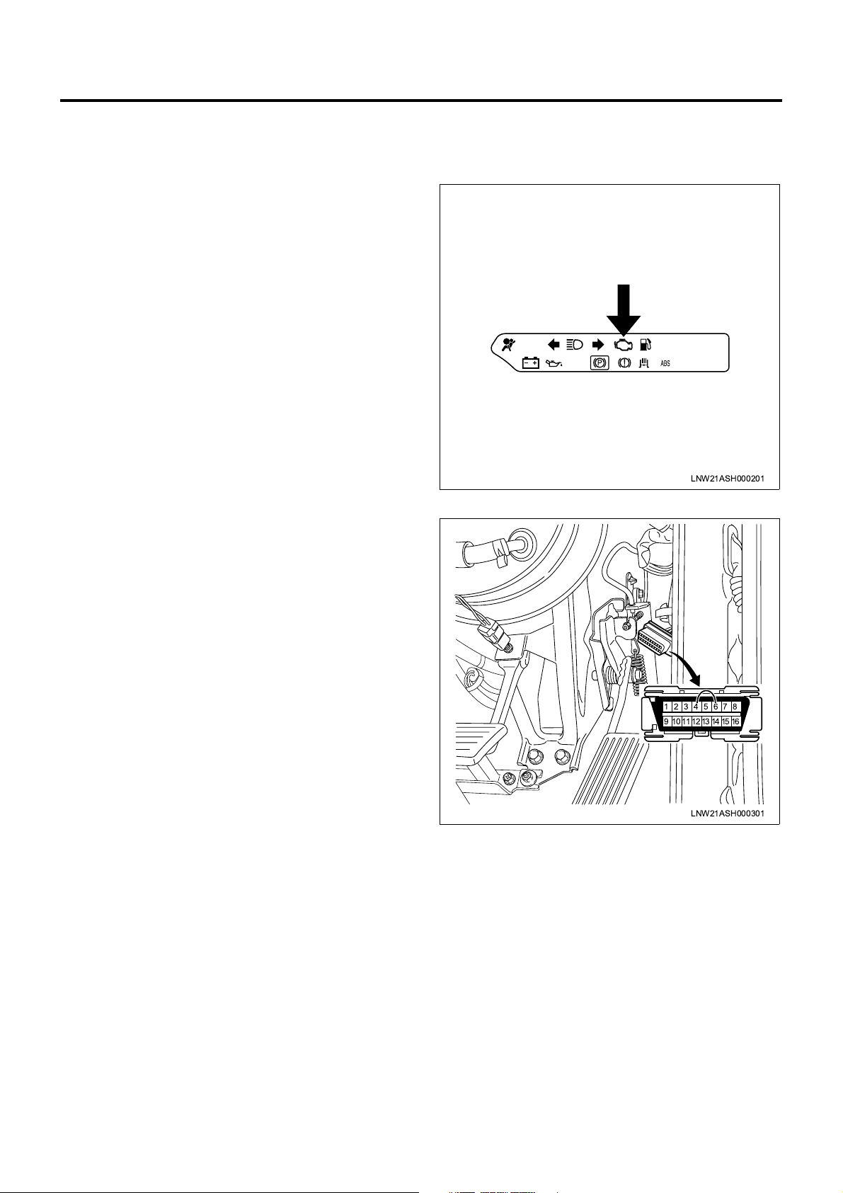
Reading Diagnostic Trouble Codes
Current and past DTCs stored to the ECM can be
visualized in the form of blinking CHECK ENGINE
Lamp (MIL) when the DLC (data link connector) is
shorted. To this end, provide the following steps.
1. Turn on the key switch and check the CHECK
ENGINE Lamp (MIL) is turned on. (Bulb check)
Engine Control System 1A-35
87654321
161514131211109
LNW21ASH000301
4. On the CHECK ENGINE Lamp (MIL), read the
number of blinks.
5. Identify the DTC from the DTC Chart.
Diagnostic Trouble Codes Not Stored
Code 12 that shows initiati on of i ndication is repeatedly
displayed.
LNW21ASH000201
2. Keep the key switch turned on and the engine
turned off.
3. Short pins 6 and 4 on the DLC. The DLC is a black
16-way connector and located at the lower right
corner of the instrument panel.
Page 38

1A-36 Engine Control System
Diagnostic Trouble Codes Stored
Code 12 that is displayed three times and then stored
code is displayed three ti mes. When multiple DTCs are
stored, each code is displayed three times, starting
from the lowest n umber. After all DTCs are displayed ,
above sequence is repeated from code 12 as l ong as
DLC is being shorted.
eg.,) Display Start Cord "12"
Display Start
Turn On
Turn Off
eg.,) Trouble Cord "21"
Display Start
Turn On
urn Off
0.4 0.4
0.4 0.4
3.2
1.2
3.23.2 1.2
3.2
Unit (sec)
Unit (sec)
eg.,1 : Diagnostic Trouble Codes not Stored
12 12 12 12 12 12 12 12 12 12 12 12 12 12 12
eg.,2 : Diagnostic Trouble Codes "21", "24" Stored
12 12 12 21 21 21 24 24 24 12 12 12 21 21 21
Clearing Diagnostic Trouble Codes
When the system fails and the DTC is stored to the
ECM, even repairing the faulty po rtion will not clea r the
DTC from the memory. To clear the DTC, conduct the
steps listed below.
• Keep the starter switch turned on and the engine
turned off.
• Short the data link connector.
Perform the following steps.
1. Turn off the idle position switch for not less than 1
second but n ot more than 3 seconds. (Pr ess the
accelerator pedal.)
2. Turn on the idle position sw itch for not le ss than 1
second but not more than 3 seconds. (Release the
4. Turn on the idle position switch for not less than 1
second but not more than 3 seconds. (Release the
accelerator pedal.)
5. Turn off the idle position swi tch for not le ss than 1
second but not more than 3 seconds. (Press the
accelerator pedal.)
6. After the above operations are properly completed,
the CHECK ENGINE L amp (MIL) illumi nates for 3
seconds to report the memory is cleared.
7. Turn off the starter switch. Wait for 5 seconds a nd
turn on the starter switch again.
When Tech 2 ha s been connected to the vehicle, the
DTC can be cleared through the memory clear
operation with Tech 2.
accelerator pedal.)
3. Turn off the idle position switch for not less than 1
second but n ot more than 3 seconds. (Pr ess the
accelerator pedal.)
Endless Display
Endless Display
LNW21AMF000601-X
Page 39

Engine Control System 1A-37
Functional Check List
Hearing The objective is to comprehend the symptom completely based on the
customer complaint and provide accurate diagnostic.
On-Board Diagnosti c Syst em
Check
Inactive CHECK ENGINE Lamp
(MIL) Check
Active CHECK ENGINE Lamp
(MIL) Check
The objective is to identify the faulty por tion on the electronic en gine control
system. (Checking proc edu re )
The objective is to check the CHECK ENGINE Lamp (MIL) when it is not
turned on even after ignition switch turn-on.
The objective is to check the C HECK ENGINE Lam p (MIL) is turn o n through
the DTC is not set while the engine running
Engine is crank but will not run The objective is to check the engine is not started though it is cranked by
turning the starter switch
Hearing Diagnostic
1. Using the Engine Control System Diagnostic
Chart, completely hear and comprehend the
customer complaint.
Reference:
Engine Control System Diagnostic Chart
When receiving the vehicle from the customer in the
service factory, you must verify both the symptom and
failure data using the Engine Control System
Diagnostic Chart.
Proceed the process by focusing on the po ssible
faulty system estimated from the fault (fact)
instead of random hearing.
2. Judge the failure information accurately.
1
Comprehend the situation concretely based on
5W1H principle.
Example: Low temperature, startup stage,
permanent generation, vicinity of engine, metallic
2
sound, etc.
Key points on hearing
• What • Faulty event
• When • Date and time, generation
frequency
• Where • Situation of road
• State • Running condition, driving
condition, weather conditions
• Result • Feeling of fault
LNW21ASH001301
Legend
1. Symptom
2. Failure generation frequency and conditions
t
The reason why this sheet is needed is as follows.
1. The symptom may not be reproduced in the
service factory.
2. The customer complaint is always not represent
failure.
3. If failure conditions are not i npu t to the respo n sibl e
technician correctly, unwanted repair man-hours
will be generated.
• The Engine Control System Diagnostic Chart helps
diagnostic, repair, and repair verification.
Page 40

1A-38 Engine Control System
Engine Control System Diagnostic Chart
Customer
Driver
Vehicle acceptance
date
Registration No.
No engine start
Poor startability
Instable idling
Poor driveability
SymptomFault conditions
Engine stall
Vibration at idling
Data observed at fault occurrence
Fault generation frequency
No cranking No initial combustion Incomplete initial combustion
Long cranking (6 seconds or more)
Others
Incorrect idle speed (idle speed enters into
typical range after warm-up)
Rough idling (idle speed deviates from
the typical range after warm-up)
Surging
Unusual sound
Immediately after engine startup
At operation of A/C
At gear shifting
Engine has transverse vibration and body has vertical vibration (engine’s vertical vibration is weaker than body’s
vibration)
Always
Others
Inspector:
Vehicle model and model
year
Vehicle ID
Engine model
Engine ID
Engine type
Odometer reading km
Unusual idle speed High ( rpm) Low ( rpm)
Others
Knocking Engine vibrationExtensive black/white smoke
Others
At release of accelerator pedal
Immediately after engine oil replacement
Others
OnceOccasionally (cycles: times/month)
Weather
Temperature 30
Place
Engine temperature
Driving conditions
Check Engine lamp
Past
DTC
Present
Fault history
Clear Cloudy Rainy Snowy Combined/
C or above
Highway Suburban area
Rough road
Cold
Startup
Driving
A/C SW ON/OFF
ON
Date (year/month/day)
Date (year/month/day)
Warm-up After warm-up Coolant temperature
C 10-15 C0C or below ( C)
20-30
Urban area Uphill slope Downhill slope
Others
Immediately after startup ( minutes) Idling Racing
Steady-speed driving Acceleration Deceleration
Others
Occasionally ON OFF
others
C Oil temperature C
LNW21AXF000701-X
Page 41

On-Board Diagnostic (OBD) System Check
Engine
Control
Module
(ECM)
1
2345678
9 10111213141516
0.5
GR/W
A9
Engine Control System 1A-39
A13
0.5
SB
Data Link
Connector
(DLC)
A/T SRS
Retarder
Circuit Description
The on-board diagnostic (OBD) system check is a
starting point for any driveability complaint diagnosis.
Before using this procedu re, perform a visual/physical
check the ECM (Engine Control Module) ground for
cleanliness and correct tightening.
The OBD system check is an orgainzed approach to
identifying a problem created by an electron ic engine
control system malfunction.
Diagnostic Aids
An intermitted may be caused by a poor conne ction, a
rubbed through wire in sulation, or a wire broke n inside
the insulator. Check for the poor connection or
damaged harness.
Inspect the ECM harness and connector fo r improper
mating, broken locks, improperly formed or damaged
pin, poor pin-to-wire connection, and damaged
harness.
LNW21ALF000901-X
Test description
Number(s) below refer to the step number(s) on the
Diagnostic Chart.
1. The CHECK ENGINE Lamp (MIL) should be “ON”
steady while the starter switch is “ON” and engine
“OFF”. If not “Inactive CHECK ENGINE Lamp (MIL)”
check should be used to isolate the malfunction.
2. Check the communic ation data circuit and ensure s
that the ECM is able to transmit serial data.
3. This test ensures that the ECM is capable of
controlling the CHECK ENGINE Lamp (MIL) and the
CHECK ENGINE Lamp (MIL) driver circuit is not
shorted to ground.
4. If the engine will no t start, the Cranks But Will Not
Run chart should be used to diagnose the condition.
7. A Tech 2 parameter that is not within the typical
range may help to isolate th e area that is causing the
problem.
Step Action V alue(s) Yes No
1. Starter switch "ON", and engine "OFF"
2. Observe the CHECK ENGINE Lamp
1
(MIL).
—
Go to "Inactive
CHECK ENGINE
Is the CHECK ENGINE Lamp (MIL) "ON"?
Go to Step 2
Lamp (MIL)”.
Page 42

1A-40 Engine Control System
Step Action V alue(s) Yes No
1. Starter switch "OFF"
2. Install the Tech 2.
3. Starter switch "ON".
2
4. Using Tech 2 , display ECM engine data.
—
Does the Tech 2 display engine data?
1. Remove the Tech 2 ,and short DLC (d ata
link connector) pins 4 and 6.
2. Observe the CHECK ENGINE Lamp
3
4
5
6
7
8
(MIL).
Does the CHECK ENGINE Lamp (MIL)
display "12"?
Start the engine.
Does the engine start and continue running?
Using Tech 2, select DTC.
Are any DTC stored?
Is DTC 52 stored ?
Compare ECM data v alues displayed on the
Tech 2 to the typical value engine scan data.
Are the displaye d values a standard or clo se
to the typical value?
1. Starter switch "OFF", disconnect the
ECM.
2. Starter switch "OFF", engine "OFF".
3. Check the communication data circuit for
an open wiring, short to ground, or short
to voltage. Also, check the DLC ignition
feed circuit for and open wiring or short to
ground and the DLC groun d circuit for an
open wiring.
4. If a problem is detected, repair as
necessary.
Go to Step 3 Go to Step 8
—
Go to Step 4
—
Go to Step 5
—
Go to Step 6 Go to Step 7
— Go to DTC 52
chart.
—
—
The OBD system
is in normal
condition
Go to “CHECK
ENGINE Lamp
(MIL) Remains
Active".
Go to "Engine
Cranks But Will
Not Run".
Go to the
appropriate DTC
Chart.
Refer to
"Diagnostic Aids"
Was a problem detected?
Check the Tech 2 with another vehicle.
9
Is the Tech 2 in abnormal?
Replace the ECM.
10
Is the action complete?
Repair Tech 2 or prep aration f or an other Tech
2.
11
Is the action complete?
Go to Step 2 Go to Step 9
—
Go to Step 11 Go to Step 10
—
Go to Step 2 —
—
Go to Step 2 —
Page 43

Inactive CHECK ENGINE Lamp (MIL)
Engine Control System 1A-41
Key
50A
3W
Meter Panel
Starter
SW
Glow Lamp
0.3O/L
D22 D21
3B/Y
Meter
15A
CHECK
ENGINE
Lamp
0.5Y/B
Engine Control Module (ECM)
Exhaust Brake
Lamp
0.3BR/W
D19
Circuit Description
The CHECK ENGINE Lamp (MIL) should be “ON”
steady while the sta rte r swi tc h (k ey swi tc h) is “ ON” and
engine “OFF”. The ignition powe r voltag e is applie d to
MIL through the meter fuse. ECM tur ns the MIL “ON”
by connecting the MIL driver circuit to the ground.
Diagnostic Aids
An intermittent MIL “OFF” may be caused by a poor
connection, rubbed-through wire insulation, or a wire
broken inside the insulation. Check the following items.
• Inspect the ECM harness and connector for
broken locks, improperly formed or dam aged pin,
poor pin-to-wire connection, and damaged
harness.
• When the engine is oper ating normally, c heck for
burning out of the bulb, open wiring of MIL output
circuit, or open wiring of the ignition power circuit.
LNW21ALF001001-X
• If the engine cranks but will not start, check for
open wiring of the ECM ignition ON power or
battery power circuit, or poor connection of the
ECM and engine ground.
Test Description
Number(s) below refer to the step number(s) on the
Diagnostic Chart.
2. If the “Inactive CHECK ENG IN E La mp ( M IL) wil l n ot
start, ECM ignition supply fault or bat tery power circuit
fault is considered.
9. Check each ECM ground pin with the test light
connected to B+ to see if the ground condition is
normal. For the pin pos iti on of the E CM gr ou nd ci rcui t,
refer to "ECM pin allocation".
Page 44

1A-42 Engine Control System
Step Action V alue(s) Yes No
Was the "On-Board Diagnosis (OBD) System
1
Check" performed?
Start the engine.
2
Is the engine start?
Check the meter fuse for the instrument
cluster ignition power circuit. (Meter 15A)
3
Is the fuse in normal condition?
Starter switch "ON". Connec t ground the test
light 5-8840-0632-0, and check the cluster
4
ignition power circuit.
—
—
—
—
Go to Step 2
Go to Step 3 Go to Step 7
Go to Step 4 Go to Step 17
Go to the "OBD
System Check"
Is the test light “ON”?
Check the bulb for meter clus ter and CHECK
ENGINE Lamp (MIL).
5
Replace the bulb if broken.
Was a problem detected?
1. Starter switch "OFF".
2. Disconnect ECM.
3. Connect the MIL driver c irc uit of the ECM
6
7
8
connector to the ground through a
jumper.
4. Starter switch "ON".
Is the malfunction indicator lamp (MIL) "ON"?
Check the ECM ignition power fuse, battery
power circuit fuse, engine fuse and ECM fuse.
Is the fuse in normal condition?
1. Starter switch "OFF".
2. Disconnect the ECM.
3. Starter switch "ON".
4. Connect ground the test light 5-88400607-0, and check the ignition power
circuit for the ECM harness connector.
Go to Step 5 Go to Step 14
—
Verify repair Go to Step 6
—
Go to Step 11 Go to Step 12
—
Go to Step 8 Go to Step 16
—
Is the test light “ON”?
Connect ground the test li ght 5-8840-0607-0,
and check the battery B+ power circuit for the
9
ECM harness connector.
Is the test light "ON"?
Check the ECM ground poor connection.
10
Was a problem detected?
Check the ECM pin for damage.
11
Was a problem detected?
Check the MIL driver circuit between ECM
and MIL for open wiring and poor connection.
12
Was a problem detected?
Go to Step 9 Go to Step 13
—
Go to Step 10 Go to Step 15
—
Verify repair Go to Step 11
—
Verify repair Go to Step 18
—
Verify repair Go to Step 19
Page 45

Engine Control System 1A-43
Step Action V alue(s) Yes No
Replace the "normal " relay for ECM main
relay.
13
Was the malfunction corrected?
Repair the ignition power circuit open wiring or
starter switch failure.
14
Is the repair complete?
Repair the ECM battery po wer cir cuit fo r o pen
wiring.
15
Is the repair complete?
Repair the ground short for ECM ignition
power circuit or ECM battery power circuit.
16
Is the repair complete?
Repair the ground s hort for i nstrument c luster
of ignition power circuit , and replace the fuse.
17
Is the action complete?
Replace the ECM.
18
Is the action complete?
Check the CHECK ENGINE Lamp (MIL)
driver circuit for the instrument panel poor
19
connection.
Was a problem detected?
—
—
—
—
—
—
—
Verify repair Go to Step 14
Verify repair —
Verify repair —
Verify repair —
Verify repair —
Verify repair —
Go to "Diagnostic
Verify repair
Aids"
Page 46

1A-44 Engine Control System
CHECK ENGINE Lamp (MIL) Remains Active
Key
50A
3W
Meter Panel
Starter
SW
Glow Lamp
0.3O/L
D22 D21
3B/Y
Meter
15A
CHECK
ENGINE
Lamp
0.5Y/B
Engine Control Module (ECM)
Exhaust Brake
Lamp
0.3BR/W
D19
Circuit Description
The CHECK ENGINE Lamp (MIL) should be “ON”
steady while the starte r s witc h (ke y s wit ch ) i s "ON" and
the engine “OFF”. The ignition power voltage is
supplied to MIL throu gh the meter fuse. E CM is turns
MIL "ON" by ground the MIL driver circuit.
If the DTC is not set up while the engine is running, MIL
does not keep ON. Wh en the engine is runni ng, DTC
has been set up, and the MIL ke eps ON, ground shor t
of the MIL driver circuit is considered.
Diagnostic Aids
An intermittent MIL “ON” may be caused by a poor
connection, rubbed-through wire insulation, or a wire
broken inside the insulation. Check the following items.
LNW21ALF001001-X
• Poor connection or damaged harness: Inspect the
ECM harness and connector for improperly
mating, broken locks, improperly formed or
damage pin, poor pin-to-wire connection, and
damaged harness.
Test Description
Number(s) below refer to the step number(s) on the
Diagnostic Chart.
2. If the MIL “ON” continue lighting when the ECM
disconnect, the MIL driver wiring is not faulty.
6. When the MIL driver circu it is norma l, the MIL dr iver
wiring in the meter panel cluster is faulty.
Page 47

Engine Control System 1A-45
Step Action V alue(s) Yes No
Was the "On-board diagnosis (OBD) system
1
check" performed?
1. Starter switch "OFF", disconnect the
ECM.
2. Starter switch "ON", and monitor the
2
CHECK ENGINE lamp (MIL).
—
—
Go to Step 2
Go to the "OBD
System Check"
Is the CHECK ENGINE Lamp (MIL) "ON"?
1. Starter switch "OFF", disconnect the
instrument panel connector.
2. Check for the ground short for MI L driver
3
4
5
6
circuit between ECM and instrument
panel cluster.
3. If a problem is detected, repair as
necessary.
Does the ground short for MIL driver circuit?
Replace the instrument panel cluster.
Is the action complete?
1. Starter switch "OFF", and re-connect the
ECM.
2. Short DLC 4 and 6. Starter switch "ON".
Does the CHECK ENGINE Lamp (MIL)
display DTC?
Replace the ECM.
Is the action complete?
—
—
—
—
Go to Step 3 Go to Step 5
Go to the "OBD
System Check" Go to Step 4
Go to the "OBD
System Check" —
Go to the "OBD
System Check" Go to Step 6
Go to the "OBD
System Check" —
Page 48

1A-46 Engine Control System
Engine Cranks But Will Not Run
1.25
Main Relay
W/R
EXH Brake
Magnetic Valve
SP Valve Relay
TCV
1.25
Y/R
D12
0.5
G/R
D10 D16 D20
0.5
L/R
Engine Control Module (ECM)
0.5
G/W
EDU
High Voltage
A
B
C
Generating
Circuit
Control
Circuit
EDU
SPV+
D
SPV
E
GND (Case)
F
SPV
Circuit Description
Fuel is injected by opening and closing the fuel high
pressure circuit wit h th e S PV (sp il l cont ro l v al ve). ED U
(engine driver uni t; high vo ltage driv er) is used to drive
the SPV at a high speed. EDU attains high speed drive
of SPV at a high fuel pressure with a high voltage,
quick energizing system. If the EDU, ECM or SPV
fails, the engine is crank but the initial explosion do es
not take place.
Diagnostic Aids
An intermittent problem may be caused by a poor
connection, rubbed-through wire insulation or a wire
broken inside the insulation. Check the following items.
C A B
D E F
LNW21ALF000801-X
• Poor connection or damaged harness: Inspect the
ECM harness and EDU harness connector for
improper mating, broken locks , improperly form ed
or damage pin, poor pin-to-wire connection, and
damaged harness.
Test Description
Number(s) below refer to the step number(s) on the
Diagnostic Chart.
4. An obvious cause of lo w fuel pressur e would be an
empty fuel tank.
9. In case of open wiring or short of the EDU circuit, set
DTC 53.
Page 49

Engine Control System 1A-47
Step Action V alue(s) Yes No
Was "On-board diagnosis (OBD) system
1
check" performed?
Check the 50A ECM f use, 50 A KEY SW fus e,
10A control fuse and the 15A control fuse.
2
Was the fuse blown?
Check for a short t o ground, and replace the
fuse.
3
Is the action complete?
Is the fuel tank empty?
4
Is a proper fuel used (use dehumidifying
5
agent is not advisable)?
Using Tech 2.
6
Set the DTC 11?
Using Tech 2.
7
Set the DTC 13?
Using Tech 2.
8
Set the DTC 16?
Using Tech 2.
9
Set the DTC 53? (Does the check for EDU
circuit defective?)
Using Tech 2.
10
Set the DTC 52?
1. Refer to engine mechanical diagnosis to
diagnose the following conditions.
• Faulty camshaft gear
• Leaking valve or ring
• Excessive valve deposits
• Weak valve spring
11
• Incorrect valve timing
• Leaking head gasket
• Excessive fuel filter deposits
2. If a problem is detected, r epair or replace
as necessary.
—
—
—
—
—
—
—
—
—
—
—
Go to Step 2
Go to Step 3 Go to Step 4
Verify repair —
Replenish to the
fuel tank Go to Step 5
Go to Step 6 Replace the fuel
Go to DTC 11 Go to Step 7
Go to DTC 13 Go to Step 8
Go to DTC 16 Go to Step 9
Go to DTC 53 Go to Step 10
Go to DTC 52 Go to Step 11
Go to the "OBD
System Check"
Was a problem detected?
Replace the ECM.
12
Is the action complete?
Verify repair Go to Step 12
—
Verify repair —
Page 50

1A-48 Engine Control System
Diagnosis with Tech 2 Scan Tool
T ech 2 Scan Tool
Tech 2 is an effective tool for diagnosis of electrical
failures on the engine co ntrol system. Thi s scan tool is
a small and lightweight handheld tester and, once
connected to the DLC on a vehicle, c omm uni cates with
the on-board ECM to per form various diagnostics and
tests.
1
2
4
Legend
1. PCMCIA card
2. Tech 2
Features of Tech 2
• Tech 2 (2) is operated at 12 V. Therefore, 24-V
power supply must n ot be used for this tool . If the
vehicle electrical system rating is 24 V, the adapter
must be connecte d t o a 1 2 V batte ry. Tech 2 mus t
not be powered by the cigarette lighter.
3
LNW21ALF000201
3. DLC cable
4. SAE 16/19-pin adapter
• Insert the PCMCIA card (1) into Tech 2. Then,
connect the DLC cable (3) and SAE 16/19-pin
adapter (4) to the VCI (vehicle communication
interface) of Tech 2 and connect Tech 2 to the DLC
on the vehicle.
• Insert or remove the PCMCIA card with the power
supply turned off.
Page 51

Engine Control System 1A-49
• Tech 2 supports two snapshot capacities.
• The PCMCIA card is susceptible to magnetism
and static electri city and, therefore, c omplete care
should be taken in handling.
• Tech 2 can plot snapshot graphs.
• Hitting the Exit key allows you to return to the main
menu at any time.
• To clear DTC(s), you should open the applic ation
menu and select "F1: Clear DTC Info" or "Clear
DTC".
Connection
1. I nsert the ISUZU System PCMCIA card into Tech
2.
2. Install the SAE 16/19-pin adapter to the DLC
cable.
3. Connect the DLC cable to Tech 2.
4. Check the starter switch is turned off.
5. C onnect the Tec h 2 SAE 16/19- pin adapter to the
DLC (data link connector = black) on the vehicle.
Connect Tech 2 and 12 V batter y with an adapter
cable.
LNW21ASH001401
• If the voltage is not applied to Tech 2, check the
3 A fuse.
6. Turn on the starter switch and press the PWR key
on Tech 2.
7. Check the following sc reen app ears on the Tec h 2
display.
87654321
161514131211109
LNW21ASH001801
Press (ENTER) To Continue
RUW16ESH001501-X
CAUTION:
Before inserting or removing the PCMCIA card,
always check the power is not applied to Tech 2.
Page 52

1A-50 Engine Control System
Operatin g Procedure
Press (ENTER) To Continue
(ENTER)
Vehicle Identification
Select one of the following
(N*) ELF, NPR, NQR, VFR
(ELF, NPR, NQR, VFR ENTER)
System Selection Menu
Main Menu
F0 : Diagnostics
F1 : Service Programming System
(SPS)
F2 : View Capture Data
F3 : Tool Options
F4 : Down load/Up load Help
(F0 ENTER)
Vehicle Identification
Select one of the following
Model Year(s)
(3)
2003
(2)
2002
(1)
2001
(Y)
2000
(X)
1999
(W)
1998
(2)
2002
(2002 ENTER)
(N*) ELF, NPR, NQR, VFR
F0 : Engine
F1 : Transmission
F2 : Chasis
F3 : Boody
(F0 ENTER)
Vehicle Identification
Select one of the following
Eingine
Denso 4H*
4JHI-TC Bosch
4HL1/4HJ1(COMMON RAIL)
4HL1/4HJ1(
Vehicle Interface Module
4HE1-TC (Diesel)
(4HL1/4HJ1(COMMON RAIL) or
4HL1/4HJ1(Vehicle Interface
Module) ENTER)
)
LNW21ALH000101-X
RUW16ELH000101-X
Menu List
• The list below shows what function is currently
used by the Tech 2 software.
F0: Diagnostic Trouble Codes
F0: Read DTC Info As Stored By ECU
F1: Clear DTC Information
F1: Data Display
F2: Snaphot
Page 53

Engine Control System 1A-51
Menu Breakdown
Diagnostic Trouble Codes
• When you find a DTC, go to the DTC Chart.
Diagnostic Trouble Codes
F0 : Read DTC Info As Stored By ECU
F1 : Clear DTC Information
LNW21ASH001501-X
The DTC is a lang uage allowing you to commun icate
with the on-board ECM. The DTC is coarsely divided
into two categories, past DTC and current DTC.
• Current DTC: A fault (failure) is displayed that is
found in the current ignition cycle.
• Past DTC: A fault (failure) is displayed that was
found in the last or past ignition cycle.
• Multiple DTC is generated when several troubles
(failures) occur. When multiple sensors or switches
share a ground, or an open wiring o r short occurs
on the shared power supply or ground, DTCs with
respect to related sensors or switches are
displayed. If several DTCs are displayed, it is
necessary to inspect the shared power supply or
ground for open wiring or short. Usin g DTC clear
mode erases the vehic le D TC info r mati on f rom the
ECM.
Data Display
• Typical values are described in the Tech 2 data
list.
Data Display
Battery Voltage
Accelerator Sensor
Turbo
Turbo
Intake Air Temperature
Fuel Temperature Sensor
Fuel Temperature
Battery Voltage
Select
Items
DTC
Quick
Snapshot
LNW21ASH009301-X
V
V
V
kPa
C
V
C
More
This menu displays the current data. The contents
synchronize with the vehicle status. For example, th e
engine coolant temperature sensor is monitored and
displayed on the screen an d, if the engi ne is idling, the
temperature on the screen will be changed accordingly.
• When you cannot select this data display menu:
A fault presents on the cable between ECM and
DLC.
• When an unusual value appears fixe d ly:
Example - If the engine coolant temperature
displayed is fixed to –40°C or +140°C, the possible
cause is faulty ECT sensor, open wiring, or short.
When moving conne ctors or wiring ha rnes ses with
hands changes the display, poor pin connection,
improper pin layout, broken harness wires, or short
is a cause and, therefore, repair is needed.
• When "✻" appears instead of value:
The Tech 2 software is faulty.
If even one asterisk is observed instead of data on
the display, the PCMCIA card needs version up.
Snapshot
• The snapshot mode records menus on the data list
and plots graphs.
• Using this mode, you can reproduce and record
customer’s claimed conditions and find faulty
engine data.
• You can replay the recorded data with the
commercial power applied to home outlets.
Page 54

1A-52 Engine Control System
• In the snapsho t after dete rminatio n of tri gger type ,
you can record the dat a ob tai ned whe n th e DT C is
displayed. Reviewing this data can reveal the
cause of failure.
Snapshot Plot
12345
ECT
Desired Idle Speed
Engine Speed
RUW16ESH001601
Snapshot After Data Indication
1. Select "Data Display" from the application menu.
2. A fter the vehicle data appears, select "Snapshot"
at the screen bottom.
3. After the elapse of some time, press the Exit key.
4. Th e screen changes. After "Continue" app ears at
the bottom, select "Continue".
5. After "Plot" appears at the bottom, select "Plot".
6. The menu select screen appears. Move to the
desired item and press the Enter key until three
items are select ed. Then, select "Approve" at the
bottom.
7. A graph is plotted on the screen.
Snapshot After Determination of Trigger Type
1. Select "Data Display" from the application menu.
2. After items appears on the screen, select the
desired item.
3. After the snapshot option screen appears,
determine the trigger type and select "Record
Snapshot" at the bottom.
4. When "Standby" blinks at the upper right of the
screen, select "Trigger" at the bottom.
5. Verify the trigger type.
6. The screen chang es. After "Continue" appea rs at
the bottom, select "Continue".
7. After "Plot" appears at the bottom, select "Plot".
8. The menu select screen appears. Move to the
desired item and press the Enter key until three
items are selec ted. Then, select "Approv e" at the
bottom.
9. A graph is plotted on the screen.
Replaying Recorded Data Graph
1. Turn on Tech 2 and select "Snapshot data"
displayed thereafter.
2. Check snapshot data titles appear on the screen.
3. Select the desired snapshot data title.
4. The data appears on the screen. To access the
graph, select "Plot" at the bottom.
5. Menu select scre en appears. Move to th e desired
item and press the Enter key until three items are
selected. Then, select "Approve" at the bottom.
6. The graph is plotted on the screen.
Te ch 2 Typical Data Values
The data list is used to check the condition of the
vehicle (engin e). The reference values (typic al values)
are compared to the data acquired from the actual
vehicle to determine the curren t situation, fo r example,
temporary or permanent deviation, so that you can
diagnose the vehicle (engine) and think out appropriate
repar plan. (The menu in y our Tech 2 may differ from
that shown above due to software version. Also, the
menu may be changed without prior notice.)
Tech 2 Data Display Unit
Typical value at idling. Complete
warm-up, air temperature 20°C
Battery Voltage V 23 ~ 26V
Accelerator Sensor V 0.41 ~ 0.45V
Turbo (MAP Sensor) V Depending on engine condition
Turbo (MAP) kPa Depending on engine condition
Intake Air Temperature °C Approx. 0 ~ 30°C depending on the
temperature around the engine.
Fuel Temperature Sensor V Approx. 2.35V depending on the
temperature around the engine.
Value at
diagnosis
Val ue after
check
Page 55

Engine Control System 1A-53
Tech 2 Data Display Unit
Typical value at idling. Complete
warm-up, air temperature 20°C
Fuel Temperature °C Depending on the temperature
around the engine.
Coolant Tempe ra ture Sens or V 1.38 ~ 1.68V
Coolant Temperature °C 80 ~ 100°C
PTO Sensor V 0V
Barometric Pressure V Approx. 3.3V
Idle-Up Sensor V Approx. 3.3 ~ 0.45V
Engine Speed rpm Approx. M/T: 580rpm, A/T : 650rpm
Final Accelerator Opening % 0%
PTO Accelerator Opening % 0%
Vehicle Speed km/h 0km/h
ASR Accelerator Opening % 100%
Corrected Fuel Injection Amount mm
Final Fuel Injection Amount mm
3
/stk Approx. 12.6mm3/stk
3
/stk Approx. 61.3mm3/stk
Target Rotation Speed rpm Approx. M/T: 580rpm, A/T : 650rpm
Value at
diagnosis
Val ue after
check
Fuel Spill Open Valve Angle °CA Approx. 92°CA
Fuel Spill Close Valve Angle °CA Approx. 56°CA
Fuel Injection Timing °CA 5°CA
Crank Angle Timing °CA 5°CA
TCV Duty Cycle % 50 ~ 60%
Cylinder 1 Compensation °CA ±1°CA or less
Cylinder 2 Compensation °CA ±1°CA or less
Cylinder 3 Compensation °CA ±1°CA or less
Cylinder 4 Compensation °CA ±1°CA or less
EGR Duty Cycle % Depending on engine condition
Starter Switch (S) On/Off Off
Neutral Switch On/Off Depending on the switch condition
Diagnostic Switch On/Off Depending on the switch condition
Key Switch (On) On/Off On
Idle Switch On/Off On
AC Switch On/Off Depending on the switch condition
Clutch Switch On/Off Depending on the switch condition
Exhaust Brake Switch On/Off Depending on the switch condition
Exhaust Brake (AT) Cutoff Switch On/Off Off
Exhaust brake (ASR) Cutoff
On/Off Off
Switch
PTO Switch On/Off Depending on the switch condition
Idle Speed Control On/Off On
Engine Stop Switch On/Off Off
Page 56

1A-54 Engine Control System
Tech 2 Data Display Unit
Typical value at idling. Complete
warm-up, air temperature 20°C
Value at
diagnosis
Val ue after
check
Engine Start On/Off Off
Accelerator Switch On/Off Off
Fuel Inj. Amount Limit (Injection) On/Off Off
TCV Feedback On/Off On
Thermo Switch On/Off Depending on the switch condition
Exhaust Press. Valve 1 On/Off Off
Glow Time Lamp On/Off Off
Glow Time Relay On/Off Off
Starting Counter (Counts) Varying depending on the count of
starter operations
Copy this table and use for measurement. • Typical value with starter switch ON (Engine
stops.)
Display on Tech 2 Unit
Typical value at idling. Complet e
warm-up, air temperature 20°C
Value at
diagnosis
Value after
confirmation
Battery Voltage V 23 ~ 26V
Accelerator Sensor V 0.41 ~ 0.45V
Turbo (MAP Sensor) V Depending on engine condition
Turbo (MAP) kPa Depending on engine condition
Intake Air Temperature °C Approx. 0 ~ 30°C depending on the
temperature around the engine.
Fuel Tempe ratur e Sensor V Approx. 2.39 V depe nding on t he
temperature around the engine.
Fuel Temperature °C Depending on the temperature
around the engine.
Coolant Temperature Sensor V 1.80 ~ 2.05V
Coolant Temperature °C 0 ~ 30°C
PTO Sensor V 0V
Barometric Pressure V Approx. 3.3V
Idle-Up Sensor V Approx. 3.3 ~ 0.45V
Engine Speed rpm 0rpm
Final Accelerator Opening % 0%
PTO Accelerator Opening % 0%
Vehicle Speed km/h 0km/h
ASR Accelerator Opening % 100%
Corrected Fuel Injection Amount mm
Final Fuel Injection Capacity mm
3
/stk —
3
/stk —
Target Rotation Speed rpm Approx. M/T: 580rpm, A/T : 650rpm
Fuel Spill Open Valve Angle °CA Approx. 83°CA
Fuel Spill Close Valve Angle °CA Approx. 56°CA
Page 57

Engine Control System 1A-55
Display on Tech 2 Unit
Fuel Injection Timing °CA 1°CA
Crank Angle Timing °CA 1°CA
TCV Duty Cycle % 0 ~ 1%
Cylinder 1 Compensation °CA ±1°CA or less
Cylinder 2 Compensation °CA ±1°CA or less
Cylinder 3 Compensation °CA ±1°CA or less
Cylinder 4 Compensation °CA ±1°CA or less
EGR Duty Cycle % Depending on engine condition
Starter Switch (S) On/Off Off
Neutral Switch On/Off Depending on the switch condition
Diagnostic Switch On/Off Depending on the switch condition
Key Switch (On) On/Off On
Idle Switch On/Off On
AC Switch On/Of f Depending on the switch condition
Clutch Switch On/Off Depending on the switch condition
Typical value at idling. Complet e
warm-up, air temperature 20°C
Value at
diagnosis
Value after
confirmation
Exhaust Brake Switch On/Off Depending on the switch condition
Exhaust Brake (AT) Cutoff Switch On/Off Off
Exhaust Brake (ASR) Cutoff
Switch
PTO Switch On/Off Depending on the switch condition
Idle Speed C ontrol On/Off On
Engine Stop Switch On/Off Off
Engine Start On/Off Off
Accelerator Switch On/Off Off
Fuel Inj. Amount Limit (Injection) On/Off Off
TCV Feedback On/Off On
Thermo Switch On/Off Depending on the switch condition
Exhaust Press. Valve 1 On/Off Off
Glow Time Lamp On/Off Off
Glow Time Relay On/Off Off
Starting Counter (Counts) Varying depending on the count of
On/Off Off
starter operations
Copy this table and use it for measurement. Typical
values with the starte r switch ON may vary dep ending
on the previous operating conditions.
Display on Tech 2 Unit
Battery Voltage V 23 ~ 26V
Accelerator Sensor V 1.52 ~ 1.55V
Typical value at idling. Complet e
warm-up, air temperature 20°C
• Typical value at 1500rpm
Value at
diagnosis
Value after
confirmation
Page 58

1A-56 Engine Control System
Display on Tech 2 Unit
Typical value at idling. Complet e
warm-up, air temperature 20°C
Turbo (MAP Sensor) V Depending on engine condition
Turbo (MAP) kPa Depending on engine condition
Intake Air Temperature °C Approx. 0 ~ 30°C depending on the
temperature around the engine.
Fuel Tempe ratur e Sens or V Approx. 2.35V dependi ng on the
temperature around the engine.
Fuel Temperature °C Depending on the temperature
around the engine.
Coolant Temperature Sensor V 1.38 ~ 1.68V
Coolant Temperature °C 80 ~ 100°C
PTO Sensor V 0V
Barometric Pressure V Approx. 3.3V
Idle-Up Sensor V Approx. 3.3 ~ 0.45V
Engine Speed rpm Approx. 1500rpm
Final Accelerator Opening % 25%
PTO Accelerator Opening % 0%
Value at
diagnosis
Value after
confirmation
Vehicle Speed km/h 0km/h
ASR Accelerator Opening % 100%
Corrected Fuel Injection Amount mm
Final Fuel Injection Amount mm
3
/stk —
3
/stk —
Target Rotation Speed rpm Approx. M/T: 580rpm, A/T : 650rpm
Fuel Spill Open Valve Angle °CA Approx. 90°CA
Fuel Spill Close Valve Angle °CA Approx. 56°CA
Fuel Injection Timing °CA 11°CA
Crank Angle Timing °CA 11°CA
TCV Duty Cycle % 60 ~ 70%
Cylinder 1 Compensation °CA ±1°CA or less
Cylinder 2 Compensation °CA ±1°CA or less
Cylinder 3 Compensation °CA ±1°CA or less
Cylinder 4 Compensation °CA ±1°CA or less
EGR Duty Cycle % Depending on engine condition
Starter Switch On/Off Off
Neutral Switch On/Off Depending on the switch condition
Diagnostic Switch On/Off Depending on the switch condition
Key Switch On/Off On
Idle Switch On/Off Off
AC Switch On/Of f Depending on the switch condition
Clutch Switch On/Off Depending on the switch condition
Exhaust Brake Switch On/Off Depending on the switch condition
Page 59

Engine Control System 1A-57
Display on Tech 2 Unit
Exhaust Brake (AT) Cutoff On/Off Off
Exhaust Brake (ASR) Cutoff On/Off Off
PTO Switch On/Off Depending on the switch condition
Idle Speed C ontrol On/Off On
Engine Stop Switch On/Off Off
Engine Start On/Off Off
Accelerator Switch On/Off Off
Fuel Inj. Amount Limit (Injection) On/Off Off
TCV Feedback On/Off On
Thermo Switch On/Off Depending on the switch condition
Exhaust Press. Valve 1 On/Off Off
Glow Time Lamp On/Off Off
Glow Time Relay On/Off Off
Starting Counter (Counts) Varying depending on the count of
Typical value at idling. Complet e
warm-up, air temperature 20°C
starter operations
Value at
diagnosis
Value after
confirmation
Copy this table and use it for measurement. Typical
values at 1500rpm may vary depending on conditions.
Page 60

1A-58 Engine Control System
T ech 2 Data Description
Item Tech 2 Data Display Unit Description How to use parameters
1/52 Battery Voltage V Indicates voltage applied to
ECM. Difference from the
actual battery voltage may be
caused due to loads in the
circuit, slight resistance value
at the harness or conne ctor pin
or other causes.
2/52 Accelerator Sensor V Indicates a signal value from
the accelerator position (AP)
sensor. ECM reads the signal
from AP sensor and indicates
it. Voltage is applied from ECM
to the AP sensor and ECM
reads the accelerator pedal
opening from varying sensor
signal.
3/52 Turbo
(Intake Air Pressure
Sensor)
V Indicates the signal value of the
intake air pressure (MAP).
Voltage from ECM is applied to
the MAP sensor and ECM
reads the intake air pressure
from varying signal of the
sensor and indicates that
value.
When the difference from the
actual battery voltage is
significant, any accessory
attached to the circuit is
considered as a cause, which
may have droppe d the vol tage.
If the value is out of the
standard range, circuit,
connector, connector mating, or
ECM may have some fault.
When the value of the AP
sensor (pedal opening)
becomes out of the standard
value according to the
accelerator pedal stepping
stroke, some fault has occurred
in the sensor, circuit, throttle
valve or ECM. Check the
sensor, circuit, accelerator
pedal and ECM in such a case.
If the signal value (pressure
display) from the sensor is out
of the standard value, some
fault has occurred in the
sensor, circuit or ECM. Check
the sensor, circuit or ECM in
such a case.
4/52 Turbo (Intake Air Pressure) kPa Voltage from ECM is applied to
the intake air pressure (MAP)
sensor and ECM reads the
intake air pressure from the
change of the sensor signal.
The signal read by ECM is
converted to pressure and
indicated.
5/52 Intake Air Temperature °C Indicates the intake air
temperature.
Using a thermistor type sensor
which is characterized by a
feature that the electric
resistance decreases with
increase of the intake air
temperature, voltage i s applied
from ECM to the IAT sensor,
and ECM receives signal from
the sensor, calculates and
indicates the result.
In the event of a fault oc curring
in the sensor or circuit, the
ECM performs failsafe by the
backup value.
If the signal value (pressure
display) from the sensor is out
of the standard value, some
fault has occurred in the
sensor, circuit or ECM. Check
the sensor, circuit or ECM in
such a case.
If the signal value (temperat ure
display) from the sensor is out
of the standard value, some
fault has occurred in the
sensor, circuit or ECM. Check
the sensor, circuit or ECM in
such a case.
Page 61

Engine Control System 1A-59
Item Tech 2 Data Display Unit Description How to use parameters
6/52 Fuel Temperature Sensor V Indicates the signal value of
fuel temperature sensor.
Voltage is applied from ECM to
the fuel temperature sensor
and ECM reads the fuel
temperature from the varying
sensor signal and indicates it.
7/52 Fuel Temperature °C Indicates the fuel temperature.
Using a thermistor type sensor
which is characterized by a
feature that the electric
resistance decreases with
increase of the fuel
temperature, voltage i s applied
from ECM to the fuel
temperature sensor, and ECM
receives signal from the
sensor, calculates and
indicates the result.
In the event of a fault oc curring
in the sensor or circuit, the
ECM performs failsafe by the
backup value.
8/52 Coolant Temperature
Sensor
V Indicates the signal value of the
coolant temperature sensor.
Voltage is applied from ECM to
the coolant temper ature sen sor
and ECM reads the engine
coolant temperature from the
varying sensor signal and
indicates it.
Various control conditions (at
start, low temperature, after
warm-up, etc.) are checked
based on the fuel tem perature.
May be used as con ditions for
DTC detection.
If the signal (temperature
display) from the sensor is out
of the standard value, some
fault has occurred in the
sensor, circuit or ECM. Check
the sensor, circuit or ECM in
such a case.
Various control conditions (at
start, low temperature, after
warm-up, etc.) are checked
based on the engine coolant
temperature. May b e used as
conditions for DTC detection.
9/52 Coolant Temperature °C Indicates engine coolant
temperature.
Using a thermistor type sensor
which is characterized by a
feature that the electric
resistance decreases with
increase of the coolant
temperature, voltage i s applied
from ECM to the coolant
temperature sensor, and ECM
receives signal from the
sensor, calculates and
indicates the result.
In the event of a fault oc curring
in the sensor or circuit, the
ECM performs failsafe by the
backup value.
If the signal value (temperat ure
display) from the sensor is out
of the standard value, some
fault has occurred in the
sensor, circuit or ECM. Check
the sensor, circuit or ECM in
such a case.
Page 62

1A-60 Engine Control System
Item Tech 2 Data Display Unit Description How to use parameters
10/52 PTO Sensor V Indicates the signal value of
PTO accelerator opening
sensor (all speed accelerator
sensor). ECM reads the s ignal
from the PTO accelerator
sensor and indicates. Voltage
from ECM is applied to the
sensor and ECM reads the
accelerator pedal ope ning from
the varying signal from the
sensor.
11/52 Barometric Pressure V Indicates signal value of the
barometric pressure sensor.
Voltage from ECM is applied to
the sensor installed in ECM
and ECM reads the varying
signal value and indicates it.
12/52 Idle Up Sensor V Indicates the signal value of the
idle up volume (idling speed
adjusting switch). Voltage from
ECM is applied to the sensor
and ECM adjusts the idling
speed based on the varying
signal.
If the value of the sens or is out
of the standard range
according to the accelerator
opening, some fault has
occurred in the sensor main
unit, circuit, throttle valve or
ECM. Check the sensor,
circuit, accelerator pedal or
ECM in such a case.
Various control conditions (fuel
injection amount control) are
checked based on the
barometric pressure.
If the signal value from the
sensor is out of the standard
value, some fault has occurred
in the sensor, circuit or ECM.
Check the sensor, circuit or
ECM in such a case.
If the signal from the am ount is
out of the standard range,
some fault has occurred in the
sensor, circuit, or ECM. Check
the sensor, circuit, or ECM in
such a case.
13/52 Engine Speed rpm Engine speed is calculated
based on the signal from the
NE censer and CKP sensor.
While the engine is idling, the
engine speed follows up the
target rotating speed and is
stabilized. The NE sens or and
CKP sensor generates
electromotive voltage by the
magnetic force and ECM
incorporates that voltage as a
signal.
14/52 Final Accelerator Opening % Indicates the accelerator pedal
opening. ECM reads the signal
from the AP sensor and
converts the signal read to
opening.
Use the engine speed data
comparing with the target
rotating speed, while the
engine is warming up and its
idling speed is sta ble as the air
conditioning system, etc. are
OFF. The engine speed
becomes stable around the
target rotating speed. When
the air conditioning system or
other load is applied, the
engine rotating speed is
changed but stabilized.
When the value of the AP
sensor (pedal opening)
becomes out of the standard
value according to the
accelerator pedal stepping
stroke, some fault has occurred
in the sensor, circuit, throttle
valve or ECM. Check the
sensor, circuit, throttle valve
and ECM in such a case.
Page 63

Engine Control System 1A-61
Item Tech 2 Data Display Unit Description How to use parameters
15/52 PTO Accelerator Opening % Indicates the opening of the
PTO accelerator. ECM reads
the signal from the PTO
accelerator sensor and
converts the signal read to
opening.
16/52 Vehicle Speed km/h ECM receives signal (pulse)
from the vehicle speed sensor,
calculates the vehicle speed
based on the signal and
indicates the result.
17/52 ASR Accelerator Opening % On a vehicle equipped with
ASR, when the ASR operates,
it controls the opening of the
accelerator to decrease the
engine speed. Indicates the
accelerator opening control
value. It is usually 100% and
decreases as the ASR
operates.
18/52 Corrected Fuel Injection
Amount
3
mm
/stk ECM cont rols the fuel injection
and correct the fuel injection
amount for each engine (fuel
amount necessary for
hipressurization). It indicates
fuel amount required to obtain
the target fuel pressure at the
time of injection depending on
the engine condition. ECM
indicates a value calculated
from the spill control valve,
engine speed, etc.
19/52 Final Fuel Injection Amount mm
3
/stk Indicates fuel injection amount
from the injector. ECU
calculated the amount of
pressurized fuel from the
condition of the timing control
valve and spill control valve
and indicates the calculation
result.
If the signal value from the
sensor is out of the standard
value, some fault has occurred
in the sensor, circuit or ECM.
Check the sensor, circuit or
ECM in such a case.
If the indication is different fro m
the reading on the speedometer, or if the indication does
not change, any fault ma y be i n
the vehicle speed sensor,
circuit or ECM.
If the value does not change,
poor communicati on with ABS/
ASR control unit, ABS/ASR
failure system, faulty ECM or
ABS/ASR control unit, or fault
in the circuit is the cause.
Check them in such a case.
If the value is out of the
standard range, any fault is in
the spill control valve, vehicle
speed sensor, circuit or ECM.
Check the valve, sensor, circuit
and ECM.
If the value is out of the
standard range, any fault is in
the spill control valve, timing
control valve, vehicle speed
sensor or circuit or ECM.
Check the valves, sensor,
circuits and ECM.
20/52 Target Rotation Speed rpm Idle speed calculated and
indicated by ECM. ECM
corrects and c alculates t he idle
speed from the coolant
temperature or engine load and
indicates the result as the
specified idle speed.
If the required id le speed does
not stabilized, improper
installation of ECM or sensors
(improper mating of co nnector,
bent pin, etc.) or incorrect
signal of ECM o r sensors may
be considered. If the harness
does not stabilize when
vibration is given, fault of the
harness, floating of the ground
circuit, or poor connection of
the connector is considered.
Page 64

1A-62 Engine Control System
Item Tech 2 Data Display Unit Description How to use parameters
21/52 Fuel Spill Open Valve
Angle
22/52 Fuel Spin Close Valve
Angle
°CA Ind icates the valve open timing
when the spill control valve is
controlled. ECM opens or
closes the valve to obtain the
fuel pressure required for
injection and calculates and
indicates the timing from the
engine condition.
ECM calculates the various
timing of the engine based on
the signals from the CKP
sensor and NE sensor.
°CA Ind icates the va lve close t iming
when the spill control valve is
controlled. ECM opens or
closes the valve to obtain the
fuel pressure required for
injection and calculates and
indicates the timing from the
engine condition.
ECM calculates the various
timing of the engine based on
the signals from the CKP
sensor and NE sensor.
If the value is out of the
standard range, any fault is in
the timing control valve,
sensors or, circuit or ECM.
Check the valves, sensors,
circuits and ECM.
If the value is out of the
standard range, any fault is in
the timing control valve,
sensors or circuit or ECM.
Check the valves, sensors,
circuits and ECM.
23/52 Fuel Injection Timing °CA Indicates the valve opening
timing when the timing control
valve is controlled. ECM opens
or closes the valve to adjust the
injection timing and calculates
and indicates the timing from
the engine condition.
ECM calculates the target
injection timing based on the
signals from the accelerator
opening, CKP sensor and NE
sensor.
24/52 Crank Angle Timing °CA Indicates the actual fuel
injection timing.
ECM opens or closes the v alve
to adjust the injection timing
properly and calculates and
indicates the timing from the
engine condition (target
injection timing). ECM
calculates the actual timing
based on the signals from the
CKP sensor and NE sensor.
25/52 TCV Duty Cycle % Indicates signal (duty ratio) to
drive the timing control valve.
ECM changes the valve
opening or closing travel
according to the changes of the
signal voltage (duty ratio) to
adjust the proper injection
timing.
If the value is out of the
standard range, any fault is in
the timing control valve,
sensors or circuit or ECM.
Check the valves, sensors,
circuits and ECM.
If the value is out of the
standard range, any fault is in
the timing control valve,
sensors or circuits or ECM.
Check the valves, sensors,
circuits and ECM.
If the value is out of the
standard range, any fault is in
the timing control valve,
sensors or circuit or ECM.
Check the valves, sensors,
circuits and ECM.
Page 65

Engine Control System 1A-63
Item Tech 2 Data Display Unit Description How to use parameters
26/52 Cylinder 1 Compensation °CA Indicates adjustment of fuel
injection timing for each
cylinder.
As there are micro var iations in
mechanical parts such as
injectors, pumps and fuel
pipes, the ECM makes
correction based on various
timing and respective sensor
signals to stabilize the engine
speed.
27/52 Cylinder 2 Compensation °CA Indicates adjustment of fuel
injection timing for each
cylinder.
As there are micro var iations in
mechanical parts such as
injectors, pumps and fuel
pipes, the ECM makes
correction based on various
timing and respective sensor
signals to stabilize the engine
speed.
28/52 Cylinder 3 Compensation °CA Indicates adjustment of fuel
injection timing for each
cylinder.
As there are micro var iations in
mechanical parts such as
injectors, pumps and fuel
pipes, the ECM makes
correction based on various
timing and respective sensor
signals to stabilize the engine
speed.
If the value is out of the
standard range, any fault is in
the injector, pump, various
piping systems, sensors, or
circuits or ECM. Check the
engine mechanical parts,
valves, sensors, circuits and
ECM.
If the value is out of the
standard range, any fault is in
the injector, pump, various
piping systems, sensors, or
circuits or ECM. Check the
engine mechanical parts,
valves, sensors, circuits and
ECM.
If the value is out of the
standard range, any fault is in
the injector, pump, various
piping systems, sensors, or
circuits or ECM. Check the
engine mechanical parts,
valves, sensors, circuits and
ECM.
29/52 Cylinder 4 Compensation °CA Indicates adjustment of fuel
injection timing for each
cylinder.
As there are micro var iations in
mechanical parts such as
injectors, pumps and fuel
pipes, the ECM makes
correction based on various
timing and respective sensor
signals to stabilize the engine
speed.
30/52 EGR Duty Cycle % Indicates signal (duty ratio) to
drive the motor to operate the
EGR valve.
ECM changes the valve
opening or closing travel
according to the changes of the
signal voltage (duty ratio) to
adjust the proper ECM
operation.
If the value is out of the
standard range, any fault is in
the injector, pump, various
piping systems, sensors, or
circuits or ECM. Check the
engine mechanical parts,
valves, sensors, circuits and
ECM.
If the value is out of the
standard range, any fault is in
the EGR valve, sensors, or
circuits or ECM. Check the
valves, sensors, circuits and
ECM.
Page 66

1A-64 Engine Control System
Item Tech 2 Data Display Unit Description How to use parameters
31/52 Starter Switch On/Off Indicates the key switch is set
to the [S] position
[ON] is indicated while the
starter motor is running.
32/52 Neutral Switch On/Off Indicates the neutral switch
condition.
[ON] is indicated while the
neutral switch is ON.
33/52 Diagnostic Switch On/Off Indicates the diagnostic switch
(when pins of DLC are
connected). Indication is
turned [ON] when the pins of
DLC are connected.
34/52 Key Switch On/Off Indicates the indication when
the key switch is set to the [ON]
position.
When the key switch position is
[ON], the indication is [ON].
35/52 Idle Position Switch On/Off Indicates the signal value of the
switch installed to the
accelerator pedal.
Monitors the pedal position
mutually with the accelerator
pedal position sensor.
At idling, the indication is
turned [ON].
If the indication does not
change, any fault is in the
switch, circuit or ECM. Check
the switch, circuit and ECM in
such a case.
If the indication does not
change, any fault is in the
switch, circuit or ECM. Check
the switch, circuit and ECM in
such a case.
If the indication does not
change, any fault is in the
switch, circuit or ECM. Check
the DLC, circuit and ECM in
such a case.
If the indication does not
change, any fault is in the
switch, circuit or ECM. Check
the switch, circuit and ECM in
such a case.
If the indication does not
change, any fault is in the
switch, circuit or ECM. Check
the switch, circuit and ECM in
such a case.
36/52 AC Switch On/Off Indicates the condition of the
air conditioning switch.
When the air conditioning
switch is turned [ON], the
indication becomes [ON].
37/52 Clutch Switch On/Off Indicates the clutch switch
condition.
When the clutch switch is
turned [ON], the indication
becomes [ON].
38/52 Exhaust Brake Switch On/Off Indicates the condition of the
exhaust brake switch.
When the exhaust brake switch
is turned [ON], the indication
becomes [ON].
39/52 Exhaust Brake (AT) Cutoff
Switch
On/Off On a vehicle equipped w ith an
automatic transmission, when
the engine coolant t emperature
is low, the exhaust brake is
controlled and operated.
Condition at this time is
indicated. The indication is
usually [OFF].
If the indication does not
change, any fault is in the
switch, circuit or ECM. Check
the switch, circuit and ECM in
such a case.
If the indication does not
change, any fault is in the
switch, circuit or ECM. Check
the switch, circuit and ECM in
such a case.
If the indication does not
change, any fault is in the
switch, circuit or ECM. Check
the switch, circuit and ECM in
such a case.
If the value does not change,
poor communication with the
AT control unit, system failure
of AT, f aulty ECM or AT control
unit, or fault in the exhaust
brake or circuit is the cause.
Check them in such a case.
Page 67

Engine Control System 1A-65
Item Tech 2 Data Display Unit Description How to use parameters
40/52 Exhaust Brake (ASR)
Cutoff Switch
41/52 PTO Switch On/Off Indicates the condition of PTO
42/52 Idle Speed Control On/Off I nd icates the engine idling
43/52 Engine Stop Switch On/Off Indicates the engine stop
On/Off On the vehicle equipped with
ASR, when the ASR operates,
it controls the exhaust brake
and stops it. Condition at this
time is indicated. Us ually [O FF
is indicated, which is changed
to [ON] when ASR is operated.
switch. When the PTO switch
is turned [ON], t he indication is
turned [ON].
condition.
When ECM judges the engine
idling, the indication is turned
[ON].
condition.
When ECM determines engine
stop, the indication is turned
[ON].
If the value does not change,
improper communication with
ABS/ASR control unit, system
failure of ABS or ASR, faulty
ECM or ABS/ASR control unit,
or fault in the circuit is the
cause. Check them in such a
case.
If the indication does not
change, any fault is in the
switch, circuit or ECM. Check
the switch, circuit and ECM in
such a case.
When the indication does not
change, some fault is in the
various sensors (rotating
sensor system), idle position
switch, circuit or ECM. Check
the sensor, switch, circuit, and
ECM.
If the indication does not
change, any fault is in the
motor unit, circuit or ECM.
Check the motor unit, circuit
and ECM in such a case.
44/52 Engine Start On/Off Indicates the starter motor
operating condition.
While the starter motor is
operating, the indication is
[ON].
45/52 Accelerator Switch On/Off ECM uses it to know the
“Accelerator pedal opening
condition” for various controls
such as a starting control.
When the accelerator pedal
opening exceeds 50%, the
indication is turned [ON].
46/52 Fuel Inj. Amount Limit
(Injection)
47/52 TCV Feedback On/Off When the engine starts
On/Off Indicates limit of fuel injection.
When the fuel injection is
restricted by the failsafe
function due to failure, etc., the
indication is turned [ON].
rotating, TCV starts operating.
ECM monitors the operation of
TCV based on the signal from
TCV and [ON] is indicated
while the signal is being sent
from TCV.
If the indication does not
change, any fault is in the
switch, circuit or ECM. Check
the switch, circuit and ECM in
such a case.
If the indication does not
change according to the
accelerator pedal stepping
travel, some fault is in the
sensor, circuit, throttle valve or
ECM. Check the sensor,
circuit, accelerator pedal or
ECM in such a case.
If the indication turns to [ON],
failure has occurred in some
unit. Check DTC or oth er units
and repair.
If the indication does not
change, some fault is in the
timing control valve, se nsors or
circuits or ECM. Check the
valves, sensors, circuits and
ECM in such a case.
Page 68

1A-66 Engine Control System
Item Tech 2 Data Display Unit Description How to use parameters
48/52 Thermo Switch On/Off Indicates the condition of the
thermo switch which operates
QWS.
When the coolant temperature
is low, the thermo switch is
turned [ON] and operates
QWS.
49/52 Exhaust Press. Valve 1 On/Off Indicates the condition of VSV
which operates the exhaust
brake.
When VSV starts operation, the
indication is turned [ON].
50/52 Glow Time Lamp On/Off Indicates operating condition of
glow (QOS) lamp.
When the lamp illumina tes, the
indication is turned [ON].
51/52 Glow Time Relay On/Off Indicates operating condition of
the glow (QOS) relay.
When the relay starts
operation, the indication is
turned [ON].
52/52 Starting Counter —
(Counts)
Frequency of signals given to
the starter switch [S] is counted
and indicated.
If the indication does not
change, any fault is in the
switch, circuit or ECM. Check
the switch, circuit and ECM in
such a case.
If the indication does not
change, any fault is in the
switch, VSV, circuit or ECM.
Check the switch, VSV, circuit
and ECM in such a case.
If the indication does not
change, any fault is in the lamp,
circuit or ECM. Check the
lamp, circuit an d ECM i n such a
case.
If the indication does not
change, any fault is in the relay ,
circuit or ECM. Check the
relay, circuit and ECM in such a
case.
Check the frequency at the
time of maintenance of the
idling stop system.
(The display menu of Tech 2 may vary depending on
the version of th e Tech 2 software or may be subj ec ted
to modification without notice.)
Page 69

Diagnostic Chart
Engine Control System 1A-67
DTC
11 No Signal
13 Timing
Sensor actuator
(detection item)
Crank
Position
Sensor
(CKP
Sensor)
Control
V alve (TCV)
Fault
Connector
not
Connected,
Harness
Open
Wiring or
Short,
Failed
Main Unit
Judgment
criterion
CHECK ENGINE
lamp ON
Exhaust brake
lamp blinki ng
ON — When not CKP
signal is
detected during
4 continuous
broken tooth
judgment at the
idle speed.
ON — When the
injection timing
feedback is
controlled, after
complete
warm-up,
absolute value
of difference
between the
target TCV
advance and
actual TCV
advance is
more than
7°CA
continuously
for more than
20 seconds.
Failsafe Major fault Point inspected
Prohibition of
feedback
control.
Prohibition of
warm-up
system,
EGR, intake air
throttling.
Restricts the
output.
Prohibition of
warm-up
system, EGR,
intake air
throttling.
Restricts the
output.
Large knocking
sound, poor
driveability.
Large knocking
sound, poor
driveability.
Wire harness
and connector
(CKP signal
system), crank
position
sensor, ECM.
Wire harness
and connector
(TCV system),
timing control
valve, ECM,
fuel filter, fuel,
injection pump.
14 Pump ROM
Fault
ON — Fault of
communication
with pump
ROM.
Corrects using
data in
EEPROM until
communication
is completed.
Then there is
no data, no
correction is
made until
completion of
initial communication.
Restricts the
output.
Large knocking
sound, poor
driveability.
Wire harness
and connector
(pump ROM
system), pump
ROM, ECM.
Page 70

1A-68 Engine Control System
DTC
Sensor actuator
(detection item)
15 Pu mp Cam
Sensor (NE
Sensor)
Short Break
Fault
16 No Signal
(Open
Wiring)
From Pump
Cam
Sensor (NE
Sensor)
Connector
not
Connected,
Harness
Open
Wiring or
Short,
Failed
Main Unit
Judgment
criterion
CHECK ENGINE
lamp ON
Exhaust brake
lamp blinking
— — When the
engine speed
is more than
650rpm, pump
cam sensor
(NE) signal
fault is
detected more
then 10 times.
ON — No NE pulse is
entered at idle
speed in other
than starting
state. Or, after
the starter
switch turned
ON, no NE
pulse is
entered and
the ECM input
voltage
becomes
below 22V
even once, and
when the
starter switch
turned OFF,
the ECM input
voltage
exceeds 22V
even once.
Failsafe Major fault Point inspected
Engine stall Wire harness
and connector
(NE signal
system), NE
sensor, ECM.
Spill valve
relay OFF,
Timing control
valve ON/OFF,
Fixes the time.
Engine stall,
Cannot start.
Wire harness
and connector
(NE system),
NE sensor,
ECM.
21 Engine
Coolant
Temperature Sensor
(ECT
Sensor)
Fault
23 Intake Air
Temperature Sensor
(IAT
Sensor)
Fault
ON — When engine
coolant
temperature
sensor output
voltage more
than 4.9V
continues.
ON — When intake
air temperature
sensor output
voltage below
0.05V or
voltage over
4.95V
continues.
Controls using
set value of
coolant
temperature
(starter sw i tc h
ON: 20°C,
starter switch
OFF: 110°C)
Warm-up
system, EGR.
Controls using
the set value of
intake air
temperature
(25°C).
Idle stop
prohibited.
Faulty starting
in cold state,
poor
driveability.
Poor
driveability
Wire harness
and connector
(coolant
temperature
sensor
system),
coolant
temperature
sensor, ECM.
Wire harness
and connector
(intake air
temperature
sensor
system), intake
air temperature
sensor, ECM.
Page 71

Engine Control System 1A-69
DTC
Sensor actuator
(detection item)
24 Accelerator
Position
Sensor (AP)
High
Voltage,
Low
Voltage
25 No Signal
from
Vehicle
Speed
Sensor (VS
Sensor)
Connector
not
Connected,
Harness
Open
Wiring or
Short,
Failed
Main Unit
Judgment
criterion
CHECK ENGINE
lamp ON
Exhaust brake
lamp blinking
ON ON When
accelerator
position sensor
output voltage
below 0.1V or
over 4.85V
continues.
ON — When the
clutch and gear
are connected
(normal clutch
switch, neutral
sensor) and
engine speed
is over
2200rpm,
vehicle speed
is 0 km/h for
more than 5
seconds.
Failsafe Major fault Point inspected
Prohibits the
exhaust brake,
warm-up
system, EGR,
intake air
throttling,
controls the
Poor
driveability
Wire harness
and connector
(AP signal
system),
accelerator
position
sensor, ECM.
accelerator
opening to
restrict the
output, and fix
to 0% or 30%
(idle position
switch fixed to
OFF : 30%, idle
position switch
ON: 0%).
Warm-up
system
prohibited
Improper
speedometer
indication
Wire harness
and connector
(vehicle speed
sensor
system),
vehicle speed
sensor, ECM.
31 Idle Up
Volume
Fault
32 Intake Air
Pressure
Sensor
(MAP
Sensor)
Fault
— — When idle up
volume output
voltage below
0.2V or above
4.8V continues.
ON — When intake
air pressure
signal voltage
over 4.9V or
below 0.1V
detected for
more than 3
seconds.
Idle up control
prohibited
ECM continues
control using
the set value of
100kPa.
Poor
driveability
Poor
driveability
Wire harness
and connector
(idle up volume
signal system),
idle up volume,
ECM.
Intake air
pressure
sensor, intake
air sensor
circuit, ECM.
Page 72

1A-70 Engine Control System
DTC
Sensor actuator
34 Exhaust
Brake Open
Wiring Fault
35 Neutral
Switch (P/N
Switch)
Fault
36 Clutch
Switch Fault
(detection item)
Connector
not
Connected,
Harness
Open
Wiring or
Short,
Failed
Main Unit
Judgment
criterion
CHECK ENGINE
lamp ON
Exhaust brake
lamp blinking
ON ON When ECM
input voltage is
over 16V,
exhaust brake
VSV is ON at
idle speed,
when VSV
signal voltage
is LOW or VSV
is OFF, or
when VSV
signal voltage
at HI
continues.
ON ON If the neutral
switch is not
changed from
ON to OFF
when the
engine is
rotating more
than 60
seconds and
the vehicle
speed is over
80 km/h.
ON ON If the clutch
switch is not
changed from
ON or OFF, or
from OFF to
ON when the
engine is
rotating for
more than 180
seconds after
the engine
starts (M/T
vehicle).
Failsafe Major fault Point inspected
Prohibits the
exhaust brake
Poor
driveability
Exhaust brake
VSV circuit,
exhaust brake
VSV, main
relay, ECM.
Prohibits the
exhaust brake
and warm-up
system.
Poor
driveability
Neutral switch,
HSA,
instrument
panel, vehicle
speed sensor,
ECM.
Prohibits
exhaust brake
and warm-up
system.
Poor
driveability
Clutch switch,
HSA,
instrument
panel, vehicle
speed sensor,
ECM.
41 Fuel
Temperature Sensor
(F T Sensor)
Circuit
High
Voltage
ON — When output
voltage of fuel
temperature
sensor over
4.9V continues.
Controls using
the fuel
temperature
set value
(40°C).
Idle stop
prohibited.
Poor
driveability
Wire harness
and connector
(fuel
temperature
sensor
system), fuel
temperature
sensor, ECM.
Page 73

Engine Control System 1A-71
DTC
Sensor actuator
(detection item)
51 Atmospheric Pressure
Sensor Fault
CHECK ENGINE
lamp ON
Exhaust brake
ON — When output
Judgment
criterion
lamp blinking
voltage of
atmospheric
pressure
sensor under
1.9V or over
4.7V continues.
52 ECM CPU Fault — — When the ECM
input voltage is
over 22V and
starter switch is
OFF at the
initial stage.
Failsafe Major fault Point inspected
Controls using
the
Poor
driveability
Replace the
ECM.
atmospheric
pressure set
value (100
kPa).
Idle stop
prohibited.
Restricts the
limit
accelerator
Engine stall ECM, non
OEM parts,
etc.
opening to
below specified
value and
returns the limit
value
gradually.
Restricts the
output. Idle
stop prohibited.
ECM CPU Fault
(Diagnosis with SUBCPU in E CU)
— ECM High Integrated IC
Fault
53 Engine
Driver Unit
(EDU)
Fault
Connector
not
Connected,
Harness
Open
Wiring or
Short,
Failed
Main Unit
— — When
EEPROM
judges ECM
fault.
ON — When pulse
signal fault
continues in
ECU with the
starter switch
OFF, ECM
input voltage
over 22V
(faulty
EEPROM ).
ON — When ECU
fault and open
wiring of SPV
continues more
than 5 times.
SPV relay/glow
relay OFF.
Prohibits
injection
command on
EDU.
Exhaust brake
ON.
Idle stop
prohibited.
Restricts the
output.
Idle stop
prohibited.
SPV and SPV
relay OFF.
Prohibition of
injection
command to
EDU and
feedback
control.
Exhaust brake
ON, Idle stop
prohibited.
Engine stall ECM
Poor
ECM
driveability
Engine stall ECM, EDU,
spill valve
(SPV), spill
valve relay.
Page 74

1A-72 Engine Control System
DTC
Sensor actuator
(detection item)
55 Pu mp Unma tch
(Difference from ECM
Specifications)
65 Idle Position
Switch Fault
Connector
not
Connected,
Harness
Open
Wiring or
Short,
Failed
Main Unit
Judgment
criterion
CHECK ENGINE
lamp ON
Exhaust brake
lamp blinking
ON — When pump
ROM does not
conform with
ECM (normal
pump ROM)
ON ON Idle position
switch OFF
when the
accelerator
position sensor
output voltage
is under 0.6V,
or idle position
switch is ON
when the
accelerator
position sensor
output voltage
is over 1.0V for
more than 10
seconds but
the accelerator
position sensor
is normal.
Or when the
sensor output
voltage is out
of the specified
value range:
< AP sensor
adjustment
reference
voltage>
• Idle point:
0.43 ~ 0.73V
• WOT point:
4.10 ~ 4.70V
• Input voltage:
5V (idle
position switch
operating
voltage: 0.59 ~
0.79V).
Failsafe Major fault Point inspected
Restricts the
output.
Idle stop
Cannot start ECM (injection
pump
identification).
prohibited.
Restricts the
output.
Poor
driveability
Idle position
switch, ECM.
Prohibits the
exhaust brake
and warm-up
system.
Idle stop
prohibited.
Page 75

DTC11 - No Signal CKP Sensor
Engine Control System 1A-73
1.25 B/L
CKP
ROM
0.5
0.5
G/B
G/R
Engine Control Module (ECM)
Compensation ROM and NE Sensor are built in the Injection Pump
Sensor
0.5
W
B5
(+)
0.5
R
B11
()
Sensor
0.5
G
B6
(+)
NE
B12
()
0.5
L
D13D3D17
Circuit Description
CKP (crank position) sens or generates CKP reference
signal. While the crank shaft rotates once, a CKP
reference pulse is generated.
ECM calculates the engine speed and crankshaft
position using the CKP reference signal.
DTC 11 is set when ECM receives no pulse on the CKP
reference circuit.
Major Faulty Event
• Large knocking sound
• Poor driveability
Conditions for Setting the DTC
• While broken tooth judgment is carried out 4
continuous times at th e idle speed, not any CKP
signal is detected.
LNW21ALF000701-X
Action Taken when the DTC Sets
• ECM illuminates th e CHECK ENGINE La mp (MIL)
when DTC is set.
• Advance feedback control prohibited
• Warm-up system prohibited
• EGR prohibited
• Intake air throttle prohibited
• Output restricted
Conditions for Clearing MIL/DTC
When the system fails and the DTC is stored to the
ECM, even repairing the fau lty portio n will not cle ar the
DTC from the memory. To clear the DTC, conduct the
following steps.
• Keep the starter switch turned on and the engine is
not running.
• Short the data link connector.
Page 76

1A-74 Engine Control System
Perform the following steps.
1. Turn off the idl e position switch for n ot less than 1
second but n ot more than 3 seconds. (Pr ess the
accelerator pedal.)
2. Turn on the idle position switch fo r not less th an 1
second but not more than 3 seconds. (Release the
accelerator pedal.)
3. Turn off the idl e position switch for n ot less than 1
second but n ot more than 3 seconds. (Pr ess the
accelerator pedal.)
4. Turn on the idle position switch fo r not less th an 1
second but not more than 3 seconds. (Release the
accelerator pedal.)
5. Turn off the idl e position switch for n ot less than 1
second but n ot more than 3 seconds. (Pr ess the
accelerator pedal.)
Step Action Value(s) Yes No
Perform the "On-Board Diagnostic (OBD)
1
System Check.?
1. Review and record the failure records
information.
2. Clear DTC 11.
2
3. Start the engine and idling for 1 minute.
4. Observe DTC.
Was DTC 11 set up?
Check the CKP sensor is correctly installed. If
a problem, repair as necessary.
3
Was a problem detected?
Starter switch "OFF". Disconnect the ECM
connector and measure the resistance value
4
between CKP+ and CKP–.
6. After the above operations are properly completed,
the Check Engine Lamp (MIL) illuminates for 3
seconds to report the memory is cleared.
7. Turn off the key switch. Wait for 5 seconds and
turn on the starter switch again.
When Tech 2 ha s been connected to the vehicle, the
DTC can be cleared through the memory clear
operation with Tech 2.
Diagnostic Aids
An intermittent may be cause by a poor connection,
rubbed-through wire in sulation, or a wi re broken ins ide
the insulation. Check for the following conditions.
• Poor connection: Inspect the ECM harness and
connector for improper mating, broken locks,
improperly formed or damaged pin, and pin-to-wire
connection
• Damaged harness: Ch eck the wiring harness for
damage.
—
—
—
25Ω
Go to Step 2
Go to Step 3
Verify repair Go to Step 4
Go to "OBD
System Check"
"Diagnostic Aids"
Refer to
Is the value normal?
Remove the CKP sensor connector. Measure
the resistance value between pins of the
5
sensor.
Is the value normal?
Repair the open wiring or poor connection of
between ECM and CKP.
6
Is the repair complete?
Replace the CKP sensor.
7
Is the action complete?
Check the CKP s ensor circuit for +B short or
ground short. If a problem, repair as
8
necessary.
Was a problem?
Go to Step 8 Go to Step 5
25Ω
Go to Step 6 Go to Step 7
—
Verify repair —
—
Verify repair —
—
Verify repair Go to Step 9
Page 77

Engine Control System 1A-75
Step Action Value(s) Yes No
Remove the CKP sensor. Turn the
crankshaft, and check from the CKP sensor
installing hole f or damage of the poi nter. If a
9
problem, repair as necessary.
—
Was a problem?
Check the ECM connecter pin for fault.
If a problem, repair as necessary.
10
Was a problem?
Replace the ECM.
11
Is the action complete?
DTC13 - TCV Fault
1.25
Main Relay
W/R
EXH Brake
Magnetic Valve
SP Valve Relay
Verify repair Go to Step 10
—
Verify repair Go to Step 11
—
Verify repair —
EDU
High Voltage
A
Generating
Circuit
D
SPV+
TCV
1.25
Y/R
D12
0.5
G/R
D10 D16 D20
0.5
L/R
Engine Control Module (ECM)
0.5
G/W
B
C
Control
Circuit
EDU
C A B
SPV
E
GND (Case)
F
D E F
LNW21ALF000801-X
SPV
Page 78

1A-76 Engine Control System
Circuit Description
Timing control valve (TCV) is installed to the injection
pump. Electric signal fr om ECM opens or closes the
fuel passage between the high pressure chamber and
low pressure chamber of the timer piston. When
current flows to the coil, the stator core becomes an
electromagnet, which co ntracts the spring, the m oving
core is absorbed and the fuel passage is opened.
ECM controls the TCV (duty control) and controls the
fuel injection start timing.
DTC 13 is set up when the target advance is
remarkably different from the actual advance.
Major Faulty Event
• Large knocking sound
• Poor driveability
Conditions for Setting the DTC
• At the injection timing feedback, after complete
warm-up, absolute value of difference more than
7°CA between the target TCV advance an d actual
TCV advance has continued for more than 20
seconds.
6. After the above operations are properly completed,
the Check Engine Lamp (MIL) illuminates for 3
seconds to report the memory is cleared.
7. Turn off the key switch. Wait for 5 seconds and
turn on the starter switch again.
When Tech 2 ha s been connected to the vehicle, the
DTC can be cleared through the memory clear
operation with Tech 2.
Diagnostic Aids
Check for the following conditions.
• Poor connection at the ECM: Inspect harness
connectors for bac ked-out pins, improp er mating,
broken locks, imprope rly formed or dama ged pins,
and poor pin-to-wire connection.
• Damaged harness: Ch eck the wiring harness for
damage.
Action Taken when the DTC Sets
• When any failure is detected first time, ECM
illuminates the CHECK ENGINE Lamp (MIL).
• Warm-up system, EGR and intake a ir throttle are
prohibited.
• Output is restricted.
Condition for Clearing the MIL/DTC
When the system fails and the DTC is stored to the
ECM, even repairing the faulty po rtion will not clea r the
DTC from the memory. To clear the DTC, conduct the
following steps.
• Keep the starter switch turned on and the engine is
not running.
• Short the data link connector.
Perform the following steps.
1. Turn off the idl e position switch for n ot less than 1
second but n ot more than 3 seconds. (Pr ess the
accelerator pedal.)
2. Turn on the idle position switch fo r not less th an 1
second but not more than 3 seconds. (Release the
accelerator pedal.)
3. Turn off the idl e position switch for n ot less than 1
second but n ot more than 3 seconds. (Pr ess the
accelerator pedal.)
4. Turn on the idle position switch fo r not less th an 1
second but not more than 3 seconds. (Release the
accelerator pedal.)
5. Turn off the idl e position switch for n ot less than 1
second but n ot more than 3 seconds. (Pr ess the
accelerator pedal.)
Page 79

Engine Control System 1A-77
Step Action Value(s) Yes No
Perform the "On-Board Diagnostic (OBD)
1
System Check.?
1. Review and record the failure records
information.
2. Clear DTC 13.
3. Start the engine, and run the idling until
2
3
the coolant temperature increases above
60°C.
4. Observe the DTC.
Set the DTC 13?
1. Starter switch “OFF”.
2. Disconnect the TCV.
3. Check for open wiring or ground short
between TCV connector and ECM
harness connector a nd between the TCV
connector and power source.
4. If a problem is detected, repair as
necessary.
—
—
—
Go to Step 2
Go to Step 3
Go to "OBD
System Check"
Refer to
"Diagnostic Aids"
Was a problem detected?
Check the connecti on at T CV a nd repla ce the
pin as necessary.
4
Was replacement of pin required?
Check the connection at ECM and replace the
pin if required.
5
Was the replacement of the pin required?
Measure the resistance value between the
TCV connecter pins
6
Is the value normal?
Check the timing gear installing condition.
If a problem is detected, repair as necessary.
7
Was a problem detected?
Replace the injection pump
8
Was DTC 13 set up after the step?
Replace the ECM.
9
Is the action complete?
Verify repair Go to Step 4
—
Verify repair Go to Step 5
—
Verify repair Go to Step 6
45Ω
Go to Step 7 Go to Step 8
—
Verify repair Go to Step 9
—
Verify repair Go to Step 9
—
Verify repair —
Page 80

1A-78 Engine Control System
DTC14 - Pump ROM Fault
1.25 B/L
CKP
ROM
0.5
0.5
G/B
G/R
Engine Control Module (ECM)
Compensation ROM and NE Sensor are built in the Injection Pump
Sensor
0.5
W
B5
(+)
0.5
R
B11
()
Sensor
0.5
G
B6
(+)
NE
B12
()
0.5
L
D13D3D17
Circuit Description
Pump ROM corrects discrepancy of injection amount
and injection timing caused by discrepancy of
correlation between the NE (pump cam) signal and
injection wavefo rm, precisely for each injection p ump.
NE signal is detected by the NE sensor and used to
control the injection amount, injection timing and idle
speed.
ECM controls the inj ection amou nt and injecti on timing
based on the signal from th e pump ROM, CKP sens or
and NE sensor. DTC 14 is set up when communication
fault is caused with the pump ROM.
Major Faulty Event
• Poor driveability
LNW21ALF000701-X
Conditions for Setting the DTC
• When Fault is caused in the communication with
the pump ROM when data is being received.
Action Taken when the DTC Sets
• When DTC is set, ECM illuminates the CHECK
ENGINE Lamp (MIL).
• ECM continues control using the set value.
• Output is restricted.
Conditions for Clearing MIL/DTC
When the system fails and the DTC is stored to the
ECM, even repairing the fau lty portio n will not cle ar the
DTC from the memory. To clear the DTC, conduct the
following steps.
• Keep the starter switch turned on and the engine is
not running.
Page 81

Engine Control System 1A-79
• Short the data link connector.
Perform the following steps.
1. Turn off the idl e position switch for n ot less than 1
second but n ot more than 3 seconds. (Pr ess the
accelerator pedal.)
2. Turn on the idle position switch fo r not less th an 1
second but not more than 3 seconds. (Release the
accelerator pedal.)
3. Turn off the idl e position switch for n ot less than 1
second but n ot more than 3 seconds. (Pr ess the
accelerator pedal.)
4. Turn on the idle position switch fo r not less th an 1
second but not more than 3 seconds. (Release the
accelerator pedal.)
5. Turn off the idl e position switch for n ot less than 1
second but n ot more than 3 seconds. (Pr ess the
accelerator pedal.)
6. After the above operations are properly completed,
Step Action Value(s) Yes No
Perform the "On-Board Diagnostic (OBD)
1
System Check.?
1. Review and record the failure records
information.
2. Clear DTC 14.
3. Start the engine, an d run the idling for 5
2
3
minutes.
4. Observe the DTC.
Set the DTC 14?
1. Starter switch "OFF".
2. Disconnect the pump ROM.
3. Check the pump ROM circuit between the
pump ROM connecto r and ECM harnes s
connector for open wiring or ground
short.
4. Check for open wiring between the pump
ROM connector and ground.
5. If a problem is detected, repair as
necessary.
the Check Engine Lamp (MIL) illuminates for 3
seconds to report the memory is cleared.
7. Turn off the key switch. Wait for 5 seconds and
turn on the starter switch again.
When Tech 2 ha s been connected to the vehicle, the
DTC can be cleared through the memory clear
operation with Tech 2.
Diagnostic Aids
An intermittent may because by a poor connection,
rubbed-through wire in sulation, or a wi re broken ins ide
the insulation. Check for the following conditions.
• Poor connection: Inspect the ECM harness and
connector for improper mating, broken locks,
improperly formed or damaged pin, and pin-to-wire
connection
• Damaged harness: Ch eck the wiring harness for
damage.
—
—
—
Go to Step 2
Go to Step 3
Go to "OBD
System Check"
"Diagnostic Aids"
Refer to
Was a problem detected?
Check the connection at the pu mp ROM and
replace the pin as necessary.
4
Was the replacement of the pin required?
Check the connection at ECM and replace the
pin as necessary.
5
Was replacement of the pin required?
Replace the injection pump.
6
Set the DTC14 after completion of the step?
Replace the ECM.
7
Is the action complete?
Verify repair Go to Step 4
—
Verify repair Go to Step 5
—
Verify repair Go to Step 6
—
Verify repair Go to Step 7
—
Verify repair —
Page 82

1A-80 Engine Control System
DTC15 - Pump Cam Sensor (NE Sensor) Short Break Fault
1.25 B/L
CKP
ROM
0.5
0.5
G/B
G/R
Engine Control Module (ECM)
Compensation ROM and NE Sensor are built in the Injection Pump
Sensor
0.5
W
B5
(+)
0.5
R
B11
()
Sensor
0.5
G
B6
(+)
NE
B12
()
0.5
L
D13D3D17
Circuit Description
The NE (pump cam) sensor generates NE signal. ECM
determines the injection amount and injection timing
using the NE signal and starts the fuel injection.
DTC 15 is set up when the number of pulses on the NE
standard circuit received by ECM is not proper.
Major Fault Event
• Engine stall
Conditions for Setting the DTC
NE signal Fault arose m ore than 10 times dete ct when
the engine speed is more than 650rpm.
Action Taken when the DTC Sets
• If any failure is detected, the CHECK ENGINE
Lamp (MIL) is kept ON (not blinking). (DTC is
checked by Tech 2 or diagnosis switch.)
LNW21ALF000701-X
Conditions for Clearing MIL/DTC
When the system fails and the DTC is stored to the
ECM, even repairing the fau lty portio n will not cle ar the
DTC from the memory. To clear the DTC, conduct the
following steps.
• Keep the starter switch turned on and the engine is
not running.
• Short the data link connector.
Perform the following steps.
1. Turn off the idle position swi tch for not le ss than 1
second but not more than 3 seconds. (Press the
accelerator pedal.)
2. Turn on the idle position switch for not less than 1
second but not more than 3 seconds. (Release the
accelerator pedal.)
3. Turn off the idle position swi tch for not le ss than 1
second but not more than 3 seconds. (Press the
accelerator pedal.)
Page 83

Engine Control System 1A-81
4. Turn on the idle position switch fo r not less th an 1
second but not more than 3 seconds. (Release the
accelerator pedal.)
5. Turn off the idl e position switch for n ot less than 1
second but n ot more than 3 seconds. (Pr ess the
accelerator pedal.)
6. After the above operations are properly completed,
the Check Engine Lamp (MIL) illuminates for 3
seconds to report the memory is cleared.
7. Turn off the key switch. Wait for 5 seconds and
turn on the starter switch again.
When Tech 2 h as been connected to the vehicle, the
DTC can be cleared through the memory clear
operation with Tech 2.
Step Action Value(s) Yes No
Perform the "On-Board Diagnostic (OBD)
1
System Check.?
1. Review and record the failure records
information.
2. Clear DTC 15.
3. Start the engine and running within the
2
3
safety range.
4. Observe the DTC.
Set the DTC 15?
1. Starter switch "OFF".
2. Disconnect the NE sensor.
3. Check for open wiring, ground short or +B
short between the NE censor connector
and ECM connector.
4. If a problem is detected, repair as
necessary.
Diagnostic Aids
An intermittent may be cause by a poor connection,
rubbed-through wire in sulation, or a wi re broken ins ide
the insulation. Check for the following conditions.
• Poor connection: Inspect the ECM harness and
connector for improper mating, broken locks,
improperly formed or damaged pin, and pin-to-wire
connection
• Damaged harness: Ch eck the wiring harness for
damage.
Test Description
Number(s) below refer to the step number(s) on the
Diagnostic Chart.
2. Check for the presence of failure.
—
—
—
Go to Step 2
Go to Step 3
Go to "OBD
System Check"
"Diagnostic Aids"
Refer to
Was a problem detected?
Check the connection at the pu mp ROM and
replace the pin as necessary.
4
Was the replacement of the pin required?
Check the connection at ECM and replace the
pin as necessary.
5
Was replacement required?
Replace the injection pump.
6
Set the DTC15 after completion of the step?
Replace the ECM.
7
Is the action complete?
Verify repair Go to Step 4
—
Verify repair Go to Step 5
—
Verify repair Go to Step 6
—
Verify repair Go to Step 7
—
Verify repair —
Page 84

1A-82 Engine Control System
DTC16 - No Signal from Pump Cam Sensor (NE Sensor)
1.25 B/L
CKP
ROM
0.5
0.5
G/B
G/R
Engine Control Module (ECM)
Compensation ROM and NE Sensor are built in the Injection Pump
Sensor
0.5
W
B5
(+)
0.5
R
B11
()
Sensor
0.5
G
B6
(+)
NE
B12
()
0.5
L
D13D3D17
Circuit Description
The NE (pump cam) sensor generates NE signal. ECM
determines the injection amount and injection timing
using the NE signal and starts the fuel injection.
DTC 16 is set up when ECM does not receive NE
signal.
Major Faulty Conditions Fault Condition
• Engine stall
• Engine cannot start.
Conditions for Setting the DTC
• NE signal is not rece ived at the idle spe ed, excep t
for the starting.
• When all of the following conditions are met:
1. When the starter switch is turned ON, no NE signal
is received.
LNW21ALF000701-X
2. When the starter swit ch is turned ON, ECM input
voltage decreases below 22V even once.
3. When the starter switch i s turned OFF, ECM input
voltage increases over 22V even once.
Action Taken when DTC Sets
• When DTC is set, ECM illuminates the CHECK
ENGINE Lamp (MIL).
• Injection signal is stopped.
• Spill valve relay is turned OFF.
• Timing control valve ON/OFF time is fixed.
Conditions for Clearing MIL/DTC
When the system fails and the DTC is stored to the
ECM, even repairing the fau lty portio n will not cle ar the
DTC from the memory. To clear the DTC, conduct the
following steps.
Page 85

Engine Control System 1A-83
• Keep the starter switch turned on and the engine is
not running.
• Short the data link connector.
Perform the following steps.
1. Turn off the idl e position switch for n ot less than 1
second but n ot more than 3 seconds. (Pr ess the
accelerator pedal.)
2. Turn on the idle position switch fo r not less th an 1
second but not more than 3 seconds. (Release the
accelerator pedal.)
3. Turn off the idl e position switch for n ot less than 1
second but n ot more than 3 seconds. (Pr ess the
accelerator pedal.)
4. Turn on the idle position switch fo r not less th an 1
second but not more than 3 seconds. (Release the
accelerator pedal.)
5. Turn off the idl e position switch for n ot less than 1
second but n ot more than 3 seconds. (Pr ess the
accelerator pedal.)
6. After the above operations are properly completed,
the Check Engine Lamp (MIL) illuminates for 3
seconds to report the memory is cleared.
7. Turn off the key switch. Wait for 5 seconds and
turn on the starter switch again.
When Tech 2 ha s been connected to the vehicle, the
DTC can be cleared through the memory clear
operation with Tech 2.
Diagnostic Aids
An intermittent may be cause by a poor connection,
rubbed-through wire in sulation, or a wi re broken ins ide
the insulation. Check for the following conditions.
• Poor connection: Inspect the ECM harness and
connector for improper mating, broken locks,
improperly formed or damaged pin, and pin-to-wire
connection
• Damaged harness: Ch eck the wiring harness for
damage.
Test Description
Number(s) below refer to the step number(s) on the
Diagnostic Chart.
2. Check of the presence of failure.
Step Action Value(s) Yes No
Perform the "On-Board Diagnostic (OBD)
1
System Check.?
1. Review and record the failure records
information.
2. Clear DTC 16.
2
3. Crank the engine.
4. Observe the DTC.
Set the DTC 16?
1. Starter switch "OFF".
2. Disconnect the ECM.
3. Measure the resistance value between
3
NE+ and NE– pins of the ECM connector.
Is the value normal?
1. Starter switch "OFF".
2. Disconnect the NE sensor.
3. Measure the resistance value between
4
NE sensor connector pins.
Is the value normal?
Repair the open wiring or poor connection of
between ECM and NE sensor.
5
Is the repair complete?
Check for +B short or gro und short in the NE
sensor circuit. If a problem, repair as
6
necessary.
—
—
230Ω
230Ω
—
—
Go to Step 2
Go to Step 3
Go to Step 6 Go to Step 4
Go to Step 5 Go to Step 8
Verify repair —
Go to "OBD
System Check"
Refer to
"Diagnostic Aids"
Was a problem?
Verify repair Go to Step 7
Page 86

1A-84 Engine Control System
Step Action Value(s) Yes No
Check for fault in the ECM connecter pin.
If a problem, repair as necessary.
7
Was a problem?
—
Verify repair Go to Step 8
Replace the injection pump.
8
Was DTC16 setting cleard after the
replacement?
—
Verify repair Go to Step 9
Replace the ECM.
9
Is the action complete?
—
Verify repair —
DTC21 - ECT Sensor Fault
32 1
ECM
C-1 C-12 C-15 C-9 C-5
0.5
Y/G
0.3
0.5
BLU/
RED
W/
GRN
SIG
Engine Coolant
Temperature
Sensor
GND
0.3
0.5
R/G
W/
GRN
SIG
GND
Fuel Temperature
Sensor
0.3
0.5
R/Y
W/
GRN
SIG
Intake Air
Temperature
Sensor
GND
Sensor
Ground
0.5
W/
GRN
Intake Air
Pressure Sensor
C-4
0.5
L/W
Circuit Description
The ECT (engine coolant tempe rature) sensor is of the
thermistor type. Resistance value changes according
to the changes of the temperature. Resistance value is
smaller when the engi ne coolant temper ature is high er
and increases with th e decrease of the engine coolant
temperature.
LNW21ALF000601-X
ECM applies voltage of 5V to the ECT sensor through
the pull up resistance of the voltage. Engine coolant
temperature is detected based on the changes of
voltage. The voltage is decr eased when the resi stance
is small (the temperature is high) while increased when
the resistance is large (the temperature is low).
Page 87

Engine Control System 1A-85
DTC 21 will be set when the signal voltage is
excessively high or low.
Characteristics of Circuit
• Multiple DTC is generated when several troubles
(failures) occur. When multiple sensors or switches
share a ground, or an open wiring o r short occurs
on the share power sup ply or ground, DTCs with
respect to related sensors or switches are
displayed. If several DTCs are displayed, it is
necessary to inspect the shared power supply or
ground for open wiring or short.
The harness 1 in figure is a common ground for the
engine coolant temperature sensor, fuel
temperature senso r, intak e air temper ature sens or
, intake air pressure sensor and EGR position
sensor. In the event of the open wiring in wire 1,
DTC 21, 23, 41 and 32 are indicated at the same
time. In the event of the open wiring in wire 2, DTC
21, 23, and 41 are indica ted at the time. Like thi s,
the case where two or more DTC’s are displayed is
the multiple DTC.
• If multiple DTC21, 23, 41, and 32 are displayed,
the ground wire 1 must be checked.
• If multiple DTC21, 23, and 41 are displayed, the
ground wire 2 must be checked.
• If multiple DTC21 and 23 are displayed, the ground
wire 3 must be checked.
DTC Sensor actuator (detection item)
21 Engine coolant
temperature sensor
(ECT)
23 Intake air temperature
sensor
41 Fuel temperature sensor
32 Intake air pressure
sensor
Major Faulty Event
• Faulty starting in cold state
• Poor driveability
Conditions for Setting the DTC
• When coolant temperature output voltage over
4.9V has continued.
Connector not
connected, open
wiring or short of
harness, failure of
main unit
Conditions for Clearing MIL/DTC
When the system fails and the DTC is stored to the
ECM, even repairing the fau lty portio n will not cle ar the
DTC from the memory. To clear the DTC, conduct the
following steps.
• Keep the starter switch turned on and the engine is
not running.
• Short the data link connector.
Perform the following steps.
1. Turn off the idle position swi tch for not le ss than 1
second but not more than 3 seconds. (Press the
accelerator pedal.)
2. Turn on the idle position switch for not less than 1
second but not more than 3 seconds. (Release the
accelerator pedal.)
3. Turn off the idle position swi tch for not le ss than 1
second but not more than 3 seconds. (Press the
accelerator pedal.)
4. Turn on the idle position switch for not less than 1
second but not more than 3 seconds. (Release the
accelerator pedal.)
5. Turn off the idle position swi tch for not le ss than 1
second but not more than 3 seconds. (Press the
accelerator pedal.)
6. After the above operations are properly completed,
the Check Engine Lamp (MIL) illuminates for 3
seconds to report the memory is cleared.
7. Turn off the key switch. Wait for 5 seconds and
turn on the starter switch again.
When Tech 2 ha s been connected to the vehicle, the
DTC can be cleared through the memory clear
operation with Tech 2.
Diagnostic Aids
Check the following conditions.
• Poor connection at the ECM: Inspect harness
connectors for bac ked-out pins, improp er mating,
broken locks, imprope rly formed or dama ged pins,
and poor pin-to-wire connection.
• Damaged harness: Ch eck the wiring harness for
damage.
Test Description
Number(s) below refer to the step number(s) on the
Diagnostic Chart.
2. Check for the presence of failure.
3. If the repeat of DTC 21 is possible only by
reproducing the failure record condition, refer to the
table of "Temperature vs resistance value". ECT
sensor can be tested to check for deviation in the
sensor at various temperature using this table. If
deviation exists in the sensor, replace the ECT sensor.
When the ECT sensor is normal, the failure is an
intermittent operation.
Page 88

1A-86 Engine Control System
Engine Coolant Temperature Sensor
°C Ω
Temperature vs. resistance value
(approximate value)
20 2500
50 840
90 247
1. Immerse the temperature sensing part of the
sensor in the water and check the changing
resistance values changing the coolant
temperature.
[Thermistor Characteristics]
30
20
10
7.0
5.0
3.0
2.0
1.0
0.7
Resistance Value (k )
0.5
0.3
0.2
0.1
-20 1200 10020 8040 60
Engine Coolant Temperature ( C)
LNW21ASH000901-X
LNW21ASH002301
Step Action Value(s) Yes No
Was the "On-board diagnosis (OBD) system
1
check" performed?
—
Go to Step 2
Go to "OBD
System Check"
1. Starter switch "ON".
2. Using Tech 2, monitor the coolant
temperature sensor output voltage
2
display.
4.9V
Is the coolant temperature sensor output
voltage higher than specified value?
Go to Step 4 Go to Step 3
1. Starter switch "ON". Stop the engine.
2. Using Tech 2, monitor the DTC 21
3
Does Tech 2 display the DTC 21?
—
Refer to “Test
Description”
Refer to
"Diagnostic Aids"
Page 89

Engine Control System 1A-87
Step Action Value(s) Yes No
1. Disconnect the ECT sensor electric
connector.
2. Connect the ECT signal circuit and
sensor ground circuit through a jumper
4
5
6
7
with the ECT sensor harness connector.
3. Using Tech 2, monitor the coolant
temperature sensor output voltage
display.
Is the coolant temperature sensor output
voltage below specified value?
1. Connect the ECT signal circuit of the ECT
sensor harness connector through a
jumper to the chassis ground.
2. Using Tech 2, monitor the coolant
temperature sensor output voltage
display.
Is the coolant temperature sensor output
voltage specified value?
Check for poor conn ectio n on the ECT sensor
and replace the pin as necessary.
Was the replacement of the pin required?
1. Starter switch "ON".
2. Disconnect the ECM and chec k for open
wiring in the ECT sensor ground circuit.
3. If open wiring exists in the ECT sensor
ground circuit, repair as necessary.
0.05V
Go to Step 6 Go to Step 5
0.05V
Go to Step 7 Go to Step 8
—
Verify repair Go to Step 10
—
Was there open wiring in the ECT sensor
ground cir cuit?
1. Starter switch "ON".
2. Disconnect the ECM and chec k for open
wiring in the ECT signal circuit.
3. If open wiring exists in the ECT sensor
8
signal circuit, repair as necessary.
Was there open wiring in the ECT signal
circuit?
Check the ECM for poor connection of the
sensor ground pin or p oor connection of E CT
signal circuit pin and replace the pin as
9
necessary.
Was the replacement of the pin required?
Replace the ECT sensor.
10
Is the action complete?
Replace the ECM.
11
Is the action complete?
Verify repair Go to Step 9
—
Verify repair Go to Step 9
—
Verify repair Go to Step 11
—
Verify repair —
—
Verify repair —
Page 90

1A-88 Engine Control System
DCT23 - IAT Sensor Fault
32 1
ECM
C-1 C-12 C-15 C-9 C-5
0.5
Y/G
0.3
0.5
BLU/
RED
W/
GRN
SIG
Engine Coolant
Temperature
Sensor
GND
0.3
0.5
R/G
W/
GRN
SIG
GND
Fuel Temperature
Sensor
0.3
0.5
R/Y
W/
GRN
SIG
Intake Air
Temperature
Sensor
GND
Sensor
Ground
0.5
W/
GRN
Intake Air
Pressure Sensor
C-4
0.5
L/W
Circuit Description
IAT (intake air temperatu re) sensor is of the ther mistor
type. Resistance value changes according to the
changes of temperature . Resistance valu e is smaller
when the intake air temperature is higher and
increases with the decrease of the intake air
temperature.
ECM applies vol tage of 5V to the IAT sensor through
the pull up resistance. Intake air temperature is
detected based on the cha nges of voltage. The voltage
is decreased when the resistance is small (the
temperature is high) while increased when the
resistance is large (the temperature is low).
DTC 23 will be set when the signa l vo ltage ex cessi vely
high or excessivly low.
Characteristics of Circuit
• Multiple DTC is generated when several troubles
(failures) occur. When multiple sensors or switches
LNW21ALF000601-X
share a ground, or an open wiring or s hort occurs
on the share power su pply or ground, DTCs with
respect to related sensors or switches are
displayed. If several DTCs are displayed, it is
necessary to in spect the shared power supp ly or
ground for open wiring or short.
The harness 1 in above figure is a common ground
for the engine coolant temperature sensor, fuel
temperature sensor, intake air tempera ture sensor
, intake air pressure sensor and EGR position
sensor. In the event of the open wiring in wire 1,
DTC 21, 23, 41 and 32 are indica ted at the same
time. In the event of the open wiring in wire 2, DTC
21, 23, and 41 are indicate d at the time. Like this ,
the case where two or more DTC’s are displayed is
the multiple DTC.
• If multiple DTC21, 23, 41, and 32 are displayed,
the ground wire 1 must be checked.
Page 91

Engine Control System 1A-89
• If multiple DTC21, 23, and 41 are displayed, the
ground wire 2 must be checked.
• If multiple DTC21 and 23 are displayed, the ground
wire 3 must be checked.
DTC Sensor actuator (detection item)
21 Engine coolant
temperature sensor
(ECT)
23 Intake air temperature
sensor
41 Fuel temperature sensor
32 Intake air pressure
sensor
Major Faulty Event
• Poor driveability
Conditions for Setting the DTC
• When intake air tempe rature s ensor si gnal v oltage
over 4.95V or below 0.05V is detected.
Connector not
connected, open
wiring or short of
harness, failure of
main unit
4. Turn on the idle position switch for not less than 1
second but not more than 3 seconds. (Release the
accelerator pedal.)
5. Turn off the idle position swi tch for not le ss than 1
second but not more than 3 seconds. (Press the
accelerator pedal.)
6. After the above operations are properly completed,
the Check Engine Lamp (MIL) illuminates for 3
seconds to report the memory is cleared.
7. Turn off the key switch. Wait for 5 seconds and
turn on the starter switch again.
When Tech 2 ha s been connected to the vehicle, the
DTC can be cleared through the memory clear
operation with Tech 2.
Diagnostic Aids
Check the following conditions.
• Poor connection at the ECM: Inspect harness
connectors for bac ked-out pins, improp er mating,
broken locks, imprope rly formed or dama ged pins,
and poor pin-to-wire connection.
• Damaged harness: Ch eck the wiring harness for
damage.
Action Taken when the DTC Sets
• When DTC is set, ECM illuminates the CHECK
ENGINE Lamp (MIL).
• ECM continues to control using the set value.
(25 °C)
Condition for Clearing the MIL/DTC
• When the system fails and the DTC is stored to the
ECM, even repairing the faulty portion will not clear
the DTC from the memory. To clear the DTC,
conduct the following steps.
• Keep the starter switch turned on and the engine is
not running.
• Short the data link connector.
Perform the following steps.
1. Turn off the idl e position switch for n ot less than 1
second but n ot more than 3 seconds. (Pr ess the
accelerator pedal.)
2. Turn on the idle position switch fo r not less th an 1
second but not more than 3 seconds. (Release the
accelerator pedal.)
3. Turn off the idl e position switch for n ot less than 1
second but n ot more than 3 seconds. (Pr ess the
accelerator pedal.)
Test Description
Number(s) below refer to the step number(s) on the
Diagnostic Chart.
2. Check for the presence of failure.
3. If the repeat of DTC 23 is possible only by
reproducing the failure record condition, refer to the
table of "Temperature vs res ista nc e v alue" . IAT sensor
can be tested to check for deviation in the sensor at
various temperature using this table. If deviation exists
in the sensor, replace the IAT sensor. When the IAT
sensor is normal, the failure is an intermittent
operation.
Intake Air Temperature Sensor
°C Ω
Temperature vs. resistance value
(approximate value )
25 2796
15 4450
5 7280
Step Action Value(s) Yes No
Was the "On-board diagnosis (OBD) system
1
check" performed?
—
Go to Step 2
Go to "OBD
System Check"
Page 92

1A-90 Engine Control System
Step Action Value(s) Yes No
1. Starter switch "ON".
2. Using Tech 2, monitor the "IAT sensor
2
output voltage".
4.9V
Is the value larger than specified value?
1. Starter switch "ON".
2. Using Tech 2, monitor the "IAT sensor
3
4
5
6
output voltage".
Is the value below the specified value?
1. Remove the IAT sensor.
2. Using Tech 2, monitor the "IAT sensor
output voltage".
Is the value below the specified value?
1. Stop the engine.
2. Operate the vehicle under the failure
generating conditions.
3. Using Tech 2, monitor the DTC 23.
Does Tech 2 display the DTC 23?
1. Disconnect the IAT sensor connector.
2. Connect the signal circuit and ground
circuit through a jumper with the sensor
connector.
3. Using Tech 2, monitor the "IAT sensor
output voltage".
0.05V
0.05V
—
0.05V
Go to Step 6 Go to Step 3
Go to Step 4 Go to Step 5
Go to Step 8 Go to Step 13
Refer to “Test
Description”
Refer to
"Diagnostic Aids"
Is the value less than the specified value?
1. Connect the IAT sensor signal circuit
through a jumper to the chassis ground.
2. Using Tech 2, monitor the "IAT sensor
7
8
9
10
11
12
output voltage".
Is the value less than the specified value?
Check for fault in the IAT sensor pin
connector. If a problem, repair as necessary.
Was a problem?
Check the IAT sensor ground circuit for open
wiring. Repair as necessary.
Was open wiring?
Check the IAT signal circuit for open wiring.
Repair as necessary.
Was open wiring?
Check the IAT signal circuit for ground short.
Repair as necessary.
Was short?
Check the ECM connector pin for fault.
Replace the pin as necessary.
Was replacement of the pin required?
Go to Step 8 Go to Step 7
0.05V
Go to Step 9 Go to Step 10
—
Verify repair Go to Step 11
—
Verify repair Go to Step 12
—
Verify repair Go to Step 12
—
Verify repair Go to Step 12
—
Verify repair Go to Step 13
Page 93

Engine Control System 1A-91
Step Action Value(s) Yes No
Check the IAT sensor and if a problem,
replace it.
13
Was a problem?
—
Verify repair Go to Step 14
Replace the ECM.
14
Is the action complete?
—
Verify repair —
DTC24 - AP Sensor Output Fault
2 1
Engine Control Module
(ECM)
0.5
Y/B
C6
(Sensor
Ground)
PTO Accelerator Sensor
0.5
R/B
C14
Signal
AP (Accelerator Position) Sensor
Idle Up Volume
0.5
Y/G
C10
Signal
0.5
G/O
C11
Signal
0.5
Y/R
C3
(Sensor
Power)
Circuit Description
The AP (accelerat or position) sensor supplies voltage
signal which changes according to the accelerator
pedal angle to ECM.
ECM controls the injection amount and other items
using the AP signal.
DTC 24 will be set when the signal voltage is
excessively high or low.
LNW21ALF000501-X
Characteristics of Circuit
• Multiple DTC is generated when several trouble s
(failures) occur. When multiple sensors or switches
share a ground, or an open wiring or s hort occurs
on the share power su pply or ground, DTCs with
respect to related sensors or switches are
displayed. If several DTCs are displayed, it is
necessary to in spect the shared power supp ly or
ground for open wiring or short.
Page 94

1A-92 Engine Control System
The harness 1 shown above figure is the power
common to the AP sensor and idle up volume, and
the harness 2 is a common ground. In the event of
open wiring in wire 1 or 2, DTC 24 and 31 are
displayed at the same time. Like this, the case
where two or more DTC’s are displayed is the
multiple DTC.
• If multiple DTC24 and 3 1 are dis playe d, the pow er
supply wire 1 or ground wire 2 must be checked.
DTC Sensor/actuator (detection item)
24 Accelerato r posit ion
sensor
31 Idle up volume
Major Faulty Event
• Poor driveability
Conditions for Setting the DTC
• When AP sensor signal voltage below 0.1V or
above 4.85V is detected
Action Taken for Setting DTC
• When a fault is first dete cted, ECM illu minates the
CHECK ENGINE Lamp (MIL).
• When any fault is detected for the first time, the
exhaust brake lamp blinks.
• Exhaust brake, war-up system, EGR, and intake
air throttle are prohibited and output is restricted.
• Accelerator openin g is controlled and fixed to 0%
or 30%.
(Starter switch OFF: 30%
Starter switch ON: 0%)
Connector not
connected, open
wiring of harness
or short, failed
main unit
4. Turn on the idle position switch for not less than 1
second but not more than 3 seconds. (Release the
accelerator pedal.)
5. Turn off the idle position swi tch for not le ss than 1
second but not more than 3 seconds. (Press the
accelerator pedal.)
6. After the above operations are properly completed,
the Check Engine Lamp (MIL) illuminates for 3
seconds to report the memory is cleared.
7. Turn off the key switch. Wait for 5 seconds and
turn on the starter switch again.
When Tech 2 ha s been connected to the vehicle, the
DTC can be cleared through the memory clear
operation with Tech 2.
Diagnostic Aids
Check the following conditions.
• Poor connection at the ECM: Inspect harness
connectors for bac ked-out pins, improp er mating,
broken locks, imprope rly formed or dama ged pins,
and poor pin-to-wire connection.
• Damaged harness: Ch eck the wiring harness for
damage.
• Failed AP sensor: With the starter switch "ON"
and the engine "OFF", check the AP sensor
indication of Tech 2 pushing the accelerato r sl owly
to wide open throttle. If the voltage exceeds 4.85V
by usual accelerator pe dal operation, replace the
AP sensor.
Condition for Clearing the MIL/DTC
If any fault occurs in the system and DTC is memorized
in the ECM, DTC information cannot be erased even
though the failed position is re paired. In such a case,
erase the information in the following proc edu re.
• Keep the starter switch turned on and the engine is
not running.
• Short the data link connector.
Perform the following steps.
1. Turn off the idl e position switch for n ot less than 1
second but n ot more than 3 seconds. (Pr ess the
accelerator pedal.)
2. Turn on the idle position switch fo r not less th an 1
second but not more than 3 seconds. (Release the
accelerator pedal.)
3. Turn off the idl e position switch for n ot less than 1
second but n ot more than 3 seconds. (Pr ess the
accelerator pedal.)
Page 95

Standard Values when Checking The AP Sensor
Engine Control System 1A-93
1
(V)
5
(WOT)
4
3
2
Output Voltage
2
1
49
(Idle)
0
10 20 30
Stroke (on Pedal)
40 50 (mm)
LNW21AMF000701-X
Legend
1. Accelerator position sensor 2. Accelerator switch operating point
Step Action Value(s) Yes No
Was the "On-board diagnostic ( OBD) system
1
check" performed?
—
Go to Step 2
Go to "OBD
System Check"
Check the AP sensor signal circuit or +5V
power circuit.
2
Was open wiring detected in the AP sensor
signal circuit or +5V power circuit? Or were
those circuit damaged?
—
Replace the APS
circuit Go to Step 3
1. Starter switch "ON", stop the engine.
2. With the pedal closed, check the AP
3
sensor display on Tech 2.
4.85V
Is the AP sensor value larger than specified
value?
1. Starter switch "ON", stop the engine.
2. Using Tech 2, monitor the DTC 24.
4
Does Tech 2 display the DTC 24?
1. Disconnect the AP sensor electric
connector.
2. Observe the AP sensor output voltage
5
indication on Tech 2.
Is the AP sensor as specified value?
—
0V
Go to Step 5 Go to Step 4
Refer to
Go to Step 5
"Diagnostic Aids"
Go to Step 6 Go to Step 8
Page 96

1A-94 Engine Control System
Step Action Value(s) Yes No
Check for ground short in the signal circuit, if a
problem, repair as necessary.
6
Was a problem?
Connect the test light 5-8840-0607-0 to B+
and check the senso r ground circu it of the A P
7
sensor harness connector.
—
Verify repair Go to Step 7
—
Did the test light turned ON?
1. Starter switch "OFF", disconnect ECM.
2. Starter switch "ON", stop the engine.
3. Check for the electric short on the AP
8
9
10
11
12
sensor signal circuit.
4. If the AP sensor signal circuit is short,
repair as necessary.
Was the AP sensor signal circuit short?
Check the AP sensor for poor connecti on and
replace the pin, as necessary.
Was the replacement of the pin required?
1. Starter switch "OFF".
2. Disconnect the ECM and chec k for open
wiring of the sensor ground circuit to the
AP sensor.
3. If a problem is detected, repair as
necessary.
Was open wiring detected in the sensor
ground circuit to AP sensor?
Observe the AP s ens or. If a proble m, r e pla ce
the AP sensor.
Was a problem?
Replace the ECM.
Is the action complete?
Go to Step 9 Go to Step 10
—
Verify repair Go to Step 12
—
Verify repair Go to Step 11
—
Verify repair Go to Step 12
—
Verify repair Go to Step 12
—
Verify repair —
Page 97

DTC25 - VS Sensor Circuit Fault
VSS
Hall
Sw
Engine Control System 1A-95
METER
Meter Panel
Engine Control
Module (ECM)
Circuit Description
The VS (vehicl e spee d) se ns or is pr ovi ded with a w hol e
effect circuit. VS sensor transmits signal to ECM by the
interaction with the magne tic field generated whe n the
magnet installed to the transmission output shaft
rotates together with the shaft. Power is supplied to the
sensor from the mete r fuse. ECM judges the vehicle
speed based on the pulse width of VS signal.
DTC 25 is set when ECM receive s no VS signal in the
traveling condition (clutch connected).
Major Faulty Event
• Improper speedometer indication
Conditions for Setting the DTC
• Vehicle speed is 0km/h when the eng ine speed is
more than 2200rpm with the clutch and gear
connected (normal clutch switch and neutral
sensor).
0 150
0.5 Y/G
Speedometer
D7
25 Pulse Input
LNW21ALF001101-X
Action Taken when the DTC Sets
• When any failur e i s fi r st de tect ed, E CM il lu mi nate s
the CHECK ENGINE Lamp (MIL).
• Warm-up system is prohibited.
Conditions for Clearing MIL/DTC
When the system fails and the DTC is stored to the
ECM, even repairing the fau lty portio n will not cle ar the
DTC from the memory. To clear the DTC, conduct the
following steps.
• Keep the starter switch turned on and the engine is
not running.
• Short the data link connector.
Perform the following steps.
1. Turn off the idle position swi tch for not le ss than 1
second but not more than 3 seconds. (Press the
accelerator pedal.)
Page 98

1A-96 Engine Control System
2. Turn on the idle position switch fo r not less th an 1
second but not more than 3 seconds. (Release the
accelerator pedal.)
3. Turn off the idl e position switch for n ot less than 1
second but n ot more than 3 seconds. (Pr ess the
accelerator pedal.)
4. Turn on the idle position switch fo r not less th an 1
second but not more than 3 seconds. (Release the
accelerator pedal.)
Step Action Value(s) Yes No
Was the "On-board diagnostic ( OBD) system
1
check" performed?
Observe the speedometer operation.
2
Does the speedometer operate?
Observe the VS sensor power circuit.
1. Starter switch "OFF".
2. Disconnect the harnes s connectors from
the VS sensor and ECM.
3. Measure the voltage between the
3
harness connector power circuit of the VS
sensor on the vehicle side and the
ground at the Starter switch "ON" and
"OFF" conditions respectively.
5. Turn off the idle position swi tch for not le ss than 1
second but not more than 3 seconds. (Press the
accelerator pedal.)
6. Turn off the key switch. Wait for 5 seconds and
turn on the starter switch again.
After the above operations are properly completed,
the Check Engine Lamp (MIL) illuminates for 3
seconds to report the memory is cleared.
—
—
Starter switch
"ON": Battery
voltage
Starter switch
“OFF”: 0V
Go to Step 2
Go to Step 9 Go to Step 3
Go to "OBD
System Check"
Is the voltage value normal?
Repair the VS sensor power circuit.
4
Is the action complete?
Observe the VS sensor ground circuit.
1. Starter switch "OFF".
2. Check the continuity between the
5
6
7
connector ground circu it of the V S se nsor
on the vehicle side and the ground su ch
as the body, etc. using a tester.
Is the resistance value normal?
Repair the VS sensor ground circuit.
Is the action complete?
Observe the circuit between VS sensor and
ECM.
1. Starter switch "OFF".
2. Connect the harness pin of the VS sensor
on the vehicle side to gro und su ch as the
body, etc.
3. Connect the tester to the ground s uch as
the body, etc. and perform the continuity
test at the VS sensor signal pin of the
ECM.
Go to Step 5 Go to Step 4
—
Go to Step 5 —
0.5Ω or below
Go to Step 7 Go to Step 6
—
Go to Step 7 —
0.5Ω or below
Is the resistance value normal?
Repair the circuit between VS sensor and
ECM.
8
Is the action complete?
Go to Step 9 Go to Step 8
—
Go to Step 9 —
Page 99

Engine Control System 1A-97
Step Action Value(s) Yes No
Observe the speedometer power circuit.
1. Starter switch "ON", disconnect the VS
9
sensor.
2. Using the DVM, measure the power
source of the speedometer and ground.
Battery
voltage
Was a problem?
Observe the circuit between the s peedomet er
and VS sensor.
1. Starter switch "OFF".
2. Connect the harness pin of the VS sensor
on the vehicle side to the gr ound such as
10
11
12
13
14
15
16
17
18
19
20
body, etc.
3. Connect the tester to the ground s uch as
the body, etc. and perform the continuity
test at the VS sensor signal pin of the
speedometer.
Is the resistance value normal?
Repair the circuit between the speedometer
and VS sensor.
Is the action complete?
Check the speedometer main unit.
Was a problem?
Replace the speedometer.
Is the action complete?
Check for fault in the VS sensor connector
pin. Repair as necessary.
Was a problem?
Remove the VS sensor from the transmission.
Check the VS sensor condition.
Is the VS sensor condition normal?
Replace the VS sensor
Is the action complete?
Install all the removed parts, and then observe
the DTC.
Was DTC 25 detected?
Replace the VS sensor.
Is the action complete?
Check the DTC again.
Was DTC 25 detected?
Replace the ECM.
Is the action complete?
Go to Step 11 Go to Step 10
0.5Ω or below
Go to Step 12 Go to Step 11
—
Go to Step 12 —
—
Go to Step 13 Go to Step 14
—
Go to Step 14 —
—
Go to Step 15 Go to Step 15
—
Go to Step 17 Go to Step 16
—
Go to Step 17 —
—
Go to Step 18 Verify repair
—
Go to Step 19 —
—
Go to Step 20 Verify repair
—
Verify repair —
Page 100

1A-98 Engine Control System
DTC31 - Idle Up Volume Fault
AP (Accelerator Position) Sensor
2 1
Engine Control Module
(ECM)
0.5
Y/B
C6
(Sensor
Ground)
PTO Accelerator Sensor
0.5
R/B
C14
Signal
Idle Up Volume
0.5
Y/G
C10
Signal
0.5
G/O
C11
Signal
0.5
Y/R
C3
(Sensor
Power)
LNW21ALF000501-X
Circuit Description
The idle up volume sw itch adjusts the idle spee d when
the engine is warm, and it is l ocated on the instrument
panel on the driver’s sea t side. The idle up is carried
out only when the gear is in N position (P and N for A/T
vehicles), and it is cancelled when the gear is shifted to
other position. Receiving the idle up signal, the ECM
controls the fuel injection quantity.
ETC 31 will be set when the signal voltage is
excessively high or low.
Characteristics of Circuit
• Multiple DTC is generated when several troubles
(failures) occur. When multiple sensors or switches
share a ground, or an open wiring o r short occurs
on the share power sup ply or ground, DTCs with
respect to related sensors or switches are
displayed. If several DTCs are displayed, it is
necessary to inspect the shared power supply or
ground for open wiring or short.
The harness 1 shown above figure is the power
common to the AP sensor and idle up volume, and
the harness 2 is a common ground. In the event of
open wiring in wire 1 or 2, DTC 24 and 31 are
displayed at the same time. Like this, the case
where two or more DTC’s are displayed is the
multiple DTC.
• If multiple DTC24 and 31 a re di splayed , the power
supply wire 1 or ground wire 2 must be checked.
DTC Sensor • actuator (detection item)
24 Accelerator position
sensor
31 Idle up volume
Connector not
connected, open
wiring of harness
or short, failed
main unit
 Loading...