

Page 1

Rollator Cane and Brake Replacement
Assembly, Installation and Operating Instructions
SAVE THESE INSTRUCTIONS
NOTE: Check ALL parts for shipping damage. If shipping
damage is noted, DO NOT use. Contact Carrier/Dealer for
further instruction.
PART
DESCRIPTION
NUMBER
SP ART AN - 65420
1076187 Cane Kit - Left
1076188 Cane Kit - Right
1076189 Brake Kit - Left (Before 3/7/00)
1076190 Brake Kit - Right (Before 3/7/00)
1096765 Brake Kit (After 3/8/00)
SPRINT - 65400
1076192 Cane Kit - Left
1076193 Cane Kit - Right
1076194 Brake Kit - Left (Before 3/7/00)
1076195 Brake Kit - Right (Before 3/7/00)
1096767 Brake Kit (After 3/8/00)
STINGRA Y - 65500
1076182 Cane Kit
1076184 Brake Kit
ST ARGAZER - 65600
1076183 Cane Kit
1076184 Brake Kit
Note: Cane kits contain a push handle with hand grip, and
hand brake already attached.
SAFETY SUMMARY
The following recommendations are made for the safe
replacement of the Rollator Canes and Brakes:
GENERAL WARNINGS
DO NOT install this kit without first reading
and understanding this instruction sheet.
If you are unable to understand the
Warnings, Cautions and Instructions, contact a healthcare professional, dealer or
technical personnel if applicable before
attempting to install this kit - otherwise,
injury or damage may occur.
A physical/occupational therapist should
assist in the placement and positioning of
the hand grips for maximum support and
correct brake activation. Be sure the
rollator is properly balanced BEFORE using.
Care should be taken to ensure that ALL
hand and height adjustments are secure,
and that casters and moving objects are
in good working order before using this
or any mobility aid.
SAFETY SUMMARY (CONTINUED)
INSTALLATION WARNINGS
SPRINT (65400) and SPARTAN (65420)
MODELS - The rollator height can ONLY be
adjusted where the push handle is textured
(FIGURE 4).
After installation and BEFORE use, ensure
that ALL attaching hardware is securely
tightened.
REPLACING SPRINT CANES AND
BRAKES (FIGURE 1)
1. Remove the EXISTING brake wire. Perform the following:
A. Loosen, but DO NOT remove the phillips screw
securing the brake wire to the brake wire clamp.
B. Remove the brake wire clamp and set aside.
C. Pull wire through the hole in the brake.
D. Remove the spring and set aside.
E. Pull wire through cable adjuster unit. If necessary ,
loosen the cable adjuster unit locknut.
2. Pull brake cable UP to remove from side frame. If
necessary, cut ty-wrap.
3. Perform one (1) of the following:
INST ALLING CANE KIT - Remove EXISTING push
handle.
A. Rotate adjustment lever counterclockwise to
loosen. DO NOT remove.
B. Pull UP on the push handle to remove.
INSTALLING BRAKE KIT (BEFORE 3/7/00) - Re-
move EXISTING hand brake.
A . Remove the hex bolt, washer and locknut secur-
ing the hand brake to the push handle.
B. Remove the hand brake.
INSTALLING BRAKE KIT (AFTER 3/8/00) - Re-
move EXISTING hand brake.
A. Remove EXISTING hand grip from the push
handle and discard.
1
Page 2

B. Remove the phillips screw securing the EXIST-
ING hand brake to the push handle.
C. Pull the EXISTING hand brake off of the push
handle.
NOTE: Remove clamps/hardware located at the end of
the NEW brake wire before performing the following steps.
4. Perform one (1) of the following:
INST ALLING CANE KIT - Install NEW push handle.
A . Turn the adjustment levers COUNTERCLOCK-
WISE.
B. Insert push handles into side frames with the hand
grip facing the back of the rollator as shown in
FIGURE 1.
INST ALLING BRAKE KIT (BEFORE 3/7/00) - Install
NEW hand brake.
A . Position the handbrake assembly under the push
handle so the lock button is facing OUT , the tip of the
hand brake is towards the end of the hand grip and
the brake cable is AWA Y from the hand grip.
B. Position the hook portion of the hand brake clamp
through the slot in the hand brake assembly .
C. Install the washer , hex bolt and locknut to secure the
hand brake assembly to the push handle.
D. Securely tighten the locknut.
INSTALLING BRAKE KIT (AFTER 3/8/00) - Install
NEW hand brake.
A . Push the NEW hand brake onto the push handle.
NOTE: If necessary, twist the hand brake while pushing to
install on the push handle.
B. Align the mounting holes of the NEW hand brake with
the mounting hole in the push handle.
C. Install the phillips screw through both mounting holes.
Securely tighten.
D. Apply a thin coat of hair spray on the inside of the
foam grip and on the push handle.
NOTE: This application will make it easier to slide
the grip onto the push handle.
E. Slide new grip onto one end of the push handle.
5. Perform one (1) of the following:
TIE WRAPS REMOVED - Secure the brake cable
to the side frame with a NEW tie wrap.
TIE WRAPS ALREADY INST ALLED - Thread brake
cable through tie wrap to secure to side frame.
6. Install the NEW brake wire. Perform the following:
A. Thread the brake wire through the cable adjuster unit,
cable adjuster unit locknut, spring, hole in the brake
and the hole in the small end of the brake wire clamp.
B. With the brake wire clamp snug against the under-
side of the brake, pull the brake wire through the brake
wire clamp as far as it will go.
C. Tighten the phillips screw in the brake wire clamp to
secure the brake wire to the brake wire clamp.
NOTE: At least one (1) to two (2) inches of wire should be
beyond the large end of the brake wire clamp.
7. Adjust the push handle. Refer to ADJUSTING SPRINT
AND SP ARTAN PUSH HANDLES in this instruction
sheet.
8. Adjust the hand brake. Refer to
AND SP ARTAN HAND BRAKES in the rollator instruction sheet.
ADJUSTING SPRINT
2
Page 3
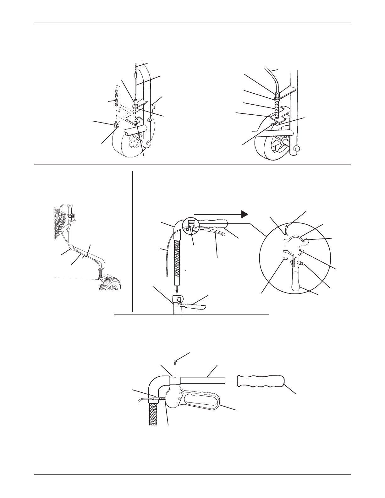
REMOVING/INSTALLING BRAKE WIRE - STEPS 1 AND 6
Cable Adjuster Unit
Spring
Brake
Wire
Clamp
Phillips Screw
Brake Cable
Brake
Wire
Brake
Cable
Adjuster
Unit
Locknut
Hole
ASSEMBLEDDISASSEMBLED
Cable Adjuster Unit
Cable Adjuster
Unit Locknut
Spring
Brake
Phillips Screw
Brake Cable
Brake
Wire
Clamp
REMOVING/INSTALLING
BRAKE CABLE
- STEPS 2 AND 5
Tie Wrap
Side
Frame
Brake
Cable
REMOVING/INSTALLING HAND BRAKE - STEPS 3 AND 4 (AFTER 3/8/00)
REMOVING/INSTALLING HAND BRAKE - STEPS 3 AND 4
(BEFORE 3/7/00) (BRAKE KITS ONLY)
Push
Handle
Brake
Cable
Side
Frame
BACK OF ROLLATOR
Lock
Button
Adjustment
Lever
Hand
Grip
Hand
Brake
Washer
Locknut
Hex Bolt
Mounting
Bracket
Hand
Brake
(BRAKE KITS ONLY)
Phillips Screw
Hook
Slot
Lock
Button
Mounting Hole
Hand Brake
Adjustment Nut
FIGURE 1 - REPLACING SPRINT CANES AND BRAKES
Push Handle
Hand Grip
Hand Brake
Hand Brake Nut
3
Page 4
REPLACING SPARTAN CANES AND
BRAKES
Preparing Spartan for Brake Replacement
(FIGURE 2)
1. Perform one (1) of the following:
INSTALLING BRAKE KIT (BEFORE 3/7/00) - Re-
move EXISTING hand brake.
A . Remove the hex bolt, washer and locknut secur-
ing the hand brake to the push handle.
B. Remove the hand brake.
INSTALLING BRAKE KIT (AFTER 3/8/00) - Re-
move EXISTING hand brake.
A. Remove EXISTING hand grip from the push
handle and discard.
B. Remove the phillips screw securing the EXIST-
ING hand brake to the push handle.
C. Pull the EXISTING hand brake off of the push
handle.
2. Perform one (1) of the following:
INST ALLING BRAKE KIT - Proceed to STEP 3.
INSTALLING CANE KIT - Remove the push handle.
Perform the following:
A. Rotate adjustment lever counterclockwise to
loosen. DO NOT remove.
B. Pull UP on the push handle to remove.
3. Remove the tire. Perform the following:
A . Remove the cap covers from both sides of the tire.
B. Remove the screw and locknut that secure the tire
to the rollator.
C. Remove the tire.
4. Replace the brake. Refer to
BRAKES in this procedure of the instruction sheet.
REPLACING SP ARTAN
REMOVING THE HAND BRAKE - STEP 1
(BEFORE 3/7/00) (BRAKE KITS ONLY)
Hex Bolt
(STEP 1A)
Push Handle
Washer
(STEP 1A)
Locknut
(STEP 1A)
Hand Brake
(STEP 1B)
REMOVING PUSH HANDLE - STEP 2
(CANE KITS ONLY)
Push
Handle
(STEP 2B)
Adjustment
Lever
(STEP 2A)
REMOVING THE HAND BRAKE - STEP 1
(AFTER 3/8/00) (BRAKE KITS ONLY)
Phillips
Screw
Hand Brake
Push Handle
Hand Grip
REMOVING THE TIRE - STEP 3
Cap Cover
Screw
(STEP 3B)
(STEP 3A)
Tire
(STEP 3C)
Locknut
Cap Cover
(STEP 3A)
(STEP 3B)
FIGURE 2 - REPLACING SPARTAN CANES AND BRAKES - PREPARING SPARTAN FOR BRAKE
REPLACEMENT
4
Page 5

Removing/Installing The Spartan Brake
Pad Only (FIGURE 3)
1. Remove the tire. Perform the following as shown in
DET AIL “A” of FIGURE 3:
A . Remove the cap covers from both sides of the tire.
B. Remove the screw and locknut that secure the tire
to the rollator.
C. Remove the tire.
2. Remove the phillips screw securing the brake pad to
the plunger assembly as shown in FIGURE 3.
3. Remove the brake pad from the rollator .
4. Align the mounting holes of the NEW brake pad and
plunger assembly , as shown in FIGURE 3.
5. Install the phillips screw. T ighten securely.
6. Reverse STEP 1 to reinstall the tire
Cap Cover
DETAIL “A”
Tire
Locknut
Screw
Cap Cover
Mounting
Hole
Plunger
Assembly
Brake Pad
Phillips Screw
FIGURE 3 - REMOVING/INSTALLING THE
SPARTAN BRAKE PAD
Replacing Spartan Brakes (FIGURE 4)
1. Remove the brake pad. Refer to REMOVING/INSTALLING THE SPARTAN BRAKE P ADS in this procedure of the instruction sheet.
2. Remove the plunger assembly. Perform the following:
A. Pry the plunger assembly out of the rollator leg
with a flat screwdriver .
3. Remove the EXISTING brake wire stop. Perform the
following:
A. Depress and hold the plunger (small end of the
plunger assembly).
B. With a flat screwdriver, pry the EXISTING brake
wire stop up over the lip of the insert.
C. Pull the EXISTING brake wire stop down to pull the
brake wire through the slot in the lip of the insert.
4. Disassemble the plunger assembly . Perform the following:
A . Remove the insert from the plunger.
B. Position the EXISTING brake wire stop into the open-
ing in the plunger slot.
C. Slide the spring off the plunger .
D. Remove the EXISTING brake wire from the plunger.
5. Pull the EXISTING brake wire and cable UP through the
rollator leg.
6. Thread the end of the NEW brake wire and cable DOWN
into the rollator leg.
7. Assemble the plunger assembly. Perform the following:
A. Insert the NEW brake wire stop into the slot opening
in the plunger.
B. Ensure NEW brake wire is positioned in the plunger
slot as shown in FIGURE 4.
C. Slide the spring onto the plunger .
D. Slide the small end of the insert onto the plunger .
8. Secure the NEW brake wire stop. Perform the following:
A . Align the slots on both the plunger and the insert.
B. Grasp and hold the wire stop.
C. Depress and hold the plunger .
D. Pull the wire stop up through the slot in the insert and
over the lip.
9. Insert the plunger end of the plunger assembly into the
rollator leg.
NOTE: A rubber mallet may be necessary to ensure the
plunger assembly is fully inserted into the rollator leg.
10. Reinstall the brake pad. Refer to REMOVING/INST ALLING THE SP ARTAN BRAKE P ADS in this procedure
of the instruction sheet.
1 1. Assemble the Spartan rollator for use. Refer to
BLING THE SP ARTAN FOR USE in this procedure of
the instruction sheet.
5
ASSEM-
Page 6

REMOVING/
INSTALLING THE
PLUNGER
ASSEMBLY
- STEPS 2 AND 9
Rear Frame
REMOVING/SECURING THE
BRAKE WIRE STOP
- STEPS 3 AND 8
Lip
Screwdriver
Insert
Brake Wire Stop
Plunger
Flat
Plunger
Flat
Slot Opening
Screwdriver
Plunger
Assembly
DISASSEMBLING/ASSEMBLING THE PLUNGER
ASSEMBLY - STEPS 4 AND 7
Brake
Brake
Spring
Wire
Slot
Wire
Slot
Opening
Stop
Insert
Slot
REMOVING/INSERTING
THE BRAKE CABLE
- STEPS 5-6
Brake
Cable
Rear Frame
FIGURE 4 - REPLACING SPARTAN CANES AND BRAKES - REPLACING SPARTAN BRAKES
Assembling Spartan For Use (FIGURE 5)
NOTE: The Spartan rollator should only be assembled
AFTER replacing spartan brakes. Refer to
ING SPARTAN BRAKES in this procedure of the instruction sheet.
1. Install tire. Perform the following:
A . Position the tire so the mounting holes are aligned
with the mounting holes in the rollator leg.
B. Install the screw from the inside of the rollator,
through both sets of mounting holes.
REPLAC-
C. Secure the tire to the rollator with the locknut.
Tighten securely .
D. Install the cap covers over the screw and locknut.
2. Perform one (1) of the following:
INST ALLING CANE KIT - Install the push handle. Per-
form the following:
A . Remove the hex bolt, washer and locknut securing
the hand brake to the push handle.
6
Page 7

B. Remove the hand brake.
C. Turn the adjustment lever COUNTERCLOCK-
WISE.
D. Insert push handles into side frames with the hand
grip facing the back of the rollator.
3. Perform one (1) of the following:
INSTALLING BRAKE KIT (BEFORE 3/7/00) -
Install NEW hand brake.
A . Position the handbrake assembly under the push
handle so the lock button is facing OUT, the tip of
the hand brake is towards the end of the hand grip
and the brake cable is AW AY from the hand grip.
B. Position the hook portion of the hand brake clamp
through the slot in the hand brake assembly .
C. Install the washer , hex bolt and locknut to secure
the hand brake assembly to the push handle.
D. Securely tighten the locknut.
INSTALLING BRAKE KIT (AFTER 3/8/00) - Install
NEW hand brake.
A . Push the NEW hand brake onto the push handle.
NOTE: If necessary, twist the hand brake while pushing to
install on the push handle.
B. Align the mounting holes of the NEW hand brake with
the mounting hole in the push handle.
C. Install the phillips screw through both mounting holes.
Securely tighten.
D. Apply a thin coat of hair spray on the inside of the
foam grip and on the push handle.
NOTE: This application will make it easier to slide
the grip onto the push handle.
E. Slide new grip onto one end of the push handle.
4. Adjust the push handle. Refer to
AND SPAR TAN PUSH HANDLES in this instruction sheet.
5. Adjust the hand brake. Refer to
AND SPARTAN HAND BRAKES in this instruction sheet.
ADJUSTING SPRINT
ADJUSTING SPRINT
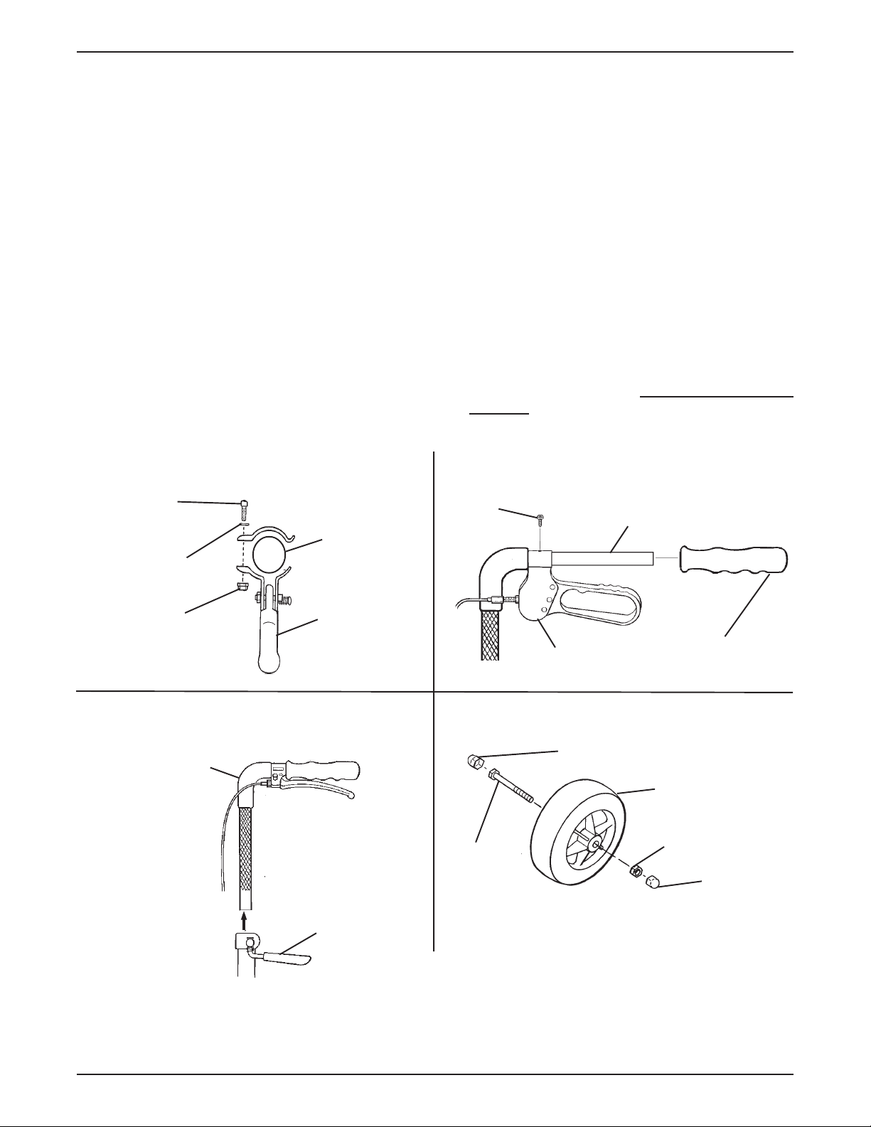
INSTALLING/REMOVING THE HAND
BRAKE (BEFORE 3/7/00) - STEPS 2 AND 3
Hex Bolt
2A AND 3C)
Washer
2A AND 3C)
Locknut
2A AND 3C)
Push Handle
(STEPS
(STEPS
(STEPS
Hand Brake Clamp
Hook
Slot
Lock Button
Hand Brake
2B AND 3A)
(STEP 3B)
(STEP 3B)
(STEP 3B)
(STEP
INSTALLING PUSH HANDLE
- STEPS 2 AND 3
Push Handle
(STEPS 2D
AND 3A)
Brake Cable
(STEP 3A)
Textured
T ubing
Adjustment Lever
(STEP 2A)
Hand Grip
(STEP 3A)
Tip of Hand
Brake
(STEP 3A)
INSTALLING/REMOVING THE HAND
BRAKE (AFTER 3/8/00) - STEPS 2 AND 3
Hand Brake
Adjustment
Nut
Hand Brake Nut
Phillips Screw
Mounting Hole
Hand Grip
Push Handle
Hand Brake
INSTALLING THE TIRE - STEP 1
Cap Cover
Screw
(STEP 3B)
(STEP 3A)
Tire
(STEP 3C)
Locknut
Cap Cover
(STEP 3A)
(STEP 3B)
FIGURE 5 - REPLACING SPARTAN CANES AND BRAKES - ASSEMBLING SPARTAN FOR USE
7
Page 8

ADJUSTING SPRINT AND SPARTAN
PUSH HANDLES (FIGURE 6)
NOTE: For the most comfortable position, make sure the
adjustment is performed while wearing the most frequently
worn shoes.
Cable
Cable Brake
Handle Locknut
Screw Mechanism
NOTE: COUNTERCLOCKWISE/CLOCKWISE directions are determined by standing behind the
rollator (users position).
1. Position the push handle so that when the user’s arm
is down to their side, the hand grip is at wrist height.
NOTE: This will ensure the arms are at an approximate
o
20
-30o bend when using the rollator.
2. Ensure that the push handle is adjusted ONL Y where
the tubing is textured (FIGURE 6).
3. Securely tighten push handle by turning adjustment
lever CLOCKWISE.
NOTE: When securely tightened, the push handle should
not move.
4. Before using the rollator, refer to USING HAND
BRAKES in the Sprint and Spartan instruction sheet,
Part Number 1076166.
ADJUSTING SPRINT AND
SPARTAN HAND BRAKES
Adjusting Cable Brake Handle (FIGURE 6)
(Before 3/7/00)
NOTE: Adjusting the cable brake handle will increase/decrease the cable brake handle tension.
NOTE: COUNTERCLOCKWISE/CLOCKWISE directions are determined by standing behind the
rollator (users position).
FIGURE 6 - ADJUSTING CABLE BRAKE HANDLE
Adjusting Cable Brake Handle (FIGURE 7)
(Before 3/8/00)
NOTE: Adjusting the cable brake handle will increase/decrease the cable brake handle tension.
NOTE: COUNTERCLOCKWISE/CLOCKWISE directions are determined by standing behind the
rollator (users position).
1. Loosen the brake handle adjustment nut by turning
CLOCKWISE.
2. Do one (1) of the following:
A. Loosen brake handle tension - turn brake
handle nut COUNTERCLOCKWISE.
B. Tighten brake handle tension - turn brake
handle nut CLOCKWISE.
3. Turn the brake handle adjustment nut CLOCKWISE to secure in place.
4. Do one (1) of the following:
A. Acceptable tension - repeat STEPS 1 - 3 for
opposite side, if necessary.
B. Unacceptable tension - refer to
CABLE ADJUSTER UNIT in this procedure of
the instruction sheet.
5. Refer to
BRAKES in this instruction sheet.
LOCKING/UNLOCKING/USING HAND
ADJUSTING
1. Turn the cable brake handle locknut counterclockwise
to loosen.
2. While holding the cable brake handle locknut with one
(1) hand, perform one (1) of the following:
A. To increase tension, turn the screw mechanism
COUNTERCLOCKWISE.
B. T o decrease tension, turn the screw mechanism
CLOCKWISE.
3. Securely tighten cable brake handle locknut by turning clockwise.
4. If the tension of the brake handle is STILL too loose/tight,
refer to
WHEEL ASSEMBLY - SPRINT ONL Y in this instruction
sheet.
ADJUSTING CABLE ADJUSTER UNIT -
Cable
Brake Handle
Adjustment Nut
Brake Handle Nut
FIGURE 7 - ADJUSTING CABLE BRAKE HANDLE
8
Page 9

Adjusting Cable Adjuster Unit - Wheel
Assembly - MODEL 65400 ONLY
(FIGURE 8)
Adjusting Cable Adjuster Unit - Wheel
Assembly - MODEL 65420 ONLY
(FIGURE 9)
NOTE: Adjusting the cable adjuster unit will increase/
decrease the cable brake pressure on the wheels.
NOTE: COUNTERCLOCKWISE/CLOCKWISE directions are determined by standing behind the
rollator (users position).
1. Loosen the cable brake adjuster unit locknut.
2. Do one (1) of the following:
A. To increase tension, turn the cable adjuster unit
COUNTERCLOCKWISE.
B. T o decrease tension, turn the cable adjuster unit
CLOCKWISE.
3. Retighten the cable adjuster unit locknut.
4. Test the brake. If the tension of the brake handle is
STILL too loose/tight, perform the following:
A . Repeat STEP 1.
B. Loosen the phillips screw on the brake clamp.
C. Pull the brake wire further through the brake clamp.
NOTE: There will be additional excess wire. It may be
necessary to fold wire up to keep wire from interfering
with brake action.
NOTE: Adjusting the cable adjuster unit will increase/
decrease the cable brake pressure on the wheels.
NOTE: COUNTERCLOCKWISE/CLOCKWISE directions are determined by standing behind the
rollator (users position).
1. Loosen the cable brake adjuster unit locknut.
2. Do one (1) of the following:
A. To increase tension, turn the cable adjuster unit
COUNTERCLOCKWISE.
B. T o decrease tension, turn the cable adjuster unit
CLOCKWISE.
3. Retighten the cable adjuster unit locknut.
4. Test the brake. If the tension of the brake handle is
STILL too loose/tight, repeat STEPS 1-3.
Brake Handle
Cable
Cable Adjuster Unit
Cable Adjuster
Unit Locknut
Cable Adjuster Unit
Cable Adjuster
Unit Locknut
Brake
Phillips Screw
Brake Cable
Brake
Clamp
FIGURE 8 - ADJUSTING CABLE ADJUSTER UNIT -
WHEEL ASSEMBLY - SPRINT ONLY
T op of Rear Leg
FIGURE 9 - ADJUSTING CABLE ADJUSTER UNIT -
WHEEL ASSEMBLY - MODEL 65420 ONLY
9
Page 10

REPLACING STINGRAY AND
STARGAZER BRAKES (FIGURE 10)
NOTE: COUNTERCLOCKWISE/CLOCKWISE directions are determined by standing beside the rollator.
1. Remove the EXISTING brake wire. Perform the following:
A. Loosen the hex screw securing the EXISTING
brake wire to the brake.
B. Loosen the caster housing nut.
C. Pull EXISTING brake cable up to pull brake wire
through the hole in the brake and through the caster
housing nut and caster housing adjustment nut.
NOTE: It may be necessary to straighten the end of the
brake wire to pull it through the brake.
2. Pull EXISTING brake cable UP through the guide on
the rollator frame to remove.
3. Perform one (1) of the following:
INST ALLING CANE KIT - Remove EXISTING push
handle. Perform the following:
A . Remove adjustment knobs and screws from both
sides of the frame by turning COUNTERCLOCKWISE.
B. Pull UP on the EXISTING push handle to remove
from frame.
INST ALLING BRAKE KIT - Remove EXISTING hand
brake. Perform the following:
A. Remove the phillips screw securing the EXIST-
ING hand brake to the push handle.
B. Pull the back support out of the push handle.
C. Pull the EXISTING hand brake off of the push
handle.
NOTE: If necessary , twist the hand brake while pulling
to remove it from the push handle.
4. Perform one (1) of the following:
INST ALLING CANE KIT - Install NEW push handle. Per-
form the following:
A . Insert NEW push handles into frames.
B. Align the mounting holes of the NEW push handle
with the mounting holes in the frame.
C. Install the screw from the inside of the frame through
both sets of mounting holes.
D. Install the adjustment knob on the outside of the frame
by turning CLOCKWISE.
INSTALLING BRAKE KIT - Install NEW hand brake.
Perform the following:
A . Push the NEW hand brake onto the push handle.
NOTE: If necessary, twist the hand brake while pushing to
install on the push handle.
B. Push the back support into the push handle.
C. Align the mounting holes of the NEW hand brake with
the mounting hole in the push handle.
D. Install the phillips screw through both mounting holes.
Tighten until snug.
5. Thread NEW brake cable DOWN through the guide on
the rollator frame.
6. Install NEW brake wire. Perform the following:
A . If necessary, loosen the caster housing nut.
B. Thread NEW brake wire through caster housing ad-
justment nut , caster housing nut and hole in brake.
C. Tighten hex screw to secure NEW brake wire to brake.
NOTE: If necessary , bend the excess brake wire UP to keep
it from interfering with brake action.
7. Adjust the push handle. Refer to ADJUSTING STINGRAY
AND STARGAZER PUSH HANDLE in this instruction
sheet.
8. Adjust the hand brakes. Refer to
GRAY AND ST ARGAZER HAND BRAKES in this instruction sheet.
ADJUSTING STIN-
ADJUSTING STINGRAY AND
STARGAZER PUSH HANDLE
(FIGURE 10)
NOTE: COUNTERCLOCKWISE/CLOCKWISE directions are determined by standing beside the rollator.
NOTE: For the most comfortable position, make sure the
adjustment is performed while wearing the most frequently
worn shoes.
1. Position the push handle so that when the user’s arm
is down to their side, the hand grip is at wrist height.
NOTE: This will ensure the arms are at an approximate
o
20
- 30o bend when using the rollator.
2. Do one (1) of the following:
A. STINGRAY (MODEL 65500) - install screw
into one (1) of the six (6) adjustment holes.
B. STARGAZER (MODEL 65600) - install screw
into one (1) of the four (4) adjustment holes.
3. Securely tighten with adjustment knob by turning
CLOCKWISE.
4. Repeat STEPS 1 - 3 for the other side.
NOTE: When securely tightened, the push handles should
not move.
10
Page 11

ADJUSTING STINGRAY AND
STARGAZER HAND BRAKES
(FIGURE 10)
Adjusting Hand Brake
NOTE: COUNTERCLOCKWISE/CLOCKWISE directions are determined by standing behind the rollator (users position).
1. Loosen the hand brake adjustment nut by turning
CLOCKWISE.
2. Perform one (1) of the following:
A. Loosen hand brake tension - turn hand brake
nut COUNTERCLOCKWISE.
B. Tighten hand brake tension - turn hand brake
nut CLOCKWISE.
3. Turn the hand brake adjustment nut CLOCKWISE to
secure in place.
REPLACING BRAKE WIRE/
ADJUSTING CASTER HOUSING
4. Perform one (1) of the following:
A. Acceptable tension - repeat STEPS 1 - 3 for op-
posite side, if necessary .
B. Unacceptable tension - refer to ADJUSTING
CASTER HOUSING in this procedure of the instruction sheet.
5. Refer to
BRAKES in the Stingray/Stargazer instruction sheet
Part Number 1076167.
LOCKING/UNLOCKING/USING HAND
Adjusting Caster Housing
1. Turn the caster housing nut on the bottom COUNTERCLOCKWISE to loosen.
2. Turn the caster housing adjustment nut COUNTERCLOCKWISE to loosen.
3. Retighten caster housing adjustment nut and caster
housing nut by turning CLOCKWISE.
4. Repeat STEPS 1 - 3 until tension is acceptable.
REPLACING BRAKE CABLE
Guide
Brake Cable
Caster Housing
Adjustment Nut
Brake
Brake Wire
Caster Housing
Nut
Hex Screw
REPLACING/ADJUSTING PUSH HANDLE
INSIDE
Push
Handle
Adjustment
Knob
Screw
Frame
Frame
Brake
Cable
REPLACING/ADJUSTING HAND BRAKE
Push
Handle
Hand
Brake
Push
Handle
Hand
Brake
Phillips Screw
Hand
Brake Nut
Mounting
Hole
Back Support
Hand Brake
Adjustment
Nut
Back Support
OUTSIDE
FIGURE 10 - REPLACING/ADJUSTING STINGRAY AND STARGAZER BRAKES/
ADJUSTING STINGRAY AND STARGAZER PUSH HANDLE
11
Page 12

Removing/Installing The Stingray Brake
Pad (FIGURE 11)
Cap
Cover
Tire
1. Remove the tire. Perform the following as shown in
DET AIL “A” of FIGURE 11:
A . Remove the cap covers from both sides of the tire.
B. Remove the screw and locknut that secure the tire
to the rollator forks.
C. Remove the tire.
2. Loosen the set screw securing the brake cable to the
EXISTING brake pad assembly .
3. Remove the mounting screw and locknut that secures
the EXISTING brake pad assembly to the rollator. Set
mounting screw aside.
NOTE: It may be necessary to straighten the end of the
brake wire to pull it through the brake pad assembly .
NOTE: Note the position and orientation of the EXISTING brake pad assembly prior to removing.
4. Pull the EXISTING brake pad assembly away from
the rollator forks and discard.
5. Position the NEW brake pad assembly between the
rollator forks and secure with the EXISTING mounting
screw and locknut as shown in FIGURE 1 1. Securely
tighten.
Screw
DETAIL “A”
Rollator
Forks
Mounting Screw
Locknut
Cap
Cover
Brake Cable
Locknut
NOTE: The new set screw is shipped installed as part of
the new brake pad assembly .
6. Insert brake wire through the new brake pad assembly and securely tighten the set screw.
7. Reverse STEP 1 to reinstall the tire.
8. T est brake, if necessary adjust brake.
9. If necessary , repeat STEPS 1-9 on remaining brake.
Invacare Corporation www.invacare.com
Set Screw
Brake Pad Assembly
FIGURE 11 - REMOVING/INSTALLING THE
STINGRAY BRAKE PAD
USA Canada
One Invacare Way 5970 Chedworth Way Invacare® and "Yes, you can" are trademarks of Invacare
Elyria, Ohio USA Mississauga, Ontario Corporation.
44036-2125 L5R 3T9, Canada © 2001 Invacare Corporation
800-333-6900 905-890-8838 Form No. 98-146 Part No. 1076198 Rev C (1) 1/01
 Loading...