

Spec
®
Spectra Plus
User Manual
Yes, you can.

CONTENTS
Forward - Advisory Safety Notice . . . . . . . . . . . . . . . . . . . . . . . . . . . . . . . . . . . . . . . . . . . . . . . . . . 1
Getting Acquainted With The Powerchair . . . . . . . . . . . . . . . . . . . . . . . . . . . . . . . . . . . . . . . . . . . . 2
Features - Joystick Control Knob Option . . . . . . . . . . . . . . . . . . . . . . . . . . . . . . . . . . . . . . . . . . . . .3
Seat and Backrest Adjustment . . . . . . . . . . . . . . . . . . . . . . . . . . . . . . . . . . . . . . . . . . . . . . . . . . . . . 4
Armrest Adjustment . . . . . . . . . . . . . . . . . . . . . . . . . . . . . . . . . . . . . . . . . . . . . . . . . . . . . . . . . . . . 5
Tension Adjustable Backrest . . . . . . . . . . . . . . . . . . . . . . . . . . . . . . . . . . . . . . . . . . . . . . . . . . . . . . 6
Manual Tilt-in-Space . . . . . . . . . . . . . . . . . . . . . . . . . . . . . . . . . . . . . . . . . . . . . . . . . . . . . . . . . . . .6
Controllers - PILOT Integral . . . . . . . . . . . . . . . . . . . . . . . . . . . . . . . . . . . . . . . . . . . . . . . . . . . . . .7
Controllers - Dynamic DL . . . . . . . . . . . . . . . . . . . . . . . . . . . . . . . . . . . . . . . . . . . . . . . . . . . . . . . .8
DX-REMG80I Master Remote . . . . . . . . . . . . . . . . . . . . . . . . . . . . . . . . . . . . . . . . . . . . . . . . . . 9-11
Controllers - PILOT+ . . . . . . . . . . . . . . . . . . . . . . . . . . . . . . . . . . . . . . . . . . . . . . . . . . . . . . . . 12-16
Controllers - Options - Chin/Dual Attendant . . . . . . . . . . . . . . . . . . . . . . . . . . . . . . . . . . . . . . . . . 17
Transfers - Getting in and out of the Chair . . . . . . . . . . . . . . . . . . . . . . . . . . . . . . . . . . . . . . . . . . .18
Footrests - Elevating Legrests . . . . . . . . . . . . . . . . . . . . . . . . . . . . . . . . . . . . . . . . . . . . . . . . . . . . 19
Freewheel Mode - Motor Dis-engage . . . . . . . . . . . . . . . . . . . . . . . . . . . . . . . . . . . . . . . . . . . . . . . 20
Kerb Climbing . . . . . . . . . . . . . . . . . . . . . . . . . . . . . . . . . . . . . . . . . . . . . . . . . . . . . . . . . . . . . . . . 21
Disassembly - For Transportation . . . . . . . . . . . . . . . . . . . . . . . . . . . . . . . . . . . . . . . . . . . . . . . . . 22
Detachable Motors . . . . . . . . . . . . . . . . . . . . . . . . . . . . . . . . . . . . . . . . . . . . . . . . . . . . . . . . . . . . 23
Drive Wheel Removal . . . . . . . . . . . . . . . . . . . . . . . . . . . . . . . . . . . . . . . . . . . . . . . . . . . . . . . . . . 24
Manual Brakes - Drive Wheel-Locks . . . . . . . . . . . . . . . . . . . . . . . . . . . . . . . . . . . . . . . . . . . . . . . 24
Transportation - Restraint Methods . . . . . . . . . . . . . . . . . . . . . . . . . . . . . . . . . . . . . . . . . . . . . . . . 25
Tray - Fitting & Operation . . . . . . . . . . . . . . . . . . . . . . . . . . . . . . . . . . . . . . . . . . . . . . . . . . . . . . . 27
Lateral Supports - Fitting & Operation . . . . . . . . . . . . . . . . . . . . . . . . . . . . . . . . . . . . . . . . . . . . .28
Charging the Batteries . . . . . . . . . . . . . . . . . . . . . . . . . . . . . . . . . . . . . . . . . . . . . . . . . . . . . . . . . . 29
Battery Connections . . . . . . . . . . . . . . . . . . . . . . . . . . . . . . . . . . . . . . . . . . . . . . . . . . . . . . . . . . . 30
Maintenance & Care . . . . . . . . . . . . . . . . . . . . . . . . . . . . . . . . . . . . . . . . . . . . . . . . . . . . . . . . . . . 31
Fault Finding . . . . . . . . . . . . . . . . . . . . . . . . . . . . . . . . . . . . . . . . . . . . . . . . . . . . . . . . . . . . . . . . . .32
Technical Information . . . . . . . . . . . . . . . . . . . . . . . . . . . . . . . . . . . . . . . . . . . . . . . . . . . . . . . . . . 33
Approved Accessories . . . . . . . . . . . . . . . . . . . . . . . . . . . . . . . . . . . . . . . . . . . . . . . . . . . . . . . . . . 34
Product Description
The power chair supplied as standard, features rear wheel drive, Gel batteries, standard height backrest,
detachable, width and height adjustable armrests, detachable, adjustable height footrests and a joystick controller
mounted for either right or left hand control.
Without the use of tools the drive motor units are detachable and together with detachable battery box units and
disassembled frame, allow the power chair to be stowed for transportation in a suitable vehicle.
It may be used to transport a user in a moving vehicle provided the separate recommended guidelines are followed.
The product should be serviced as recommended by an authorised INVACARE dealer to ensure continual, safe
and reliable operation.
For details and additional special options for users with greater dependency, refer to your Healthcare
Professional/Prescriber or authorised INVACARE dealer.
!
FOREWORD
Important safety operating and maintenance instructions are contained in this user
manual. We urge you to read and understand it before operating your power chair and
refer to it as often as needed to help maintain safe use and all-round performance.
All procedures involved should be practiced until you are familiar with them. However, if used
improperly, it is possible for the wheelchair to become unstable. You should learn the individual
characteristics and capabilities, as well as limitations, of your own powered wheelchair.
Basic safety procedures in this user manual are to be used as a guide only. You may find it necessary to
develop your own methods for safely solving encountered problems. Never hesitate to ask for assistance.
Your powered wheelchair should receive maintenance on a regular schedule. It is recommended that the
periods between services should be 12 months. The maximum period between safety checks for the
manual wheel - lock adjustment and the electronic brake function should be 6 months.
PURPOSE OF THE POWER CHAIR
Standard power chairs are suitable for persons who require independent mobility combined with comfort,
manoeuvrability, reliability and minimal maintenance.
The intended user should possess some degree of ability with at least one hand and arm, reasonable
eyesight and a degree of spatial awareness and have received training in the use of the product,
preferably in their normal environment. Their maximum weight can be found at the rear of this manual.
It is suitable for use indoors and outdoors on dry, reasonably smooth level surfaces. It climbs slopes up to
20% (1 in 5) and kerbs up to 10cm high (an optional device may be required). It should not be used in heavy
rain or snow, loose slippery surfaces and slopes, on wet grass, etc. Passengers must NOT be carried.
Excess baggage outside of the seating area can affect stability.
ADVISORY SAFETY NOTICE
Power chairs are designed to operate in appropriate environments.
However, radio wave sources such as radio and TV broadcasting stations,
amateur radio transmitters and portable telephones can affect powered
wheelchairs.
Portable communication equipment such as citizen band radios and
portable telephones should be switched OFF whilst operating the
wheelchair.
If unintentional movement or brake release occurs, turn the wheelchair
OFF as soon as it is safe to do so.
Unauthorised modifications or the use of non-Invacare approved replacement parts may change the
structure of the wheelchair and could create a hazardous condition. Invacare will not be liable for any
unauthorised changes and modifications from the specifications of the power chair supplied.
All information and specifications in this manual are current at the time of printing, However, because of
Invacare’s policy of continual product improvement, we reserve the right to make changes at any time
without notice.
1

!
GETTING ACQUAINTED WITH YOUR NEW POWER CHAIR
Please ensure your dealer returns the WARRANTY REGISTRATION CARD. This will ensure your vehicle
is covered for the relevant warranty periods against failures due to defects in manufacturing or materials.
Please see the Owner’s Warranty Card supplied for full details.
RECOMMENDED ADJUSTMENTS TO BE CARRIED OUT BY A TRAINED AUTHORISED
INVACARE DEALER ARE IDENTIFIED WITH THIS SYMBOL.
SAFETY PRECAUTIONS
Before using your power chair, read and understand the following safety precautions:-*
• Keep your powered wheelchair in good working order. As with all electro-mechanical
vehicles, it will benefit from regular service inspections at the recommended intervals.
• We recommend that at 6 monthly intervals to check electronic brake function, manual
wheel - lock adjustment and the motor disengage operation.
• Always remember to use a safety belt when operating the wheelchair outdoors.
• Your powerchair is capable of negotiating slopes of up to 11 degrees (1 in 5 gradient), however, the
recommended safe slope for the wheelchair is advised as 6 degrees (1 in 10 gradient). Also, see page
8 - recommended driving position, and section 3 - Negotiating Slopes / Gradients..
• Take special care in bad weather. Braking and tyre grip may be affected on
wet or icy surfaces, take care on slopes and uneven surfaces.
Do not attempt to drive across slopes, which may make the vehicle
unstable, increasing the possibility of an accident and possible personal
injury.
• When climbing hills or slopes it is important to travel up in one motion.
Starting a forward movement from stationary on a slope requires extra care
to avoid tipping backwards. Start slowly and accelerate cautiously.
• When travelling down an incline, select a low speed, stop periodically if the
wheelchair moves faster than anticipated. Push the joystick forward slowly
to continue the descent. Do not lean forward.
• Avoid parking on the edge of rivers, ponds, lakes, sea, etc.
• Adjustments should only be carried out by your authorised INVACARE®
dealer to ensure correct operation and safe use.
Representative models of Invacare powered wheelchairs are tested for use in
a moving motor vehicle using recommended restraint systems. For further
information contact your authorised
INVACARE dealer. It is the responsibility of the person or authority transporting the wheelchair with an
occupant seated, to ensure the safety of the occupant and other passengers.
2
FEATURES
3
Motor speed and direction are regulated by the joystick control unit. With practice, automatic control of
acceleration, braking and change of direction will ensure a smooth, jerk-free ride. The variable speed
selector gives you total control in any environment.
The power chair cannot be driven when the batteries are being charged. Controller circuits are designed
to prevent operation during the charging process.
CHARGING • The battery gauge will indicate that your batteries are low.
BATTERIES • The batteries fitted as standard are completely sealed and therefore cannot be
Charging is straightforward, (Refer to enclosed booklet).
spilled like conventional ‘wet’ cells. Total performance and reliable operation is
dependent on the care and understanding of batteries and battery charging.
Please refer to the appropriate section and separate booklet supplied. Sealed Gel
batteries are classed as non hazardous by all air transport and travel authorities.
Mobility vehicles fitted with these batteries can be safely taken onto aeroplanes,
ships, buses, ambulances or trains without having to remove the batteries from
the equipment.
TYRES • Pneumatic drive wheels and castors are fitted as standard. Puncture proof wheels
will alleviate the need to maintain pressures and give a smooth but slightly harder
ride. These are available as options.
UPHOLSTERY * The upholstery complies with the requirements for resistance to cigarette and
match ignition ISO7176:16. Refer to section on cleaning and care of upholstery
materials. Prolonged exposure to ultra-violet light will reduce the life of the
upholstery, protect against sunlight.
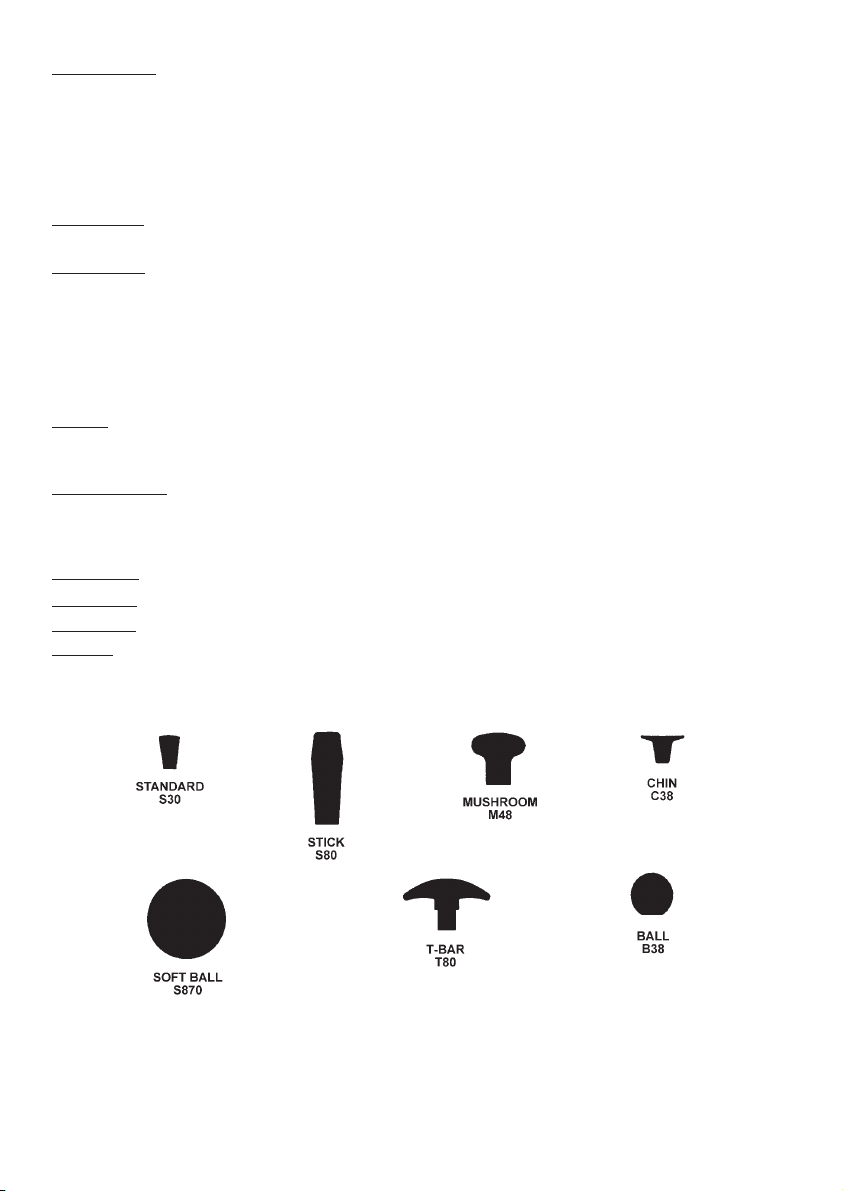
OPTIONAL * The knob fitted to your joystick is supplied as standard and is suitable for most
JOYSTICK
applications. If you find this unsuitable for your operation there is a range of
alternatives available. Please contact your wheelchair distributor for advice. Do
CONTROL not replace the joystick knob with any unauthorised device - it may cause
KNOBS
hazardous operation.
SEAT AND BACKREST ADJUSTMENT
4
C
Warning: It should be noted that under certain conditions, and configurations of the
wheelchair, ie. for users with limited / no lateral body control, and with the backrest in the
reclined position, there is the potential to create a body trap between the armrest / side-
!
Before sitting in the chair, make sure it is NOT switched ON. If it is ON, the battery condition indicator (10
Bar display) will be illuminated.
SEA
T DEPTH ADJUSTMENT - 35mm depth adjustment
The individual fitting of the seating allows the seat depth to be adjusted by 35mm (1“). The adjustment,
which is usually only done once, is carried out as follows. You will need a large cross-headed screwdriver
and a 13mm spanner.
1. Prise off plastic cap at point A, unscrew and remove the screw and nut, repeat each side.
2. Move the backrest mounting bracket backwards to the extended position. Replace the nut and screw
into the selected hole and firmly fasten, replace plastic cap, repeat each side.
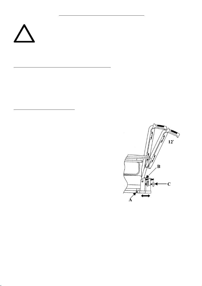
BACKREST ANGLE ADJUSTMENT
The backrest angle can be adjusted from 90˚rearwards through 12˚ The adjustment, which is normally
only required to be done once, is carried out in the
following sequence (see diagram) with the aid of the
13mm spanner and the cross-headed screwdriver. Do
the same adjustment for both sides.
1. Release the lock nut B located on the cross-headed
screw.
2. Screw the locking hand-wheel C partially out.
3. Screw the cross-headed screw in or out to give the
desired position. Adjust position of hand-wheel as
necessary.
4. Position the lock nut B up to the mounting bracket
and fully tighten.
5. Re-tighten the hand-wheel C fully; ensure backrest
assembly is secure.
panel and the backrest.
Suitable accessories are available from Invacare (lateral trunk supports_ to eliminate this risk.
Please note: Each backrest tube must be positioned in the same plane or the backrest will be twisted.
The backrest can be either folded down or detached from the chair base.
Follow these additional instructions: -
1. Unscrew the hand-wheel C approximately five full turns. Lift the backrest upwards and then fold
forwards onto the seat. Adjust armrest width to accommodate if required.
2. To detach, unscrew the hand-wheel an additional three to four turns. Do not loosen the cross-headed screw.
3. Push the backrest slightly forward and lift upwards.
4. To re-locate the backrest assembly, ensure the pins are correctly aligned into the slots of the mounting
bracket, fully re-tighten the hand-wheel on both sides.
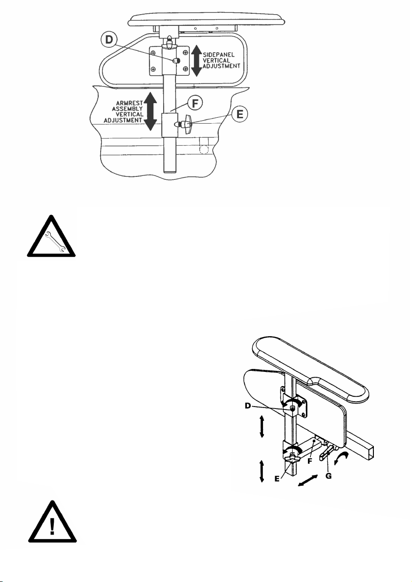
Armrest Adjustment
The armrest can be pre-set for height by positioning the self-tapping screw (F) in one of
the holes in the armrest tube. To adjust the height of each armrest, first release the locking
lever (E) which clamps the arm tube, while holding onto the armrest. Move the armrest to
the desired height position, re-tighten the locking wing screw (E). The locking lever (if
fitted) can be re-positioned without losing the clamping pressure, pull the lever slightly
outwards and turn to a more suitable locating angle.
The padded side panel can also be set to a desired height. Loosen the slotted screw (D) located in the
fixing bracket, re-tighten when desired position is achieved.
Width Adjustment
The transverse width adjustment is achieved by releasing
locking lever (G) and positioning the armrest tube to width
required and re-tightening locking lever (G). To remove the
transverse width adjustment armrest assembly complete
to allow removal of the front battery box/controller
assembly: remove seat, release locking lever (G), depress
spring button lock (F) and withdraw complete armrest unit
sideways.
NOTE: When re-assembling to chair always ensure the
spring button lock (F) is on the inside of the horizontal
mounting tube of the sideframe to prevent accidental
dismantling of armrest unit.
CAUTION: The armrests are not intended for carrying the wheelchair.
5
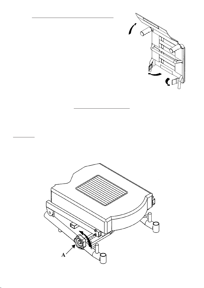
MANUAL TILT-IN-SPACE
To operate the manual tilt-in-space to allow the complete seat/backrest to tilt backwards, turn the large
hand-wheel A until the desired sitting position is achieved. Rotating the hand-wheel in the opposite
direction will lower the seat/backrest section.
T
AKE CARE: WHEN DRIVING THE POWER CHAIR WITH THE TILT-IN-SPACE OUTDOORS, THE
SEAT TILT MUST BE RETURNED TO THE NORMAL LOWERED POSITION BEFORE ATTEMPTING
KERB CLIMBING OR ASCENDING AND DESCENDING SLOPES. THIS ALSO APPLIES TO THE
OPTIONAL POWERED TILT-IN-SPACE OR POWERED RECLINING BACKREST.
TENSION ADJUSTABLE BACKREST
The backrest upholstery tension can be adjusted to achieve the
desired comfort for individual user requirements.
To achieve this, lift the backrest upholstery cover by peeling the
Velcro fastening and fold clear. Adjust the individual tension
straps to the occupant’s comfort.
Ensure the straps are correctly positioned and replace the
backrest cover, attaching securely by the Velcro fastening.
MANUAL TILT-IN-SPACE
To operate the manual tilt-in-space to allow the complete seat/backrest to tilt backwards, turn the large
hand-wheel A until the desired sitting position is achieved. Rotating the hand-wheel in the opposite
direction will lower the seat/backrest section.
T
AKE CARE: WHEN DRIVING THE POWER CHAIR WITH THE TILT-IN-SPACE OUTDOORS, THE
SEAT TILT MUST BE RETURNED TO THE NORMAL LOWERED POSITION BEFORE ATTEMPTING
KERB CLIMBING OR ASCENDING AND DESCENDING SLOPES. THIS ALSO APPLIES TO THE
OPTIONAL POWERED TILT-IN-SPACE OR POWERED RECLINING BACKREST.
6
Fault Type
The number of flashing
bars indicate the
possible area of fault.
Description
High battery voltage
Solenoid brake fault
Possible controller fault
Possible joystick fault
Charger Connected
Right motor wiring fault
Right motor disconnected
Left motor wiring fault
Left motor disconnected
Low battery voltage
G
R
E
E
N
Y
E
L
L
O
W
R
E
D
Speed
Control
Battery Gauge
On/Off Indicator
Status Readout
Joystick
On/Off Push
Button
Motor/Battery
Connector
HANDLING AND OPERATION - CONTROLLERS
Your wheelchair is fitted with a programmable electronic controller that is very simple to operate. There
are a selection of options, PILOT INTEGRAL, PILOT+ and the DYNAMIC DL. Whichever is selected will
be most appropriate for your individual needs. The appearance varies, the function and driving
characteristics are basically similar. The PILOT INTEGRAL is fitted as standard.
The following instructions cover all types and available controller options.
PILOT INTEGRAL
Before you sit in the chair, make sure it is not switched ON. If it is switched ON the battery gauge indicator
will be illuminated. Once you are sitting comfortably, press the on/off switch. The joystick controls the
speed and direction of the wheelchair. The further you push the joystick from the centre position the faster
the wheelchair will move. When you release the joystick the brakes are applied automatically. DO NOT use
the on/off switch to stop the chair unless there is an emergency. If the emergency stop is applied, the
chair will slow down and stop very quickly. This is called ‘SOFT STOP’. If the controller detects a
malfunction, either in its circuits, or in the wheelchair’s electrical system, it may
halt the chair depending on the severity of the problem.
The 10 segment battery gauge display will indicate the fault type by rapidly flashing the number of bars to
indicate the possible area of the fault. See the Fault Diagnostics section relevant to the type of controller.
The speed control sets the maximum speed of the wheelchair, turn clockwise to increase, anti-clockwise
to decrease.
You may charge the batteries through the charge socket at the front of the control unit. Refer to section
on batteries and battery charging. This socket may also be used for re-programming the controller should
this be necessary (consult your dealer).
The controller units are sophisticated electronic components, and must be handled with care. Always
clean your controller by wiping with a damp cloth only if it becomes contaminated with food or drink. Make
sure the controller is securely fixed to your wheelchair.
TruCharge Battery Gauge
This is a 10 segment illuminated display which indicates if the controller is turned on and also gives the
status of the battery, the controller and the wheelchair electrical system.
Red, yellow and green bars lit: Battery charged; controller and electrical system OK.
Red and yellow bars lit: Charge battery if possible; controller and electrical system OK.
Red bars only lit or slow flash: Charge battery as soon as possible, controller and electrical system OK.
Rapid flash of bars: Indicates a fault in the controller or electrical system. See below for fault diagnostics.
Ripple up and down of bars: Joystick displaced at turn on.
7
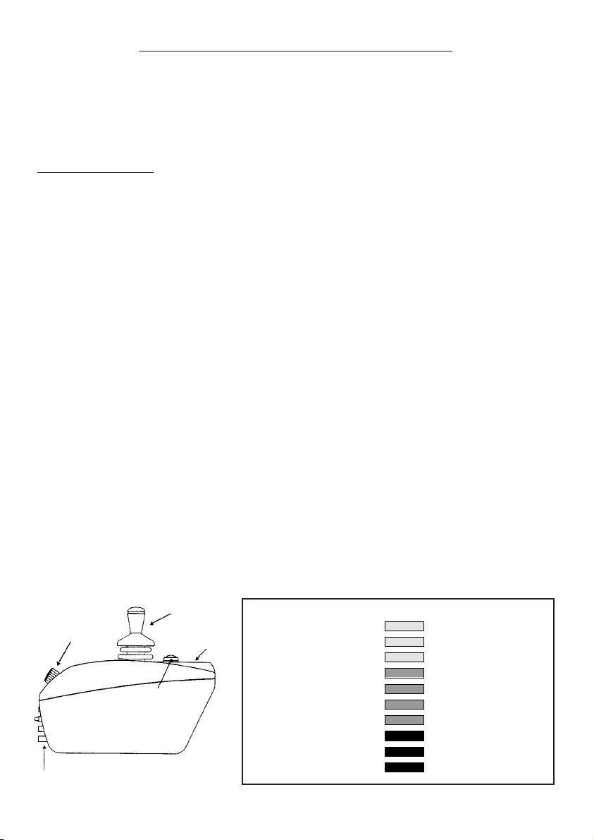
DYNAMIC DL CONTROLLER
When the ON/OFF button is pressed, a bleep tone can
be heard from the controller and the battery charge
indicator will light up confirming that power is switched on
and the wheelchair is ready to move.
The Speed Control Knob on the rear of the Controller
enables you to reduce the maximum speed at which the
wheelchair can travel when the joystick is fully deflected
in any direction. The more you turn this knob
anticlockwise, the lower will be the maximum speed, no
matter how far you push or pull the joystick.
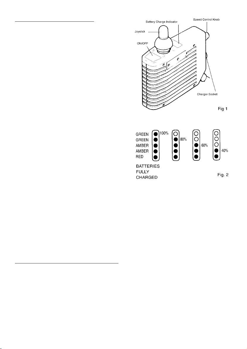
The Battery Charge Indicator (Fig. 2) lights up when the
ON/OFF button is pressed into ON. It gives you updated
information as to how much charge approximately is left
in the batteries, so that you can estimate how much
further you can drive before you have to recharge the
batteries. The reading will drop while the wheelchair is
being driven, and increase after the wheelchair has been
at a standstill for a few seconds. This is quite normal, and
it is best to check the indicator while the wheelchair is
stationary.
The battery charge indicator also informs you of any fault
condition when one or several of its lamps begin to flash.
Display flashing slowly: the wheelchairs moves slowly,
but with sluggish response and reduced speed indicates
the batteries are discharged below the critical level or possible controller or motor fault.
Display flashing rapidly: (twice per second) and the wheelchair not moving also indicates the batteries
are discharged below the critical level or a possible controller fault.
In both cases it is advisable to check and re-charge the batteries, if the fault indication persists, contact
the authorised INVACARE dealer.
On the rear face of the controller you find the Battery Charging Socket. Underneath is a special socket for
the connection of Programming Instruments if and when the response characteristics of the wheelchair
(acceleration, deceleration, damping etc.) are to be further adjusted to your needs (Consult your
authorised INVACARE dealer).
8
RECOMMENDED DRIVING POSITION
• INVACARE recommends that when driving your Spectra Plus during normal operating conditions the
following seat and back angles are maintained:
• Seat Angle: - approximately 4°
• Back Angle: - approximately 7°
• Failure to observe the above precautions whilst driving may lead to instability, damage to the chair, user
or those around you.
DX-REMG80I MASTER REMOTE
Please read these instructions carefully before using the DX-REMG80I, and keep this leaflet safe for future
reference.
For Information: My Local wheelchair services representative is: ......................................................................
Based at ............................................ Telephone no:................................ Department: ..................................
1) IMPORTANT INFORMATION FOR YOUR SAFETY
The information in this manual is a supplement to the user manual issued by Invacare. Do not operate this
equipment without reading, understanding and following the proper instructions and manuals, otherwise injury
or damage may result.
2) INTRODUCTION
The DX-REMG80I Remote is a primary DX Remote containing a battery gauge, magnetic key and a horn. Up
to five individual Drive Programs or profiles are available. The DX-REMG80I also features two jack sockets
allowing the connection of two external switches to duplicate the functions of the On/Off and Drive Program
select buttons.
3) HANDLING AND TRANSPORTATION
To avoid any unnecessary damage to your control system whilst driving, avoid hitting obstacles with the
controller or joystick. This also applies when transporting your chair. Avoid dropping the control system & be
wary of possible damage to cables. (i.e. Being Trapped).
DX-REMG80I Remote fitting, testing and programming must be carried out by professionals
of the health care field or persons fully conversant with this process and the driver’s
capabilities. The control system should be demonstrated to the user when the chair is
supplied. Incorrect settings could cause injury to the driver or bystanders, or damage to the
wheelchair or surrounding property.
4) DRIVING THE WHEELCHAIR
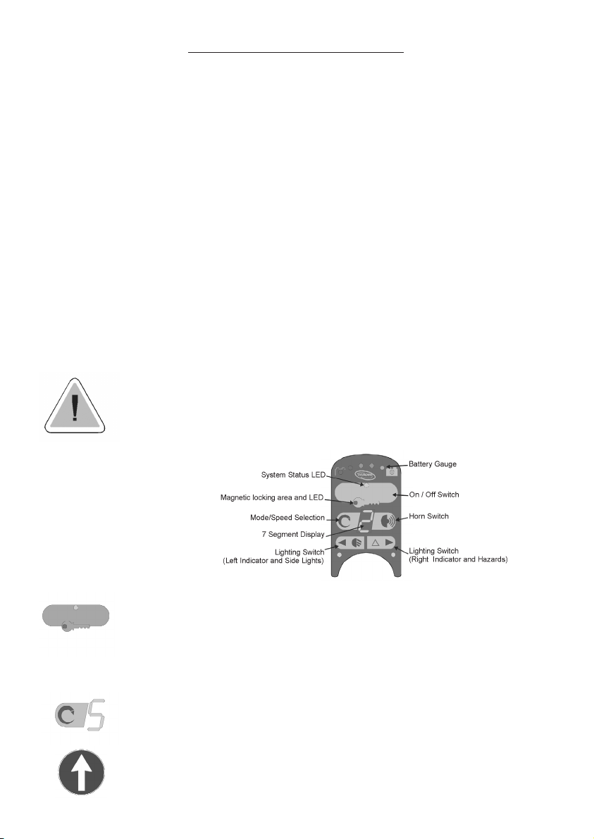
The G80I Keypad
Once you are seated in your wheelchair. Switch on DX-REMG80I by gently pressing and
releasing the on/off switch located on top of the controller at the front. The system status
light will light up to show power on. (If the status light flashes rapidly it indicates that the
joystick knob was not in its central position when the controller was switched on. Simply
allow the knob to return to the central position. If this condition persists for more than 5
seconds a latched fault will occur and the 7-segment display will begin to flash. If this
happens simply turn the remote on and off to clear the fault.
Drive Programs are selected using the Drive program selection switch. The selected drive
program or profile is displayed in the 7-Segment display. Drive programs or profiles may be
setup to change speed and/or select remote joysticks actuators, or lights. Appendix A
explains the operation of lighting and actuator functions.
Move the joystick a little in the direction you wish to travel. The further you move the joystick
knob, from the central rest position, the faster the chair will move. Small gentle movements
of the joystick give fine control.
9

Releasing the joystick and allowing it to return to the center position will bring the chair to a
controlled stop. When you have finished driving, switch off by pressing and releasing the on/off
switch.
The fuel gauge on the top surface of the DX-REMG80I will have all 6 lights on, if your batteries
are fully charged. As you use up the power by driving, the green lights and then the amber lights
will go out. When only the red lights are left on, it is time to re-charge your batteries. The red
light will flash as a further reminder.
A socket is provided at the front of the G80I to allow a battery charger to be connected. Follow the instructions for
charging your batteries in the wheelchair manual. CAUTION – Only use the charger supplied by the wheelchair
manufacturer. If in doubt contact your Wheelchair Services representative.
5) MAINTENANCE
1. The DX System should be regularly checked for integrity. Loose, damaged or corroded connectors or terminals,
or damaged cabling should be replaced.
2. All switchable functions on the DX System should be regularly tested to ensure they function correctly.
3. All DX system components should be kept free of dust, dirt and liquids. If necessary wipe with a cloth dampened
with warm water or alcohol. Do not use solvents or abrasive cleaners.
4. Where any doubt exists, consult your nearest Service Center or Agent.
5. There are no user-serviceable parts in any DX System component - do not attempt to open any case.
Warning: If any DX component is damaged in anyway, or if internal damage may have occurred (for example by
being dropped), have it checked by qualified personnel before operating.
6) FAULT DIAGNOSTICS
In the event of a fault indicator flashing while driving (battery gauge and/or Status LED), the user must ensure that
the system is behaving normally. If not, the system must be turned off and a service agent contacted. If a fault is
detected the System Status LED will flash a certain number of times followed by a pause. Count the number of
flashes and refer to this table:
1) DX Module Fault - Please contact your wheelchair representative
2) DX Accessory Fault - If fitted, check seat raise is in lowered position. If fault persists
please contact your wheelchair representative
3) Left Motor - There may be a fault or a loose connection **CHECK
4) Right Motor - There may be a fault or a loose connection **CHECK
5) Left Park Brake - There may be a fault or a loose connection **CHECK
6) Right Park Brake Fault - There may be a fault or a loose connection **CHECK
7) Low Battery fault - You may need to charge your batteries
8) Over Voltage Fault - Please contact your wheelchair representative
9 or 10) Data transfer fault between modules - Please contact your wheelchair representative
11) Stall Timeout Fault - Please turn the controller off then switch it back on again
12) Module Mismatch - Please contact your wheelchair representative Contact
If you are in any doubt, please contact your Wheelchair Services representative.
7) SAFETY AND MISUSE WARNINGS
Do not operate the DX System if it behaves erratically, shows abnormal response, heating, smoke or arcing. Turn
the system off at once and consult your Service Agent.
Do not operate your DX System if the battery is nearly flat as a dangerous situation may result due to loss of power
in an inopportune place.
Ensure the controller is turned off when not in use.
No connector pins should be touched, as contamination or damage due to electrostatic discharge may result.
Radio Frequency Interference (RFI) influences most electronic equipment. Caution should be exercised with regard
to the use of portable communications equipment in the area around such equipment. While the manufacturer has
made every effort to ensure that RFI does not cause problems, very strong signals could still cause a problem. If
RFI causes erratic behavior, shut the wheelchair off immediately. Leave off while transmission is in progress.
Report any malfunctions immediately to your Service Agent.
PLEASE DO NOT MODIFY THE CONTROL SYSTEM IN ANY WAY. ANY UNAUTHORISED MODIFICATIONS
INCLUDING THE FITMENT OF UNAPPROVED SPARES OR ACCESSORIES MAY RENDER THE CONTROL
SYSTEM UNSAFE AND WILL INVALIDATE ANY SAFETY/APPROVAL MARKS AND THE WARRANTY.
WHEELCHAIR SERVICE REPRESENTATIVES MAY OBTAIN FURTHER INFORMATION ON THE DX SYSTEM FROM
DYNAMIC EUROPE LTD.
10

APPENDIX A
CONTROLLING ACTUATORS (SEAT CONTROLS) OR LIGHTS USING THE JOYSTICK
If your chair is fitted with Actuators (Seat Controls) or Lights they may be operated using the G80I’s joystick.
To control actuators or lights using the joystick:
Ensure the chair is stationary.
Press the mode/speed selection button repeatedly until one of the non-driving mode symbols, shown
below, appears on the 7 Segment Display.
Actuator & Lighting
Non-Drive Mode Symbols
Move the joystick from left to right to select the symbol for the function that you wish to control.
If you have selected an Actuator (Seat Control) Mode move the joystick forward, beyond the point of half
travel, to lift the actuator or pull back, beyond the point of half travel, to lower the actuator. Release the
joystick to stop the actuator.
If you have selected Lighting Mode , momentarily push the joystick forwards, beyond the point of half
travel, to toggle the Side Lights on or off or pull back, beyond the point half travel, to toggle the Hazard
Lights on or off. Repeat the process to turn the relevant lighting off. Hazard operation will be indicated on
the G80I by the flashing of the Left and Right Indicator Displays shown in the section below.
CONTROLLING LIGHTING FUNCTIONS USING THE KEYPAD
If lights are fitted to the wheelchair they may also be activated using the lighting controls on the G80I’s
Keypad.
Left and Right Indicators
A single short press (less than 1 second) of the Left or Right Indicator switch will toggle the Left or Right
Indicators, respectively, on or off. The associated Indicator Display will flash to show when the indicators
are activated.
Side Lights
A single long press (greater than 1 second) of the Side Light (or left indicator) Switch will toggle the Side
Lights on and off. There is no Display feedback on the keypad when the side lights are active.
Hazard Lights
A single long press (greater than 1 second) of the Hazard (or right indicator) Switch will toggle the Hazard
Lights on or off. Both Left and Right Indicator Displays will flash when the Hazard Lights are active.
Mode/Speed Selection
left Indicator and
Side Light Switch
Left Indicator
Display
Right Indicator and
Hazard Switch
Right Indicator
Display
7 Segment Display
Tilt in
Space
Back
Rest
Left Leg
Rest
Right
Leg-Rest
Seat
Height
Lights
11

PILOT+
The PILOT+ control system comprises of two or three modules - Joystick Module, Power Module and
Actuator and Lighting Module (ALM). The ALM is only required if the optional Tilt-in-space or Powered
Reclining Backrest are fitted.
On/Off Switch and Battery Gauge
The on/off switch applies power to the control system electronics, which in turn supply power to the
wheelchair’s motors. Do not use the on/off power switch to stop the wheelchair unless there is an
emergency. (If you do, you may shorten the life of the wheelchair drive components).
The battery gauge shows you that the wheelchair is switched on. It also indicates the operating status of
the wheelchair. Details are given in the PILOT INTEGRAL controller section.
Security Key
The security key can be used to lock the wheelchair to prevent unauthorised use. To lock the wheelchair
it must be switched on, the key should then be inserted into and withdrawn from the battery charging
socket, the wheelchair will now be locked.
To unlock the wheelchair, firstly switch it on. The maximum speed indicator will ripple up and down but
driving will not be possible. The key should now be inserted into and withdrawn from the battery charging
socket, the wheelchair can now be driven.
12
NEGOTIATING GRADIENTS/SLOPES
• Never attempt to climb or descend an incline where the surface is rough,
wet or slippery (gravel, loose chippings, grass, rain, black ice, snow etc.).
• If you are in a situation where by the Powerchair fails to climb a ramp and
stalls midway through the manoeuvre, DO NOT attempt to turn the
Powerchair to drive back down in a forward facing direction, always
reverse slowly in a steady, flowing action and DO NOT brake harshly, as
this will upset balance in this situation. If possible, always seek the
assistance of an attendant.
NEGOTIATING KERBS
• When approaching kerbs wherever possible mount
and dismount pavements via ramps. Always
approach the kerb head on, not at an angle.
• When approaching a kerb stop approximately 5cm
from the kerb edge, then push the joystick firmly
forward and continue to climb over the obstacle in
one movement. DO NOT pause or attempt to steer
during this movement.
• NOTE: Take care when mounting or dismounting a
kerb as it may be possible to lose drive if the
antitipping castors contact the ground.

JOYSTICK MODULE DETAILS
CONTROLS
Joystick Module without Lighting Joystick Module with Lighting
JOYSTICK
BATTERY CHARGING/
PROGRAMMING SOCKET
COMMUNICATIONS CONNECTOR
TO POWER MODULE
ON/OFF SWITCH
BATTERY GAUGE
MAXIMUM SPEED INDICATOR
MODE SWITCH
HORN SWITCH
ACTUATOR INDICATOR
LIGHTS SWITCH AND LED
LEFT TURN INDICATOR SWITCH AND LED
RIGHT TURN INDICATOR SWITCH AND LED
HAZARD WARNING SWITCH AND LED
13

Horn Switch
The horn will sound whilst this switch is depressed.
Lights Switch and LED
To turn on the wheelchair’s lights operate this switch, the associated LED will illuminate.
Left Turn Indicator Switch and LED
To turn on the wheelchair’s left turn indicator operate this switch, the associated LED will flash at the same
rate. If the LED flashes rapidly, one of the left turn indicator bulbs is defective, contact your authorised
INVACARE dealer.
Right Turn Indicator Switch and LED
To turn on the wheelchair’s right turn indicator operate this switch, the associated LED will flash at the
same rate. If the LED flashes rapidly, one of the right turn indicator bulbs is defective, contact your
authorised INVACARE dealer.
Hazard Warning Switch and LED
To turn on the wheelchair’s hazard warning lamps operate this switch, the associated LED will flash at the
same rate. The left and right turn indicator LED’s will also flash.
Getting Ready to Drive
Operate the on/off switch. The battery gauge will blink then turn on after a second.
Check that the maximum speed control is set to a level which suits you.
Push the joystick to control the speed and direction of the wheelchair.
Please note that if you push the joystick before or just after you switch the control system on, the battery
gauge will ripple up and down and the wheelchair will not be allowed to move. You must release the
joystick to resume normal operation. If you do not release the joystick within five seconds the wheelchair
will not be able to move, even if you release the joystick and push it again. The battery gauge will then
flash rapidly. You can reset this condition by switching the control system off and on again.
If you do not push the joystick as you switch the wheelchair on and the battery gauge flashes rapidly, then
there may be a fault.
14

Fig. 1 Operation of Mode Switch Whilst Driving
Operating the mode switch will put the control system back into the drive mode.
If the mode switch is operated when the joystick is centred, the control system operation mode will be
changed. There are three modes - drive, speed adjustment and actuator adjustment. The diagram below
explains this action.
SPEED 1
SPEED 2SPEED 5
SPEED 3SPEED 4
DRIVE
MODE
ACTUATOR
ADJUST
SPEED
ADJUST
Maximum Speed Indicator
This is a gauge that shows the maximum speed setting of the wheelchair. There are five speed settings:
- step 1 is the lowest speed and step 5 is the highest speed
Mode Switch - Speed Settings
The mode switch is used to make the maximum speed changes and to change between wheelchair
operation modes.
If the mode switch is operated whilst you are driving the maximum speed setting will be increased by one
step. Each successive operation of the mode switch will increase the setting, when the setting is at 5 the
next mode switch operation will put the setting to 1. The diagram below explains this action.
Fig. 1 Operation of Mode Switch Whilst Driving
Operating the mode switch will put the control system back into the drive mode.
If the mode switch is operated when the joystick is centred, the control system operation mode will be
changed. There are three modes - drive, speed adjustment and actuator adjustment. The diagram below
explains this action.
Fig. 2 Operation of Mode Switch Whilst Joystick Centred
15

UP
DOWN
SELECT
SELECT
FORWARD
REVERSE
INCREASE
SETTING
DECREASE
SETTING
Speed Adjustment Mode
When the control system is in this mode the maximum speed indicator will flash. The maximum speed can
be adjusted by left or right movements of the joystick. Left will decrease the speed setting, right will
increase it. Forward or reverse movements of the joystick will take you back into drive mode.
Fig. 3 Joystick Operation in Speed Adjustment Mode
Operating the mode switch will put the control system back into drive mode or, if seat adjustment actuators
are fitted, actuator adjustment mode.
Actuator Adjustment Mode
When the control system is in this mode the actuator indicator will be illuminated. The section of the
wheelchair symbol that is illuminated shows the actuator that is selected for adjustment. To change the
selected actuator move the joystick left or right. To make an actuator adjustment move the joystick
forwards or backwards.
Fig. 4 Operation of Joystick in Actuator Adjustment Mode
16

CHIN CONTROL
ATTENDANT CONTROL
CONTROLLER OPTIONS
The optional Attendant, Chin and Centre are fitted with the PILOT+ Control System.
The display function is the same for each joystick module.
DUAL/ATTENDANT CONTROL
CAUTION: ATTENDANT, Before switching from Occupant Control to Attendant control, it is of the utmost
importance that the speed control is checked and a safe manageable speed is selected before activating
the joystick.
Failure to do so may cause the chair to move uncontrollably, causing injury to the occupant or other
people.
CIRCUIT BREAKERS - 30 AMP
The circuit breakers are located at the front of the front battery box and at the front of the rear battery
box between the two battery boxes. They are fitted to operate if a current overload should occur. If one
of the breakers operate, it will ‘pop’ out. To re-set, push the knob in after a few minutes. If the circuit
breaker continually fails, consult your authorised INVACARE dealer.
Under certain circumstances, particularly indoor use, care must be taken to ensure safe continual
operation of the motor units. If an obstacle is encountered or, with slow manoeuvring of the castor
wheels from the forward to rear position, continual full operation of the joystick control will result in motor
overload and eventual failure.
To prevent this occurrence, increase the speed to maximum, control the manoeuvre by the joystick
control, always move away from the obstacle, do not continue to drive against it.
17

18
TRANSFERS
Learning how to get in and out of a wheelchair safely and without injury is most important. Transferring to
and from your powerchair may require practice and a good sense of balance. It is recommended that
whenever possible you have assistance when transferring to and from your powerchair. It is recognised,
however, that situations may occur when assistance is not available. It is desirable to learn and practice
different techniques to accomplish a safe transfer.
Many experienced wheelchair users have developed and mastered their own method of transferring to
and from the chair, resulting in great independence and self-care. Such ability depends largely on the
strength of the individual, their capabilities and the type of chair. No single technique would be practical,
or possible, for all wheelchair users. Safety is the primary consideration in all techniques.
To carry out the transfer confidently and to eliminate the possibility of personal injury, check the following:-
• Be sure the power is turned off.
• Be sure that the brakes are on and the drive engaged.
• Tip the footplates up or remove footrest assemblies completely to reduce the risk of leg or foot injury.
• Avoid standing or putting your weight on the footplates. This may cause the chair to tip.
• Remove armrest assemblies completely for side transfers.
Attendant assistance is recommended and the following advice is relevant:-
• The attendant lifting the occupant should take special precautions to avoid tipping or injuries from
lifting, supporting, turning and lowering the patient.
• The attendant is responsible for stabilising the wheelchair and must take precautions to prevent the
wheelchair moving or sliding during the transfer, ie apply brakes and ensure chair is not in free wheel.
• Be sure that the seat which is being transferred to is stable and will not create a possible hazard by
moving or tipping when the occupant is raised or lowered.
If in doubt, ask for assistance or use a device that will ensure safe transfer, ie patient lifter or
transfer board.

LOCKING LEVER
CAUTION: It is recommended that both footrests are firmly locked in place when
seated in the chair (particularly when driving the chair). NEVER stand on the foot-
plates. If the weight of the body is placed on the foot-plates, damage may occur and
the chair may tip forward.
ADJUSTMENT
To extend the footrest laterally, release
the winged screw A, pull the footrest
forward, re-tighten when the desired
position is achieved.
It is not necessary to release the grub
screw B. This should remain
permanently in position.
To adjust the footrest length, loosen
the hex nut C on the extension tube,
use a twisting motion when sliding the
telescopic tube in and out. Be sure to
re-tighten the nuts securely when the
desired height is achieved.
THE LOWEST PART OF THE
FOOTREST MUST BE AT LEAST
6cm (2½”) FROM THE GROUND
FOR CLEARANCE.
!
FOOTRESTS
REMOVAL - Standard
Release winged screw A and slide the complete assembly from the seat frame. Ensure the winged screw
is fully tightened when the footrest assembly is replaced.
REMOV
AL - Swing - Away
Release the locking lever, swing footrest to the side, or lift up and off. Do this before sitting in the chair.
CAUTION: It is recommended that both footrests are firmly locked in place when
seated in the chair (particularly when driving the chair). NEVER stand on the foot-plates.
If the weight of the body is placed on the foot-plates, damage may occur and
the chair may tip forward.
ADJUSTMENT
To extend the footrest laterally, release
the winged screw A, pull the footrest
forward, re-tighten when the desired
position is achieved.
It is not necessary to release the grub
screw B. This should remain
permanently in position.
To adjust the footrest length, loosen
the hex nut C on the extension tube,
use a twisting motion when sliding the
telescopic tube in and out. Be sure to
re-tighten the nuts securely when the
desired height is achieved.
THE LOWEST PART OF THE
FOOTREST MUST BE AT LEAST
6cm (2•“) FROM THE GROUND
FOR CLEARANCE.
ELEV
ATING LEGRESTS
To raise or lower, release the lock by moving
the lever forward as shown.
When lowering the legrest, support the
weight of user’s leg then release the lock,
keep it from dropping too quickly. Keep in
mind that the lowest part of the footplate must
be 6cm (2”) from the ground.
19

CAUTION
When the drive is dis-engaged there are no brakes, unless the wheel-locks are applied.
Before entering or leaving the chair always re-engage the drive on both sides. On no
account dis-engage the drive when the chair is occupied, unless being pushed by an
attendant.
!
WARNING - Emergency freewheel device.
Always re-engage the emergency freewheel
device after use. Failure to do so may result
in injury.
!
PUSHING THE CHAIR - FREEWHEEL MODE
The power chair supplied is fitted with the lever dis-engage type motors. To dis-engage the drive to allow
the chair to be pushed the following instructions should be followed carefully.
To dis-engage the drive, operate the levers to the position A shown in the diagram.
LEVERS POINTING OUTWARDS.
To re-engage the drive, operate the levers to position B shown in the diagram.
LEVERS POINTING REARWARDS.
Push the chair slightly forwards to ensure that both motors are fully locked in the drive position.
CAUTION
When the drive is dis-engaged there are no brakes, unless the wheel-locks are applied.
Before entering or leaving the chair always re-engage the drive on both sides. On no
account dis-engage the drive when the chair is occupied, unless being pushed by an
attendant.
WARNING - Emergency freewheel device.
Always re-engage the emergency freewheel
device after use. Failure to do so may result
in injury. !
20

REMOVAL: (Please note that left or right hand are
identified as though being seated in the chair).
To detach the kerb climber for transportation follow
these simple instructions;
Remove the locking pin A, while holding the
assembly. Push the assembly down to release from
the locating bracket.
Pull the assembly towards you away from the right
hand retaining socket. The kerb climber is now
detached. Stow carefully.
RE-ASSEMBL
Y:
Locate the assembly into the right hand retaining bracket. Push the assembly up into the left hand bracket
and refit the locking pin A. Ensure the pin is correctly fitted firmly into place.
GOING UP
A KERB:
Adjust the speed control to the maximum position
to allow full power to the motors.
Approach the kerb head-on (90º), do not charge at
the kerb.
With the front of the kerb climber at about 2.5cm
(1”) from the edge of the kerb, push the joystick
fully forward and continue to climb in one
movement. Do not pause or attempt to steer during
this movement.
OPERATING THE CHAIR OUTDOORS - KERB CLIMBING
Always remember to use the safety belt when operating the chair outdoors.
Ensure the footrests are locked in position.
KERB CLIMBING
- Centre Mounting
It is important to follow the instructions detailed in ‘going up a kerb’ described below.
REMOV
AL: (Please note that left or right hand are
identified as though being seated in the chair).
To detach the kerb climber for transportation follow
these simple instructions;
Remove the locking pin A, while holding the
assembly. Push the assembly down to release from
the locating bracket.
Pull the assembly towards you away from the right
hand retaining socket. The kerb climber is now
detached. Stow carefully.
RE-ASSEMBL
Y:
Locate the assembly into the right hand retaining bracket. Push the assembly up into the left hand bracket
and refit the locking pin A. Ensure the pin is correctly fitted firmly into place.
GOING UP A KERB:
Adjust the speed control to the maximum position
to allow full power to the motors.
Approach the kerb head-on (90º), do not charge at
the kerb.
With the front of the kerb climber at about 2.5cm
(1“) from the edge of the kerb, push the joystick
fully forward and continue to climb in one
movement. Do not pause or attempt to steer during
this movement.
If the kerb climb is un-achievable do not continue the manoeuvre, move away from the obstacle and if
possible find an alternative location.
GOING DOWN A KERB:
Approach the edge of the kerb square on. Drive forward down the kerb at a moderate speed. Kerbs of
7.5cm (3“) or more may tip the chair onto the foot plates. It is advisable to go down the kerb backwards
to overcome this problem.
The kerb climbing device will return to the climbing position after each manoeuvre.
NOTE: Climbing kerbs in excess of 10cm (4“) will be restricted if the foot plates are in the fully extended
position. Refer to page 16 for correct foot plate adjustment.
21

DIS-ASSEMBLY
To enable the chair to be carried in the boot of most cars, follow these instructions:
Step 1: Disconnect the Motor/Battery connector from the control box and remove the armrests. Release
the locking lever.
Step 2: Remove the calf strap from the footrests. This is simply attached by Velcro fastening. Remove
the footrests completely by releasing the cam latch situated on the inside of the footrest frame hanger.
CAUTION: Do not drive the chair with the footrests in the unlatched position.
Step 3: Remove the kerb climber assembly (if fitted) as described.
Step 4: Detach the seat and backrest assembly as previously shown. When replacing the seat
assembly, ensure the brackets are located correctly on the seat frame tube.
Step 5: Disconnect the motor leads and the connecting cables from the battery boxes. Carefully lift the
battery boxes clear of the frame by the straps provided. Remove the battery tray. When refitting the battery
tray it is important that it is correctly located on the support pins.
Step 6: Remove the detachable motors as described.
The disassembled chair is now ready to be loaded safely in a suitable vehicle. Reversing the procedure
will allow the chair to be reassembled at your destination.
SPECIAL NOTE: Care must be taken when stowing the detached parts for transportation to ensure that
no damage occurs, particularly to the motor assemblies and controller units.
Due to the weight of the battery boxes, consideration must be given to their secure positioning in the event
of emergency braking.
EXTREME CARE MUST BE TAKEN WHEN LIFTING THE HEAVIEST COMPONENTS I.E. BATTERY
BOXES, FRAME AND MOTOR UNITS. ASSUME THE CORRECT LIFTING POSITION. SEEK
ASSISTANCE IF IN DOUBT.
22

DETACHABLE MOTORS
For practical purposes and ease of operation, it is advisable to detach the motors as the last component
of the chair to be dismantled and to re-attach first.
PLEASE NOTE: Assistance may be required while this operation is carried out.
Step 1: Unscrew the knurled locking knob A. This can be unscrewed completely and still be retained in
position.
Step 2: Release the side retaining pin B by turning it 180˚.
Step 3: Unbolt clamp C on the vertical frame member.
Step 4: Support the weight of the chair on the side the motor is being detached. Pull the motor assembly
towards the back of the chair, take care to hold the motor assembly when it becomes detached. Repeat
operation for both sides.
SPECIAL NOTE: Care must be taken when stowing the detached parts for transportation to ensure that
no damage occurs, particularly to the brake housing and gearbox unit.
To re-attach the motor assemblies, align the bottom tube rail with the tube of the motor assembly and push
firmly home. Re-tighten fully the knurled locking knob A. Do the same for both sides.
For ease of operation, it is advisable to re-attach the motor assemblies as the first operation in the
reassembly of the wheelchair after transportation.
NOTE: The disassembly and reassembly of the motor assemblies can be handled and attached easier if
the chair is carefully tipped onto the front, taking into account that the leg rests are not attached.
The chair can be transported disassembled safely in a suitable vehicle. Reversing the above procedures
will make your chair ready at your destination.
23

DRIVE WHEEL REMOVAL
To remove the rear drive wheels for puncture repairs carefully follow these instructions.
Release the four bolts shown as A in the diagram. Check the tyres for wear, if excessive, replacement is
recommended.
The wheel is a split rim. It is important that the bolts securing the rims together are NOT released if the
tyre is pneumatic and INFLATED.
Upon reassembly tighten the fixing bolts securely. The wheel is alloy, do not over-tighten as this may
damage the wheel rim.
If the tyre is being inflated with the wheel on the chair, ensure the wheel is off the ground during inflation.
Inflate the tyre slowly to recommended pressure, ensuring an even fit around the rim.
DRIVE WHEEL-LOCKS -
(MANUAL BRAKES)
24
When transferring to and from the chair ensure the
wheel locks are firmly ON and the motor drive is in the
engaged position.
When transporting the complete chair in a vehicle, it is
important that motor drive is engaged and the wheel
locks are firmly ON. This will aid the use of the chair
restraints and protect the motor/gearbox from possible
damage.

The Power chair was tested to
ISO 7176-19 using Unwins
Webbing Restraints with
Tongue and Buckle Straps. The
system comprises of front
adjustable straps complete with
quick release buckles and rear
adjustable straps complete with
karabiners and braided straps.
The straps are secured at the
specified points shown in Fig.
No.2. Both positions are
labelled “TIE DOWN POINT”.
The diagram (Fig. No.2) shows
the headrest arrangement,
which must be fitted, and the
occupant’s inertia seat belt
which also must be used.
Fig. No.2
FRONT
ADJUSTABLE
STRAPS
COMPLETE WITH
QUICK RELEASE
BUCKLES
REAR ADJUSTABLE
STRAPS
COMPLETE WITH
KARABINERS AND
BRAIDED STRAPS
THREE POINT
DOUBLE INERTIA
REEL HARNESS
HEADREST MUST
BE FITTED
BATTERY STRAP
ASSY
Fig. No.1
The restraint strap
must be tight and the
Velcro firmly
fastened.
FRONT
TRANSPORTATION OF WHEELCHAIRS IN VEHICLES
RECOMMENDED RESTRAINT METHODS
For additional information, consult your authorised Supplier.
For transportation purposes other than disassembly, the Spectra Plus may be used in vehicles which
have been modified specifically for the purpose. The power chair must be secure using these
recommended restraint methods.
• The power chairs are not designed or manufactured to be replacements for purpose built vehicle
seating.
• The occupant must be secured to the vehicle separately in addition to any wheelchair restraints.
See Fig. No. 2.
• Manually operated drive wheel locks must be used whilst the power chair is being
transported.
• Fig. No. 1. shows the route of the battery restraint strap and the position of the Velcro fastening.
The Power chair was tested to
ISO 7176-19 using Unwins
Webbing Restraints with
Tongue and Buckle Straps. The
system comprises of front
adjustable straps complete with
quick release buckles and rear
adjustable straps complete with
karabiners and braided straps.
The straps are secured at the
specified points shown in Fig.
No.2. Both positions are
labelled „TIE DOWN POINT“.
The diagram (Fig. No.2) shows
the headrest arrangement,
which must be fitted, and the
occupant’s inertia seat belt
which also must be used.
Recommended alternative headrests may be used without affecting the CE marketing of the
power chair, provided a full risk assessment has been carried out by those who have
recommended the headrest to be safe for use with the power chair.
25
See Fig No.4

TRANSPORTA
TION
CAUTION
INVACARE always advises that a Powerchair secured in a vehicle will not provide the
equivalent safety level and security as bespoke seating systems and recommends transfer
to the vehicle seating, but also recognises that it is not always practical for the user to be
transferred.
In cases where transfer is not possible then the Powerchair should only be secured as follows:
NOTE
Your safety during transportation, largely depends upon the diligence of the person securing the Tie-downs
and passenger restraints, it is your responsibility to ensure that your Powerchair has been secured safely.
1. The Spectra Plus
TM
has been crash tested and has met all pass requirements of ISO7176 Part 19 and
is suitable for transportation with an occupant in a vehicle.
2. Seek confirmation from the transporter that the vehicle is suitably designed, insured and equipped to
transport a passenger seated in a Powerchair.
3. The Powerchair should always be transported in a forward facing direction. Rearward facing is only
acceptable if your head and back can be supported by a suitable bulkhead.
4. Ensure the hook and eye battery restraint straps securely hold down the front and rear battery boxes
and cradles. In addition to the hook and eye straps, a buckle strap (Part No. 6003226) must be fitted
for transportation in vehicles, see fig 1.
5. Invacare recommend the 4 point tie down system with karabinas should be used to secure your chair
within the vehicle (see Fig 2,3 and 4).
6. When attaching the tie-downs to the Powerchair, it is imperative they are fixed onto the Tie-down
points only of the Powerchair (see fig 3 and 4) and not onto any attachments or accessories (wheels,
castors, footrests, armrests, anti-tipping levers etc.)
7. If your Powerchair has a headrest it should always be used during transportation. Your Spectra Plus™
Powerchair MUST be fitted with a headrest, metal buckle lap belt and transport strap to be used during
transportation. For advice or to purchase these items contact Invacare or your local dealer.
8. During transportation it is essential that you are secured by three point lap and diagonal occupant
restraint system, which is anchored to the vehicle wall and floor rails. Powerchair lapbelts can be used
in addition to the three point restraint system but must not be considered as an alternative to the
occupant restraint system.
9. Invacare recommend the Gemini System with 4-Point Heavy Duty Webbing Tie-Down System with
Karabina should be used to secure your chair within the vehicle, these restraints are available from
Unwin Safety Systems (based in UK TA12 6EY, Tel:+44(0) 1935 827740,
http://www
.unwin-safety.com).
The following system is recommended for use:
4 Point Gemini Wheel Chair Restraint with Karabiners: SWR / 09
3 Point Double Inertia System: QIR / 3H / ATF / FA / WH
Heavy Duty ‘D’ Rings: QB 20 / 2 / 1589
26
Fig. No.3
Fig. No.4
From tie-down point
Rear tie-down point
!

OPERATION - REMOVAL (Switch OFF the Controller)
TRAY ASSEMBLY
FITTING - OPERATION INSTRUCTIONS
IMPORTANT: ENSURE THAT THE JOYSTICK CONTROL UNIT IS SWITCHED OFF BEFORE
FITTING, REMOVING OR ADJUSTING THE TRAY ASSEMBLY.
The tray assembly comes ready assembled and is designed to fit to either the left or right hand side of
the wheelchair.
The cut-out section is to accommodate the Joystick Control unit and determines which side the tray is
fitted i.e. Joystick Control fitted to the right hand side, therefore the tray fixings will be fitted to the left
hand side, and vice-versa.
Follow these simple instructions to fit:-
1. Remove the two screws A holding the arm pad to armrest support tube B.
2. Fit the slide mounting tube C beneath the armrest support tube using the existing screws, (see
diagram). Tighten the screws securely, (do not over tighten as this will damage the T-nut inserts
within the arm pad).
3. Loosen the wing screw D and slide the tray support tube extension into the slide mounting tube C.
4. With the occupant seated in the chair, adjust the tray to a comfortable working position, tighten
wing screw D.
5. Side to side lateral adjustment can be achieved by loosening the 4 screws E and sliding the tray
surface to the required position.
6. Ensure the tray is firmly positioned, level and central to the occupant’s requirements.
OPERA
TION - REMOVAL (Switch OFF the Controller)
The Tray can be placed to the side or removed completely to allow the occupant to get in and out of the
chair safely.
To do this, loosen the wing screw D, lift the tray and place to the side of the chair or remove completely
by pulling the tray assembly forward.
Do not attempt to drive the chair with the tray placed to the side as this may be hazardous to the
occupant and other people.
27

Fig 2.
Line up the
support rail with
the holes in the
backrest as
shown in Fig 2
Fig 1.
With the longer screws provided attach the
support rail to the backrest through the flanges
into the screw inserts. Do not screw into the
backboard. Tighten securely, but do not
overtighten as this may damage the screw-
threaded inserts.
With the support rails secured, slide the lateral
support into the support rail from the bottom.
Adjust to the occupant’s requirements and firmly
tighten the hand wheel (B).
LATERAL SUPPORT
FITTING INSTRUCTIONS
THE LATERAL SUPPORTS CAN ONLY BE FITTED TO THE FIRM UPHOLSTERED BACKREST
ASSEMBLY (VISCOUNT SEATING).
To attach the lateral supports to the back of the backrest assembly follow these instructions.
Remove the existing pan-head screws from the top of each flange shown in Fig 1. Marked (A). The
lower screws of each flange remain in place.
With the longer screws provided attach the
support rail to the backrest through the flanges
into the screw inserts. Do not screw into the
backboard. Tighten securely, but do not
overtighten as this may damage the screw
threaded inserts.
With the support rails secured, slide the lateral
support into the support rail from the bottom.
Adjust to the occupant’s requirements and firmly
tighten the hand wheel (B).
28

MAINS
SOCKET
CHARGER
CONTROLLER
FRONT
CHARGING BATTERIES
The battery charger supplied with the wheel chair was developed to charge the batteries fitted to these
products. Using alternatives will damage the batteries which are fitted as standard and invalidate the
warranty on these components.
The charger and electronic controller are designed to prevent the wheelchair operating during the charging
process.
Refer to the operating instructions supplied with the battery charger for a detailed description of the battery
charging.
If the mains lead needs to be extended, make sure an approved adaptor is used. DO NOT extend the
charger lead to the chair.
Ensure that both battery charger leads are safely routed so that they cannot be tripped over. When
charging is completed, safely stow the leads away to avoid danger when driving away.
BATTERIES
The batteries fitted as standard to the wheelchair are sealed ‘Gel’ batteries and therefore cannot be spilled
like conventional ‘wet’ batteries. Keeping the chair working to its maximum potential means that the
batteries must be cared for and correctly charged. Nightly re-charging is necessary if the chair has been
used during the day to ensure that the chair is ready for use the following day. A separate booklet is
supplied as a guide to the care and performance of the batteries and charger.
Powered wheelchair batteries do not maintain a constant full battery charge level as an automobile
battery; therefore, a shorter battery life can be expected. For maximum battery life maintain batteries as
described.
Plug the charger plug into the charger socket at the front of the controller for the PILOT INTEGRAL and
the PILOT+ controller and into the rear of the DYNAMIC DL controller as shown in the relevant diagrams.
29

BATTERY CONNECTIONS
The chair is fitted with two maintenance free „Gel“ batteries. For battery replacement we recommend to
contact your authorised INVACARE dealer in order to ensure that replacement batteries are of the correct
type and specifications, and that they are correctly installed and connected.
A diagram showing the correct wiring connection is available on the inside of the front and rear battery box
lid. It is of the utmost importance that the battery connections are wired as shown in these diagrams. Pay
attention to ensuring all connections are tightened correctly.
Pollution fr
om improper disposal
Have your batteries installed by a properly trained powerchair technician. Used batteries must NOT be
disposed of by means of a Domestic Refuse Disposal Unit (Dustbin) etc. All used batteries should be
recycled through an approved source. Please contact your authorised INVACARE dealer for correct
advice.
30

KEEPING YOUR CHAIR IN GOOD CONDITION
Your powerchair will benefit from periodic inspection, adjustment and replacement of worn parts. Regular
maintenance will enhance:-
• Reliable performance.
• Safety.
• Extended battery life.
• Confidence in operation.
• Low operating costs.
You can help keep your chair in good condition by following a simple guide to home maintenance.
CHROME/P
AINTWORK
This should be dried after contact with moisture. Clean once a month with a good quality auto-wax. Do not
use abrasive cleaners such as chrome cleaner or scouring cleaners as these will scratch the finish.
Do not store your chair in damp conditions.
UPHOLSTER
Y
The upholstery on the powerchair is vinyl or „Plush“ cloth material. Occasionally wipe with a damp cloth
moistened with soapy water. DO NOT use abrasive or chemical cleaners as this may damage the fabric
or vinyl coating.
Vinyl upholstery will become hard and prone to cracking if the special coating, which is applied to maintain
flexibility is removed by the abrasive, chemical cleaners or solvents.
Ultra-violet light can also reduce the life of the upholstery coating. This is a normal ageing process,
necessary precautions should be taken to guard against periods of long-term exposure to sunlight.
The result of these conditions cannot be covered by the specified warranty period.
BA
TTERIES
Keep your batteries well charged (see ‘advice on batteries and battery charging’ booklet). Keep batteries
in a dry, frost-proof place. Be sure battery terminals remain tight and not corroded.
FOOTRESTS
Footrests are easily adjusted for height, clamp nuts must be securely tightened. Do not stand on the
footplates.
CABLES AND CONNECTIONS
On a weekly basis, inspect all plug connections to be sure they are securely attached. A visual inspection
is usually adequate.
Ensure locking safety catch operates correctly and secures motor plugs.
Inspect all wires for worn insulation. If any are found they should be replaced immediately. Make sure
cables and wires are secured, and that they are routed away from any moving parts.
TYRES
Check the tread on your tyres regularly. Tyre pressure - inflate to recommended pressure as indicated in
the technical information section. Do not exceed the maximum air pressure indicated on the tyre.
Moulded tyres do not require pneumatic pressure, check periodically for wear.
31

DO NOT OVER
continuously for
DRIVE WHEEL
The dis-engage
Recommended
Remember that
unnecessarily re
CONTROLLER AND CHARGER
Servicing of the controller and charger should only be carried out by your local approved
dealer.
Do not attempt to open the units. Broken seals will invalidate the warranty.
BRAKES
WE STRONGLY RECOMMEND EVERY 6 MONTHS TO CHECK THE FUNCTION OF THE
ELECTRONIC BRAKES AND WHEEL - LOCKS ADJUSTMENT. ( THIS SERVICE MAY
NOT BE FREE OF CHARGE ).
MOTORS
The motors are fitted with long life brushes. These should be inspected for wear at twelve
months or more frequently if you use the chair daily for long periods. The brushes should
be replaced when they have worn down to 8mm in length.
DO NOT OVERLOAD THE MOTORS IN PROLONGED STALL CONDITIONS. If the chair is used
continuously for long periods, pause periodically to allow the motors to ‘cool down’.
DRIVE WHEELS
• Check that the control box is switched ‘on’, the display will be illuminated and remain
stationary.
• Check that both motors are engaged.
• Check that the main controller cable is firmly pushed ‘home’.
• Do not move the joystick until the display is illuminated.
IF THE WHEELCHAIR PULLS TO ONE SIDE
• Check that the motors are fully engaged.
• Check that pneumatic tyres are inflated to correct pressure.
• Check that the castors move freely, and there is no free play at castor stem.
• Check joystick drive function is in line with the left and right response. One motor may be
unplugged.
If your chair still has a problem after making these checks, please contact your authorised
INVACARE dealer.
32
The dis-engage facility is simple to operate following the recommended instructions.
Recommended correct use will maintain safety and ease of operation.
FAULT FINDING
Remember that most power drive problems are battery related. Sometimes expensive components are
unnecessarily replaced when in fact the problem was batteries.
If an electrical problem exists, always check the batteries first, also check cable
connections for good contact. The electronics involved in the controller and lift and recline
modules are quite sophisticated:- electronic repairs should be carried out by trained
personnel.
IF YOUR CHAIR WILL NOT ST
ART

29
DAILY WEEKLY MONTHLY 6 MONTHLY YEARLY
BATTERY CAPACITY
★★★
BATTERY TERMINALS
★★★
JOYSTICK OPERATION
★★
JOYSTICK LOCATION
★
SEAT BELT CONDITION
★ ★★★★
TYRES AND PRESSURE
★★
FOOTREST LOCATION
★★★
ARMREST LOCATION
★★
FRONT CASTORS
★
PLUGS AND SOCKETS
★★★
UPHOLSTERY CONDITION
★
BRAKE FUNCTION
★★
MOTOR BRUSHES
★★
MOTOR DISENGAGE
★★★
FRAME CONDITION
★★
MAINTENANCE SCHEDULE
Recommended 6 monthly service checks to be carried out by an
authorised INVACARE dealer.
SPECTRA PLUS
TECHNICAL INFORMA
TION
DIMENSIONS:
Seat Width: 38cm - 46cm
Overall Width: 55cm
Overall Length: 100cm
Height: 89cm
Total Weight: 70kg
Battery Weight: 30AH - 11.7kg 40 AH - 14.8kg
Maximum Carrying Capacity: 18stone (114.3kg)
Tyre Size - Front 312mm x 50mm - (12%” x 2%”)
Tyre Size - Rear 200mm x 50mm - (8“ x 2“)
Maximum Permissible Incline: 12 - 20% - 1 in 5
Speed: Variable up to 4mph (6kph)
Tyre Pressure - (REAR) Min 35psi (238kpa) Max 40psi (272kpa)
Recommended maximum tyre pressure is indicated on the side wall of the tyre.
BATTERY OPTIONS: 2 x 30ah Sonnenschein A512/30 Gel or equivalent
2 x 40ah Sonnenschein A512/40 Gel or equivalent
RANGE: (up to)* 30ah Batteries - 21km (13 miles)
40ah Batteries - 32km (20 miles)
* Travelling range it totally dependant on the state of charge and condition of the batteries,
weight carried, and variations in terrain and driving conditions.
Upholstery: The upholstery fitted to the Power Chair complies with the requirements for resistance to
Cigarette and Match ignition as required by ISO 7176:16 (1997), and the Furniture and Furnishings
(Fire) (Safety) 1988.
33

APPROVED ACCESSORIES AVAILABLE
34
Puncture Proof Tyres
Tray
Detachable, powered reclining backrest
Elevating Legrests
Joystick knob options.
PLEASE KEEP A NOTE OF THE DATE OF PURCHASE AND SERIAL NUMBER OF YOUR POWER CHAIR.
PLEASE QUOTE THIS NUMBER IN ALL CORRESPONDENCE AND SERVICE REQUESTS.
SERIAL NO. DATE OF PURCHASE:
As with all powered motor vehicles we recommend that you take out maintenance
insurance cover for out of warranty service requirements. Contact your authorised
INVACARE dealer for advice and suitable options available.
The power chairs shown and described in this user manual may not be exactly the same in every detail
as your own model. However, all instructions are still entirely relevant, irrespective of detail differences.
The manufacturers reserve the right to alter without notice any weights, measurements, or other technical
data shown in this publication.
All figures, measurements and capacities shown in this user manual are approximate and do not constitute
specifications.

®
WARRANTY STATEMENT
GENERAL CONDITIONS OF LIMITED WARRANTY
POWERED PRODUCTS
MODELS COVERED: SPECTRA PLUS
Invacare will repair or replace, at our option, to the original purchaser, free of charge, any part found upon receipt
and examination by an authorised representative of Invacare to be defective in material and/or workmanship.
36 MONTHS WARRANTY - Items covered for thirty six months from the date of purchase.
Structural steel frame components including, side-frame, cross brace, footrest, back post and frame joints. (Excluding
hand grips).
18 MONTHS WARRANTY - Items covered for eighteen months from the date of purchase.
MOTORS - including Motor Brake for electrical function.
Eighteen months warranty with the exception of damage occurring to the commutator of the motor as a result of not
replacing motor brushes after heavy wear. Motor brushes and motor brake pads are wear items and will not be war
ranted.
CONTROLLERS/CHARGERS:
Eighteen months warranty for electrical function with the exclusion of rubber gaiters and related wiring looms.
BATTERIES:
Warranty is covered by the battery manufacturer for a period of twelve months. Only batteries which have been
tested, using approved battery manufacturer test equipment e.g. Battest 12202 or Astratec, and confirmed to be defective
will be replaced. Reduced performance will be assessed as to the possible cause and the feasibility of a warranty claim.
Only batteries supplied by Invacare are covered by the above conditions.
This warranty also excludes the following:
1. Upholstery materials are wear and tear items and are only warranted against genuine manufacturing and
material defects.
2. Tyres, including in-filled types, and tubes are wear and tear items and are not warranted.
3. Damage caused by battery fluid spillage or leakage.
4. Damage caused by:
a. Abuse, misuse, accident or negligence.
b. Improper operation, maintenance or storage.
c. Commercial use or use other than normal.
d. Repairs and/or modifications made to any part without specific consent from Invacare.
e. Circumstances beyond the control of Invacare.
5. Labour, service calls and other charges incurred in the repair of the product unless specifically authorised by
Invacare.
The foregoing warranty is exclusive and in lieu of all other express warranties, implied warranties, including but not
limited to the implied warranties of merchantability and fitness for a particular purpose, and shall not extend beyond
the duration of the express warranty provided herein. Invacare shall not be liable for any consequential or incidental
damages whatsoever.
This warranty does not detract from but is in addition to your legal rights.
Warranty service can only be performed by an Invacare Authorised Dealer/Approved repairer.
Issue Date: 07/06/2006

®
European Headquarter:
Invacare International Sàrl, Route de Cité-Ouest 2, CH-1196 Gland
Tel: (41) (0)22 354 60 10,Fax: (41) (0)22 354 60 11 hqeur
ope@invacare.com
Sales Units:
Belgium & Luxemburg:
Invacare nv,Autobaan 22, B-8210 Loppem
Tel: (32) (0)50 83 10 10 Fax:(32) (0)50 83 10 11 belgium@in
vacare.com
Danmark:
Invacare AIS, Sdr. Ringvej 39, DK-2605 Brøndby
Tel: (45) (0)36 90 00 00 Fax:(45) (0)36 90 00 01 denmark@in
vacare.com
Deutschland & Eastern Europe:
Invacare Deutschland GmbH, Kleiststraße 49, D-32457 Porta Westfalica
Tel: (49) (0)5731 75 40 Fax:(49) (0)5731 754 52 191 inf
o@invacare.de
Aquatec GmbH,Alemannenstrasse 10, D-88316 Isny
Tel: (49) (0)7562 7 00 0 Fax:(49) (0)7562 7 00 66 inf
o@aquatec.de
Ulrich Alber GmbH,Vor dem Weissen Stein 21, D-72461 Albstadt-Tailfingen
Tel: (49) (0)7432 2006 0 Fax:(49) (0)7432 2006 299 inf
o@ulrich-alber.de
España:
Invacare SA, c/Areny s/n, Polígon Industrial de Celrà, E-17460 Celrà (Girona)
Tel: (34) (0)972 49 32 00 Fax:(34) (0)972 49 32 20 contactsp@in
vacare.com
France:
Invacare Poirier SAS, Route de St Roch, F-37230 Fondettes
Tel: (33) (0)2 47 62 64 66 Fax:(33) (0)2 47 42 12 24 contactfr@in
vacare.com
Italia:
Invacare Mecc San s.r.l.,Via dei Pini 62, I-36016 Thiene (VI)
Tel: (39) 0445 38 00 59 Fax:(39) 0445 38 00 34 italia@in
vacare.com
Nederland:
Invacare BV, Celsiusstraat 46,NL-6716 BZ Ede
Tel: (31) (0)318 695 757 Fax:(31) (0)318 695 758 mobility@in
vacare.com care@invacare.com
Norge:
Invacare AS, Grensesvingen 9,Postboks 6230, Etterstad, N-0603 Oslo
Tel: (47) (0)22 57 95 00 Fax:(47) (0)22 57 95 01 norwa
y@invacare.com island@invacare.com
Österreich:
Mobitec Mobilitätshilfen GmbH, Herzog Odilostrasse 101,A-5310 Mondsee
Tel: (43) 6232 5535 0 Fax:(43) 6232 5535 4 office@mobitec-austria.com
austria@invacare.com
Portugal:
Invacare Lda, Rua Senhora de Campanhã 105, P-4369-001 Porto
Tel: (351) (0)225 1059 46/47 Fax:(351) (0)225 1057 39 por
tugal@invacare.com
Sverige & Suomi:
Invacare AB, Fagerstagatan 9, S-163 91 Spånga
Tel: (46) (0)8 761 70 90 Fax:(46) (0)8 761 81 08 s
weden@invacare.com finland@invacare.com
Dolomite AB, Box 55, V. Götgatan 5, S-33421 Anderstorp
Tel: (46) (0)371 58 84 00 Fax:(46) (0)371 170 90 inf
o@dolomite.se
Switzerland:
Mobitec Rehab AG, Benkenstrasse 260, CH-4108 Witterswil
Tel: (41) (0) 61 487 70 80 Fax: (41) (0) 61 487 70 81 office@mobitec-r
ehab.ch switzerland@invacare.com
United Kingdom & Eire:
Invacare Ltd, South Road, Bridgend Industrial Estate, UK-Bridgend CF31 3PY
Tel: (44) (0)1656 664 321 Fax:(44) (0)1656 667 532 UK@in
vacare.com eire@invacare.com
MSS Ltd, MSS House,Taffs Fall Road,Treforest Industrial Estate, UK- Cardiff CF37 5TT
Tel: (44) (0)1443 849200 Fax:(44) (0)1443 843377 sales@medsys.co
.uk
SPECTRA PLUS
Part No. 02001018
09/06
 Loading...