

Invacare®Spectra Blitz
TM
User guide
1

R
n
350mm
260mm
Top of padded seatboard
c/w cushion
Leg to Seat Surface Angle
ISO 7176
Pt 7
ISO 7176
180mm
130mm
270mm
320mm
90° 150°
180mm
130mm
270mm
320mm
Armrest to Seat Distance:
Top of padded seatbord
c/w cushions
Front armrest to back rest:
Cushioned back
Tension back
ISO 7176
Pt 7
Pt 7
9° 31°
25.5° 25.5°
ISO 7176
Pt 7
3° 10°
95mm
45mm
95mm
45mm
620mm 620mm
900mm 900mm
Horizontal Location of Axle:
Cushioned back
Tension back
Minimum Turning Radius
Turn Around Width Limiting
Walls
ISO 7176
Pt 7
ISO 7176
Pt 5
ISO 7176
Pt 5
6.4Km/h
35mm 50mm
21.5Km 21.5Km
1.06m 1.06m
YES
ISO 7176 PART 15
REQUIREMENT MIN MAX
Seat Angle Plane minus
ISO TEST
METHOD
ISO 7176
60°
5.5°
Pt 7
835mm 940mm
250mm
250mm
Effective Seat Depth:
25cm depth
27.5cm depth 275mm 275mm
ISO 7176
Pt 7
560mm 560mm
290mm
250mm
Effective Seat Width:
32.5cm depth 325mm 325mm
35cm depth 350mm 350mm
38cm depth 380mm 380mm
ISO 7176
25cm wide
Pt 7
780mm 780mm
30cm depth 300mm 300mm
495mm
545mm
475mm
495mm
545mm
475mm
Seat Surface Height - Front
Edge:
45cm (Top of padded seat)
35cm wide 350mm 390mm
560mm 560mm
45cm (c/w cushions)
30cm wide 300mm 340mm
60°
525mm
8.5°
370mm 440mm
525mm
Footrest to Seat Distance:
Adj angle (13cm to 21cm): Top
Backrest Height
Backrest Angle minus
43cm (Top of padded seat)
43cm (c/w cushions)
ISO 7176
Pt 7
ISO 7176
Pt 7
ISO 7176
Pt 7
79.5kg 79.5kg
910mm 910mm
220mm
270mm
300mm
140mm
190mm
210mm
of padded seatboard c/w
cushion Adj
angle (21cm to 30cm):
28° 31°
DOCUMENTATION AND LABELLING
Spectra BLITZ POWERCHAI
REQUIREMENTS FOR INFORMATION DISCLOSURE,
REQUIREMENT MIN MAX
Overall Width
Overall Length with Legrest
ISO TEST
METHOD
MODEL DESIGNATION:
ISO 7176 Pt
ISO 7176 Pt
5
Static Stability Uphill
ISO 7176 Pt
ISO 7176 Pt
1
Static Stability Sideways
Dynamic Stability Uphill
1
ISO 7176 Pt
1
ISO 7176 Pt
Energy Consumption Range
Maximum Speed Forward
Obstacle Climbing
2
ISO 7176 Pt
4
ISO 7176 Pt
6
ISO 7176 Pt
Minimum Braking Distance
Max. User Weight 75Kg
10
ISO 7176 Pt
3
The Wheelchair conforms to the following standards :
ISO 7176 Pt 8 Static, Impact and Fatigue Strength YES
ISO 7176 Pt 9 Climatic Tests YES
ISO 7176 Pt 14 Power and Controls YES
ISO 7176 Pt 16 Resistance to Ignitio
Total Weight
Static Stability Downhill
Folded Width
Folded Length
5
ISO 7176 Pt
5
Folded Height
ISO 7176 Pt
ISO 7176 Pt
5
ISO 7176 Pt
5
5
2

Warranty terms & conditions
Standard INVACARE Terms
This is to certify that your Spectra BlitzTM Powerchair is warranted by INVACARE Ltd., for a period of
2 years.
1. Only INVACARE chairs purchased at full price are warranted against defective workmanship and
materials.
2. If a defect or fault is discovered the INVACARE dealer from whom the appliance was obtained
should be notified immediately.
3. The manufacturer will not accept responsibility for damage caused by misuse or non-observance of the instructions set out in the users manual.
4. During the period of the Warranty, any parts that have become defective due to faulty workmanship or materials, will be renewed or repaired without charge by the INVACARE dealer.
5. The Warranty will be forfeited should any unauthorised alteration be made to the equipment.
6. The Purchaser’s statutory rights under the Consumer Protection Act are not affected.
3

Limitation of liability
This Warranty does not extend to the consequential costs resulting from fault clearance, in particular
freight and travel costs, loss of earnings, expenses etc.
• natural wear and tear
• inappropriate or incorrect use
• defective assembly or setting-up by the purchaser or third parties
• defective or neglectful treatment
• use of unsuitable spares
4

Contacting Invacare
For questions or support, please contact your authorised INVACARE Dealer. He has the necessary
know-how and equipment, plus the special knowledge concerning your wheelchair which enables him to
offer you an all-round satisfactory service.
Should you wish to contact us directly, we are at your service under the following addresses and
telephone numbers.
United Kingdom
INVACARE Ltd.
South Road · Bridgend Industrial Estate · Bridgend · Mid Glamorgan · CF31-3PY
Tel (Customer Service): 01656 - 647 372 Fax (Customer Service): 01656 - 649 016
France
INVACARE Poirier SAS
Route de St Roch (RD 36) F-37230 Fondettes
Tel (Service Après-Vente): 02 47 - 62 64 15 Fax (Service Après-Vente): 02 47 - 62 64 64
Germany
INVACARE Deutschland GmbH
Kleiststraße 49 · D-32457 Porta Westfalica
Tel (Kundendienst): 05731 - 754 210 Fax (Kundendienst): 05731 - 754 216
5

The Netherlands
INVACARE NEDERLAND
Celsiusstraat 46 · NL-6716 BZ Ede
Tel : +31 - (0) 318 - 550 056 Fax: +31 - (0) 318 - 555 054
Sverge & Suomi
INVACARE AB
Fagerstagatan 9 · P.O. Box 66 · S-163 91 Spånga
Tel (Kundjänst): 0583 -140 85 Fax (Kundjänst): 0583 -124 05
Spain
INVACARE S.A.
c/Areny, s/n, Poligon Industrial de celrà · 17460 Celrà (girona) - España
Tel. 0972 - 49 32 00 Fax: 0972 - 49 32 20
Italy
INVACARE Mecc San S.R.L.
Via Dei Pini, 62 I - 36016 Thiene (VI) - Italia
Tel: 0445 - 380059 Fax: 0445 - 380034
Portugal
INVACARE PORTUGAL Lda
Rua Senhora de Campanhâ, 105 4369-001 Porto - Portugal
Tel. 02 - 510 57 39 Fax: 02 - 510 50 20
6

Contents
ISO 7176-15: 1996 Requirements for Information Disclosure,
Documentation and Labelling ......................................................................... 2
Warranty terms & conditions ........................................................................... 3
Standard INVACARE Terms ......................................................................................................... 3
Limitation of liability ..................................................................................................................... 4
How can you get in touch with Invacare?....................................................... 5
1 Introduction .................................................................................................... 11
1.1 Important symbols in this manual .....................................................................................12
1.2 Type Classification and Area of Use ................................................................................. 13
2 Safety Notes.................................................................................................... 14
2.1 Repair or Service Information ........................................................................................... 15
2.2 General Safety notes ........................................................................................................15
2.3 Safety Information on Electromagnetic Interference ......................................................... 18
2.4 Safety Precautions/Safe Operation ...................................................................................19
3 Some Useful Tips ............................................................................................ 23
4 Safety Inspection Checklist ........................................................................... 28
4.1 Troubleshooting - Mechanical........................................................................................... 31
4.2 Troubleshooting - Electrical ...............................................................................................32
4.3 Checking Battery Charge Level .........................................................................................34
4.4 Care and Maintenance ...................................................................................................... 35
4.5 Product End of Life ...........................................................................................................35
5 Legrest Maintenance ...................................................................................... 36
7

5.1 Installing/Removing Legrests ............................................................................................36
5.2 Legrest height adjustment .................................................................................................37
5.3 Adjusting Angle Adjustable Flip-up Footplates ..................................................................38
5.4 Adjusting/Replacing Footplate Heel Straps ....................................................................... 39
6 Armrests.......................................................................................................... 40
6.1 Installing/Removing Armrests ........................................................................................... 40
6.2 Adjusting Armrests ...........................................................................................................42
7 Backrests ........................................................................................................ 44
7.1 Adjusting Backrest Angle .................................................................................................44
7.2 Adjusting Backboard Position ...........................................................................................45
7.3 Adjusting Backpost Support Bracket ................................................................................46
7.4 Installing / Removing or Adjusting Headrest (if fitted) ........................................................47
7.5 IInstalling / Removing or adjusting Trunk Supports (if fitted) ..............................................49
7.6 Adjusting Tension Adjustable Back Upholstery (if fitted) ....................................................51
7.7 Installing / Removing Back Cushion .................................................................................52
7.8 Adjusting Push Handles ....................................................................................................53
8 Seating ............................................................................................................ 54
8.1 Installing/Removing Seat Cushion ....................................................................................54
8.2 Lapbelt..............................................................................................................................55
8.3 Adjusting Seat Width ........................................................................................................55
8.4 Adjusting Seat Depth ........................................................................................................56
8.5 Installing/Removing Seat Board ........................................................................................58
8.6 Adjusting Seat Angle ........................................................................................................58
9 Anti Tipping Castors ....................................................................................... 60
8

10 Batteries .......................................................................................................... 61
10.1 Removing/Installing batteries ............................................................................................61
10.2 Batteries and Battery Charging .........................................................................................66
10.3 Disposing and Recycling of Used Batteries ...................................................................... 69
11 Motor locks, Wheels and Brakes ................................................................... 70
11.1 Disengaging/Engaging Motor Lock Levers ........................................................................ 70
11.2 Adjusting front Castors .....................................................................................................71
11.3 Drive Wheels .................................................................................................................... 72
11.4 Manual Parking Brakes .....................................................................................................73
12 Controls and operating your powerchair ..................................................... 74
12.1 Types of User Controller .................................................................................................... 74
12.2 Shark Operation................................................................................................................75
12.3 Shark Controller Functions................................................................................................ 76
12.4 REM24SD Operation ........................................................................................................ 78
12.5 Pilot + Operation...............................................................................................................79
12.6 Pilot + Controller Functions .............................................................................................. 80
12.7 VSI Operation ...................................................................................................................82
12.8 VSI Controller Functions................................................................................................... 83
12.9 Driving practice.................................................................................................................86
12.10 Types of Attendant Controller ............................................................................................86
12.11 ACS Dual Controller Operation ..........................................................................................87
12.12 Pilot + Dual Control Operation .......................................................................................... 88
12.13 Pilot + Attendant Control .................................................................................................. 89
12.14 Pilot + Attendant Controller Functions ..............................................................................90
12.15 User Joystick Mounting Hardware .....................................................................................92
9

13 Transportation ................................................................................................ 94
14 Technical Specifications ................................................................................ 97
15 Label locations ............................................................................................... 99
10

1 Introduction
Dear User,
First of all we wish to thank you for your confidence in our products. We hope you will enjoy your new
Powerchair.
This manual contains important hints and information on:
• Safety,
• Operation,
• Care and maintenance.
Please familiarise yourself thoroughly before making your first trip.
The information contained in this document is subject to change without notice.
As a manufacturer of wheelchairs, Invacare endeavours to supply a wide variety of wheelchairs to
meet many needs of the end user. However, final selection of the type of wheelchair to be used by
an individual rests solely with the user and his/her healthcare professional capable of making such a
selection.
Do not operate this equipment without first reading and understanding this manual. If you are unable
to understand the warnings, cautions, and instructions, contact your dealer otherwise injury or
damage may result.
11

The initial set up of this wheelchair must be performed by a qualified technician.
Procedures other than those described in this manual must be performed by a qualified technician.
NOTE:
Not all of the components within this manual will necessarily be available with your Spectra Blitz
TM
power wheelchair. Any references not applicable to your product should be ignored.
Intended Use
The Spectra Blitz
75kg who may have impaired personal mobility.
The purpose of the Spectra Blitz Powerchair is to provide personal mobility and seated comfort /
positioning to the user.
It is important that the user of this product understands the safety advice given within this user
guide. Failure to follow the recommended advice within this user guide could lead to personal injury.
The Powerchair can be operated by either a seated user or carer / attendant and is suitable for both
indoor and outdoor use in accordance with the instructions given within this user guide.
When prescribing wheelchairs for use by full or partial amputees (above or below knee, single or
double) or other condition which affects the users natural centre of gravity. It is imperitive that the
product prescriber carries out a full stability evaluation to ensure that the user is safe in the use of
the wheelchair and the risk of the wheelchair tipping is minimalised.
TM
Powerchair is intended for use by children or small adults weighing less than
12

1.1 Important symbols in this manual
WARNING: THIS SYMBOL WARNS YOU OF DANGER!
•
Follow the instructions to avoid injury to the user or damage to the product!
NOTE:
This symbol indicates hints and suggestions which should help make operating the product easier
and point out special functions.
Requirements:
• This symbol indicates a list of the different tools and other requirements you will need to do
certain maintenance work.
13

1.2 Type Classification and Area of Use
The Spectra Blitz
• The 6kmph (4mph) model is a Class 2 / B vehicle.
WARNING:
•
Under no circumstances must the top speed of the Class 2 / B Spectra BlitzTM be increased, to
TM
is available with only one maximum speed option.
do so will infringe Road Traffic Act Regulations.
14

2.1 Repair or Service Information
Setup of the Electronic Control Unit is to be performed ONLY by individuals certified by Invacare.
The final tuning adjustments of the controller may affect other activities of the wheelchair. Damage to
the equipment could occur under these circumstances. If non-certified individuals perform any work
on these units, the warranty is void.
Refer to the Spectra BlitzTM maintenance manual for detailed service and repair information
2.2 General Safety Notes
GENERAL WARNINGS
•
Performance adjustments should only be made by professionals of the healthcare field or
persons fully conversant with this process and the driver's capabilities. Incorrect settings could
cause injury to the driver, bystanders, damage to the chair and to surrounding property.
•
After the wheelchair has been setup, check to make sure that the wheelchair performs to the
specifications entered during the setup procedure. If the wheelchair does NOT perform to
specifications, turn the wheelchair OFF immediately and re-enter setup specifications. Repeat
this procedure until the wheelchair performs to specifications.
•
DO NOT climb, go up or down ramps or traverse slopes greater than 6 o.
•
The recommended safe slope is 6 o See page 21 - recommended driving position .
•
DO NOT attempt to move up or down an incline with a water, ice or oil film.
•
DO NOT attempt to drive over kerbs or obstacles greater than 50mm in height. Doing so may
cause your wheelchair to turn over and cause bodily harm or damage to the chair.
15

•
Always stop before climbing an obstacle. Approach slowly until castors contact the obstacle.
Apply power and drive over the obstacle in a controlled manner.
•
DO NOT use parts, accessories, or adapters other than those authorized by Invacare.
•
DO NOT stand on the frame of the wheelchair.
•
Take care when disengaging automatic brakes if the chair is on a slope.
TYRE PRESSURE
•
DO NOT use your wheelchair unless it has the proper tyre pressure. DO NOT over inflate the
tyres. Failure to follow these suggestions may cause the tyre to explode and cause bodily harm.
The recommended tyre pressure is listed on the side wall of the tyre.
BATTERIES
•
The warranty and performance specifications contained in this manual are based on the use of
deep cycle gel cell batteries. Invacare strongly recommends their use as the power source for
this unit.
•
Carefully read battery/battery charger information prior to installing, servicing or operating your
wheelchair.
ELECTRICAL
•
Extreme care should be exercised when using oxygen in close proximity to electrical circuits.
Contact your oxygen supplier for instructions in the safe use of oxygen.
16

RAIN TEST
•
INVACARE has tested it’s power wheelchairs in accordance with ISO 7176 Part 9 “Rain Test”.
This provides the end user or his/her attendant sufficient time to remove his/her power wheelchair from a rain storm and retain wheelchair operation.
•
DO NOT leave power wheelchair in a rain storm of any kind.
•
DO NOT use power wheelchair in a shower or leave it in a damp bathroom while taking a
shower.
•
DO NOT leave power wheelchair in a damp area for any length of time.
•
Direct exposure to rain or dampness will cause the chair to malfunction electrically and mechanically; may cause the chair to prematurely rust.
•
Check to ensure that the battery covers are secured in place.
•
DO NOT use the joystick if the boot is torn or cracked. If the joystick boot becomes torn or
cracked, replace IMMEDIATELY.
WEIGHT TRAINING
•
Invacare DOES NOT recommend the use of its wheelchairs as a weight training apparatus.
Invacare wheelchairs have NOT been designed or tested as a seat for any kind of weight
training. If occupant uses said wheelchair as a weight training apparatus, Invacare shall NOT
be liable for bodily injury and the warranty is void.
WEIGHT LIMITATION
•
The Spectra BlitzTM has a maximum user weight limitation of 75kg (165 lb).
17

2.3 Safety Information on Electromagnetic Interference
This electric vehicle was successfully tested in accordance with international standards as to its
compliance with Electromagnetic Interference (EMI) regulations. However, electromagnetic fields,
such as those generated by radio and television transmitters, and cellular phones, can influence the
functions of electric vehicles. Also, the electronics used in our vehicles can generate a low level of
electromagnetic interference, which however will remain within the tolerances permitted by law. For
these reasons we ask you to please observe the following precautions:
WARNING: DANGER OF MALFUNCTION DUE TO ELECTROMAGNETIC INTERFERENCE!
•
Do not switch on or operate portable transceivers or communication devices (such as radio
transceivers or cellular telephones) when the vehicle is switched on!
•
Avoid getting near strong radio and television transmitters!
•
In case the vehicle should be set in motion unintentionally or the brakes are released, switch it
off immediately!
•
Adding electrical accessories and other components or modifying the vehicle in any way can
make it susceptible to electromagnetic interference. Keep in mind that there is no sure way to
determine the effect such modifications will have on the overall immunity of the electronic
system!
•
Report all occurrences of unintentional movement of the vehicle, or release of the electronic
brakes to the manufacturer!
18

2.4 Safety Precautions/Safe Operation
IMPORTANT WARNING
•
The day-to-day activities and the more advanced Powerchair techniques depend, on your
physical capabilities and your own specific circumstances. Our recommendations may occasionally differ from those of your Therapeutic Adviser or Physician, as they have a better
understanding of your abilities. Where this is the case, you MUST FOLLOW THEIR advice,
they are better placed to tell you what is suitable for you and what is not.
•
DO NOT use your Powerchair when your driving ability is impaired by medication or alcohol.
CAUTION
•
Avoid using your powerchair on rough ground or in adverse weather conditions (snow or ice),
always steer clear of obstacles where possible, ensure your clothing and hands are kept clear
of all moving parts, ask for assistance when descending or ascending steep gradients. Never
attempt to negotiate stairs. Never use an escalator to move a powerchair between floors. Due
to both the weight of a powerchair and its occupant it is not advisable to attempt to be assisted up and down stairs whilst the powerchair is occupied.
•
If you are a user with limited mobility we advise that in the case of adverse weather conditions
i.e. extreme cold, DO NOT attempt a journey without an accompanying attendant. In the event
of a power failure you could become stranded in an isolated area, where there is the strong
possibility you will be unable to get immediate assistance.
•
Braking of your powerchair is dependent on electromagnetic motor brakes. When these are
disengaged by declutching the motor gear box drive system, the chair is in freewheel mode,
this mode is for emergency use only and motor gear boxes should remain engaged at all other
times.
•
To avoid the powerchair free-wheeling, special care must be taken to engage motor brakes.
19

SAFETY INDOORS
•
When using your powerchair indoors always consider the following potential hazards:
• Beware of the fact that many of the premises where you are likely to use your powerchair may
not have been designed with this consideration in mind. You should therefore have an awareness for safety when encountering the likes of narrow doorways, steps, high surfaces, protruding wall fittings and every day household items such as electrical appliances etc. Take extra
care in kitchen environments.
• Consider the fire evacuation procedures for buildings you may be entering. Never put yourself at
risk and ensure that you can be easily evacuated in the event of an emergency.
NOTE
Powerchairs drive very quietly, generally travel faster than the average walking pace and are low to
the ground. Always consider these factors when using your powered wheelchair in busy pedestrian areas.
COPING WITH EVERYDAY OBSTACLES
•
Coping with the irritation of everyday obstacles can be alleviated somewhat by learning how to
manage your wheelchair. Keep in mind your centre of gravity to maintain stability and balance.
•
DO NOT attempt to lift the wheelchair by any removable (detachable) parts. Lifting by means of
any removable (detachable) parts of a wheelchair may result in injury to the user or damage to
the wheelchair.
•
Also, be aware of detachable parts such as armrests or legrests. These must NEVER be used
for hand-hold or lifting supports, as they may be inadvertently released, resulting in possible
injury to the user and/or assistant(s).
•
When learning a new assistance technique, have an experienced assistant help you before
attempting it alone.
20

SAFETY/HANDLING OF WHEELCHAIRS
•
Use this information only as a “basic” guide. The techniques that are discussed on the following
pages have been used successfully by many.
•
Individual wheelchair users often develop skills to deal with daily living activities that may differ
from those described in this manual. Invacare recognises and encourages each individual to try
what works best for him/her in overcoming environmental obstacles that they may encounter,
however ALL WARNINGS and CAUTIONS given in this manual MUST be followed. Techniques
in this manual are a starting point for all new wheelchair user and assistant with “safety” as the
most important consideration for all.
AMPUTEE STATEMENT FOR PRESCRIBERS
•
When prescribing wheelchairs for use by full or partial amputees (above or below knee, single or
double) it is important to recognize that lower limb amputation will affect the sitting centre of
balance of the wheelchair. The impossibility of generalizing the individual ability of a wheelchair
user means it is imperative that the product prescriber carries out a full stability evaluation to
ensure that the user is safe in the use of the wheelchair and the risk of the wheelchair tipping is
minimized.
RECOMMENDED DRIVING POSITION
•
INVACARE recommends that when driving your Spectra Blitz during normal operating conditions
the following seat and back angles are maintained:
• Seat Angle: - approximately 4°
• Back Angle: - approximately 7°
•
Failure to observe the above precautions whilst driving may lead to instability, damage to the
chair, user or those around you.
21

SURFACES AFFECTED BY HEAT
•
The wheelchair is made from metal and plastic materials and, as with all products made with
such materials, it can absorb heat from the sun when used outdoors or exposed to sunlight
through windows etc... This can result in the surfaces of the wheelchair becoming hot, so take
care in using it and touching the surfaces if it is left or used in such and environment.
22

3 Some Useful Tips
Before you venture off on your first journey, ensure that everything is adjusted to your specific
needs, read this manual to familiarise yourself with the product and its functions. DO NOT attempt
to drive without an attendant on hand until you are fully proficient in using and manoeuvring your
powerchair.
Ensure power is switched off before entering or leaving your powerchair. Before
switching on, check that both motors are engaged, tyres are inflated to the
correct pressure and are in good condition. When on the move DO NOT attempt
turns at full speed, especially while travelling downhill. Before changing from
forward to reverse, and vice versa, you must stop, failure to do so will cause
severe damage to the electronics. DO NOT use your powerchair beyond it’s
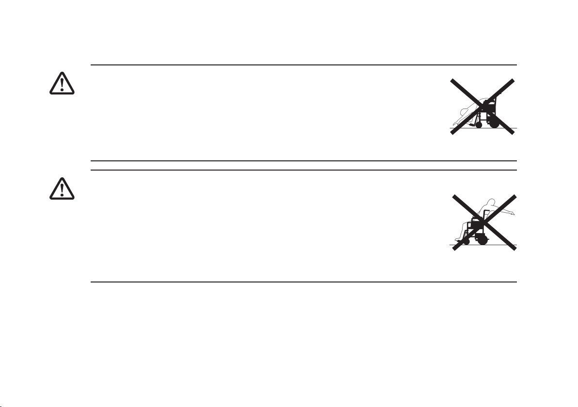
limitations. Due to both the weight of a powered wheelchair and it’s occupant it
is not advisable to attempt to be assisted up and down stairs whilst seated.
When entering or leaving your powerchair, DO NOT stand on the footplates.
If you have to brake in an emergency, release the joystick. DO NOT switch off
power while the powerchair is moving, it would cause an abrupt, sharp stop.
DO NOT use your powerchair beyond the limitations set out in this manual
concerning kerb height, gradients, etc.
Stability and Balance
To ensure stability and safe control of your powerchair you must at all times
maintain proper balance. The powerchair is designed to remain stable and
23
upright during normal use, so long as you do not move your centre of gravity outside the normal
seating position.
REACHING - BENDING FORWARD
•
Ensure power is OFF. DO NOT lean your body forward out of the
powerchair further than the length of the armrests.
•
DO NOT attempt to pick up objects from the floor by bending forward and
reaching between your knees.
•
DO NOT attempt to reach objects by sliding forward to the edge of the
Powerchair seat.
REACHING - BENDING BACKWARDS
•
Again ensure power is switched OFF.
•
DO NOT reach back any further than your arm will extend without changing
your sitting position.
•
DO NOT lean over the top of the backrest as it will shift the centre of gravity,
risking tipping over.
•
DO NOT hang heavy loads or objects on the backrest. They may make the powerchair
unstable, especially on an incline.
24
TRANSFERRING TO AND FROM OTHER SEATS
•
ALWAYS turn the wheelchair power OFF and engage the motor locks/clutches to prevent the
wheels from moving BEFORE attempting to transfer in or out of the wheelchair. Also, make
sure every precaution is taken to reduce the gap distance by turning both rear castors away
from the object you are transferring onto.
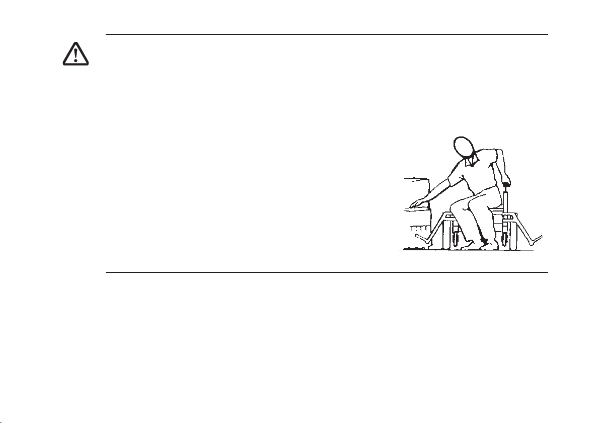
•
When transferring, position yourself as far back as possible in the seat. This will prevent broken
screws, damaged upholstery and the possibility of the
wheelchair tipping forward.
•
Note: This activity may be performed independently provided
you have adequate mobility and upper body strength.
•
Position the wheelchair as close as possible along side the
seat to which you are transferring, with the rear wheels
pointing away from it.
•
Engage motor locks/clutches.
•
Shift body weight into seat with transfer.
•
During independent transfer, little or no seat platform will be
beneath you. Use transfer board if at all possible.
25
NEGOTIATING GRADIENTS/SLOPES
•
Never attempt to climb or descend an incline where the surface is
rough, wet or slippery (gravel, loose chippings, grass, rain, black
ice, snow etc.).
•
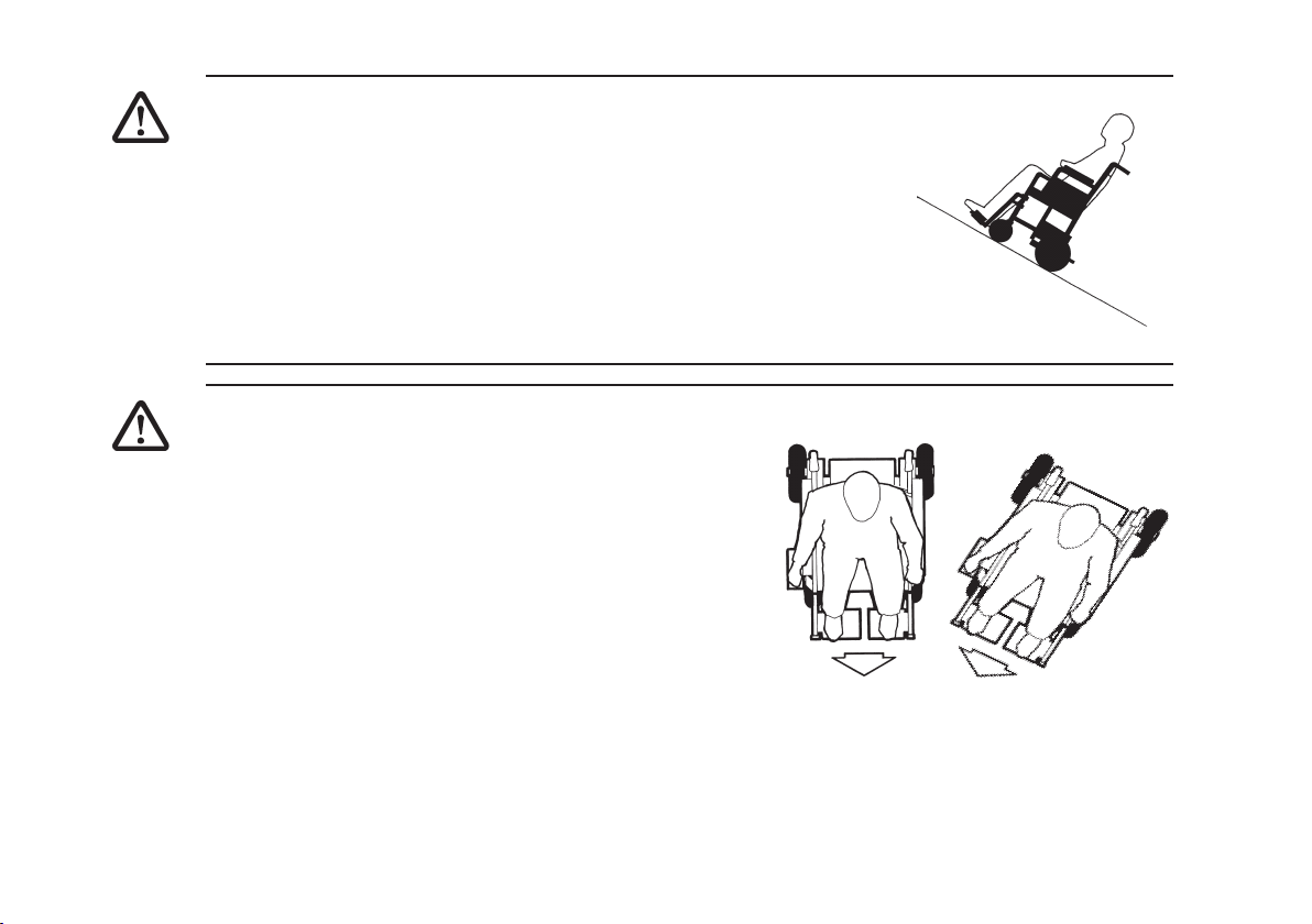
If you are in a situation where by the Powerchair fails to climb a
ramp and stalls midway through the manoeuvre, DO NOT attempt
to turn the Powerchair to drive back down in a forward facing
direction, always reverse slowly in a steady, flowing action and DO
NOT brake harshly, as this will upset balance in this situation. If
possible, always seek the assistance of an attendant.
NEGOTIATING KERBS
•
When approaching kerbs wherever possible mount
and dismount pavements via ramps. Always
approach the kerb head on, not at an angle.
•
When approaching a kerb stop approximately 5cm
from the kerb edge, then push the joystick firmly
forward and continue to climb over the obstacle in
one movement. DO NOT pause or attempt to steer
during this movement.
•
NOTE: Take care when mounting or dismounting a
kerb as it may be possible to lose drive if the antitipping castors contact the ground
33
3
33
2
Direction of Travel
26

YOU, YOUR POWERCHAIR AND OTHERS
•
Powerchairs are strictly forbidden on motorways and their use is strongly discouraged on highways with fast moving traffic.
•
On the Pavement, in Pedestrian Zones or in Supermarkets it is obvious that you must show as
much consideration and common sense to others as you expect from them.
•
When you cross the carriageway of a public road take extra care and allow time to cross,
observe the Highway code. Although you are not required by law to hold a driving license, you
are responsible and fully liable for proper operation. An important fact to bear in mind is that
you must not present a traffic hazard even in the event of a breakdown. The most common
cause may be discharged batteries. It is important to keep the batteries in a fully charged
condition, we can only repeat this warning at this stage. If you do suffer a breakdown for
whatever reason, you should immediately: seek the assistance of a passer-by. Explain where
to find the motor disengagement/declutching lever, ask him/her to switch to freewheel, so that
the Powerchair can be pushed by hand and moved. When in a safe place always ensure motor
gear boxes are re-engaged.
SAFEGUARDING OTHERS
•
We want you to get the most out of your INVACARE Powerchair, ensuring that the safety of
yourself and others is never in jeopardy. If you are in any doubt about safe techniques, handling
or care of the Powerchair, contact a recognised expert before putting yourself and others at risk.
27

4 Safety Inspection Checklist
Initial adjustments should be made to suit personal body structure/user capability and preference.
Thereafter follow these maintenance procedures:
inspect/ inspect/ inspect/
Item Initially adjust adjust adjust
weekly monthly periodically
General
Wheelchair rolls straight
(no excessive drag or pull to one side). X X
Motor brushes & motor gearbox coupling X
Clothing guards
Ensure all fasteners are secure. X X
Arms
Secure but easy to release;
adjustment handwheels engage properly. X X
Adjustable height arms operate
and lock securely. X X
Armrests
Inspect for rips in upholstery. X X
Arm rest pad sits flush against arm tube. X X
28

inspect/ inspect/ inspect/
Item Initially adjust adjust adjust
weekly monthly periodically
Seat and back upholstery
Inspect for rips or sagging. X X
Drive wheels
Axle nut and wheel mounting nuts are secure. X X X
No excessive side movement or binding when
lifted and spun when disengaged
(free-wheeling). X
Castors
Inspect wheel/fork assembly for proper tension
by spinning castor; castor should come to a
gradual stop. X X
Loosen/tighten locknut if wheel wobbles
noticeably or binds to a stop. X X
CAUTION: As with any vehicle, the wheels and
tyres should be checked periodically
for cracks and wear, and should be replaced.
Castor/wheel/fork/head tube
Ensure all fasteners are secure. X X
29

inspect/ inspect/ inspect/
Item Initially adjust adjust adjust
weekly monthly periodically
Tyres
Inspect for flat spots and wear. X X
If pneumatic tyres check for proper inflation. X X
CAUTION: As with any vehicle, the wheels
and tyres should be checked periodically for
cracks and wear, and should be replaced.
CLEANING
Clean upholstery and armrests. X X
NOTE:
Every six (6) months take your wheelchair to a qualified dealer for a thorough inspection and
servicing. Regular cleaning will reveal loose or worn parts and enhance the smooth operation of
your wheelchair. To operate properly and safely, your wheelchair must be cared for just like any
other vehicle. Routine maintenance will extend the life and efficiency of your wheelchair.
30

4.1 Troubleshooting - Mechanical
Chair Veers Sluggish Turn/ Castors Squeaks Solutions
Left/Right Performance flutter and Rattles
X X X If pneumatic, check tyres for correct
X X X X Check for loose stem nuts/bolts.
X X Check that both castors contact
Looseness In Chair Chair 3 Wheels Solutions
X If pneumatic, check tyres for correct and
X Check for loose stem nuts/bolts.
and equal pressure.
ground at the same time.
equal pressure.
31

4.2 Troubleshooting - Electrical
Symptom
Batteries draw excessive
current when charging.
Battery indicator flashes the
charge level is low immediately after recharge.
Battery indicator flashes the
charge level is low, too soon
after being recharged.
Motor “chatters” or runs
irregular.
Probable Cause
Battery failure.
Electrical malfunction.
Battery failure.
Malfunctioning battery
charger.
Electrical malfunction.
Batteries not charged.
Weak batteries.
Electrical malfunction.
Solutions
Check batteries for shorted cell.
Replace if necessary (see
section 10).
Contact Dealer/Invacare for
Service.
Check batteries for shorted cell.
Replace if necessary(see
section 10).
Contact Dealer/Invacare for
Service.
Poor connections between
charger and wheelchair. Contact
Dealer/Invacare.
Have charger checked.
Replace batteries if necessary.
Contact Dealer/Invacare for
Service.
Contact Dealer/Invacare for
Service.
32

Symptom
Probable Cause
Solutions
Only one (1) drive wheel
turns.
Joystick erratic or does not
respond as desired.
Electrical malfunction.
One motor lock is
disengaged.
Damaged motor coupling.
Electrical malfunction.
Contact Dealer/Invacare for
Service.
Engage motor lock (See section
11).
Contact Dealer/Invacare for
Service.
Contact Dealer/Invacare for
Service.
Wheelchair does not respond
to commands. Power
indicator OFF - even after
recharging.
Controller programmed
improperly.
Poor battery terminal
connection.
Electrical malfunction.
Contact Dealer/Invacare for
Service.
Clean terminals (see section
10 ).
Contact Dealer/Invacare for
Service.
Replace / Reset the fuse. (see
Blown / Tripped Fuse
section 10).
NOTE:
For additional troubleshooting information and explanation of electrical symptoms, refer to additional sections in this procedure of the manual.
33

4.3 Checking Battery Charge Level
The following “Do’s” and “Don’ts” are provided for your convenience and safety.
Don’ts
Don’t perform any installation or
maintenance without first reading this
manual.
Don’t make it a habit to discharge
batteries to the lowest level.
Don’t use randomly chosen batteries or
chargers.
Don’t put new batteries into service before
charging.
Don’t tap on clamps and terminals with
tools.
Don’t mismatch your battery and
chargers.
Do’s
Read and understand this manual and any service
information that accompanies a battery and charger
before operating the wheelchair.
Recharge as frequently as possible to maintain a
high charge level and extend battery life.
Follow recommendations in this manual when
selecting a battery or charger.
Fully charge a new battery before its first use.
Push battery clamps on terminals. Spread clamps
wider if necessary.
Use ONLY a GEL charger for a GEL or sealed
battery.
34

4.4 Care and maintenance
NOTE:
Have your vehicle checked once a year by an authorised Invacare dealer in order to maintain it’s
driving safety and roadworthiness.
Cleaning the vehicle
When cleaning the vehicle, pay attention to the following points:
• Only use a damp cloth and gentle detergent.
• Do not use any scrubbing agents.
• Do not subject the electronic components to any direct contact with water.
• Do not use high-pressure cleaning devices.
4.5 Product End of Life
Even though your Powerchair has been designed to provide a long and trouble free life it is inevitable
that wear, tear and usage will eventually render the product unusable.
• INVACARE recommends that the average usable life of this product is five years, providing
the product has been correctly maintained according to the manufacturers recommendations.
When the time comes to replace your Powerchair please remember to dispose of the product
responsibly and recycle any recycable parts as mentioned in this user guide.
35

5 Legrest Maintenance
WARNING:
•
After ANY adjustments, repair, or service and BEFORE use, make sure that all screws, nuts
and bolts are tightened securely - otherwise injury or damage may result.
•
It is important for regular inspection to be carried out on the Armrests for signs of visible
damage. If any repairs are required, these should be carried out by an INVACARE dealer.
5.1 Installing / Removing Legrests
1. Turn the Legrest to the side (open footplate is
perpendicular to wheelchair), locate holes on
legrest onto the pins.
2. Rotate the legrest towards the inside of the
wheelchair until it locks into place.
Lever
36
3. Ensure the release lever in engaged.
NOTE:
The footplate will be on the inside of the wheelchair when locked in place.
4. Repeat STEPS 1-3 for other legrest assembly.
Footplate Flip-up
Hanger Tube

Removing
1. To remove the legrest, push the release lever either upwards/downwards, rotate legrest outwards
and lift upwards.
5.2 Legrest height adjustment
1. Remove any accessory from the legrest(s).
2. Remove the legrest from the wheelchair. Refer to INSTALLING/REMOVING LEGRESTS in this
section of the manual.
NOTE:
Lay the footrest on a flat surface to simplify this procedure.
3. Loosen the legrest height adjustment screw using a
hex-wrench
4. Reposition the lower section (with foot plate) to the
desired height.
5. Tighten the legrest height adjustment screws. Ensure
the screws are secure.
6. Repeat STEPS 1-5 for the opposite side of the wheelchair legrest, if necessary.
Legrest stem
7. Reinstall the legrest(s) onto the wheelchair. Refer to
INSTALLING/REMOVING FOOTRESTS in this section
of the manual.
Height Adjustment Screws
37

5.3 Adjusting Angle Adjustable Flip-up Footplates
1. Locate the angle adjusting screw at the bottom of the legrest.
2. Loosen the screw with a hex wrench and adjust the foot plate to the desired angle and position.
3. Tighten the angle adjusting screw.
4. To adjust foot plate height, refer to LEGREST HEIGHT
ADJUSTMENT in this section of the manual.
Flip-up footplate
Angle adjustment screw
38
5.4 Adjusting / Replacing Foot Plate Heel Strap (if fitted)
Adjusting
1. Undo the hook and loop fastening strip and separate
the two sides.
2. Adjust to the desired position and fasten hook and
loop strips back together.
NOTE:
When adjusting the heel strap be sure to check that
your heel does not contact with the wheelchairs front
castors.
Footplate pegs
Strap
Replacing
1. Lift heel strap over footplate pegs and remove.
2. Using a screw driver, remove footplate peg fixing screws.
3. Replace with new footplate pegs and heel straps where necessary .
NOTE:
When replacing heel straps be sure to check that your heels do not contact with the wheelchair’s
front castors.
Fixing screw
39

6. Armrests
WARNING
•
After ANY adjustments, repair or service and BEFORE use, make sure that all attaching hardware is tightened securely - otherwise injury or damage may result.
•
It is important for regular inspection to be carried out on the Armrests for signs of visible
damage. If any repairs are required, these should be carried out by an INVACARE dealer.
6.1 Installing/Removing Armrests
WARNING
•
Make sure the armrest release and height adjustment handwheels are in the locked position
before using the wheelchair.
NOTE:
Be sure to fit the correct armrest on the corresponding side of the wheelchair.
Installing
1. Check the armrest removal handwheel is loose and not visible inside armrest socket.
2. Insert bottom of armrest tube into armrest socket and gently push down.
3. Turn armrest removal handwheel until tight and armrest is secure.
40
4. Repeat STEPS 1-3 for the opposite side armrest.
Removing
WARNING
•
Ensure joystick unit is switched off and unplugged from wheelchair before removing armrest.
•
Alternatively, remove joystick mounting arm from the armrest following instructions in section
12.3 JOYSTICK MOUNTING HARDWARE before attempting to remove armrest.
1. Turn armrest removal handwheel until loose.
2. Lift armrest up and out of the armrest socket.
3. Repeat STEPS 1-2 for the opposite armrest, if
necessary.
Removal
handwheel
41

6.2 Adjusting the Armrests
WARNING
•
Make sure the armrest release and height adjustment handwheels are in the locked position
before using the wheelchair.
Height Adjustment
1. Release the armrest height adjustment handwheel.
NOTE:
If the handwheel is released a small amount, an audible click can be heard when adjusting the
armrest height.
2. Slowly pull up or push down on the armrest top until the
desired height is achieved.
3. Tighten armrest height adjustment handwheel.
4. Repeat STEPS 1-3 for opposite armrest, if necessary.
Armpad Adjustment
1. Using a cross point screwdriver, loosen the armpad
fixing screws (located on underside of armpad).
2. Slide the armpad either forwards or backwards to the
desired position
Adjustment
handwheel
42

3. Tighten the armpad fixing screws.
4. Repeat STEPS 1-3 for opposite armrest, if necessary.
Armrest Width Adjustment
WARNING
•
This adjustment should only be performed when the wheelchair is unoccupied.
1. Using a hex wrench, loosen the armrest width adjustment screws.
2. Adjust the armrest position to give the desired width
by gently pulling the armrest away from the seat or
gently pushing the armrest towards the seat.
3. When adjustment is complete, tighten the armrest
width adjustment screws, ensuring they are secure.
4. Repeat STEPS 1-3 for opposite armrest, if
necessary.
Adjustment
screw
43
7 Backrest
WARNING
•
After ANY adjustments, repair or service and BEFORE use, make sure that all attaching
hardware is tightened securely - otherwise injury or damage may result.
•
It is important for regular inspection to be carried out on the Backrest for signs of visible
damage. If any repairs are required, these should be carried out by an INVACARE dealer.
•
It should be noted that under certain conditions and configuration of the wheelchair, i.e. for
users with limited / no lateral body control, and with the backrest in the reclined position, there
is the potential to creat a body trap between the armrest / side panel and the backrest. Suitable
accessories are available from Invacare (lateral trunk supports) to eliminate this risk.
7.1 Adjusting Backrest Angle
WARNING
•
This adjustment should only be performed when the wheelchair
is unoccupied.
•
Take care not to damage any accessories fitted to the backrest.
1. Remove the safety “R” clip from the end of the adjustment handwheel.
2. Unscrew handwheel from backrest.
3. Repeat steps 1 and 2 for opposite side.
Handwheel
44

4. Adjust backrest to desired angle.
5. Re-fit the handwheels to the available holes in the backrest. Hand tighten only.
6. Re-fit safety “R” clip.
7. Repeat steps 5 and 6 for opposite side.
7.2 Adjusting Backboard Position
WARNING
•
This adjustment should only be performed when the wheelchair is unoccupied.
•
Take care not to damage any accessories fitted to the backrest.
The backboard can be adjusted both in height and width (see section 8 Seating). This can be useful if
another type of back cushion is to be fitted.
1. Remove the four fixing screws using a cross point screwdriver.
2. Reposition the backboard.
3. Replace and tighten the four fixing screws.
NOTE:
Ensure the backboard is firmly secured before fitting the cushion or using the wheelchair.
45

7.3 Adjusting Backpost Support Bracket
CAUTION:
•
This adjustment should only be made by an attendant when the the chair is occupied.
The backpost support bracket can be adjusted in width. This should be used when adjusting seat and
backrest width (see section 8 Seating).
1. Release the set screws using a hex wrench.
2. Slide the seating and backrest to the desired width.
3. Re-tighten the set screws using a hex wrench
46
Set Screw

7.4 Installing / Removing or Adjusting Headrest (if fitted)
CAUTION:
•
After ANY adjustments, repair or service and BEFORE use, make sure that all attaching
hardware is tightened securely - otherwise injury or damage may result..
Installing
1. Ensure set screws are not protruding into headrest
support tube.
2. Insert headrest assembly into headrest support tube.
3. Tighten the set screws using a hex wrench.
Removal
1. Loosen the set screws using a hex wrench.
2. Remove headrest assembly from headrest support
tube.
Adjusting
1. Loosen the headrest nuts with a spanner.
2. Loosen the hand lever by turning anti-clockwise.
3. Adjust to desired position
4. Re-tighten nuts and hand lever.
Nuts
Hand Lever
Set Screws
Lateral Adjustment
Screws
Headrest
Support Tube
47

The lateral position of the headrest may also be adjusted as follows
1. Loosen the lateral adjustment screws using a hex wrench and spanner.
2. Slide the headrest assembly to the desired position.
3. Re-tighten the lateral adjustment screws.
NOTE:
Ensure all headrest assembly adjustment screws, nuts and hand levers are tightened before using
the wheelchair.
48

7.5 Installing / Removing or Adjusting Trunk Supports (if fitted)
CAUTION:
•
After ANY adjustments, repair or service and BEFORE use, make sure that all attaching
hardware is tightened securely - otherwise injury or damage may result..
Installing
1. Ensure the trunk support fixing screws are loose.
2. Slide the trunk support clamp over the fixing tube and hold at the desired position.
3. Tighten the trunk support fixing screws using a hex wrench.
Removal
1. Loosen the trunk support fixing screws using a hex
wrench and remove the trunk support assembly.
Adjusting
1. The trunk support height can be adjusted by
loosening the fixing screws and sliding the trunk
support to the desired location.
2. To adjust the trunk support position laterally, remove
the upholstered pad which is fixed using hook and
eye fasteners.
Tube
Clamping
screws
Clamp
Fixing screws
49

3. Loosen the clamping screws using a hex wrench.
4. Adjust to the desired position.
5. Tighten the clamp screws using a hex wrench and replace upholstered pad.
Swing away function
50
The trunk supports fitted to your Spectra Blitz
TM
have a swing away function to enable easier access
or transfer to and from the wheelchair
1. Firmly grip the trunk support near the fixing tube and pull upwards to disengage the internal
spring.
2. Swing the trunk support away from the seat.
3. To replace, swing the trunk support, back towards the seat and ensure it locates into position
CAUTION:
•
Ensure the trunk supports are firmly locked into position before using the wheelchair.

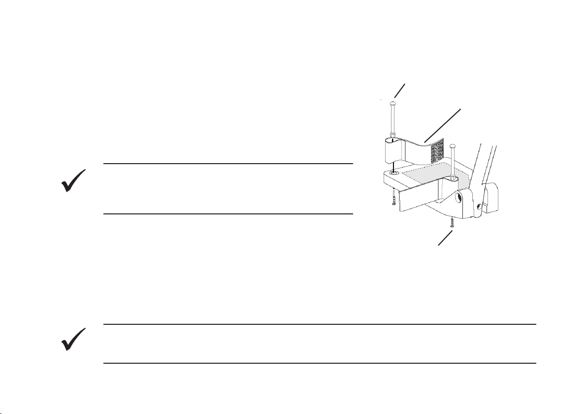
7.6 Adjusting Tension Adjustable Back Upholstery (if fitted)
CAUTION:
•
This adjustment should only be made when the the chair is unoccupied and the joystick unit
switched off.
1. Remove backrest cushion by releasing the hook and loop fastening strips.
2. Adjust the tension of each belt by releasing the hook and loop fastening strips and repositioning
as desired.
Backrest
CAUTION:
•
Be sure that each belt is secured before fitting
the back cushion and sitting in the chair.
3. Re-fit backrest cushion
Tension
Belts
Cushion
51

7.7 Installing / Removing Back Cushion
CAUTION:
•
This adjustment should only be made when the the chair is unoccupied and the joystick unit
switched off.
Installing / Removing
NOTE:
The cushion inner may be removed from the fabric cover by sliding it out from the cover flap on the
underside of the cushion.
1. Ensure the hook and loop fastener strip on the back is visible (remove covering strip if necessary,
or fitted).
2. Position the cushion on the back with the wedge shapes at the bottom and push down to secure.
3. To remove, pull up on cushion to release the hook and loop fastening. Remove cushion from back.
52

7.8 Adjusting Push Handles
CAUTION:
•
After ANY adjustments make sure that all attaching hardware is tightened securely - otherwise
injury or damage may result.
The push handles on your Spectra BlitzTM may be adjusted to a more convenient height to allow an
attendant to push or maneuver your Powerchair if required
1. Loosen the adjustment handwheel.
2. Raise or lower the push handles to the desired position.
3. Re-tighten the adjustment handle.
Push
Handle
Adjustment
Handwheel
53

8 Seating
WARNING
•
After ANY adjustments, repair or service and BEFORE use, make sure that all attaching
hardware is tightened securely - otherwise injury or damage may result.
•
It is important for regular inspection to be carried out on the Armrests for signs of visible
damage. If any repairs are required, these should be carried out by an INVACARE dealer.
8.1 Installing / Removing Seat Cushion
CAUTION:
•
This adjustment should only be made when the chair is unoccupied and the joystick unit
switched off.
Installing/Removing
NOTE:
The cushion inner may be removed from the nylon cover by sliding it out from cover flap on the
underside of the cushion.
1. Ensure the hook and loop fastener strip on the seat is visible (remove covering strip if necessary).
2. Position the cushion on the seat with the wedge shape end at the wheelchair front and push
down to secure.
54
3. To remove, pull up on cushion to release the hook and loop fastening. Remove cushion from
seat.

8.2 Lapbelt
WARNING
•
The standard lapbelt is NOT intended to be used as a vehicle seat belt.
A lapbelt is provided for use while seated in the power chair. INVACARE recommends that you keep
the lapbelt fastened at all times while seated in the chair. Buckles are fitted to each side of the belt
to allow for size adjustment.
8.3 Adjusting Seat Width
WARNING
•
This adjustment should only be performed when the wheelchair is unoccupied.
•
Take care not to damage any accessories fitted to the seat.
The seat can be adjusted in width. This can be useful if another type of seat cushion is to be fitted,
or to better accomodate the user.
WARNING
•
Before making the following adjustments ensure that the backpost support bracket
adjustment screws are loose (see section 7.3), and the backboard is removed (see section 7.2).
•
Failure to follow the above may result in damage to your Sectra BlitzTM seat.
1. Remove the seat cushion (see section 8.1).
55

2. Using a hex wrench loosen the adjustment screws .
3. Gently pull/push the side of the seat, until it
reaches the desired position.
4. Re-tighten the adjustment screws using a hex
wrench
5. Repeat for opposite side of chair.
6. Replace the seat cushion
NOTE:
Ensure the backboard is firmly secured before fitting the cushion or using the wheelchair.
8.4 Adjusting Seat Depth
WARNING
•
This adjustment should only be performed when the wheelchair is unoccupied.
•
Take care not to damage any accessories fitted to the seat.
The seat can be adjusted in depth. This can be useful if another type of seat cushion is to be fitted,
or to better accomodate the user.
Seat Frame Adjustment
1. Remove the seat cushion (see section 8.1).
56
Set Screw

2. Using a hex wrench loosen the adjustment screws.
3. Gently pull/push the side of the seat until it reaches the desired position.
4. Re-tighten the adjustment screws using a hex wrench.
5. Repeat for opposite side of chair.
Seat Board Adjustment
1. Remove the seat cushion (see section
8.1).
2. Using a cross point screwdriver loosen the
fixing screws.
3. Slide the seatboard until it reaches the
desired position.
4. Re-tighten the fixing screws using a cross
point screwdriver.
5. Replace the seat cushion.
Seatboard
Adjustment
Screw
Legrest
Adjustment
Screw
57

8.5 Installing / Removing Seat board
WARNING
•
This adjustment should only be performed when the wheelchair is unoccupied.
•
Take care not to damage any accessories fitted to the seat board.
The seat board can be removed from the wheelchair seat frame.
1. Remove the seat cushion (see section 8.1).
2. Remove the four fixing screws using a cross point screwdriver.
3. Install / Remove the seat board (if installing ensure that the holes on the under side of the seat
board are alligned with the slots in the seat frame).
4. Replace and tighten the four fixing screws using a cross point screwdriver.
NOTE:
Ensure the seat board is firmly secured before fitting the cushion or using the wheelchair.
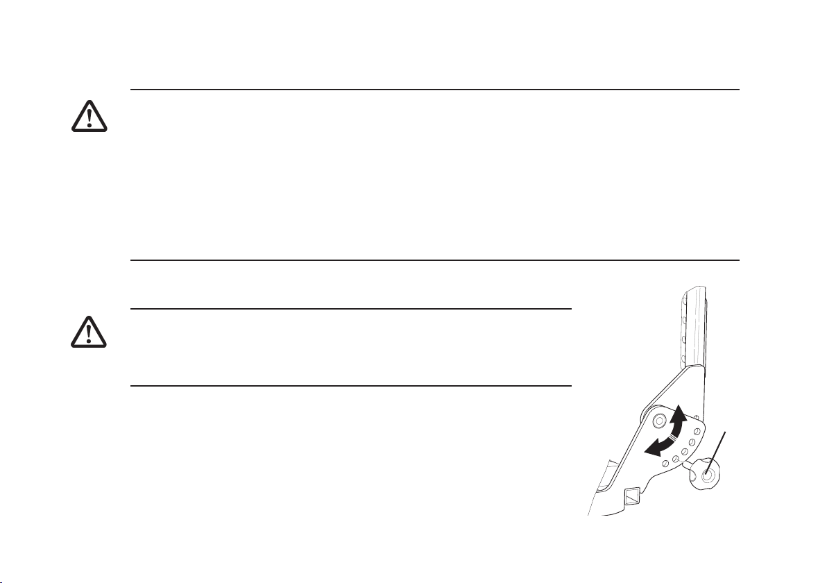
8.6 Adjusting Seat Angle
WARNING
•
This adjustment should only be performed when the wheelchair is on a flat, and horizontal
surace. Under no circumstances should this adjustment be made while the chair is in motion,
obstical climbing or stionary on a slope.
58

Electrical Adjustment of Seat Angle
If your Spectra BlitzTM power chair is fitted with an electrical seat angle adjustment refer to section
12 Controls and Operating your Powerchair or see the seperate control system user guide
1. Seat angle adjustment is made by operating the control system.
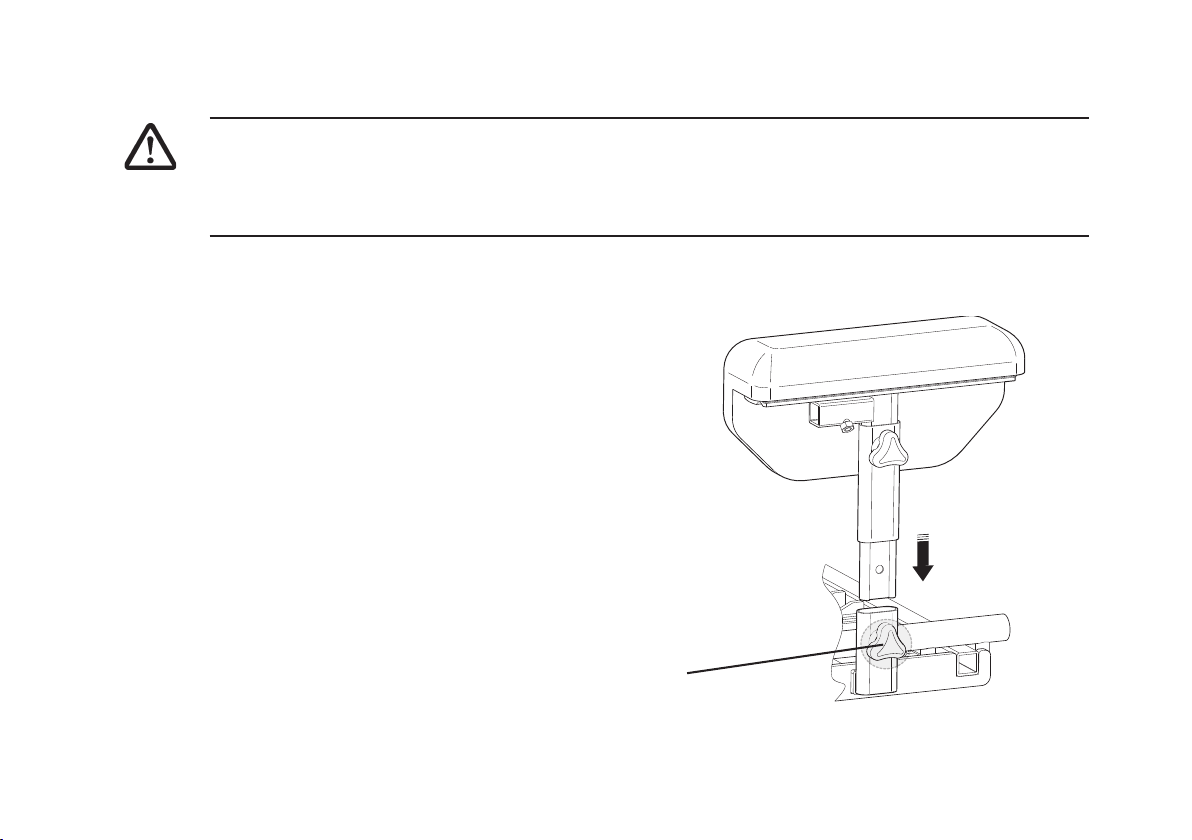
Manual Adjustment of Seat Angle
If your Spectra Blitz power chair is fitted with a manual seat angle adjustment refer
to the following to set the required seat angle:
1. Remove the M10 nut and bolt at the base of the assembly
2. Rotate the female (lower) assembly clockwise to increase the seat angle or
counter clockwise to decrease the seat angle
3. Once the desired seat angle is achieved replace the M10 nut and bolt, and
tighten the lock nut against the female assembly
WARNING
•
This adjustment should only be performed when the wheelchair is
unoccupied .
Lock Nut
Collar
59

9 Anti Tipping Castors
WARNING
•
After ANY adjustments, repair or service and BEFORE use, make sure that all attaching
hardware is tightened securely - otherwise injury or damage may result.
•
The Anti Tipping Castors are an important saftey feature of the Spectra BlitzTM wheelchair. DO
NOT attempt to drive the vehicle if they have been removed or damaged.
NOTE
•
Take care when mounting or dis-mounting a kerb. It may be possible to loose drive if the antitipping casters contact the ground.
60

10 Batteries
WARNING
•
Make sure power to the wheelchair is OFF before performing this procedure.
• The use of rubber gloves and chemical goggles is recommended when working with batteries.
•
Invacare strongly recommends that battery installation and battery replacement always be done
by a qualified technician.
•
After ANY adjustments, repair or service and BEFORE use, make sure all attaching hardware is
tightened securely - otherwise injury or damage may result.
•
This procedure MUST be performed while the wheelchair is unoccupied.
10.1 Removing/Installing Batteries
WARNING
•
Each battery can weigh up to 15kg. Use proper lifting techniques (lift with your legs) to avoid
injury.
•
Failure to use the correct battery size and/or voltage may cause damage to your wheelchair
and give you unsatisfactory performance.
•
Always use a battery lifting strap when lifting a battery. It also helps to prolong the life of the
battery.
The batteries fitted to your Invare Spectra BlitzTM are NOT designed to be removed frequently and
therefore the following procedure should only be carried out during service, repair of the wheelchair.
61

Removing
WARNING
•
NEVER allow any of your tools and/or battery cable(s) to contact BOTH battery terminal(s)/
post(s) at the same time. An electrical short may occur and serious personal injury or damage
may occur.
•
The use of rubber gloves and chemical goggles is recommended when working with batteries.
NOTE:
Perform this procedure on one (1) battery and battery box at a time. Repeat procedure for other
battery box.
1. Ensure the Joystick is switched off.
2. Remove the Rear Battery Cover.
3. Remove screws from front battery cover.
4. Remove the actuator from the fixing location under the seat.
5. Tilt the seat fully towards the rear of the chair.
62

6. Remove the front battery cover.
7. Remove all connectors from the controller.
8. Remove the screw that secures the NEGATIVE (-) black battery cable to the negative battery
terminal.
9. Remove the screw that secures the POSITIVE (+) red battery cable to the positive battery
terminal.
10. Detach the controller assembly from batteries.
11. Remove the battery retaining strap.
Rear Battery
12. Carefully remove each battery.
Front Battery
Negative (-)
Positive (+)
63

Installing
WARNING
•
NEVER allow any of your tools and/or battery cable(s) to contact BOTH battery terminal(s)/
post(s) at the same time. An electrical short may occur and serious personal injury or damage
may occur.
•
The use of rubber gloves and chemical goggles is recommended when working with batteries.
CAUTION
•
When connecting the battery cables to the battery(ies), the battery cable(s) MUST be connected
to the battery terminal(s)/post(s) depending on battery type. ALWAYS check the battery top for
POSITIVE (+) and NEGATIVE (-) marking symbols before connecting the battery cables.
1. Carefully place each battery into the tray (see figure).
2. Connect the battery retaining strap.
3. Attach the controller assembly.
4. Connect the battery cables to the battery terminals as follows:
Negative (-) BLACK battery cable to the NEGATIVE (-) battery terminal post;
Positive (+) RED battery cable to the POSITIVE (+) battery terminal post;
5. Secure the battery cables to the battery terminals, BLACK cable to NEGATIVE (-) and RED to
POSITIVE (+) with the provided fasteners. Securely tighten.
64

6. Connect the motor, joystick and actuator (if fitted) cables to the appropriate controller sockets.
7. Verify all cables are correctly installed and securely tightened.
8. Slide terminal caps onto battery terminals.
9. Attach front cover and fasten with screws provided.
10. Carefully lower the seat and securely fasten the actuator in position using the fasteners supplied.
11. Attach rear cover.
NOTE:
New Battery(ies) MUST be fully charged BEFORE using, otherwise the life of the battery(ies) will be
reduced.
65

10.2 Batteries and battery charging
IMPORTANT WARNINGS
•
The battery charger supplied with your powerchair is for indoor use only, it must be protected
from moisture and external heat sources.
•
Handle the battery charger with care, if it has been dropped or damaged, do not use it.
•
Do not use an extension lead for connection from the mains to the charger unless absolutely
necessary. If you do use one ensure it is in good condition.
•
Only use the charger supplied with your powerchair.
•
Batteries are heavy, if you have to remove them, ensure you adopt the correct lifting posture to
avoid injury. Ask for assistance if necessary.
Batteries
Your Powerchair is equipped with GEL type batteries (Acid free) which require only regular charging.
To ensure trouble free operation of your Powerchair it is imperative to monitor the battery charge
condition continuously and to recharge the batteries in good time.
Intervals at which the batteries may need charging will vary and depend upon the conditions in
which the Powerchair is being used, the weight of the user and ambient operating temperature in
which the Powerchair is being operated.
New batteries need charging before your first journey and will not perform to their peak until the first
six to ten charging cycles have been completed.
66

To ensure long battery life DO NOT allow your batteries to become totally discharged. If your Powerchair is not used for any length of time the batteries must receive a full charge once a month and
remain fully charged during storage.
For replacement batteries contact your local INVACARE supplier/dealer in order to ensure that the
new batteries are of the correct type and specification and are correctly installed and connected.
WHEN TO CHARGE
Keep an eye on the battery charge indicator on the joystick box at full charge all six lights will be on
(from right to left: green, amber, red). As the battery charge drops during Powerchair operation
successive lights will extinguish until eventually only the two red lights will be on. It means that you
must charge the batteries without delay. We strongly advise you, however, not to wait until this
critical point has been reached but to charge the batteries as early and as often as possible after
you have used your Powerchair. If you ignore the warning (only two red lights on), and the battery
charge drops further to a level where it is no longer sufficient to allow safe driving, the controller will
automatically cut the power supply to the motors, so that the Powerchair comes to an abrupt halt,
and you may find yourself stranded in an unpleasant situation.
Also, if you run down the batteries to such a low charge, you will have greatly reduced their potential service life.
Except in emergencies, NEVER drive on discharged batteries, this will add strain to them and
reduce their life.
We recommend batteries should be charged every time the Powerchair is used, independent of the
depth of discharge. Depending on this and their capacity, a full charge on completely discharged
batteries can take up to approximately eight hours.
67

CHARGING PROCEDURES
IMPORTANT
•
Before you attempt charging, ensure you read and understand the instruction manual supplied
with the Battery Charger.
To Charge Batteries:
• Check that the ventilation slots on the charger are clean and unobstructed.
• Plug the charger output lead into the socket on the joystick control box.
When charging is complete switch off and disconnect from the mains.
If required, the charger can be left connected to the Powerchair and to the mains. This will keep the
batteries 100% charged and compensate for self-discharging over a long period. (You cannot
overcharge your batteries).
If you experience charging difficulties or require further advice, do not hesitate to contact your local
INVACARE supplier/dealer.
• Connect the charger power supply cable to the mains socket and switch the power on. The
“Mains ON” and the “Charging” lights on the charger will come on.
• It is recommended the charger is left connected as described until the “Full Charge” light
illuminates to obtain optimum performance of the batteries.
68
• When the “Charge Complete” light illuminates, the batteries are fully charged and ready for
use.

NOTE
An "Overvoltage" condition may occur temporarily while you are descending a steep gradient with
fully charged batteries, when the motors virtually have the effect of a dynamo, adding to the
batteries.
WARNING
When you replace worn out batteries, fit the type recommended by the wheelchair manufacturer. If
you use another type the battery gauge may be inaccurate.
10.3 Disposing and Recycling of Used Batteries
You can help preserve our environment by returning your used rechargeable batteries to
the collection and recycling location nearest to you.
This product has been supplied from an environmentally aware manufacturer that
complies with the Waste Electrical and Electronic Equipment (WEEE)
Directive 2002/96/CE.
This product may contain substances that could be harmful to the environment if disposed of in places (landfills)
that are not appropriate according to legislation.
The ‘crossed out wheelie bin’ symbol is placed on this product to encourage you to recycle wherever possible.
Please be environmentally responsible and recycle this product through your recycling facility at its end of life.
NOTE
For further information on the location of your nearest battery recycling facility please contact your
local government authority.
69

11 Motor locks, Wheels and Brakes
WARNING
•
After ANY adjustments, repair or service and BEFORE use, make sure that all attaching
hardware is tightened securely - otherwise injury or damage may result.
CAUTION
•
As with any vehicle, the wheels and tyres should be checked periodically for cracks and wear,
and should be replaced.
11.1 Disengaging/Engaging Motor Lock
Levers
WARNING
•
DO NOT engage or disengage motor locks until the
power switch is in the OFF position.
1. Perform one (1) of the following:
• Engage (PUSH) - turn motor lock levers towards
the rear wheels.
• Disengage (DRIVE) - turn motor lock levers so
they are in line with wheel chair frame.
70

NOTE:
Motor lock disengagement/engagement allows free wheeling or joystick controlled operation. Free
wheeling allows an assistant to manoeuvre the wheelchair without power.
11.2 Adjusting Front Castors
1. Remove the headtube cover from the castor headtube.
2. To properly tighten castor journal system and guard against
flutter, perform the following check:
Cap
• Tip back the wheelchair to floor.
• Pivot both forks and castors to top of their arc simultane-
ously.
• Let castors drop to bottom of arc (wheels should swing
once to one-side, then immediately rest in a straight
downward position).
• Adjust locknuts according to freedom of castor swing.
3. Test wheelchair for manoeuvrability.
4. Readjust locknuts if necessary, and repeat STEPS 1-3 until
correct.
5. Snap headtube cover into the castor headtube.
Lock
Nut
Fork
71

11.3 Drive Wheels
Inflation.
1. Locate air valve and remove air cap.
2. Check the pressure rating marked on the side of the tyre and inflate as necessary.
NOTE:
The recommended inflation pressure is 40 PSI / 280 KPA / 2.8 Bar.
CAUTION
•
Do not over inflate tyres. As with any vehicle, the
wheels and tyres should be checked periodically for
wear.
Removal.
1. Release and remove the central screw using a hex
wrench.
2. Pull the wheel away from the chair. It may be
necessary to use some force.
CAUTION
•
If the wheel rim is to be spilt to change a tyre, it is
important that the bolts holding the rim are not
released if the tyre is pneumatic and inflated.
72

11.4 Manual Parking Brakes
To Activate Brake.
1. Locate the brake grip handle.
2. Push the brake handle towards the rear of the chair until it engages
3. Repeat for opposite side of chair.
To De-Activate Brake.
1. Locate the brake grip handle.
2. Pull the brake handle towards the front of
the chair until it disengages
3. Repeat for opposite side of chair.
CAUTION
•
Tyres must be correctly inflated for
maximum brake efficency.
Brake handle
Brake
Disengage
73

12 Controls and operating your powerchair
NOTE
Before you start using your Powerchair you must boost the battery charge by carrying out charging procedures as described in "Battery Charging" and always check the following:
1. Freewheel is engaged in drive Position.
2. Adjustments have been made to suit your individual needs and fasteners securely tightened.
3. Tyres are in good condition and correctly inflated. Or as specified on the Tyre Side Walls.
CAUTION
DO NOT use your Powerchair if the joystick boot shows any visible signs of damage. Please refer
to your INVACARE dealer regarding repairs.
12.1 Types of User Controller
Your Spectra BlitzTM Powerchair will be fitted with one of the controllers shown below. Please refer to
the relevant section of this user guide for basic operational instructions.
74
Shark
REM24SD Pilot +
VSI

Power On/Off
Fast
Joystick
Slow
Horn
Seat Function
12.2 Shark Operation
Seated in your Powerchair. Press the ON/OFF Switch. All battery gauge indicators will light briefly,
then either the current battery charge or lock mode will be indicated. The user can adjust the chair’s
top speed to suit their preferences and environment. The currently selected top speed is shown on
the Speedometer and can be adjusted using the “Increased Speed” (Hare) and “Decrease Speed”
(Tortoise) buttons. As already indicated, the electronic controller of your powerchair is programmable.
It means the way in which the Powerchair behaves can be changed and adjusted according to your
requirements and wishes. Contact your INVACARE supplier/dealer for programming requirments
Freewheel Operation (see 11.1)
To push the Powerchair by hand in the event of a fault or
battery failure, or simply to move it WITH NO OCCUPANT in
it, the two motor/gearbox units can be declutched from the
rear wheels. First ensure that power is switched OFF on the
joystick box.
CAUTION
•
Freewheel operation is only intended for short-term use
in SPECIAL CIRCUMSTANCES, NOT as a regular or
permanent mode of Powerchair movement. In freewheel
mode the Powerchair is NOT secured by the
electromagnetic brakes, as both brake systems are out
of action during this time.
75

12.3 Shark Controller Functions
The SHARK controller fitted to your Spectra BlitzTM power chair has several features and functions.
The following procedure shows how to use these.
Horn Button
Press the button once to sound the integrated horn.
LOCK Function
To lock the SHARK and prevent unauthorised use of your power chair perform the following.
1. Whilst power is on, press and hold the power button for four (4) seconds.
2. The dispaly will turn off immediately
3. After four (4) seconds all LED’s will flash briefly and the horn will sound a short beep. The power
chair will then turn off.
UNLOCK Function
1. Press the On button to turn the powerchair on.
2. All LED’s will flash briefly. The LED’s will then perform a slow right to left chase.
3. Press the Horn button twice before the LED chase is completed (approximately 10 seconds).
76
4. The battery charge level will then be displayed and the powerchair may now be operated normally.

Adjusting Driving Speed
There are five pre-set speeds already programmed into the Shark control. To change speed, press
the tortoise button to go slower or the hare button to go faster. The current speed is indicated in the
speedometer display.
Actuator Adjustment
To adjust the seat angle of your Powerchair press the seat function button once. The number 1 LED
will illuminate, move your joystick forward or backward to adjust seat angle. Once the desired seat
angle has been achieved press the seat function button twice to return to drive mode.
Using the Speedometer
The Speedometer is used to gauge the relative speed of the chair in comparison to the maximum
speed possible. The right-most LED indicates current maximum speed, which can be adjusted using
the Increase (Decrease) Speed button. Using the joystick, as the speed of the chair increases, the
LED’s will fill in until maximum speed (as displayed) is reached.
Battery Gauge
The battery gauge is used to indicate power and can also display the controller status shown in the
table. It displays battery charge, fault and status information from the SHARK controller.
77

Display
This means.....
Notes
All LEDs are off
All LEDs are on and steady
Left RED LED is flashing
Left to right LED chase
alternating with steady
display
All LEDs flashing slowly
Service indicator LED flashing
quickly
12.4 REM24SD Operation
See seperate user guide for detailed REM24SD operation.
Power is off
Power is on
Battery charge is low
Charging or programming
mode
Out of neutral at power up
detected.
Fault mode, abnormal condition on the chair
Less LEDs imply a reduced
battery charge
The batteries should be
charged as soon as possible
The steady LEDs indicate
the current charge level of the
batteries.
Release joystick back to
neutral
Contact your INVACARE supplier/dealer for assistance
78

12.5 Pilot + Operation
Seated in your Powerchair. Press the ON/OFF Switch. The battery gauge will blink then turn on after
second. Check the maximum speed control is set to a level which suits you. Push the joystick to
control the speed and direction of the wheelchair. Please note that if you push the joystick before or
just after you switch the control system on, the battery gauge will ripple up and down and the
wheelchair will not be allowed to move. You must release the joystick to resume normal operation. If
you do not release the joystick within five seconds the wheelchair will not be able to move, even if
you release the joystick and push it again. The battery gauge will then flash rapidly. You can reset
this condition by switching the control system off and on again. If you do not push the joystick as
you switch the wheelchair on and the battery gauge flashes rapidly, then
there may be a fault.
Freewheel Operation (see 11.1)
To push the Powerchair by hand in the event of a fault or battery
failure, or simply to move it WITH NO OCCUPANT in it, the two
motor/gearbox units can be declutched from the rear wheels.
First ensure that power is switched OFF on the joystick box.
CAUTION
•
Freewheel operation is only intended for short-term use in SPECIAL
CIRCUMSTANCES, NOT as a regular or permanent mode of Powerchair movement. In
freewheel mode the Powerchair is NOT secured by the electromagnetic brakes, as both brake
systems are out of action during this time.
Power On/Off
Mode
Information
Gauge
Horn
Joystick
79

12.6 Pilot + Controller Functions
The Pilot + controller fitted to your Spectra BlitzTM power chair has several features and functions.
The following procedure shows how to use these.
Horn Button
Press the button once to sound the intergrated horn.
Mode Button
Use the mode button to make speed adjustments or actuator movements as follows:
• Speed adjustment - Press mode button once, the speed display LEDs will flash. Push the
joystick left or right to increase or decrease the speed program (There are five speed settings,
Speed 1 is the lowest speed with one LED lit, Speed 5 is the highest speed with five LEDs lit).
When the desired speed has been selected either press the mode button twice or move the
joystick forward or backward to return to standard drive mode.
• Actuator adjustment - Press the mode button twice until the display shows the actuator LED
to be operated. Move the joystick forward or backward to operate the actuator. Once the
desired position has been acheived press the mode button once to return to drive mode.
Battery Gauge
If the battery gauge shows RED, YELLOW and GREEN, the batteries are charged. If the battery
gauges show just RED and YELLOW, then you should charge the batteries as soon as you can. If
the battery gauge shows just RED, either steady or flashing slowly, then you should charge the
batteries immediately.
80

System Status Indication
The system status indication is the primary source of user feedback. It displays battery charge, fault
and status information from the Pilot + controller.
The speed indicator is made up of five LEDs which indicate the programmed speed of the
wheelchair.
Display
All LEDs are off
LEDs are on and steady (battery gauge)
Battery gauge LEDs flash
slowly
Battery gauge LEDs step up
Battery gauge flashed once
every 2.5 seconds
Battery gauge flashes rapidly
This means.....
Power is off
Power is on
Battery charge is low
Charging or programming
mode
Control system has entered
sleep mode a period of inactivity.
Fault mode, abnormal condition on the chair
Notes
Less battery gauge LEDs imply a reduced battery charge
The batteries should be
charged as soon as possible
The steady LEDs indicate
the current charge level of the
batteries.
Turn off then turn back on
again.
Contact your INVACARE supplier/dealer for assistance
81

12.7 VSI Operation
Seated in your Powerchair. Press the ON/OFF Switch. The battery gauge will blink then turn on after
second. Check the maximum speed control is set to a level which suits you. Push the joystick to
control the speed and direction of the wheelchair. Please note that if you push the joystick before or
just after you switch the control system on, the battery gauge will ripple up and down and the
wheelchair will not be allowed to move. You must release the joystick to resume normal operation. If
you do not release the joystick within five seconds the wheelchair will not be able to move, even if
you release the joystick and push it again. The battery gauge will then flash rapidly. You can reset
this condition by switching the control system off and on again. If you do not push the joystick as
you switch the wheelchair on and the battery gauge flashes rapidly, then there may be a fault.
82
Information Gauge
Power On/Off
Freewheel Operation (see 11.1)
To push the Powerchair by hand in the event of a fault or battery
failure, or simply to move it WITH NO OCCUPANT in it, the two
motor/gearbox units can be declutched from the rear wheels.
First ensure that power is switched OFF on the joystick box.
Mode /Speed
Decrease
Horn
Mode / Speed
Increase
Joystick

CAUTION
•
Freewheel operation is only intended for short-term use in SPECIAL CIRCUMSTANCES, NOT
as a regular or permanent mode of Powerchair movement. In freewheel mode the Powerchair is
NOT secured by the electromagnetic brakes, as both brake systems are out of action during
this time.
12.8 VSI Controller Functions
The VSI controller fitted to your Spectra BlitzTM power chair has several features and functions. The
following procedure shows how to use these.
Horn Button
Press the button once to sound the intergrated horn.
LOCK Function
To lock the VSI and prevent unauthorised use of your Powerchair perform the following.
1. Whilst power is on, press and hold the power button. After one (1) second the system will beep,
now release the power button.
2. Move the joystick forward until the system beeps, then move the joystick backward until the
system beeps.
3. Now release the joystick, there will be a long beep. The wheelchair is now locked.
83

UNLOCK Function
1. Use the power button to switch the control system on. The speed indicator will be rippling up and
down.
2. Move the joystick forward until the joystick beeps, then move the joystick backward until the
control system beeps.
3. Release the joystick, the control system will beep. The control system is now unlocked.
Adjusting Driving Speed
There are five pre-set speeds already programmed into the VSI control. To change speed, press the
Speed Decrease button to go slower or the Speed Increase button to go faster. The current speed is
indicated in the speed profile display.
Actuator Adjustment
To adjust the seat angle of your Powerchair press the actuator mode button once. The LED indicator
will illuminate, move your joystick forward or backward to adjust seat angle. Once the desired seat
angle has been achieved press the seat function button once to return to drive mode.
Battery Gauge
The battery gauge is used to indicate power and can also display the controller status shown in the
table. It displays battery charge, fault and status information from the VSI controller. If the battery
gauge shows RED, YELLOW and GREEN, the batteries are charged. If the battery gauges show just
RED and YELLOW, then you should charge the batteries as soon as you can. If the battery gauge
shows just RED, either steady or flashing slowly, then you should charge the batteries immediately.
84

Display
This means.....
Notes
All LEDs are off
LEDs are on and steady (battery gauge)
Battery gauge LEDs flash
slowly
Battery gauge LEDs step up
Battery gauge flashed once
every 2.5 seconds
Battery gauge flashes rapidly
Power is off
Power is on
Battery charge is low
Charging or programming
mode
Control system has entered
sleep mode a period of inactivity.
Fault mode, abnormal condition on the chair
Less battery gauge LEDs imply a reduced battery charge
The batteries should be
charged as soon as possible
The steady LEDs indicate
the current charge level of the
batteries.
Turn off then turn back on
again.
Contact your INVACARE supplier/dealer for assistance
85

12.9 Driving practice
With the joystick you now control speed and direction of the Powerchair. The more you move it
forward, the faster you travel. To reverse, pull the joystick backward. By moving the joystick left or
right (while the Powerchair is moving forward or backward) you steer the Powerchair. Push the
joystick full left or right, and the Powerchair will turn around within its smallest turning circle. To slow
down, guide the joystick towards its centre (neutral) position. If you have to stop in an emergency,
simply release the joystick. It will automatically snap back to neutral and the Powerchair will come to
a smooth halt. As a last resort ONLY press the On/Off switch which will serve as an emergency off
switch. Once at a standstill, the Powerchair is instantly locked by the electromagnetic parking
brakes, so that it is perfectly safe while it is stationary, even on an incline.
12.10 Types of Attendant Controller
Your Spectra BlitzTM Powerchair may be fitted with one of the controllers shown below. Please refer to
the relevant section of this user guide for basic operional instructions.
NOTE
The REM24SD and the Shark joysticks may also be mounted as an attendant controls. Please refer
to the seperate REM24SD user guide for details or section 12.2 Shark Operation.
86
ACS Dual
Control
Pilot +
Attendant
Control
Pilot + Dual
Control

12.11 ACS Dual Control Operation
The Powerchair may be controlled by the user or by an attendant. Press the ON/OFF Switch on the
user control. All battery gauge indicators will light briefly, then either the current battery charge. The
Powerchair can then be switched between attendant or user control using the switch located on the
attendant control. The attendant can adjust the chairs speed using the speed dial and control
direction using the joystick. As already indicated, the electronic controller of your powerchair is
programmable. It means the way in which the Powerchair behaves can be changed and adjusted
according to your requirements and wishes. Contact your INVACARE supplier/dealer for programming
requirments
NOTE
Actuator can only adjusted from the user control.
Freewheel Operation (see 11.1)
To push the Powerchair by hand in the event of a fault or battery failure, or simply to move it WITH
NO OCCUPANT in it, the two motor/gearbox units can be declutched from the rear wheels. First
ensure that power is switched OFF on the joystick box.
CAUTION
•
Freewheel operation is only intended for short-term use in
SPECIAL CIRCUMSTANCES, NOT as a regular or permanent
mode of Powerchair movement. In freewheel mode the
Powerchair is NOT secured by the electromagnetic brakes, as
both brake systems are out of action during this time.
Joystick
User /
Attendant
Switch
Speed Dial
87

12.12 Pilot + Dual Control Operation
The Powerchair may be controlled by the user or by an attendant. Press the ON/OFF Switch on the
user control. Battery gauge indicators will light briefly, then either the current battery charge. The
Powerchair can then be switched between attendant or user control using the push button located on
the attendant control (mode is indicated by LED). The attendant can adjust the chairs speed using
the speed button and control direction using the joystick. As already indicated, the electronic
controller of your powerchair is programmable. It means the way in which the Powerchair behaves
can be changed and adjusted according to your requirements and wishes. Contact your INVACARE
supplier/dealer for programming requirments
NOTE
Actuator can only adjusted from the user control.
Freewheel Operation (see 11.1)
88
To push the Powerchair by hand in the event of a fault or battery
failure, or simply to move it WITH NO OCCUPANT in it, the two motor/
gearbox units can be declutched from the rear wheels. First ensure
that power is switched OFF on the joystick box.
CAUTION
•
Freewheel operation is only intended for short-term use in
SPECIAL CIRCUMSTANCES, NOT as a regular or permanent
mode of Powerchair movement. In freewheel mode the Powerchair
is NOT secured by the electromagnetic brakes, as both brake
systems are out of action during this time.
Joystick
Mode Selector
Speed
Selector

12.13 Pilot + Attendant Control
Press the ON/OFF Switch. The battery gauge will blink then turn on after second. Check the
maximum speed control is set to a level which suits you. Push the joystick to control the speed and
direction of the wheelchair. Please note that if you push the joystick before or just after you switch
the control system on, the battery gauge will ripple up and down and the wheelchair will not be
allowed to move. You must release the joystick to resume normal operation. If you do not release the
joystick within five seconds the wheelchair will not be able to move, even if you release the joystick
and push it again. The battery gauge will then flash rapidly. You can reset this condition by switching
the control system off and on again. If you do not push the joystick as you switch the wheelchair on
and the battery gauge flashes rapidly, then there may be a fault.
Freewheel Operation (see 11.1)
To push the Powerchair by hand in the event of a fault or battery
failure, or simply to move it WITH NO OCCUPANT in it, the two
motor/gearbox units can be declutched from the rear wheels.
First ensure that power is switched OFF on the joystick box.
CAUTION
•
Freewheel operation is only intended for short-term use in
SPECIAL CIRCUMSTANCES, NOT as a regular or permanent
mode of Powerchair movement. In freewheel mode the
Powerchair is NOT secured by the electromagnetic brakes, as
both brake systems are out of action during this time.
Joystick
Power On / Off
Mode / Speed
Button
89

12.14 Pilot + Attendant Controller Functions
The Pilot + controller fitted to your Spectra BlitzTM power chair has several features and functions.
The following procedure shows how to use these.
Mode Button
Use the mode button to make speed adjustments or actuator movements as follows:
• Speed adjustment - Press mode button once, the speed display LEDs will flash. Push the
joystick left or right to increase or decrease the speed program (There are five speed settings,
Speed 1 is the lowest speed with one LED lit, Speed 5 is the highest speed with five LEDs lit).
When the desired speed has been selected either press the mode button twice or move the
joystick forward or backward to return to standard drive mode.
• Actuator adjustment - Press the mode button twice until the display shows the actuator LED
to be operated. Move the joystick forward or backward to operate the actuator. Once the
desired position has been acheived press the mode button once to return to drive mode.
Battery Gauge
If the battery gauge shows RED, YELLOW and GREEN, the batteries are charged. If the battery
gauges show just RED and YELLOW, then you should charge the batteries as soon as you can. If
the battery gauge shows just RED, either steady or flashing slowly, then you should charge the
batteries immediately.
90

System Status Indication
The system status indication is the primary source of user feedback. It displays battery charge, fault
and status information from the Pilot + controller.
The speed indicator is made up of five LEDs which indicate the programmed speed of the
wheelchair.
Display
All LEDs are off
LEDs are on and steady (battery gauge)
Battery gauge LEDs flash
slowly
Battery gauge LEDs step up
Battery gauge flashed once
every 2.5 seconds
Battery gauge flashes rapidly
This means.....
Power is off
Power is on
Battery charge is low
Charging or programming
mode
Control system has entered
sleep mode a period of inactivity.
Fault mode, abnormal condition on the chair
Notes
Less battery gauge LEDs imply a reduced battery charge
The batteries should be
charged as soon as possible
The steady LEDs indicate
the current charge level of the
batteries.
Turn off then turn back on
again.
Contact your INVACARE supplier/dealer for assistance
91
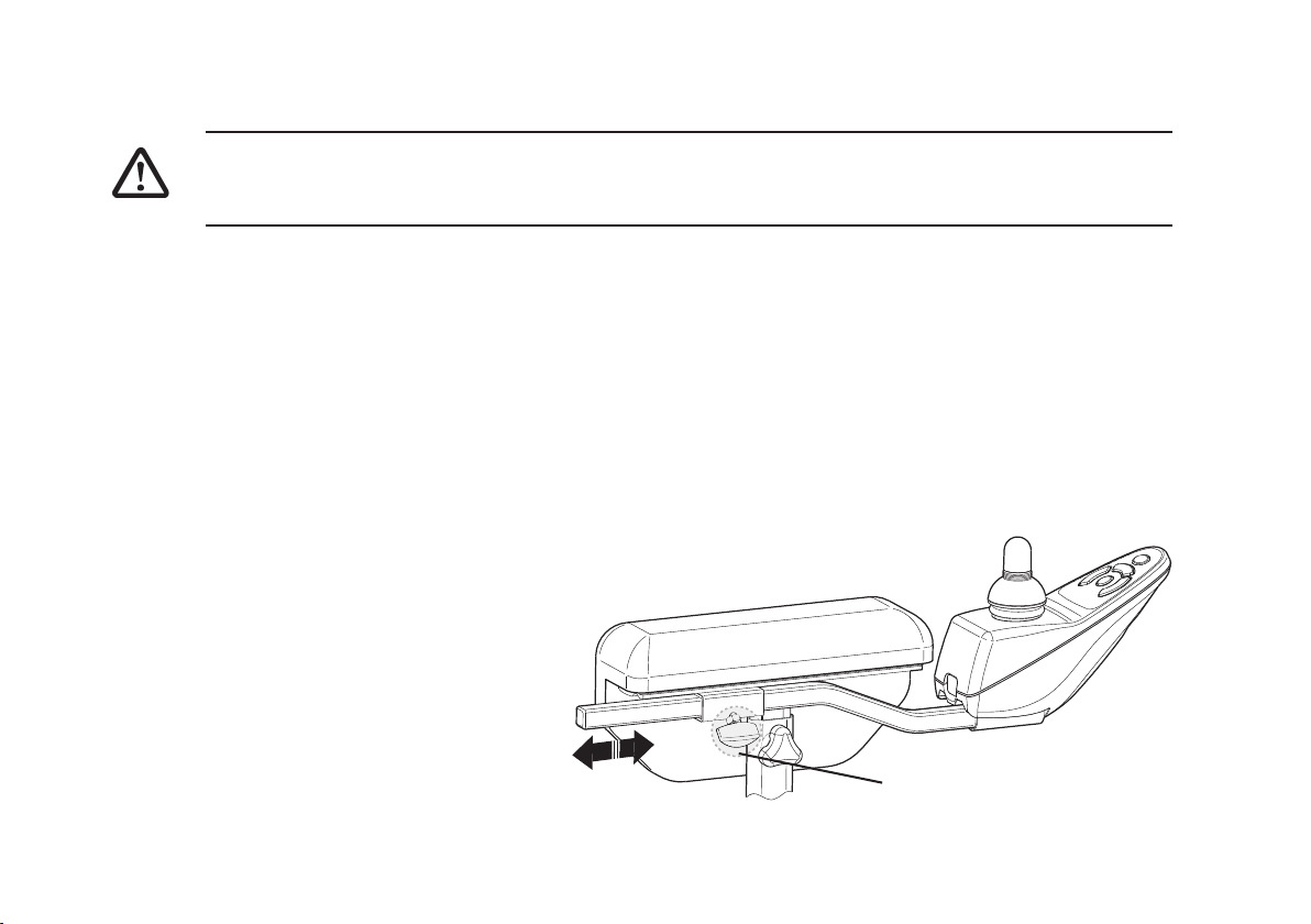
12.15 User Joystick Mounting Hardware.
WARNING
•
After ANY adjustments, repair or service and BEFORE use, make sure that all attaching
hardware is tightened securely - otherwise injury or damage may result.
Fixed Joystick Mounting Arm.
This type of mounting can move the joystick position either away from, or towards the armpad. This
can be set according to comfort and arm length as follows. There is no height adjustment other
than to vary the armrest height. See Section 6.2 Adjusting the Armrest.
Adjustment.
1. Unscrew the small handwheel located on the underside of the armrest.
2. Slide the Joystick to the desired position. Tighten small handwheel.
92
Adjustment handwheel

Installing / Removal.
1. Turn off the controller and unplug the controller communication cable (if applicable)
2. Unscrew the small handwheel located on the underside of the armrest.
3. Slide the joystick mounting arm through / into the clamping tube until it comes away / is at the
desired position.
4. If installing re-tighten small handwheel.
93

13 Transportation
CAUTION
INVACARE always advises that a Powerchair secured in a vehicle will not provide the equivalent
safety level and security as bespoke seating systems and recommends transfer to the vehicle
seating, but also recognises that it is not always practical for the user to be transferred.
In cases where transfer is not possible then the Powerchair should only be secured as follows:
NOTE
Your safety during transportation, largely depends upon the diligence of the person securing the
Tie-downs and passenger restraints, it is your responsibility to ensure that your Powerchair has
been secured safely.
1. The Spectra BlitzTM has been crash tested and has met all pass requirements of ISO 7176 Part
19 and is suitable for transportation with an occupant in a vehicle.
2. Seek confirmation from the transporter that the vehicle is suitably designed, insured and equipped
to transport a passenger seated in a Powerchair.
3. Any part of the Powerchair (accessories etc.) that can be easily detached should be removed and
stored in the vehicle luggage hold during transportation.
4. The Powerchair should always be transported in a forward facing direction. Rearward facing is
only acceptable if your head and back can be supported by a suitable bulkhead.
94

5. When attaching the tie-downs to the Powerchair, it is imperative they are fixed onto the Tie-Down
points only of the Powerchair and not onto any attachments or accessories, as shown below
(wheels, castors, footrests, armrests, anti-tipping levers etc.).
6. Your Spectra Blitz
TM
Powerchair MUST be fitted with a headrest and metal buckle lapbelt to be
used during transportation. For advice or to purchase these items contact Invacare or your local
dealer.
7. During transportation it is ESSENTIAL that you are secured by three point lap and diagonal
occupant restraint system, which is anchored to the vehicle wall and floor rails. Powerchair
lapbelts can be used in addition to the three point restraint system but must not be considered as
an alternative to the occupant restraint system.
Rear tie-down position
Front tie-down
bracket
95

8. Invacare recommend the Gemini System with 4-Point Heavy Duty Webbing Tie-Down System with
Karabiner should be used to secure your chair within the vehicle, these restraints are available
from Unwin Safety Systems (based in UK TA12 6EY, Tel: +44(0)1935 827740, http://www.unwinsafety.com).
The following system is recommended for use:
4 Point Gemini wheelchair tie down & occupant restraint system: G2
‘ D ’ Rings: DR
96

14 Technical Specifications
Seat Width Range: 250mm to 390mm
Seat Depth Range: 250mm to 380mm
Back Height Range: 370mm to 440mm
Back Angle Range: 85o to 120
Seatboard-to-Floor (approx.): 450mm @ 0
Overall Width of Base: 560mm
Overall Height: 910mm
Overall Length: 940mm
Weight Complete with Batteries: 79.5kg
Drive Wheels/Tyres: 335mm x 65mm (Foam Filled, Pneumatic or Solid)
Battery Type: 40Ah MK Batteries
Castors w/Precision Sealed Bearings 200mm x 46mm (Solid tyre)
o
o
97

Legrests: Swing-Away (Std), Angle Adjustment(Opt.), adjustable foot
plates (Opt)
Armrests: Adjustable Height, Removable.
A.S.B.A.* Seat Angle Adjustment: 3o Fixed
A.S.B.A.* Back Angle Adjustment: 9o Fixed (90o to 125o) Optional
A.S.B.A.* Seat Cushion: Cushion (Optional)
A.S.B.A.*
Chair Upholstery Options: Black Nylon, Two Way Stretch Fabric
A.S.B.A.* Accesories Headrest (optional) Lateral Supports (Optional)
Operating Temperature: -20oC to 50oC
Storage Temperature: -40oC to 65oC
Kerb Climbing: 50mm
Weight Limitations: 75kg (165lbs, 11.8 stone).
Performance Rating: 120kg Speed up to 6Kmph (4Mph) Range** up to 20Km (12 miles)
* A.S.B.A. Stands for Adjustable Seat and Back Angle.
98
**Range will vary with battery conditions, surface, terrain and operator’s weight.

15 Label locations
Battery Wiring Label
(inside battery boxes)
Emergency free
wheel device
label (motors)
Flammability Label
(upholstery)
Serial Label
99

European Headquarter:
Invacare International Sàrl, Route de Cité-Quest 2,
CH-1196 Gland
Tel: (41)(0)22 354 60 10, Fax (41)(0)22 354 60 11
hqeurope@invacare.com
Sales Units:
Belgium & Luxemburg:
Invacare nv, Autobaan 22, B-8210 Loppem
Tel: (32)(0)50 83 10 10, Fax: (32)(0)50 83 10 11
belgium@invacare.com
Danmark:
Invare AIS, Sdr. Ringvej 39, DK-2605 Brønby,
Tel: (45)(0) 36 90 00 00, Fax: (45)(0)36 90 00 01
denmark@invacare.com
Deutschland & Eastern Europe:
Invacare Aquatec, Alemannenstraße 10,D-88316I sny
Tel: (49)(0)75 62 00 0, Fax: (49)(0)75 62 7 00 66
info@invacare-aquatec.de
Ulrich Alber GmbH, Vor dem Weissen Stein 21, D-72461
Albstadt-Tailfingen
Tel:(49)(0)7432 2006 0, Fax:(49)(0)7432 2006 299
info@ulrich-alber.de
Eire:
Invacare Ireland, Unit 5 Seatown Business Campus,
Seatown Rd, Swords, Dublin - Ireland
Tel: (353) 1 8107084, Fax: (353) 1 8107085
eire@invacare.com
WWW.INV ACARE.CO.UK
España:
Invacare SA, c/Areny s/n, Polígon Industrial de Celrà,
E-17460 Celrà (Girona)
Tel:(34)(0)972 49 32 00, Fax:(34)(0)9724 932 20
contactsp@invacare.com
France:
Invacare Poirier SAS, Route de St Roch, F-37230 Fondettes
Tel:(33)(0)2 47 62 64 66, Fax:(33)(0)2 47 42 12 24
contactfr@invacare.com
Italia:
Invacare Mecc San s.r.l., Via dei Pini 62, I-36016 Thiene (VI)
Tel:(39)(0)0445 38 00 59, Fax:(39)(0)0445 38 00 34
italia@invacare.com
Nederland:
Invacare Mecc San s.r.l., Via dei Pini 62, I-36016 Thiene (VI)
Tel:(31)(0)318 695 757, Fax:(31)(0)318 695 758
mobility@invacare.com
care@invacare.com
Norge:
Invacare AS, Grensevingen 9, Postboks 6230,
Etterstad, N-0603 Oslo
Tel:(47)(0)22 57 95 00, Fax:(47)(0)22 57 95 01
norway@invacare.com
island@invacare.com
Österreich:
Mobitec Mobiliätchilfen GmbH, Herzog Odilostrasse 101
Tel:(43)6232 5535 0, Fax:(43)6232 5535 4
office@mobitec-austria.com, austria@invacare.com
Portugal:
Invacare Lda, Rua Senhora de Campanhã 105
P-4369-001 Porto
Tel:(351)(0)225 1059, Fax:(351)(0)225 1057 39
portugal@invacare.com
Sverige & Suomi:
Invacare AB, Fagerstagatan 9, S-163 91 Spanga
Tel:(46)(0)8 761 70 90, Fax:(46)(0)8 761 81 08
sweden@invacare.com
finland@invacare.com
Dolomite AB, Box 55, V.Götgatan 5, S-33421 Anderstorp
Tel:(46)(0)971 58 84 00, Fax:(46)(0)371 170 90
info@dolomite.se
Switzerland:
Mobitec Rehab AG, Benkenstrasse 260, CH-4108
Witterswil
Tel:(46)(0)61 487 70 80, Fax:(46)(0)61 487 70 81
office@mobitec-rehab.ch
switzerland@invacare.com
United Kingdom & Eire:
Invacare Ltd, South Road, Bridgend Industrial Estate,
UK-Bridgend CF31 3PY
Tel:(44)(0)1656 664 321, Fax:(44)(0)1656 667532
uk@invacare.com
eire@invacare.com
MSS Ltd, MSS House, Taffs Fall Road, Treforest
Industrial Estate,
UK-Cardiff CF37 5TT
Tel:(44)(0)1443 849 200 - Fax:(44)(0)1443 843 377
sales@medsys.co.uk
Blitz-V-01-UK 12/06
1484781
100
 Loading...