


Owner's Operator and Maintenance Manual
POWER TILT ONLY
FOR PRONTO M71
POWER WHEELCHAIRS
DEALER: THIS MANUAL MUST BE GIVEN
TO THE USER OF THE WHEELCHAIR.
AND M91
USER: BEFORE USING THIS WHEELCHAIR,
READ THIS MANUAL AND SAVE FOR
FUTURE REFERENCE.

WARNING
DO NOT OPERATE THIS EQUIPMENT
READING AND UNDERSTANDING THIS
MANUAL. IF YOU ARE UNABLE TO
WARNING
WITHOUT FIRST
WARNING
UNDERSTAND THE WARNINGS, CAUTIONS,
AND INSTRUCTIONS, CONTACT A
HEALTHCARE PROFESSIONAL, DEALER OR
TECHNICAL PERSONNEL IF APPLICABLE
BEFORE ATTEMPTING TO USE THIS
EQUIPMENT - OTHERWISE INJURY OR
DAMAGE MAY RESULT.
THE INITIAL SET UP OF THIS WHEELCHAIR
MUST BE PERFORMED BY A QUALIFIED
TECHNICIAN.
PROCEDURES OTHER THAN THOSE DESCRIBED
IN THIS MANUAL MUST BE PERFORMED BY A
QUALIFIED TECHNICIAN.
SAVE THESE INSTRUCTIONS
Power Tilt Only For M71 And M91. 2 Part No.1118362 Rev A

TABLE OF CONTENTS
TABLE OF CONTENTS
SPECIAL NOTES ............................................................................... 4
LABEL LOCATIONS .......................................................................... 5
SPECIFICATIONS ............................................................................. 6
PROCEDURE 1 - GENERAL GUIDELINES ........................................... 7
Safety/Handling Of Wheelchairs ........................................................................................................... 13
PROCEDURE 2 - SAFETY INSPECTION/TROUBLE SHOOTING ........... 17
Safety Inspection Checklist..................................................................................................................... 17
Troubleshooting......................................................................................................................................... 18
PROCEDURE 3 - SEAT ASSEMBLY .................................................. 19
Operating The Power Tilt Only ............................................................................................................ 1 9
Tilting The Seat Assembly ....................................................................................................................... 20
PROCEDURE 4 - CHARGING BATTERIES ........................................ 22
Charging Batteries ..................................................................................................................................... 22
PROCEDURE 5 - ADJUSTING SEAT ASSEMBLY -
QUALIFIED TECHNICIAN ONLY.................................................. 24
Adjusting The Seat Height ....................................................................................................................... 24
Adjusting The Seat Depth ....................................................................................................................... 26
WARRANTY ................................................................. BACK COVER
TABLE OF CONTENTS
Part No. 1118362 Rev A 3 Power Tilt Only For M71 and M91.

SPECIAL NOTES
SPECIAL NOTES
SPECIAL NOTES
WARNING/CAUTION notices as used in this manual apply to hazards or
unsafe practices which could result in personal injury or property damage.
NOTICE
THE INFORMATION CONTAINED IN THIS DOCUMENT IS SUBJECT
TO CHANGE WITHOUT NOTICE.
As a manufacturer of wheelchairs, Invacare endeavors to supply a wide variety
of wheelchairs to meet many needs of the end user. However, final selection of
the type of wheelchair to be used by an individual rests solely with the user and
his/her healthcare professional capable of making such a selection.
WHEELCHAIR TIE-DOWN RESTRAINTS AND SEAT POSITIONING
STRAPS
Invacare recommends that wheelchair users NOT be transported in vehicles
of any kind while in wheelchairs. As of this date, the Department of
Transportation has not approved any tie-down systems for transportation of a
user while in a wheelchair, in a moving vehicle of any type.
It is Invacares position that users of wheelchairs should be transferred into
appropriate seating in vehicles for transportation and use be made of the
restraints made available by the auto industry. Invacare cannot and does not
recommend any wheelchair transportation systems.
WARNING
THIS SEATING SYSTEM HAS BEEN CUSTOM DESIGNED AND WILL BE
ASSEMBLED TO THE WHEELCHAIR BASE BEFORE DELIVERY TO THE
USER. THE INFORMATION CONTAINED IN THIS MANUAL IS FOR
MAINTAINING AND ADJUSTING THE SEATING SYSTEM. THERE ARE
VERY FEW ADJUSTMENTS THAT CAN SAFELY BE MADE BY THE
USER. IF THERE IS A PROCEDURE OR ADJUSTMENT THAT NEEDS TO
BE PERFORMED ON THE SEATING SYSTEM THAT IS NOT IN THIS
MANUAL, DO NOT PERFORM THAT PROCEDURE. HAVE THE
SEATING SYSTEM SERVICED BY A QUALIFIED TECHNICIAN.
The drive behavior initially experienced by the user may be different from
other chairs previously used. This Power Wheelchair has Invacares Sure Step
technology, a feature that provides the chair with optimum traction and
stability when driving forward over transitions and thresholds of up to 2-inches
for the M71 and 3-inches for the M91. The following warnings apply specifically
to the Sure Step Feature.
l Do not use on inclines greater than 9o.
l Do not use on inclines with wet, slippery, icy or oily surfaces. This may
include certain painted or otherwise treated wood surfaces.
l Do not traverse down ramps at high speed. Doing so will reduce traction
and increase stopping distance.
l The end users weight can materially affect traction on sloped surfaces.
Great care should be taken when traversing such slopes.
To determine and establish your particular safety limits, practice use of this
product on various sloping surfaces in the presence of a qualified healthcare
provider BEFORE attempting active use of this wheelchair. Other general
warnings listed within this document also apply.
Power Tilt Only For M71 And M91. 4 Part No.1118362 Rev A
LABEL LOCATIONS
LABLE LOCATIONS
LABLE LOCATIONS
SPECIAL NOTES
Part No. 1118362 Rev A 5 Power Tilt Only For M71 and M91.

SPECIFICATIONS
NOTE: Refer to the wheelchair owner's manual for complete specifications on base and
operation.
Seat Width Range: 16 - 20-inches 16 - 22-inches
Seat Depth Range: 16 - 20-inches 16 - 22-inches
*Seat-to-Floor Height: 18-1/2 - 20-1/2-inches 20 -21-inches
SPECIFICATIONS
Overall Width:
Without Joystick: 24-inches 26-inches
With Joystick and TRSS: 26-inches 27-inches
Overall Height: 35-3/4 - 43-3/4-inches 37 - 45-inches
Over all Length with
Front riggings: 43-1/4-inches 44-inches
Back Height Range: 16 - 24-inches 16 - 24-inches
Back Angle Range (ASBA): 95° - 120° in 6-1/4° increments 95° - 120° in 6-1/4° increments
Tilt Range:
0° Seat Pan Angle: 0° - 45° 0° - 45°
5° Seat Pan Angle: 5°- 50° 5°- 50°
Turning Radius
With Front Riggings: 28-inches 27-1/2-inches
Maximum Speed: 3 MPH 6-1/2 MPH
Incline Capability: 9° 9°
Weight of Power Tilt Only: 45lbs. 45lbs.
Armrests: Adjustable Angle, Height, and Adjustable Angle, Height, and
Weight Limit of Wheelchair
With Power Tilt Only: 250lbs. 250lbs.
SPECIFICATIONS
M71 M91
(In 1/2-inch increments (in 1/2-inch increments)
Depth Depth
* NOTE: The seat-to-floor heights are based on 18-inch deep seat with 0° (+1°) seat pan angle and
pneumatic tires or flat free inserts. Seat-to-floor height measured from the front edge of seat to floor.
All heights are measured with properly inflated new tires. These heights can vary +1/4-inch due to tire
wear.
Power Tilt Only For M71 And M91. 6 Part No.1118362 Rev A

GENERAL GUIDELINES SECTION 1
This Procedure Includes the Following:
Controller Settings/Repair or Service Information
Operating Information
Safety/Handling of Wheelchairs
Label Location
CONTROLLER SETTINGS/REPAIR OR SERVICE
WARNING
Set-up of the Electronic Control Unit is to be performed ONLY by a
qualified technician. The final tuning adjustments of the controller may
affect other activities of the wheelchair. Reprogramming the controller
reduces the stability/controllability of the wheelchair. Other program
settings could cause the wheelchair to tip over resulting in serious injury to
the user and/or damage to the surrounding property. IF ANY
INDIVIDUAL OTHER THAN A QUALIFIED TECHNICIAN PERFORMS
ANY WORK ON THESE UNITS, THE WARRANTY IS VOID.
GENERAL GUIDELINES
OPERATING INFORMATION
GENERAL WARNINGS
Performance adjustments should only be made by professionals of the
healthcare field or persons fully conversant with this process and the
driver's capabilities. Incorrect settings could cause injury to the driver,
bystanders, damage to the chair and to surrounding property.
After the wheelchair has been set-up, check to make sure that the
wheelchair performs to the specifications entered during the set-up
procedure. If the wheelchair does NOT perform to specifications, turn the
wheelchair OFF immediately and reenter set-up specifications. Repeat this
procedure until the wheelchair performs to specifications.
ALWAYS shift your weight in the direction you are turning. DO NOT shift
your weight in the opposite direction of the turn. Shifting your weight in the
opposite direction of the turn may cause the inside drive wheel to lose
traction and the wheelchair to tip over.
DO NOT shift your weight or sitting position toward the direction you are
reaching as the wheelchair may tip over.
To determine and establish your particular safety limits, practice bending,
reaching and transferring activities in several combinations in the presence
of a qualified health professional BEFORE attempting active use of the
seating system/wheelchair.
DO NOT attempt to reach objects if you have to move forward in the seat.
DO NOT attempt to reach objects if you have to pick them up from the
floor by reaching down between your knees.
Part No. 1118362 Rev A 7 Power Tilt Only For M71 and M91.

SECTION 1 GENERAL GUIDELINES
DO NOT lean over the top of the back upholstery to reach objects from
behind as this may cause the seating system/wheelchair to tip over.
DO NOT operate the seating system while on an incline.
DO NOT operate the seating system while the wheelchair is moving.
NEVER operate the wheelchair while in any tilted position over 20
RELATIVE TO THE VERTICAL POSITION. If the drive lock-out does not
stop the wheelchair from operating in a tilt position 20o RELATIVE TO
THE VERTICAL POSITION, DO NOT operate the wheelchair. DO NOT
attempt to adjust the drive lock-out. Have the wheelchair serviced by a
GENERAL GUIDELINES
qualified technician.
DO NOT operate tilt seat around children.
Keep hands and feet out from underneath tilt seat - otherwise injury may
result.
DO NOT tip the seating system/wheelchair without assistance.
DO NOT store items under seat - interference with seat latch may result.
GENERAL WARNINGS
o
DO NOT use an escalator to move a seating system/wheelchair between
floors. Serious bodily injury may occur.
Before attempting to transfer in or out of the seating system/wheelchair,
every precaution should be taken to reduce the gap distance. Turn both
casters toward the object you are transferring onto. Also be certain the
power is OFF and wheel locks are engaged to prevent the wheels from
moving.
DO NOT engage or disengage the motor locks until the power is in the
OFF position.
DO NOT operate on roads, streets or highways.
DO NOT climb, go up or down ramps or traverse slopes greater than 9o.
DO NOT attempt to move up or down an incline with a water, ice or oil
film.
DO NOT attempt to drive over curbs or obstacles. Doing so may cause
your seating system/wheelchair to turn over and cause bodily harm or
damage to the seating system/wheelchair.
DO NOT use parts, accessories, or adapters other than those authorized
by Invacare. Otherwise, the warranty is void.
DO NOT leave the power ON when entering or exiting your seating
system/wheelchair.
Power Tilt Only For M71 And M91. 8 Part No.1118362 Rev A

GENERAL GUIDELINES SECTION 1
GENERAL WARNINGS
DO NOT attempt to lift the seating system/wheelchair by lifting on any
removable (detachable) parts. Lifting by means of any removable
(detachable) parts of a seating system/wheelchair may result in injury to the
user or damage to the seating system/wheelchair.
DO NOT stand on the frame of the seating system/wheelchair.
Anti-tippers MUST BE attached at all times.
DO NOT use the footplates as a platform. When getting in or out of the
seating system/wheelchair, make sure that the footplates are in the upward
position or swing footrests towards the outside of the seating system/
wheelchair.
ALWAYS wear your seat positioning strap.
GROUNDING INSTRUCTIONS
DO NOT, under any circumstances, cut or remove the round grounding
prong from any plug used with or for Invacare products. Some devices are
equipped with three-prong (grounding) plugs for protection against
possible shock hazards and fire. Where a two-prong wall receptacle is
encountered, it is the personal responsibility and obligation of the customer
to contact a qualified electrician and have the two-prong receptacle
replaced with a properly grounded three-prong wall receptacle in
accordance with the National Electrical Code. If you must use an extension
cord, use ONLY a three-wire extension cord having the same or higher
electrical rating as the device being connected. In addition, Invacare has
placed RED/ORANGE WARNING TAGS on some equipment. DO NOT
remove these tags.
GENERAL GUIDELINES
RAIN TEST
INVACARE has tested its power wheelchairs in accordance with ISO 7176
Part 9 Rain Test. This provides the end user or his/her assistant sufficient
time to remove his/her power wheelchair from a rain storm and retain
wheelchair operation.
DO NOT leave power wheelchair in a rain storm of any kind.
DO NOT use power wheelchair in a shower.
DO NOT store power wheelchair in a damp area for an extended period
of time.
Direct exposure to excessive rain or dampness may cause the chair to
malfunction electrically and mechanically; may cause the chair to
prematurely rust or may damage the upholstery.
Check to ensure that the red and black battery terminal caps are secured in
place, joystick boot is NOT torn or cracked where water can enter and that
all electrical connections are secure at all times.
DO NOT use the joystick if the boot is torn or cracked. If the joystick boot
becomes torn or cracked, replace IMMEDIATELY.
Part No. 1118362 Rev A 9 Power Tilt Only For M71 and M91.

SECTION 1 GENERAL GUIDELINES
WEIGHT TRAINING
Invacare DOES NOT recommend the use of its wheelchairs as a weight
training apparatus. Invacare wheelchairs have NOT been designed or tested as
a seat for any kind of weight training. If occupant uses said wheelchair as a
weight training apparatus, INVACARE SHALL NOT BE LIABLE FOR
BODILY INJURY AND THE WARRANTY IS VOID.
WEIGHT LIMITATION
The power tilt only weight limit is 250 lbs. reguardless of wheelchair weight
limit.
ELECTROMAGNETIC INTERFERENCE (EMI)
GENERAL GUIDELINES
CAUTION: IT IS VERY IMPORTANT THAT YOU READ THIS
INFORMATION REGARDING THE POSSIBLE EFFECTS OF
ELECTROMAGNETIC INTERFERENCE ON YOUR POWERED
WHEELCHAIR.
ELECTROMAGNETIC INTERFERENCE (EMI) FROM RADIO WAVE
SOURCES
Powered wheelchairs and motorized scooters (in this text, both will be
referred to as powered wheelchairs) may be susceptible to electromagnetic
interference (EMI), which is interfering electromagnetic energy (EM) emitted
from sources such as radio stations, TV stations, amateur radio (HAM)
transmitters, two way radios, and cellular phones. The interference (from
radio wave sources) can cause the powered wheelchair to release its brakes,
move by itself, or move in unintended directions. It can also permanently
damage the powered wheelchair's control system. The intensity of the
interfering EM energy can be measured in volts per meter (V/m). Each
powered wheelchair can resist EMI up to a certain intensity. This is called its
"immunity level." The higher the immunity level, the greater the protection.
At this time, current technology is capable of achieving at least a 20 V/m
immunity level, which would provide useful protection from the more
common sources of radiated EMI. This powered wheelchair model as shipped,
MKIV - RII electronics, has an immunity level of unknown.
There are a number of sources of relatively intense electromagnetic fields in
the everyday environment. Some of these sources are obvious and easy to
avoid. Others are not apparent and exposure is unavoidable. However, we
believe that by following the warnings listed, your risk to EMI will be minimized.
Power Tilt Only For M71 And M91. 10 Part No.1118362 Rev A

GENERAL GUIDELINES SECTION 1
ELECTROMAGNETIC INTERFERENCE (EMI)
The sources of radiated EMI can be broadly classified into three types:
1) Hand-held Portable transceivers (transmitters-receivers with the
antenna mounted directly on the transmitting unit. Examples include:
citizens band (CB) radios, "walkie talkie," security, fire, And police
transceivers, cellular telephones, and other personal communication
devices. **NOTE: Some cellular telephones and similar devices transmit
signals while they are ON, even when not being used;
2) Medium-range mobile transceivers, such as those used in police cars,
fire trucks, ambulances, and taxis. These usually have the antenna
mounted on the outside of the vehicle; and
3) Long-range transmitters and transceivers, such as commercial
broadcast transmitters (radio and TV broadcast antenna towers) and
amateur (HAM) radios.
NOTE: Other types of hand-held devices, such as cordless phones, laptop
computers, AM/FM radios, TV sets, CD players, cassette players, and small
appliances, such as electric shavers and hair dryers, so far as we know, are not
likely to cause EMI problems to your powered wheelchair.
GENERAL GUIDELINES
Part No. 1118362 Rev A 11 Power Tilt Only For M71 and M91.

SECTION 1 GENERAL GUIDELINES
POWERED WHEELCHAIR ELECTROMAGNETIC INTERFERENCE (EMI)
Because EM energy rapidly becomes more intense as one moves closer to
the transmitting antenna (source), the EM fields from hand-held radio wave
sources (transceivers) are of special concern. It is possible to
unintentionally bring high levels of EM energy very close to the powered
wheelchair's control system while using these devices. This can affect
powered wheelchair movement and braking. Therefore, the warnings listed
are recommended to prevent possible interference with the control
system of the powered wheelchair.
Electromagnetic interference (EMI) from sources such as radio and TV
stations, amateur radio (HAM) transmitters, two-way radios, and cellular
GENERAL GUIDELINES
phones can affect powered wheelchairs and motorized scooters. Following
the warnings listed below should reduce the chance of unintended brake
release or powered wheelchair movement which could result in serious
injury.
1) Do not operate hand-held transceivers (transmitters receivers), such
as citizens band (CB) radios, or turn ON personal communication
devices, such as cellular phones, while the powered wheelchair iS
turned ON;
2) Be aware of nearby transmitters, such as radio or TV stations, and try
to avoid coming close to them;
3) If unintended movement or brake release occurs, turn the powered
wheelchair OFF as soon as it is safe;
4) Be aware that adding accessories or components, or modifying the
powered wheelchair, may make it more susceptible to EMI (Note:
There is no easy way to evaluate their effect on the overall immunity
of the powered wheelchair); and
5) Report all incidents of unintended movement or brake release to the
powered wheelchair manufacturer, and note whether there is a source
of EMI nearby.
IMPORTANT INFORMATION
1) 20 volts per meter (V/m) is a generally achievable and useful immunity
level against EMI (as of May 1994) (the higher the level, the greater the
protection);
2) The immunity level of this product is unknown.
Power Tilt Only For M71 And M91. 12 Part No.1118362 Rev A

GENERAL GUIDELINES SECTION 1
SAFETY/HANDLING OF WHEELCHAIRS
Safety and Handling of the wheelchair requires the close attention of the wheelchair user as well
as the assistant. This manual points out the most common procedures and techniques involved in
the safe operation and maintenance of the wheelchair. It is important to practice and master these
safe techniques until you are comfortable in maneuvering around the frequently encountered
architectural barriers.
Use this information only as a basic guide. The techniques that are discussed on the following
pages have been used successfully by many.
Individual wheelchair users often develop skills to deal with daily living activities that may differ
from those described in this manual. Invacare recognizes and encourages each individual to try
what works best for him/her in overcoming architectural obstacles that they may encounter,
however, ALL WARNINGS and CAUTIONS given in this manual MUST be followed. Techniques
in this manual are a starting point for the new wheelchair user and assistant with safety as the
most important consideration for all.
STABILITY AND BALANCE
WARNING
ALWAYS wear your seat positioning strap.
To assure stability and proper operation of your wheelchair, you must at all times maintain proper
balance. Your wheelchair has been designed to remain upright and stable during normal daily
activities as long as you do not move beyond the center of gravity. DO NOT lean forward out of
the wheelchair any further than the length of the armrests.
GENERAL GUIDELINES
COPING WITH EVERYDAY OBSTACLES
Coping with the irritation of everyday obstacles can be alleviated somewhat by learning how to
manage your wheelchair. Keep in mind your center of gravity to maintain stability and balance.
While the walking beam allows to traverse up to a 2-inch (M71) or a 3-inch (M91) bump or
threshold, stopping after the wheels cross the bump poses a problem. The chair cannot reverse
over the bump at this point. Continue forward and then turn around.
While the M91 and M71 are designed for use
primarily in and around the home, the provider
should determine whether this chair is suitable
for the actual environment the chair will be
used.
Do not go down ramp at full speed. Some seat/back
positions will cause wheelchair to feel unstable.
CAUTION
Be aware of condition of ramp.
Traction will be diminished/
nonexistent on a slippery surface.
Proceed with caution.
Part No. 1118362 Rev A 13 Power Tilt Only For M71 and M91.

SECTION 1 GENERAL GUIDELINES
A NOTE TO WHEELCHAIR ASSISTANTS
When assistance to the wheelchair user is required, remember to use good body mechanics.
Keep your back straight and bend your knees whenever tilting wheelchair or traversing
curbs, or other impediments.
Also, be aware of detachable parts such as arms or the footboard. These must NEVER be
used to move the wheelchair or as lifting supports, as they may be inadvertently released,
resulting in possible injury to the user and/or assistant(s).
When learning a new assistance technique, have an experienced assistant help you before
attempting it alone.
LIFTING/STAIRWAYS
GENERAL GUIDELINES
DO NOT attempt to move an occupied power wheelchair between floors
using a stairway. Use an elevator to move an occupied power wheelchair
between floors. If moving a power wheelchair between floors by means of a
stairway, the occupant MUST be removed and transported independently of
the power wheelchair.
Extreme caution is advised when it is necessary to move an UNOCCUPIED
power wheelchair up or down the stairs. Invacare recommends using two (2)
assistants and making thorough preparations.
Make sure to use ONLY secure, nondetachable parts for hand-hold supports.
It is strongly recommended to lift the wheelchair only by the rear frame and
the front forks - otherwise injury or damage may occur.
DO NOT attempt to lift the wheelchair by any removable (detachable) parts.
Lifting by means of any removable (detachable) parts of a wheelchair may
result in injury to the user or damage to the wheelchair.
The weight of the wheelchair base with batteries and without the user is 318 lbs.
Use proper lifting techniques (lift with your legs) to avoid injury.
Follow this procedure for moving the wheelchair between floors when an elevator is NOT
available or lifting the wheelchair is necessary:
NOTE: When using a stairway to move the wheelchair, seat and any accessories, move all wheelchair
components away from the stairway prior to reassembly.
WARNING
1. Remove the occupant from the wheelchair.
2. Remove the front riggings and any accessories.
3. Bend your knees and keep your back straight.
4. Using the rear frame and the front edge of the front forks as hand hold supports, transfer
the wheelchair base to desired location.
5. Using non-removable (nondetachable)
parts, transfer the seat and any accessories to desired location.
6. Reassemble the wheelchair.
Rear Frame
ESCALATORS? SORRY!
DO NOT use an escalator to move a
wheelchair between floors. Serious
bodily injury may occur.
Power Tilt Only For M71 And M91. 14 Part No.1118362 Rev A
Front Forks (Front Edge)

GENERAL GUIDELINES SECTION 1
TRANSFERRING TO AND FROM OTHER SEATS
WARNING
ALWAYS turn the wheelchair power OFF and engage the Motor Release
Levers to prevent the wheels from moving BEFORE attempting to transfer in
or out of the wheelchair. Also, make sure every precaution is taken to reduce
the gap distance by aligning both the front AND rear casters parallel with the
object you are transferring onto.
CAUTION
When transferring, position yourself as far back as possible in the seat. This
will prevent broken screws, damaged upholstery and the possibility of the
wheelchair tipping forward.
NOTE: This activity may be performed independently provided you have adequate mobility and upper
body strength.
1. Position the wheelchair as close as
possible along side the seat to which
you are transferring, with the rear
casters pointing away from it.
2. After the wheelchair is positioned
properly for transfer, verify that the
Motor Release Levers are engaged.
Refer to
ING MOTOR RELEASE LEVERS in
the owner's manual shipped with
wheelchair.
ENGAGING/DISENGAG-
MINIMIZE GAP
DISTANCE
GENERAL GUIDELINES
3. Flipback or remove arm on side of
wheelchair you are transferring
from.
4. Shift body weight into seat with transfer.
During independent transfer, little or no seat platform will be beneath you. Use a transfer
board if at all possible.
PERCENTAGE OF WEIGHT DISTRIBUTION
WARNING
DO NOT attempt to reach objects if you have to move forward in the seat or
pick them up from the floor by reaching down between your knees.
Many activities require the wheelchair user to reach, bend and transfer in and
out of the wheelchair. These movements will cause a change to normal
balance, center of gravity, and weight distribution of the wheelchair. To
determine and establish your particular safety limits, practice bending, reaching and transferring activities in several combinations in the presence of a
qualified healthcare professional BEFORE attempting active use of the wheelchair.
Proper positioning is essential for your safety. When reaching, leaning, bending or bending forward, it is important to use the casters as a tool to maintain
stability and balance.
Part No. 1118362 Rev A 15 Power Tilt Only For M71 and M91.

REACHING, LEANING, BENDING
AND BENDING - FORWARD
Position the front AND rear casters so that
they are extended as far rearward as possible
and engage Motor Release Levers.
DO NOT attempt to reach objects if
you have to move forward in the seat
or pick them up from the floor by
reaching down between your knees.
GENERAL GUIDELINES
REACHING, BENDING - BACKWARD
DO NOT lean over the top of the back upholstery. This will change your
center of gravity and may cause you to tip over.
GENERAL GUIDELINESSECTION 1
WARNING
WARNING
Position wheelchair as close as possible to the desired object. Point the front AND rear
casters rearward to create the longest possible wheelbase. Reach back only as far as your arm
will extend without changing your sitting position.
Power Tilt Only For M71 And M91. 16 Part No.1118362 Rev A

SAFETY INSPECTION/TROUBLESHOOTINGPROCEDURE 2
This Procedure Includes the Following:
Safety Inspection Checklist
Troubleshooting Guide
SAFETY INSPECTION CHECKLIST
Initial adjustments should be made to suit your personal body structure and preference.
Thereafter follow these maintenance procedures.
NOTE: Refer to the wheelchair owner's manual for a complete safety inspection checklist on the base.
ITEM INITIALLY INSPECT/ INSPECT/
ADJUST ADJUST
MONTHLY PERIODICALLY
ELECTRICAL CONNECTIONS
l Make sure all electrical connections are secure. X X
l Check limit switch position. X X
DRIVE LOCK-OUT
l Make sure drive lock-out operates properly. X X
TILT MECHANISM
l Make sure actuator operates smoothly and
properly. X X
l Make sure actuator mechanism and tilt tracks are
clean. X X
CLOTHING GUARDS
l Ensure all fasteners are secure. X X
ARMS
l Secure but easy to release; adjustment levers
engage properly. X X
l Adjustable height arms operate and lock securely. X X
ARMRESTS
l Inspect for rips in upholstery. X X
l Armrest pad sits flush against arm tube. X X
SEAT AND BACK CUSHIONS
l Inspect for rips. X X
CLEANING
l Clean cushions and armrests. X X
SAFETY INSPECTION
TROUBLESHOOTING
NOTE: Every six (6) months or as necessary take your wheelchair to a qualified dealer for a thorough
inspection and servicing. Regular cleaning will reveal loose or worn parts and enhance the smooth
operation of your wheelchair. To operate properly and safely, your wheelchair must be cared for just
like any other vehicle. Routine maintenance will extend the life and efficiency of your wheelchair.
Part No. 1118362 Rev A 17 Power Tilt Only For M71 and M91.

SAFETY INSPECTION/TROUBLESHOOTING
SECTION 2
TROUBLESHOOTING
NOTE: Refer to the wheelchair owner's manual for complete mechanical and electrical troubleshooting
guides on the base.
NOTE: Refer to the individual CONTROLLER MANUAL supplied with each wheelchair for additional
troubleshooting information and explanation of error codes.
SYMPTOM PROBABLE CAUSE SOLUTIONS
Wheelchair Power ON but
does not drive.
Seating system not functioning.
GENERAL GUIDELINES
System tilted beyond drive lockout angle.
Low Batteries.
Faulty electrical connection.
Blown Fuse.
Tilt to neutral (upright)
position. Contact Dealer/
Invacare for Service.
Charge batteries.
Check all connections.
Replace fuse.
TROUBLESHOOTING
Power Tilt Only For M71 And M91. 18 Part No.1118362 Rev A

SEAT ASSEMBLY SECTION 3
This Procedure Includes the Following:
Operating The Power Tilt Only
Tilting The Seat Assembly
OPERATING THE POWER TILT ONLY (FIGURE 1)
WARNING
NEVER operate the wheelchair while in any tilted position over 20o RELATIVE TO THE VERTICAL POSITION. If the drive lock-out does not stop the
wheelchair from operating in a tilt position 20
CAL POSITION, DO NOT operate the wheelchair. Have the wheelchair
serviced by a dealer or qualified technician.
A NOTE ABOUT DRIVE LOCK-OUT
Drive lock-out is a feature designed to prevent the wheelchair from being driven after the
seating system has been tilted beyond 20
activated, the LED on the single function toggle switch will light.
*NOTE: 20
NOTE: The tilt range is from 0
o
of tilt can be any combination of back angle and tilt.
o
to 45o with a 0o seat-to- floor angle and 5o to 50o with a 5o seat-to-floor
angle.
o
*. When the drive lock-out feature has been
INCREASING THE TILT ANGLE
o
RELATIVE TO THE VERTI-
SEAT ASSEMBLY
1. Make sure the wheelchair is on a level surface.
2. Push the single function toggle switch forward towards the front of the wheelchair until
the desired angle is achieved.
DECREASING THE TILT ANGLE
1. Pull the single function toggle switch back towards the rear of the wheelchair until the
desired angle is achieved.
Tilt
Single Function
Toggle Switch
FIGURE 1 - OPERATING THE TILT FUNCTION
Part No. 1118362 Rev A 19 Power Tilt Only For M71 and M91.

SECTION 3
SEAT ASSEMBLY
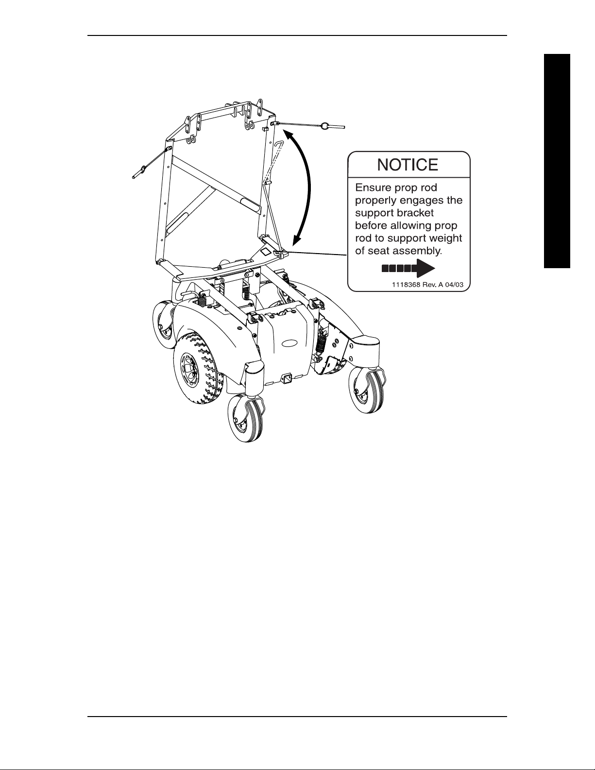
TILTING THE SEAT ASSEMBLY (FIGURE 2)
NOTE: Removing the seat is not necessary to access to the battery compartment on wheelchairs
equipped with a power tilt only seating system. The seat assembly with power tilt only tilts back and
propped in place to provide access to the batteries and underside of the seat.
WARNING
Make sure power to the wheelchair is OFF before performing this procedure.
NEVER leave the seat assembly in the UP/OPEN position unless necessary to
preform a procedure on the wheelchair - otherwise injury or damage may
result.
SEAT ASSEMBLY
After ANY adjustments, repair or service and BEFORE use, make sure all
attaching hardware is tightened securely - otherwise injury or damage may
result.
TILTING THE SEAT ASSEMBLY BACK
1. Place the wheelchair in a well ventilated area where work can be performed without risking
2. Verify the joystick ON/OFF switch is in the OFF position and disconnect joystick cable.
3. Remove front rigging. Refer to owner's manual shipped with wheelchair.
4. Remove the two (2) detent pins securing the power tilt only frame to the front seat
5. Firmly grasp the front edge of the seat assembly, slowly tilt the seat assembly BACK into
6. Remove prop rod from the clip located on the power tilt only frame and engage the prop
7. Gently allow weight of seat assembly to be supported by the prop rod.
NOTE: Only leave the Seat assembly in the UP/OPEN position while performing any necessary procedures. Always lower the seat assembly to the DOWN/CLOSED position when not servicing the wheelchair.
damage to carpeting or floor covering.
posts as shown in DETAIL "A" OF FIGURE 2.
the UP/OPEN position.
rod end in to the support bracket and shown in DETAIL "B" OF FIGURE 2.
TILTING THE SEAT ASSEMBLY FORWARD
1. Using one hand, firmly grasp the front edge of the seat assembly and lift until seat assembly is no longer supported by the prop rod.
2. Disengage prop rod from the support bracket and secure into clip as shown in DETAIL
"B" of FIGURE 2.
3. Using both hands, slowly tilt the seat assembly FORWARD into the DOWN/CLOSED
position.
WARNING
Ensure the two (2) detent pins are fully engaged and the power tilt only frame
is securely locked in place before use - otherwise injury or damage may result.
4. Insert the two (2) detent pins through both the power tilt only frame and the two (2)
front seat posts as shown in DETAIL "A" of FIGURE 2.
Power Tilt Only For M71 And M91. 20 Part No.1118362 Rev A

SEAT ASSEMBLY SECTION 3
DETAIL "A"
Detent
Pin
Seat Assembly (Front Edge)
Power Tilt Only
Frame
SEAT ASSEMBLY
Front
Seat
Posts
DETAIL "B"
Clip
Detent Pin
Detent Pin
Power Tilt
Only Frame
UP/OPEN
POSITION
DOWN/CLOSED
POSITION
Prop Rod
Bracket
FIGURE 2 - TILTING THE SEAT ASSEMBLY
Part No. 1118362 Rev A 21 Power Tilt Only For M71 and M91.

SECTION 4
This Procedure Includes the Following:
Charging Batteries
CHARGING BATTERIES
NEVER attempt to recharge the batteries by attaching cables directly to the
battery terminals.
DO NOT attempt to recharge the batteries and operate the wheelchair at the same time.
DO NOT attempt to recharge the batteries when the wheelchair has been
SEAT ASSEMBLY
exposed to ANY type of moisture.
DO NOT attempt to recharge the batteries when the wheelchair is outside.
DO NOT sit in the wheelchair while recharging the batteries.
READ and CAREFULLY follow the manufactures instructions for each
charger (supplied or purchased). If charging instructions are not supplied,
consult a qualified technician for proper procedures.
New batteries MUST be fully charged prior to initial use of the wheelchair.
SEAT ASSEMBLY
WARNING
CAUTION
ALWAYS charge new batteries before initial use or battery life will be reduced.
As a general rule, you should recharge your batteries as frequently as possible to assure the
longest possible life and to minimize required charging time. Plan to recharge them when
you do not anticipate using the wheelchair.
There are some basic concepts which will help you understand this automatic
process.
The amount of electrical current drawn within a given time to charge a battery is called charge
rate. If, due to usage, the charge stored in the battery is low, the charge rate is high. As a charge
builds up, the charge rate is reduced, and the battery charger rate decreases to a "trickle charge".
NOTE: If the batteries need to be charged more often or take longer to charge than normal, they may need
to be replaced. Contact a qualified technician.
NOTE: The batteries can be charged using the on-board battery charger OR by plugging an independent
battery charger into the port located on the front of the MKIV joystick.
BATTERY CHARGER OPERATION
WARNING
READ and CAREFULLY follow the manufactures instructions for each
charger (supplied or purchased). If charging instructions are not supplied,
consult a qualified technician for proper procedures.
NEVER leave the charger unattended when the circuit breaker (charger) is
tripping ON and OFF. Immediately unplug charger and discontinue use.
Consult a qualified technician.
Three (3) prong to two (2) prong adapters should not be used. Use of three
(3) prong addapters can result in improper grounding and present a shock
hazard to the user.
Power Tilt Only For M71 And M91. 22 Part No.1118362 Rev A

SEAT ASSEMBLY SECTION 4
CHARGING USING AN INDEPENDENT CHARGER (FIGURE 1)
NOTE: The charger port located on the FRONT of the joystick requires the use of an independent
charger.
WARNING
READ and CAREFULLY follow the individual instructions for each charger
(supplied or purchased). If charging instructions are not supplied, consult a
qualified technician for proper procedures.
CAUTION
DO NOT use an independent charger rated for over 8 amps. Otherwise,
damage may occur.
Required Items:
MODEL Battery Charger * Power Cord
M91 and M71 Supplied Supplied
* NOTE: AC power cord (3-prong plug, 15
ampere current rating; industrial type)
SEAT ASSEMBLY
1. Perform one of the following:
A. Wheelchair with RII JOYSTICK:
Attach the battery charger connector to the charger port on the FRONT of the
joystick.
B. Wheelchair with "A" JOYSTICK (MKIV electronics):
Attach the battery charger connector to the charger port as shown in FIGURE 1.
2. Plug the chargers AC power cord, or extension, into the grounded 110-volt wall outlet.
3. Switch Charger ON.
4. Wait until charging is complete.
5. When charging is compleate, switch charger off and disconect from wall outlet and
wheelchair.
RII JOYSTICK
"A" JOYSTICK (MARK IV
ELECTRONICS)
Charger Port
Independent
Charger Port
FIGURE 1 - CHARGING USING AN INDEPENDENT CHARGER
Part No. 1118362 Rev A 23 Power Tilt Only For M71 and M91.

SECTION 5
This Procedure Includes the Following:
Adjusting The Seat Height
Adjusting The Seat Position
ADJUSTING SEAT ASSEMBLY
ADJUSTING THE SEAT HEIGHT (FIGURE 1)
NOTE: The M91 seat assembly can be adjusted to three (3) height positions in 1/2-inch increments.
NOTE: The M71 seat assembly can be adjusted to five (5) height positions in 1/2-inch increments.
SEAT ASSEMBLY
DO NOT attempt to adjust the seat height. This procedure MUST be performed by a qualified technician.
Invacare recommends using a assistant when performing this procedure otherwise injury or damage may result.
1. Tilt seat assembly BACK into the UP/OPEN position. Refer to TILTING THE SEAT
NOTE: M71 ONLY - It is necessary to remove the front shroud to reach the locknuts securing the front
seat posts to the base frame. Refer to the owner's manual shipped with wheelchair.
The front seat posts and rear seat support assembly MUST be adjusted to the
same height before use - otherwise injury or damage may result.
2. Perform the following on one (1) of the front seat posts at a time:
WARNING
ASSEMBLY in SECTION 3 of this owners manual.
WARNING
A. Remove the mounting screw and locknut securing one (1) of the front seat posts to
the support tube.
B. Raise/lower the seat post to the desired height adjustment as shown in FIGURE 1.
C. Reinstall mounting screw and locknut securing the front seat post to the support
tube. Securely tighten.
3. Repeat STEP 2 for the remaining front seat post.
NOTE: It may be necessary for an assistant to lift UP on the seat assembly while performing
STEPS 4-7.
4. Remove the two (2) mounting screws and locknuts securing the rear seat support
assembly to the support tube.
5. Raise/lower the rear seat support assembly to the desired height adjustment according to
the chart in FIGURE 1.
6. Reinstall the two (2) mounting screws and locknuts securing the rear seat support
assembly to the support tube. Securely tighten.
7. Tilt seat assembly FORWARD into the DOWN/CLOSED position. Refer to
THE SEAT ASSEMBLY in SECTION 3 of this owners manual.
Power Tilt Only For M71 And M91. 24 Part No.1118362 Rev A
TILTING
removing/installing the

ADLUSTING SEAT ASSEMBLY SECTION 5
MOUNTING
HOLE
1
2
3
4
5
M71 FRAME
Rear Seat Support
Assembly
Locknut
SEAT TO FLOOR M71 MOUNTING
HEIGHT
20-1/2-inches 5
20-inches 4
19-1/2-inches 3
19-inches 2
18-1/2-inches 1
HOLE
MOUNTING
HOLE
1
2
3
4
Front Seat
5
Post
SEAT ASSEMBLY
MOUNTING
HOLE
1
2
3
Support Tube
M91 FRAME
Rear Seat Support
Assembly
Mounting
Screw
Locknut
Support
Tube
Mounting
Screw
SEAT TO FLOOR M91 MOUNTING
HEIGHT
21-inches 3
20-1/2-inches 2
20-inches 1
HOLE
MOUNTING
HOLE
1
2
3
Front Seat Post
FIGURE 6 - ADJUSTING THE SEAT HEIGHT
Part No. 1118362 Rev A 25 Power Tilt Only For M71 and M91.
seat assembly with power tilt only (figure x)

SECTION 5
ADJUSTING THE SEAT POSITION (FIGURE 2)
NOTE: The seat can be adjusted to three (3) positions in 1/2-inch increments.
DO NOT attempt to adjust the seat depth. This procedure MUST be
performed by a qualified technician.
Invacare recommends using a assistant when preforming this procedure otherwise injury or damage may result.
1. Remove the two (2) detent pins securing the power tilt only frame to the front seat
SEAT ASSEMBLY
2. Remove the four (4) mounting screws securing the two seat frame hinges to the rear
3. Tilt the seat assembly back until the power tilt only frame is clear of the front seat posts.
4. Align two (2) of the four (4) seat frame hinge mounting holes with the two (2) the rear
5. Lower the seat assembly down onto the front seat posts.
ADJUSTING SEAT ASSEMBLY
WARNING
posts as shown in DETAIL "A" of FIGURE 2.
seat support assembly as shown in DETAIL "B" of FIGURE 2.
seat support assembly mounting holes to the desired depth adjustment according to the
chart in FIGURE 2.
6. Reinstall the four (4) mounting screws securing the two seat frame hinges to the rear
seat support assembly.
WARNING
Ensure the two (2) detent pins are fully engaged and the power tilt only frame
is securely locked in place before use - otherwise injury or damage may result.
7. Insert the two (2) detent pins through both the power tilt only frame and the two (2)
front seat posts as shown in DETAIL "A" of FIGURE 2.
Power Tilt Only For M71 And M91. 26 Part No.1118362 Rev A

ADLUSTING SEAT ASSEMBLY SECTION 5
M91 SEAT ADJUSTMENT POSITIONS
SEAT TO FLOOR M91 SEAT POSITION
HEIGHT
21-inches OK OK OK
20-1/2-inches OK OK OK
20-inches As shipped with As shipped with As shipped with
REAR MIDDLE FORWARD
20 and 22-inch 18-inch Deep Seat 16-inch Deep Seat
Deep Seat
M71 SEAT ADJUSTMENT POSITIONS
SEAT TO FLOOR M71 SEAT POSITION
HEIGHT
20-1/2-inches OK OK NO
20-inches OK OK NO
19-1/2-inches OK OK NO
19-inches OK OK NO
18-1/2-inches As shipped with As shipped with NO
REAR MIDDLE FORWARD
20-inch 18 And 16-inch
Deep Seat Deep Seat
SEAT ASSEMBLY
Rear Seat Support
Assembly
Front Seat
Detent Pin
NOTE: Seat assembly not
shown for clarity.
Seat Frame Hinge
Mounting Holes
DETAIL "A"
Post
Power Tilt
Only Frame
Detent
Pin
Mounting
Screws
Seat Frame Hinge
Mounting Holes
DETAIL "B"
Seat Frame
Hinges
Seat Frame Hinge
Mounting Holes
Rear Seat Support Assembly
Mounting Holes
Seat Frame Hinge
Mounting Holes
REAR
SEAT
POSITION
MIDDLE
SEAT
POSITION
FORWARD
SEAT
POSITION
FIGURE 2 - ADJUSTING THE SEAT POSITION
Part No. 1118362 Rev A 27 Power Tilt Only For M71 and M91.

LIMITED WARRANTY
PLEASE NOTE: THE WARRANTY BELOW HAS BEEN DRAFTED TO COMPLY WITH
FEDERAL LAW APPLICABLE TO PRODUCTS MANUFACTURED AFTER JULY 4, 1975.
This warranty is extended only to the original purchaser/user of our products.
This warranty gives you specific legal rights and you may also have other legal rights
which vary from state to state.
With regard to the original purchaser/user only, Invacare warrants its product to be free
from defects in materials and workmanship for a period of:
Three (3) Years Seating System Frame
One (1) Year Powered Seating Actuator
One (1) Year All remaining components except for upholstered materials, padded
materials, tires/wheels
from date of purchase. If within such warranty period any such product shall be proven to
be defective, such product shall be repaired or replaced, at Invacares option. This
warranty does not include any labor or shipping charges incurred in replacement part
installation or repair of any such product. Invacares sole obligation and your exclusive
remedy under this warranty shall be limited to such repair and/or replacement.
For warranty service, please contact the dealer from whom you purchased your Invacare
product. In the event you do not receive satisfactory warranty service, please write
directly to Invacare at the address at the bottom of this page. Provide dealers name,
address, the product model number, date of purchase, indicate nature of the defect and, if
the product is serialized, indicate the serial number. Do not return products to our
factory without our prior consent.
LIMITATIONS AND EXCLUSIONS: THE FOREGOING WARRANTY SHALL NOT APPLY
TO SERIAL NUMBERED PRODUCTS IF THE SERIAL NUMBER HAS BEEN REMOVED OR
DEFACED, PRODUCTS SUBJECTED TO NEGLIGENCE, ACCIDENT, IMPROPER
OPERATION, MAINTENANCE OR STORAGE, PRODUCTS MODIFIED WITHOUT
INVACARES EXPRESS WRITTEN CONSENT INCLUDING, BUT NOT LIMITED TO,
MODIFICATION THROUGH THE USE OF UNAUTHORIZED PARTS OR
ATTACHMENTS; PRODUCTS DAMAGED BY REASON OF REPAIRS MADE TO ANY
COMPONENT WITHOUT THE SPECIFIC CONSENT OF INVACARE, OR TO A
PRODUCT DAMAGED BY CIRCUMSTANCES BEYOND INVACARES CONTROL, AND
SUCH EVALUATION WILL BE SOLELY DETERMINED BY INVACARE. THE WARRANTY
SHALL NOT APPLY TO PROBLEMS ARISING FROM NORMAL WEAR OR FAILURE TO
ADHERE TO THESE INSTRUCTIONS.
THE FOREGOING EXPRESS WARRANTY IS EXCLUSIVE AND IN LIEU OF ANY OTHER
WARRANTIES WHATSOEVER, WHETHER EXPRESS OR IMPLIED, INCLUDING THE
IMPLIED WARRANTIES OF MERCHANTABILITY AND FITNESS FOR A PARTICULAR
PURPOSE, AND THE SOLE REMEDY FOR VIOLATIONS OF ANY WARRANTY
WHATSOEVER, SHALL BE LIMITED TO REPAIR OR REPLACEMENT OF THE
DEFECTIVE PRODUCT PURSUANT TO THE TERMS CONTAINED HEREIN. THE
APPLICATION OF ANY IMPLIED WARRANTY WHATSOEVER SHALL NOT EXTEND
BEYOND THE DURATION OF THE EXPRESS WARRANTY PROVIDED HEREIN. THE
MANUFACTURER SHALL NOT BE LIABLE FOR ANY CONSEQUENTIAL OR
INCIDENTAL DAMAGES WHATSOEVER.
THIS WARRANTY SHALL BE EXTENDED TO COMPLY WITH STATE/PROVINCIAL
LAWS AND REQUIREMENTS.
Invacare Corporation www.invacare.com
USA Canada
One Invacare Way 570 Matheson Blvd E Unit 8 Invacare is a registered trademark of
Elyria, Ohio USA Mississauga Ontario Invacare Corporation.
44036-2125 L4Z 4G4 Canada Yes, you can., Power Tilt Only, Pronto,
800-333-6900 800-668-5324 SureStep, M71 and M91are trademarks
of Invacare Corporation.
© 2003 Invacare Corporation
Part No. 1118362 Rev A - 03/04
 Loading...