


Owner's Operator And Maintenance Manual
Manuel De L'Utilisateur Et D'Entretien
INVACARE SCOOTERS
ZOOM-3
LYNX
TM
/ PANTHER
LYNX SX-3
LYNX LX-3
LYNX LX-3
PANTHER LX-4
PANTHER MX-4
*DEALER: THIS MANUAL MUST BE
GIVEN TO THE USER OF THE SCOOTER.
USER: BEFORE USING THIS SCOOTER,
READ THIS MANUAL AND SAVE FOR
FUTURE REFERENCE.
TM
SERIES
PLUS
FOURNISSEUR: CE MANUEL DOIT ÊTRE
REMIS À L'UTILISATEUR DU
TRIPORTEUR.
UTILISATEUR: AVANT D'UTILISER CE
TRIPORTEUR, LIRE CE MANUEL ET LE
CONSERVER À TITRE DE RÉFÉRENCE.
*A Domestic Spanish Owner's Manual and a
Domestic Spanish Warning Label Kit are
available, part number 1093215. To order, call
the Customer Service number at (800) 333-
6900.
*Un Manual de Instrucciones y Etiquetas de
Advertencia en Español están disponibles.
Parte No. 1093215. Para ordenarlos, llame a
nuestro Departamento de Servicios a Nuestros
Clientes, teléfono No. (800) 333-6900.

WARNING
DO NOT OPERATE THIS EQUIPMENT WITHOUT FIRST READING
AND UNDERSTANDING THIS MANUAL. IF YOU ARE UNABLE TO
UNDERSTAND THE WARNINGS, CAUTIONS AND INSTRUCTIONS,
CONTACT A HEALTHCARE PROFESSIONAL, DEALER OR
TECHNICAL PERSONNEL IF APPLICABLE BEFORE ATTEMPTING
TO USE THIS EQUIPMENT - OTHERWISE, INJURY OR DAMAGE MAY
RESULT.
PROCEDURES OTHER THAN THOSE DESCRIBED IN THIS MANUAL
WARNING
MUST BE PERFORMED BY A QUALIFIED TECHNICIAN.
WARNING/CAUTION notices as used in this manual apply to hazards or
unsafe practices which could result in personal injury or property damage.
WARNINGWARNING
WARNING
WARNINGWARNING
SPECIAL NOTES
NOTICE
THE INFORMATION CONTAINED IN THIS DOCUMENT IS SUBJECT
TO CHANGE WITHOUT NOTICE.
WARNING
As a manufacturer of powered scooters, Invacare endeavors to supply a
wide variety of powered scooters to meet the many needs of the user.
However, final selection of the type of powered scooter to be used by an
individual rests solely with the user and his/her healthcare professional
capable of making such a selection.
TIE-DOWN RESTRAINTS AND SEAT POSITIONING STRAPS
Invacare recommends that powered scooter users NOT be transported in
vehicles of any kind while in a powered scooter. As of this date, the Department of Transportation has not approved any tie-down systems for transportation of a user while in a powered scooter, in a moving vehicle of any type.
It is the position of Invacare that users of powered scooters should be
transferred into appropriate seating in vehicles for transportation and use
be made of the restraints made available by the auto industry. Invacare
cannot and does not recommend any powered scooter transportation
systems.
AS REGARDS RESTRAINTS - SEAT POSITIONING STRAP - IT IS THE
OBLIGATION OF THE DME DEALER, THERAPISTS AND OTHER
HEALTHCARE PROFESSIONALS TO DETERMINE IF A SEAT
POSITIONING STRAP IS REQUIRED TO ENSURE THE SAFE
OPERATION OF THIS EQUIPMENT BY THE USER. SERIOUS INJURY
CAN OCCUR IN THE EVENT OF A FALL FROM A POWERED
SCOOTER.
SAVE THESE INSTRUCTIONS
Invacare Scooters 2 Part No. 1090132 Rev F

TABLE OF CONTENTS
TABLE OF CONTENTS
SPECIAL NOTES................................................................................ 2
SPECIFICATIONS .............................................................................. 4
PROCEDURE 1 - GENERAL GUIDELINES ............................................. 6
GENERAL GUIDELINES ........................................................................................................................... 6
SAFETY HANDLING ...............................................................................................................................10
WARNING/CAUTION LABEL LOCATION .................................................................................... 11
PROCEDURE 2 - SAFETY
SAFETY INSPECTION CHECKLIST .................................................................................................... 12
MAINTENANCE ....................................................................................................................................... 13
TROUBLESHOOTING ............................................................................................................................14
PROCEDURE 3 - OPERATION .......................................................... 15
CONTROL PANEL FEATURES ............................................................................................................15
OPERATION OF THE SCOOTER .......................................................................................................17
USING THE HAND BRAKE LEVER/BRAKE ARM ...........................................................................18
BRAKE RELEASE LEVER.......................................................................................................................... 18
RESET CIRCUIT BREAKER/FUSE REPLACEMENT ......................................................................... 19
PROCEDURE 4 - BATTERIES/
REMOVING/INSTALLING THE BATTERIES WITH CABLES ...................................................... 20
REPLACING THE BATTERIES .............................................................................................................. 20
CHARGING THE BATTERIES............................................................................................................... 22
INSPECTIONINSPECTION
INSPECTION
INSPECTIONINSPECTION
CHARGINGCHARGING
CHARGING
CHARGINGCHARGING
............................................................................................
..............................................
............................................................................................
....................................................................................
..........................................
....................................................................................
1212
12
1212
2020
20
2020
TABLE OF CONTENTS
PROCEDURE 5 - SEAT..................................................................... 24
REMOVING/INSTALLING THE SEAT ................................................................................................24
ADJUSTING THE SEAT HEIGHT......................................................................................................... 25
90º SEAT SWIVEL ADJUSTMENT........................................................................................................ 27
ADJUSTING THE SEAT DEPTH........................................................................................................... 27
USING THE ADJUSTABLE SEAT SLIDE ............................................................................................. 28
REMOVING/INSTALLING THE SEAT UPHOLSTERY/CUSHION ............................................. 28
PROCEDURE 6 - BACK ................................................................... 29
FOLDING/UNFOLDING THE BACK................................................................................................. 29
REMOVING/INSTALLING THE BACK UPHOLSTERY CUSHION............................................ 29
ADJUSTING THE BACK RECLINE......................................................................................................29
ADJUSTING THE HEADREST ..............................................................................................................29
PROCEDURE 7 - ARMS ................................................................... 30
ARMREST ANGLE ADJUSTMENT....................................................................................................... 30
ARMREST WIDTH ADJUSTMENT ......................................................................................................30
ARMREST DEPTH/HEIGHTADJUSTMENT ....................................................................................... 30
PROCEDURE 8 -
TILLER ANGLE ADJUSTMENT............................................................................................................. 32
TILLER ADJUSTMENTTILLER ADJUSTMENT
TILLER ADJUSTMENT
TILLER ADJUSTMENTTILLER ADJUSTMENT
............................................................................................
..............................................
............................................................................................
3232
32
3232
Part No. 1090132 Rev F 3 Invacare Scooters

TABLE OF CONTENTS
PROCEDURE 9 - SHROUD/WHEELS/ANTI-TIPPERS ............................ 34
REMOVING/INSTALLING THE REAR SHROUD ...........................................................................34
REPLACING FOAM FILLED TIRES ONTO WHEEL RIMS............................................................ 34
REMOVING/INSTALLING THE REAR WHEELS ............................................................................. 34
REMOVING/INSTALLING THE FRONT WHEELS .........................................................................36
PROCEDURE 10 - TRANSPORT ....................................................... 37
TRANSPORTING THE SCOOTER...................................................................................................... 37
PROCEDURE 11 - OPTIONS/REPLACEMENT PARTS .......................... 39
REMOVING/INSTALLING THE FRONT BASKET .......................................................................... 39
REMOVING/INSTALLING THE FLOOR BASKET ..........................................................................39
REMOVING/INSTALLING THE SEAT POSITIONING STRAP.................................................... 39
REMOVING/INSTALLING THE CRUTCH/CANE HOLDER .......................................................40
REMOVING/INSTALLING THE SAFETY FLAG ...............................................................................40
TABLE OF CONTENTS
REPLACING ANTI-TIPPER WHEELS AND ANTI-TIPPER WHEEL ASSEMBLY .....................40
REPLACING SEAT LEVER ...................................................................................................................... 41
REPLACING TILLER ANGLE ADJUSTMENT LEVER .....................................................................42
REPLACING HEADLIGHT LIGHTBULBS .......................................................................................... 42
REPLACING ON-BOARD BATTERY CHARGER ...........................................................................43
LIMITED WARRANTY ..................................................................... 44
Invacare Scooters 4 Part No. 1090132 Rev F

SPECIFICATIONS
SPECIFICATIONS
LYNX ( 3-Wheel Models)
ZOOM-3 SX-3 LX-3 LX-3
Overall Length: 39.5-inches (100 cm) 43.5-inches (104 cm) 47-inches (119 cm) 47-inches (119 cm)
Overall Width: 22-inches (56 cm) 23-inches (58 cm) 25-inches (64 cm) 25-inches (64 cm)
Ground Clearance: 2.5-inches (6.35 cm) 3.5-inches (8.89 cm) 3-inches (7.62 cm) 3-inches (7.62 cm)
Seat Height
From Floor Pan:
Contour Seat: 14-1/2-inches (37 cm) 14-1/2-inches (37 cm) 14-1/2-inches (37 cm) 14-1/2-inches (37 cm)
15-inches (37 cm) 15-1/2-inches (39 cm) 15-1/2-inches (39 cm) 15-1/2-inches (39 cm)
16-inches (40 cm) 16-1/2-inches (42 cm) 16-1/2-inches (42 cm) 16-1/2-inches (42 cm)
17-1/2-inches (44 cm)
Deluxe Seat: N/A N/A 15-inches (38 cm) 15-inches (38 cm)
16-inches (41 cm) 16-inches (41 cm)
17-inches (43 cm) 17-inches (43 cm)
18-inches (46 cm) 18-inches (46 cm)
Armpad to Floor:
Fixed: 26 - 28-inches 27- 30-inches 27- 30-inches 27- 30-inches
(66 - 71 cm) (68 - 76 cm) (68 - 76 cm) (68 - 76 cm)
Adjustable: N/A N/A 27- 33-inches 27- 33-inches
(68 - 83cm) (68 - 83cm)
Weights:
Front Frame
Section: N/A 39 -lbs (17 Kg) 47 -lbs (21 kg) 47 -lbs (21 kg)
Rear Frame
Section: N/A 35 -lbs (16 kg) 38 -lbs (17 kg) 38 -lbs (17 kg)
Contour Seat
w/arms: 20 -lbs (9.1 kg) 22 -lbs (10 kg) 22 -lbs (10 kg) 22 -lbs (10 kg)
Deluxe Seat
w/Arms: N/A N/A 31-lbs (14 kg) 31-lbs (14 kg)
Rear Shroud: 2-lbs. (1 kg) 2-lbs (1 kg) 3 -lbs (1 kg) 3 -lbs (1 kg)
Batteries:(each) 9.9-lbs. (4.5kg) 14 -lbs (6 kg) 23 -lbs (10 kg) 23 -lbs (10 kg)
Total Weight
w/o Batteries: 77.2-lbs (35 kg) 98-lbs (44 kg) *110-lbs (50 kg) *110-lbs (50 kg)
w/ Batteries: 97-lbs (44 kg) 126-lbs (57 kg) *156-lbs (70 kg) *156-lbs (70 kg)
vWheel Size
Front: 2 x 8-inches 2 x 8-inches 2-1/2 x 9-inches 2-1/2 x 9-inches
(5.08 x 20.32 cm) (5.08 x 20.32) cm (6.35 x 22.86 cm) (6.35 x 22.86 cm)
Rear: 2-1/2 x 9-inches 2-1/2 x 9-inches 3 x 10-inches 3 x 10-inches
(6.35x22.86 cm) (6.35x22.86 cm) (7.62 x 25.40 cm) (7.62 x 25.40 cm)
Max. Weight
Limitation: 250 lbs (114 kg ) 250lbs (114 kg ) 300lbs (136 kg ) 300lbs (136 kg )
Maximum Speed: 3-1/2 M.P.H. 4-1/2 M.P.H. 5 M.P.H. 5 M.P.H.
(5.63 K.P.H.) (7-1/4 K.P.H) (8 K.P.H) (8 K.P.H)
Max. Incline
and Stability: 8° incline 8° incline 8° incline 8° incline
Plus
SPECIFICATIONS
vNOTE: Flat free inserts are standard on all wheels.
*NOTE: Total weight of scooter includes Contour Seat Only. Add an additional 9-lbs for Deluxe Seat.
Part No. 1090132 Rev F 5 Invacare Scooters

SPECIFICATIONS
SPECIFICATIONS
SPECIFICATIONS (continued)
PANTHER (4-Wheel Models)
LX-4 MX- 4
Overall Length: 47.5-inches (125 cm) 54-inches (137 cm)
Overall Width: 25-inches (64 cm) 26-inches (66 cm)
Ground Clearance: 3.25-inches (8.26 cm) 6-inches (15.24 cm)
Seat Height
From Floor Pan:
Contour Seat: N/A N/A
15-1/2-inches (39 cm)
16-1/2-inches (42 cm)
17-1/2-inches (44 cm)
Deluxe Seat: 16-1/2-inches (42 cm) 17-inches (43 cm)
17-1/2-inches ( 44 cm) 18-inches (46 cm)
18-1/2-inches (47 cm) 19-inches (48 cm)
19-1/2-inches (49 cm)
Armpad to Floor:
Fixed: 27- 30-inches N/A
(68 - 76 cm)
Adjustable: 27- 33-inches 30 - 36-inches
(68 - 83cm) (76 - 91cm)
Weights:
Front Frame Section: 48 -lbs (22 kg) 75 -lbs (34 kg)
Rear Frame Section: 39 -lbs (18 kg) 58 -lbs (26 kg)
Contour Seat w/arms N/A N/A
Deluxe Seat w/Arms 35 -lbs (16 kg) 43 -lbs (19 kg)
Rear Shroud 2 -lbs (1 kg) 4 -lbs (2 kg)
Batteries:(each) 23-lbs (10 kg) 31-lbs (14 kg)
Total Weight
w/o Batteries: 124-lbs (56 kg) 180-lbs (82 kg)
w/ Batteries: 170-lbs (77 kg) 242-lbs (110 kg)
vWheel Size
Front: 3 x 10-inches 4 x 13-inches
(7.62 x 25.40 cm) (10.16 x 33.02 cm)
Rear: 3 x 10-inches 4 x 13-inches
(7.62 x 25.40 cm) (10.16 x 33.02 cm)
Max. Weight
Limitation: 300 lbs (136 kg ) 400 lbs (181 kg)
Maximum Speed: LOW HIGH
5-1/2 M.P.H. 5¼ M.P.H. 7¼ M.P.H.
(9 K.P.H) 8½ K.P.H 11¾ K.P.H
Max. Incline
and Stability: 8o incline 8o incline
vNOTE: Flat free inserts are standard on all wheels.
*NOTE: Total weight of scooter includes Contour Seat Only. Add an additional 9-lbs for Deluxe Seat.
Invacare Scooters 6 Part No. 1090132 Rev F

PROCEDURE 1GENERAL GUIDELINES
GENERAL WARNINGS
OPERATING INFORMATION
Performance adjustments should ONLY be made by professionals of the
healthcare field or persons fully conversant with this process and the
driver's capabilities. Incorrect settings could cause injury to the driver,
bystanders, damage to the powered scooter and surrounding property.
To determine and establish your particular safety limits, practice bending,
reaching and transferring activities in several combinations in the presence of a qualified healthcare professional BEFORE attempting active use
of the powered scooter.
For individuals with balance problems, practice transferring activities
WITH AN ASSISTANT in the presence of a qualified healthcare professional.
DO NOT attempt to transfer into or out of the powered scooter without
assistance.
BEFORE use, verify that the motor is plugged into the harness.
If so equipped, DO NOT operate the scooter without anti-tippers being
installed. Anti-tippers MUST BE attached at all times.
GENERAL GUIDELINES
DO NOT attempt to reach objects if you have to move forward in the
seat or pick them up from the floor by reaching down between your
knees.
DO NOT lean over the top of the back upholstery to reach objects from
behind as this may cause the powered scooter to tip over.
DO NOT shift your weight or sitting position toward the direction you
are reaching as the powered scooter may tip over.
DO NOT use an escalator to move a powered scooter between floors.
Serious bodily injury may occur.
DO NOT operate on roads, streets or highways.
DO NOT attempt to move up or down an incline with a water, ice or oil
film.
DO NOT attempt to ride over curbs or obstacles. Doing so may cause
your powered scooter to turn over and cause bodily harm and/or damage
to the powered scooter.
DO NOT make sharp turns in forward or reverse at excessive speed.
DO NOT attempt to lift the powered scooter by its tiller, seat, or shroud.
DO NOT attempt to lift the powered scooter by lifting on any removable
(detachable) parts. Lifting by means of any removable (detachable) parts of a
powered scooter may result in injury to the user or damage to the powered
scooter.
DO NOT operate the powered scooter until you have checked that the
surroundings are clear and that the area is safe for travel.
DO NOT use parts, accessories, or adapters other than those authorized
by Invacare.
Part No. 1090132 Rev F 7 Invacare Scooters

PROCEDURE 1 GENERAL GUIDELINES
OPERATING INFORMATION (Continued)
Before attempting to sit in or exit the powered scooter, REMOVE the key
from the ignition. This will ensure that the power is off and the
powered scooter will not drive.
Remove the key from the ignition while the scooter is not in use.
Otherwise, injury and/or damage to the scooter and surrounding property may occur.
DO NOT connect any medical device, i.e., a ventilator, life support machine, etc. to the battery. This could cause unexpected failure of the device
and the powered scooter.
Invacare specifically disclaims responsibility to all personal injury and prop-
GENERAL GUIDELINES
erty damage that may occur during use which does not comply with applicable federal, state and local laws and ordinances.
The rear shroud is designed to cover the batteries/controller/harness/
motor connections and the transaxle. ONLY REMOVE the rear shroud
to; 1.) manually disconnect/connect cable connections, 2.) Disassemble
scooter for transport. 3.) Remove/install batteries 4.) Adjust seat height.
GENERAL WARNINGS (CONTINUED)
DO NOT stand on the front or rear shroud of the powered scooter.
Ensure seat is properly locked before attempting transfer into or out of
the powered scooter. Attempting unsafe transfers may cause a fall from
the powered scooter resulting in bodily injury.
Ensure that seat is locked into the FORWARD position BEFORE and
DURING operation of the scooter. Otherwise, injury to the user and/or
damage to the scooter may result.
Ensure that the tiller is properly adjusted before driving the scooter.
After making ANY tiller angle adjustments and BEFORE use, the tiller
MUST be securely locked into position with adjustment pin protruding
through the adjustment plate. A fall from the scooter could occur causing
bodily injury and/or damage to the scooter. Gently, push/pull against tiller
to ensure that the tiller is securely engaged into the adjustment plate.
RAMPS
DO NOT climb, go up or down ramps or traverse slopes greater than 8º.
When negotiating ramps, if the throttle control lever is released while in
FORWARD motion the powered scooter will "ROLLBACK" approximately one (1) foot before brake engages. If the throttle control lever is
released while in REVERSE motion the powered scooter will "ROLLBACK" approximately three (3) feet before brake engages.
ELECTRICAL
Check to ensure that all electrical connections are secure at all times.
Invacare Scooters 8 Part No. 1090132 Rev F

PROCEDURE 1GENERAL GUIDELINES
GENERAL WARNINGS (CONTINUED)
GROUNDING INSTRUCTIONS:
DO NOT, under any circumstances, cut or remove the round grounding
prong from any plug. Some devices are equipped with three-prong
(grounding) plugs for protection against possible shock hazards. Where a
two-prong wall receptacle is encountered, it is the personal responsibility
and obligation of the customer to contact a qualified electrician and have
the two-prong receptacle replaced with a properly grounded three-prong
wall receptacle in accordance with the National Electrical Code. If you
must use an extension cord, use ONLY a three-wire extension cord having the same or higher electrical rating as the device being connected.
BATTERIES
The warranty and performance specifications contained in this manual
are based on the use of deep cycle gel cell or sealed lead acid batteries.
Invacare strongly recommends their use as the power source for this unit.
Carefully read battery/battery charger information prior to installing, servicing or operating your wheelchair.
GENERAL GUIDELINES
RAIN TEST
Invacare has tested its' powered scooter in accordance with ISO 7176 Part 9
"Rain Test." This test provides the end user or his/her attendant sufficient
time to remove his/her powered scooter from a rain storm and retain operation.
DO NOT leave your powered scooter in a rain storm of any kind.
DO NOT use your powered scooter in a shower or leave it in a damp
bathroom while taking a shower.
DO NOT leave your powered scooter in a damp area for any length of
time.
Direct exposure to rain or dampness could cause the powered scooter to
malfunction electrically and mechanically and may cause the powered
scooter to prematurely rust.
WEIGHT LIMITATION
The weight limitation is 250 lbs. (114 Kg.) for Models ZOOM-3, and LYNX SX3, 300 lbs. (136 Kg.) for Models LYNX LX-3, LYNX LX-3
Plus
and PANTHER
LX-4, and 400 lbs. (181 Kg.) for Model PANTHER MX-4.
The front basket and the floor basket are both rated for a maximum loading
capacity of 10 lbs.
EMI WARNINGS
CAUTION: IT IS VERY IMPORTANT THAT YOU READ THIS
INFORMATION REGARDING THE POSSIBLE EFFECTS OF
ELECTROMAGNETIC INTERFERENCE ON YOUR POWERED
SCOOTER.
Electromagnetic Interference EMI From Radio Wave sources.
Part No. 1090132 Rev F 9 Invacare Scooters

GENERAL GUIDELINESPROCEDURE 1
EMI WARNINGS (CONTINUED)
Powered scooters may be susceptible to electromagnetic interference (EMI),
which is interfering electromagnetic energy (EM) emitted from sources such
as radio stations, TV stations, amateur radio (HAM) transmitters, two way
radios, and cellular phones. The interference (from radio wave sources) can
cause the powered scooter to release its brakes, move by itself, or move in
unintended directions. It can also permanently damage the powered
scooter's control system. The intensity of the interfering EM energy can be
measured in volts per meter (V/m). Each powered scooter can resist EMI up
to a certain intensity. This is called its "immunity level." The higher the
immunity level, the greater the protection. At this time, current technology
is capable of achieving at least a 20 V/m immunity level, which would provide
useful protection from the more common sources of radiated EMI.
GENERAL GUIDELINES
There are a number of sources of relatively intense electromagnetic fields in
the everyday environment. Some of these sources are obvious and easy to
avoid. Others are not apparent and exposure is unavoidable. However, we
believe that by following the warnings listed, your risk to EMI will be minimized.
The sources of radiated EMI can be broadly classified into three types:
1) Hand-held Portable transceivers (transmitters-receivers with the
antenna mounted directly on the transmitting unit. Examples include:
citizens band (CB) radios, "walkie talkie," security, fire, and police transceivers, cellular telephones, and other personal communication devices.
**NOTE: Some cellular telephones and similar devices transmit signals
while they are ON, even when not being used;
2) Medium-range mobile transceivers, such as those used in police cars,
fire trucks, ambulances, and taxis. These usually have the antenna
mounted on the outside of the vehicle; and
3) Long-range transmitters and transceivers, such as commercial
broadcast transmitters (radio and TV broadcast antenna towers) and
amateur (HAM) radios.
NOTE: Other types of hand-held devices, such as cordless phones, laptop computers, AM/FM
radios, TV sets, CD players, cassette players, and small appliances, such as electric shavers and
hair dryers, so far as we know, are not likely to cause EMI problems to your powered scooter.
Powered Scooter Electromagnetic Interference (EMI)
Because EM energy rapidly becomes more intense as one moves closer to
the transmitting antenna (source), the EM fields from hand-held radio wave
sources (transceivers) are of special concern. It is possible to unintentionally
bring high levels of EM energy very close to the powered scooter's control
system while using these devices. This can affect powered scooter movement and braking. Therefore, the warnings listed are recommended to
prevent possible interference with the control system of the powered
scooter.
Invacare Scooters 10 Part No. 1090132 Rev F

GENERAL GUIDELINES PROCEDURE 1
EMI WARNINGS (CONTINUED)
Electromagnetic interference (EMI) from sources such as radio and TV
stations, amateur radio (HAM) transmitters, two-way radios, and cellular
phones can affect powered scooters. Following the warnings listed should
reduce the chance of unintended brake release or powered scooter movement which could result in serious injury.
1) Do not operate hand-held transceivers (transmitters receivers), such
as citizens band (CB radios, or turn ON personal communication devices,
such as cellular phones, while the powered scooter is turned ON;
2) Be aware of nearby transmitters, such as radio or TV stations, and
try to avoid coming close to them;
3) If unintended movement or brake release occurs, turn the powered
scooter OFF as soon as it is safe;
4) Be aware that adding accessories or components, or modifying the
powered scooter, may make it more susceptible to EMI (Note: There is
no easy way to evaluate their effect on the overall immunity of the powered scooter); and
GENERAL GUIDELINES
5) Report all incidents of unintended movement or brake release to the
powered scooter manufacturer, and note whether there is a source of
EMI nearby.
IMPORTANT INFORMATION
1) 20 volts per meter (V/m) is a generally achievable and useful immunity level against EMI (as of May 1994) (the higher the level, the greater
the protection);
2) The immunity level of this product is unknown.
Part No. 1090132 Rev F 11 Invacare Scooters

PROCEDURE 1 GENERAL GUIDELINES
SAFETY/HANDLING
Safety and Handling of the powered scooter requires the close attention of the user.
This manual points out the most common procedures and techniques involved in the
safe operation and maintenance. It is important to practice and master these safe techniques until you are comfortable in maneuvering the powered scooter.
Use this information only as a basic guide. The techniques that are discussed have
been used successfully by many.
Individual users often develop skills to deal with daily living activities that may differ from
those described in this manual. Invacare recognizes and encourages each individual to
try what works best for him/her in overcoming obstacles that they may encounter,
however, ALL WARNINGS and CAUTIONS given in this manual MUST be followed.
Techniques in this manual are a starting point for the new powered scooter user with
GENERAL GUIDELINES
safety as the most important
consideration for all.
STABILITY AND BALANCE
ALWAYS wear your seat positioning strap.
WARNING
To assure stability and proper operation of your powered scooter, you must at all times
maintain proper balance. Your powered scooter has been designed to remain upright
and stable during normal daily activities.
PERCENTAGE OF WEIGHT DISTRIBUTION
WARNING
DO NOT attempt to reach objects if you have to move forward in the
seat or pick them up from the floor by reaching down between your
knees.
Many activities require the powered scooter owner to reach, bend and transfer in and
out of the powered scooter. These movements cause a change to the normal balance,
the center of gravity, and the weight distribution of the powered scooter. To determine
and establish your particular safety limits, practice bending, reaching and transferring
activities in several combinations in the presence of a qualified healthcare professional
BEFORE attempting active use of the powered scooter.
Proper positioning is essential for your safety.
Invacare Scooters 12 Part No. 1090132 Rev F

PROCEDURE 1GENERAL GUIDELINES
STAIRWAYS
WARNING
DO NOT attempt to move an occupied powered scooter between floors
using a stairway. Use an elevator to move an occupied powered scooter
between floors.
If moving a powered scooter between floors by means of a stairway, the
occupant MUST be removed and transported independently of the
powered scooter. Extreme caution is advised when it is necessary to
move an UNOCCUPIED powered scooter up or down the stairs. Invacare
recommends disassembling the scooter and transporting the six (6)
components independently up or down the stairs. Make sure to use
ONLY secure, non-detachable parts on each component for hand-hold
supports.
DO NOT attempt to lift a powered scooter by any removable (detachable) parts. Lifting by means of removable (detachable) parts may result
in injury to the user or assistants or damage to the powered scooter.
ESCALATORS? SORRY!
DO NOT use an escalator to move a powered scooter between floors.
Serious bodily injury may occur.
GENERAL GUIDELINES
Follow this procedure for moving the powered scooter between floors when an elevator is NOT available:
WARNING
Powered scooter weight without the batteries can weigh between 90 to
200 lbs. (depending on the model). Use proper lifting techniques (lift with
your legs) to avoid injury.
1. Remove the occupant from the powered scooter.
2. Disassemble the scooter. Refer to TRANSPORTING in PROCEDURE 10 of this
manual.
3. Carefully move the powered scooter components up or down the stairway.
4. Once all the components of the scooter are transported to the desired location
reassemble the scooter. Refer to TRANSPORTING in
PROCEDURE 10 of this manual.
Part No. 1090132 Rev F 13 Invacare Scooters
PROCEDURE 1 GENERAL GUIDELINES
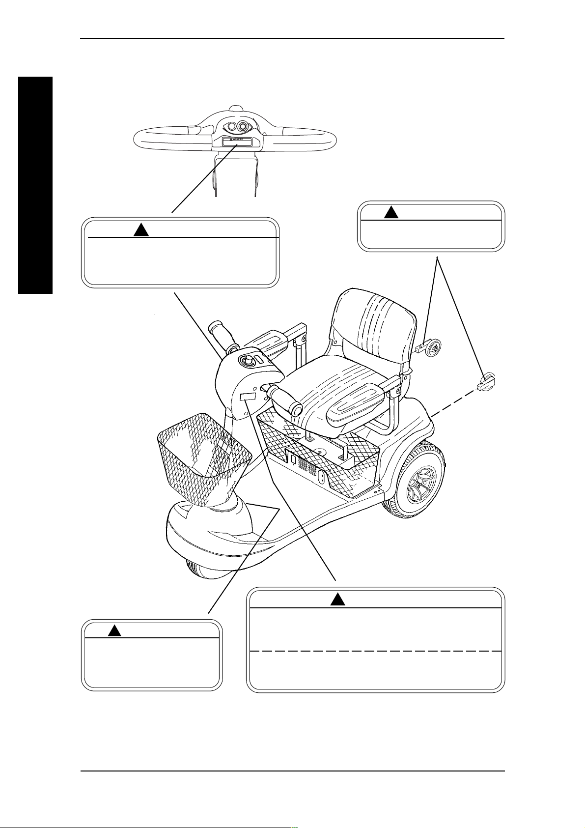
WARNING/CAUTION LABEL LOCATION
GENERAL GUIDELINES
Remove key from the ignition while scooter is
not in use. Otherwise, injury and/or damage to
the scooter or surrounding property may occur.
DELTA
TILLER
! WARNING
STANDARD
TILLER
1090105
NOTE: Not included on ZOOM-
3. ZOOM-3 is equipped with
non-removable anti-tip tubes.
WARNINGWARNING
!
WARNING
WARNINGWARNING
DO NOT operate without the
anti-tip tubes installed. 60106X144
WARNING WARNING
!
WARNING
WARNING WARNING
DO NOT operate the scooter unless the tiller is in the locked position.
CAUTIONCAUTION
!
CAUTION
CAUTIONCAUTION
DO NOT lift scooter up by the
front or rear shroud. Otherwise, damage to the scooter
may occur. 1089265
Invacare Scooters 14 Part No. 1090132 Rev F
DO NOT lean against or pull forward on the tiller while mounting
or dismounting the scooter. Otherwise, injury may occur.
The manufacturer disclaims all responsibility for any personal
injury or property damage which may occur as a result of
improper or unsafe use of its products. 1090104

SAFETY INSPECTION/MAINTENANCE
This Procedure Includes the Following:
Safety Inspection Checklist
Maintenance
Troubleshooting
NOTE: Every six (6) months take the scooter to a qualified technician for a thorough inspection and
servicing. Regular cleaning will reveal loose or worn parts and enhance the smooth operation of the
scooter. To operate properly and safely, the scooter must be cared for just like any other vehicle.
Routine maintenance will extend the life and efficiency of the scooter.
Initial adjustments should be made to suit your personal body structure and preference.
Thereafter follow these maintenance procedures:
ITEM INITIALLY INSPECT/ADJUST
WEEKLY MONTHLY PERIODICALLY
GENERAL
Scooter drives straight (no excessive
drag/pull to one side). X X
SAFETY INSPECTION/
MAINTENANCE
BRAKE*
Does not bind or interfere with travel. XX
Brake easy to disengage/engage. XX
UPHOLSTERY (PROCEDURES 5 AND 6)
Inspect for rips, tears. XX
REAR WHEELS (PROCEDURE 9)
No excessive side movement or binding when
raised and turned. XX
FRONT WHEELS (PROCEDURE 9)
Inspect wheel/fork assembly for proper tension
by spinning wheel, wheel should come to a
gradual stop. XX
Loosen/tighten locknut if wheel wobbles
noticeably or binds to a stop. XX
Wheel bearings are clean and free of moisture. XX
CAUTION: As with any vehicle, the
wheels and tires should be checked
periodically for cracks and wear and should
be replaced.
TILLER (PROCEDURE 8)
Ensure that tiller adjustment handle engages
and disengages properly and securely
(PROCEDURE 3). XX
Scooter stops completely when throttle is
released (Does not continue to roll as if
throttle is activated). X X
SEAT (PROCEDURE 5)
Inspect seat swivel for release and engagement. XX
Seat locks into the determined swivel positions. XX
*NOTE: This includes the hand brake on the PANTHER MX-4.
Part No. 1090132 Rev F 15 Invacare Scooters

ITEM INITIALLY INSPECT/ADJUST
TIRES (PROCEDURE 9)
Inspect for flat spots and wear. XX
If pneumatic tires check for proper inflation. XX
CAUTION: As with any vehicle, the
wheels and tires should be checked
periodically for cracks and wear, and should
be replaced.
CLEANING
Clean upholstery and armrests. X
Clean molded frame. X
MAINTENANCE
SAFETY INSPECTION/
FRONT AND REAR SHOCKS PANTHER MX-4 ONLY
Bolts are tight. XX
CLEANING X X
HEADLIGHTS (where applicable)
Inspect headlight bulbs for proper operation. XX
PROCEDURE 2SAFETY INSPECTION/MAINTENANCE
WEEKLY MONTHLY PERIODICALLY
MAINTENANCE
WARNING
After ANY adjustments, repair or service and BEFORE use, make sure
that all attaching hardware is tightened securely - otherwise, injury or
damage may occur.
CAUTION
DO NOT over-tighten hardware attaching to the frame. This could cause
damage to the frame.
SUGGESTED MAINTENANCE PROCEDURES
1. Before using the powered scooter, make sure all nuts and bolts are tight. Check any
parts for damage or wear and replace. Check all parts for proper adjustment.
2. Ensure that batteries are properly maintained and charged as required (PROCEDURE 4).
3. Inspect brake for proper operation (PROCEDURE 3).
4. The wheels and tires should be checked periodically for cracks and wear, and should
be replaced by a qualified technician.
5. Regularly check for loose nuts and/or bolts in the front and rear wheels. If loose,
have them adjusted by a qualified technician (PROCEDURE 9).
6. Clean dirt, dust and grease from exposed components.
7. Periodically have the bearings of the front wheel checked to make sure they are
clean and free from moisture.
Invacare Scooters 16 Part No. 1090132 Rev F
PROCEDURE 2SAFETY INSPECTION/MAINTENANCE
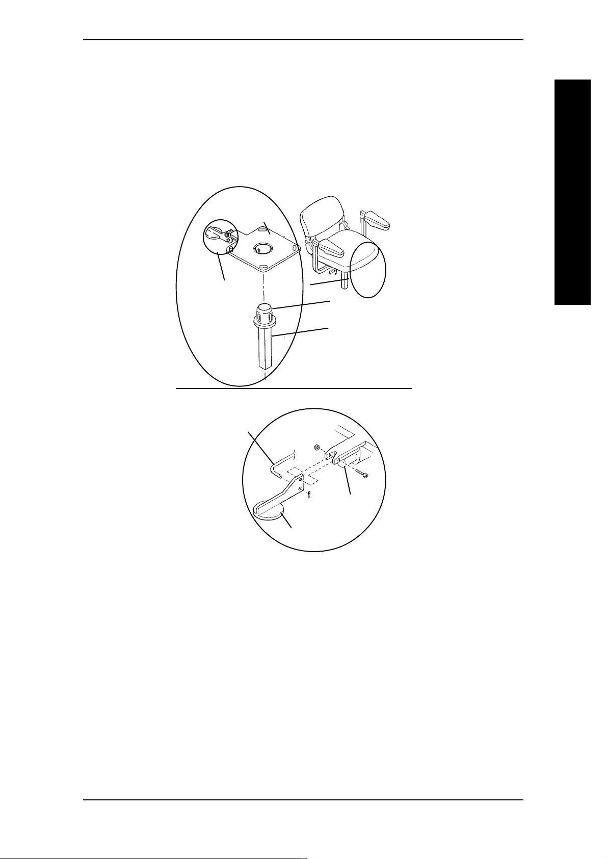
LUBRICATION POINTS (FIGURE 1)
1. Every six (6) months the following components should be lubricated. Use a Teflon
lubricant if necessary (FIGURE 1).
A. Seat Lever, Connecting Pin, and Release Pin.
B. Top of Seat Adaptor.
Seat
Plate
See
DETAIL
"A"
Top
®
SAFETY INSPECTION/
MAINTENANCE
Seat
Adaptor
DETAIL "A"
Connecting
Pin
Release
Pin
Seat Lever
FIGURE 1 - LUBRICATION POINTS
Note: Teflon - Registered trademark of E.I. Du
Pont Nemours and Company.
Part No. 1090132 Rev F 17 Invacare Scooters

SAFETY INSPECTION/MAINTENANCEPROCEDURE 2
TROUBLESHOOTING GUIDE
LIMITED DRIVING
DISTANCE.
BATTERIES NOT
CHARGING.
MAINTENANCE
SAFETY INSPECTION/
BATTERIES DRAW
EXCESSIVE CURRENT
WHEN CHARGING.
CHARGE INDICATOR
SHOWS LOW CHARGE
LEVEL IMMEDIATELY
AFTER CHARGING.
SYMPTOM
PROBABLE CAUSE
Batteries not charged long enough.
Batteries weak, won't hold charge.
Charger not working.
Battery Connections loose.
NO current at wall outlet.
BAD connection on Charger,
Charger Cable, Plug or Internal
Wiring problem.
Battery Failure.
Batteries weak, won't hold charge.
Charger not operating.
SOLUTION
Charge batteries overnight or
ensure 8 hours of charge between
use times (PROCEDURE 4).
Replace Batteries
(PROCEDURE 4).
Replace Charger.
Check all connections. Secure
connections (PROCEDURE 4).
Switch to another wall outlet.
Replace Charger or internal
repairs required. Contact Dealer
or Invacare.
Replace Batteries
(PROCEDURE 4).
Replace Batteries
(PROCEDURE 4).
Replace Charger.
BATTERY INDICATOR
FLASHES THE CHARGE
LEVEL IS LOW - TOO
SOON AFTER BEING
RECHARGED.
SCOOTER WILL NOT
DRIVE.
MOTOR CHATTERS
OR RUNS
IRREGULARLY.
Have charger checked.
Weak batteries.
Brake-Release Lever disengaged.
Batteries require charging.
Key not fully plugged in.
Charger plugged in.
Circuit breaker tripped.
Soft stop is engaged.If key is turned
"OFF" while driving, the scooter
artificially holds power for 1.5 seconds
slowly decelerating unit to a stop.
Fuse is Blown.
Electrical malfunction.
Service or replace charger.
Contact Dealer or Invacare.
Replace batteries (PROCEDURE
4).
Engage brake-release lever.
(procedure 3)
Charge batteries (PROCEDURE 4).
Ensure key is inserted fully into
power plug jack.
Unplug charger from scooter.
Reset breaker. If breaker trips
again, it may indicate need for
internal repairs. Contact Dealer
or Invacare.
With key in the "OFF" position,
wait 30 seconds and turn key to
"ON" position.
Replace Fuse (PROCEDURE 3).
Contact Dealer or Invacare.
Invacare Scooters 18 Part No. 1090132 Rev F

This Procedure Includes the Following:
Control Panel Features
Operation of the Scooter
Using the Hand Brake Lever/Brake Arm
PROCEDURE 3OPERATION
Brake Release Lever
Reset Circuit Breaker/Fuse Replacement
WARNING
After ANY adjustments, repair or service and BEFORE use, make sure
that all attaching hardware is tightened securely. Otherwise, injury or
damage may result.
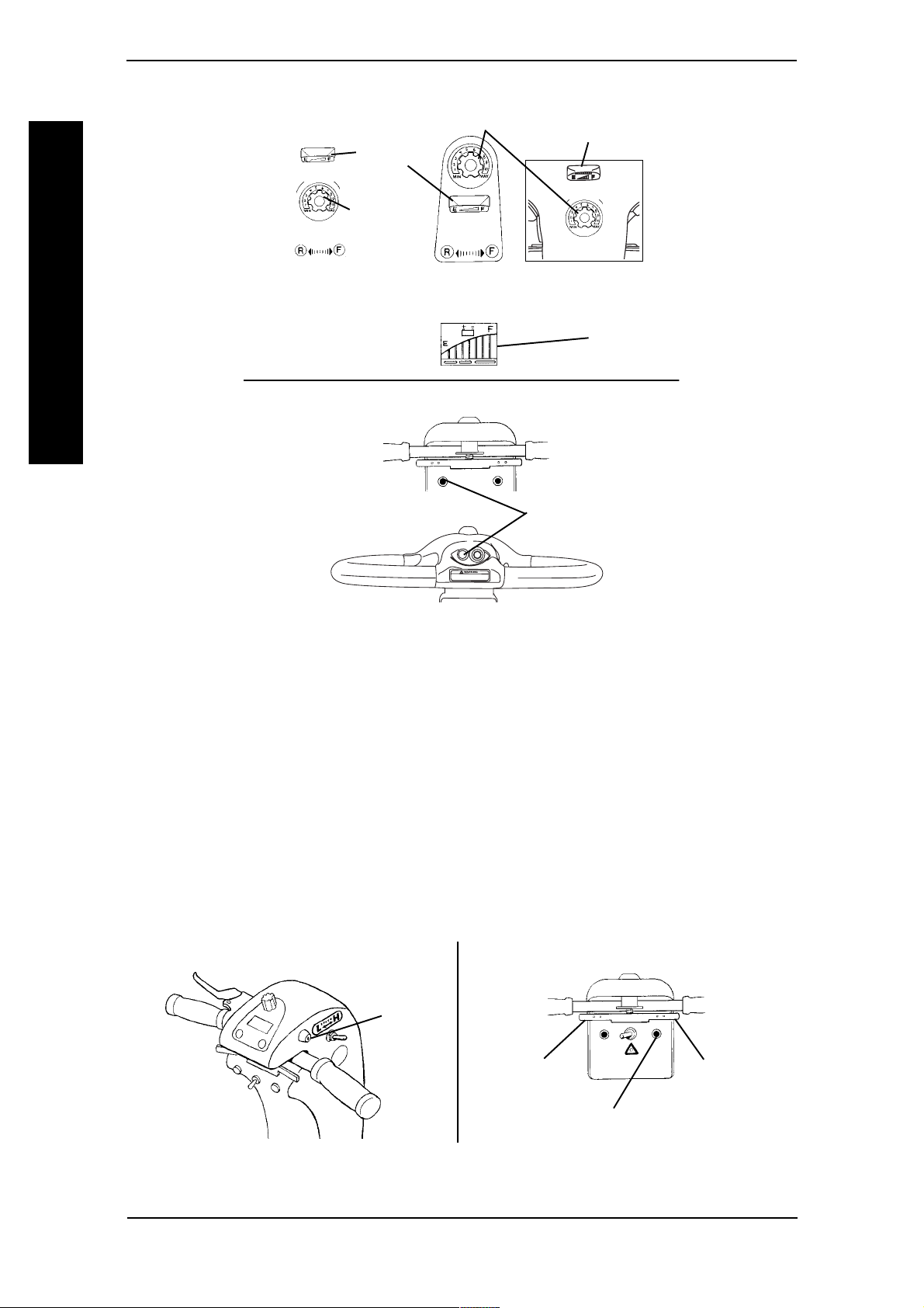
CONTROL PANEL FEATURES
ALL SCOOTER MODELS
With Delta or Standard Tillers (FIGURE 1).
1. Speed Control Knob - Located on the top face of the control panel. The number
one (1) represents the slowest speed and the number ten (10)
represents the fastest speed (DETAIL "A").
2. Battery Charge-Indicator - The charger indicator is located on the top face of
the control panel and has an "E" indicating EMPTY and an "F" indicating FULL.
NOTE: The battery charge indicator is composed of eight (8) bars which, when the power is
turned on, will illuminate showing the charge level of the batteries. The more number of bars
illuminated the more charge the batteries have. See chart below.
OPERATION
NUMBER OF CHARGE
BARS ILLUMINATED OF BATTERIES
8 fully charged
4 partially charged
0 discharged
NOTE: The number of bars illuminated may decrease when driving over uneven surfaces even
with batteries fully charged. True reading is with key inserted and
indicator illuminated with powered scooter stationary.
WARNING
When negotiating ramps, if the throttle control lever is released while in
FORWARD motion the powered scooter will "ROLLBACK" approximately one (1) foot before brake engages. If the throttle control lever is
released while in REVERSE motion the powered scooter will "ROLLBACK" approximately three (3) feet before brake engages.
3. Horn Button - Located on front face of control panel toward the left. (DETAIL "B").
Part No. 1090132 Rev F 19 Invacare Scooters
PROCEDURE 3 OPERATION
DETAIL "A"
Speed Control Knob
Battery
Charge
Indicator
Speed Control
Knob
Battery Charge
Indicator
OPERATION
ZOOM-3
TILLER
PANTHER MX-4 W/
STANDARD
TILLER
DELTA
TILLER
Battery Charge
STANDARD TILLER
DETAIL "B"
STANDARD
TILLER
DELTA
Horn Button
TILLER
FIGURE 1 - ALL SCOOTER MODELS WITH
DELTA OR STANDARD TILLERS
Indicator
With Standard Tillers (FIGURE 2).
1. Ignition - Located on right side of the tiller control panel (DETAIL "C").
2. Headlight Button - Located on the front face of the control panel on ALL models
EXCEPT LYNX SX-3 (DETAIL "D").
3. Throttle Control Lever - Located on the front face of the control panel. This
lever is the "gas pedal" (DETAIL "D").
DETAIL "C"
Ignition
Throttle
Control Lever
(REVERSE)
DETAIL "D"
Throttle
Control Lever
(FORWARD)
Headlight Button
FIGURE 2 - ALL SCOOTER MODELS WITH STANDARD TILLERS
Invacare Scooters 20 Part No. 1090132 Rev F

With Delta Tillers (FIGURE 3).
1. Ignition - Located on front face of the
tiller.
2. Headlight Button - Located on the
right side of the tiller.
PROCEDURE 3OPERATION
Head Light
Button
Ignition
3. Throttle Control Levers - Located
centralized to the handle grips of the
tiller.
PANTHER MX-4 SCOOTERS
Reverse/Forward
Throttle Control Lever
Throttle Control Lever
FIGURE 3 - ALL SCOOTER
MODELS WITH DELTA TILLERS
ONLY
With Standard Tillers (FIGURE 4)
1. Turn Signal Switch - Located on the front face of the control panel
(DETAIL "E").
2. Hazard Light Button - Located on
the front face of the control panel.
This button illuminates both turn signals.
NOTE: Switching from HIGH speed to LOW speed
decreases power (speed) by approximately 25%,
from 7¼ MPH to 5¼ MPH. Switching from LOW
speed to HIGH speed restores power (speed).
3. High/Low Speed Switch - This
switch is located on the right side of
the control panel (DETAIL "F").
DETAIL "E"
Turn Signal
Switch
DETAIL "F"
Hand Brake
Lever
Forward/Reverse
Hazard Light
Button
High/Low
Speed Switch
OPERATION
4. Hand Brake Lever - Located on left
hand grip (DETAIL "F").
With Delta Tillers (figure 5).
FIGURE 4 - PANTHER MX-4
SCOOTERS ONLY - WITH
1. Turn Signal Switch - Top face of
STANDARD TILLERS
controller.
2. Hazard Light Button - Right side of controller tiller.
NOTE: Switching from HIGH speed to LOW speed decreases power (speed) by approximately
25%, from 7¼ MPH to 5¼ MPH. Switching
from LOW speed to HIGH speed restores
power (speed).
3. High/Low Speed Switch - This
Turn Signal
Switch
High/Low
Speed Switch
Hazard Light
Button
switch is
located on the top face of the control
panel.
FIGURE 5 - PANTHER MX-4
SCOOTERS ONLY - WITH DELTA
TILLERS
Part No. 1090132 Rev F 21 Invacare Scooters

PROCEDURE 3 OPERATION
OPERATION OF THE SCOOTER (FIGURES 1-5)
Before attempting to sit in the powered scooter, REMOVE the key from
the ignition. This will ensure that the POWER is OFF and the scooter will
not drive.
To determine and establish your particular safety limits, practice bending,
reaching and transferring activities in several combinations in the presence of a qualified healthcare professional BEFORE attempting active use
of the powered scooter.
Ensure seat is properly locked before attempting transfer into or out of
OPERATION
the powered scooter. Attempting unsafe transfers may cause a fall from
the powered scooter resulting in bodily injury.
For individuals with balance problems, practice transferring activities
WITH AN ASSISTANT in the presence of a qualified healthcare
professional. DO NOT attempt to transfer into or out of the powered
scooter without assistance.
WARNING
1. Before operation of the powered scooter, review the CONTROL PANEL FEATURES
section in this procedure of the manual.
2. Install and charge batteries. Refer to REPLACING BATTERIES and CHARGING
THE BATTERIES in PROCEDURE 4 in this manual.
3. Transferring to and from the seat can be accomplished in one (1) of two (2) ways:
A. Flipping up the armrest makes entering/exiting easier.
B. For all models except ZOOM-3, the seat can be rotated in either direction.
Refer to 90º SEAT SWIVEL ADJUSTMENT in PROCEDURE 5 in this manual.
4. Once the seat is locked in the forward-facing position and both armrests are in the
DOWN position, adjust the tiller to a comfortable angle. Refer to TILLER ANGLE
ADJUSTMENT in PROCEDURE 8 in this manual.
5. Adjust speed control knob to the appropriate setting. For PANTHER MX-4 also
select low/ high speed.
NOTE: For driving indoors or on uneven terrain, a slower speed (and the selection of low speed
for PANTHER MX-4 is recommended. For soft terrain or steep inclines (no greater than 8º), a
faster speed may be necessary.
6. Insert the key into the ignition.
WARNING
Always depress the throttle control lever gradually. This will ensure
smooth safe starts.
NOTE: Throttle control levers are teetered such that moving one (1) will also move the opposite
side throttle control lever.
Invacare Scooters 22 Part No. 1090132 Rev F

PROCEDURE 3OPERATION
7. To operate the scooter, depress the throttle control lever in the following manner:
A. STANDARD TILLERS:
To move FORWARD - Push the RIGHT-SIDE of the throttle control lever.
To move in REVERSE- Push the LEFT-SIDE of the throttle control lever.
To STOP - Release the throttle control lever and the powered scooter will
quickly slow down and the brake will engage. PANTHER MX-4 - Use the hand
brake lever when needing
accelerated stops. See USING THE HAND BRAKE LEVER/BRAKE/BRAKE ARM
in this procedure of the manual.
B. DELTA TILLERS:
To move FORWARD - Pull the RIGHT-SIDE throttle control lever rearward
(toward user), or Push the LEFT-SIDE throttle control lever forward (away from user).
To move in REVERSE - Pull the LEFT-SIDE throttle control lever rearward (toward
user), or Push the RIGHT-SIDE throttle control lever forward away from user).
To STOP - Release the throttle control lever and the powered scooter will
quickly slow down and the brake will engage.
OPERATION
NOTE: To equip the scooter for left hand operation, contact a qualified technician.
The powered scooter is equipped with a "proportional" control meaning that the farther
you depress the throttle control lever, the faster the powered scooter will travel. With a
proportional control, you can drive as slowly in the high speed setting as you can in the
low speed setting. Your top speed, however, is limited by the setting of the speed-control
knob. For safety reasons, reverse speed is limited to approximately 50% of forward speed.
When first learning to drive, select a SLOW speed and try to drive the powered scooter AS
SLOWLY as possible by depressing the throttle control lever only slightly. This exercise will help you
learn to utilize the full potential of the proportional control and allow you to start and stop smoothly.
USING THE HAND BRAKE LEVER/BRAKE ARM (FIGURE 6)
NOTE: The hand brake lever and brake arm are only on the PANTHER MX-4 (Without Delta
Tiller).
CAUTION
ALWAYS release throttle control lever BEFORE using the hand brake. Using
the hand brake in conjunction with the throttle control lever will cause excessive wear on the brake and the stopping distance of the scooter will increase.
HAND BRAKE LEVER
1. Squeeze the hand brake lever when needing accelerated stops.
BRAKE ARM
1. The brake arm can only be used to stop the scooter when the brake-release lever is
manually disengaged. Refer to BRAKE-RELEASE LEVER in this procedure of the manual.
Part No. 1090132 Rev F 23 Invacare Scooters

PROCEDURE 3 OPERATION
BRAKE RELEASE LEVER
Ensure that the brake-release lever
is in the ON position (engaged)
before driving. There should be an
audible "click" when stopping and
starting.
BRAKE-RELEASE LEVER - Manually
engages and disengages the brake. The
OPERATION
location of the brake-release lever is between the rear shroud and the rear wheel. For all models except ZOOM-3 and PANTHER
MX-4, the brake-release lever is on left hand side. For ZOOM-3 and PANTHER MX-4
MODEL, the brake-release lever is on the right hand side.
ALL MODELS EXCEPT PANTHER MX-4 (FIGURE 7)
Normal driving position for the brake is the ON (lever DOWN) position. Activation of
the throttle control lever automatically
releases the brake so the powered
scooter can drive. Releasing the throttle
control lever automatically engages the
brake so the powered scooter will not roll
on its own.
Brake release lever OFF (lever UP) and
the key removed allows the powered
scooter to be pushed. The powered
scooter cannot be driven with the brake in
the OFF (lever UP) position.
PANTHER MX-4 ONLY
(FIGURE 8)
Normal driving position for the brake is the ON (lever UP) position. Activation of the
throttle control lever automatically releases the brake so the powered scooter can
drive. Releasing the throttle control lever
automatically engages the brake so the
powered scooter will not roll on its own.
CAUTION
TOP VIEW OF
TILLER SHROUD
REAR VIEW OF
SCOOTER
Brake Arm
FIGURE 6 - USING THE HAND
BRAKE LEVER/BRAKE ARM
Brake Release Lever
F
F
➠
➠
O
N
O
Rear of
Scooter
NOTE: Remove key and disengage brake
before manually pushing the scooter.
FIGURE 7 - BRAKE RELEASE LEVER
- ALL MODELS EXCEPT
PANTHER MX-4
Rear of Scooter
Brake release lever OFF (lever DOWN)
and the key removed allows the powered
scooter to be pushed. The powered
scooter cannot be driven with the brake in
the OFF (lever DOWN) position.
Brake Release Lever
FIGURE 8 - BRAKE RELEASE LEVER
- PANTHER MX-4 ONLY
Invacare Scooters 24 Part No. 1090132 Rev F

PROCEDURE 3OPERATION
RESET CIRCUIT BREAKER/FUSE REPLACEMENT (FIGURE 9)
CIRCUIT BREAKER
NOTE: Key must be removed from ignition before resetting circuit breaker.
1. To reset, press circuit breaker button located on rear shroud.
FUSE REPLACEMENT
1. Remove seat. Refer to REMOVING/INSTALLING THE SEAT in PROCEDURE 5 of
this manual.
2. Remove rear shroud. Refer to REMOVING/
INSTALLING REAR SHROUD in PROCEDURE 9 of this manual.
3. Flip top of fuse holder open.
4. Pull fuse out and install NEW fuse.
5. Reverse STEPS 1-3 to reassemble.
OPERATION
Circuit
Breaker
Rear
Shroud
Top
Fuse
Button
Fuse
Holder
FIGURE 9 - RESET CIRCUIT BREAKER/FUSE REPLACEMENT
Part No. 1090132 Rev F 25 Invacare Scooters

This Procedure Includes the Following:
Removing/Installing the Batteries with Cables
Replacing the Batteries
Charging the Batteries
After ANY adjustments, repair or service and BEFORE use, make sure that all
attaching hardware is tightened securely - otherwise, injury or damage may
result.
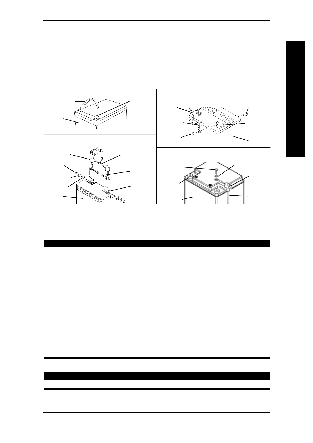
REMOVING/INSTALLING THE BATTERIES WITH CABLES
BATTERIES/CHARGING
(FIGURE 1)
NOTE: To install batteries, reverse the following procedure.
NOTE: When removing/installing batteries keep all foreign objects, especially metal, clear of battery terminals.
REMOVING
BATTERIES/CHARGINGPROCEDURE 4
WARNING
WARNING
Turn Power OFF and remove key from ignition.
Where applicable, ALWAYS use a battery lifting strap when moving a battery.
It is the most convenient method. It also helps to prolong the life of the battery.
DO NOT tip the batteries. Keep the batteries in an upright position.
The use of rubber gloves and chemical goggles is recommended when
working with batteries.
Top Battery
Fastening Strap
Rear
Sub-Frame
Battery
Lifting Strap
Retaining
Ring
Battery Wiring Harness
Red
Connector
Controller
Wiring
Harness
Black
Connector
Red Connector
Connector
Sub-Frame
Batteries
NOTE: Hardware is in included with batteries.
NOTE: Only Model LYNX SX-3 battery cable assemblies shown for clarity.
Black
Rear
FIGURE 1 - REMOVING/INSTALLING THE BATTERIES WITH CABLES
1. Turn Power OFF and remove key from ignition.
2. Remove the seat from the scooter. Refer to REMOVING/INSTALLING THE SEAT
in PROCEDURE 5 in this manual.
3. Remove the rear shroud. Refer to REMOVING/INSTALLING THE REAR SHROUD
in PROCEDURE 9 in this manual.
4. Disconnect top battery fastening strap and pull through retaining ring.
Invacare Scooters 26 Part No. 1090132 Rev F

BATTERIES/CHARGING PROCEDURE 4
5. Disconnect red and black connectors of the battery wiring harness from red and
black connectors of the controller wiring harness.
6. Remove batteries w/ cables from rear sub-frame.
REPLACING THE BATTERIES (FIGURE 2)
WARNING
Turn Power OFF and remove key from ignition.
Where applicable, ALWAYS use a battery lifting strap when moving a battery.
It is the most convenient method. It also helps to prolong the life of the battery.
DO NOT tip the batteries. Keep the batteries in an upright position.
The use of rubber gloves and chemical goggles is recommended when
working with batteries.
CAUTION
Place the powered scooter in a well ventilated area where work can be
performed without risking damage to carpeting or floor covering.
BATTERIES/CHARGING
NOTE: If there is battery acid on the sides of the battery, add baking soda to these areas to neutralize
the battery acid. Before reinstalling the NEW batteries, clean the baking soda from the batteries.
RECOMMENDED BATTERY TYPES
WARNING
The warranty and performance specifications contained in this manual
are based on the use of deep cycle gel cell or sealed lead acid batteries.
Invacare strongly recommends their use as the power source for this unit.
CAUTION
Failure to use the correct battery size and/or voltage may cause damage
to the powered scooter and give unsatisfactory performance.
NOTE: Both recommended battery types are spill proof and require no maintenance except
routine charging.
SCOOTER QTY VOLTS AMP
MODEL HOURS
ZOOM-3 2 12 12
LYNX SX-3 2 12 17
LYNX LX-3 2 12 31
LYNX LX-3
PANTHER LX-4 2 12 31
PANTHER MX-4 2 12 40
Plus
21231
NOTE: Charge batteries daily. It is critical not to let them run low at any time.
NOTE: Invacare recommends that both batteries be replaced if one (1) battery is defective.
Part No. 1090132 Rev F 27 Invacare Scooters

NEVER allow any of your tools and/or battery cables to contact BOTH
terminal(s) post(s) at the same time. An electrical short may occur and
injury or damage may occur.
The use of rubber gloves and chemical goggles is recommended when
working with batteries.
When tightening the clamps, always use a box or a crescent wrench.
Pliers will round off the nuts. NEVER wiggle the terminal when tightening. The battery may become damaged.
1. Remove the batteries with cable assemblies from scooter. Refer to REMOVING/
INSTALLING THE BATTERIES WITH CABLES in this procedure of the manual.
BATTERIES/CHARGING
2. If necessary, lift battery cable boot up off of the battery terminal.
3. For ZOOM-3 - remove the battery cable connections by gapsing the connectors
and pulling.
4. For all other models, remove the hardware that secures the cable assembly to the
battery terminals. Hardware for each model is as follows:
BATTERIES/CHARGINGPROCEDURE 4
WARNING
CAUTION
A. For LYNX SX-3 - Mounting screw, lockwasher, washers, and locknut.
B. For LYNX LX-3, LX-3
Plus
and PANTHER LX-4 - Mounting screw and locknut.
C. For PANTHER MX-4 - Mounting screw and lockwasher.
5. Repeat STEPS 2 - 4 for opposite battery.
6. Position battery cables onto NEW battery terminals.
CAUTION
The positive (+) terminal MUST be connected to the positive (+) terminal/post, otherwise serious damage will occur to the electrical system.
WARNING
Always make black cable to negative terminal connection first. Otherwise,
injury may result.
A. BLACK Cable to NEGATIVE (-) Terminal.
B. RED Cable to POSITIVE (+) Terminal.
7. Secure battery cable to the battery terminals:
A. For ZOOM-3 - Install battery cable connector onto battery terminal ensuring
terminal rests INSIDE connector.
B. For LYNX SX-3 - Use mounting screw, lockwasher, two (2) washers, and
locknut. Securely tighten.
C. For LYNX LX-3, LX-3
Plus
and PANTHER LX-4 - Use the mounting screw
and locknut. Securely tighten.
D. For PANTHER MX-4 - Use the mounting screw and lockwasher. Securely
tighten.
Invacare Scooters 28 Part No. 1090132 Rev F
BATTERIES/CHARGING PROCEDURE 4
8. Repeat STEP 7 for opposite battery.
9. Verify that all connections are correct and terminals are secure.
10. Install the NEW battery with cable assemblies onto the scooter. Refer to REMOVING/INSTALLING THE BATTERIES W/ CABLES in this procedure of the manual.
11. Charge the batteries. Refer to CHARGING THE BATTERIES in this procedure of the manual.
BATTERIES/CHARGING
Battery Cable
Connector
Battery
Battery Cable
Boot
Locknut
Lockwasher
Washer
Battery
MODEL ZOOM-3
Battery
Terminal
MODEL LYNX SX-3
Battery Cable
Mounting
Screw
Battery
Terminal
MODELS LYNX LX-3, LX-3
Battery
Cable
Cable Boot
Locknut
Mounting
Battery
Terminal
FIGURE 2 - REPLACING THE BATTERIES
CLEANING BATTERY TERMINALS
PANTHER LX-4
Battery
MODEL PANTHER MX-4
Screw
Battery
Plus
AND
Mounting Screw
Battery
Terminal
Battery
Lockwasher
Battery
Cable
Boot
Battery
Cable
WARNING
DO NOT allow conductive material such as a wrench to join the two (2) battery
terminals. This will result in a dead short that can cause burns to you and damage to the battery.
Most batteries are not sold with instructions. However, warnings are frequently noted on the top of the batteries. Read them carefully.
DO NOT allow the liquid in the battery to come in contact with skin, clothes or
other possessions. It is a form of acid and harmful or damaging burns may result.
Should the liquid touch your skin, wash the area immediately and thoroughly with
cool water. In serious cases or if eye contact is made, seek medical attention IMMEDIATELY.
The use of rubber gloves and chemical goggles is recommended when working
with batteries.
NEVER smoke or strike a match near batteries.
1. Examine battery clamps/terminals for corrosion.
WARNING
If there are any cracks or leaks replace batteries IMMEDIATELY.
2. Clean the terminals and inside the battery clamps by using a battery cleaning tool,
wire brush, or medium grade sand paper.
Part No. 1090132 Rev F 29 Invacare Scooters

BATTERIES/CHARGINGPROCEDURE 4
NOTE: Upon completion, these areas should be shiny, not dull.
3. Carefully dust off all metal particles.
CHARGING THE BATTERIES
WARNING
Never attempt to recharge the batteries by attaching cables directly to
the battery terminals or clamps.
DO NOT attempt to recharge the batteries and operate the powered
scooter at the same time.
CAUTION
New batteries MUST be fully charged prior to initial use of the powered
scooter.
BATTERIES/CHARGING
Always charge new batteries before initial use or battery life will be reduced.
As a general rule, you should recharge your batteries as frequently as possible to assure the longest possible life and to minimize required charging
time. Plan to recharge them when you do not anticipate using the powered
scooter.
The range per battery charge using recommended batteries should be approximately 5 to 9
hours of typical operation. Extensive use on inclines may substantially reduce per charge mileage.
NEVER leave the charger unattended when the circuit breaker (charger)
is tripping ON and OFF.
NOTE: If performing charging procedures independently, READ and CAREFULLY follow the
individual instructions for each charger (supplied or purchased).
NOTE: If charging instructions are not supplied, consult a qualified service technician for proper
procedures.
MODEL BATTERY CHARGER* POWER CORD
ZOOM-3 Remote (Supplied) Supplied
LYNX SX-3 On-Board Supplied
LYNX LX-3 On-Board Supplied
LYNX LX-3
PANTHER LX-4 Remote (Supplied) Supplied
PANTHER MX-4 On-Board Supplied
Plus
WARNING
On-Board Supplied
* NOTE : AC power cord (3-prong plug, 15 ampere current
rating; industrial type)
Invacare Scooters 30 Part No. 1090132 Rev F
BATTERIES/CHARGING PROCEDURE 4
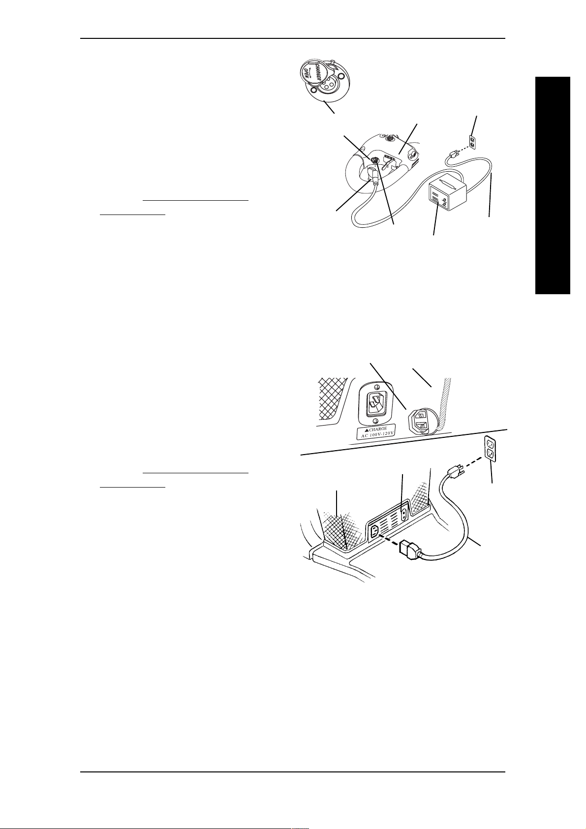
REMOTE BATTERY
CHARGER (FIGURE 3)
NOTE: Charger Port Covers pivot
LEFT and RIGHT to OPEN
1. Open the charger port cover located
on the left side of the tiller.
2. Plug charger connector into charger
Charger Port
Cover
port.
3. Plug charger into standard 110-volt
wall outlet.
4. Refer to BATTERY CHARGER
OPERATION in this procedure of the
manual.
Charger
Connector
Charger
FIGURE 3 - CHARGING THE
BATTERIES
(REMOTE BATTERY CHARGER)
ON-BOARD BATTERY CHARGER (FIGURE 4)
Port
Tiller
Charger
110-Volt
Wall Outlet
AC Power
Cord
BATTERIES/CHARGING
1. Remove charger port cover, where
applicable.
2. Plug AC power cord into on-board
battery charger located underneath
floor basket.
3. Plug AC power cord into 110-volt wall
outlet.
4. Refer to BATTERY CHARGER
OPERATION in this procedure of the
manual.
Charger Port
Cover
Floor Basket
NOTE: On Board Chargers built after 10/00 have
a cover attached with a chain to the Floor basket
Chain
On-Board Battery
Charger
110-Volt
Wall
Outlet
AC Power
Cord
FIGURE 4 - CHARGING THE
BATTERIES
(ON-BOARD BATTERY CHARGER)
Part No. 1090132 Rev F 31 Invacare Scooters

BATTERIES/CHARGING PROCEDURE 4
BATTERY CHARGER OPERATION (FIGURE 5)
1. The ON/OFF LED indicator will illuminate Solid Red indicating that the charger is ON.
2. If the ON/OFF LED indicator is "Blinking" Red, this is abnormal. Perform one (1) of
the following:
A. Remote Battery Chargers - Unplug battery charger from charger port and
wall outlet. Contact Invacare at the number listed on the back page.
B. On-board Battery Chargers - Unplug AC power cord from the on-board
battery charger and wall outlet. Contact Invacare at the number listed on the back
page.
3. When the ON/OFF LED indicator is OFF, charger is OFF.
4. When the CHARGE LED indicator is "Blinking" Green, the batteries are charging.
BATTERIES/CHARGING
5. When the CHARGE LED indicator is Solid Green, the batteries are FULLY charged (or as fully
charged as their condition will allow). At this point, the charger automatically stops charging.
6. If the charger is on and the CHARGE LED indicator is OFF, the charger is disconnected. Check that all connections are secure. If CHARGE LED indicator is still
OFF, perform one (1) of the following:
A. Remote Battery Chargers - Unplug battery charger from charger port and
wall outlet. Contact Invacare at the number listed on the back page.
B. For On-board battery chargers - Unplug AC power cord from the on-board
battery charger and wall outlet. Contact Invacare at the number listed on the back
page.
NOTE: The powered scooter is designed with an an electrical lockout to prevent it from being
driven while the charger is plugged in to an outlet.
ON/OFF INDICATOR STATUS
SOLID RED CHARGER ON
"BLINKING" RED ABNORMAL
LED "OFF" CHARGER OFF
CHARGING INDICATOR STATUS
"BLINKING" GREEN CHARGING
SOLID GREEN FULLY CHARGED
LED "OFF" CHARGER
ON-BOARD BATTERY CHARGER
ON/OFF Indicator Light
Charging
Indicator
Light
REMOTE BATTERY CHARGER
ON/OFF
Indicator
Light
Charging
Indicator
Light
FIGURE 5 - BATTERY CHARGER
OPERATION
(REMOTE AND ON-BOARD
BATTERY
Invacare Scooters 32 Part No. 1090132 Rev F

This Procedure Includes the Following:
Removing/Installing the Seat
Adjusting the Seat Height
90º Seat Swivel Adjustment
Adjusting the Seat Depth
PROCEDURE 5SEAT
Using the Adjustable Seat Slide
Removing/Installing Seat Upholstery/Cushion
WARNING
After ANY adjustments, repair or service and BEFORE use, make sure
that all attaching hardware is tightened securely - otherwise, injury or
damage may result.
REMOVING/INSTALLING THE SEAT
DETERMINING SEAT POST TYPE (FIGURE 1)
1. Visually inspect the seat post to determine if you have a SOLID or ADJUSTABLE seat post.
SEAT
SOLID
SEAT POST
ADJUSTABLE SEAT POST
ZOOM-3
FIGURE 1 - DETERMINING SEAT
POST TYPE
Part No. 1090132 Rev F 33 Invacare Scooters

PROCEDURE 5 SEAT
REMOVING (FIGURE 2)
1. Remove the stability knob located under the seat on the frame post.
CAUTION
When the seat height adjustment pin is removed, the weight of the seat
assembly MUST be supported to prevent the seat from falling onto the
frame.
2. Perform one of the following:
SEAT
A. For solid seat post and
adjustable seat post ZOOM-3 -
proceed to STEP 3.
B. For adjustable height seat post
- remove the seat height adjustment pin from seat post and retain
for installation.
3. Lift seat assembly up and remove from
frame post.
INSTALLING (FIGURE 2)
WARNING
Ensure that seat is locked into the
forward position BEFORE and
DURING operation of the scooter.
Otherwise, injury to the user and/
or damage to the scooter may
result.
1. Position seat post of seat assembly into
frame post with seat in FORWARD
position.
Stability
Knob
Frame
Post
Seat
Post
NOTE: Only the Contour Seat shown for
clarity. The Deluxe Seat removes/installs in
the same manner.
Seat Height
Adjustable
Height Seat
Post
Bend End of Pin Lock
AWAY From Pin
Adjustment Pin
Pin Lock
FIGURE 2 - REMOVING/
INSTALLING THE SEAT
Seat
NOTE: For adjustable height seat posts ensure that the adjustment holes align with the holes
on the SIDES of the frame post.
2. If necessary, rotate seat to the forward position. Refer to 90º SEAT SWIVEL ADJUSTMENT
in this procedure of the manual.
WARNING
Ensure that the seat height adjustment pin is properly engaged and locked.
Otherwise, injury and/or damage may result.
DO NOT use the stability knob to adjust the seat height. It is NOT designed
to support the weight of the user. Otherwise, injury to the user and/or damage to the scooter may result.
3. Perform one of the following:
A. For solid seat post - lower seat assembly down until seat post rests on mount-
ing screw installed inside frame post.
B. For adjustable height seat post - lower seat assembly down to desired height
and install seat height adjustment pin through frame post and seat post and secure.
Refer to ADJUSTING THE SEAT HEIGHT in this procedure of the manual.
Invacare Scooters 34 Part No. 1090132 Rev F

PROCEDURE 5SEAT
NOTE: When installing the seat height adjustment pin, it is necessary to support the weight of
the seat assembly.
C. For adjustable seat seat post ZOOM-3 - install seat assembly onto seat post
with the seat in the forward position.
4. Reinstall stability knob. Hand tighten.
ADJUSTING THE SEAT HEIGHT
1. Determine seat post type. Refer to DETERMINING SEAT POST TYPE in this procedure
of the manual.
2. Perform one (1) of the following:
A. For solid seat posts proceed to SOILD SEAT POSTS in this procedure of the
manual.
B. For adjustable height seat posts proceed to ADJUSTABLE SEAT POSTS in
this procedure of the manual.
WARNING
DO NOT use the stability knob to adjust the seat height. It is NOT designed
to support weight of the user. Otherwise, injury to the user and/or damage
to the scooter may result.
SEAT
SOLID SEAT POST (FIGURE 3)
1. Remove the seat. Refer to REMOVING/INSTALLING THE SEAT in this procedure
of the manual.
2. Remove the rear shroud. Refer to REMOVING/INSTALLING THE REAR SHROUD
in PROCEDURE 9 of this manual.
3. Remove the batteries w/ cables. Refer to REMOVING/INSTALLING THE
BATTERIES WITH CABLES in PROCEDURE 4 of this manual.
4. If necessary, remove the floor basket. Refer to REMOVING/INSTALLING THE
FLOOR BASKET in PROCEDURE 11 of this manual.
5. Remove the mounting screw and locknut from the frame post.
6. Perform one (1) of the following:
A. For LYNX SX-3, and PAN-
THER MX-4 - Insert mounting
screw into one (3) of the three (3)
height adjustment holes located on
the frame post.
B. For LYNX LX-3, For LYNX
LX-3
Plus
and PANTHER LX-4 Insert mounting screw into one (1)
of the four (4) height adjustment
holes located on the frame post.
Stability
Knob
Locknut
Frame Post
Mounting
Screw
Height
Adjustment
Holes
Front Frame
Assembly
7. Secure mounting screw in place with
EXISTING locknut. Securely tighten.
8. Reassemble scooter by reversing
STEPS 1-4.
NOTE: Tiller assembly, rear frame assembly,
and front wheel are not shown for clarity.
FIGURE 3 - ADJUSTING THE SEAT
HEIGHT - SOLID SEAT POSTS
Part No. 1090132 Rev F 35 Invacare Scooters

SEAT
PROCEDURE 5 SEAT
ADJUSTABLE HEIGHT SEAT POST (FIGURE 4)
WARNING
Ensure that the seat height adjustment pin is properly engaged and
locked. Otherwise, injury and/or damage may result.
DO NOT use the stability knob to adjust the seat height. It is NOT designed to
support the weight of the user. Otherwise, injury to the user and/or damage to
the scooter may result.
zoom-3
1. Remove the seat. Refer to REMOVING/INSTALLING THE SEAT in this procedure of the
manual.
2. Remove the stability knob located on the front of the frame post.
3. Remove the rear shroud. Refer to REMOVING/INSTALLING THE REAR SHROUD
in PROCEDURE 9 of this manual.
4. Disengage and remove the seat height adjustment pin from the seat post.
5. Adjust the seat post to the desired height adjustment.
6. Reinstall the seat height adjustment pin through the frame post and seat post.
7. Secure the seat height adjustment pin by performing the following steps:
A. Swivel the pin lock until it is parallel to the pin .
B. Bend the end of the pin lock and position it over the end of the pin (DETAIL "A").
8. Reassemble scooter by reversing STEPS 1-3.
ALL other models
1. Remove the stability knob located on
the front of the frame post.
CAUTION
When the seat height adjustment pin
Adjustable
Height Seat
Post
Adjust-
ment Pin
is removed, the weight of the seat
assembly MUST be supported to
prevent the seat from falling onto
Frame
Post
Pin Lock
the frame.
DETAIL "A"
2. Disengage and remove the seat height
adjustment pin from the seat post.
3. Adjust the seat assembly into the
Bend End of
Pin Lock AWAY
From Pin
frame post to the desired height
adjustment.
4. While holding the seat assembly in
place, install the seat height adjustment
FIGURE 4 - ADJUSTING THE SEAT
HEIGHT - ADJUSTABLE HEIGHT
SEAT POSTS
pin through the frame post and seat post.
Seat
Height
5. Secure the seat height adjustment pin by performing the following steps:
A. Swivel the pin lock until it is parallel to the pin .
B. Bend the end of the pin lock and position it over the end of the pin (DETAIL "A").
Invacare Scooters 36 Part No. 1090132 Rev F

PROCEDURE 5SEAT
90º SEAT SWIVEL ADJUSTMENT
ALL MODELS EXCEPT ZOOM-3 (FIGURE 5)
WARNING
Ensure that seat is locked into the forward position BEFORE and DURING operation of the scooter. Otherwise, injury to the user and/or damage to the scooter may result.
CAUTION
PANTHER MX-4 ONLY - DO NOT use the seat swivel option when the
following combination occurs. Accessories are installed (such as Safety
Flag, Crutch/Cane Holder, etc.) and the seat is mounted in lowest height
adjustment position. Otherwise, damage to the scooter may occur.
1. The swivel release lever is located just
beneath the seat on the right side.
2. Pull the swivel release lever UP to
rotate the seat.
Seat
Seat
SEAT
NOTE: The seat locks in position at 90º
intervals. The seat is locked when an audible
click is heard.
NOTE: Seat swivels
360º in either direction.
Swivel Release Lever
(Lift UP to activate)
3. Rotate the seat to the desired position.
NOTE: Only the Contour Seat shown for clarity.
The Deluxe Seat swivels in the same manner.
FIGURE 5 - 90º SEAT SWIVEL
ADJUSTMENT
ADJUSTING THE SEAT DEPTH
ALL MODELS EXCEPT ZOOM-3 (FIGURE 6)
NOTE: This procedure applies to the Contour Seat ONLY. To adjust the seat depth on the
Deluxe Seat, refer to ADJUSTABLE SEAT SLIDE in this procedure of the manual.
1. Remove the seat. Refer to REMOVING/INSTALLING THE SEAT in this procedure of
the manual.
2. Remove the seat upholstery and cushion insert. Refer to REMOVING/INSTALLING
THE SEAT UPHOLSTERY in this procedure of the manual.
3. Place seat assembly upside down on ground/floor.
4. Remove the four (4) mounting screws, washers, and lockwashers that secure the
swivel seat assembly and seat stand to the seat.
NOTE: When aligning the swivel seat assembly with the seat stand, the swivel lever must be
positioned on either side so that the lever sits in the cutout provided on the seat stand.
5. Align the following three (3) items:
A. The slots on the swivel seat assembly.
B. The slots on the seat stand.
C. One (1) of the two (2) mounting positions on the underside of the seat.
Part No. 1090132 Rev F 37 Invacare Scooters

PROCEDURE 5 SEAT
SEAT
6. Secure all three (3) components
together with the four (4) EXISTING
mounting screws, lockwashers, and
washers in the following manner:
WARNING
The two (2) longer mounting screws
MUST be used to secure the rear of
the seat assembly together and the
two (2) shorter mounting screws
MUST be used to secure the front of
the seat assembly together. Otherwise, damage to the seat and/or
injury to the user may result.
A. Use the shorter mounting screws
to secure the front of the seat
assembly together. Securely
tighten.
B. Use the longer mounting screws to
secure the rear of the seat assembly together. Securely tighten.
Mounting
Positions
Seat
Seat
Cutout
Slot
Swivel
Lever
Washer
Lockwasher
Shorter
Mounting
Screws
Longer Mounting Screw
(NOTE: Only one (1) shown for clarity)
Stand
Cutout
Slot
Seat
Swivel
Assembly
FIGURE 6 -ADJUSTING THE SEAT
DEPTH
7. Install the seat upholstery and cushion insert onto the seat. Refer to REMOVING/
INSTALLING THE SEAT UPHOLSTERY in this procedure of the manual.
8. Install the seat. Refer to REMOVING/INSTALLING THE SEAT in this procedure of
the manual.
USING THE ADJUSTABLE SEAT SLIDE (FIGURE 7)
NOTE: This option is only available on the Deluxe Seat, models PANTHER LX-4 and PANTHER
MX-4.
1. Lift up on the release lever.
2. Slide seat forward/backward to the
desired position.
3. Release lever to lock seat in position.
FIGURE 7 - USING THE
ADJUSTABLE SEAT SLIDE
Release
Lever
Seat
Invacare Scooters 38 Part No. 1090132 Rev F

PROCEDURE 5SEAT
REMOVING/INSTALLING THE SEAT UPHOLSTERY/
CUSHION (FIGURE 8)
NOTE: This procedure applies to the Contour
Seat Only. Seat upholstery on the Deluxe seat
CANNOT be removed.
Seat
Upholstery
REMOVING
1. Unbutton the snap buttons of the seat
upholstery located on the rear of the
seat.
2. Remove seat upholstery and seat
cushion from seat.
INSTALLING
1. Install NEW/EXISTING seat cushion
onto seat.
2. Install NEW/EXISTING seat upholstery
onto seat.
3. Secure seat upholstery to seat with
rear snap buttons.
WARNING
Laundering or moisture will reduce flame retardation of the upholstery.
Seat Cushion
Seat
Upholstery
FIGURE 8 - REMOVING/
INSTALLING THE SEAT
UPHOLSTERY/CUSHION
Seat
SEAT
Snap
Buttons
Part No. 1090132 Rev F 39 Invacare Scooters

BACK
BACKPROCEDURE 6
This Procedure Includes the Following:
Folding/Unfolding the Back
Removing/Installing the Back Cushion/Upholstery
Adjusting the Back Recline
Adjusting the Headrest
WARNING
After ANY adjustments, repair or service and BEFORE use, make sure
that all attaching hardware is tightened securely - otherwise injury or
damage may result.
FOLDING/UNFOLDING THE
Seat
Back
BACK (FIGURE 1)
1. To fold, push back down towards seat.
2. To unfold, pull back up into the upright
position.
FIGURE 1 - FOLDING/UNFOLDING
THE BACK
REMOVING/INSTALLING
BACK CUSHION/UPHOLSTERY (FIGURE 2)
1. Unbutton the snap buttons on the back upholstery.
2. Remove and replace foam insert and/or upholstery.
3. Secure back upholstery to back with snap buttons.
NOTE: Clean upholstery with warm DAMP cloth and mild detergent to remove superficial soil.
WARNING
Laundering or moisture will reduce flame retardation of the upholstery.
Back Cushion
w/Foam Insert
Back
Snap
Buttons
FIGURE 2 - REMOVING/INSTALLING BACK CUSHION/UPHOLSTERY
Invacare Scooters 40 Part No. 1090132 Rev F

BACK PROCEDURE 6
ADJUSTING THE BACK RECLINE
ALL MODELS EXCEPT ZOOM-3, SX-3 AND LX-3 (FIGURE 3)
1. Loosen the outside jam nut.
2. Adjust mounting screw up or down to obtain the desired back angle.
3. Thread inside jam nut upwards to the top edge of the back bracket.
4. Securely tighten both the inside and
outside jam nuts to secure mounting
screw in place.
Mounting
Screw
WARNING
Both mounting screws MUST be
adjusted to obtain the same back
angle so the weight of the user is
evenly distributed. Otherwise,
injury to the user and/or damage to
the scooter may occur.
Outside
Jam Nut
Top Edge of Back
Bracket
Inside Jam Nut
FIGURE 3 - ADJUSTING THE BACK
RECLINE
5. Repeat STEPS 1-4 for opposite side of
back. To maintain same angle, count
the number of exposed threads between the mounting screw and the outside jam
nut.
ADJUSTING THE HEADREST
ALL MODELS EXCEPT ZOOM-3 (FIGURE 4)
1. To raise headrest, lift headrest up to desired position.
BACK
Back
Bracket
NOTE: Headrest is locked in position when an audible "click" is heard.
2. To lower headrest, push release tab towards the inside of the chair. Lower headrest
to desired position.
Headrest
Release
Tab
Headrest
Tube
FIGURE 4 - ADJUSTING THE HEADREST
Part No. 1090132 Rev F 41 Invacare Scooters
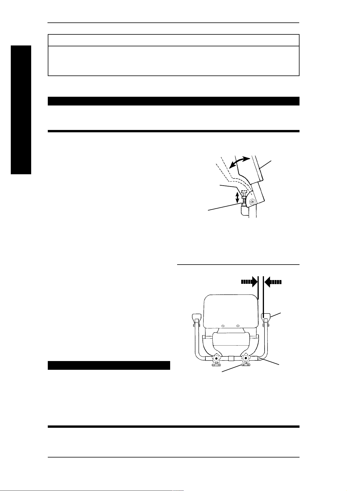
BACK
ARMSPROCEDURE 7
This Procedure Includes the Following:
Armrest Angle Adjustment
Armrest Width Adjustment
Armrest Depth/Height Adjustment
WARNING
After ANY adjustments, repair or service and BEFORE use, make sure that all
attaching hardware is tightened securely - otherwise, injury or damage may
result.
ARMREST ANGLE ADJUSTMENT
ALL SEATS BUILT AFTER 10/
00 AND CONTOUR
SEATS BUILT BEFORE 10/00
(FIGURE 1)
1. Lift the armrest up.
2. Loosen adjustment locknut.
3. Adjust mounting screw up or down to
the desired arm angle position.
4. Retighten adjustment locknut.
5. To determine the same angle for the
opposite armrest, count the exposed
threads on the socket screw.
6. Repeat STEPS 1-5 for opposite armrest.
ARMREST WIDTH
ADJUSTMENT
ALL MODELS EXCEPT ZOOM-3
(FIGURE 2)
1. Loosen the adjustment knob located
either beneath the seat frame or on
the back of the seat frame.
Armrest
Mounting
Screw
Adjustment
Locknut
FIGURE 1 - ARMREST ANGLE
ADJUSTMENT - ALL SEATS BUILT
AFTER 10/00 AND CONTOUR
SEATS BUILT BEFORE 10/00
MEASURE THIS
DISTANCE
Armrest
2. Adjust armrest in or out to the desired
position.
CAUTION
The armrest can be adjusted to a
Adjustment Knob
Seat
Frame
maximum distance of 4-1/2 inches
between the inside of the armrest
and the mounting shaft the armrest
is inserted into. If the armrest is
adjusted beyond the maximum 4-1/
NOTE: Only Contour Seat shown for clarity.
Width adjusts in the same manner for Deluxe
Seat.
FIGURE 2 - ARMREST WIDTH
ADJUSTMENT
2 inches, it will fall out.
3. Retighten adjustment knob securely.
4. Measure distance between back and inside of armrest.
5. Repeat STEPS 1-4 for opposite armrest setting armrest at distance determined in
Invacare Scooters 42 Part No. 1090132 Rev F
STEP 4.
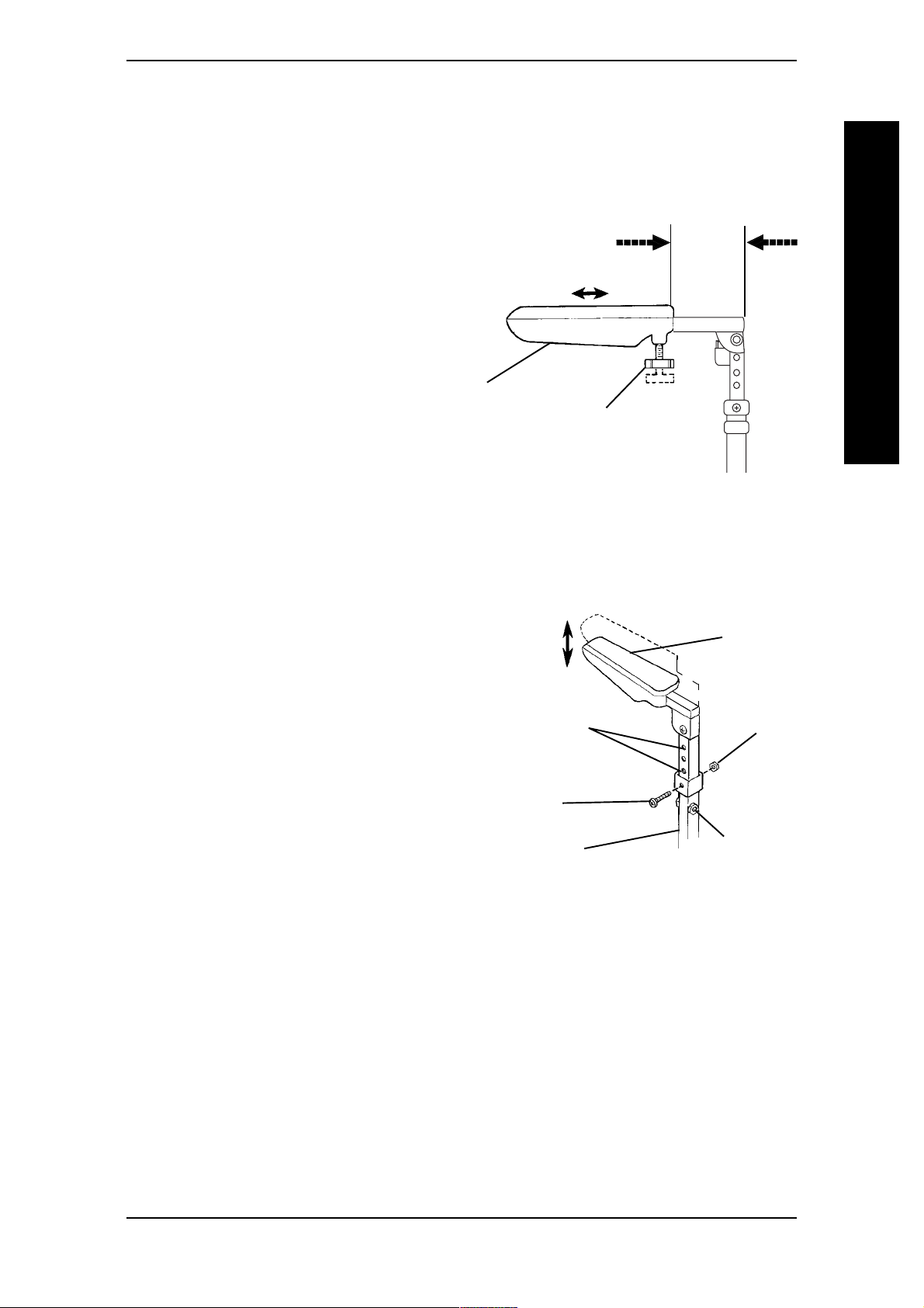
ARMREST DEPTH/HEIGHT ADJUSTMENT
ALL MODELS EXCEPT ZOOM-3 (FIGURE 3)
NOTE: These options are NOT available on
the CONTOUR SEATS Built BEFORE 10/00.
DEPTH
1. Loosen bottom adjustment knob.
2. Adjust armrest to desired position.
3. Retighten bottom adjustment knob
securely.
4. Measure distance from the back edge
of armrest to the back edge of the
armrest post.
MEASURE THIS
DISTANCE
Armrest
Bottom
Adjustment Knob
ARMSPROCEDURE 7
BACK
5. Repeat STEPS 1-4 for opposite armrest
setting armrest at distance determined
FIGURE 3 - ARMREST DEPTH
in STEP 4.
HEIGHT (FIGURE 4)
1. Loosen the stability set screws on of the armrest post.
2. Remove the mounting screw and
locknut that secure the armrest in
place.
3. Adjust armrest to desired mounting
position and secure with EXISTING
mounting screw and locknut. Securely
tighten.
4. Retighten the stability set screws on
the armrest post.
5. Count the number of exposed mounting holes above the armrest armpost.
6. Repeat STEPS 1-4 for opposite armrest
setting armrest at the mounting hole
determined in STEP 5.
COUNT
THESE
HOLES
(STEP 5)
Mounting
Screw
Armpost
FIGURE 4 - ARMREST HEIGHT
ADJUSTMENT
Armrest
Locknut
Stability
Set Screws
ADJUSTMENT
Part No. 1090132 Rev F 43 Invacare Scooters

PROCEDURE 8 TILLER ADJUSTMENT
This Procedure Includes the Following:
Tiller Angle Adjustment
WARNING
After ANY adjustments, repair or service and BEFORE use, make sure that all
attaching hardware is tightened securely - otherwise, injury or damage may
result.
TILLER ANGLE ADJUSTMENT
WARNING
Ensure that tiller is properly adjusted before driving the scooter.
TILLER ADJUSTMENT
After making ANY tiller angle adjustments and BEFORE use, the tiller MUST
be securely locked into position. Otherwise, a fall from the scooter could occur
causing bodily injury and/or damage to the scooter. Gently, push/pull against
tiller to ensure that the tiller is securely engaged into the adjustment plate.
FOLD DOWN TILLER ZOOM-3 (FIGURE 1)
NOTE: The ZOOM-3 features a fold down tiller. This allows you to fold down the tiller for transport and storage.
1. Adjust the seat to a comfortable position. Refer to ADJUSTING THE SEAT HEIGHT
in PROCEDURE 5 of this manual.
2. Backoff the tiller adjustment knob until the tiller bracket clears the tiller adjustment plate.
3. Pull tiller toward the front ot the scooter until the tiller adjustment plate is closed.
NOTE: When securing tiller in upright position, keep wiring clear of tiller adjustment plate.
4. Support the tiller with your right-hand.
5. Secure the tiller by hand tightening the adjustment knob, ensuring that the tiller
bracket secures the adjustment plate.
6. Gently, push/pull against tiller to ensure that the tiller is securely engaged into the locking
mechanism.
7. To fold the tiller for transport or storage reverse STEPS 2 - 5.
Tiller
Tiller
Tiller
Adjustment
Plate
Adjustment
Knob
Spacer
Tiller
Bracket
FIGURE 1 - FOLD DOWN TILLER - ZOOM-3
Invacare Scooters 44 Part No. 1090132 Rev F
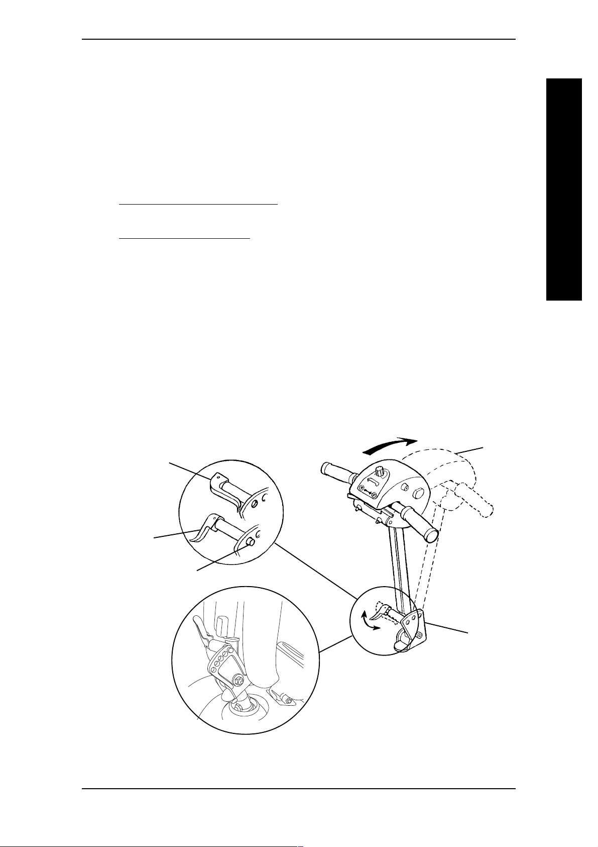
PROCEDURE 8TILLER ADJUSTMENT
ALL OTHER MODELS (FIGURE 2)
NOTE: The Powered Scooters features an adjustable tiller. This allows you to lock the tiller in to a
position that is most comfortable for you. It also lets you fold down the tiller for transport and
storage.
NOTE: The angle adjustments on models built BEFORE 10/00 have three (3) adjustment positions.
The angle adjustments on models built AFTER 10/00 have five (5) adjustment positions.
1. Adjust the seat to a comfortable position. Perform one (1) of the following:
A. For models LYNX SX-3, LYNX LX-3, AND LYNX LX-3
ADJUSTING THE SEAT DEPTH in PROCEDURE 5 of this manual.
B. For PANTHER LX-4 and PANTHER MX-4 with deluxe seats, refer to
ADJUSTABLE SEAT SLIDE in PROCEDURE 5 of this manual.
2. The tiller release lever is located on the lower left side of the tiller.
3. Support the tiller with your right-hand.
4. Push the release lever in toward the tiller to release the tiller.
5. Adjust the tiller to desired adjustment hole.
Plus
, refer to
TILLER ADJUSTMENT
6. When the tiller is at the desired angle, pull the release lever away from the adjustment plate.
7. Gently, push/pull against tiller to ensure that the tiller is securely engaged into the
locking mechanism.
NOTE: The tiller is locked in position when an audible click is heard.
Tiller Release Lever
UNLOCKED
Tiller Release Lever
LOCKED
Adjustment Pin
Tiller
FIVE (5)
POSITION
Tiller
Adjustment
Plate
TILLERS -
MODELS
BUILT AFTER
10/00
FIGURE 2 - TILLER ANGLE ADJUSTMENT - ALL OTHER MODELS
Part No. 1090132 Rev F 45 Invacare Scooters
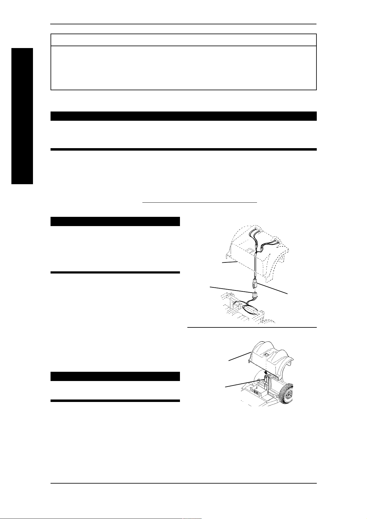
PROCEDURE 9 SHROUD/WHEELS
This Procedure Includes the Following:
Removing/Installing the Rear Shroud
Replacing Foam Filled Tires Onto Wheel Rims
Removing/Installing the Rear Wheels
Removing/Installing the Front Wheel
After ANY adjustments, repair or service and BEFORE use, make sure
that all attaching hardware is tightened securely - otherwise, injury or
damage may result.
TILLER ADJUSTMENT
REMOVING/INSTALLING THE REAR SHROUD (FIGURE 1)
REMOVING
NOTE: To install rear shroud, reverse this procedure.
WARNING
1. Remove the seat. Refer to REMOVING/INSTALLING THE SEAT in PROCEDURE 5
of this manual.
CAUTION
PANTHER MX-4
SLOWLY remove rear shroud on
PANTHER MX-4. Wiring harness for
taillights is still connected to the battery harness. Otherwise, damage may
result.
2. PANTHER MX-4 MODELS Slowly remove the rear shroud and
place on floor close to the scooter.
Disconnect taillight wiring harness
Rear Shroud
Battery
Wiring
Harnes
Taillight
Wiring
Harnes
from battery wiring harness.
3. ALL MODELS - Lift the rear shroud
off of the frame post.
ALL MODELS
REPLACING FOAM FILLED
TIRES ONTO WHEEL RIMS
WARNING
This procedure MUST be performed by a qualified technician.
Rear Shroud
Frame
Post
NOTE: During initial use of scooter, user may
experience flat spot on wheels. Flat spot will
INSTALLING THE REAR SHROUD
FIGURE 1 - REMOVING/
vanish with continuous use of scooter.
Invacare Scooters 46 Part No. 1090132 Rev F

PROCEDURE 9SHROUD/WHEELS
REMOVING/INSTALLING THE REAR WHEELS (FIGURE 2)
REMOVING
WARNING
Turn Power OFF and remove key from ignition.
1. Turn Power OFF and remove key from ignition.
2. Remove the seat. Refer to REMOVING/INSTALLING THE SEAT in PROCEDURE 5
of this manual.
3. Remove the rear shroud. Refer to REMOVING/INSTALLING THE REAR SHROUD
in this procedure of the manual.
4. Place the rear sub-frame up on blocks so that the rear tires are OFF the ground.
5. Flatten the tab on the locking tab washer that is bent against the hex head screw
(FIGURE 2, DETAIL "B").
6. Remove the hex screw that secures the rear wheel to the drive shaft.
7. Use a wheel puller if necessary to remove the EXISTING rear wheel assembly from
the drive shaft.
TILLER ADJUSTMENT
INSTALLING
NOTE: The keystock in the drive shaft MUST lineup with the cutout in the wheel hub.
1. Place keystock in cutout on drive shaft (FIGURE 2, DETAIL "A").
2. Align the three (3) mounting holes in the large washer with the three (3) mounting
holes in the wheel hub.
WARNING
NEVER use a locking tab washer more than once. ALWAYS use a NEW
locking tab washer when installing the rear wheels.
3. Align the NEW locking tab washer with the center mounting hole AND one (1) of
the outer mounting holes in the large washer.
4. Install one (1) mounting screw through the lockwasher, OUTER mounting hole in
NEW locking tab washer, large washer and wheel hub. Securely tighten.
5. Install one (1) mounting screw through the lockwasher, remaining OUTER mounting
hole in large washer and wheel hub. Securely tighten.
6. Install the rear wheel onto the drive shaft.
Part No. 1090132 Rev F 47 Invacare Scooters

PROCEDURE 9 SHROUD/WHEELS
NOTE: Use a rubber hammer if necessary to help position rear wheel completely onto the drive
shaft.
7. Install the hex screw through the MIDDLE mounting hole in the locking tab washer,
large washer and wheel hub. Securely tighten.
8. Visually inspect the hex screw and the NEW locking tab washer. Ensure one (1) of
the tabs on the NEW locking tab washer is parallel with one (1) of the flats on the
head of the hex screw (DETAIL B, FIGURE 2).
9. If one (1) of the tabs on the NEW locking tab washer is NOT parallel with one (1)
of the flats on the head of the hex screw, TIGHTEN the hex screw until the closest
flat and locking tab are parallel.
NOTE: TIGHTEN hex screw only. DO NOT loosen hex screw to make one of the tabs on the
SHROUD/WHEELS
NEW locking washer parallel.
10. Bend the parallel tab of NEW locking tab washer up tight against the hex screw
(FIGURE 2, DETAIL "B").
11. If necessary, repeat STEPS 1 - 10 for opposite rear wheel.
12. Install the rear shroud. Refer to REMOVING/INSTALLING THE REAR SHROUD in
this procedure of manual.
13. Install the seat. Refer to REMOVING/INSTALLING THE SEAT in PROCEDURE 5 of
Rear Wheel
DETAIL B
Tab Bent 90°
Large
DETAIL A
Keystock
Drive Shaft
Cutout Locking Tab
Wheel Hub
Lockwasher
Washer
Mounting Screws
Washer
Locking Tab Washer
Hex Screw
FIGURE 2 - REMOVING / INSTALLING THE REAR WHEELS
REMOVING/INSTALLING THE FRONT WHEELS (FIGURE 3)
WARNING
Turn Power OFF and remove key from ignition.
Invacare Scooters 48 Part No. 1090132 Rev F

PROCEDURE 9SHROUD/WHEELS
REMOVING
1. Turn Power OFF and remove key from ignition.
2. Place the front of the powered scooter up on blocks so that the front wheel is OFF the ground.
3. Remove the hardware that secures the front wheel to the mounting fork/front
frame. The hardware for each model is as follows:
A. For ZOOM-3 and LYNX SX-3 - Mounting screw, washers and locknut.
B. For Lynx LX-3 and LX-3
Plus
- Hex head threaded insert, spacers, washer,
lockwasher, and locknut.
C. For PANTHER LX-4 and PANTHER MX-4 - Mounting screw, lockwasher,
washer (if applicable) and locknut.
4. Remove front wheel from mounting fork/front frame.
INSTALLING
1. Secure the wheel to the mounting fork/front frame in the following manner:
WARNING
Front wheel MUST be mounted in the bottom mounting hole For ZOOM-3
and LYNX SX-3. Otherwise, injury may result.
SHROUD/WHEELS
A. For ZOOM-3 and LYNX SX-3 - with mounting screw, washers, and locknut.
B. For LYNX LX-3 and LX-3
Plus
- with hex head threaded insert, spacers,
washer, lockwasher, and locknut.
C. For PANTHER LX-4 and PANTHER MX-4 - with mounting screw,
lockwasher, washer (if applicable) and locknut.
2. Securely tighten front wheel mounting hardware.
MODELS ZOOM-3 AND LYNX SX-3 MODELS LYNX LX-3 AND LX-3
Mounting
Fork
Locknut
Washers
DO NOT USE TOP
MOUNTING HOLE
Mounting
Screw
Wheel
Mounting
Screw
Lockwasher
Washer
Spacer
Mounting
Fork
Hex Head
Threaded
Insert
Wheel
Spacer
Plus
MODELS PANTHER LX-4 AND PANTHER MX-4
Washer
Panther (MX4)
Lockwasher
Front
Frame
Wheel
Mounting
Screw
FIGURE 3 - REMOVING / INSTALLING THE FRONT WHEEL(S)
Part No. 1090132 Rev F 49 Invacare Scooters

PROCEDURE 10 TRANSPORT
This Procedure Includes the Following:
Transporting the Scooter
WARNING
After ANY adjustments, repair or service and BEFORE use, make sure that all
attaching hardware is tightened securely - otherwise, injury or damage may
result.
TRANSPORTING THE SCOOTER (FIGURES 1 AND 2)
TRANSPORT
DISASSEMBLING THE SCOOTER
NOTE: To reassemble the scooter, reverse the following steps.
1. If applicable, remove the front basket. Refer to REMOVING/INSTALLING THE
FRONT BASKET in PROCEDURE 11 of this manual.
2. Fold the back down. Refer to FOLDING/UNFOLDING THE BACK in PROCEDURE 6 of this manual.
3. Remove the seat. Refer to REMOVING/INSTALLING THE SEAT in PROCEDURE 5 of this
manual.
4. FOR ZOOM-3 MODELS ONLY - proceed to STEP 10.
5. Remove the rear shroud. Refer to REMOVING THE REAR SHROUD in PROCEDURE
9 in this procedure of the manual.
6. Remove the batteries with cable assemblies. Refer to REMOVING/INSTALLING THE BATTERIES W/CABLES in PROCEDURE 4 of this manual.
7. FOR ALL MODELS EXCEPT ZOOM-3 and PANTHER MX-4, perform the
following: (FIGURE 1)
A. For Models Built Without Delta Tillers:
1. Disconnect the BLUE connector of tiller wiring harness from BLUE connector
of controller wiring harness (DETAIL "A").
2. Disconnect the YELLOW
connector of tiller wiring harness from YELLOW connector of controller
wiring harness (DETAIL "A").
NOTE: In newer models (After 10/00), wiring harnesses from tiller to controller and connectors
have been consolidated for ease of use.
B. For Models Built With Delta Tillers:
Disconnect the ORANGE connector of tiller wiring harness from ORANGE
connector of controller wiring harness (DETAIL "B").
C. If applicable, remove the tiller wiring harness from the wire supports attached to
the controller (DETAIL "A").
Invacare Scooters 50 Part No. 1090132 Rev F

PROCEDURE 10TRANSPORT
DETAIL "A" - MODELS BUILT WITHOUT DELTA TILLERS -
EXCEPT ZOOM-3 AND PANTHER MX-4
Controller
Wiring Harness
Blue
Connectors
Yellow Connectors
Tiller Wiring Harness
Wire Supports
DETAIL "B" - MODELS BUILT WITH DELTA TILLERS
Controller Wiring
Harness
ORANGE Connectors
TRANSPORT
Tiller Wiring Harness
NOTE: Illustrations apply to Models LYNX SX-3, LYNX LX-3, LYNX LX-3
Plus
, and PANTHER LX-
4.
FIGURE 1 - TRANSPORTING THE SCOOTER - FOR ALL MODELS
EXCEPT ZOOM-3
Part No. 1090132 Rev F 51 Invacare Scooters

TRANSPORT PROCEDURE 10
8. For Panther MX-4 Models Built Before 10/00 - Without Delta Tillers (FIGURE
3):
When reassembling scooter, ensure retaining pin is properly engaged in
the hand brake cable. Otherwise, injury and/or damage may result.
A. Pull the retaining pin that secures the hand brake cable assembly together (DETAIL "A").
B. Remove the hand brake cable from the retaining tab located underneath the
NOTE: Note the position of the locknut in relation to the frame tab for proper reinstallation.
TRANSPORT
When re-assembling the hand brake cable assembly, the locknut must be positioned in front of
the frame tab (DETAILS "D" & "E").
C. Remove the threaded end of the hand brake cable from the frame tab of the rear sub-
Rear
Sub Frame
WARNING
front shroud (DETAILS "B" & "C").
frame.
DETAIL "A"
Retaining Pin
DETAIL "D" - REMOVING HAND
BRAKE CABLE
Threaded End
of Cable Assembly
Cable Assembly
DETAIL "B"
Retaining Tab
Hand Brake Cable
DETAIL "C" - HAND BRAKE
CABLE - SIDE VIEW
Rear
Hand Brake
Frame Tab of Rear
Sub-Frame
DETAIL "E" - INSTALLING HAND
BRAKE CABLE ASSEMBLY
Locknut
Threaded End
of Hand Brake
Cable Assembly
Frame Tab
Hand Brake Cable
Rear Wheel
NOTE: Side view shows location of Hand Brake Cable.
FIGURE 3 - TRANSPORTING THE SCOOTER - FOR PANTHER MX-4
MODELS BUILT BEFORE 10/00 - WITHOUT DELTA TILLERS
Invacare Scooters 52 Part No. 1090132 Rev F

PROCEDURE 10TRANSPORT
WARNING
When reassembling scooter, ensure retaining pin is properly engaged securing
the front and rear frame together. Otherwise, injury and/or damage may
result.
9. Pull retaining pin that secures the rear frame and front frame assemblies together (FIGURE
2).
10. Separate front frame assembly from the rear frame assembly (FIGURE 2).
TRANSPORT
11. Fold tiller down. Refer to
STEPS 8 AND 9 FOR ALL MODELS EXCEPT ZOOM-3
Front Frame
Assembly
Front Basket
TILLER ANGLE ADJUSTMENT in PROCEDURE 8 of this manual.
Retaining
Pin
Rear Frame
Assembly
DISASSEMBLED VIEW
Seat
Rear
Shroud
ALL MODELS EXCEPT ZOOM-3
Front Sub-Frame
Batteries
Assembly
ZOOM-3
One Piece
Frame Assembly
Rear Sub-Frame
Assembly
FIGURE 2 - TRANSPORTING THE SCOOTER
Part No. 1090132 Rev F 53 Invacare Scooters

OPTIONS/REPLACEMENT PARTSPROCEDURE 11
This Procedure Includes the Following:
Removing/Installing the Front Basket
Removing/Installing the Floor Basket
Removing/Installing the Seat Positioning Straps
Removing/Installing the Crutch/Cane Holder
Removing/Installing the Safety Flag
Replacing the Anti-Tipper Wheel and Anti-Tipper Wheel Assembly
Replacing Seat Lever
Replacing Tiller Angle Adjustment Lever
Replacing Headlight Lightbulbs
Replacing Battery Charger
OPTIONS/REPLACEMENT PARTS
After ANY adjustments, repair or service and BEFORE use, make sure
that all attaching hardware is tightened securely - otherwise, injury or
damage may result.
The front basket and the floor basket are both rated for a maximum loading capacity of 10 lbs.
REMOVING/INSTALLING THE FRONT BASKET (FIGURE 1)
1. To remove, lift up on basket and remove from mounting clips.
2. To install:
A. Align slots of basket with mounting clips on shroud of tiller.
B. Push down on basket to secure in place.
Front
Basket
WARNING
Slots
Shroud
of Tiller
Mounting
Clips
NOTE: ONLY Standard Tiller shown for clarity.
FIGURE 1 - REMOVING/INSTALLING THE FRONT BASKET
Invacare Scooters 54 Part No. 1090132 Rev F

OPTIONS/REPLACEMENT PARTS PROCEDURE 11
REMOVING/INSTALLING THE FLOOR BASKET (FIGURE 2)
1. To remove, remove the two (2) thumb screws that secure the floor basket in place.
NOTE: The front basket must be installed with angled side facing the front and the vertical side
up against the rear shroud.
2. To install, secure basket to front shroud with two (2) thumb screws. Securely
tighten.
Thumb
Screws
Floor
Basket
Front
Shroud
Front
Shroud
Floor
Basket
Rear
Shroud
Vertical
Side
SIDE VIEW
OF SCOOTER
FIGURE 2 - REMOVING/INSTALLING THE FLOOR BASKET
OPTIONS/REPLACEMENT PARTS
REMOVING/INSTALLING THE SEAT POSITIONING STRAP
(FIGURE 3)
NOTE: To remove, reverse the following procedure.
INSTALLING
1. Remove the width adjustment knob that is located either underneath or on the back
of the seat frame.
2. Slide width adjustment knob through grommet on seat positioning strap.
3. Reinstall width adjustment knob into seat frame.
4. Repeat STEPS 1-3 for opposite seat positioning strap.
Width Adjustment
Knob
Seat Frame
Grommet
Seat Positioning
Strap
FIGURE 3 -REMOVING/INSTALLING THE SEAT POSITIONING STRAP
Part No. 1090132 Rev F 55 Invacare Scooters

REMOVING/INSTALLING THE CRUTCH/CANE HOLDER
(FIGURE 4)
NOTE: The Crutch/Cane Holder, Safety Flag, and Oxygen Holder all install into the accessory tube; ONLY
one (1) of these may be installed at a time. These accessories are NOT available on the ZOOM-3.
NOTE: To remove, reverse the following
procedure.
WARNING
The installation of the crutch/cane
holder onto the back of the
scooter seat significantly increases
the length of the scooter. When
turning the scooter or swiveling
the scooter seat, it is important to
take note of this increased length -
OPTIONS/REPLACEMENT PARTS
otherwise, injury and/or damage to
the
surrounding property may result.
OPTIONS/REPLACEMENT PARTSPROCEDURE 11
Seat
Crutch/
Cane
Holder
Hook
Base
Accessory
Tube
Mounting
Screw
FIGURE 4 - REMOVING/
INSTALLING THE CRUTCH/CANE
HOLDER
INSTALLING
1. Install the crutch/cane holder into the accessory tube located on the back of the
seat.
2.. Install mounting screw to secure the crutch/cane holder in place. Securely tighten.
3. Align slot on base with hook on crutch/cane holder and slide base down into position.
REMOVING/INSTALLING THE SAFETY FLAG (FIGURE 5)
NOTE: To remove, reverse the following
procedure.
WARNING
The installation of the safety flag
onto the back of the scooter seat
significantly increases the length of
the scooter. When turning the
scooter or swiveling the scooter seat,
it is important to take note of this
increased length - otherwise, injury
and/or damage to the surrounding
property may result.
Safety
Flag
Bracket
INSTALLING THE SAFETY FLAG
Seat
Accessory
Tube
Mounting
Screw
FIGURE 5 - REMOVING/
INSTALLING
1. Install the bracket into the accessory tube located on the back of the seat.
2. Install mounting screw to secure the bracket in place. Securely tighten.
3. Install safety flag into bracket.
Invacare Scooters 56 Part No. 1090132 Rev F

OPTIONS/REPLACEMENT PARTS PROCEDURE 11
REPLACING ANTI-TIPPER WHEELS AND ANTI-TIPPER
WHEEL ASSEMBLY (FIGURE 6)
WARNING
DO NOT operate scooter without the anti-tippers being installed, if so
equipped. Anti-tippers MUST BE attached at all times.
ANTI-TIPPER WHEELS
OPTIONS/REPLACEMENT PARTS
1. Perform one of the following:
A. For ZOOM-3 - remove the screw
and locknut that secures the antitipper wheels to the frame.
B. For all other models - Remove the
cotter pin and washer that secure the
anti-tipper wheel to the frame.
2. Install NEW wheels and secure with
EXISTING hardware.
ANTI-TIPPER WHEEL
ASSEMBLY
NOTE: Anti-tipper wheel assemblies are only
found on the LYNX LX-3, LYNX LX-3
PANTHER LX-4 models.
NOTE: To replace anti-tipper wheels, refer to
REPLACING ANTI-TIPPER WHEELS in this
procedure of the manual.
1. Remove the quick-release pin that
secure the anti-tipper assembly to the
rear frame assembly.
2. Remove the anti-tipper wheel assembly.
3. Install NEW anti-tipper wheel assembly.
Plus
and
ZOOM-3
Frame
Locknut
Anti-Tipper
Screw
Rear Shroud
Cotter Pin
Anti-Tipper
NOTE: Rear wheel removed for clarity.
Rear
Sub-Frame
Wheel
Frame
Wheel
Washer
Quick-
Release
Pin
WARNING
When installing quick-release pin,
ensure locking pin is protruding
through bottom of sub-frame assembly.
4. Secure NEW anti-tipper wheel
assembly to sub-frame with quickrelease pin.
Part No. 1090132 Rev F 57 Invacare Scooters
FIGURE 6 - REPLACING ANTI-
TIPPER WHEELS AND ANTI-
TIPPER WHEEL ASSEMBLY
Anti-Tipper
Assembly
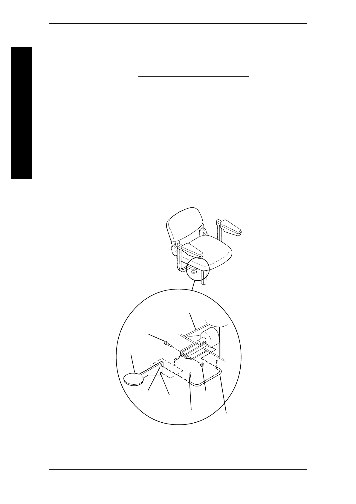
PROCEDURE 11
REPLACING SEAT LEVER
(FIGURE 7)
NOTE: The seat lever is NOT available on ZOOM-3.
OPTIONS/REPLACEMENT PARTS
1. Remove the seat. Refer to
of this manual.
2. Place seat upside down on ground/floor.
3. Remove cotter pin that secures the seat lever to the connecting pin.
4. Remove the mounting screw and locknut that secure the seat lever to the seat plate.
5. Install NEW seat lever.
6. Install EXISTING mounting screw through seat plate and bottom hole of seat lever
and secure with locknut. Securely tighten.
7. Install connecting pin through top hole on seat lever.
OPTIONS/REPLACEMENT PARTS
8. Install cotter pin in the end of the connecting pin to secure seat lever in place.
REMOVING/INSTALLING THE SEAT in PROCEDURE 5
Seat
Plate
Mounting
Screw
Seat Lever
Top
Hole
Bottom
Hole
Cotter Pin
Locknut
Connecting
Pin
FIGURE 7 - REPLACING SEAT LEVER
Invacare Scooters 58 Part No. 1090132 Rev F

OPTIONS/REPLACEMENT PARTS PROCEDURE 11
REPLACING TILLER ANGLE ADJUSTMENT LEVER
(FIGURE 8)
NOTE: The tiller angle adjustment lever is
NOT available on ZOOM-3.
1. Adjust the tiller so that the position of
the tiller is in-between adjustment
holes.
NOTE: This adjustment allows the plunger to
be fixed in the fully extended position.
Seat
Lever
Pin
Plunger
Tiller
Adjustment
Holes
OPTIONS/REPLACEMENT PARTS
2. Remove the retaining ring.
3. Remove the pin that secures the
Retaining
Ring
adjustment lever in place.
Adjustment
Holes
4. Remove the adjustment lever from the
plunger.
5. Install NEW adjustment lever onto
plunger.
Position tiller in-between
adjustment holes
(STEP 1)
FIGURE 8 - REPLACING TILLER
ANGLE ADJUSTMENT LEVER
6. Install pin through adjustment lever and plunger and secure in place with retaining ring.
7. Adjust tiller to one (1) of the three (3), or five (5) adjustment holes. Refer to
TILLER
ANGLE ADJUSTMENT in PROCEDURE 8 of this manual.
REPLACING HEADLIGHT LIGHTBULBS
MODELS LYNX LX-3 AND PANTHER LX-4 (FIGURE 9)
1. Remove the two (2) mounting screws that secure the headlight assembly to the
housing.
2. Remove the plug from the headlight
assembly.
3. Remove the EXISTING lightbulb from
the plug.
LYNX LX-3 AND PANTHER LX-4
Housing
Lightbulb
Mounting Screws
4. Install the NEW lightbulb into the plug.
5. Reinstall plug into headlight assembly.
6. Resecure headlight assembly to the
housing with EXISTING mounting
screws. Securely tighten.
Headlight Assembly
Plug
FIGURE 9 - REPLACING
HEADLIGHT LIGHTBULBS
MODELS LYNX LX-3 AND
PANTHER LX-4
Part No. 1090132 Rev F 59 Invacare Scooters
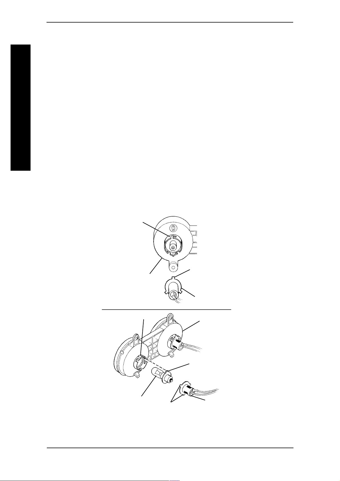
MODEL PANTHER MX-4 (FIGURE 10)
NOTE: Prongs on lightbulb plug are not equally spaced around diameter. Once removed,
lightbulb plug can only be installed with prongs in the orientation in which they were removed.
1. Before removing lightbulb plug, place a scribe mark on a prong and the slot in which
it is positioned in. See DETAIL "A".
NOTE: When reassembling, the scribe mark will help align the prongs with the proper corresponding slots on the headlight assembly.
2. To remove lightbulb plug, twist lightbulb plug COUNTERCLOCKWISE and remove
from headlight assembly.
3. Remove lightbulb from headlight assembly.
4. To install light bulb, align prong of NEW lightbulb with the slot in the head light
assembly and insert.
OPTIONS/REPLACEMENT PARTS
5. Install plug into headlight assembly at the orientation noted from above and twist
CLOCKWISE.
OPTIONS/REPLACEMENT PARTSPROCEDURE 11
DETAIL "A" - BACK VIEW OF HEADLIGHT ASSEMBLY
Place scribe
mark near
corresponding slot
of headlight
assembly.
Place scribe
Partial View of
Headlight
Assembly
Notch
mark on
prong.
Lightbulb Plug
Headlight
Assembly
Prong
Lightbulb
Prongs
Plug
FIGURE 10 - REPLACING HEADLIGHT LIGHTBULBS
MODEL PANTHER MX-4
Invacare Scooters 60 Part No. 1090132 Rev F
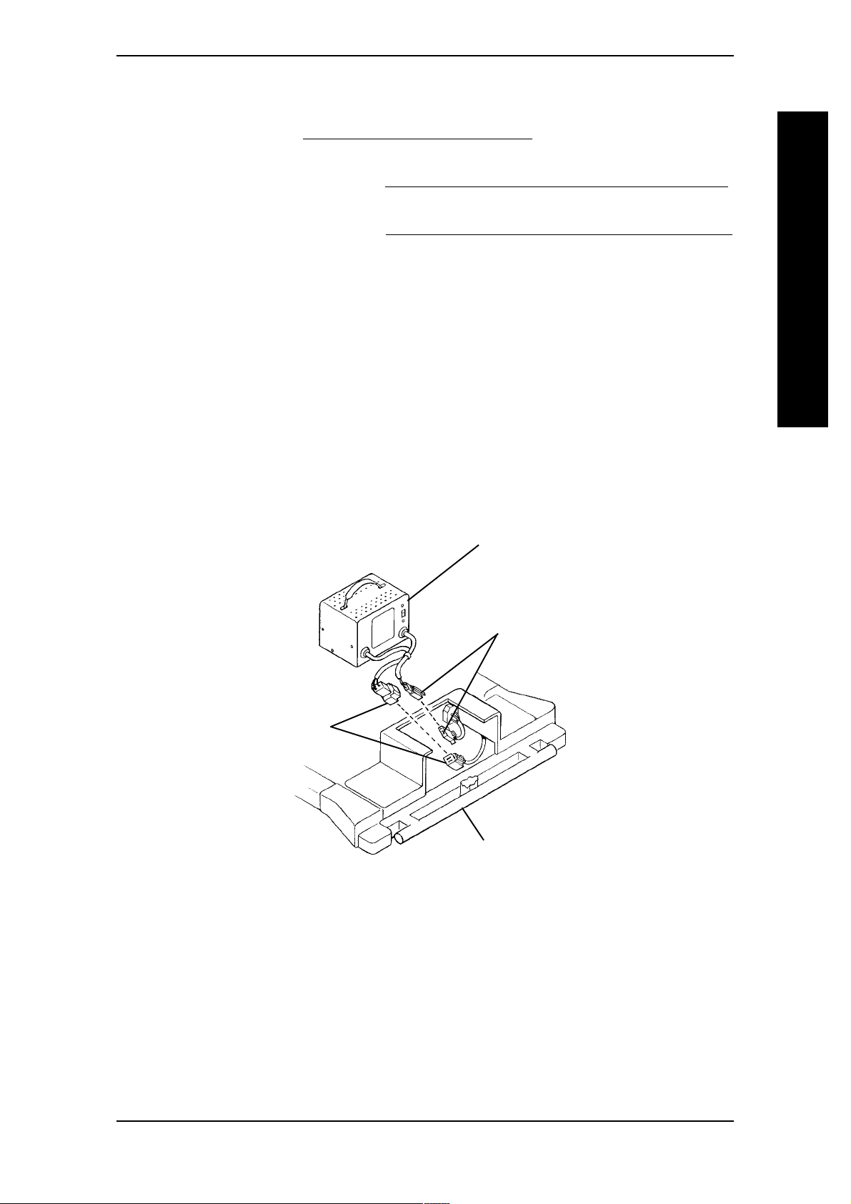
OPTIONS/REPLACEMENT PARTS PROCEDURE 11
REPLACING ON-BOARD BATTERY CHARGER (FIGURE 11)
1. Remove seat. Refer to REMOVING/INSTALLING SEAT in PROCEDURE 5 of this
manual.
2. Remove the rear shroud. Refer to REMOVING/INSTALLING THE REAR SHROUD
in PROCEDURE 9 of this manual.
3. Remove the floor basket. Refer to REMOVING/INSTALLING THE FLOOR BASKET
in this procedure of the manual.
4. Pull on-board battery charger partially out of front shroud.
5. Disconnect blue connector of on-board battery charger from blue connector of
battery wiring harness.
6. Disconnect white connector of on-board battery charger from white connector of
battery wiring harness.
7. Remove the EXISTING on-board battery charger.
8. Install NEW on-board battery charger by reversing STEPS 1-7.
On-Board
Battery
Charger
OPTIONS/REPLACEMENT PARTS
White
Connectors
Blue
Connectors
Front
Shroud
FIGURE 11 - REPLACING ON-BOARD BATTERY CHARGER
Part No. 1090132 Rev F 61 Invacare Scooters

NOTES
NOTES
NOTES
Invacare Scooters 62 Part No. 1090132 Rev F

LIMITED WARRANTY
LIMITED WARRANTY
PLEASE NOTE: THE WARRANTY BELOW HAS BEEN DRAFTED TO COMPLY WITH
FEDERAL LAW APPLICABLE TO PRODUCTS MANUFACTURED AFTER JULY 4, 1975.
This warranty is extended only to the original purchaser/user of our products.
This warranty gives you specific legal rights and you may also have other legal rights which
vary from state to state.
Invacare warrants this product to be free from defects in materials and workmanship for a
period of eighteen (18) months on electrical and transaxle and three (3) years on frame
from date of purchase. If within such warranty period any such product shall be proven to
be defective, such product shall be repaired or replaced at Invacare's option. This warranty
does not include any labor or shipping charges incurred in replacement part installation or
repair of any such product. Invacares sole obligation and your exclusive remedy under this
warranty shall be limited to such repair and/or replacement.
For warranty service, please contact the dealer from whom you purchased your Invacare
product. In the event you do not receive satisfactory warranty service, please write directly
to Invacare at the address on the back cover, provide dealers name, address, date of
purchase, indicate nature of the defect and, if the product is serialized, indicate the serial
number. Do not return products to our factory without our prior consent.
LIMITED W
ARRANTY
LIMITATIONS AND EXCLUSIONS: THE FOREGOING WARRANTY SHALL NOT
APPLY TO SERIAL NUMBERED PRODUCTS IF THE SERIAL NUMBER HAS BEEN
REMOVED OR DEFACED, PRODUCTS SUBJECTED TO NEGLIGENCE, ACCIDENT,
IMPROPER
OPERATION, MAINTENANCE OR STORAGE, PRODUCTS MODIFIED WITHOUT
INVACARES EXPRESS WRITTEN CONSENT (INCLUDING, BUT NOT LIMITED TO,
MODIFICATION THROUGH THE USE OF UNAUTHORIZED PARTS OR
ATTACHMENTS; PRODUCTS DAMAGED BY REASON OF REPAIRS MADE TO ANY
COMPONENT WITHOUT THE SPECIFIC CONSENT OF INVACARE, OR TO A
PRODUCT DAMAGED BY CIRCUMSTANCES BEYOND INVACARES CONTROL,
AND SUCH EVALUATION WILL BE SOLELY DETERMINED BY INVACARE. THE
WARRANTY SHALL NOT APPLY TO PROBLEMS ARISING FROM NORMAL WEAR
OR FAILURE TO
ADHERE TO THE THESE INSTRUCTIONS.
THE FOREGOING EXPRESS WARRANTY IS EXCLUSIVE AND IN LIEU OF ANY
OTHER WARRANTIES WHATSOEVER, WHETHER EXPRESS OR IMPLIED, INCLUDING THE IMPLIED WARRANTIES OF MERCHANTABILITY AND FITNESS FOR A
PARTICULAR PURPOSE, AND THE SOLE REMEDY FOR VIOLATIONS OF ANY
WARRANTY
WHATSOEVER, SHALL BE LIMITED TO REPAIR OR REPLACEMENT OF THE
DEFECTIVE PRODUCT PURSUANT TO THE TERMS CONTAINED HEREIN, THE
APPLICATION OF ANY IMPLIED WARRANTY WHATSOEVER SHALL NOT EXTEND
BEYOND THE DURATION OF THE EXPRESS WARRANTY PROVIDED HEREIN.
INVACARE SHALL NOT BE LIABLE FOR ANY CONSEQUENTIAL OR INCIDENTAL
DAMAGES WHATSOEVER.
THIS WARRANTY SHALL BE EXTENDED TO COMPLY WITH STATE/PROVINCIAL
LAWS AND REQUIREMENTS.
Part No. 1090132 Rev F 63 Invacare Scooters

Invacare Corporation www.invacare.com
USA Canada
One Invacare Way 5970 Chedworth Way Invacare is a registered trademark of
Elyria, Ohio USA Mississauga, Ontario Invacare Corporation.
44036-2125 L5R 3T9, Canada ©
800-333-6900 905-890-8838
2000 Invacare Corporation
Part No. 1090132 Rev F (1) 1/03
Printed in TAIWAN
 Loading...