

Page 1
Service Manual
Pronto® M71
with SureStep™
™
DEALER: Keep this manual. The
procedures in this manual MUST be
performed by a qualified technician.
For more information regarding
Invacare products, parts, and services,
please visit www.invacare.com
Page 2

REFERENCE DOCUMENTS
WARNING
DO NOT OPERATE THIS EQUIPMENT WITHOUT FIRST READING
AND UNDERSTANDING THIS MANUAL. IF YOU ARE UNABLE TO
UNDERSTAND THE WARNINGS, CAUTIONS, AND
INSTRUCTIONS, CONTACT A HEALTHCARE PROFESSIONAL,
DEALER OR A QUALIFIED TECHNICIAN BEFORE ATTEMPTING
TO USE THIS EQUIPMENT - OTHERWISE INJURY OR DAMAGE
MAY RESULT.
PROCEDURES OTHER THAN THOSE DESCRIBED IN THIS
MANUAL MUST
BE PERFORMED BY A QUALIFIED TECHNICIAN.
IF WHEELCHAIR IS EQUIPPED WITH POWER TILT ONLY OR THE
FORMULA PTO PLUS SEATING SYSTEM, REFER TO POWER TILT
ONLY FOR PRONTO M71 AND M91 OWNER’S MANUAL, PART
NUMBER 1118362 OR TO FORMULA PTO PLUS POWERED
SEATING SERVICE MANUAL, PART NUMBER 1125031 TO
PERFORM THE FOLLOWING PROCEDURES:
• TILTING THE SEAT ASSEMBLY (REPLACES REMIVNG/
INSTALLING THE SEAT ASSEMBLY IN THIS MANUAL)
• ADJUSTING SEAT HEIGHT
• ADJUSTING SEAT POSITION
• CHARGING THE BATTERIES
REFERENCE DOCUMENTS
DOCUMENT PART NUMBER
M71 with MK5™Owners Manual BEFORE 1/24/06 1106631
M71 with MK
EX™Electronics Owners Manaul 1114808
MK
5
NX™Electronics Owners Manual 1110532
MK
5
MK6i™Field Reference Guide 1141471
MK6i Service Manual 1143203
MKIV™RII Electronics Owners Manual 1095272
M71 Base with MK6i Owners Manual 1143240
NOTE: Updated versions of this manual are available on www.invacare.com.
Pronto® M71™ 2 Part No 1118377
Owners Manual AFTER 1/23/06 1141449
5
Page 3

TABLE OF CONTENTS
TABLE OF CONTENTS
REFERENCE DOCUMENTS ................................................................. 2
SPECIAL NOTES ................................................................................ 8
LABEL LOCATIONS ......................................................................... 10
Wiring Label on M71 Standard with Battery Covers.......................................................................10
M71 with PTO+ Labels ...........................................................................................................................12
TYPICAL PRODUCT PARAMETERS .................................................. 13
SECTION 1—GENERAL GUIDELINES ................................................. 14
Repair or Service Information ...............................................................................................................14
Operation Information............................................................................................................................14
Tire Pressure .............................................................................................................................................15
Electrical .....................................................................................................................................................15
Grounding Instructions.......................................................................................................................15
Batteries......................................................................................................................................................15
SECTION 2—EMI INFORMATION ..................................................... 16
SECTION 3—SAFETY INSPECTION/TROUBLESHOOTING .................... 18
Safety Inspection Checklists...................................................................................................................18
Inspect/Adjust .......................................................................................................................................18
Troubleshooting........................................................................................................................................19
Troubleshooting - Electrical ..............................................................................................................19
Wheels ...................................................................................................................................................24
Troubleshooting - Common .............................................................................................................24
Troubleshooting - Motor/Gearbox/Brake .....................................................................................24
Troubleshooting - Battery .................................................................................................................26
Troubleshooting - Battery Charger.................................................................................................26
Checking Battery Charge Level.............................................................................................................27
Field Load Test..........................................................................................................................................28
Motor Testing.......................................................................................................................................29
Part No 1118377 3 Pronto® M71™
Page 4

TABLE OF CONTENTS
TABLE OF CONTENTS
SECTION 4—SEAT ASSEMBLY .......................................................... 30
Removing/Installing the Seat Assembly................................................................................................30
Removing Seat ......................................................................................................................................30
Installing Seat.........................................................................................................................................30
Adjusting the Seat Height .......................................................................................................................31
Removing/Installing the Adjustable Height Tubes.............................................................................33
Adjustable ASBA Seat Service Procedures.........................................................................................35
Removing/Installing the Seat Pan ......................................................................................................35
Adjusting the Seat Width ...................................................................................................................35
Adjusting the Seat Depth ...................................................................................................................36
Removing/Installing Side Rails............................................................................................................38
Replacing the Seat Frame ...................................................................................................................40
Removing/Installing the Back Canes ................................................................................................41
Replacing Seat Positioning Strap.......................................................................................................42
Adjusting the Back Angle....................................................................................................................43
ASBA Seat Service Procedures .............................................................................................................44
Removing/Installing the Seat Pan ......................................................................................................44
Changing the Seat Width/Depth ......................................................................................................45
Replacing the Seat Frame ...................................................................................................................45
Replacing the Seat Positioning Strap................................................................................................46
Removing/Installing the Back Upholstery .......................................................................................46
Removing/Installing/Changing the Back Cane Height ..................................................................46
Adjusting the Back Angle....................................................................................................................50
Van Seat Service Procedures .................................................................................................................51
Adjusting the Back Angle....................................................................................................................51
Adjusting the Seat Position on Van Seat Frame............................................................................51
Adjusting the Van Seat Back Depth.................................................................................................53
Part No 1118377 4 Pronto® M71™
Page 5

TABLE OF CONTENTS
TABLE OF CONTENTS
SECTION 5—ARMS ......................................................................... 54
Arm Service Procedures for Van Seat.................................................................................................54
Removing/Installing Van Seat Arm ...................................................................................................54
Adjusting Van Seat Arm Width ........................................................................................................54
Adjusting Van Seat Arm Angle..........................................................................................................55
Adjusting Van Seat Arm Height ........................................................................................................55
Replacing Van Seat Armrest Pads (Wheelchairs Built before October 2003) ......................56
Replacing Van Seat Armrest Plate (Wheelchairs Built before October 2003)......................56
Replacing Van Seat Armrest Pad Assembly (Wheelchairs Built After October 2003)........57
Arm Service Procedures for ASBA or Adjustable ASBA Seat.......................................................58
Removing/Installing Flip Back Armrest............................................................................................58
Adjusting the Flip Back Armrest.......................................................................................................58
SECTION 6—WHEELS ....................................................................... 60
Replacing the Front/Rear Casters.........................................................................................................60
Adjusting Caster Assembly.....................................................................................................................61
Removing/Installing the Front/Rear Caster Assemblies...................................................................62
Removing ...............................................................................................................................................62
Installing..................................................................................................................................................62
Removing/Installing the Front Headtube Assembly..........................................................................62
Removing/Installing the Drive Wheel ..................................................................................................63
Removing the Drive Wheel...............................................................................................................63
Installing the Drive Wheel .................................................................................................................63
Replacing the 2-Piece Wheel Rim and/or the Foam Filled or Pneumatic Tires.........................64
Part No 1118377 5 Pronto® M71™
Page 6

TABLE OF CONTENTS
TABLE OF CONTENTS
SECTION 7—FRONT RIGGINGS/FOOTBOARD .................................... 66
Installing/Removing Front Riggings .......................................................................................................66
Installing..................................................................................................................................................66
Removing ...............................................................................................................................................66
Adjusting Footrest Height ......................................................................................................................67
Model PHWH93 Front Riggings .......................................................................................................67
Model PH904A and PHAL4A Front Riggings ................................................................................67
Replacing Heel Loops ..............................................................................................................................68
Raising/Lowering Elevating Front Riggings ..........................................................................................68
Adjusting/Replacing Telescoping Front Rigging Supports................................................................68
Van Seat..................................................................................................................................................68
ASBA Seat..............................................................................................................................................70
Adjustable ASBA Seat .........................................................................................................................70
Removing/Installing the Footboard Assembly....................................................................................71
Removing ...............................................................................................................................................71
Installing..................................................................................................................................................71
Angle/Depth/Height Adjustment of the Footboard Assembly.......................................................72
Angle Adjustment ................................................................................................................................72
Depth Adjustment ...............................................................................................................................72
Height Adjustment...............................................................................................................................73
SECTION 8—SHROUDS/FRAME ........................................................ 74
Removing/Installing the Shrouds ...........................................................................................................74
Disassembling/Reassembling the Side Frame Assembly...................................................................76
Removing/Installing the Pivot Tube ......................................................................................................76
Removing/Installing the Walking Beam................................................................................................77
Replacing the Side Frame........................................................................................................................77
Removing/Installing the SureStep Springs ...........................................................................................78
SECTION 9—MOTORS ..................................................................... 80
Removing/Installing the Motor ..............................................................................................................80
Removing/Installing the Motor Release Lever ...................................................................................81
Replacing Internal Motor Brushes ........................................................................................................82
Inspecting/Replacing External Motor Brushes ...................................................................................84
Electro-Mechanical Parking Brake Testing..........................................................................................85
Pronto® M71™ 6 Part No 1118377
Page 7

SECTION 10—BATTERIES/CHARGER ................................................ 86
Warnings For Handling and Replacing Batteries ...............................................................................86
Using the Proper Batteries.....................................................................................................................87
Removing/Installing Batteries From/Into Battery Tray ....................................................................88
Removing Batteries..............................................................................................................................89
Installing Batteries................................................................................................................................89
Connecting/Disconnecting Battery Cables.........................................................................................91
Connecting Battery Cables................................................................................................................91
Disconnecting Battery Cables...........................................................................................................93
Replacing the On-Board Battery Charger Fuse.................................................................................94
Replacing the On-Board Battery Charger ..........................................................................................95
SECTION 11—CONTROLLER AND JOYSTICK .................................... 97
Disconnecting/Connecting the Joystick...............................................................................................97
Disconnecting .......................................................................................................................................97
Connecting ............................................................................................................................................97
Removing/Installing the Joystick ............................................................................................................98
Van Seat Models ...................................................................................................................................98
ASBA and Adjustable ASBA Models................................................................................................99
Replacing the MKIV RII Controller ................................................................................................... 100
Replacing the MK5-NX or MK660 ACC Controller .................................................................... 102
SECTION 12—DISASSEMBLING/ASSEMBLING THE M71 .................... 103
Disassembling/Assembling the Wheelchair ..................................................................................... 103
Disassembling the Wheelchair....................................................................................................... 103
Assembling the Wheelchair............................................................................................................ 106
SECTION 13—TRANSPORT READY PACKAGE ................................ 109
About Transport Ready Packages...................................................................................................... 110
Compliance Information ...................................................................................................................... 110
Specifications...................................................................................................................................... 110
Securing the Wheelchair to the Vehicle .......................................................................................... 111
Positioning the Wheelchair in the Vehicle.................................................................................. 111
Securement Points............................................................................................................................ 112
Securing the Wheelchair ................................................................................................................. 112
Securing the Occupant......................................................................................................................... 113
Wheelchair-Anchored Belts........................................................................................................... 113
Vehicle-Anchored Belts................................................................................................................... 114
Seating System ................................................................................................................................... 114
Positioning Belts ................................................................................................................................ 115
LIMITED WARRANTY ................................................................... 116
Part No 1118377 7 Pronto® M71™
Page 8

SPECIAL NOTES
SPECIAL NOTES
Signal words are used in this manual and apply to hazards or unsafe practices which
could result in personal injury or property damage. Refer to the table below for
definitions of the signal words.
SIGNAL WORD MEANING
Danger indicates an imminently hazardous situation which, if not avoided,
DANGER
WARNING
CAUTION
THE INFORMATION CONTAINED IN THIS DOCUMENT IS SUBJECT TO
CHANGE WITHOUT NOTICE.
WHEELCHAIR USER
As a manufacturer of wheelchairs, Invacare endeavors to supply a wide variety of
wheelchairs to meet many needs of the end user. However, final selection of the
type of wheelchair to be used by an individual rests solely with the user and his/her
healthcare professional capable of making such a selection.
The seat positioning strap is a positioning belt ONLY. It is not designed for use as a
safety device withstanding high stress loads such as auto or aircraft safety belts. If
signs of wear appear, belt must be replaced immediately.
will result in death or serious injury.
Warning indicates a potentially hazardous situation which, if not avoided,
could result in death or serious injury.
Caution indicates a potentially hazardous situation which, if not avoided,
may result in property damage.
NOTICE
WHEELCHAIR TIE-DOWN RESTRAINTS AND SEAT RESTRAINTS (TRRO OR
TRBKTS)
TRRO includes four factory-installed transport brackets and a wheelchair anchored
pelvic belt. TRRO has been crash-tested in accordance with ANSI/RESNA WC Vol 1
Section 19 Frontal Impact Test requirements for wheelchairs with a 168 lb crash
dummy, which corresponds to a person with a weight of 114 to 209 lbs.
TRBKTS includes four factory-installed wheelchair transport brackets. TRBKTS has
not been crash-tested in accordance with WC 19. Use these transport brackets only
to secure an unoccupied wheelchair during transport.
As of this date, the Department of Transportation has not approved any tie-down
systems for transportation of a user while in a wheelchair, in a moving vehicle of any
type. It is Invacare’s position that users of wheelchairs should be transferred into
appropriate seating in vehicles for transportation and use be made of the restraints
made available by the auto industry. Invacare cannot and does not recommend any
wheelchair transportation systems.
Refer to Transport Ready Package
on page 109 for more information about
transporting the wheelchair.
SEAT POSITIONING STRAP
It is the obligation of the Dealers, Therapists and other Healthcare Professionals to
determine if a seat positioning strap is required to ensure the safe operation of this
equipment by the user. Serious injury can occur in the event of a fall from a
powered wheelchair.
Pronto® M71™ 8 Part No 1118377
Page 9

SPECIAL NOTES
TRRO AND TRBKTS WARNINGS
Only use the transport brackets included with TRRO and TRBKTS for the purposes
described in this manual.
Battery support brackets MUST be installed at all times. Otherwise, the wheelchair
will not be WC/19 compliant. Refer to Removing/Installing Batteries From/Into
Battery Tray on page 88.
WARNING
Invacare products are specifically designed and manufactured for use in conjunction
with Invacare accessories. Accessories designed by other manufacturers have not
been tested by Invacare and are not recommended for use with Invacare products.
Wheelchairs should be examined during maintenance for signs of corrosion (water
exposure, incontinence, etc). Electrical components damaged by corrosion should
be replaced IMMEDIATELY.
Wheelchairs that are used by incontinent users and/or are frequently exposed to
water may require replacement of electrical components more frequently.
Part No 1118377 9 Pronto® M71™
Page 10
LABEL LOCATIONS
LABEL LOCATIONS
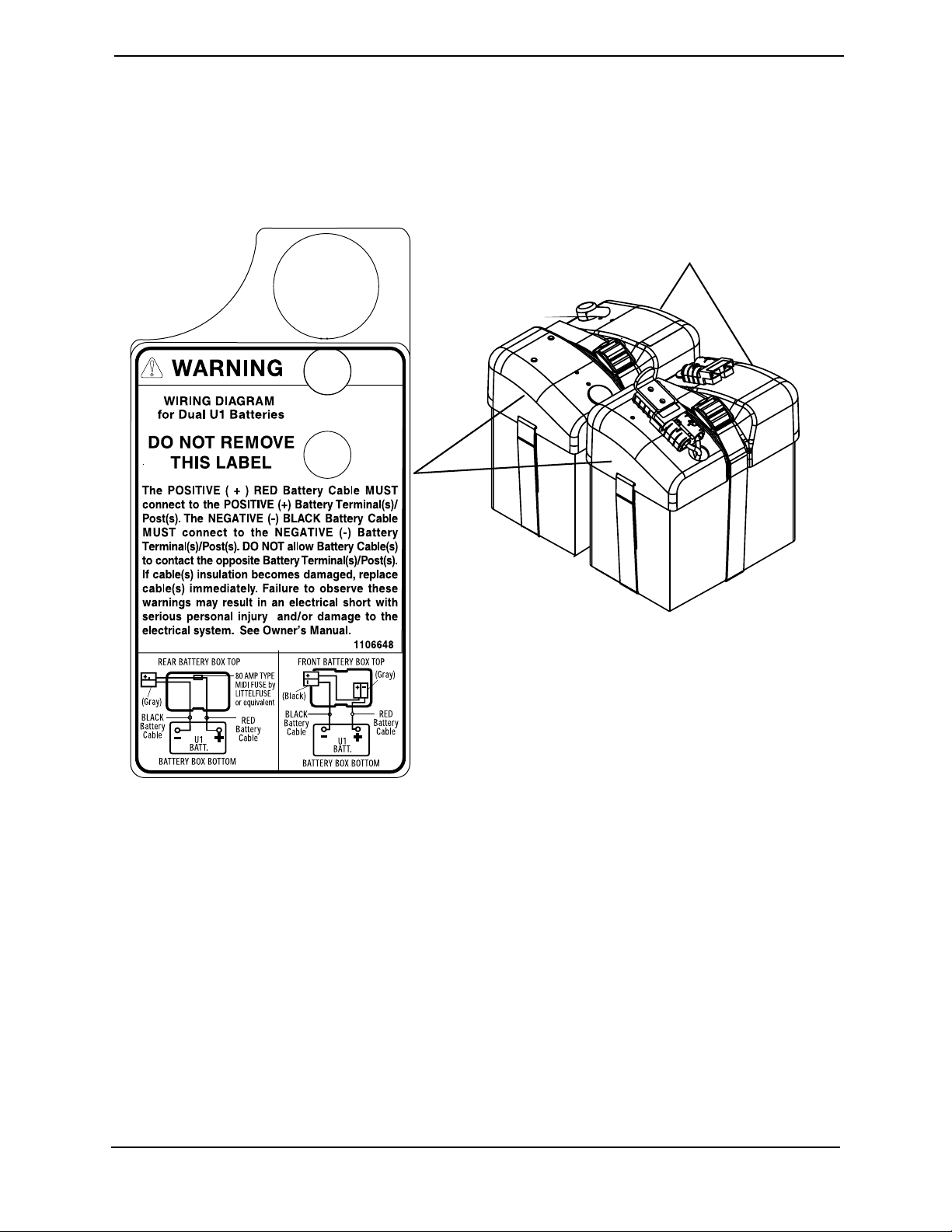
Wiring Label on M71 Standard with Battery Covers
Battery Covers
NOTE: Label under battery cover.
Pronto® M71™ 10 Part No 1118377
Page 11
Serial Number is located
underneath seat in rear, should
not have to remove seat.
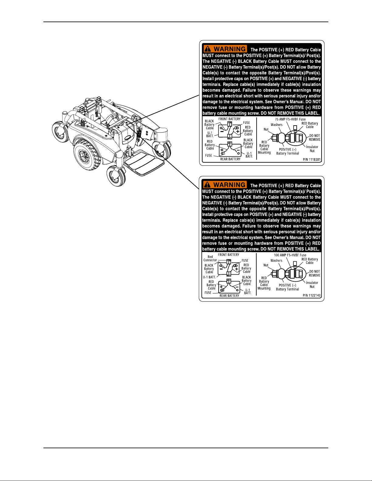
LABEL LOCATIONS
One of these battery wiring
labels is in this location.
Part No 1118377 11 Pronto® M71™
Page 12
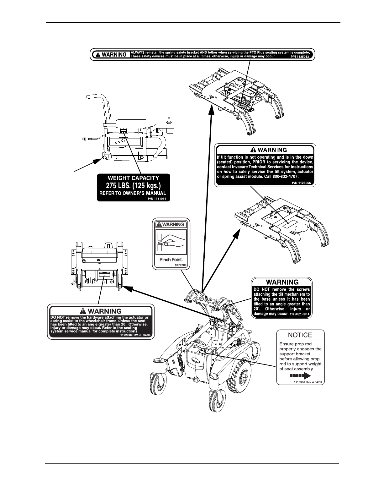
LABEL LOCATIONS
M71 with PTO+ Labels
Serial
Number
Located
HERE
rear view of
actuator
Pronto® M71™ 12 Part No 1118377
Page 13

TYPICAL PRODUCT PARAMETERS
TYPICAL PRODUCT PARAMETERS
18 INCH VAN 20 INCH VAN ASBA ADJUSTABLE
ASBA
SEAT WIDTH: 18 inches 20 inches 16 to 20 inches
SEAT DEPTH: 16 to 18 inches 18 to 20 inches 16 to 20 inches
BACK HEIGHT: 18 inches 18 inches 16 to 20 inches
BACK ANGLE RANGE: N/A N/A 80° to 100° 85° to 105°
UPHOLSTERY: Grey Cloth, Grey Vinyl, Tan Vinyl Black Nylon Back with Seat Pan
SEAT-TO-FLOOR: 21 to 23 inches (cushion not compressed) 18 to 20 inches (to seat pan)
OVERALL WIDTH OF BASE
(W/O JOYSTICK): 24 inches
OVERALL HEIGHT: 48 inches
OVERALL LENGTH
FOOTBOARD FOLDED:
FOOTBOARD EXTENDED:
WEIGHT
WITHOUT BATTERIES:
WITH BATTERIES:
SHIPPING (WITHOUT
BATTERIES):
DRIVE WHEELS/TIRES
(PNEUMATIC) 10 x 3½ inches
CASTERS W/PRECISION
SEALED BEARINGS: 6 x 2 inches
FOOTRESTS/LEGRESTS: Flip Up, Depth and Height Adjustable, Footboard, Swingaway Front Rigging,
ARMRESTS: Adjustable Width, Angle and Height
BATTERY REQUIREMENTS: Use only U1 batteries (Quantity - 2)
WEIGHT LIMITATION: up to 300 pounds
INCLINE CAPABILITY: 9°
PERFORMANCE
SPEED:
TURNING RADIUS:
*RANGE (VARIABLE):
OVERALL WIDTH OF BASE
(W/O JOYSTICK): 300 pounds
1
35 inches
39½ inches
150 pounds
203 pounds
200 pounds
Elevating Legrest
up to 4 MPH
19½ inches with footboard
up to 12 miles
1. Includes seating systems and accessories.
*NOTE: Values for range are calculated for maximum chair weight rating using largest batteries
applicable (U1), per test procedures described in ANSI/RESNA WC/VOL2-1998 Section 4 and
meet federal reimbursement requirements for this product. While considered typical, they are
derived based on certain ideal conditions. Variances in battery condition, user weight, usage
pattern or overall terrain conditions will result in actual values for range that differ from these
stated values. Users should become accustomed to how their unique conditions impact their
individual results. Users should become familiar with the battery discharge indicator on the
joystick to determine the range of their wheelchair. Refer to Connecting/Disconnecting Battery
Cables on page 91 for more information about the battery discharge indicator.
Part No 1118377 13 Pronto® M71™
Page 14

SECTION 1—GENERAL GUIDELINES
SECTION 1—GENERAL GUIDELINES
WARNING
SECTION 1 - GENERAL GUIDELINES contains important information for the safe
operation and use of this product. DO NOT use this product or any available
optional equipment without first completely reading and understanding these
instructions and any additional instructional material such as Owner’s Manuals,
Service Manuals or Instruction Sheets supplied with this product or optional
equipment. If you are unable to understand the Warnings, Cautions or Instructions,
contact a healthcare professional, dealer or technical personnel before attempting
to use this equipment - otherwise, injury or damage may occur.
Repair or Service Information
Set-up of the Electronics Control Unit is to be performed ONLY by a qualified technician.
The final adjustments of the controller may affect other activities of the wheelchair.
Damage to the equipment could occur if improperly set-up or adjusted.
DO NOT service or adjust your wheelchair while occupied, unless otherwise noted.
Wheelchairs should be examined during maintenance for signs of corrosion (water
exposure, incontinence, etc.). Electrical components damaged by corrosion should be
replaced IMMEDIATELY.
Wheelchairs that are used by incontinent users and/or are frequently exposed to water
may require replacement of electrical components more frequently.
Operation Information
Performance adjustments should only be made by professionals of the healthcare field or
persons fully conversant with this process and the driver's capabilities. Incorrect settings
could cause injury to the driver, bystanders, damage to the wheelchair and to
surrounding property.
After the wheelchair has been set-up, check to make sure that the wheelchair performs to
the specifications entered during the set-up procedure. If the wheelchair does NOT
perform to specifications, turn the wheelchair OFF immediately and reenter set-up
specifications. Repeat this section until the wheelchair performs to specifications.
DO NOT adjust the rear seat posts higher than the front seat posts.
Avoid storage or use near external flame or combustible product.
Pronto® M71™ 14 Part No 1118377
Page 15

SECTION 1—GENERAL GUIDELINES
Tire Pressure
DO NOT release wheelchair from service unless it has the proper tire pressure (P.S.I.). DO
NOT overinflate the tires. Failure to follow these recommendations may cause the tire to
explode and cause bodily harm. The recommended tire pressure is listed on the side wall
of the tire.
Electrical
Grounding Instructions
DO NOT, under any circumstances, cut or remove the round grounding prong from any
plug used with or for Invacare products. Some devices are equipped with three-prong
(grounding) plugs for protection against possible shock hazards and fire. Where a twoprong wall receptacle is encountered, it is the personal responsibility and obligation of the
customer to contact a qualified electrician and have the two-prong receptacle replaced
with a properly grounded three-prong wall receptacle in accordance with the National
Electrical Code. If you must use an extension cord, use ONLY a three-wire extension cord
having the same or higher electrical rating as the device being connected. In addition,
Invacare has placed RED/ORANGE WARNING TAGS on some equipment. DO NOT
remove these tags.
Batteries
DANGER
When using an extension cord, use only a three wire extension cord having at least
16 AWG (American Wire Gauge) wire and the same or higher electrical rating as
the device being connected. Use of improper extension cord could result in risk of
fire and electric shock. Three prong to two prong adapters should not be used. Use
of three prong adapters can result in improper grounding and present a shock hazard to the user.
The warranty and performance specifications contained in this manual are based on the
use of deep cycle gel cell batteries. Invacare strongly recommends their use as the power
source for this unit.
Carefully read battery/battery charger information prior to installing, servicing or
operating the wheelchair.
Part No 1118377 15 Pronto® M71™
Page 16

SECTION 2—EMI INFORMATION
SECTION 2—EMI INFORMATION
WARNING
CAUTION: IT IS VERY IMPORTANT THAT YOU READ THIS INFORMATION
REGARDING THE POSSIBLE EFFECTS OF ELECTROMAGNETIC
INTERFERENCE ON YOUR POWERED WHEELCHAIR.
Electromagnetic Interference (EMI) From Radio Wave Sources
Powered wheelchairs and motorized scooters (in this text, both will be referred to
as powered wheelchairs) may be susceptible to electromagnetic interference (EMI),
which is interfering electromagnetic energy (EM) emitted from sources such as
radio stations, TV stations, amateur radio (HAM) transmitters, two way radios, and
cellular phones. The interference (from radio wave sources) can cause the powered
wheelchair to release its brakes, move by itself, or move in unintended directions. It
can also permanently damage the powered wheelchair's control system. The
intensity of the interfering EM energy can be measured in volts per meter (V/m).
Each powered wheelchair can resist EMI up to a certain intensity. This is called its
"immunity level." The higher the immunity level, the greater the protection. At this
time, current technology is capable of achieving at least a 20 V/m immunity level,
which would provide useful protection from the more common sources of radiated
EMI.
There are a number of sources of relatively intense electromagnetic fields in the
everyday environment. Some of these sources are obvious and easy to avoid.
Others are not apparent and exposure is unavoidable. However, we believe that by
following the warnings listed below, your risk to EMI will be minimized.
The sources of radiated EMI can be broadly classified into three types:
1) Hand-held Portable transceivers (transmitters-receivers with the antenna
mounted directly on the transmitting unit. Examples include: citizens band (CB)
radios, "walkie talkie", security, fire and police transceivers, cellular telephones,
and other personal communication devices).
NOTE: Some cellular telephones and similar devices transmit signals while they are ON,
even when not being used.
2) Medium-range mobile transceivers, such as those used in police cars, fire trucks,
ambulances and taxis. These usually have the antenna mounted on the outside of
the vehicle; and
3) Long-range transmitters and transceivers, such as commercial broadcast
transmitters (radio and TV broadcast antenna towers) and amateur (HAM)
radios.
NOTE: Other types of hand-held devices, such as cordless phones, laptop computers,
AM/FM radios, TV sets, CD players, cassette players, and small appliances, such as
electric shavers and hair dryers, so far as we know, are not likely to cause EMI problems
to your powered wheelchair.
Pronto® M71™ 16 Part No 1118377
Page 17

SECTION 2—EMI INFORMATION
WARNING
Powered Wheelchair Electromagnetic Interference (EMI)
Because EM energy rapidly becomes more intense as one moves closer to the
transmitting antenna (source), the EM fields from hand-held radio wave sources
(transceivers) are of special concern. It is possible to unintentionally bring high
levels of EM energy very close to the powered wheelchair's control system while
using these devices. This can affect powered wheelchair movement and braking.
Therefore, the warnings listed below are recommended to prevent possible
interference with the control system of the powered wheelchair.
Electromagnetic interference (EMI) from sources such as radio and TV stations,
amateur radio (HAM) transmitters, two-way radios, and cellular phones can affect
powered wheelchairs and motorized scooters.
FOLLOWING THE WARNINGS LISTED BELOW SHOULD REDUCE THE
CHANCE OF UNINTENDED BRAKE RELEASE OR POWERED WHEELCHAIR
MOVEMENT WHICH COULD RESULT IN SERIOUS INJURY.
1) Do not operate hand-held transceivers (transmitters receivers), such as citizens
band (CB) radios, or turn ON personal communication devices, such as cellular
phones, while the powered wheelchair is turned ON;
2) Be aware of nearby transmitters, such as radio or TV stations, and try to avoid
coming close to them;
3) If unintended movement or brake release occurs, turn the powered wheelchair
OFF as soon as it is safe;
4) Be aware that adding accessories or components, or modifying the powered
wheelchair, may make it more susceptible to EMI (NOTE: There is no easy way
to evaluate their effect on the overall immunity of the powered wheelchair); and
5) Report all incidents of unintended movement or brake release to the powered
wheelchair manufacturer, and note whether there is a source of EMI nearby.
Important Information
1) 20 volts per meter (V/m) is a generally achievable and useful immunity level
against EMI (as of May 1994) (the higher the level, the greater the protection);
2) This device has been tested to a radiated immunity level of 20 volts per meter;
3) The immunity level of the product is unknown.
Modification of any kind to the electronics of this wheelchair as manufactured by
Invacare may adversely affect the EMI immunity levels.
Part No 1118377 17 Pronto® M71™
Page 18

SECTION 3—SAFETY INSPECTION/TROUBLESHOOTING
SECTION 3—SAFETY INSPECTION/
TROUBLESHOOTING
Safety Inspection Checklists
These adjustments should be made whenever this product is serviced, especially as
part of the initial unit setup. Follow these procedures:
Inspect/Adjust
CAUTION
As with any vehicle, the wheels and tires should be checked periodically for cracks
and wear, and should be replaced.
❑ Ensure wheelchair rolls straight (no excessive drag or pull to one side).
❑ Ensure all fasteners on clothing guards are secure.
❑ Ensure arms are secure but easy to release and adjustment levers engage properly.
❑ Ensure adjustable height arms operate and lock securely.
❑ Ensure armrest pad sits flush against arm tube.
❑ Ensure seat and/or back upholstery have no rips.
❑ Inspect seat positioning strap for any signs of wear. Ensure buckle latches. Verify
hardware that attaches strap to frame is secure and undamaged. Replace if necessary.
❑ Ensure axle nut and wheel mounting nuts are secure on drive wheels.
❑ Inspect wheel/fork assembly has proper tension when caster is spun. Caster should
come to a gradual stop.
❑ Loosen/tighten caster locknut if wheel wobbles noticeably or binds to a stop.
❑ Ensure all caster/wheel/fork/headtube fasteners are secure.
❑ Inspect tires for flat spots and wear.
❑ Check pneumatic tires for proper inflation.
❑ Clean upholstery and armrests.
❑ Inspect seat positioning strap for any signs of wear. Ensure buckle latches. Verify
hardware that attaches strap to frame is secure and undamaged. Replace if necessary.
❑ Inspect motor brushes and gearbox coupling.
❑ Inspect electrical components for signs of corrosion. Replace if corroded or damaged.
❑ Check that all labels are present and legible. Replace if necessary.
❑ Ensure the casters are free of debris.
Pronto® M71™ 18 Part No 1118377
Page 19
SECTION 3—SAFETY INSPECTION/TROUBLESHOOTING
Troubleshooting
NOTE: For additional troubleshooting information and explanation of error codes, refer to the
individual electronics manual supplied with each wheelchair
Troubleshooting - Electrical
NOTE: For additional troubleshooting information and explanation of error codes, refer to the
individual Electronics Manual supplied with each wheelchair
SPJ+, SPJ+ w/PSS or SPJ+ w/ACC Joysticks
The joystick information gauge and the service indicator give indications of the type of
fault or error detected by the control module. When a fault is detected, the wheelchair
may stop and not drive. The LEDs on the information gauge may flash in a particular
pattern or the service indicator light will flash. The number or type of flashes indicates the
nature of the error. If multiple errors are found, only the first error encountered by the
control module will be displayed.
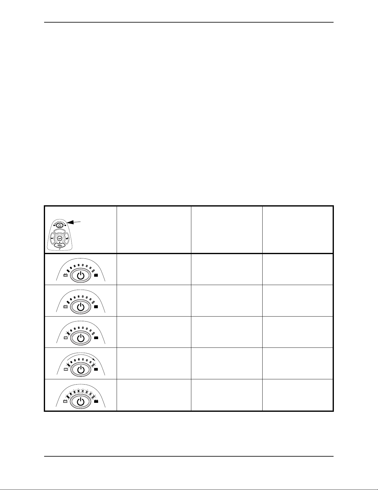
Information Gauge Display Diagnostics
DISPLAY DESCRIPTION DEFINITION COMMENTS
Information
Gauge
Display
All LEDs are off. Power is off.
All LEDs are on. Power is on. Fewer than three LEDs on
implies reduced battery
charge.
Left RED LED is flashing. Battery charge is low. The batteries should be
charged as soon as
possible.
Left to Right “chase”
alternating with steady
display.
All LEDs are flashing slowly. Joystick has detected Out-
Joystick is in
programming, inhibit and/
or charging mode.
of-Neutral-at-Power-Up
mode.
The steady LEDs indicate
the current state of the
battery charge.
Release the joystick back
to Neutral.
Part No 1118377 19 Pronto® M71™
Page 20

SECTION 3—SAFETY INSPECTION/TROUBLESHOOTING
Service Indicator Light Diagnostics
POSSIBLE
ERROR CODE
DESCRIPTION
DIAGNOSTICS CODE
NUMBER OF FLASHES
1 E 01 User Fault 00 Stall Timeout or user error. Release joystick to neutral and try again.
2 E02 Battery Fault 00 Recharge batteries or replace. Check the batteries and cable. Try
3 E03 Left Motor Fault 00 Left Motor Short Circuit Check the left motor, connections and
SUB CODE*
01 Left Motor Open Circuit
02 Left Motor Connection Fault
03 Motor Terminal Connected
04 Left Motor Voltage Fault
DETAILS OF
B-
to B+
ERROR CODE
charging the batteries. Batteries may
require replacing.
motor cable.
SOLUTION
05 Left Motor Bridge Fault
06 Too Many Hardware Current
Limit Events
07 Current Offset Out of Range
08 Hardware Current Limit Fault
4 E04 Right Motor Fault 00 Right Motor Short Circuit Check the right motor, connections and
01 Right Motor Open Circuit
02 Right Motor Connection Fault
B-
03 Motor Terminal Connected
to B+
04 Right Motor Voltage Fault
05 Right Motor Bridge Fault
06 Too Many Hardware Current
Limit Events
07 Current Offset Out of Range
08 Hardware Current Limit Fault
motor cable.
Pronto® M71™ 20 Part No 1118377
Page 21

ERROR CODE
DESCRIPTION
DIAGNOSTICS CODE
NUMBER OF FLASHES
5 E05 Left Park Brake
Fault
6 E06 Right Park Brake
Fault
SECTION 3—SAFETY INSPECTION/TROUBLESHOOTING
POSSIBLE
SUB CODE*
00 Left Park Brake Drive-Time
01 Left Park Brake Output
Enabled When Wheelchair
02 Left Park Brake Output Did
not Enable When Entering
03 Left Park Brake fault during
power-up testing
04 Left park brake feedback low
during drive (park brake
00 Right Park Brake Drive-Time
DETAILS OF
ERROR CODE
Test Failed
Idle
Drive Mode
short)
Test Failed
Check the left park brake connections and
Check the right park brake connections
and cable.
SOLUTION
cable.
01 Right Park Brake Output
Enabled When Wheelchair
Idle
02 Right Park Brake Output Did
not Enable When Entering
Drive Mode
03 Right Park Brake fault during
power-up testing
04 Right park brake feedback
low during drive (park brake
short)
7 E07 Remote Fault 00 Local SR Fault (CPU,
EEPROM, etc.)
01 Joystick fault at the remote
02 Speed pot fault at the remote
Check the communications bus,
connections and wiring. Replace the
remote.
Part No 1118377 21 Pronto® M71™
Page 22

SECTION 3—SAFETY INSPECTION/TROUBLESHOOTING
POSSIBLE
ERROR CODE
DESCRIPTION
DIAGNOSTICS CODE
NUMBER OF FLASHES
8 E08 Controller Fault 00 Controller fault Check connections and wiring. Replace
SUB CODE*
01 RAM fault
02 ROM fault
03 CPU fault
04 EEPROM fault
05 Watchdog fault
06 Stack fault
07 Software fault
08 Power-up testing fault
DETAILS OF
ERROR CODE
power module.
SOLUTION
09 Relay fault or precharge fault
10 Bridge fault or disable all fault
11 Electronics fault: Thermistor
12 Calibration setting fault
9 E09 Communications
Fault
10 E10 General Fault 00 General fault Check all connections and wiring. Contact
11 E11 Incompatible/
incorrect Remote
00 Remote connection lost Check connections and wiring. Replace
01 Low communication mode
00 Incompatible/incorrect
Remote
Invacare Technical Service.
Wrong type of remote connected. Ensure
the branding of the joystick matches that
Bus cable.
of controller unit.
MPJ+, PSR+, PSF+ Joysticks or Displays
SYMPTOM PROBABLE CAUSE SOLUTIONS
SPM L Park Brake Fault or
SPM R Park Brake Fault displays
and wheelchair does not drive.
CHARGER PLUGGED IN displays. Battery charger connected
SPM Battery Fault displays and the
wheelchair does not drive.
JOYSTICK TIMEOUT displays and
the wheelchair does not drive.
Motor lock levers disengaged
(Error code E9 or E10).
(Error code E28).
Batteries need to be charged
(Error code E14).
Joystick or input device is
disconnected (Error code 32).
Engage motor lock levers.
Unplug battery charger from the
wheelchair.
Charge batteries. If batteries fail to
charge properly, check battery charger
or replace batteries. Refer to Replacing
the On-Board Battery Charger on
page 95.
Turn Off power, reconnect the joystick
of input device and turn power On.
Pronto® M71™ 22 Part No 1118377
Page 23

SECTION 3—SAFETY INSPECTION/TROUBLESHOOTING
SYMPTOM PROBABLE CAUSE SOLUTIONS
JS REV TOO LARGE
JS FWD TOO LARGE
JS LFT TOO LARGE or
JS RGT TOO LARGE
displays and the wheelchair does not
drive.
NEUTRAL TESTING displays. The joystick neutral test has
BAD JOYSTICK CAL VALUES
displays and the wheelchair does not
drive.
SPM NOT CONNECTED
SPM Communications Fault
displays and the wheelchair drives
slowly.
ATTENDANT ACTIVE and
displays.
Batteries draw excessive current
when charging.
The joystick or input device is
sending a value outside of the
reverse, forward, left or right
limits (Error codes E01, E02,
E03 or E04).
failed (Error code E18).
The joystick calibration values
are outside of the expected
range (Error code E19).
The MPJ or Display module is
not communicating with the
control module (Error code
E200).
The controller has determined a
fault during a previous turn-off
process (Error code E41).
The Proportional or Digital
Attendant control is active and
can be used to drive the chair
(Error code W05).
Battery failure.
Replace joystick or input device.
Release the joystick and try to get the
joystick back into the center-most
position.
Recalibrate the joystick (joystick throw
procedure).
Check the connections between the
joystick or display and the controller.
Turn the power Off and then back On.
Replace the controller if necessary.
Turn the wheelchair Off and back On.
This is normal behavior.
Have batteries checked for shorted cell.
Replace if necessary.
Electrical malfunction.
Battery indicator flashes the charge
level is low - immediately after
recharge.
Battery indicator flashes the charge
level is low - too soon after being
recharged.
Motor “chatters” or runs irregular. Electrical malfunction. Contact Dealer/Invacare for Service.
Joystick erratic or does not respond
as desired.
Wheelchair does not respond to
commands.
Power indicator Off - even after
recharging.
Battery failure.
Malfunctioning battery charger.
Electrical malfunction.
Batteries not charged.
Weak batteries.
Damaged motor coupling.
Electrical malfunction.
Controller programmed
improperly.
Poor battery terminal
connection.
Electrical malfunction. Contact Dealer/Invacare for Service.
Contact Dealer/Invacare for service.
Check batteries for shorted cell.
Replace if necessary.
Contact Dealer/Invacare for Service.
Contact Dealer/Invacare for Service.
Have charger checked.
Replace batteries if necessary. Contact
Dealer/Invacare for Service.
Contact Dealer/Invacare for Service.
Contact Dealer/Invacare for Service.
Contact Dealer/Invacare to have
controller reprogrammed.
Have terminals cleaned.
Part No 1118377 23 Pronto® M71™
Page 24

SECTION 3—SAFETY INSPECTION/TROUBLESHOOTING
Wheels
SOLUTIONS
FLUTTER
LEFT/RIGHT
WHEELCHAIR VEERS
X X X If pneumatic, check tires for correct and equal pressure.
X X X X Check for loose stem nuts/bolts.
X X Check that casters contact ground at the same time.
SLUGGISH TURN/
CASTERS
PERFORMANCE
RATTLES
SQUEAKS AND
LOOSENESS
IN WHEELCHAIR
WHEELS
WHEELCHAIR 3
Troubleshooting - Common
SYMPTOM PROBABLE CAUSE SOLUTIONS
E28 Error code.
No LED’s on DPJ/
SPJ Joystick
Charger still plugged in when user
tries to drive the wheelchair.
Manual recliner, Power tilt and/or
recline is in reclined position and
drive lockout is engaged
Batteries discharged.
Fuse Open
Loose Battery Terminal
Unplug charger to drive wheelchair.
To disengage drive lockout, return seat to upright
position.
Plug connections back together, and check for
damaged wiring.
Troubleshooting - Motor/Gearbox/Brake
SYMPTOM PROBABLE CAUSE SOLUTIONS
Bad coupler between motor and
Motor makes a
clicking noise.
Grinding noise or
motor is locking up.
Motors stall and
starts up again.
Wheelchair will not
drive with power
on (E09 or E10).
Pronto® M71™ 24 Part No 1118377
gearbox or bad bearings.
Raised commutator plate inside of
motor.
Bad gearbox.
Bad coupler between motor and
gearbox or bad bearings. Bad Gears.
Current Rollback. Stop driving and let electronics cool.
Check motor locks. Engage motor locks to drive wheelchair.
Replace coupler or replace motor.
If bearings are bad, replace motor.
Ohm out motor and replace motor if high reading
is present. Normal reading is 0-5 Ohms.
Replace gearbox or motor.
Replace coupler mor motor.
If bearings are bad, replace motor.
Page 25

SECTION 3—SAFETY INSPECTION/TROUBLESHOOTING
SYMPTOM PROBABLE CAUSE SOLUTIONS
Motor chatters or
runs erratically, or
only one motor
turns.
Wheelchair veers
to the left or right
when driving on
level surface.
E09/E10 error code
will not go away.
Gearbox is leaking
Fluid.
Excessive clicking
coming from
motor/gearbox.
Gearbox shaft
movement or bent
shaft.
Motor Stutters.
Motor Fails to start
after initial installation.
Motor is running
then fails to restart
when stopped.
Damaged connector or worn
brushes.
Bad motor or gearbox
Controller malfunction. Check for error codes with programmer. Refer to
Uneven tire pressure.
Motors out of balance.
Bad motor connection.
Bad brake coil.
Bad seal around drive shaft
Loose hardware.
Bad bearing in motor or gearbox. Replace motor or gearbox.
Loose wheel hardware. Tighten hardware, (use removable Loctite™on
Rough driving. Replace motor or gearbox.
Poor connection or worn brushes. Check motor connectors. Check brushes and
Battery voltage is too low.
Bad Connection
Brake Disengaged
Heavy load on the motors forcing
controller into the current rollback
mode.
Blown fuse in battery wiring
harness.
Damaged Motor Replace brushes if necessary, or replace motor or
Ohm out motors. Check brushes and replace
brushes if necessary. Replace motor or gearbox if
high reading is present. Normal reading is 0-5
Ohms.
electronics manual, part number 1114808.
Inflate tires
Replace tires if worn.
Use programmer to balance motors
Check all connections. Ohm out each brake coil.
Normal reading is 45-50 Ohms.
If seal is bad, replace motor or gearbox. Remove
motor brushes and inspect for grease contamination. Replace motor or gearbox if contamination
is found.
If loose hardware is found retighten hardware.
hardware). Follow torque settings in this manual.
replace if necessary.
Check batteries and recharge if necessary.
Check connector
Engage brake
Leave power ON and allow controller to count
down, and recharge the wheelchair overnight with
power ON.
Replace battery wiring harness.
gearbox if internal damage is determined.
Ohm out motor to check for possible internal
damage (worn out brushes may be possible).
Controller power stage board or
relays may be damaged.
Motor runs but
loses power.
Wheelchair loses all
power while
driving.
Part No 1118377 25 Pronto® M71™
Controller senses heavy load and
has entered the current rollback
mode.
Bad Connection on wheelchair Turn power “OFF”, wait 10 seconds and turn
Replace controller or send to Invacare for repair.
Stop driving and let electronics cool.
power back “ON”.
Check Joystick connection
Check Battery connection and fuses
Page 26

SECTION 3—SAFETY INSPECTION/TROUBLESHOOTING
Troubleshooting - Battery
SYMPTOM PROBABLE CAUSE SOLUTIONS
Batteries won’t
charge.
Short Charge Time
No power to
wheelchair motors.
Corroded battery
wiring connections.
E14 Error code. Low Voltage Recharge or replace battery.
Blown battery fuse or damaged cables.
Batteries sat discharged too long.
One or both batteries may be bad (if
batteries charge up to soon).
Bad connection or blown fuse. Check
Joystick connection.
Batteries are dead.
Loose battery connections Check battery cable connections, may have
Possible water, salt, or urine
damage.
Check cables for damage or replace battery wiring
harness.
Replace batteries
Check each battery and replace if needed.
Check all connections and housings for damage. If
you have blown fuse a new battery wiring harness
must be purchased.
Check battery voltage and replace if necessary.
vibrated loose when driving on rough terrain.
Replace battery wiring harness.
Troubleshooting - Battery Charger
SYMPTOM PROBABLE CAUSE SOLUTIONS
No LED’s on
Charger
Batteries won’t
charge.
Charger not plugged into outlet, or
disconnected from wiring harness on
wheelchair.
No AC power at outlet. Check for AC power with digital volt meter.
Damaged power cord Check for damage on the power cord, replace if
Charger LED’s burnt out Send charger to Invacare for repair.
Charger may have internal fuse that is
blown.
Blown battery fuse in wiring harness,
or charger.
Charger not plugged into outlet. Make sure charger is plugged into the outlet.
No AC power at the outlet. Check for AC power with a digital volt meter.
Charger Power cord may be
damaged, or the connector may be
damaged.
Charger may have internal damage. Charge batteries with known good charger.
Battery voltage too low for charger to
start charging cycle.
Make sure the charger is plugged into the outlet
and check the wiring on the wheelchair.
damaged or send in for repair.
Remove charger cover and check for fuses. if fuses
are present Ohm out fuses and replace if necessary.
Check battery wiring harness fuse on the wheelchair
Check fuse in the charger.
Check for damage and replace if necessary, or
send in for repair.
Replace batteries.
Pronto® M71™ 26 Part No 1118377
Page 27

SECTION 3—SAFETY INSPECTION/TROUBLESHOOTING
SYMPTOM PROBABLE CAUSE SOLUTIONS
Batteries have
short driving range
during a single
charge. Battery
Gauge falls off
faster than normal.
E28 Error code.
Consumer not charging batteries long
enough.
Batteries may be weak. Perform load test or check “Battery Quality Menu”
Check programming settings. Torque setting and power level setting may be too
Heavy load on motors. Chairs weight distribution may be offset (wheel-
Charger still plugged in when user tries
to drive the wheelchair.
Instruct consumer to charge for 8-10 hours minimum.
with the programmer. Refer to MK
manual, part number 1114808.
high. Refer to MK
ber 1114808.
chair may be front loaded).
Unplug charger to drive wheelchair.
electronics manual, part num-
5
electronics
5
Checking Battery Charge Level
The following “Do’s” and “Don’ts” are provided for your convenience and safety.
DO DON’T
Read and understand this manual and any service
information that accompanies a battery and charger
before operating the wheelchair.
Move the wheelchair to a work area before opening
battery box or installing service batteries.
Recharge as frequently as possible to maintain a high
charge level and extend battery life.
Follow recommendations in this manual when selecting a battery or charger.
Fully charge new batteries before using. Don’t put new batteries into servcie before charging.
Use a carrying strap to remove, move or install a battery.
Push battery clamps on the terminals. Spread clamps
wider if necessary.
Use ONLY a GEL charger for a GEL battery or
“Sealed” battery.
Don’t perform any installation or maintenance without
first reading this manual.
Don’t perform installation or maintenance of batteries
in an area that could be damaged by battery spills.
Don’t make it a habit to discharge batteries to the lowest level.
Don’t use randomly chosen batteries or chargers.
Don’t tip or tilt batteries.
Don’t tap on clamps and terminals with tools.
Don’t mismatch your battery and chargers.
Part No 1118377 27 Pronto® M71™
Page 28

SECTION 3—SAFETY INSPECTION/TROUBLESHOOTING
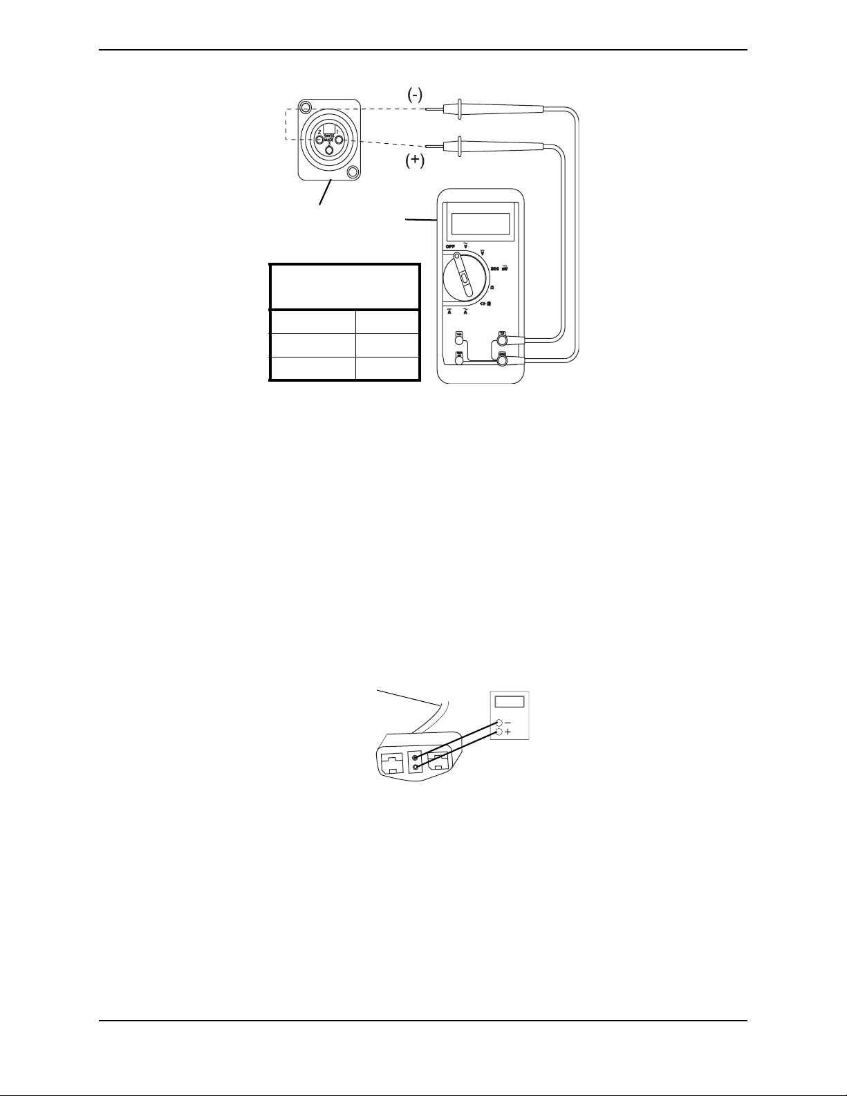
Field Load Test
NOTE: For this procedure, refer to FIGURE 3.1 on page 29.
NOTE: The following test can also be performed through the controller of the wheelchair along
with a remote programmer. Refer to the electronics manual, part number 1114808 supplied with
each wheelchair.
Old batteries lose their ability to store and release power, due to increased internal
resistance. This means that as you try to take power from the battery, some of that power
is used up in the process of passing through the battery, resulting in less voltage at the
posts. The more power drawn, the lower the voltage available. When this lost voltage
drops the output 1.0 volts under load (2.0 for a pair), replace the batteries.
To spot this problem, test batteries under load.
Use a digital voltmeter to check battery charge level at the charger connector. It is located
on the joystick.
NOTE: READ these instructions CAREFULLY and the manufacturer’s instructions on the
digital voltmeter before using the digital voltmeter.
NOTE: Invacare recommends that ONLY a qualified technician perform this test.
1. Ensure that power is OFF.
2. Make sure battery is fully charged. An extremely discharged battery will exhibit the
same symptoms as a bad one.
3. Remove the footrests from the wheelchair
4. Connect the voltmeter leads to the charger port on the wheelchair as shown in
FIGURE 3.1. Most digital voltmeters are not affected by polarity, however, analog
meters (meters with swinging needles) can be and should be used carefully. A good
meter reading should be 25.5 to 26 VDC.
WARNING
When performing STEPS 5 and 6 ensure feet are clear from casters and wall
otherwise injury may result
5. Sit in wheelchair and place feet against a wall, workbench or other stationary object.
6. Turn the power ON and carefully push the joystick forward, trying to drive the
wheelchair through the stationary object.
NOTE: This puts a heavy load on the batteries as they try to push through the stationary object. If
the wheels spin, have two individuals (one on each arm) apply as much downward pressure as
possible on the arms of the wheelchair.
7. Read the meter while the motors are straining, no longer than 3-4 seconds, to
determine the voltage under load.
NOTE: If the voltage drops more than 2 volts from a pair of fully charged batteries while under
load, they should be replaced regardless of the unloaded voltages.
Pronto® M71™ 28 Part No 1118377
Page 29
SECTION 3—SAFETY INSPECTION/TROUBLESHOOTING
Charge
r Port
Digital
Voltmeter
BATTERY
QUALITY
0 to 2 volts Good
2 to 2.5 volts Poor
2.5 or more Bad
FIGURE 3.1 Field Load Test
Motor Testing
NOTE: For this procedure, refer to FIGURE 3.2.
1. On the 4-pin motor connector, locate the two contacts in the red and black housings.
2. Set the digital multimeter to measure ohms (Ω).
3. Measure the resistance between the two motor contacts.
NOTE: A normal reading is between .5 to 5 ohms. A reading of O.L. (open line) or in excess of 15
ohms indicates a problem. High readings are generally caused by bad connections and/or damaged
brushes. Contact Invacare.
To Motor
4 Pin Motor
Connector
FIGURE 3.2 Motor Testing
Part No 1118377 29 Pronto® M71™
Page 30

SECTION 4—SEAT ASSEMBLY
SECTION 4—SEAT ASSEMBLY
WARNING
After ANY adjustments, repair or service and BEFORE use, make sure all attaching
hardware is tightened securely - otherwise injury or damage may result.
Before performing any maintenance, adjustment or service verify that ON/OFF
switch on the joystick is in the OFF position.
Removing/Installing the Seat Assembly
WARNING
For wheelchairs with POWER TILT ONLY or PTO PLUS, it is unnecessary to
remove the seat. Refer to the owner’s manual for information on tilting the seat.
NOTE: For this procedure, refer to FIGURE 4.1 on page 31.
NOTE: This procedure applies to ASBA and van seat assemblies.
Removing Seat
1. Disconnect the joystick cable at rear of seat. Refer to Disconnecting/Connecting the
Joystick on page 97.
2. Push down on the latch bar underneath front of seat (Detail “A” of FIGURE 4.1).
3. Rotate seat assembly backward (Detail “B” of FIGURE 4.1).
4. Slide the seat assembly forward to disengage seat from the pivot brackets located in
the rear of the wheelchair.
Installing Seat
1. Position the seat in the rear pivot brackets (Detail “B” of FIGURE 4.1).
2. Rotate seat assembly forward.
3. When seat is lowered, engage seat brackets into seat clevis pins.
WARNING
When reinstalling the seat verify that the seat brackets are engaged with the seat
clevis pins by pulling up on the latch bar - otherwise injury or damage may result.
4. Pull up on latch bar to verify that seat brackets are engaged with seat clevis pins.
Pronto® M71™ 30 Part No 1118377
Page 31

Joystick
Connector
Seat
Latch Bar is
located under the
front of the seat
SECTION 4—SEAT ASSEMBLY
DETAIL “B”DETAIL “A”
Seat Seat
Seat
Brackets
Rear Pivot
Brackets
Seat
Clevis
Pins
FIGURE 4.1 Removing/Installing the Seat Assembly
Adjusting the Seat Height
WARNING
For wheelchairs with POWER TILT ONLY, refer to ADJUSTING SEAT HEIGHT in
SECTION 4 of the Power Tilt Only for Pronto M71 and M91 owner’s manual, Part
Number 1118362.
PTO PLUS ONLY - DO NOT adjust the seat height. Adjusting the seat height from
the factory setting will make the wheelchair unstable and injury or damage may
occur. The M71 wheelchair seat should only be mounted in mounting hole B
(FIGURE 4.2).
For users over 250 lbs: The seat MUST be mounted in the furthest rearward
position and the front seat posts MUST be in the 1-inch raised position or lower
mounting holes A or B. Refer to Table: Available Mounting Holes
available mounting positions.
DO NOT adjust the rear seat posts higher than the front seat posts.
on page 32 for
NOTE: For this procedure, refer to FIGURE 4.2 on page 32.
NOTE: The seat can be adjusted to five height positions in 1/2-inch increments.
1. Remove the seat assembly. Refer to Removing/Installing the Seat Assembly
on
page 30.
Part No 1118377 31 Pronto® M71™
Page 32

SECTION 4—SEAT ASSEMBLY
2. Remove the mounting screw and locknut that secure the adjustable height tube to the
support tube.
3. Adjust tube to desired mounting position. Refer to Table: Available Mounting Holes
on page 32 for available mounting positions.
4. Reinstall mounting screw and locknut. Securely tighten.
5. Repeat STEPS 2-4 for the three remaining adjustable height tubes.
6. Reinstall the seat assembly. Refer to Removing/Installing the Seat Assembly
page 30.
Mounting
Hole
A
B
C
D
E
Support Tube
Rear Adjustable
Height Tube
Locknut
Support Tube
Front Adjustable
Height Tube
Mounting
Mounting Screw
FIGURE 4.2 Adjusting the Seat Height
AVAILABLE MOUNTING HOLES
WHEELCHAIR EQUIPPED WITH: AVAILABLE MOUNTING HOLES FOR
FRONT ADJUSTABLE HEIGHT TUBE
on
Hole
A
B
C
D
E
VAN SEAT WITH NON-HEMI FRONT RIGGING A B C D E
Rear Adjustable Height Tube
Mounted in hole A N/A** N/A** N/A** N/A** N/A**
Mounted in hole B N/A** N/A** N/A** N/A** N/A**
Mounted in hole C N/A** N/A** N/A** N/A**
Mounted in hole D N/A** N/A** N/A** N/A**
Mounted in hole E N/A** N/A** N/A** N/A**
VAN SEAT WITH HEMI FRONT RIGGING OR
FOOTBOARD
ABCDE
Rear Adjustable Height Tube
Mounted in hole A
Mounted in hole B N/A*
Mounted in hole C N/A* N/A*
Mounted in hole D N/A* N/A* N/A*
Mounted in hole E N/A* N/A* N/A* N/A*
Pronto® M71™ 32 Part No 1118377
Page 33

SECTION 4—SEAT ASSEMBLY
WHEELCHAIR EQUIPPED WITH: AVAILABLE MOUNTING HOLES FOR
FRONT ADJUSTABLE HEIGHT TUBE
ASBA SEAT WITH FOOTBOARD
OR FRONT RIGGINGS (NON-HEMI OR HEMI)
ABCDE
Rear Adjustable Height Tube
Mounted in hole A N/A** N/A** N/A** N/A** N/A**
Mounted in hole B N/A*
Mounted in hole C N/A* N/A*
Mounted in hole D N/A* N/A* N/A*
Mounted in hole E N/A* N/A* N/A* N/A*
*NOTE: This mounting hole combination would result in a forward seat dump (the rear of the seat
is higher than the front of the seat). The seat should never be adjusted to a position that results in
a forward seat dump.
**NOTE: This mounting hole combination will cause interference between the front riggings and/
or the ASBA seat frame and wheelchair base. DO NOT use this mounting hole combination.
Removing/Installing the Adjustable Height Tubes
NOTE: For this procedure, refer to FIGURE 4.3.
NOTE: Reverse this procedure to install the adjustable height tubes.
1. Remove the seat assembly. Refer to Removing/Installing the Seat Assembly on
page 30.
2. Remove the desired side shroud from the wheelchair. Refer to Removing/Installing
the Shrouds on page 74.
3. Remove the mounting screw and locknut securing the front adjustable height tube to
the front support tube.
4. Remove the front adjustable height tube from the front support tube.
5. Remove the mounting screw and locknut securing the rear adjustable height tube to
the rear support tube.
Part No 1118377 33 Pronto® M71™
Page 34

SECTION 4—SEAT ASSEMBLY
6. Remove the rear adjustable height tube from the rear support tube.
Rear Adjustable Height Tube
Rear Support Tube
Mounting Screw
Front Support Tube
Locknut
Locknut
Front Adjustable
Height Tube
Mounting Screw
FIGURE 4.3 Removing/Installing the Adjustable Height Tubes
Pronto® M71™ 34 Part No 1118377
Page 35

SECTION 4—SEAT ASSEMBLY
Adjustable ASBA Seat Service Procedures
Removing/Installing the Seat Pan
NOTE: For this procedure, refer to FIGURE 4.4.
Removing
1. Remove the seat cushion.
2. Remove the two socket screws securing
the seat pan to the seat frame.
Seat
Pan
Socket
Screw
3. Remove the seat pan from the seat
frame.
Installing
1. Position the new seat pan onto the seat
frame as shown.
2. Secure the new seat pan to the seat
frame using the two socket screws.
Seat
Frame
3. Install the seat cushion.
FIGURE 4.4 Removing/Installing the Seat
Pan
Adjusting the Seat Width
NOTE: For this procedure, refer to FIGURE 4.5 on page 36.
NOTE: The seat width can be adjusted from 16 to 20 inches.
NOTE: The spreader bar must be replaced for seating systems ordered with the BPO (Back Post
Only) option.
1. If necessary, remove the spreader bar. Refer to Removing/Installing the Spreader Bar
on page 43.
2. Remove the hex screw and coved washers securing each crossbar to the seat frame.
3. Pull/push the side rails to the desired width shown in the following table.
Seat Width Mounting Holes
SEAT
SIDE RAIL MOUNTING HOLES*
WIDTH
16-INCH
17-INCH
*NOTE: Only right side rail shown. Use the same mounting hole for opposite side rail.
Part No 1118377 35 Pronto® M71™
Page 36

SECTION 4—SEAT ASSEMBLY
Seat Width Mounting Holes
SEAT
SIDE RAIL MOUNTING HOLES*
WIDTH
18-INCH
19-INCH
20-INCH
*NOTE: Only right side rail shown. Use the same mounting hole for opposite side rail.
4. Align the crossbar mounting holes with the seat frame mounting holes.
5. Secure each crossbar to the seat frame with a hex screw and coved washer. Torque the
hex screw to 75 in-lbs.
6. If necessary, install the new spreader bar. Refer to Removing/Installing the Spreader
Bar on page 43.
NOTE: Seat pan, back and
arms removed for clarity.
Crossbar
Crossbar
Seat Frame
Hex Screw
Side Rail
Mounting Holes
Seat Frame
Mounting
Hole
Coved
Washer
FIGURE 4.5 Adjusting the Seat Width
Adjusting the Seat Depth
NOTE: For this procedure, refer to FIGURE 4.6 on page 38.
1. Examine the following chart to determine if the desired seat depth adjustment is
within or beyond the range of the existing seat frame.
FRAME SIZE SEAT DEPTH RANGE
SMALL 16 - 19 inches in 1-inch increments
Pronto® M71™ 36 Part No 1118377
Page 37

SECTION 4—SEAT ASSEMBLY
FRAME SIZE SEAT DEPTH RANGE
LARGE 19 - 20 inches in 1-inch increments
2. Perform one of the following:
• Seat Depth Adjustment is WITHIN the Range of Existing Seat Frame - Proceed to
STEP 3.
• Seat Depth Adjustment is BEYOND the Range of Existing Seat Frame - Replace the
side rails. Refer to Removing/Installing Side Rails on page 38.
3. Loosen, but DO NOT remove, the four hex screws and washers securing the bottom
of the cane brackets to the side rails.
4. Loosen, but DO NOT remove, the four hex screws securing the front arm sockets to
the side rails.
5. Use the following Seat Depth Adjustment Table to determine the distance required to
obtain the desired seat depth.
Seat Depth Adjustment Table
SEAT DEPTH DISTANCE* (IN INCHES)
16-INCH 5.50
17-INCH 4.50
18-INCH 3.50
19-INCH 2.50 (Small Frame)
5.50 (Large Frame)
20-INCH 4.50
*NOTE: Distance is between the rear of the rear arm socket and the rear of the side rail (Detail “A”).
6. Measure the distance determined in STEP 5 from the end of the side rail.
7. Slide the cane brackets along the side rails to align the rear of the rear arm socket with
the distance measured in STEP 6.
8. Secure the cane brackets to the side rails with the four hex screws and washers. Torque
the hex screws to 13 ft-lbs.
9. Secure the front arm sockets to the side rails with the four hex screws. Torque the hex
screws to 13 ft-lbs.
Part No 1118377 37 Pronto® M71™
Page 38

SECTION 4—SEAT ASSEMBLY
Cane
Bracket
Side Rail
DETAIL “A” - SEAT
DEPTH
MEASUREMENT
Rear
Arm
Socket
Side Rail
Measure Distance
Front
Arm
Socket
Hex Screws
FIGURE 4.6 Adjusting the Seat Depth
Removing/Installing Side Rails
NOTE: For this procedure, refer to FIGURE 4.7 on page 39.
Removing Side Rails
1. Remove both armrests.
2. Remove the two hex screws, washer and lanyard securing the crossbars to the side rail.
3. Loosen, but DO NOT remove, the four hex screws securing the cane brackets to the
side rails.
4. Loosen, but DO NOT remove, the four hex screws securing the front arm sockets to
the side rails.
5. Use a screwdriver to gently tap the two roll pins out of the side rails.
6. Slide both cane brackets (with T-nuts and back canes) out of the slots in the side rails.
7. Slide both front arm sockets (with T-nuts) out of the slots in the side rails.
Pronto® M71™ 38 Part No 1118377
Page 39

SECTION 4—SEAT ASSEMBLY
8. Pull both side rails off the crossbars.
Installing Side Rails
1. Install new side rails onto crossbars.
NOTE: Ensure long end of side rail is towards the front of the wheelchair.
2. Secure the side rails to the crossbars with the hex screws, washer and lanyard. Torque
to 75 in-lbs.
3. Slide cane brackets (with T-nuts and back assembly) into the slots in the side rails.
4. Slide front arm sockets (with T-nuts) into the slots in the side rails.
5. Use a rubber mallet to tap the two roll pins into the side rails.
6. Tighten the four hex screws to secure the cane brackets to the side rails. Torque to 13
ft-lbs.
7. Install the armrests.
NOTE: It may be necessary to slide the front arm sockets to the proper position to install the
armrests.
8. Tighten the four hex screws to secure the front arm sockets to the side rails. Torque to
13 ft-lbs.
Roll
Pin
Back
Cane
Side Rail
Washer
Crossbar
Side View
Cane Bracket
Slot
Hex Screws
Front Arm
Socket
Hex Screws
FIGURE 4.7 Removing/Installing Side Rails
Part No 1118377 39 Pronto® M71™
Page 40

SECTION 4—SEAT ASSEMBLY
Replacing the Seat Frame
NOTE: For this procedure, refer to FIGURE 4.13.
1. Remove the front riggings from the seat frame. Refer to Installing/Removing Front
Riggings on page 66.
2. Remove the seat from the wheelchair. Refer to Removing/Installing the Seat Assembly
on page 30.
3. Remove the seat pan. Refer to Removing/Installing the Seat Pan on page 35.
4. Remove the four mounting screws and locknuts securing the seat frame to the seat
frame adapter.
5. Remove the seat frame from the seat frame adapter.
6. Discard the existing seat frame.
7. Align the four mounting holes of the new seat frame with the correct mounting
position on the seat frame adapter (DETAIL “A” of FIGURE 4.13).
8. Using four existing mounting screws and four new locknuts, secure the seat frame to
the seat frame adapter.
9. Install the seat pan. Refer to Removing/Installing the Seat Pan on page 35.
10. Install the seat onto the wheelchair. Refer to Removing/Installing the Seat Assembly
on page 30.
Mounting Screws
Seat
Frame
Adapter
Locknuts
Mounting Screws
Seat
Frame
Locknuts
16 Inch
17 Inch
18 Inch
19 Inch
20 Inch
16 Inch
17 Inch
18 Inch
19 Inch
20 Inch
NOTE: Measurements given according to
DETAIL “A” - SEAT FRAME
MOUNTING POSITIONS
Front of Seat Frame
Adapter
Rear of Seat Frame
Adapter
seat frame depth.
FIGURE 4.8 Replacing the Seat Frame
Pronto® M71™ 40 Part No 1118377
Page 41

SECTION 4—SEAT ASSEMBLY
Removing/Installing the Back Canes
NOTE: For this procedure, refer to FIGURE 4.9 on page 42.
NOTE: Existing hardware will be reused.
NOTE: Take note of position and orientation of mounting hardware for reinstallation.
Removing
1. Remove armrest from the wheelchair. Refer to the wheelchair owner’s manual.
NOTE: Note the back angle before disassembly for proper reinstallation.
2. For proper installation, note the mounting position of the upper hex screw securing
the cane bracket to the back cane.
3. Remove the upper hex screw, washer and locknut securing the cane bracket to the
back cane.
4. Remove the lower hex screw, washer and locknut securing the cane bracket to the back
cane.
5. Remove the back cane from the wheelchair.
6. Repeat STEPS 1 - 6 for the opposite back cane.
Installing
NOTE: If replacing back canes, discard existing back canes and perform this procedure using new
back canes.
1. Install the lower hex screw, washer and locknut through the slot in the cane bracket to
secure the cane bracket to the back cane.
NOTE: The cane bracket should be positioned as shown in FIGURE 4.9.
2. Install the upper hex screw, washer and locknut through one of the following:
• Using the Same Back Angle - the mounting hole noted in STEP 3 of Removing
on
page 41.
• Changing the Back Angle - the mounting hole determined in Adjusting the Back
Angle on page 43.
3. Torque both locknuts to 13 ft-lbs.
4. Repeat STEPS 1 - 3 for the opposite back cane.
5. Reinstall the flip back armrest onto the wheelchair. Refer to the wheelchair owner’s
manual.
Part No 1118377 41 Pronto® M71™
Page 42

SECTION 4—SEAT ASSEMBLY
Back Cane
Cane Bracket
Upper Hex Screw
Washers
Locknuts
Lower Hex Screw
Slot
FIGURE 4.9 Removing/Installing the Back Canes
Replacing Seat Positioning Strap
NOTE: For this procedure, refer to FIGURE 4.10.
1. Remove the seat cushion from the seat pan.
2. Move the flip back armrests out of the way. Refer to Adjusting Flip Back Armrests on
page 60.
3. Remove the two mounting screws, locknuts, washers and quick-release pin tabs that
secure the seat positioning straps to the seat frame.
4. Remove the two halves of the seat positioning strap from the rear seat frame.
5. Reposition the two new seat positioning strap inside of the seat frame as shown.
6. Reinstall the two mounting screws and quick-release pin tabs that secure the seat
positioning straps to the seat frame and torque to 75 in-lbs.
7. Reinstall the seat cushion onto the seat pan.
Mounting
Holes
Mounting Screw
Seat Frame
Quick-Release Pin Tab
Seat Frame
Mounting Screw
Quick-Release Pin Tab
Locknuts
Washers
Seat Positioning Strap Halves
FIGURE 4.10 Replacing Seat Positioning Strap
Pronto® M71™ 42 Part No 1118377
Page 43

SECTION 4—SEAT ASSEMBLY
Adjusting the Back Angle
WARNING
Wheelchairs with TRRO Only - Adjusting the back angle from the factory setting
will void TRRO compliance. After adjusting the back angle, DO NOT transport an
occupied wheelchair in a motor vehicle of any kind. The wheelchair may only be
transported in a motor vehicle while unoccupied, and will be considered TRBKTS.
NOTE: For this procedure, refer to FIGURE 4.11.
1. Loosen, but DO NOT remove, the two lower hex screws securing the cane brackets to
the back canes.
2. Remove the two upper hex screws, washers and locknuts securing the cane brackets
to the back canes.
3. Align the upper mounting holes in the back canes with the desired mounting holes in
the cane brackets (Detail “A”).
4. Install the two upper hex screws, washers and locknuts to secure the cane brackets to
the back canes.
5. Torque the locknuts to 13 ft-lbs.
DETAIL “A” - CANE
BRACKET MOUNTING
HOLES
95°
105°
100°
85°
90°
FIGURE 4.11 Adjusting the Back Angle
Back Cane
Locknut
Cane Bracket
Washer
Upper Hex
Screw
Lower Hex
Screw
Part No 1118377 43 Pronto® M71™
Page 44

SECTION 4—SEAT ASSEMBLY
ASBA Seat Service Procedures
Removing/Installing the Seat Pan
NOTE: For this procedure, refer to FIGURE 4.12.
NOTE: Take note of the position and orientation of the mounting hardware, seat positioning straps
and quick release pin tabs for installing of the seat pan.
NOTE: Reverse this procedure to install the seat pan. Torque locknuts to 75-inch-lbs.
1. Perform one of the following:
A. Remove seating system. Refer to manufacturers seating system installation
instructions.
B. Remove cushion by pulling up to release hook and loop strips. Remove cushion
from seat pan.
2. Remove the two rear mounting screws, quick release pin tabs, spacers and locknuts
that secure the seat pan and seat positioning straps to the seat frame.
NOTE: The two front mounting screws, spacers and locknuts also secure the front rigging support
tubes to the seat frame.
3. Remove the four mounting screws, locknuts and four spacers securing the seat pan to
the seat frame (FIGURE 4.12).
4. Remove the seat pan from the seat frame.
Mounting Screws
Seat
Positioning
Strap
Tab
Seat Pan
Seat Frame
Spacer
Locknut
Quick Release Pin
Locknut
FIGURE 4.12 Removing/Installing the Seat Pan
Pronto® M71™ 44 Part No 1118377
Page 45

SECTION 4—SEAT ASSEMBLY
Changing the Seat Width/Depth
NOTE: The seat frame width and depth are not adjustable. A new seat frame must be ordered to
change seat depth and/or width. Refer to Replacing the Seat Frame on page 45.
Replacing the Seat Frame
NOTE: For this procedure, refer to FIGURE 4.13.
1. Remove the front riggings from the seat frame. Refer to Installing/Removing Front
Riggings on page 66.
2. Remove the seat from the wheelchair. Refer to Removing/Installing the Seat Assembly
on page 30.
3. Remove the seat pan. Refer to Removing/Installing the Seat Pan on page 44.
4. Remove the four mounting screws and locknuts securing the seat frame to the seat
frame adapter.
5. Remove the seat frame from the seat frame adapter.
6. Discard the existing seat frame.
7. Align the four mounting holes of the new seat frame with the correct mounting
position on the seat frame adapter (DETAIL “A” of FIGURE 4.13).
8. Using four existing mounting screws and four new locknuts, secure the seat frame to
the seat frame adapter.
9. Install the seat pan. Refer to Removing/Installing the Seat Pan on page 44.
10. Install the seat onto the wheelchair. Refer to Removing/Installing the Seat Assembly
on page 30.
Mounting Screws
Seat
Frame
Adapter
Mounting Screws
Seat
Frame
Locknuts
16 Inch
17 Inch
18 Inch
19 Inch
20 Inch
21 and 22 Inch
16 Inch
17 Inch
18 Inch
19 Inch
20 Inch
21 and 22 Inch
DETAIL “A” - SEAT FRAME
MOUNTING POSITIONS
Front of Seat Frame
Adapter
Rear of Seat Frame
Adapter
Locknuts
NOTE: Measurements given according to
seat frame depth.
FIGURE 4.13 Replacing the Seat Frame
Part No 1118377 45 Pronto® M71™
Page 46

SECTION 4—SEAT ASSEMBLY
Replacing the Seat Positioning Strap
NOTE: For this procedure, refer to FIGURE 4.14.
1. Remove the seat cushion from the seat pan.
2. Remove the flip back armrests. Refer to Removing/Installing Flip Back Armrest on
page 58.
3. Remove the two mounting screws, quick release pin tabs, spacers and locknuts that
secure the seat pan and seat positioning straps to the seat frame.
4. Remove the two halves of the seat
positioning strap from the rear seat
Mounting Screws
Seat Pan
frame.
5. Reposition the two new seat
positioning strap halves underneath
Seat
Positioning
Strap
seat rails.
6. Reinstall the two mounting screws,
quick release pin tabs, spacers and
locknuts that secure the seat pan and
seat positioning straps to the seat frame
and torque to 75 inch-lbs.
7. Reinstall the seat cushion onto the seat
pan.
Tab
Locknut
Seat Frame
Quick Release Pin
FIGURE 4.14 Replacing the Seat
Positioning Strap
Removing/Installing the Back Upholstery
NOTE: The back canes must be removed when removing/installing the back upholstery. Refer to
Removing/Installing/Changing the Back Cane Height on page 46.
Removing/Installing/Changing the Back Cane Height
NOTE: For this procedure, refer to FIGURE 4.15 on page 49.
NOTE: If changing the back height, new back upholstery may be needed as well. Refer to the
following chart to determine if new back upholstery is needed:
NOTE BACK UPHOLSTERY
HEIGHT
If back height required is within the range of the original back upholstery
height, only new back canes will be needed.
If the back height required is NOT within the range of the original back upholstery height, new back upholstery, and back canes will be required
NOTE: Existing hardware and inserts will be reused.
NOTE: Take note of position and orientation of mounting hardware for reinstallation.
Pronto® M71™ 46 Part No 1118377
16 to 17 inches
18 to 19 Inches
20 inches
21 to 22 inches
Page 47

SECTION 4—SEAT ASSEMBLY
Removing
1. Remove flip back armrest from the wheelchair. Refer to Arm Service Procedures for
ASBA or Adjustable ASBA Seat on page 58.
NOTE: Note the back angle before disassembly for proper reinstallation.
2. On the side of wheelchair with armrest removed, remove one of the mounting screws,
washer, coved washer and locknut that secures the back cane to the seat frame.
3. Cut the tie-wraps that secure the bottom of the existing back upholstery to the seat
frame.
4. Thread the mounting screw removed in STEP 2 through the back cane from the inside
of the wheelchair to hold the insert in place.
5. Remove the remaining mounting screw, washer, coved washer and locknut that
secures the back cane to the seat frame.
6. Repeat STEPS 1-4 for the opposite side of the wheelchair and remove back assembly
from wheelchair.
7. Remove the two mounting screws and washers that secure the existing back
upholstery to the back canes.
8. If present, release hook and loop strap securing the back upholstery to the back canes.
9. Remove the two mounting screws used to keep inserts in the back canes in STEP 3. Set
mounting screws and inserts aside.
10. Loosen, but DO NOT remove, the two mounting screws and locknuts securing the
spreader bar to the back canes.
11. Grasp the hand grip and slide the back cane out of the spreader bar (if applicable) and
the back upholstery.
Installing
NOTE: If replacing back upholstery, discard existing back upholstery and perform this procedure
using new back upholstery.
NOTE: If replacing back canes, discard existing back canes and perform this procedure using new
back canes.
NOTE: Spreader bar is required on ALL back heights between 20-24-inches. Spreader bar is
required on back heights 16, 17, 18, or 19 ONLY if the width or depth of the chair exceeds 19 inches.
Refer to FIGURE 4.15 for proper spreader bar location on back canes.
1. Slide one back cane into back upholstery and through spreader bar (if applicable).
2. Position insert into bottom of back cane.
3. From inside of wheelchair, thread a mounting screw through the back cane to hold the
insert in position when installing the back assembly.
4. Repeat STEPS 1-3 for remaining back cane.
NOTE: If changing the back angle, refer to Adjusting the Back Angle on page 50 to determine the
proper mounting holes for the desired back angle.
Part No 1118377 47 Pronto® M71™
Page 48

SECTION 4—SEAT ASSEMBLY
5. Position back assembly between the back angle plates (FIGURE 4.15).
6. On one side of wheelchair, align back cane mounting holes with the desired mounting
holes of the back angle plate.
7. Remove the two mounting screws used to keep inserts in the back canes in STEP 3. Set
mounting screws and inserts aside.
WARNING
The back canes MUST be fastened securely to the seat frame BEFORE using the
wheelchair. Torque to 75-inch-lbs.
8. From outside of wheelchair, secure the back cane to the back angle plate using two
mounting screws, washers, coved washers and locknuts (FIGURE 4.15). Use Loctite
242 and torque to 75-inch-lbs.
9. Repeat STEPS 6-8 on opposite side of wheelchair.
10. Secure the top of the back upholstery to the back canes with the two existing mounting
screws.
11. Using two new tie-wraps, secure bottom of back upholstery to the seat frame.
12. If necessary, reposition the spreader bar at the correct height for the corresponding
back height and torque the mounting hardware to 60-inch-lbs (FIGURE 4.15).
13. If present, secure back upholstery hook and loop straps around back canes.
14. Reinstall the flip back armrest onto the wheelchair. Refer to Removing/Installing Flip
Back Armrest on page 58.
Pronto® M71™ 48 Part No 1118377
Page 49

SECTION 4—SEAT ASSEMBLY
Back Canes
Screws with
Washers
Back Upholstery
Coved
Washers
Locknuts
NOTE: When replacing the back upholstery,
back assembly or changing back height, follow
these guidelines for spreader bar height:
BACK HEIGHT 0SPREADER BAR
HEIGHT
16-inches 5-inches
17-inches 5-inches
18-19-inches 7-inches
20-22-inches 7-inches
NOTE: Height of Spreader Bar from Bottom
of Back Canes to Top of Spreader Bar Clamp.
Spreader Bar
Locknut
Back Insert
Back Angle Plate
Mounting Holes
Screw with Lug
Mounting Screws
Washers
Seat Frame
FIGURE 4.15 Removing/Installing the Back Upholstery
Part No 1118377 49 Pronto® M71™
Page 50

SECTION 4—SEAT ASSEMBLY
Adjusting the Back Angle
NOTE: For this procedure, refer to FIGURE 4.16.
1. Remove the flip back armrests from the wheelchair. Refer to Removing/Installing Flip
Back Armrest on page 58.
2. Remove the mounting screw, washer, coved washer and locknut from the top
mounting hole of back angle plate and back cane (FIGURE 4.16).
NOTE: To avoid losing the insert in each back cane, thread the mounting screw through the cane
from the inside of wheelchair to hold the insert in place.
3. Remove the mounting screw, washer, coved washer and locknut from the bottom
mounting hole of the back angle plate and back cane.
4. Reposition the back canes into the correct mounting holes of the back angle plate to
obtain a back angle between 80° and 100° in 5° increments.
5. Starting with the bottom mounting hole, use the two mounting screws, washers,
coved washers and locknuts to secure the back cane with insert to the back angle plate.
6. Torque mounting screws to 75-inch-lbs.
7. Reinstall the flip back armrests onto the wheelchair. Refer to Removing/Installing Flip
Back Armrest on page 58.
ANGLE BACK CANE MOUNTING HOLE BACK ANGLE PLATE HOLE
Top Front
Bottom Rear
Back Angle
Plate
Top Front
Bottom Center
Back Angle
Plate
Top Front
Bottom Front
Back Angle
Plate
Top Center
Bottom Front
Back Angle
Plate
80°
85°
90
95°
Top
Bottom
Top
2nd From
Bottom
Top
O
Bottom
Top
2nd From
Bottom
Back
Cane
Back
Cane
Back
Cane
Back
Cane
Top
100°
Bottom
Back
Cane
Top Rear
Bottom Front
Back Angle
Plate
FIGURE 4.16 Adjusting the Back Angle
Pronto® M71™ 50 Part No 1118377
Page 51

Van Seat Service Procedures
Adjusting the Back Angle
NOTE: For this procedure, refer to
FIGURE 4.17.
1. Lift up on the release handle and adjust
back to desired angle.
2. Let go of the release handle to lock the
back in position.
Adjusting the Seat Position on Van Seat Frame
Back
Release
Handle
FIGURE 4.17 Adjusting the Back Angle
SECTION 4—SEAT ASSEMBLY
WARNING
For users over 250 lbs: The seat MUST be mounted in the furthest rearward
position and the front seat posts MUST be in the 1-inch raised position or lower
mounting holes A or B. Refer to Table: Available Mounting Holes on page 32 for
available mounting positions
DO NOT adjust the rear seat posts higher than the front seat posts.
NOTE: For this procedure, refer to FIGURE 4.18 on page 52.
1. Remove the seat assembly. Refer to Removing/Installing the Seat Assembly on
page 30.
2. Remove the four bolts, four coved washers and two spacers securing the van seat to
the seat frame.
3. Separate van seat from seat frame.
4. Refer to FIGURE 4.18 to determine the correct mounting holes to achieve the desired
seat position on the seat frame.
5. Align the van seat mounting holes determined in STEP 4 with the seat frame mounting
holes.
6. Secure the van seat to the seat frame using the four bolts, four coved washers and two
spacers. Securely tighten.
7. Reinstall the seat assembly. Refer to Removing/Installing the Seat Assembly
page 30.
Part No 1118377 51 Pronto® M71™
on
Page 52

SECTION 4—SEAT ASSEMBLY
Spacer
Van Seat
Coved Washer
Mounting Hole (Seat Frame)
Coved Washer
1-inch Back
Standard Seat Position
2-inch Forward
1-inch Back
Front of seat
These
mounting
holes are
not used
Seat Frame
Bolt
1-inch Back
Standard Seat Position
2-inch Forward
1-inch Back
Standard Seat Position
2-inch Forward
Bottom View of Van Seat
Rear Of Seat
Standard Seat Position
2-inch Forward
FIGURE 4.18 Adjusting the Seat Position on Van Seat Frame
Pronto® M71™ 52 Part No 1118377
Page 53

SECTION 4—SEAT ASSEMBLY
Adjusting the Van Seat Back Depth
NOTE: For this procedure, refer to FIGURE 4.19.
1. Remove the seat assembly. Refer to Removing/Installing the Seat Assembly on
page 30.
2. Remove the van seat from the seat frame. Refer to Adjusting the Seat Position on Van
Seat Frame on page 51.
3. Remove the six mounting screws that secure the seat back to the seat.
4. Align the seat mounting holes with the seat back mounting holes in the desired
mounting position (Detail “A” of FIGURE 4.19).
5. Using the six mounting screws, secure the seat back to the seat. Securely tighten.
6. Reinstall the van seat onto the seat frame. Refer to Adjusting the Seat Position on Van
Seat Frame on page 51.
7. Reinstall the seat assembly. Refer to Removing/Installing the Seat Assembly on
page 30.
Seat Back
Mounting
Screws
Seat Back
Mounting Holes
(Typ. Both Sides)
Seat
Seat Mounting
Holes
(Typ. Both Sides)
DETAIL “A” - SEAT BACK MOUNTING POSITIONS
Forward Position
Back Depth Seat Size
16 inch 16 X 18 inch
16 inch 18 X 18 inch
18 inch 20 X 20 inch
18 inch 22 X 20
Middle Position
Back Depth Seat Size
16 inch 16 X 18 inch
16 inch 18 X 18 inch
18 inch 20 X 20 inch
18 inch 22 X 20
Rear Position
Back Depth Seat Size
16 inch 16 X 18 inch
16 inch 18 X 18 inch
18 inch 20 X 20 inch
18 inch 22 X 20
FIGURE 4.19 Adjusting the Van Seat Back Depth
Part No 1118377 53 Pronto® M71™
Page 54

SECTION 5—ARMS
SECTION 5—ARMS
WARNING
After ANY adjustments, repair or service and BEFORE use, make sure all attaching
hardware is tightened securely - otherwise injury or damage may result.
Before performing any maintenance, adjustment or service verify that ON/OFF
switch on the joystick is in the OFF position.
Arm Service Procedures for Van Seat
Removing/Installing Van Seat Arm
NOTE: For this procedure, refer to FIGURE 5.1.
NOTE: Reverse this procedure to install the adjustable width arms.
1. If necessary, disconnect the joystick. Refer to Disconnecting/Connecting the Joystick
on page 97.
2. Loosen lock knob that secures the adjustable width arm to the arm support tube.
3. Remove the adjustable width arm from the arm support tube.
4. If necessary, repeat STEPS 1-3 to remove the remaining adjustable width arm.
Adjusting Van Seat Arm Width
NOTE: For this procedure, refer to FIGURE 5.1.
1. Loosen the two lock knobs that secure
the adjustable width arms to the arm
support tube.
NOTE: Both adjustable width arms should be
adjusted to the same distance away from the
arm support tube.
NOTE: Changing the width of the adjustable
width arms may also effect the overall width of
the wheelchair.
Adjustable Width Arm
2. Reposition adjustable width arms until
desired width is achieved.
3. Securely tighten the two lock knobs
that secure the adjustable width arms
to the arm support tube.
Pronto® M71™ 54 Part No 1118377
Lock
Knob(s)
FIGURE 5.1 Removing/Installing Van Seat
Arm and Adjusting Van Seat Arm Width
Arm Support
Tube
Page 55

SECTION 5—ARMS
Adjusting Van Seat Arm Angle
NOTE: For this procedure, refer to FIGURE 5.2.
WARNING
Pinch point may occur when adjusting the arm angle position.
1. Lift-up the armrest.
2. Loosen the jam nut.
3. Adjust the socket screw up or down to the desired arm angle position.
4. Tighten the jam nut.
5. To determine the same angle for the opposite armrest, count the exposed threads after
the jam nut has been tightened.
6. Repeat STEPS 1-5 for opposite armrest, if necessary.
Adjusting Van Seat Arm Height
NOTE: For this procedure, refer to FIGURE 5.2.
NOTE: This procedure is for adjustable height arms only.
1. Remove the lock knob that secures the armrest to the arm frame assembly.
2. Adjust the armrest to one of five positions in 1 inch increments.
3. Reinstall the lock knob that secures the armrest to the arm frame assembly and tighten
securely.
Angle
Armrest
Count Exposed
Threads
Pinch Point
Socket Screw
Jam
Nut
Height
Height
Adjustment
Holes
Lock Knob
Armrest
Arm Frame
Assembly
FIGURE 5.2 Adjusting Van Seat Arm Angle - Adjusting Van Seat Arm Height
Part No 1118377 55 Pronto® M71™
Page 56

SECTION 5—ARMS
Replacing Van Seat Armrest Pads (Wheelchairs Built before October
2003)
NOTE: For this procedure, refer to FIGURE 5.3.
1. Remove the mounting screw that secures the front of the armrest pad to the armrest
plate.
2. Remove the mounting screw that secures the rear of the armrest pad and armrest
insert to the armrest plate.
3. Remove the existing armrest pad and position the new armrest pad on the armrest
plate.
4. Line up the mounting holes in the armrest insert, armrest plate and new armrest pad.
5. Reinstall the rear mounting screw through the armrest insert, armrest plate and
armrest pad and tighten securely.
6. Reinstall the front mounting screw into the armrest plate and new armrest pad and
tighten securely.
Armrest Pad
Armrest Insert
Rear of Armrest Front of Armrest
Armrest Plate
Rear Mounting Screw
Front Mounting Screw
FIGURE 5.3 Replacing Van Seat Armrest Pads (Wheelchairs Built before October 2003)
Replacing Van Seat Armrest Plate (Wheelchairs Built before October
2003)
NOTE: For this procedure, refer to FIGURE 5.4 on page 57.
1. If necessary, remove the joystick. Refer to Removing/Installing the Joystick
Models on page 98.
2. Remove armrest pad. Refer to Replacing Van Seat Armrest Pads (Wheelchairs Built
before October 2003) on page 56.
, Van Seat
3. Remove the mounting screw, washers and locknut that secure the existing armrest
plate to the arm post.
4. Position the new armrest plate on the armrest post and secure with the mounting
screw, washers, and locknut. Refer to FIGURE 5.4 for correct hardware orientation.
Pronto® M71™ 56 Part No 1118377
Page 57

5. Reinstall van style armrest pad. Refer
to Replacing Van Seat Armrest Pads
(Wheelchairs Built before October
2003) on page 56.
SECTION 5—ARMS
Washer
6. If necessary, install the joystick. Refer to
Removing/Installing the Joystick, Van
Mounting
Screw
Locknut
Seat Models on page 98.
7. Repeat STEPS 1-6 for the opposite
armrest plate, if necessary.
Washers
Arm Post
Armrest
Plate
FIGURE 5.4 Replacing Van Seat Armrest
Plate (Wheelchairs Built before October
2003)
Replacing Van Seat Armrest Pad Assembly (Wheelchairs Built After
October 2003)
NOTE: For this procedure, refer to FIGURE 5.5.
1. If necessary, remove the joystick. Refer to Removing/Installing the Joystick, Van Seat
Models on page 98.
2. Remove the mounting screw, washers and locknut that secure the existing armrest pad
assembly to the arm post.
3. Position the new armrest pad assembly on the armrest post and secure with the
mounting screw, washers, and locknut. Refer to FIGURE 5.4 for correct hardware
orientation.
4. If necessary, install the joystick. Refer to Removing/Installing the Joystick, Van Seat
Models on page 98.
5. Repeat STEPS 1-4 for the opposite armrest plate, if necessary.
Mounting Screw
Washers
Washer
Locknut
Armrest Pad
Assembly
Arm Post
FIGURE 5.5 Replacing Van Seat Armrest Pad Assembly (Wheelchairs Built After October
2003)
Part No 1118377 57 Pronto® M71™
Page 58

SECTION 5—ARMS
Arm Service Procedures for ASBA or Adjustable ASBA
Seat
WARNING
Make sure the flip back armrest release levers and height adjustment levers are in
the locked position before using the wheelchair.
Removing/Installing Flip Back Armrest
NOTE: For this procedure, refer to FIGURE 5.6.
NOTE: Flip back armrest release lever must be in unlocked position when placing armrest into the
arm sockets.
NOTE: Reverse this procedure to install the flip back armrest.
1. If necessary, disconnect the joystick. Refer to Disconnecting/Connecting the Joystick
on page 97.
2. Unlock flip back armrest by pulling flip back armrest release lever into the unlocked
(horizontal) position.
3. Remove quick release pin securing the flip back armrest to the wheelchair frame.
4. Pull UP on the flip back armrest and remove the armrest from the arm sockets.
5. Repeat STEPS 1-4 for the opposite flip back armrest, if necessary.
Flip Back Armrest
NOTE: ASBA shown.
Adjustable ASBA
works the same way.
Rear Arm
Socket
Quick
Release
Pin
Flip Back Armrest Release Lever
Locked
(Vertical)
Unlocked
(Horizontal)
Seat Frame
Front Arm Socket
FIGURE 5.6 Removing/Installing Flip Back Armrest
Adjusting the Flip Back Armrest
NOTE: For this procedure, refer to FIGURE 5.7 on page 59.
1. Unlock top of flip back armrest by pulling height adjustment lever into the up
(horizontal) position.
2. Adjust top of the flip back armrest to the desired height.
Pronto® M71™ 58 Part No 1118377
Page 59

SECTION 5—ARMS
3. Lock top of flip back armrest by pushing height adjustment lever into the down
(vertical) position.
4. Lift up on flip back armrest to make sure the armrest is locked in place.
5. Repeat STEPS 1-4 for opposite flip back armrest, if necessary.
Height
Adjustmen
t Lever
Flip Back Armrest
Front Arm Socket
Flip Back Armrest
Release Lever
NOTE: ASBA shown.
Adjustable ASBA
works the same way.
FIGURE 5.7 Adjusting the Flip Back Armrest
Locked
(Down - Vertical)
Unlocked
(Up - Horizontal)
Part No 1118377 59 Pronto® M71™
Page 60

SECTION 6—WHEELS
SECTION 6—WHEELS
WARNING
After ANY adjustments, repair or service and BEFORE use, make sure all attaching
hardware is tightened securely - otherwise injury or damage may result.
Before performing any maintenance, adjustment or service verify that ON/OFF
switch on the joystick is in the OFF position.
Replacing the Front/Rear Casters
NOTE: For this procedure, refer to FIGURE 6.1.
NOTE: Front and rear casters are replaced in the same manner.
NOTE: When replacing the front/rear casters, it is necessary to brace the caster to prevent
spinning.
1. Remove the mounting screw, two washers and locknut that secures the caster to the
fork.
2. Remove the caster and discard.
3. Secure new caster to fork with existing mounting screw, two washers and locknut.
Securely tighten.
Locknut
Fork
Mounting Screw
Washer
Washer
Caster
FIGURE 6.1 Replacing the Front/Rear Casters
Pronto® M71™ 60 Part No 1118377
Page 61

SECTION 6—WHEELS
Adjusting Caster Assembly
NOTE: For this procedure, refer to FIGURE 6.2.
1. Lift up front edge of the dust cover and remove from head tube.
2. To properly tighten caster assembly and guard against flutter, perform the following
check:
NOTE: Two people are recommended to perform this STEP - one to tip wheelchair back and one to
inspect/adjust the caster assembly.
A. Tip back the wheelchair.
B. Pivot both caster assemblies to top of their arc simultaneously.
C. Let casters drop to bottom of arc (casters should swing once to one-side, then
immediately rest in a straight downward position).
D. Adjust locknuts according to freedom of caster swing.
3. Test wheelchair for maneuverability.
4. Readjust locknuts if necessary, and repeat STEPS 1-3 until correct.
5. Snap dust cover into the caster headtube ensuring that the tabs are under the plastic
side shrouds.
Tabs
Dust Cover
(Front Edge)
Locknut
Washer
Head Tube
Fork
NOTE: Components
exploded for clarity.
There is no need to
remove the fork from
the base frame.
FIGURE 6.2 Adjusting Caster Assembly
Part No 1118377 61 Pronto® M71™
Page 62

SECTION 6—WHEELS
Removing/Installing the Front/Rear Caster Assemblies
NOTE: For this procedure, refer to
FIGURE 6.3.
NOTE: Front and rear caster assemblies are
replaced in the same manner.
Removing
1. Remove the dust cover.
2. Remove locknut and washer securing
caster assembly to the headtube.
Installing
1. Insert threaded post of caster assembly
into headtube.
2. Using washer and locknut, secure
caster assembly to head tube.
3. Snap dust cover into the headtube.
Headtube
Dust
Cover
Side Shroud
Tabs
NOTE: Ensure tabs are
under the side shrouds
when installing.
Dust Cover
Locknut
Washer
Headtube
Caster Assembly
(Threaded Post)
NOTE: Components
exploded for clarity.
There is no need to
remove the fork from
the base frame.
FIGURE 6.3 Removing/Installing the Front/
Rear Caster Assemblies
Removing/Installing the Front Headtube Assembly
NOTE: For this procedure, refer to FIGURE 6.4.
NOTE: Take note of position and orientation of
headtube and mounting hardware for
installation.
NOTE: Reverse this procedure to install the
front headtube assembly.
1. Remove the dust cover.
2. Remove the two top mounting screws
and bushing that secure the headtube
to the walking beam.
3. Remove the two bottom mounting
screws and bushing that secure the
head tube to the pivot tube.
4. Remove the headtube from the walking
beam and pivot tube.
Pivot Tube
Top Mounting
Screw
Bottom
Mounting Screw
Bushings
FIGURE 6.4 Removing/Installing the Front
Headtube Assembly
Walking
Beam
Dust Cover
Headtube
Top
Mounting
Screw
Bottom
Mounting
Screw
Pronto® M71™ 62 Part No 1118377
Page 63

SECTION 6—WHEELS
Removing/Installing the Drive Wheel
NOTE: For this procedure, refer to FIGURE 6.5 on page 64.
Removing the Drive Wheel
1. Fold down tab of existing locking tab washer (Detail “A” of FIGURE 6.5).
2. Remove mounting bolt and locking tab washer (Detail “B” of FIGURE 6.5). Discard
existing locking tab washer.
3. Remove the wheel from the drive shaft. If necessary, use wheel puller to remove the
drive wheel from the drive shaft.
Installing the Drive Wheel
NOTE: Ensure keystock is in the cutout on the drive shaft (Detail “B” of FIGURE 6.5). The
keystock MUST line up with the wheel hub cutout.
CAUTION
DO NOT apply more than a one-inch (in length) thin film of anti-seize compound to
the drive shaft. Applying more than one-inch (in length) can cause the anti-seize
compound to leak resulting in damage to flooring (carpet, tile, etc.).
1. Apply an anti-seize compound to drive shaft and keystock.
2. Align the keystock in the drive shaft with the cutout in the wheel hub and position the
wheel on to the drive shaft (Detail “B” of FIGURE 6.5).
WARNING
Failure to properly install locking tab washer can result in wheel separation and
potential user injury or property damage. When replacing wheels always use a new
locking tab washer. DO NOT reuse locking tab washers.
NOTE: The locking tab of the locking tab washer MUST be inserted into the cutout in the rim and
hub (Detail “B” of FIGURE 6.5).
3. Using the mounting bolt, washer and new locking tab washer, secure the wheel to the
drive shaft (Detail “B” of FIGURE 6.5).
4. Fold one tab of the locking tab washer UP so that the tab rests against one side of the
mounting bolt (Detail “A” of FIGURE 6.5)
Part No 1118377 63 Pronto® M71™
Page 64

SECTION 6—WHEELS
Detail “A”
NOTE: Locking tab washer shown with
all tabs folded DOWN to remove/install
the mounting bolt.
Locking Tab
Washers (Tabs)
Mounting Bolt
Locking Tab
Washer (Tab)
Mounting Bolt
NOTE: Locking tab washer shown with one
tab folded UP to secure the mounting bolt.
FIGURE 6.5 Removing/Installing the Drive Wheel
Outer Rim
Cutout
Locking
Tab
Mounting
Bolt
Detail “B”
Keystock
Washer
Locking Tab
Washer
Motor and
Gearbox
Drive Shaft
Wheel
Replacing the 2-Piece Wheel Rim and/or the Foam
Filled or Pneumatic Tires
NOTE: For this procedure, refer to FIGURE 6.6 on page 65.
NOTE: When replacing the 2-piece wheel rim, DO NOT remove tire. Replacement 2-piece wheel
rims are shipped assembled with a new tire. Refer to Removing/Installing the Drive Wheel on
page 63 to remove the existing and install the new 2-piece wheel rim and tire.
WARNING
When replacing the hub of a pneumatic tire, ALWAYS deflate tire before
removing/installing hub - otherwise, injury or damage may occur. Failure to observe
this warning can result in sudden, violent rim separation and possible injury.
1. Deflate existing pneumatic tire.
2. Remove the four existing mounting screws, locknuts and washers that secure the
existing outer rim and inner rim.
3. Separate the two halves of the rim and remove the existing tire. Discard existing tire.
NOTE: When installing the new pneumatic tire, if necessary, place the inner tube into the tire.
NOTE: When installing the outer rim into a pneumatic tire ensure the valve stem of the inner tube
protrudes through the stem opening in the outer rim.
4. Insert the outer rim and inner rim into the new/existing tire.
Pronto® M71™ 64 Part No 1118377
Page 65

SECTION 6—WHEELS
5. Insert the hub into the inner rim and align the four mounting holes of the hub, inner
rim and outer rim.
6. Using the four mounting screws, lock washers and hex nuts, secure the outer rim to
the inner rim and hub. Torque hex nuts to 160 - 200-inch-lbs.
7. If pneumatic, fill tire to correct air pressure as noted on tire side wall.
Washers
Inner Rim
Outer Rim
Mounting Screws
Wheel Hub Cutout
Tire
Locknuts
Hub
FIGURE 6.6 Replacing the 2-Piece Wheel Rim and/or the Foam Filled or Pneumatic Tires
Part No 1118377 65 Pronto® M71™
Page 66

SECTION 7—FRONT RIGGINGS/FOOTBOARD
SECTION 7—FRONT RIGGINGS/
FOOTBOARD
WARNING
After ANY adjustments, repair or service and BEFORE use, make sure all attaching
hardware is tightened securely - otherwise injury or damage may result.
Before performing any maintenance, adjustment or service verify that ON/OFF
switch on the joystick is in the OFF position.
Installing/Removing Front Riggings
CAUTION
If non-hemi front riggings are used, then the seat MUST be adjusted to the highest
mounting position - otherwise damage may occur.
NOTE: For this procedure, refer to FIGURE 7.1.
Installing
1. If necessary, remove the footboard. Refer to Removing/Installing the Footboard
Assembly on page 71.
2. Turn front rigging to the side (open footplate is perpendicular to wheelchair) and
position mounting holes in the front rigging hinge plates with hinge pins on the
wheelchair frame.
3. Install the front rigging hinge plates onto the hinge pins on the wheelchair frame.
4. Push the front rigging towards the inside of the wheelchair until it locks into place.
NOTE: The footplate will be on the inside of the
wheelchair when locked in place.
5. Repeat STEPS 1-4 for opposite side of
wheelchair.
Removing
1. Push the front rigging release lever
inward and rotate the footrest outward.
2. Lift up on front rigging and remove
from the wheelchair.
Hinge
Pins
Front
Rigging
Release
Lever
Rigging
Hinge
Telescoping Front
Rigging Support
Front
Plate
3. Repeat STEPS 1-2 for opposite side of
wheelchair.
Pronto® M71™ 66 Part No 1118377
FIGURE 7.1 Installing/Removing Front
Riggings
Page 67

SECTION 7—FRONT RIGGINGS/FOOTBOARD
Adjusting Footrest Height
Model PHWH93 Front Riggings
NOTE: For this procedure, refer to FIGURE 7.2.
1. Remove any accessory from the front rigging(s).
2. Remove the front rigging from the wheelchair. Refer to Installing/Removing Front
Riggings on page 66.
NOTE: Lay front rigging on a flat surface to simplify procedure.
3. Remove the hex bolt, coved washers and locknut that secure the lower footrest to the
footrest support.
4. Reposition the lower footrest to the
desired height.
Locknu
5. Reinstall hex bolt, coved washers and
locknut that secure lower footrest to
footrest support. Tighten securely.
6. Repeat STEPS 1-5 for the opposite side
of the wheelchair footrest, if necessary.
7. Reinstall the footrest(s) onto the
wheelchair. Refer to Installing/
FIGURE 7.2 Model PHWH93 Front
Removing Front Riggings on page 66.
Model PH904A and PHAL4A Front Riggings
NOTE: For this procedure, refer to FIGURE 7.3.
1. Loosen, but DO NOT remove the lug
bolt and locknut that secure the lower
footrest to the footrest support.
2. Reposition the lower footrest to the
desired height.
Footrest
Support
Coved
Washer
Footrest Support
Coved Washer
Hex Bolt
Lower
Footrest
Riggings
Locknut
Lower Footrest
3. Securely tighten the lug bolt and
Lug Bolt
locknut that secure the lower footrest to
the footrest support.
4. Repeat STEPS 1-3 for the opposite side
of the wheelchair footrest, if necessary.
NOTE: PH904A style front rigging shown.
PHAL4A front rigging adjust the same way.
FIGURE 7.3 Model PH904A and PHAL4A
Front Riggings
Part No 1118377 67 Pronto® M71™
Page 68

SECTION 7—FRONT RIGGINGS/FOOTBOARD
Replacing Heel Loops
NOTE: For this procedure, refer to FIGURE 7.4.
1. Note the position of hex bolt, coved washers and locknut for reinstallation.
2. Remove the hex bolt, coved washers and locknut that secure the lower footrest to the
footrest support.
3. Remove the lower footrest.
4. Remove the mounting screw, spacer
and locknut that secure the existing
heel loop to the lower footrest.
5. Slide the existing heel loop off the
lower footrest.
6. Replace heel loop.
7. Reverse STEPS 1-6 to reassemble.
NOTE: When securing heel loop to lower
footrest, tighten the mounting screw and
locknut until the spacer is secure.
Locknut
Coved
Washer
Lower Footrest
Locknut
FIGURE 7.4 Replacing Heel Loops
Raising/Lowering Elevating Front Riggings
NOTE: For this procedure, refer to FIGURE 7.5.
1. Perform one of the following:
A. Raising - Pull back on the release
lever and raise front rigging to the
desired height.
Footrest Support
Hex Bolt
Mounting
Screw
Spacer
Heel
Loop
Release
Lever
B. Lowering - Support front rigging
with one hand away from the
release lever. Push release lever
downward with other hand.
FIGURE 7.5 Raising/Lowering Elevating
Front Riggings
Adjusting/Replacing Telescoping Front Rigging
Supports
Van Seat
NOTE: For this procedure, refer to FIGURE 7.6 on page 69.
NOTE: When adjusting the telescoping front rigging support depth, ensure the footplate does not
interfere with the caster wheel rotation.
NOTE: Telescoping front rigging supports may be extended up to 2-inches from the wheelchair
frame in 1-inch increments. This adjustment does not affect seat depth.
Pronto® M71™ 68 Part No 1118377
Page 69

SECTION 7—FRONT RIGGINGS/FOOTBOARD
NOTE: When installing the front rigging support tubes, ensure that the hinge pins are on the
outside of the chair facing away from the seat frame.
1. Remove the seat assembly. Refer to Removing/Installing the Seat Assembly on
page 30.
2. Remove the two socket bolts, spacers and locknuts that secure telescoping front
rigging support to the seat frame.
3. Perform one of the following:
A. Adjusting - Align the appropriate mounting hole of the telescoping front rigging
support with the front mounting hole in the seat frame tubes to achieve the desired
depth (FIGURE 7.6).
B. Replacing - Perform the following:
i. Remove the existing telescoping front rigging support from the wheelchair
frame.
ii. Insert the new telescoping front rigging support into the seat frame.
iii. Align the appropriate mounting hole of the telescoping front rigging support
with the front mounting hole in the seat frame tubes to achieve the desired
depth (FIGURE 7.6).
NOTE: The footplate will be on the inside of the wheelchair when locked in place.
4. Using the two socket bolts, spacers and locknuts, secure the telescoping front rigging
support to the seat frame.
5. If necessary, repeat STEPS 2-4 on remaining telescoping front rigging support.
6. Reinstall the seat assembly. Refer to Removing/Installing the Seat Assembly on
page 30.
Inner Mounting Holes
Socket Bolts
Telescoping Front
Rigging Support
5
4
3
2
Not Used
Hinge Pins
Seat
Frame
Seat
Frame
Mounting Holes
Locknuts
Spacer
Not Used
8
7
6
STANDARD POSITION 1-INCH OUT 2-INCHES OUT
18-inch Wide 20-inch Wide 18-inch Wide 20-inch Wide 18-inch Wide 20-inch Wide
Holes 2 and 3 Holes 4 and 5 Holes 3 and 4 Holes 5 and 6 Holes 4 and 5 Holes 6 and 7
FIGURE 7.6 - Adjusting/Replacing Telescoping Front Rigging Supports - Van Seat
Part No 1118377 69 Pronto® M71™
Page 70

SECTION 7—FRONT RIGGINGS/FOOTBOARD
ASBA Seat
NOTE: For this procedure, refer to FIGURE 7.7.
1. Remove the two mounting screws, spacers and locknuts that secure the telescoping
front rigging support to the seat frame.
2. Perform one of the following:
• Slide existing telescoping front rigging support to one of three depth positions.
• Remove existing telescoping front rigging.
3. Secure telescoping front rigging at desired depth with existing two mounting screws,
spacers, and locknuts. Securely tighten.
NOTE: The two telescoping front rigging supports can be positioned at different depths depending
on the need of the user.
Mounting
Screws
Spacer
Telescoping Front
Locknut
Spacer
Locknut
Rigging Support
FIGURE 7.7 Adjusting/Replacing Telescoping Front Rigging Supports - ASBA Seat
Adjustable ASBA Seat
WARNING
If the telescoping tubes need to be extended greater than two inches, then the seat
MUST be repositioned rearward to ensure stability - otherwise personal injury and/
or damage to the wheelchair and surrounding property may result.
NOTE: For this procedure, refer to FIGURE 7.8 on page 71.
1. Remove the two cap screws, spacers and threaded blocks securing the telescoping
front tube to the side rail.
2. Perform one of the following:
• Slide existing telescoping front rigging support to one of six depth positions.
• Remove existing telescoping front rigging.
Pronto® M71™ 70 Part No 1118377
Page 71

SECTION 7—FRONT RIGGINGS/FOOTBOARD
3. Secure the telescoping front tube to the side rail at the desired depth with the existing
two cap screws, spacers and threaded blocks.
4. Repeat STEPS 1 to 3 on the opposite side if desired.
Side Rail
Spacers
Cap Screws
Side Rail
Cap Screws
Spacers
Threaded
Blocks
Telescoping
Front Tube
FIGURE 7.8 Adjusting/Replacing Telescoping Front Rigging Supports - Adjustable ASBA Seat
Removing/Installing the Footboard Assembly
NOTE: For this procedure, refer to FIGURE 7.9 on page 72.
Removing
1. Remove the quick release pin that secures the footboard assembly to the wheelchair
frame by depressing the button while sliding the pin out.
2. Remove the footboard assembly from the wheelchair frame.
Installing
WARNING
Make sure the detent balls are engaged with the outer edge of the tube - otherwise,
injury and/or damage may result.
1. Position the footboard assembly onto the wheelchair frame so that the mounting holes
in the wheelchair frame align with the desired mounting holes in the footboard
assembly.
2. Install the quick release pin by depressing the button while sliding the pin IN. Make
sure the detent balls are engaged with the outer edge of the tube.
Part No 1118377 71 Pronto® M71™
Page 72

SECTION 7—FRONT RIGGINGS/FOOTBOARD
Battery Frame
Footboard
Assembly
Mounting Hole
Bottom view
Quick Release
Pin
Quick Release
Pin
Detent Balls
Outer Edge of
Detent Balls
Tube
FIGURE 7.9 Removing/Installing the Footboard Assembly
Angle/Depth/Height Adjustment of the Footboard
Assembly
WARNING
Pinch point may occur when rotating the footboard assembly.
Angle Adjustment
NOTE: For this procedure, refer to FIGURE 7.10.
1. Loosen the jam nut and set screw
located underneath on the rear of the
footplate.
Set Screw, Washer and Jam Nut
2. Adjust the mounting screw in or out to
obtain the desired angle.
3. Thread the jam nut and washer inward
until it is flush with the footboard
Rear Front
bracket.
4. Securely tighten the jam nut and
washer to secure the set screw in place.
FIGURE 7.10 Angle Adjustment
Footboard Assembly
Depth Adjustment
NOTE: For this procedure, refer to FIGURE 7.11 on page 73.
1. Remove the quick release pin that secures the footboard assembly to the wheelchair
frame.
Pronto® M71™ 72 Part No 1118377
Page 73

SECTION 7—FRONT RIGGINGS/FOOTBOARD
WARNING
Make sure the detent balls are engaged with the outer edge of the tube - otherwise,
injury and/or damage may result.
2. Adjust footboard to one of three mounting positions.
3. Install the quick release pin. Make sure the detent balls are engaged with the outer
edge of the tube.
Height Adjustment
NOTE: For this procedure, refer to FIGURE 7.11.
1. Remove the quick release pin that secures the footboard assembly to the wheelchair
frame.
2. Remove mounting screw, washer, bushing, locknut and two nylon washers that secure
the footboard to the footboard support.
3. Align footboard mounting holes with one of three height adjustment mounting holes.
4. Using the mounting screw, washer, bushing, locknut and two nylon washers, secure
the footboard to the footboard support.
5. Insert footboard support, with footboard attached, into the wheelchair frame and
align wheelchair frame mounting holes with the desired depth adjustment mounting
holes in the footboard assembly.
WARNING
Make sure the detent balls of the quick-release pin are fully released beyond the
outer edge of the tube before operating the wheelchair. Otherwise, injury and/or
damage may result.
Keep detent balls clean.
6. Using the quick release pin, secure the footboard assembly to the wheelchair frame.
Make sure the detent balls are engaged with the outer edge of the tube.
Wheelchair Frame
Mounting Hole
Depth Adjustment Holes
Height Adjustment Holes
Nylon Washers
Washer
Mounting Screws
Bottom view
Quick Release
Pin
Quick Release Pin
Footboard Support
Bushing
Locknut
Footboard
Outer Edge of
Detent Balls
Tube
FIGURE 7.11 Depth Adjustment/Height Adjustment
Part No 1118377 73 Pronto® M71™
Page 74

SECTION 8—SHROUDS/FRAME
SECTION 8—SHROUDS/FRAME
WARNING
After ANY adjustments, repair or service and BEFORE use, make sure all attaching
hardware is tightened securely - otherwise injury or damage may result.
Before performing any maintenance, adjustment or service verify that ON/OFF
switch on the joystick is in the OFF position.
Removing/Installing the Shrouds
NOTE: For this procedure, refer to FIGURE 8.1 on page 75.
WARNING
To prevent cracking the plastic shroud material, DO NOT overtighten the
mounting screws.
NOTE: Reverse this procedure to install the shrouds.
1. Disconnect the joystick. Refer to Disconnecting/Connecting the Joystick on page 97.
2. Remove the seat assembly. Refer to Removing/Installing the Seat Assembly on
page 30.
3. Perform one of the following:
A. Right and Left Side Shroud - Remove the five mounting screws that secure the
shroud to the side frame assembly.
NOTE: Shorter mounting screws are used to secure the top rear of side shrouds (Detail “A” of
FIGURE 8.1).
B. Shroud Plate - Remove the two mounting screws and washers securing the shroud
plate to the side frame assembly (Detail “A” of FIGURE 8.1).
C. Front Shroud - Remove the two mounting screws that secure the front shroud to
the base frame (Detail “B” of FIGURE 8.1).
D. Rear Shroud - Perform one of the following:
i. BEFORE 7/14/03 - Rotate knob 90° and remove rear shroud from base frame
(Detail “B” of FIGURE 8.1).
ii. AFTER 7/14/03 - Remove the two mounting screws securing the rear shroud to
the base frame and remove rear shroud from base frame (Detail “C” of
FIGURE 8.1).
Pronto® M71™ 74 Part No 1118377
Page 75

SECTION 8—SHROUDS/FRAME
Detail “A”
Side Frame
Assembly
Mounting Screw
Mounting Screws
and Washers
Shroud Plate
Detail “B”
NOTE: Rear Shroud Before 7/14/03.
Knob
Mounting
Screws
Shorter
Mounting
Screw
Mounting Screw
Side Shroud
Mounting Screw
Detail “C”
NOTE: Rear Shroud After 7/14/03.
Mounting
Screws
Washers
Rear
Shroud
Rear
Shroud
Front
Shroud
Base Frame
FIGURE 8.1 Removing/Installing the Shrouds
Part No 1118377 75 Pronto® M71™
Page 76

SECTION 8—SHROUDS/FRAME
Disassembling/Reassembling the Side Frame Assembly
NOTE: For this procedure, refer to FIGURE 8.2 on page 77.
NOTE: Reverse this procedure to reassemble the side frame.
1. Remove desired side frame assembly from the wheelchair. Refer to Disassembling/
Assembling the Wheelchair on page 103.
2. Remove the side shroud and shroud plate. Refer to Removing/Installing the Shrouds
on page 74.
3. Remove the front head tube assembly. Refer to Removing/Installing the Front
Headtube Assembly on page 62.
4. Remove the two locknuts and bolt securing the reinforcement plate to the side frame
and the two washers and nylon spacer under the reinforcement plate on the upper
mounting pin (FIGURE 8.2).
NOTE: Two nylon bushings are located in each end of the pivot tube.
5. Remove the pivot tube from the lower mounting pin.
6. Remove the motor release lever. Refer to Removing/Installing the Motor Release Lever
on page 81.
7. Remove the motor. Refer to Removing/Installing the Motor on page 80.
8. Remove the front and rear springs. Refer to Removing/Installing the SureStep Springs
on page 78.
9. Remove the walking beam, nylon spacer and two washers from the upper mounting
pin (FIGURE 8.2).
10. Remove the rear caster assembly. Refer to Removing/Installing the Front/Rear Caster
Assemblies on page 62.
11. Remove the height adjustment tubes. Refer to Removing/Installing the Adjustable
Height Tubes on page 33.
12. If replacing side frame, discard existing side frame.
Removing/Installing the Pivot Tube
NOTE: To remove the pivot tube, follow steps 1-5 of Disassembling/Reassembling the Side Frame
Assembly on page 76.
NOTE: To install the pivot tube, reverse steps 1-5 of Disassembling/Reassembling the Side Frame
Assembly on page 76.
Pronto® M71™ 76 Part No 1118377
Page 77

SECTION 8—SHROUDS/FRAME
Removing/Installing the Walking Beam
NOTE: To remove the walking beam, follow steps 1-9 of Disassembling/Reassembling the Side
Frame Assembly on page 76.
NOTE: To install the walking beam, reverse steps 1-9 of Disassembling/Reassembling the Side
Frame Assembly on page 76.
Replacing the Side Frame
NOTE: To disassemble the side frame assembly and replace the side frame, follow steps 1-12 of
Disassembling/Reassembling the Side Frame Assembly on page 76.
NOTE: To install a new side frame and reassemble the side frame assembly, reverse steps 1-12 of
Disassembling/Reassembling the Side Frame Assembly on page 76.
Washers
Nylon Spacer
Reinforcement Plate
Locknuts
FIGURE 8.2 Disassembling/Reassembling the Side Frame Assembly
Bolt
Upper Mounting Pin
Nylon Spacer
Washers
Nylon Bushings
Side Frame
Lower Mounting Pin
Walking Beam
Pivot Tube
Part No 1118377 77 Pronto® M71™
Page 78

SECTION 8—SHROUDS/FRAME
Removing/Installing the SureStep Springs
NOTE: For this procedure, refer to FIGURE 8.3 on page 79.
NOTE: To ensure proper operation of the SureStep feature, it is recommended that all four springs
be replaced at one time.
NOTE: If necessary, stretch the spring slightly to remove or install mounting hardware.
NOTE: If replacing springs, use new springs when performing STEPS 4 and 6.
NOTE: Take note of the position and orientation of spring and mounting hardware for proper
reinstallation.
1. Remove the seat. Refer to Removing/Installing the Seat Assembly on page 30.
2. Remove side shroud. Refer to Removing/Installing the Shrouds on page 74.
3. Perform the following to remove the front spring:
A. Loosen and remove the bolt and locknut securing the upper spring loop to the
upper mounting bracket.
B. Loosen and remove the bolt and locknut securing the lower spring loop to the
lower mounting bracket.
4. Perform the following to install the front spring:
A. Install the lower spring loop into the lower mounting bracket and secure with bolt
and locknut.
B. Install the upper spring loop into the upper mounting bracket and secure with bolt
and locknut.
5. Perform the following to remove the rear spring:
A. Loosen and remove the bolt and locknut securing the upper spring loop to the
mounting bracket.
B. Remove the lower spring loop from the hook bracket.
6. Perform the following to install the rear spring:
A. Place the lower spring loop in the hook bracket.
B. Install the upper spring loop into the upper mounting bracket and secure with bolt
and locknut.
7. Securely tighten all hardware.
8. Reinstall side shroud. Refer to Removing/Installing the Shrouds on page 74.
9. If necessary, repeat STEPS 1-8 to replace springs on remaining side frame assembly.
10. Install the seat. Refer to Removing/Installing the Seat Assembly on page 30.
Pronto® M71™ 78 Part No 1118377
Page 79

p
Bolt
Upper Mounting Bracket
SECTION 8—SHROUDS/FRAME
Upper Mounting Bracket,
Bolt and Locknut
Locknut
Upper Spring Loop
Rear Spring
Lower Spring Loop
FIGURE 8.3 Removing/Installing the SureStep Springs
Hook Bracket
Upper Spring Loo
Front Spring
Lower
Spring Loop
Bolt
Locknut
Lower Mounting Bracket
Part No 1118377 79 Pronto® M71™
Page 80

SECTION 9—MOTORS
SECTION 9—MOTORS
WARNING
After ANY adjustments, repair or service and BEFORE use, make sure that all
attaching hardware is tightened securely.
ALWAYS turn the wheelchair power OFF BEFORE repairing or servicing the
wheelchair, otherwise injury or damage may occur.
Removing/Installing the Motor
NOTE: For this procedure, refer to FIGURE 9.1 on page 80.
NOTE: Reverse this procedure to install the motor.
NOTE: Removing side frame assembly from wheelchair, while not necessary, may improve access
to the motor. Refer to Disassembling/Assembling the Wheelchair on page 103.
NOTE: Removing the drive wheel, while not necessary (unless replacing the motor), may improve
access to the motor. Refer to Removing/Installing the Drive Wheel on page 63.
1. Remove the seat. Refer to Removing/Installing the Seat Assembly on page 30.
2. Remove the side shroud. Refer to Removing/Installing the Shrouds on page 74.
3. If side frame has not been removed from wheelchair, disconnect the motor lead.
4. If replacing the motor, remove drive wheel from drive shaft. Refer to Removing/
Installing the Drive Wheel on page 63.
5. Remove the cotter pin to disconnect the motor release lever. Refer to Removing/
Installing the Motor Release Lever on page 81.
NOTE: Long mounting screws are used on the same side of the motor as the drive shaft.
6. Remove the three long mounting screws and three short mounting screws securing
the motor to the walking beam (FIGURE 9.1).
7. If necessary, repeat STEPS 2-6 for the motor on the other side.
Three Short and
Three Long Mounting
Screws
Motor
NOTE: Drive wheel shown
exploded from the motor drive
shaft for clarity.
FIGURE 9.1 Removing Motor and Drive wheel
Pronto® M71™ 80 Part No 1118377
Walking Beam
Drive Shaft
Drive Wheel
Page 81

SECTION 9—MOTORS
Removing/Installing the Motor Release Lever
NOTE: For this procedure, refer to FIGURE 9.2.
NOTE: Reverse this procedure to install the motor release lever.
1. If necessary, remove the side shroud. Refer to Removing/Installing the Shrouds on
page 74.
2. Remove the cap from the motor release lever.
3. Remove the cotter pin, washer and mounting pin securing the motor lock to the motor
release lever. Set cotter pin and mounting pin aside.
4. Grasp the motor release lever by the end that attaches to the motor lock.
5. Pull the motor release lever through the lever support on the inside of the walking
beam.
Walking Beam
Mounting Pin
and Washer
Walking Beam
Motor Release Lever
(With Cap)
Motor Lock
Cotter Pin
FIGURE 9.2 Removing/Installing the Motor Release Lever
2-Pole
DC
Motor Release Lever
(With Cap)
Part No 1118377 81 Pronto® M71™
Page 82

SECTION 9—MOTORS
Replacing Internal Motor Brushes
NOTE: For this procedure, refer to FIGURE 9.3 on page 83.
1. Turn power off.
2. Disengage motors.
3. Remove the two end cap screws on the end cap. Refer to Detail “A.
4. Remove the end cap and locate the brush assembly on each side of the motor. Refer to
Detail “B”.
CAUTION
Use caution when removing the screw and washer that attaches the shunt wire to
the motor. DO NOT discard the screw and washer. The screw and washer are not
available as service parts.
5. Remove the mounting screw and washer that mounts the shunt wire to the motor
assembly. DO NOT discard the mounting screw and washer. Refer to Detail “C” .
CAUTION
When removing the existing brushes, ensure that the spring retainer is not
removed and/or discarded. The spring retainer is not available as a service part.
6. Release the tension on the brush spring retainer with a small screwdriver and position
the screwdriver in place to hold the spring retainer. Refer to Detail “D”.
7. Remove the motor brush and perform the following:
A. Inspect the commutator (not shown) for damage.
B. Inspect the motor brush thoroughly for excessive wear or chips in the brush and
any discoloration in the shunt wire and perform one of the following:
i. If motor brush is in good condition, (i.e., the end of the brushes are smooth and
shiny and shunt wire is not discolored), reinstall existing brush back into brush
holder.
ii. If motor brush is in bad condition, brush is worn or damaged, discard
immediately and install new brush into brush holder.
8. Remove the screwdriver to release spring retainer so as to hold brush in place.
9. Attach the shunt wire to the motor housing using the mounting screw and washer
(removed in STEP 5). Securely tighten.
10. Replace the motor end cap and secure using the two end cap screws.
NOTE: Repeat STEPS 1-12 for the opposite motor.
11. If new motor brush was installed, perform the following process:
NOTE: This process, also called Brush Burn-in or Finger Printing Process, is necessary to seat
the brush to the commutator plates inside the motor for optimum performance of the motor.
Pronto® M71™ 82 Part No 1118377
Page 83

SECTION 9—MOTORS
WARNING
DO NOT leave the wheelchair unattended while performing this procedure otherwise damage to wheelchair and/or property may occur.
NOTE: This procedure must be performed with little or no load on the motor.
A. Put the wheelchair on blocks so that the drive wheels do not contact the ground.
NOTE: For steps B and D, use a rubber band to hold the driver control in the direction needed
or program the chair for latched driving. Refer to the electronics manual for latched
programming instructions.
B. Run the motors forward for one hour.
C. Turn motors off and allow 30 minutes for motors to cool off.
D. Run the motors in reverse for one hour.
E. When process is complete, remove wheelchair from blocks and test drive the
wheel chair.
NOTE: If wheelchair still does not perform properly, call Technical Service at 1-800-832-4707.
DETAIL “A” - REMOVE END CAP
End Cap Screws
Screwdriver to Remove
End Cap Screws (STEP 1)
DETAIL “C” - REMOVE SHUNT WIRE
Shunt Wire
Mounting Screw
End Cap
2-Pole DC
Motor
Screwdriver to
Remove Shunt Wire
Motor Brush
Shunt Wire
Screw
(STEP 4)
DETAIL “B” - LOCATE MOTOR BRUSH
Spring Retainer
Motor Brush
Brush Housing
Shunt Wire
NOTE: Brush
assembly on one side
of Motor shown.
DETAIL “D” - REMOVE LARGE BRUSH
Screwdriver to Release Tension
on Spring Retainer (STEP 5)
Shunt
Wire
Spring Retainer
Motor
Brush
FIGURE 9.3 Replacing Internal Motor Brushes
Part No 1118377 83 Pronto® M71™
Page 84

SECTION 9—MOTORS
Inspecting/Replacing External Motor Brushes
NOTE: For this procedure, refer to FIGURE 9.3 on page 83.
NOTE: It is very important to note which way the brush comes out of the motor. The brush MUST
be placed into the motor exactly the same way to ensure good contact with the commutator.
1. Turn power off.
2. Remove the motor. Refer to Removing/Installing the Motor on page 80.
NOTE: There are two motor brushes on the motors located under the brush caps on the motor
housing. If these caps are hard to remove they are either overtightened or the motor has become very
hot. Let motors cool. If caps still cannot be removed, it is recommended that the motor be sent to
Invacare Technical Services for inspection/repair.
3. Remove the brush cap securing the motor brush into the motor housing.
4. Remove the motor brush and perform the following:
A. Inspect the commutator (not shown) for damage.
B. Inspect the motor brush thoroughly for excessive wear or chips in the brush and
perform one of the following:
• If motor brush is in good condition, (i.e., the end of the brushes are smooth and
shiny), reinstall existing brush.
• If motor brush is in bad condition, brush is worn or damaged, discard
immediately and install new brush.
5. Reinstall motor brush and brush cap into the motor housing.
6. Repeat STEPS 3-5 until all four motor brushes have been inspected/replaced.
7. Reinstall the motor. Refer to Removing/Installing the Motor on page 80.
NOTE: Repeat STEPS 2-7 for the opposite motor.
8. If new motor brush was installed, perform the following process:
NOTE: This process, also called Brush Burn-in or Finger Printing Process, is necessary to seat
the brush to the commutator plates inside the motor for optimum performance of the motor.
NOTE: A motor with only one brush replaced will only carry a small percentage of its rated
load capacity until the new brush is burned in.
WARNING
DO NOT leave the wheelchair unattended while performing this procedure - otherwise damage to wheelchair and/or property may occur.
NOTE: This procedure must be performed with little or no load on the motor.
A. Put the wheelchair on blocks so that the drive wheels do not contact the ground.
NOTE: For steps B and D, use a rubber band to hold the driver control in the direction needed
or program the chair for latched driving. Refer to the electronics manual for latched
programming instructions.
Pronto® M71™ 84 Part No 1118377
Page 85

SECTION 9—MOTORS
B. Run the motors forward for one
hour.
C. Turn motors off and allow 30
minutes for motors to cool off.
Brush Caps
Commutator
(Inside Motor
Housing)
Motor Brush
Brush
D. Run the motors in reverse for one
hour.
Motor
Housing
E. When process is complete, remove
wheelchair from blocks and test
drive the wheelchair.
NOTE: If wheelchair still does not perform
properly, call Invacare Technical Service at
1-800-832-4707.
FIGURE 9.4 Replacing Internal Motor
Brushes
Electro-Mechanical Parking Brake Testing
NOTE: For this procedure, refer to FIGURE 9.5.
NOTE: This procedure should only be performed on wheelchairs with conventional motor/gearbox
assembly.
1. On the four-pin motor connector, locate the side by side connectors in the black
housings.
2. Set the digital multimeter to read ohms.
3. Measure the resistance between the two brake contacts. A normal reading is between
40-80 ohms depending on the motor.
NOTE: A reading of 0 ohms (Ω) or a very high reading; i.e., mohms or O.L. (Open Line) indicates
a shorted brake or an open connection respectively. If either condition exists, send the motor to
Invacare Technical Service for inspection/repair.
WARNING
A shorted electro-mechanical brake will
damage the brake output section in the
controller. DO NOT connect a shorted
electro-mechanical brake to a good
controller module. A shorted brake
MUST be replaced.
NOTE: A bad motor can damage the controller
module but a bad controller will NOT damage
a motor.
4 Pin Motor
Connector
FIGURE 9.5 Electro-Mechanical Parking
To Motor
Brake Testing
Part No 1118377 85 Pronto® M71™
Page 86

SECTION 10—BATTERIES/CHARGER
SECTION 10—BATTERIES/CHARGER
Warnings For Handling and Replacing Batteries
WARNING
After ANY adjustments, repair or service and before use, make sure that all
attaching hardware is tightened securely - otherwise injury or damage may result.
Make sure power to the wheelchair is Off before performing this section.
The use of rubber gloves is recommended when working with batteries.
Invacare strongly recommends that battery installation and battery replacement
ALWAYS be done by a qualified technician.
U1 batteries weight 18 pounds each. Use proper lifting techniques (lift with your
legs) to avoid injury.
Use U1 batteries only. Failure to use the correct battery size and/or voltage may
cause damage to your wheelchair and give you unsatisfactory performance.
ALWAYS use a battery lifting strap when lifting a battery. It is the most convenient
method and assures that the battery acid will not spill. It also helps to prolong the
life of the battery.
DO NOT tip the batteries. Keep the batteries in an upright position.
NEVER allow any of your tools and/or battery cables to contact BOTH battery posts
at the same time. An electrical short may occur and serious personal injury or
damage may occur.
The POSITIVE (+) RED battery cable must connect to the POSITIVE (+) battery
terminal, otherwise serious damage will occur to the electrical system.
NOTE: If there is battery acid in the bottom of the battery tray or on the sides of the batteries, apply
baking soda to these areas to neutralize the battery acid. Before reinstalling the existing or new
batteries, clean the baking soda from the battery tray or batteries being sure to avoid contact with
skin and eyes. Determine source of contamination. Never install/reinstall a battery with a cracked
or otherwise damaged case.
Pronto® M71™ 86 Part No 1118377
Page 87

SECTION 10—BATTERIES/CHARGER
Using the Proper Batteries
NOTE: For this procedure, refer to FIGURE 10.1.
1. Place battery on ground/flat surface.
2. Visually draw a horizontal and vertical centerline through the middle of battery
(FIGURE 10.1).
3. Position the battery so that the terminals are above the horizontal centerline.
4. Visually inspect the battery to ensure the correct position of the POSITIVE and
NEGATIVE terminals (FIGURE 10.1).
WARNING
Batteries with terminal configuration as shown below MUST be used. Batteries
that have the reverse terminal configuration MUST NOT be used - otherwise
injury and damage may occur.
The warranty and performance specifications contained in this manual are based
on the use of deep cycle gel cell or sealed lead acid batteries. Invacare strongly
recommends their use as the power source for this unit.
Use This Configuration
U1 Battery
NEGATIVE (-)
Battery Terminal
NEGATIVE (-)
Battery Terminal
POSITIVE (+)
Battery Terminal
FIGURE 10.1 Using the Proper Batteries
DO NOT Use
POSITIVE (+)
Battery Terminal
U1 Battery
Part No 1118377 87 Pronto® M71™
Page 88

SECTION 10—BATTERIES/CHARGER
Removing/Installing Batteries From/Into Battery Tray
WARNING
ALWAYS use a battery lifting strap when lifting a battery. It is the most convenient
method and assures that the battery acid will not spill. It also helps to prolong the
life of the battery.
DO NOT tip the batteries. Keep the batteries in an upright position.
CAUTION
Place the wheelchair in a well ventilated area where work can be performed
without risking damage to carpeting or floor covering.
Some battery manufacturers mold a carrying strap and/or hold down flanges
directly into the battery case. Batteries which interfere with the battery box cannot
be used for these applications. Attempting to “wedge” a battery into a battery box
may damage the box and/or the battery.
NOTE: For this procedure, refer to FIGURE 10.2 on page 90.
NOTE: Have the following tools available:
TOOL QUANTITY COMMENTS
Battery Lifting Strap 1 Supplied
1/2-inch (6 pt) Box Wrench 1 Not Supplied
7/6-inch (6 pt) Box Wrench 1 Not Supplied
3/8-inch (6 pt) Box Wrench 1 Not Supplied
Diagonal Cutters 1 Not Supplied
NOTE: If there is battery acid in the bottom of the battery tray or on the sides of the battery(ies),
apply baking soda to these areas to neutralize the battery acid. Before reinstalling the existing or
new battery(ies), clean the baking soda from the battery tray or battery(ies) being sure to avoid
contact with skin and eyes. Determine source of contamination.
NOTE: Never install/reinstall a battery with a cracked or otherwise damaged case.
NOTE: When securing battery lifting strap to battery, observe polarity markings located on the
ends of the battery lifting strap, (+) side to POSITIVE (+) battery post and (-) side to NEGATIVE
(-) battery post.
NOTE: Battery covers are used on wheelchairs manufactured BEFORE 7/14/03.
NOTE: Wheelchairs manufactured AFTER 7/14/03 DO NOT use battery covers.
Pronto® M71™ 88 Part No 1118377
Page 89

SECTION 10—BATTERIES/CHARGER
Removing Batteries
1. Verify the joystick ON/OFF switch is in the OFF position and disconnect joystick cable.
Refer to Disconnecting/Connecting the Joystick on page 97.
2. Remove seat from base. Refer to Removing/Installing the Seat Assembly on page 30.
3. Disconnect the front battery from the controller (BLACK connector on the standard
M71 or RED connector on the M71 PTO).
4. Disconnect the rear battery from the front battery (GREY connector).
5. Lift the rear battery OUT of the battery tray using the battery handle.
6. Slide front battery back and lift OUT of battery tray using the battery handle.
Installing Batteries
1. Position front battery in rear of battery tray as shown in FIGURE 10.2 and slide
forward (FIGURE 10.2).
NOTE: For wheelchairs with battery covers, the arrows on the battery decal point forward. See
FIGURE 10.2 for location of battery decal.
2. Position rear battery in rear of battery tray (FIGURE 10.2).
3. Connect the rear battery to the front battery (GREY connector).
4. Connect the front battery to the controller (BLACK connector on the standard M71 or
RED connector on M71 PTO).
5. Reinstall seat assembly. Refer to Removing/Installing the Seat Assembly on page 30.
6. Connect joystick cable (not shown). Refer to Disconnecting/Connecting the Joystick on
page 97.
Part No 1118377 89 Pronto® M71™
Page 90

SECTION 10—BATTERIES/CHARGER
Wheelchairs Before 7/14/03
Rear Battery
Battery Decal
GREY Connector
(To Front Battery)
Rear of
Wheelchair
BLACK Connector
(To Controller Cable)
Front Battery
Battery Tray
Front of
Wheelchair
Wheelchairs After 7/14/03
Rear Battery
Battery Handles
Battery Tray
Rear of
Wheelchair
NOTE: Seat not shown for clarity.
GREY Connector
Front Battery
BLACK Connector on M71
Standard OR RED
Connector on M71 PTO
Plug into
Controller
Front of
Wheelchair
FIGURE 10.2 Removing/Installing Batteries From/Into Battery Tray
Pronto® M71™ 90 Part No 1118377
Page 91

SECTION 10—BATTERIES/CHARGER
Connecting/Disconnecting Battery Cables
WARNING
DO NOT remove fuse or mounting hardware from POSITIVE (+) RED battery
cable/mounting screw.
All battery terminal covers (two on the front battery and two on the rear battery)
MUST be installed prior to use.
Connecting Battery Cables
NOTE: For wheelchairs manufactured BEFORE 7/14/03, refer to FIGURE 10.3 and
FIGURE 10.4 on page 92.
NOTE: For wheelchairs manufactured AFTER 7/14/03, refer to FIGURE 10.3 and FIGURE 10.5
on page 93.
1. Install battery terminal cap(s) onto battery cable(s) as follows (FIGURE 10.3):
A. ORANGE or RED battery terminal cap onto RED battery cable.
B. GREY or BLACK battery terminal cap onto BLACK battery cable.
CAUTION
When connecting the battery cables to the battery(ies), the battery cable(s) MUST
be connected to the battery terminal(s)/post(s) as shown in “A” of FIGURE 10.5,
(depending on battery type), otherwise damage to the battery cable may result
when installing battery terminal caps.
Battery Cable
Battery Terminal Cap
FIGURE 10.3 Connecting Battery Cables
2. Connect battery cable(s) to battery(ies) terminal(s)/post(s)
(“A”DETAILDETAILDETAIL of FIGURE 10.4 or FIGURE 10.5).
A. NEGATIVE (-) BLACK battery cable to NEGATIVE (-) battery terminal/post.
B. POSITIVE (+) RED battery cable to POSITIVE (+) battery terminal/post.
3. Secure the battery cable(s)/ring terminal(s) to the battery terminal(s)/post(s), BLACK
to NEGATIVE (-) and RED to POSITIVE (+), with the provided 1/4-20 x 7/8-inch hex
flange screw and hex flange locknut. Securely tighten.
4. Verify all battery cable(s)/ring terminal(s) are correctly installed and securely
tightened.
5. Slide terminal cap(s) down battery cable(s) and onto battery clamps (DETAIL “B” of
FIGURE 10.4 or FIGURE 10.5).
Part No 1118377 91 Pronto® M71™
Page 92

SECTION 10—BATTERIES/CHARGER
6. Secure each terminal cap in place with a tie-wrap (use tie-wraps 11-1/2-inches long)
(DETAIL “B” of FIGURE 10.4 or FIGURE 10.5).
NOTE: It will be necessary to trim excess tie-wrap in order to install the battery box top(s).
7. If necessary, install the battery box top(s) using the nylon webbing straps and snug the
adjuster against the box top (Detail “C” of FIGURE 10.4).
8. Position the battery(ies) into the wheelchair. Refer to Installing Batteries on page 89.
NOTE: New Battery(ies) MUST be fully charged before using, otherwise the life of the battery(ies)
will be reduced.
9. If necessary, charge the battery(ies). Refer to Charging Batteries in owner’s manual
shipped with wheelchair.
DETAIL “A”
1/4-20 x 7/8-Inch
Hex Flange Screw
U1 Battery
Positive (+) Battery
Terminal/Post
Connect battery
cable(s) ring
terminal(s) to this
side of battery
terminal(s)/post(s)
NEGATIVE (-) Battery
Terminal/Post
1/4-20 Hex
Flange Locknut
DETAIL “B”
POSITIVE (+) Battery
Terminal/Post
Tie-Wrap
U1
Battery
DETAIL “C”
Nylon
Webbing Strap
NEGATIVE (-) Battery
Terminal/Post
Tie-Wrap
ORANGE
Battery
Terminal Cap
FIGURE 10.4 Connecting/Disconnecting Battery Cables - Wheelchairs Manufactured Before
7/14/03
Pronto® M71™ 92 Part No 1118377
Page 93

SECTION 10—BATTERIES/CHARGER
DETAIL “A”
GREY Connector
RED Battery
Cable
Mounting
Screw with
Fuse
POSITIVE (+)
Battery
Terminal
NEGATIVE (-) Battery Terminal
DETAIL “B”
NOTE: Handles on batteries
removed for clarity.
Mounting Screw
NEGATIVE (-)
Battery
Terminal
Locknut
BLACK
Battery
Cable
U1 Battery
Locknut
GREY Connector
Battery Lifting Strap
Wide Part of
Strap
Hook and Loop Fastening Strips
DETAIL “C”
BLACK Connector on
M71 Standard OR RED
Connector on M71 PTO
Handle
POSITIVE (+)
Battery
Terminal
Plug into Controller
U1 Battery
Tie-wraps
U1 Batteries
FIGURE 10.5 Connecting/Disconnecting Battery Cables - Wheelchairs Manufactured After
7/14/03
Disconnecting Battery Cables
NOTE: For wheelchairs manufactured BEFORE 7/14/03, refer to FIGURE 10.4 on page 92 for this
procedure.
NOTE: For wheelchairs manufactured AFTER 7/14/03, refer to FIGURE 10.5 for this procedure.
1. Remove the batteries from the wheelchair. Refer to Removing Batteries on page 89.
2. If necessary, disconnect the nylon webbing strap (DETAIL “C” of FIGURE 10.4).
3. Cut the tie-wrap that secures the battery terminal cap in place (DETAIL “B” of
FIGURE 10.4 or FIGURE 10.5).
4. Slide terminal cap(s) up on the battery cable(s) (DETAIL “B” of FIGURE 10.4 or
FIGURE 10.5).
Part No 1118377 93 Pronto® M71™
Page 94

SECTION 10—BATTERIES/CHARGER
5. Disconnect battery cable(s) from battery(ies) terminal(s)/post(s) (DETAIL “A” of
FIGURE 10.4 or FIGURE 10.5).
A. NEGATIVE (-) BLACK battery cable from NEGATIVE (-) battery terminal/post.
B. POSITIVE (+) RED battery cable from POSITIVE (+) battery terminal/post.
Replacing the On-Board Battery Charger Fuse
WARNING
DO NOT replace the battery charger fuse with anything other than a 250V 6.3 Amp
fuse. Otherwise, equipment damage and/or personnel injury may occur.
DO NOT attempt to remove the battery charger fuse with power applied to the
wheelchair. Otherwise, equipment damage and/or personnel injury may occur.
NOTE: For this procedure, refer to FIGURE 10.6.
NOTE: The output of the battery charger is fused with a 250V, 6.3 amp fuse. The fuse holder is
located at the top of the charger as it is mounted to the wheel chair. This fuse should be checked first
before replacing the battery charger for improper operation. If it has been determined the charger
should be replaced. Refer to Replacing the On-Board Battery Charger on page 95.
1. Turn off power and disconnect joystick. Refer to Disconnecting/Connecting the
Joystick on page 97.
2. Remove rear shroud. Refer to Removing/Installing the Shrouds on page 74.
3. Remove threaded fuse holder from top of charger next to battery charger cable and
perform one of the following:
A. If fuse is bad, replace with new 250V, 6.3 amp fuse.
B. If fuse is good, replace charger. Refer to Replacing the On-Board Battery Charger
on page 95.
4. Connect joystick and turn power on. Refer to Disconnecting/Connecting the Joystick
on page 97.
5. Perform one of the following:
A. If wheelchair functions, install rear shroud. Refer to Removing/Installing the
Shrouds on page 74.
B. If wheelchair does not function, replace charger. Refer to Replacing the On-Board
Battery Charger on page 95.
Pronto® M71™ 94 Part No 1118377
Page 95

SECTION 10—BATTERIES/CHARGER
Threaded Fuse Holder
with 250V, 6.3 amp Fuse
Battery Charger Cable
Charger
FIGURE 10.6 Replacing the On-Board Battery Charger Fuse
Replacing the On-Board Battery Charger
WARNING
DO NOT replace the battery charger fuse with anything other than a 250V 6.3 Amp
fuse. Otherwise, equipment damage and/or personnel injury may occur.
DO NOT attempt to remove the battery charger with power applied to the
wheelchair. Otherwise, equipment damage and/or personnel injury may occur.
NOTE: For this procedure, refer to FIGURE 10.7 on page 96.
NOTE: Take note of position and orientation of battery charger wires and tie-wraps for
reinstallation.
NOTE: The output of the battery charger is fused with a 250V, 6.3 amp fuse. The fuse holder is
located at the top of the charger as it is mounted to the wheel chair. This fuse should be checked first
before replacing the battery charger for improper operation. Refer to Replacing the On-Board
Battery Charger Fuse on page 94.
1. Remove the batteries from the wheelchair. Refer to Removing Batteries
2. If necessary, remove the rear shroud. Refer to Removing/Installing the Shrouds on
page 74.
3. Disconnect the battery charger cable from the controller charger cable.
NOTE: The battery charger is secured to the frame with two tie-wraps and hook and loop strips.
4. Remove the four tie-wraps securing the existing charger and charger cable to the
wheelchair frame.
on page 89.
5. Pull existing charger away from wheelchair frame to release the hook and loop strips
and remove the existing charger from the wheelchair frame.
6. Place the new battery charger against the wheelchair frame, ensuring that the hook
and loop strips properly engage.
7. Using four tie-wraps, secure the charger to the wheelchair frame.
Part No 1118377 95 Pronto® M71™
Page 96

SECTION 10—BATTERIES/CHARGER
8. Route the battery charger cable to the right side (from the rear of the wheelchair) of
the battery charger body.
9. Connect the battery charge cable to the controller charger cable.
10. Using hook and loop strap provided, wrap the AC cord and secure to back of
wheelchair.
11. Install the rear shroud. Refer to Removing/Installing the Shrouds on page 74.
12. Install the batteries. Refer to Installing Batteries on page 89.
Battery Charger Installed Battery Charger Removed
Battery Charger
Hook and Loop Strap
AC Cord
Battery
Charger
Cable
Hook and
Loop Strap
Battery Charger
Tie-Wraps
Hook and Loop Strips
NOTE: Controller charger cable not shown.
FIGURE 10.7 Replacing the On-Board Battery Charger
Wheelchair Frame
Tie-Wrap
Pronto® M71™ 96 Part No 1118377
Page 97

SECTION 11—CONTROLLER AND JOYSTICK
SECTION 11—CONTROLLER AND
JOYSTICK
WARNING
After ANY adjustments, repair or service and BEFORE use, make sure that all
attaching hardware is tightened securely - otherwise injury or damage may result.
Before performing any maintenance, adjustment or service verify that ON/OFF
switch on the joystick is in the OFF position.
Disconnecting/Connecting the Joystick
NOTE: For this procedure, refer to FIGURE 11.1 on page 98.
Disconnecting
1. Perform one of the following:
• On Wheelchairs with SPJ™ and SPJ+ Joystick ONLY - Hold the light GREY collar
portion of the joystick connector with one hand and the controller connector on the
wheelchair in the other and disconnect them by pulling them apart (Detail “A” of
FIGURE 11.1).
• On Wheelchair with SPJ™ -80,MPJ or DPJ™ Joystick - Loosen the thumb screws
on the joystick connector and disconnect the joystick connector from the controller
connector (Detail “C” of FIGURE 11.1).
• On Wheelchairs with MPJ+ - Pull the latch away from the joystick connector and
Disconnect the joystick connector from the remaining connectors (Detail “B” of
FIGURE 11.1).
Connecting
WARNING
The joystick connector and controller connector fit together in one way only; DO
NOT force them together.
1. Perform one of the following:
• On Wheelchair with SPJ and SPJ+ Joystick ONLY - Hold the light GREY collar
portion of the joystick connector with one hand and the controller connector on the
wheelchair in the other and align them; then lightly push to engage the joystick
connector and the controller connector (Detail “A” of FIGURE 11.1).
Part No 1118377 97 Pronto® M71™
Page 98

SECTION 11—CONTROLLER AND JOYSTICK
• On Wheelchair with SPJ-80,MPJ or DPJ Joystick - Align the joystick connector with
the controller connector and secure using the thumb screws on the joystick
connector (Detail “C” of FIGURE 11.1).
• On Wheelchairs with MPJ+ - Ensure the latch is pulled away from the joystick
connector; connect the joystick connector to the other connectors, then push the
latch in to secure the joystick connector to the other connectors (Detail “B” of
FIGURE 11.1).
DETAIL “A”
Joystick Connector
Controller
Connector
Light GREY
Collar
DETAIL “C”
Joystick
DETAIL “B”
Joystick
Connector
Latch
Other
Connectors
Thumb
Screws
Joystick
Joystick
Connector
Connector
Controller
Connector
NOTE: Only Van seat shown. Above procedure applies to all seats.
FIGURE 11.1 Disconnecting/Connecting the Joystick
Removing/Installing the Joystick
NOTE: If necessary, the joystick can be repositioned to the opposite armrest after being removed.
Van Seat Models
NOTE: For this procedure, refer to FIGURE 11.2 on page 99.
Removing
NOTE: Take note of position and orientation of mounting hardware for reinstalling the joystick
assembly.
1. Cut two tie-wraps securing the joystick cable to the joystick mounting tube.
Pronto® M71™ 98 Part No 1118377
Page 99

SECTION 11—CONTROLLER AND JOYSTICK
2. Turn the adjustment lock lever to release the joystick mounting tube from the
mounting bracket.
3. Remove the joystick from the wheelchair.
4. Remove the three hex mounting screws, bushings and locknuts that secure the
mounting bracket to the three mounting holes on the armrest plate.
Installing
NOTE: The mounting bracket is mounted to the inside of the armrest plate.
1. If necessary, reposition the mounting bracket on the opposite armrest plate.
2. Using the three hex mounting screws, bushings and locknuts, secure the mounting
bracket to the three mounting holes of the armrest plate.
3. If necessary, perform the following to reposition the adjustment lock:
A. Slide the adjustment lock from the mounting bracket.
B. Rotate adjustment lock 180° and slide adjustment lock over the opposite end of the
mounting bracket.
4. Slide joystick mounting tube through the mounting bracket to the desired position
and secure adjustment lock to tube by turning lever on adjustment lock.
5. Using two tie-wraps, secure the joystick cable to the joystick mounting tube.
Armrest Plate
Locknuts
Hex Mounting Screws
Mounting Bracket
Adjustment Lock Lever
Bushings
Tie-wraps
NOTE: SPJ Joystick shown. all other
joysticks are adjusted the same way.
Joystick
Joystick Cable
Joystick
Mounting Tube
FIGURE 11.2 Removing/Installing the Joystick - Van Seat Models
ASBA and Adjustable ASBA Models
NOTE: For this procedure, refer to FIGURE 11.3 on page 100.
Removing
1. Turn the lever on the adjustment lock to release the adjustment lock from joystick
mounting tube.
2. Remove the joystick from the wheelchair.
3. Remove the three hex screws that secure joystick mounting bracket, the threaded hole
half clamp and the opened hole half clamp to the arm tube.
Part No 1118377 99 Pronto® M71™
Page 100

SECTION 11—CONTROLLER AND JOYSTICK
Installing
1. If necessary, reposition the mounting bracket on the opposite armrest plate.
2. Position the threaded hole half clamp and opened hole half clamp on the arm tube.
Make sure threaded hole half clamp is on the inside of arm tube.
3. While holding the two half clamps, install the front hex screw into the two half clamps.
Securely tighten.
4. Align the mounting holes of the joystick mounting bracket with the mounting holes in
the two half clamps.
5. Secure the joystick mounting bracket to the two half clamps with the remaining two
hex screws.
6. Slide tube through the bracket to the desired position.
7. Slide adjustment lock over end of tube and secure adjustment lock to tube by turning
lever on adjustment lock.
NOTE: If adjustment lock does not fit over tube, rotate 180°.
NOTE: SPJ Joystick shown. SPJ-80, DPJ and
MPJ joysticks are adjusted the same way.
Washers
Hex Mounting Screws
Adjustment Lock Lever
Mounting Bracket
Joystick Mounting Tube
Mounting Bracket
(Threaded Plate)
Arm Tube
FIGURE 11.3 Removing/Installing the Joystick - ASBA and Adjustable ASBA Models
Replacing the MKIV RII Controller
WARNING
DO NOT attempt to perform this procedure with any power supplied to the wheel
chair. The joystick and batteries MUST be disconnected prior to beginning to
remove the MKIV RII controller module. Otherwise, equipment damage and/or
personnel injury may occur.
NOTE: For this procedure, refer to FIGURE 11.4 on page 101.
Pronto® M71™ 100 Part No 1118377
 Loading...